EP3447732A1 - Method and device for reconstructing ct image and storage medium - Google Patents
Method and device for reconstructing ct image and storage medium Download PDFInfo
- Publication number
- EP3447732A1 EP3447732A1 EP18185452.2A EP18185452A EP3447732A1 EP 3447732 A1 EP3447732 A1 EP 3447732A1 EP 18185452 A EP18185452 A EP 18185452A EP 3447732 A1 EP3447732 A1 EP 3447732A1
- Authority
- EP
- European Patent Office
- Prior art keywords
- scale
- image
- projection data
- convolutional
- scanning
- Prior art date
- Legal status (The legal status is an assumption and is not a legal conclusion. Google has not performed a legal analysis and makes no representation as to the accuracy of the status listed.)
- Granted
Links
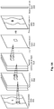
Images




Classifications
-
- G—PHYSICS
- G06—COMPUTING OR CALCULATING; COUNTING
- G06T—IMAGE DATA PROCESSING OR GENERATION, IN GENERAL
- G06T12/00—Tomographic reconstruction from projections
-
- G—PHYSICS
- G06—COMPUTING OR CALCULATING; COUNTING
- G06T—IMAGE DATA PROCESSING OR GENERATION, IN GENERAL
- G06T12/00—Tomographic reconstruction from projections
- G06T12/20—Inverse problem, i.e. transformations from projection space into object space
-
- G—PHYSICS
- G06—COMPUTING OR CALCULATING; COUNTING
- G06N—COMPUTING ARRANGEMENTS BASED ON SPECIFIC COMPUTATIONAL MODELS
- G06N3/00—Computing arrangements based on biological models
- G06N3/02—Neural networks
- G06N3/04—Architecture, e.g. interconnection topology
- G06N3/045—Combinations of networks
-
- G—PHYSICS
- G06—COMPUTING OR CALCULATING; COUNTING
- G06N—COMPUTING ARRANGEMENTS BASED ON SPECIFIC COMPUTATIONAL MODELS
- G06N3/00—Computing arrangements based on biological models
- G06N3/02—Neural networks
- G06N3/04—Architecture, e.g. interconnection topology
- G06N3/0464—Convolutional networks [CNN, ConvNet]
-
- G—PHYSICS
- G06—COMPUTING OR CALCULATING; COUNTING
- G06N—COMPUTING ARRANGEMENTS BASED ON SPECIFIC COMPUTATIONAL MODELS
- G06N3/00—Computing arrangements based on biological models
- G06N3/02—Neural networks
- G06N3/08—Learning methods
- G06N3/09—Supervised learning
-
- G—PHYSICS
- G06—COMPUTING OR CALCULATING; COUNTING
- G06T—IMAGE DATA PROCESSING OR GENERATION, IN GENERAL
- G06T3/00—Geometric image transformations in the plane of the image
- G06T3/40—Scaling of whole images or parts thereof, e.g. expanding or contracting
- G06T3/4046—Scaling of whole images or parts thereof, e.g. expanding or contracting using neural networks
-
- G—PHYSICS
- G06—COMPUTING OR CALCULATING; COUNTING
- G06T—IMAGE DATA PROCESSING OR GENERATION, IN GENERAL
- G06T5/00—Image enhancement or restoration
- G06T5/20—Image enhancement or restoration using local operators
-
- G—PHYSICS
- G06—COMPUTING OR CALCULATING; COUNTING
- G06T—IMAGE DATA PROCESSING OR GENERATION, IN GENERAL
- G06T5/00—Image enhancement or restoration
- G06T5/70—Denoising; Smoothing
-
- G—PHYSICS
- G06—COMPUTING OR CALCULATING; COUNTING
- G06T—IMAGE DATA PROCESSING OR GENERATION, IN GENERAL
- G06T2207/00—Indexing scheme for image analysis or image enhancement
- G06T2207/10—Image acquisition modality
- G06T2207/10072—Tomographic images
-
- G—PHYSICS
- G06—COMPUTING OR CALCULATING; COUNTING
- G06T—IMAGE DATA PROCESSING OR GENERATION, IN GENERAL
- G06T2207/00—Indexing scheme for image analysis or image enhancement
- G06T2207/20—Special algorithmic details
- G06T2207/20016—Hierarchical, coarse-to-fine, multiscale or multiresolution image processing; Pyramid transform
-
- G—PHYSICS
- G06—COMPUTING OR CALCULATING; COUNTING
- G06T—IMAGE DATA PROCESSING OR GENERATION, IN GENERAL
- G06T2207/00—Indexing scheme for image analysis or image enhancement
- G06T2207/20—Special algorithmic details
- G06T2207/20084—Artificial neural networks [ANN]
-
- G—PHYSICS
- G06—COMPUTING OR CALCULATING; COUNTING
- G06T—IMAGE DATA PROCESSING OR GENERATION, IN GENERAL
- G06T2207/00—Indexing scheme for image analysis or image enhancement
- G06T2207/20—Special algorithmic details
- G06T2207/20212—Image combination
- G06T2207/20221—Image fusion; Image merging
-
- G—PHYSICS
- G06—COMPUTING OR CALCULATING; COUNTING
- G06T—IMAGE DATA PROCESSING OR GENERATION, IN GENERAL
- G06T2211/00—Image generation
- G06T2211/40—Computed tomography
- G06T2211/421—Filtered back projection [FBP]
-
- G—PHYSICS
- G06—COMPUTING OR CALCULATING; COUNTING
- G06T—IMAGE DATA PROCESSING OR GENERATION, IN GENERAL
- G06T2211/00—Image generation
- G06T2211/40—Computed tomography
- G06T2211/436—Limited angle
Definitions
- the embodiments of the present disclosure relate to radiation imaging, and more particularly, to a method and device for reconstructing a CT image and a storage medium.
- X-ray CT imaging systems have been widely used in fields such as medical treatment, security inspection, industrial non-destructive detection, etc.
- Ray sources and detectors collect a series of projection data according to a certain trajectory, and a three-dimensional spatial distribution of linear attenuation coefficients of an object to be inspected may be obtained through recovery by using an image reconstruction algorithm.
- a CT image reconstruction process is to recover a linear attenuation coefficient distribution from data acquired by the detectors, which is a core step of CT imaging.
- analytical reconstruction algorithms such as filtered back-projection, Feldkmap-Davis-Kress (FDK), etc. and iterative reconstruction methods such as Algebra Reconstruction Technique (ART), Maximum A Posterior (MAP), etc. are mainly used in practical applications.
- a method and a device for reconstructing a CT image and a storage medium which can improve the quality of the reconstructed image.
- a method for reconstructing a Computed Tomography (CT) image comprising: performing CT scanning on an object to be inspected to obtain projection data on a first scale; generating projection data on a plurality of other scales from the projection data on the first scale; processing, on each scale, projection data on the corresponding scale by using a first convolutional neural network to obtain processed projection data, and performing a back-projection operation on the processed projection data to obtain a CT image on the corresponding scale; and fusing CT images on the plurality of scales to obtain a reconstructed image of the object to be inspected.
- CT Computed Tomography
- the CT scanning is one of the following: detector under-sampling scanning, sparse-angle scanning, intra-reconstruction scanning, finite angle scanning, and linear trajectory scanning, and the first convolutional neural network is a pooling layer-free convolutional neural network.
- the CT scanning is circular scanning or helical scanning
- the first convolutional neural network further comprises a plurality of pooling layers disposed after respective convolutional layers, and a fully connected layer.
- the method further comprises a step of: processing, on each scale, a CT image on the corresponding scale by using a second convolutional neural network.
- the method further comprises a step of: before generating the projection data on the plurality of other scales, filtering the projection data by using a ramp filter.
- the CT image on each scale is locally smoothed by using the second convolutional neural network.
- a convolutional kernel of a convolutional layer in the first convolutional neural network has a dimension of a detector pixel sequence and another dimension of a scanning angle, and a scale of the convolutional kernel of the convolutional layer in the first convolutional neural network on the dimension of the detector pixel sequence is set independently from a scale of the convolutional kernel of the convolutional layer in the first convolutional neural network on the dimension of the scanning angle.
- the first convolutional neural network comprises at least three convolutional layers, each of which has an activation function for performing a non-linear operation on projection data processed by the convolutional layer.
- the first convolutional neural network further comprises a back-projection layer for performing a back-projection operation on projection data processed by the convolutional layer.
- a length-width size parameter of a convolutional kernel of a convolutional layer in the first convolutional neural network which is closest to the back-projection layer is 1*1.
- the second convolutional neural network comprises an image domain initial convolutional layer and an end convolutional layer for processing the reconstructed image in an image domain.
- each convolutional layer included in the image domain initial convolutional layer has an activation function, and the end convolutional layer has no activation function.
- different convolutional kernels are convolved with the projection data on the first scale respectively to obtain the projection data on the plurality of other scales.
- pooling is performed on different scales on the projection data on the plurality of other scales to obtain projection data on the plurality of different scales.
- the step of fusing CT images on the plurality of scales comprises fusing the CT images on the plurality of scales progressively by an up-sampling operation, to finally obtain the reconstructed image of the object to be inspected.
- the step of fusing the CT images on the plurality of scales comprises fusing the CT images from the smallest scale to the largest scale progressively, wherein a process of fusion in each level comprises: in a case where a second scale is the smallest scale, performing an up-sampling operation on a CT image on the second scale to obtain a CT image on the first scale which is relatively larger, or in a case where the second scale is not the smallest scale, performing the up-sampling operation on a fused image on the second scale which is relatively smaller to obtain a CT image on the first scale which is relatively larger; and convolving an integral image formed of the reconstructed CT image on the first scale and the CT image obtained after the up-scaling operation with a particular convolutional kernel to obtain a fused image on the first scale.
- the method further comprises: outputting a fused image on the largest scale as a final CT image.
- the step of fusing CT images on the plurality of scales comprises: converting CT images on scales other than the largest scale into images on the largest scale by an up-sampling operation; and processing the CT image on the largest scale and the converted images on the largest scale as a whole by using a convolutional kernel to obtain a fused image.
- a device for reconstructing a Computed Tomography (CT) image comprising: a CT scanning apparatus configured to perform CT scanning on an object to be inspected to obtain projection data; a processor configured to: generate projection data on a plurality of other scales from the projection data on the first scale; process, on each scale, projection data on the corresponding scale by using a first convolutional neural network to obtain processed projection data, and perform a back-projection operation on the processed projection data to obtain a CT image on the corresponding scale; and fuse CT images on the plurality of scales to obtain a reconstructed image of the object to be inspected.
- CT Computed Tomography
- the CT scanning apparatus is configured to perform one of the following: detector under-sampling scanning, sparse-angle scanning, intra-reconstruction scanning, finite angle scanning, and linear trajectory scanning, and the first convolutional neural network is a pooling layer-free convolutional neural network.
- the CT scanning apparatus is configured to perform circular scanning or helical scanning
- the first convolutional neural network further comprises a plurality of pooling layers disposed after respective convolutional layers, and a fully connected layer.
- the processor is further configured to: process, on each scale, the reconstructed image by using a second convolutional neural network.
- the processor is further configured to: locally smooth the reconstructed image by using the second convolutional neural network.
- the processor is further configured to convolve the projection data on the first scale with different convolutional kernels to obtain projection data on other scales.
- the processor is further configured to: fuse the CT images on the plurality of scales progressively by an up-sampling operation, to finally obtain the reconstructed image of the object to be inspected.
- a computer-readable medium having computer programs stored thereon, which when being executed by a processor, cause the processor to perform the following steps: generating projection data on a plurality of other scales from projection data on a first scale; processing, on each scale, projection data on the corresponding scale by using a first convolutional neural network to obtain processed projection data, and performing a back-projection operation on the processed projection data to obtain a CT image on the corresponding scale; and fusing CT images on the plurality of scales to obtain a reconstructed image of the object to be inspected.
- the embodiments of the present disclosure propose a method and device for reconstructing a CT image and a storage medium.
- projection data (displayed as a sinogram, with a dimension being a detector pixel sequence, and another dimension being a scanning angle) on a plurality of scales is generated from projection data of an object to be inspected.
- projection data obtained through CT scanning is processed by using a convolutional neural network to obtain processed projection data (for example, a sinogram with enhanced characteristics in a projection domain).
- the processed projection data is back-projected on each scale to obtain CT images on various scales.
- the CT images on various scales are fused to obtain a reconstructed image of the object to be inspected.
- the quality of the reconstructed image can be improved, and particularly, a CT image with a higher quality can be reconstructed even in a case that projection data is incomplete due to detector under-sampling, sparse-angle scanning, intra-reconstruction, limited-angle scanning, or linear trajectory scanning, etc.
- the CT image may further be processed on each scale by using another convolutional neural network, and the above fusion process may then be performed to obtain a reconstructed image.
- Fig. 1 illustrates a schematic structural diagram of a device for reconstructing a CT image according to an embodiment of the present disclosure.
- the CT device according to the present embodiment comprises an X-ray source 10, a mechanical movement apparatus 50, a detector and data acquisition system 20, and a control and reconstruction apparatus 60, so as to perform CT scanning and reconstruction on an object 40 to be inspected.
- the X-ray source 10 is, for example, an X-ray machine, and an appropriate focus size of the X-ray machine is selected according to a resolution of imaging.
- an X-ray beam may be generated by using a linear accelerator.
- the mechanical movement apparatus 50 comprises a stage, a rack, a control system, etc.
- the stage may be translated to adjust a position of a center of rotation.
- the rack may be translated to align the X-ray source (the X-ray machine) 10, the detector, and the center of rotation.
- the description is made according to a circular scanning trajectory or a spiral trajectory of a rotational stage and a fixed rack.
- the method according to the present embodiment may also be implemented by a fixed stage and a rotational rack.
- the detector and data acquisition system 20 comprises an X-ray detector, a data acquisition circuit, etc.
- a solid detector, a gas detector, or other detectors may be used as the X-ray detector; however, the embodiments of the present disclosure are not limited thereto.
- the data acquisition circuit comprises a readout circuit, an acquisition trigger circuit, a data transmission circuit, etc.
- the control and reconstruction apparatus 60 comprises, for example, a computer device installed with a control program and a reconstruction program, and is responsible for performing control of an operation process of the CT system, including mechanical rotation, electrical control, safety interlock control, etc., and reconstructing a CT image from the projection data.
- Fig. 2 illustrates a schematic structural diagram of the control and reconstruction apparatus shown in Fig. 1 .
- data collected by the detector and data acquisition system 20 is stored in a storage device 61 through an interface unit 67 and a bus 68.
- a Read-Only Memory (ROM) 62 has configuration information and programs of a computer data processor stored therein.
- a Random Access Memory (RAM) 63 is configured to temporarily store various data during operation of a processor 65.
- computer programs for performing data processing such as a calculation program for reconstructing a CT image etc., are also stored in the storage device 61.
- the storage device 61, the read-only memory 62, the random access memory 63, an input apparatus 64, the processor 65, a display device 66, and the interface unit 67 are connected through the internal bus 68.
- instruction codes of the computer program instruct the processor 65 to execute an algorithm for reconstructing a CT image, and after obtaining a reconstruction result, display the reconstruction result on the display device 66 such as an LCD display, or output a processing result directly in a form of a hard copy such as printing.
- CT scanning is performed on an object to be inspected by using the above device to obtain projection data.
- projection data may be displayed in a form of a two-dimensional image.
- Fig. 3 illustrates an example of projection data obtained according to an embodiment of the present disclosure.
- a horizontal axis of the sinogram shown in Fig. 3 represents a detector pixel sequence (for example, from 1 to 256) and a vertical axis of the sinogram shown in Fig. 3 represents an angle (for example, from 1 degree to 360 degrees).
- the processor 65 in the control device then executes a reconstruction program to generate projection data (displayed as a sinogram, with a dimension being a detector pixel sequence, and another being a scanning angle) on a plurality of scales from the projection data of the object to be inspected. Then, projection data on each scale is processed by using a first convolutional neural network to obtain processed projection data, and a back-projection operation is performed on the processed projection data on each scale to obtain a CT image on the corresponding scale. Finally, CT images on various scales are fused to obtain a reconstructed image of the object to be inspected.
- the convolutional neural network may comprise convolutional layers, pooling layers, and fully connected layers.
- the convolutional layers each identify characteristics of an input data set, and each convolutional layer has a nonlinear activation function operation.
- the characteristics is refined by the pooling layers, and typical operations comprise mean-pooling and max-pooling.
- One or more fully connected layers implement a high-order signal nonlinear synthesis operation, and the full connected layer also has a nonlinear activation function.
- the commonly used nonlinear activation functions comprise Sigmoid, Tanh, ReLU. etc.
- Fig. 4 illustrates a schematic diagram of reconstructing an image using a convolutional neural network in the device according to an embodiment of the present disclosure.
- 360-degree circular CT scanning is performed on the object 40 to be inspected by using the inspection device shown in Fig. 1 , to obtain the projection data of the object 40 to be inspected and display the projection data as a sinogram 410.
- a plurality of convolutional kernels are used to be convolved with the sinogram 410 respectively, and pooling is performed on different scales on various convolved images (for example, 2, 3, 4, 6, etc.
- a pooling step may be selected as a pooling step), to obtain projection data on different scales, specifically, corresponding projection data on S scales which are projection data 410-1 on a first scale, projection data 410-2 on a second scale,..., projection data 410-S-1 on an (S-1) th scale, and projection data 410-S on an S th scale, as shown in Fig. 4 .
- the projection data on the S scales is convolved using corresponding Convolutional Neural Networks (CNNs), and a back-projection operation is performed to obtain reconstructed images on the corresponding scales.
- CNNs Convolutional Neural Networks
- a convolution operation is performed on the projection data 410-1 on the first scale using a CNN 420-1 on the first scale, and then back projection is performed to obtain a reconstructed image 430-1 on the first scale.
- a convolution operation is performed on the projection data 410-2 on the first scale using a CNN 420-2 on the second scale, and then back projection is performed to obtain a reconstructed image 430-2 on the second scale.
- a convolution operation is performed on the projection data 410-S-1 on the (S-1) th scale using a CNN 420-S-1 on the (S-1) th scale, and then back projection is performed to obtain a reconstructed image 430-S-1 on the (S-1) th scale.
- a convolution operation is performed on the projection data 410-S on the S th scale using a CNN 420-S on the S th scale, and then back projection is performed to obtain a reconstructed image 430-S on the S th scale.
- the reconstructed images 430-1, 430-2,..., 430-S-1 and 430-S are fused.
- the reconstructed image 430-S on the S th scale is up-sampled to obtain an up-sampled reconstructed image 440-S-1 on the (S-1) th scale.
- An integral image formed by the reconstructed image 440-S-1 on the (S-1) th scale and the up-sampled reconstructed image 440-S-1 is convolved on the (S-1) th scale with a convolutional kernel to obtain a fused reconstructed image on the (S-1) th scale.
- the above up-sampling is an inverse process of pooling.
- Up-sampling methods comprise, for example, bilinear interpolation, bicubic interpolation, edge information-based interpolation method, etc., and training is not required in the up-sampling process.
- the reconstructed image 430-S-1 and the up-sampled image 440-S-1 are both images having a scale of LxW, so that they form an LxWx2 image as a whole.
- a convolutional kernel having a scale of cxdx2 may be used to be convolved with the LxWx2 image to form a new LxWx1 image.
- the fused reconstructed image 450-S-1 on the (S-1) th scale is up-sampled to obtain an up-sampled reconstructed image 440-2 on the second scale.
- the up-sampled reconstructed image 440-2 on the second scale is obtained.
- An integral image formed by the reconstructed image 430-2 on the second scale and the up-sampled reconstructed image 440-2 is convolved on the second scale with a convolutional kernel to obtain a fused reconstructed image 450-2 on the second scale.
- the fused reconstructed image 450-2 on the second scale is up-sampled to obtain a reconstructed image 440-1 on the first scale.
- An integral image formed by the reconstructed image 430-1 on the first scale and the up-sampled reconstructed image 440-1 is convolved on the first scale with a convolutional kernel to obtain a fused reconstructed image on the first scale, i.e., an output image 440.
- an up-sampling operation is preferably used to progressively fuse CT images on a plurality of scales to finally obtain the reconstructed image of the object to be inspected.
- the present disclosure is not limited to progressive fusion, let alone progressive fusion from small to large. As long as the output image has the CT image on the maximum scale (maximum resolution) fused therein.
- CT images on the 2nd,..., (S-1)th and Sth scales may firstly be up-sampled to obtain images on the first scale, and an image formed by an CT image on the first scale with the maximum resolution and the remaining S-1 up-sampled images is convolved with a convolutional kernel in a thickness direction to obtain a fused image.
- Fig. 5A illustrates a structural diagram of a convolutional neural network used in the device according to an embodiment of the present disclosure.
- CNNs such as the CNN 420-1 on the first scale, the CNN 420-2 on the second scale, the CNN 420-S-1 on the (S-1) th scale, and the CNN 420-S on the S th scale.
- Fig. 4 may be formed by stacking different layers and may transform input data into output data.
- projection data for example, input projection data 511 shown in Fig. 5A
- processed projection data for example, processed projection data 515 shown in Fig. 5A ).
- the convolutional neural network shown in Fig. 5A comprises a plurality of convolutional layers, for example, a first convolutional layer 512, a second convolutional layer 513,..., an (n+1) th convolutional layer 514, where n is a natural number.
- These convolutional layers are essential blocks of the CNN. Parameters of each convolutional layer consist of a set of learnable convolutional kernels (or simply called convolutional kernels), each of which has a certain receptive field and extends over the entire depth of the input data.
- each convolutional kernel is convolved along a width and a height of the input data, a dot product of elements of the convolutional kernel and the input data is calculated, and a two-dimensional activation map of the convolutional kernel is generated.
- the network may learn a convolutional kernel which can be activated only when a specific type of characteristics is seen at a certain input spatial position.
- Activation maps of all the convolutional kernels are stacked in a depth direction to form all the output data of the convolutional layer. Therefore, each element in the output data may be interpreted as an output of a convolutional kernel which sees a small area in the input and shares parameters with other convolutional kernels in the same activation map.
- the output is a reconstructed image f.
- C (1) represents a convolutional kernel
- T represents "transpose.”
- a two-dimensional convolutional kernel on a certain scale has two dimensions, a first one of which is defined as a detector pixel sequence, and a second one of which is defined as a scanning angle here. Lengths of the convolutional kernel in the two dimensions do not need to be the same.
- a scale of the convolutional kernel C (1) on the dimension of the detector pixel sequence is set to be greater than a scale of the convolutional kernel C (1) on the dimension of the scanning angle, for example, 3*1, 5*1, and 5*3 convolutional kernels are used, as shown in Figs. 6A, 6B and 6C .
- a plurality of convolutional kernels may be set on each scale.
- a scale of a convolutional kernel of a convolutional layer in a convolutional neural network on the dimension of the detector pixel sequence is set independently from a scale of the convolutional kernel of the convolutional layer in the convolutional neural network on the dimension of the scanning angle.
- K (1) is defined as a thickness of this layer, i.e. a number of convolutional kernels. K (1) new sinograms are formed for this layer.
- a thickness of the first convolutional layer 512 is 3 (i.e., the first convolutional layer 420 has 3 convolutional kernels), wherein all the convolutional kernels are network parameters to be determined. These network parameters are obtained by training the convolutional neural network.
- the thickness of 3 in Fig. 5A is merely an example, and the present disclosure is not limited thereto.
- 24 convolutional kernels may be set for one convolutional layer, so that 24 sinograms are obtained for a first layer of the network.
- ReLU is selected as the activation function.
- a plurality of convolutional layers similar to the first convolutional layer may be set, with a thickness of each convolutional layer being K ( n ) .
- the second convolutional layer 513 is similar to the first convolutional layer 512, and a thickness of the second convolutional layer is K (2) .
- a sinogram output by a previous convolutional layer is further processed by using C (n) .
- the thickness of the second convolutional layer 513 is 3, wherein all the convolutional kernels are network parameters to be determined. These network parameters are obtained by training the convolutional neural network.
- the above-mentioned 3 is merely an example.
- 24 convolutional kernels may be set for one convolutional layer, so that 24 sinograms are obtained for the second convolutional layer (a second layer of the network).
- ReLu is selected as the activation function.
- a convolution operation is performed in a thickness direction in the second convolutional layer by using a convolutional kernel having a shape/size parameter of 18*1*1 to obtain an output of the second layer, with ReLu being the activation function.
- the (n+1) th convolutional layer 514 may be, for example, an ( n +1) th layer of the network, specifically an (n+1) th convolutional layer, and there may be or may not be another convolutional layer between the second convolutional layer 513 and the (n+1) th convolutional layer 514.
- a convolutional kernel of the (n+1) th convolutional layer has a shape/size parameter of K (n+1) ⁇ 1 ⁇ 1, a thickness of K (n+1) , and a length and a width each being 1.
- a sinogram output by a previous convolutional layer is further processed, to obtain the processed projection data (shown as a sinogram).
- This convolutional layer also has an activation function ⁇ ( g i ( n +1) ).
- the convolutional neural network as shown in Fig. 5A further comprises a back-projection layer 516.
- a projection matrix H may be determined based on the geometric relationship of the CT scanning device, and a back-projection operation may be performed on the processed sinogram to obtain a reconstructed CT image.
- the projection matrix is calculated by using an Siddon method, and elements of the system matrix correspond to connection weights of a back-projection connection layer.
- Fig. 5B illustrates a schematic structural diagram of another convolutional network used in the device according to an embodiment of the present disclosure.
- an input projection data 521, a convolutional layer 522, a convolutional layer 523, and a convolutional layer 524 are similar to the input projection data 511, the first convolutional layer 512, the second convolutional layer 513 and the (n+1) th convolutional layer 514 shown in Fig. 5A , and will not be repeated here.
- the structure shown in Fig. 5B differs from that shown in Fig. 5A in that in the structure shown in Fig.
- a second convolutional neural network is further provided, which comprises an image domain initial convolutional layer (one convolutional layer 527 is shown in Fig. 5B as an example, but the present disclosure is not limited thereto) and an end convolutional layer (a convolutional layer 528), and the reconstructed CT image is processed in the image domain, for example, is locally smoothed, to output the resultant image.
- an image domain initial convolutional layer one convolutional layer 527 is shown in Fig. 5B as an example, but the present disclosure is not limited thereto
- an end convolutional layer a convolutional layer 528
- Each of these convolutional layers in the image domain initial convolutional layer has an activation function ⁇ ( f ( k ) ).
- the output of the image domain initial convolutional layer is input to the convolutional layer 528.
- K (*-1) is a number of convolutional kernels of the previous convolutional layer. That is, convolution occurs in the thickness direction. This convolutional layer has no activation function.
- a pooling layer may be provided after one or more convolutional layers.
- a pooling layer is provided in a case that complete data is obtained by CT scanning (for example, full detector 360-degree circular scanning).
- CT scanning for example, full detector 360-degree circular scanning
- no pooling layer is provided in a case that incomplete data is obtained by CT scanning (for example, detector under-sampling, sparse-angle sampling, limited-angle, intra-reconstruction, or linear trajectory, etc.).
- the second convolutional neural network further comprises an output layer which is at the last layer of the network, and the output layer outputs the resultant image.
- the parameters of the first convolutional neural network and the second convolutional neural network are updated by making the cost function toward zero. In a case that the second convolutional neural network is not provided, the reconstructed image output by the first convolutional neural network is taken as the resultant image, and the parameters of the first convolutional neural network are updated based on the above cost function.
- ramp convolution may further be performed on a sinogram (for example, the sinogram 410 shown in Fig. 4 ) obtained by performing CT scanning by using an RL ramp filter.
- a sinogram for example, the sinogram 410 shown in Fig. 4
- other activation functions may also be used.
- the ReLU function is more commonly used as it allows a neural network to be trained several times faster without having a significant impact on the accuracy.
- network parameters are trained. For example, a basic mathematical model of a scanned object is established and CT simulation data is generated by modeling an actual system.
- CT simulation data of a plurality of scanned objects may further be used as an input of the network, and an image true value of the scanned objects is used as a marker, to train the network parameters.
- the object is also scanned on the actual system, to obtain CT scanning data, which is input to the network for reconstruction and testing.
- Targeted image processing is performed on a test result, for example, known local smooth regions are locally smoothed.
- the network is further trained by using the processed image as a marker to achieve fine tuning of the network parameters.
- Fig. 7 is a schematic flowchart illustrating a method according to an embodiment of the present disclosure.
- CT scanning is performed on the object to be inspected to obtain projection data on the first scale.
- the CT scanning here may be mono-energy scanning or multi-energy scanning, and the embodiments of the present disclosure are not limited thereto.
- step S720 the projection data on the first scale is filtered by using a ramp filter.
- the projection data is filtered by using an RL ramp filter. It can be understood by those skilled in the art that other filters may be used here or filtering is not performed.
- step S730 projection data on a plurality of other scales is generated from the projection data on the first scale.
- original projection data shown as the sinogram 410
- convolutional kernels on different scales to obtain projection data on different scales.
- step S740 projection data on each scale is processed on the corresponding scale by using a first convolutional neural network to obtain processed projection data, and a back-projection operation is performed on the processed projection data to obtain a CT image on the corresponding scale.
- the projection data on each scale is processed in a projection domain by using a convolutional neural network (for example, 512, 513, or 514), to obtain processed projection data on each scale.
- the projection data is processed by using a convolutional neural network obtained by training to obtain a processed sinogram, as shown in Fig. 5A .
- a back-projection operation is performed on the processed projection data on each scale.
- a back-projection operation is performed in the back-projection layer 516 shown in Fig. 5A to obtain a CT image on a corresponding scale.
- post-processing may be performed on the CT image after the CT image is obtained, for example, the reconstructed CT image is processed by using the second convolutional neural network 527/528 to obtain the resultant image on this scale.
- the reconstructed image is locally smoothed or other image processing operations such as segmentation, edge enhancement, and equalization, etc. may be performed on the reconstructed image.
- step S750 CT images on a plurality of scales are fused through up-sampling and convolution in the thickness direction to obtain a reconstructed image of the object to be inspected.
- Fig. 8 is a schematic diagram of a scanning apparatus which implements limited-angle CT scanning according to another embodiment of the present disclosure.
- the X rays are received by the detector 30, converted into electrical signals, further converted into digital signals indicating attenuation values, and reconstructed in a computer as projection data.
- limited-angle for example, 130-degree
- Fig. 9 is a schematic diagram of a scanning apparatus which implements a sparse-angle sampling scanning method according to yet another embodiment of the present disclosure.
- the X rays are received by the detector 30, converted into electrical signals, further converted into digital signals indicating attenuation values, and reconstructed in a compute as projection data r.
- an image with a higher quality can be reconstructed even if CT scanning at a number of rotation positions (for example, six positions) is performed on the object 40 to be inspected. In this way, an image with a higher quality can be reconstructed from the incomplete projection data even if spare-angle CT scanning is performed on the object to be inspected.
- Fig. 10 is a schematic diagram of a scanning apparatus which implements an intra-reconstruction scanning method according to yet another embodiment of the present disclosure.
- the X rays are received by the detector 30, converted into electrical signals, further converted into digital signals indicating attenuation values, and reconstructed in a computer as projection data.
- Fig. 11 is a schematic diagram of a scanning apparatus which implements a detector under-sampling scanning method according to yet another embodiment of the present disclosure.
- the X rays are received by the detector 30, converted into electrical signals, further converted into digital signals indicating attenuation values, and reconstructed in a computer as projection data.
- the detector 30 is set to be in an under-sampled form, for example, under-sampling is realized by spacing various detector units apart by a predetermined distance. In this way, with the solutions described above, an image with a higher quality can be reconstructed even if detector under-sampling CT scanning is performed on the object 40 to be inspected.
- Fig. 12 is a schematic diagram illustrating incomplete projection data involved in the scanning modes shown in Figs. 8, 9 , 10, and 11 .
- the projection data obtained by sparse-angle sampling CT scanning, limited-angle CT scanning, detector under-sampling CT scanning, and intra-reconstruction CT scanning are all incomplete.
- the projection data is incomplete, with the above solutions, an image with a higher quality can be reconstructed from the incomplete projection data.
- Fig. 13 illustrates a schematic diagram of a scanning apparatus which implements linear trajectory CT scanning according to yet another embodiment of the present disclosure.
- the X rays are received by the detector 30, converted into electrical signals, further converted into digital signals indicating attenuation values, and reconstructed in a computer as projection data.
- the object 40 to be inspected moves along a linear trajectory on a conveyor belt parallel to the detectors.
- a field angle of the ray source formed by the detectors in a horizontal direction is as large as possible, and the detectors cover the object in a vertical direction.
- the detector array is placed on an opposite side of the source, and a horizontal field angle ⁇ of the rays is required to be more than 90 degrees, to obtain protection data through the linear trajectory CT scanning.
- the embodiments of the present disclosure provide an X-ray CT reconstruction method based on a convolutional neural network to deeply mine data information, form a convolutional neural network and system-specific parameters, and obtain an efficient CT image reconstruction method.
- the method according to the present disclosure can be flexibly applied to different CT scanning modes and system architectures and can be used in the fields of medical diagnosis, industrial non-destructive detection and security inspection.
- Examples of a signal bearing medium include, but are not limited to, the following: a recordable type medium such as a floppy disk, a hard disk drive, a Compact Disc (CD), a Digital Versatile Disk (DVD), a digital tape, a computer memory, etc.; and a transmission type medium such as a digital and/or an analog communication medium (e.g., a fiber optic cable, a waveguide, a wired communications link, a wireless communication link, etc.).
Landscapes
- Engineering & Computer Science (AREA)
- Theoretical Computer Science (AREA)
- Physics & Mathematics (AREA)
- General Physics & Mathematics (AREA)
- Evolutionary Computation (AREA)
- Artificial Intelligence (AREA)
- Mathematical Physics (AREA)
- General Health & Medical Sciences (AREA)
- Health & Medical Sciences (AREA)
- Computational Linguistics (AREA)
- Data Mining & Analysis (AREA)
- Biomedical Technology (AREA)
- Life Sciences & Earth Sciences (AREA)
- Molecular Biology (AREA)
- Computing Systems (AREA)
- General Engineering & Computer Science (AREA)
- Biophysics (AREA)
- Software Systems (AREA)
- Apparatus For Radiation Diagnosis (AREA)
- Image Processing (AREA)
- Analysing Materials By The Use Of Radiation (AREA)
- Algebra (AREA)
- Mathematical Analysis (AREA)
- Mathematical Optimization (AREA)
- Pure & Applied Mathematics (AREA)
- Image Analysis (AREA)
Abstract
Description
- This application claims priority to the Chinese Patent Application No.
201710615147.5, filed on July 25, 2017 - The embodiments of the present disclosure relate to radiation imaging, and more particularly, to a method and device for reconstructing a CT image and a storage medium.
- X-ray CT imaging systems have been widely used in fields such as medical treatment, security inspection, industrial non-destructive detection, etc. Ray sources and detectors collect a series of projection data according to a certain trajectory, and a three-dimensional spatial distribution of linear attenuation coefficients of an object to be inspected may be obtained through recovery by using an image reconstruction algorithm. A CT image reconstruction process is to recover a linear attenuation coefficient distribution from data acquired by the detectors, which is a core step of CT imaging. Currently, analytical reconstruction algorithms such as filtered back-projection, Feldkmap-Davis-Kress (FDK), etc. and iterative reconstruction methods such as Algebra Reconstruction Technique (ART), Maximum A Posterior (MAP), etc. are mainly used in practical applications.
- With the increasing diversity of demands for X-ray CT imaging, the requirements for reducing a radiation dosage have become higher and higher, and the image quality which can be achieved by the reconstruction methods in the related art has approached the limit. There is a need to develop a new CT image reconstruction technique.
- In order to address one or more problems in the related art, there are provided a method and a device for reconstructing a CT image and a storage medium, which can improve the quality of the reconstructed image.
- According to an aspect of the present disclosure, there is provided a method for reconstructing a Computed Tomography (CT) image, comprising: performing CT scanning on an object to be inspected to obtain projection data on a first scale; generating projection data on a plurality of other scales from the projection data on the first scale; processing, on each scale, projection data on the corresponding scale by using a first convolutional neural network to obtain processed projection data, and performing a back-projection operation on the processed projection data to obtain a CT image on the corresponding scale; and fusing CT images on the plurality of scales to obtain a reconstructed image of the object to be inspected.
- According to an embodiment of the present disclosure, the CT scanning is one of the following: detector under-sampling scanning, sparse-angle scanning, intra-reconstruction scanning, finite angle scanning, and linear trajectory scanning, and the first convolutional neural network is a pooling layer-free convolutional neural network.
- According to an embodiment of the present disclosure, the CT scanning is circular scanning or helical scanning, and the first convolutional neural network further comprises a plurality of pooling layers disposed after respective convolutional layers, and a fully connected layer.
- According to an embodiment of the present disclosure, the method further comprises a step of: processing, on each scale, a CT image on the corresponding scale by using a second convolutional neural network.
- According to an embodiment of the present disclosure, the method further comprises a step of: before generating the projection data on the plurality of other scales, filtering the projection data by using a ramp filter.
- According to an embodiment of the present disclosure, the CT image on each scale is locally smoothed by using the second convolutional neural network.
- According to an embodiment of the present disclosure, a convolutional kernel of a convolutional layer in the first convolutional neural network has a dimension of a detector pixel sequence and another dimension of a scanning angle, and a scale of the convolutional kernel of the convolutional layer in the first convolutional neural network on the dimension of the detector pixel sequence is set independently from a scale of the convolutional kernel of the convolutional layer in the first convolutional neural network on the dimension of the scanning angle.
- According to an embodiment of the present disclosure, the first convolutional neural network comprises at least three convolutional layers, each of which has an activation function for performing a non-linear operation on projection data processed by the convolutional layer.
- According to an embodiment of the present disclosure, the first convolutional neural network further comprises a back-projection layer for performing a back-projection operation on projection data processed by the convolutional layer.
- According to an embodiment of the present disclosure, a length-width size parameter of a convolutional kernel of a convolutional layer in the first convolutional neural network which is closest to the back-projection layer is 1*1.
- According to an embodiment of the present disclosure, the second convolutional neural network comprises an image domain initial convolutional layer and an end convolutional layer for processing the reconstructed image in an image domain.
- According to an embodiment of the present disclosure, each convolutional layer included in the image domain initial convolutional layer has an activation function, and the end convolutional layer has no activation function.
- According to an embodiment of the present disclosure, different convolutional kernels are convolved with the projection data on the first scale respectively to obtain the projection data on the plurality of other scales.
- According to an embodiment of the present disclosure, pooling is performed on different scales on the projection data on the plurality of other scales to obtain projection data on the plurality of different scales.
- According to an embodiment of the present disclosure, the step of fusing CT images on the plurality of scales comprises fusing the CT images on the plurality of scales progressively by an up-sampling operation, to finally obtain the reconstructed image of the object to be inspected.
- According to an embodiment of the present disclosure, the step of fusing the CT images on the plurality of scales comprises fusing the CT images from the smallest scale to the largest scale progressively, wherein a process of fusion in each level comprises: in a case where a second scale is the smallest scale, performing an up-sampling operation on a CT image on the second scale to obtain a CT image on the first scale which is relatively larger, or in a case where the second scale is not the smallest scale, performing the up-sampling operation on a fused image on the second scale which is relatively smaller to obtain a CT image on the first scale which is relatively larger; and convolving an integral image formed of the reconstructed CT image on the first scale and the CT image obtained after the up-scaling operation with a particular convolutional kernel to obtain a fused image on the first scale.
- According to an embodiment of the present disclosure, the method further comprises: outputting a fused image on the largest scale as a final CT image.
- According to an embodiment of the present disclosure, the step of fusing CT images on the plurality of scales comprises: converting CT images on scales other than the largest scale into images on the largest scale by an up-sampling operation; and processing the CT image on the largest scale and the converted images on the largest scale as a whole by using a convolutional kernel to obtain a fused image.
- According to another aspect of the present disclosure, there is provided a device for reconstructing a Computed Tomography (CT) image, comprising: a CT scanning apparatus configured to perform CT scanning on an object to be inspected to obtain projection data; a processor configured to: generate projection data on a plurality of other scales from the projection data on the first scale; process, on each scale, projection data on the corresponding scale by using a first convolutional neural network to obtain processed projection data, and perform a back-projection operation on the processed projection data to obtain a CT image on the corresponding scale; and fuse CT images on the plurality of scales to obtain a reconstructed image of the object to be inspected.
- According to an embodiment of the present disclosure, the CT scanning apparatus is configured to perform one of the following: detector under-sampling scanning, sparse-angle scanning, intra-reconstruction scanning, finite angle scanning, and linear trajectory scanning, and the first convolutional neural network is a pooling layer-free convolutional neural network.
- According to an embodiment of the present disclosure, the CT scanning apparatus is configured to perform circular scanning or helical scanning, and the first convolutional neural network further comprises a plurality of pooling layers disposed after respective convolutional layers, and a fully connected layer.
- According to an embodiment of the present disclosure, the processor is further configured to: process, on each scale, the reconstructed image by using a second convolutional neural network.
- According to an embodiment of the present disclosure, the processor is further configured to: locally smooth the reconstructed image by using the second convolutional neural network.
- According to an embodiment of the present disclosure, the processor is further configured to convolve the projection data on the first scale with different convolutional kernels to obtain projection data on other scales.
- According to an embodiment of the present disclosure, the processor is further configured to: fuse the CT images on the plurality of scales progressively by an up-sampling operation, to finally obtain the reconstructed image of the object to be inspected.
- According to yet another aspect of the present disclosure, there is provided a computer-readable medium having computer programs stored thereon, which when being executed by a processor, cause the processor to perform the following steps: generating projection data on a plurality of other scales from projection data on a first scale; processing, on each scale, projection data on the corresponding scale by using a first convolutional neural network to obtain processed projection data, and performing a back-projection operation on the processed projection data to obtain a CT image on the corresponding scale; and fusing CT images on the plurality of scales to obtain a reconstructed image of the object to be inspected.
- With the solutions according to the embodiments of the present disclosure described above, a CT image with a higher quality can be reconstructed.
- For better understanding of the present disclosure, the present disclosure will be described in detail with reference to the following accompanying drawings:
-
Fig. 1 illustrates a schematic structural diagram of a device for reconstructing a CT image according to an embodiment of the present disclosure; -
Fig. 2 is a schematic structural diagram of a control and reconstruction apparatus in the device shown inFig. 1 ; -
Fig. 3 illustrates an example of a sinogram of projection data obtained by the device according to an embodiment of the present disclosure; -
Fig. 4 illustrates a schematic diagram of reconstructing an image using a convolutional neural network in the device according to an embodiment of the present disclosure; -
Fig. 5A illustrates a schematic structural diagram of a convolutional neural network used in the device according to an embodiment of the present disclosure; -
Fig. 5B illustrates a schematic structural diagram of another convolutional network used in the device according to an embodiment of the present disclosure; -
Figs. 6A , 6B, and 6C illustrate a diagram of sizes of filter cores used in the device according to an embodiment of the present disclosure; -
Fig. 7 is a schematic flowchart illustrating a method according to an embodiment of the present disclosure; -
Fig. 8 is a schematic diagram of a scanning apparatus which implements limited-angle CT scanning according to another embodiment of the present disclosure; -
Fig. 9 is a schematic diagram of a scanning apparatus which implements a sparse-angle sampling scanning method according to yet another embodiment of the present disclosure; -
Fig. 10 is a schematic diagram of a scanning apparatus which implements an intra-reconstruction scanning method according to yet another embodiment of the present disclosure; -
Fig. 11 is a schematic diagram of a scanning apparatus which implements a detector under-sampling scanning method according to yet another embodiment of the present disclosure; -
Fig. 12 illustrates a schematic diagram of data contained in sinograms in the different scanning modes shown inFigs. 8, 9 ,10, and 11 ; and -
Fig. 13 illustrates a schematic diagram of a scanning apparatus which implements linear trajectory CT scanning according to yet another embodiment of the present disclosure. - The specific embodiments of the present disclosure will be described in detail below. It should be noted that the embodiments herein are used for illustration only, without limiting the present disclosure. In the description below, a number of specific details are explained to provide better understanding of the present disclosure. However, it is apparent to those skilled in the art that the present disclosure can be implemented without these specific details. In other instances, well known circuits, materials or methods are not described specifically so as not to obscure the present disclosure.
- Throughout the specification, the reference to "one embodiment," "an embodiment," "one example" or "an example" means that the specific features, structures or properties described in conjunction with the embodiment or example are included in at least one embodiment of the present disclosure. Therefore, the phrases "in one embodiment," "in an embodiment," "in one example" or "in an example" occurred in various positions throughout the specification may not necessarily refer to the same embodiment or example. Furthermore, specific features, structures or properties may be combined into one or more embodiments or examples in any appropriate combination and/or sub-combination. Moreover, it should be understood by those skilled in the art that the term "and/or" used herein means any and all combinations of one or more listed items.
- For one or more problems in the related art, the embodiments of the present disclosure propose a method and device for reconstructing a CT image and a storage medium. According to the embodiments of the present disclosure, projection data (displayed as a sinogram, with a dimension being a detector pixel sequence, and another dimension being a scanning angle) on a plurality of scales is generated from projection data of an object to be inspected. Then, for projection data on each scale, projection data obtained through CT scanning is processed by using a convolutional neural network to obtain processed projection data (for example, a sinogram with enhanced characteristics in a projection domain). Then, the processed projection data is back-projected on each scale to obtain CT images on various scales. The CT images on various scales are fused to obtain a reconstructed image of the object to be inspected. In this way, the quality of the reconstructed image can be improved, and particularly, a CT image with a higher quality can be reconstructed even in a case that projection data is incomplete due to detector under-sampling, sparse-angle scanning, intra-reconstruction, limited-angle scanning, or linear trajectory scanning, etc. In other embodiments, the CT image may further be processed on each scale by using another convolutional neural network, and the above fusion process may then be performed to obtain a reconstructed image.
-
Fig. 1 illustrates a schematic structural diagram of a device for reconstructing a CT image according to an embodiment of the present disclosure. As shown inFig. 1 , the CT device according to the present embodiment comprises anX-ray source 10, amechanical movement apparatus 50, a detector anddata acquisition system 20, and a control andreconstruction apparatus 60, so as to perform CT scanning and reconstruction on anobject 40 to be inspected. - The
X-ray source 10 is, for example, an X-ray machine, and an appropriate focus size of the X-ray machine is selected according to a resolution of imaging. In other embodiments, instead of using the X-ray machine, an X-ray beam may be generated by using a linear accelerator. - The
mechanical movement apparatus 50 comprises a stage, a rack, a control system, etc. The stage may be translated to adjust a position of a center of rotation. The rack may be translated to align the X-ray source (the X-ray machine) 10, the detector, and the center of rotation. In the present embodiment, the description is made according to a circular scanning trajectory or a spiral trajectory of a rotational stage and a fixed rack. As the movement of the stage with respect to the rack is a relative motion, the method according to the present embodiment may also be implemented by a fixed stage and a rotational rack. - The detector and
data acquisition system 20 comprises an X-ray detector, a data acquisition circuit, etc. A solid detector, a gas detector, or other detectors may be used as the X-ray detector; however, the embodiments of the present disclosure are not limited thereto. The data acquisition circuit comprises a readout circuit, an acquisition trigger circuit, a data transmission circuit, etc. - The control and
reconstruction apparatus 60 comprises, for example, a computer device installed with a control program and a reconstruction program, and is responsible for performing control of an operation process of the CT system, including mechanical rotation, electrical control, safety interlock control, etc., and reconstructing a CT image from the projection data. -
Fig. 2 illustrates a schematic structural diagram of the control and reconstruction apparatus shown inFig. 1 . As shown inFig. 2 , data collected by the detector anddata acquisition system 20 is stored in astorage device 61 through aninterface unit 67 and abus 68. A Read-Only Memory (ROM) 62 has configuration information and programs of a computer data processor stored therein. A Random Access Memory (RAM) 63 is configured to temporarily store various data during operation of aprocessor 65. In addition, computer programs for performing data processing, such as a calculation program for reconstructing a CT image etc., are also stored in thestorage device 61. Thestorage device 61, the read-only memory 62, therandom access memory 63, aninput apparatus 64, theprocessor 65, adisplay device 66, and theinterface unit 67 are connected through theinternal bus 68. - After a user inputs an operation command through the
input apparatus 64 such as a keyboard, a mouse, etc., instruction codes of the computer program instruct theprocessor 65 to execute an algorithm for reconstructing a CT image, and after obtaining a reconstruction result, display the reconstruction result on thedisplay device 66 such as an LCD display, or output a processing result directly in a form of a hard copy such as printing. - According to an embodiment of the present disclosure, CT scanning is performed on an object to be inspected by using the above device to obtain projection data. Generally, such projection data may be displayed in a form of a two-dimensional image.
Fig. 3 illustrates an example of projection data obtained according to an embodiment of the present disclosure. A horizontal axis of the sinogram shown inFig. 3 represents a detector pixel sequence (for example, from 1 to 256) and a vertical axis of the sinogram shown inFig. 3 represents an angle (for example, from 1 degree to 360 degrees). Theprocessor 65 in the control device then executes a reconstruction program to generate projection data (displayed as a sinogram, with a dimension being a detector pixel sequence, and another being a scanning angle) on a plurality of scales from the projection data of the object to be inspected. Then, projection data on each scale is processed by using a first convolutional neural network to obtain processed projection data, and a back-projection operation is performed on the processed projection data on each scale to obtain a CT image on the corresponding scale. Finally, CT images on various scales are fused to obtain a reconstructed image of the object to be inspected. - As described above, in the embodiments of the present disclosure, after the scale of the projection data is transformed, projection data on each scale is processed by using a convolutional neural network in a projection domain, then a back-projection operation is performed to reconstruct a CT image on the corresponding scale, and CT images on various scales are fused. The convolutional neural network may comprise convolutional layers, pooling layers, and fully connected layers. The convolutional layers each identify characteristics of an input data set, and each convolutional layer has a nonlinear activation function operation. The characteristics is refined by the pooling layers, and typical operations comprise mean-pooling and max-pooling. One or more fully connected layers implement a high-order signal nonlinear synthesis operation, and the full connected layer also has a nonlinear activation function. The commonly used nonlinear activation functions comprise Sigmoid, Tanh, ReLU. etc.
-
Fig. 4 illustrates a schematic diagram of reconstructing an image using a convolutional neural network in the device according to an embodiment of the present disclosure. - Specifically, 360-degree circular CT scanning is performed on the
object 40 to be inspected by using the inspection device shown inFig. 1 , to obtain the projection data of theobject 40 to be inspected and display the projection data as asinogram 410. Then, a plurality of convolutional kernels are used to be convolved with thesinogram 410 respectively, and pooling is performed on different scales on various convolved images (for example, 2, 3, 4, 6, etc. may be selected as a pooling step), to obtain projection data on different scales, specifically, corresponding projection data on S scales which are projection data 410-1 on a first scale, projection data 410-2 on a second scale,..., projection data 410-S-1 on an (S-1)th scale, and projection data 410-S on an Sth scale, as shown inFig. 4 . Then, the projection data on the S scales is convolved using corresponding Convolutional Neural Networks (CNNs), and a back-projection operation is performed to obtain reconstructed images on the corresponding scales. - As shown in
Fig. 4 , for the projection data 410-1 on the first scale, a convolution operation is performed on the projection data 410-1 on the first scale using a CNN 420-1 on the first scale, and then back projection is performed to obtain a reconstructed image 430-1 on the first scale. Similarly, for the projection data 410-2 on the second scale, a convolution operation is performed on the projection data 410-2 on the first scale using a CNN 420-2 on the second scale, and then back projection is performed to obtain a reconstructed image 430-2 on the second scale. For the projection data 410-S-1 on the (S-1)th scale, a convolution operation is performed on the projection data 410-S-1 on the (S-1)th scale using a CNN 420-S-1 on the (S-1)th scale, and then back projection is performed to obtain a reconstructed image 430-S-1 on the (S-1)th scale. For the projection data 410-S on the Sth scale, a convolution operation is performed on the projection data 410-S on the Sth scale using a CNN 420-S on the Sth scale, and then back projection is performed to obtain a reconstructed image 430-S on the Sth scale. - Then, the reconstructed images 430-1, 430-2,..., 430-S-1 and 430-S are fused. Specifically, as shown in
Fig. 4 , the reconstructed image 430-S on the Sth scale is up-sampled to obtain an up-sampled reconstructed image 440-S-1 on the (S-1)th scale. An integral image formed by the reconstructed image 440-S-1 on the (S-1)th scale and the up-sampled reconstructed image 440-S-1 is convolved on the (S-1)th scale with a convolutional kernel to obtain a fused reconstructed image on the (S-1)th scale. The above up-sampling is an inverse process of pooling. Up-sampling methods comprise, for example, bilinear interpolation, bicubic interpolation, edge information-based interpolation method, etc., and training is not required in the up-sampling process. For example, the reconstructed image 430-S-1 and the up-sampled image 440-S-1 are both images having a scale of LxW, so that they form an LxWx2 image as a whole. In this case, a convolutional kernel having a scale of cxdx2 may be used to be convolved with the LxWx2 image to form a new LxWx1 image. - Next, the fused reconstructed image 450-S-1 on the (S-1)th scale is up-sampled to obtain an up-sampled reconstructed image 440-2 on the second scale. Similarly, the up-sampled reconstructed image 440-2 on the second scale is obtained. An integral image formed by the reconstructed image 430-2 on the second scale and the up-sampled reconstructed image 440-2 is convolved on the second scale with a convolutional kernel to obtain a fused reconstructed image 450-2 on the second scale.
- Furthermore, the fused reconstructed image 450-2 on the second scale is up-sampled to obtain a reconstructed image 440-1 on the first scale. An integral image formed by the reconstructed image 430-1 on the first scale and the up-sampled reconstructed image 440-1 is convolved on the first scale with a convolutional kernel to obtain a fused reconstructed image on the first scale, i.e., an
output image 440. - In the present disclosure, an up-sampling operation is preferably used to progressively fuse CT images on a plurality of scales to finally obtain the reconstructed image of the object to be inspected. However, the present disclosure is not limited to progressive fusion, let alone progressive fusion from small to large. As long as the output image has the CT image on the maximum scale (maximum resolution) fused therein. For example, by taking scales being 1, 2,..., S-1 and S from large to small as an examples, CT images on the 2nd,..., (S-1)th and Sth scales may firstly be up-sampled to obtain images on the first scale, and an image formed by an CT image on the first scale with the maximum resolution and the remaining S-1 up-sampled images is convolved with a convolutional kernel in a thickness direction to obtain a fused image.
-
Fig. 5A illustrates a structural diagram of a convolutional neural network used in the device according to an embodiment of the present disclosure. As shown inFig. 5A , for example, CNNs such as the CNN 420-1 on the first scale, the CNN 420-2 on the second scale, the CNN 420-S-1 on the (S-1)th scale, and the CNN 420-S on the Sth scale. shown inFig. 4 may be formed by stacking different layers and may transform input data into output data. For example, projection data (for example,input projection data 511 shown inFig. 5A ) obtained by CT scanning is processed to obtain processed projection data (for example, processedprojection data 515 shown inFig. 5A ). - The convolutional neural network shown in
Fig. 5A comprises a plurality of convolutional layers, for example, a firstconvolutional layer 512, a secondconvolutional layer 513,..., an (n+1)thconvolutional layer 514, where n is a natural number. These convolutional layers are essential blocks of the CNN. Parameters of each convolutional layer consist of a set of learnable convolutional kernels (or simply called convolutional kernels), each of which has a certain receptive field and extends over the entire depth of the input data. In a forward process, each convolutional kernel is convolved along a width and a height of the input data, a dot product of elements of the convolutional kernel and the input data is calculated, and a two-dimensional activation map of the convolutional kernel is generated. As a result, the network may learn a convolutional kernel which can be activated only when a specific type of characteristics is seen at a certain input spatial position. - Activation maps of all the convolutional kernels are stacked in a depth direction to form all the output data of the convolutional layer. Therefore, each element in the output data may be interpreted as an output of a convolutional kernel which sees a small area in the input and shares parameters with other convolutional kernels in the same activation map.
- For example, the input projection data obtained by CT scanning is g = {g 1,g 2,···,gM }, and the data in the projection domain after a plurality of preliminary convolution operations and pooling operations have been performed are g i , i=1, 2, ......, S-1, and S respectively. The line integral projection process is H = {Hmn }
M×N , and the output is a reconstructed image f. - The first
convolutional layer 512 implements the following operation:
Figs. 6A, 6B and 6C . A plurality of convolutional kernels may be set on each scale. A scale of a convolutional kernel of a convolutional layer in a convolutional neural network on the dimension of the detector pixel sequence is set independently from a scale of the convolutional kernel of the convolutional layer in the convolutional neural network on the dimension of the scanning angle. The convolutional layer has an activation function ϕ(g i (1)), where i=1, 2, ......, S-1, S. K (1) is defined as a thickness of this layer, i.e. a number of convolutional kernels. K (1) new sinograms are formed for this layer. InFig. 4 , a thickness of the firstconvolutional layer 512 is 3 (i.e., the firstconvolutional layer 420 has 3 convolutional kernels), wherein all the convolutional kernels are network parameters to be determined. These network parameters are obtained by training the convolutional neural network. The thickness of 3 inFig. 5A is merely an example, and the present disclosure is not limited thereto. By taking the reconstruction of two-dimensional parallel beam CT scanning as an example, 24 convolutional kernels may be set for one convolutional layer, so that 24 sinograms are obtained for a first layer of the network. ReLU is selected as the activation function. ReLU is an abbreviation for a Rectified Linear Unit. This is a neuron layer in which a non-saturated activation function f(x) = max(0,x) is applied. A decision function and non-linear characteristics of the entire network are added without affecting the receptive field of the convolutional layer. - A plurality of convolutional layers similar to the first convolutional layer may be set, with a thickness of each convolutional layer being K (n).
- The second
convolutional layer 513 is similar to the firstconvolutional layer 512, and a thickness of the second convolutional layer is K (2). For example, a sinogram output by a previous convolutional layer is further processed by using C(n). As shown inFig. 4 , the thickness of the secondconvolutional layer 513 is 3, wherein all the convolutional kernels are network parameters to be determined. These network parameters are obtained by training the convolutional neural network. The above-mentioned 3 is merely an example. Similarly, 24 convolutional kernels may be set for one convolutional layer, so that 24 sinograms are obtained for the second convolutional layer (a second layer of the network). Here, ReLu is selected as the activation function. In another embodiment, a convolution operation is performed in a thickness direction in the second convolutional layer by using a convolutional kernel having a shape/size parameter of 18*1*1 to obtain an output of the second layer, with ReLu being the activation function. - The (n+1)th
convolutional layer 514 may be, for example, an (n+1)th layer of the network, specifically an (n+1)th convolutional layer, and there may be or may not be another convolutional layer between the secondconvolutional layer 513 and the (n+1)thconvolutional layer 514. The (n+1)thconvolutional layer 514 implements the following operation:

- The convolutional neural network as shown in
Fig. 5A further comprises a back-projection layer 516. The back-projection layer 516 is, for example, an (n+2)th layer of the convolutional neural network and implements the following operation:
-
Fig. 5B illustrates a schematic structural diagram of another convolutional network used in the device according to an embodiment of the present disclosure. As shown inFig. 5B , aninput projection data 521, aconvolutional layer 522, aconvolutional layer 523, and aconvolutional layer 524 are similar to theinput projection data 511, the firstconvolutional layer 512, the secondconvolutional layer 513 and the (n+1)thconvolutional layer 514 shown inFig. 5A , and will not be repeated here. The structure shown inFig. 5B differs from that shown inFig. 5A in that in the structure shown inFig. 5B , a second convolutional neural network is further provided, which comprises an image domain initial convolutional layer (oneconvolutional layer 527 is shown inFig. 5B as an example, but the present disclosure is not limited thereto) and an end convolutional layer (a convolutional layer 528), and the reconstructed CT image is processed in the image domain, for example, is locally smoothed, to output the resultant image. - For example, if the image domain initial convolutional layer comprises only one
convolutional layer 527, theconvolutional layer 527 described above may be represented as f (n') = (C (n')) T f (n+2). If the image domain initial convolutional layer comprises a plurality of convolutional layers, a convolutional layer following a first convolutional layer in the image domain initial convolutional layer may be represented as f (n+1') = (C (n+1')) Tf (n'), where f (n') is an output of a previous convolutional layer. Each of these convolutional layers in the image domain initial convolutional layer has an activation function ϕ(f (k)). The output of the image domain initial convolutional layer is input to theconvolutional layer 528. - The
convolutional layer 528 is a last but one layer of the network, and theconvolutional layer 528 implements the following operation: f (*) = f (*-1) Ⓧ c (*) ≡ (C(*)) T f (*-1), where f (*-1) is an output of a previous convolutional layer (f (*-1) is f(n') in a case that the image domain initial convolutional layer only comprises one convolutional layer 527), with a shape/size parameter of the convolutional kernel being K (*-1)×1×1, so as to obtain the resultant image. Here, K (*-1) is a number of convolutional kernels of the previous convolutional layer. That is, convolution occurs in the thickness direction. This convolutional layer has no activation function. - Although no pooling layer is included in the above structure, there may be a pooling layer in the above structure. For example, in a case that complete data is obtained by CT scanning (for example, full detector 360-degree circular scanning), a pooling layer may be provided after one or more convolutional layers. However, in a case that incomplete data is obtained by CT scanning (for example, detector under-sampling, sparse-angle sampling, limited-angle, intra-reconstruction, or linear trajectory, etc.), no pooling layer is provided.
- In addition, according to an embodiment of the present disclosure, the second convolutional neural network further comprises an output layer which is at the last layer of the network, and the output layer outputs the resultant image. For the resultant image output by the output layer, a cost function is defined as

- In addition, ramp convolution may further be performed on a sinogram (for example, the
sinogram 410 shown inFig. 4 ) obtained by performing CT scanning by using an RL ramp filter. It can be understood by those skilled in the art that other activation functions may also be used. For example, in some other embodiments, other functions, such as a hyperbolic tangent function f(x) = tanh(x) and a Sigmoid function f(x) = (1 + e-x ) -1, may also be used to increase the nonlinearity. Compared with other functions, the ReLU function is more commonly used as it allows a neural network to be trained several times faster without having a significant impact on the accuracy. - Methods such as a random gradient descent method, a momentum update method, Nesterov Momentum, AdaGrad, Adam, etc. may be used to update network parameters. For example, back-propagation of an error is as follows:
- a) A gradient of an output layer is

- b) Error propagation of a back-projection layer is

- c) Error propagation of a convolution operation of a convolutional layer is

- d) Error propagation of an activation function in each layer is ϕ'(·), wherein, by taking ϕ(x) = max(0,x)
as an example, ϕ'(x) = u(x), which is a step function, - e) Update of network parameters using a stochastic gradient descent method, a momentum update method, Nesterov Momentum, AdaGrad, Adam, etc.,
- f) Training using simulation data, and
- g) Training using actual scanning data.
- Specifically, after the convolutional neural network is established as above, network parameters are trained. For example, a basic mathematical model of a scanned object is established and CT simulation data is generated by modeling an actual system. In addition, according to an embodiment of the present disclosure, CT simulation data of a plurality of scanned objects may further be used as an input of the network, and an image true value of the scanned objects is used as a marker, to train the network parameters. In other embodiments, the object is also scanned on the actual system, to obtain CT scanning data, which is input to the network for reconstruction and testing. Targeted image processing is performed on a test result, for example, known local smooth regions are locally smoothed. The network is further trained by using the processed image as a marker to achieve fine tuning of the network parameters.
-
Fig. 7 is a schematic flowchart illustrating a method according to an embodiment of the present disclosure. As shown inFig. 7 , in step S710, CT scanning is performed on the object to be inspected to obtain projection data on the first scale. The CT scanning here may be mono-energy scanning or multi-energy scanning, and the embodiments of the present disclosure are not limited thereto. - In step S720, the projection data on the first scale is filtered by using a ramp filter. For example, the projection data is filtered by using an RL ramp filter. It can be understood by those skilled in the art that other filters may be used here or filtering is not performed.
- In step S730, projection data on a plurality of other scales is generated from the projection data on the first scale. For example, original projection data (shown as the sinogram 410) is convolved with convolutional kernels on different scales to obtain projection data on different scales.
- In step S740, projection data on each scale is processed on the corresponding scale by using a first convolutional neural network to obtain processed projection data, and a back-projection operation is performed on the processed projection data to obtain a CT image on the corresponding scale. For example, the projection data on each scale is processed in a projection domain by using a convolutional neural network (for example, 512, 513, or 514), to obtain processed projection data on each scale. For example, the projection data is processed by using a convolutional neural network obtained by training to obtain a processed sinogram, as shown in
Fig. 5A . Then, a back-projection operation is performed on the processed projection data on each scale. For example, a back-projection operation is performed in the back-projection layer 516 shown inFig. 5A to obtain a CT image on a corresponding scale. - As described above, as another embodiment, post-processing may be performed on the CT image after the CT image is obtained, for example, the reconstructed CT image is processed by using the second convolutional
neural network 527/528 to obtain the resultant image on this scale. For example, the reconstructed image is locally smoothed or other image processing operations such as segmentation, edge enhancement, and equalization, etc. may be performed on the reconstructed image. - In step S750, CT images on a plurality of scales are fused through up-sampling and convolution in the thickness direction to obtain a reconstructed image of the object to be inspected.
- Although the above description is mainly described in a case that 360-degree circular scanning is performed to obtain complete projection data, it can be understood by those skilled in the art that the above solution can be applied to the case of incomplete projection data due to, for example, detector under-sampling, sparse-angle sampling, limited-angle, intra-reconstruction, or linear trajectory scanning, etc.
-
Fig. 8 is a schematic diagram of a scanning apparatus which implements limited-angle CT scanning according to another embodiment of the present disclosure. As shown inFig. 8 , after X rays emitted by theradiation source 10 pass through theobject 40 to be inspected in a field ofview 45, the X rays are received by thedetector 30, converted into electrical signals, further converted into digital signals indicating attenuation values, and reconstructed in a computer as projection data. With the solutions described above, an image with a higher quality can be reconstructed even if limited-angle (for example, 130-degree) CT scanning is performed on theobject 40 to be inspected. -
Fig. 9 is a schematic diagram of a scanning apparatus which implements a sparse-angle sampling scanning method according to yet another embodiment of the present disclosure. As shown inFig. 9 , after X rays emitted by theradiation source 10 pass through theobject 40 to be inspected in a field ofview 45, the X rays are received by thedetector 30, converted into electrical signals, further converted into digital signals indicating attenuation values, and reconstructed in a compute as projection data r. With the solutions described above, an image with a higher quality can be reconstructed even if CT scanning at a number of rotation positions (for example, six positions) is performed on theobject 40 to be inspected. In this way, an image with a higher quality can be reconstructed from the incomplete projection data even if spare-angle CT scanning is performed on the object to be inspected. -
Fig. 10 is a schematic diagram of a scanning apparatus which implements an intra-reconstruction scanning method according to yet another embodiment of the present disclosure. As shown inFig. 10 , after X rays emitted by theradiation source 10 pass through a part of theobject 40 to be inspected in a field ofview 45, the X rays are received by thedetector 30, converted into electrical signals, further converted into digital signals indicating attenuation values, and reconstructed in a computer as projection data. With the solutions described above, an image with a higher quality can be reconstructed even if intra-reconstruction CT scanning is performed on theobject 40 to be inspected. -
Fig. 11 is a schematic diagram of a scanning apparatus which implements a detector under-sampling scanning method according to yet another embodiment of the present disclosure. As shown inFig. 11 , after X rays emitted by theradiation source 10 pass through theobject 40 to be inspected in a field ofview 45, the X rays are received by thedetector 30, converted into electrical signals, further converted into digital signals indicating attenuation values, and reconstructed in a computer as projection data. In this example, thedetector 30 is set to be in an under-sampled form, for example, under-sampling is realized by spacing various detector units apart by a predetermined distance. In this way, with the solutions described above, an image with a higher quality can be reconstructed even if detector under-sampling CT scanning is performed on theobject 40 to be inspected. -
Fig. 12 is a schematic diagram illustrating incomplete projection data involved in the scanning modes shown inFigs. 8, 9 ,10, and 11 . As shown inFig. 12 , the projection data obtained by sparse-angle sampling CT scanning, limited-angle CT scanning, detector under-sampling CT scanning, and intra-reconstruction CT scanning are all incomplete. Although the projection data is incomplete, with the above solutions, an image with a higher quality can be reconstructed from the incomplete projection data. - Although methods such as sparse-angle sampling scanning are given above, it can be reached by those skilled in the art that the method according to the present disclosure may also be used in a linear trajectory CT scanning system.
Fig. 13 illustrates a schematic diagram of a scanning apparatus which implements linear trajectory CT scanning according to yet another embodiment of the present disclosure. - As shown in
Fig. 13 , after X rays emitted by theradiation source 10 pass through theobject 40 to be inspected in a field of view, the X rays are received by thedetector 30, converted into electrical signals, further converted into digital signals indicating attenuation values, and reconstructed in a computer as projection data. In this example, theobject 40 to be inspected moves along a linear trajectory on a conveyor belt parallel to the detectors. A field angle of the ray source formed by the detectors in a horizontal direction is as large as possible, and the detectors cover the object in a vertical direction. For example, the detector array is placed on an opposite side of the source, and a horizontal field angle θ of the rays is required to be more than 90 degrees, to obtain protection data through the linear trajectory CT scanning. With the solutions described above, an image with a higher quality can be reconstructed even if linear trajectory CT scanning is performed on theobject 40 to be inspected. - The embodiments of the present disclosure provide an X-ray CT reconstruction method based on a convolutional neural network to deeply mine data information, form a convolutional neural network and system-specific parameters, and obtain an efficient CT image reconstruction method.
- The method according to the present disclosure can be flexibly applied to different CT scanning modes and system architectures and can be used in the fields of medical diagnosis, industrial non-destructive detection and security inspection.
- The foregoing detailed description has set forth various embodiments of the method and device for reconstructing a CT image via the use of diagrams, flowcharts, and/or examples. In a case that such diagrams, flowcharts, and/or examples contain one or more functions and/or operations, it will be understood by those skilled in the art that each function and/or operation within such diagrams, flowcharts or examples may be implemented, individually and/or collectively, by a wide range of structures, hardware, software, firmware, or virtually any combination thereof. In one embodiment, several portions of the subject matter described in the embodiments of the present disclosure may be implemented via Application Specific Integrated Circuits (ASICs), Field Programmable Gate Arrays (FPGAs), Digital Signal Processors (DSPs), or other integrated formats. However, those skilled in the art will recognize that some aspects of the embodiments disclosed herein, in whole or in part, may be equivalently implemented in integrated circuits, as one or more computer programs running on one or more computers (e.g., as one or more programs running on one or more computer systems), as one or more programs running on one or more processors (e.g., as one or more programs running on one or more microprocessors), as firmware, or as virtually any combination thereof, and that designing the circuitry and/or writing the code for the software and/or firmware would be well within the skill of those skilled in the art in ray of this disclosure. In addition, those skilled in the art will appreciate that the mechanisms of the subject matter described herein are capable of being distributed as a program product in a variety of forms, and that an illustrative embodiment of the subject matter described herein applies regardless of the particular type of signal bearing medium used to actually carry out the distribution. Examples of a signal bearing medium include, but are not limited to, the following: a recordable type medium such as a floppy disk, a hard disk drive, a Compact Disc (CD), a Digital Versatile Disk (DVD), a digital tape, a computer memory, etc.; and a transmission type medium such as a digital and/or an analog communication medium (e.g., a fiber optic cable, a waveguide, a wired communications link, a wireless communication link, etc.).
- While the present disclosure has been described with reference to several typical embodiments, it is apparent to those skilled in the art that the terms are used for illustration and explanation purpose and not for limitation. The present disclosure may be practiced in various forms without departing from the spirit or essence of the present disclosure. It should be understood that the embodiments are not limited to any of the foregoing details, and shall be interpreted broadly within the spirit and scope as defined by the following claims. Therefore, all of modifications and alternatives falling within the scope of the claims or equivalents thereof are to be encompassed by the claims as attached.
Claims (15)
- A method for reconstructing a Computed Tomography (CT) image, comprising:performing CT scanning on an object to be inspected to obtain projection data on a first scale;generating projection data on a plurality of other scales from the projection data on the first scale;processing, on each scale, projection data on the corresponding scale by using a first convolutional neural network to obtain processed projection data, and performing a back-projection operation on the processed projection data to obtain a CT image on the corresponding scale; andfusing CT images on the plurality of scales to obtain a reconstructed image of the object to be inspected.
- The method according to claim 1, wherein
optionally, the CT scanning is one of the following: detector under-sampling scanning, sparse-angle scanning, intra-reconstruction scanning, finite angle scanning, and linear trajectory scanning, and the first convolutional neural network is a pooling layer-free convolutional neural network; or
optionally, the CT scanning is circular scanning or helical scanning, and the first convolutional neural network further comprises a plurality of pooling layers disposed after respective convolutional layers, and a fully connected layer. - The method according to claim 2, further comprising a step of:processing, on each scale, a CT image on the corresponding scale by using a second convolutional neural network;optionally, further comprising a step of:before generating the projection data on the plurality of other scales, filtering the projection data by using a ramp filter.
- The method according to claim 3, wherein the CT image on each scale is locally smoothed by using the second convolutional neural network.
- The method according to claim 1, wherein a convolutional kernel of a convolutional layer in the first convolutional neural network has a dimension of a detector pixel sequence and another of a scanning angle, and a scale of the convolutional kernel of the convolutional layer in the first convolutional neural network on the dimension of the detector pixel sequence is set independently from a scale of the convolutional kernel of the convolutional layer in the first convolutional neural network on the dimension of the scanning angle.
- The method according to claim 1, wherein the first convolutional neural network comprises at least three convolutional layers, each of which has an activation function for performing a non-linear operation on projection data processed by the convolutional layer;
wherein the first convolutional neural network optionally further comprises a back-projection layer for performing a back-projection operation on projection data processed by the convolutional layer;
wherein preferably, a length-width size parameter of a convolutional kernel of a convolutional layer in the first convolutional neural network which is closest to the back-projection layer is 1*1. - The method according to claim 3, wherein the second convolutional neural network comprises an image domain initial convolutional layer and an end convolutional layer for processing the reconstructed image in an image domain.
- The method according to claim 7, wherein each convolutional layer included in the image domain initial convolutional layer has an activation function, and the end convolutional layer has no activation function.
- The method according to claim 1, wherein a plurality of convolutional kernels are convolved with the projection data on the first scale respectively to obtain the projection data on the plurality of other scales;
wherein preferably, pooling is performed on different scales on the projection data on the plurality of other scales to obtain projection data on the plurality of different scales. - The method according to claim 1, wherein the step of fusing CT images on the plurality of scales comprises fusing the CT images on the plurality of scales progressively by an up-sampling operation, to finally obtain the reconstructed image of the object to be inspected;
wherein optionally, the step of fusing the CT images on the plurality of scales progressively comprises fusing the CT images from the smallest scale to the largest scale progressively, wherein a process of fusion in each level comprises:in a case where a second scale is the smallest scale, performing an up-sampling operation on a CT image on the second scale to obtain a CT image on the first scale which is relatively larger, or in a case where the second scale is not the smallest scale, performing the up-sampling operation on a fused image on the second scale which is relatively smaller to obtain a CT image on the first scale which is relatively larger; andconvolving an integral image formed of the reconstructed CT image on the first scale and the CT image obtained after the up-scaling operation with a particular convolutional kernel to obtain a fused image on the first scale. - The method according to claim 10, further comprising:outputting a fused image on the largest scale as a final CT image.
- The method according to claim 1, wherein the step of fusing CT images on the plurality of scales comprises:converting CT images on scales other than the largest scale into images on the largest scale by the up-sampling operation; andprocessing the CT image on the largest scale and the converted images on the largest scale as a whole by using a convolutional kernel to obtain a fused image.
- A device for reconstructing a Computed Tomography (CT) image, comprising:a CT scanning apparatus configured to perform CT scanning on an object to be inspected to obtain projection data;a processor configured to:generate projection data on a plurality of other scales from the projection data on the first scale;process, on each scale, projection data on the corresponding scale by using a first convolutional neural network to obtain processed projection data, and perform a back-projection operation on the processed projection data to obtain a CT image on the corresponding scale; andfuse CT images on the plurality of scales to obtain a reconstructed image of the object to be inspected.
- The device according to claim 13, wherein the processor is further configured to perform the method according to any of claims 1-12.
- A computer-readable medium having computer programs stored thereon, which when being executed by a processor, cause the processor to perform the following steps:generating projection data on a plurality of other scales from projection data on a first scale;processing, on each scale, projection data on the corresponding scale by using a first convolutional neural network to obtain processed projection data, and performing a back-projection operation on the processed projection data to obtain a CT image on the corresponding scale; andfusing CT images on the plurality of scales to obtain a reconstructed image of the object to be inspected.
Applications Claiming Priority (1)
| Application Number | Priority Date | Filing Date | Title |
|---|---|---|---|
| CN201710615147.5A CN109300166B (en) | 2017-07-25 | 2017-07-25 | Method and apparatus for reconstructing CT image and storage medium |
Publications (2)
| Publication Number | Publication Date |
|---|---|
| EP3447732A1 true EP3447732A1 (en) | 2019-02-27 |
| EP3447732B1 EP3447732B1 (en) | 2025-07-16 |
Family
ID=63047195
Family Applications (1)
| Application Number | Title | Priority Date | Filing Date |
|---|---|---|---|
| EP18185452.2A Active EP3447732B1 (en) | 2017-07-25 | 2018-07-25 | Method and device for reconstructing ct image and storage medium |
Country Status (4)
| Country | Link |
|---|---|
| US (1) | US10769821B2 (en) |
| EP (1) | EP3447732B1 (en) |
| JP (1) | JP6605669B2 (en) |
| CN (1) | CN109300166B (en) |
Families Citing this family (27)
| Publication number | Priority date | Publication date | Assignee | Title |
|---|---|---|---|---|
| CN109300167B (en) * | 2017-07-25 | 2023-10-10 | 清华大学 | Method and device for reconstructing CT images and storage medium |
| CN109978809B (en) * | 2017-12-26 | 2022-02-22 | 同方威视技术股份有限公司 | Image processing method, image processing apparatus, and computer-readable storage medium |
| US12148073B2 (en) * | 2018-03-23 | 2024-11-19 | Memorial Sloan Kettering Cancer Center | Deep encoder-decoder models for reconstructing biomedical images |
| US12079907B2 (en) * | 2018-09-28 | 2024-09-03 | Mayo Foundation For Medical Education And Research | Systems and methods for multi-kernel synthesis and kernel conversion in medical imaging |
| US11037030B1 (en) * | 2018-10-29 | 2021-06-15 | Hrl Laboratories, Llc | System and method for direct learning from raw tomographic data |
| CN113592004B (en) | 2019-02-25 | 2025-01-10 | 深圳市商汤科技有限公司 | Distribution method and device, electronic device and storage medium |
| CN112085829A (en) * | 2019-05-27 | 2020-12-15 | 清华大学 | Spiral CT image reconstruction method and equipment based on neural network and storage medium |
| TWI738009B (en) * | 2019-06-20 | 2021-09-01 | 和碩聯合科技股份有限公司 | Object detection system and object detection method |
| CN110363168A (en) * | 2019-07-19 | 2019-10-22 | 山东浪潮人工智能研究院有限公司 | A 3D Stereo Image Recognition System Based on Convolutional Neural Network |
| CN110544282B (en) * | 2019-08-30 | 2022-03-29 | 清华大学 | Three-dimensional multi-energy spectrum CT reconstruction method and equipment based on neural network and storage medium |
| IL291956B1 (en) * | 2019-10-09 | 2026-04-01 | Siemens Medical Solutions Usa Inc | Image reconstruction by modeling image formation as one or more neural networks |
| US11133100B2 (en) * | 2019-11-21 | 2021-09-28 | GE Precision Healthcare LLC | System and methods for reconstructing medical images using deep neural networks and recursive decimation of measurement data |
| CN111127581A (en) * | 2019-12-31 | 2020-05-08 | 东软医疗系统股份有限公司 | Image reconstruction method, device, CT equipment and CT system |
| CN111223160A (en) * | 2020-01-02 | 2020-06-02 | 苏州瑞派宁科技有限公司 | Image reconstruction method, apparatus, device, system, and computer-readable storage medium |
| CN111612719A (en) * | 2020-05-21 | 2020-09-01 | 东软医疗系统股份有限公司 | CT image processing method, device, CT equipment and CT system |
| CN112017256B (en) * | 2020-08-31 | 2023-09-15 | 南京安科医疗科技有限公司 | Online CT image quality free customization method and computer-readable storage medium |
| CN112396672B (en) * | 2020-11-20 | 2023-03-24 | 华中科技大学 | Sparse angle cone-beam CT image reconstruction method based on deep learning |
| CN112489156B (en) * | 2020-12-17 | 2023-04-18 | 电子科技大学 | Low-dose CT reconstruction method based on interpolation convolutional neural network |
| JP7643878B2 (en) * | 2021-01-26 | 2025-03-11 | 株式会社デンソー | Method for reducing artifacts in oblique three-dimensional X-ray CT images |
| CN112819912A (en) * | 2021-01-26 | 2021-05-18 | 深圳安科高技术股份有限公司 | CT image reconstruction method, device and equipment based on offset detector and storage medium |
| CN112862913B (en) * | 2021-01-28 | 2023-06-20 | 首都师范大学 | A multi-scale dense reconstruction network with holes and its limited-angle CT imaging method |
| CN114092760B (en) * | 2021-11-05 | 2025-06-10 | 通号通信信息集团有限公司 | Adaptive feature fusion method and system in convolutional neural network |
| WO2023128421A1 (en) * | 2021-12-29 | 2023-07-06 | 삼성전자 주식회사 | Image processing method and apparatus using convolutional neural network |
| US12505660B2 (en) * | 2021-12-29 | 2025-12-23 | Samsung Electronics Co., Ltd. | Image processing method and apparatus using convolutional neural network |
| CN114548238B (en) * | 2022-01-28 | 2025-09-09 | 中国科学院深圳先进技术研究院 | Image three-dimensional reconstruction method, device, electronic equipment and storage medium |
| CN114723842B (en) * | 2022-05-24 | 2022-08-23 | 之江实验室 | Sparse visual angle CT imaging method and device based on depth fusion neural network |
| CN117314796A (en) * | 2023-08-30 | 2023-12-29 | 杭州未名信科科技有限公司 | Enhancement methods, devices, equipment and storage media for chest CT images |
Citations (5)
| Publication number | Priority date | Publication date | Assignee | Title |
|---|---|---|---|---|
| US5526446A (en) * | 1991-09-24 | 1996-06-11 | Massachusetts Institute Of Technology | Noise reduction system |
| US20050185835A1 (en) * | 2004-01-29 | 2005-08-25 | Canon Kabushiki Kaisha | Learning method and device for pattern recognition |
| US20150278642A1 (en) * | 2014-04-01 | 2015-10-01 | Superfish Ltd. | Neural network image representation |
| US9589374B1 (en) * | 2016-08-01 | 2017-03-07 | 12 Sigma Technologies | Computer-aided diagnosis system for medical images using deep convolutional neural networks |
| WO2017106645A1 (en) * | 2015-12-18 | 2017-06-22 | The Regents Of The University Of California | Interpretation and quantification of emergency features on head computed tomography |
Family Cites Families (8)
| Publication number | Priority date | Publication date | Assignee | Title |
|---|---|---|---|---|
| ATE439653T1 (en) * | 2003-09-09 | 2009-08-15 | Univ Illinois | FAST HIERARCHICAL TOMOGRAPHY METHODS AND APPARATUS |
| JP4895204B2 (en) * | 2007-03-22 | 2012-03-14 | 富士フイルム株式会社 | Image component separation device, method, and program, and normal image generation device, method, and program |
| JP6214226B2 (en) * | 2013-06-06 | 2017-10-18 | キヤノン株式会社 | Image processing apparatus, tomography apparatus, image processing method and program |
| US9474495B2 (en) * | 2014-12-22 | 2016-10-25 | General Electric Company | System and method for joint estimation of attenuation and activity information |
| US20160242721A1 (en) * | 2015-02-20 | 2016-08-25 | Kabushiki Kaisha Toshiba | Apparatus and method for fast iterative reconstruction in computed tomography |
| CN104700118A (en) * | 2015-03-18 | 2015-06-10 | 中国科学院自动化研究所 | Pulmonary nodule benignity and malignancy predicting method based on convolutional neural networks |
| US9852526B2 (en) * | 2015-04-10 | 2017-12-26 | Toshiba Medical Systems Corporation | Method and apparatus of resampling and averaging to obtain tilted thick-slice computed tomography images |
| CN106228601B (en) * | 2016-07-21 | 2019-08-06 | 山东大学 | Fast 3D Reconstruction Method of Multiscale Cone Beam CT Images Based on Wavelet Transform |
-
2017
- 2017-07-25 CN CN201710615147.5A patent/CN109300166B/en active Active
-
2018
- 2018-07-25 JP JP2018139756A patent/JP6605669B2/en active Active
- 2018-07-25 US US16/045,383 patent/US10769821B2/en active Active
- 2018-07-25 EP EP18185452.2A patent/EP3447732B1/en active Active
Patent Citations (5)
| Publication number | Priority date | Publication date | Assignee | Title |
|---|---|---|---|---|
| US5526446A (en) * | 1991-09-24 | 1996-06-11 | Massachusetts Institute Of Technology | Noise reduction system |
| US20050185835A1 (en) * | 2004-01-29 | 2005-08-25 | Canon Kabushiki Kaisha | Learning method and device for pattern recognition |
| US20150278642A1 (en) * | 2014-04-01 | 2015-10-01 | Superfish Ltd. | Neural network image representation |
| WO2017106645A1 (en) * | 2015-12-18 | 2017-06-22 | The Regents Of The University Of California | Interpretation and quantification of emergency features on head computed tomography |
| US9589374B1 (en) * | 2016-08-01 | 2017-03-07 | 12 Sigma Technologies | Computer-aided diagnosis system for medical images using deep convolutional neural networks |
Non-Patent Citations (2)
| Title |
|---|
| GE WANG: "A Perspective on Deep Imaging", IEEE ACCESS, vol. 4, 1 January 2016 (2016-01-01), USA, pages 8914 - 8924, XP055451413, ISSN: 2169-3536, DOI: 10.1109/ACCESS.2016.2624938 * |
| KYONG HWAN JIN ET AL: "Deep Convolutional Neural Network for Inverse Problems in Imaging", ARXIV.ORG, CORNELL UNIVERSITY LIBRARY, 201 OLIN LIBRARY CORNELL UNIVERSITY ITHACA, NY 14853, 11 November 2016 (2016-11-11), XP080731072, DOI: 10.1109/TIP.2017.2713099 * |
Also Published As
| Publication number | Publication date |
|---|---|
| EP3447732B1 (en) | 2025-07-16 |
| CN109300166B (en) | 2023-04-25 |
| US20190035117A1 (en) | 2019-01-31 |
| JP2019028073A (en) | 2019-02-21 |
| US10769821B2 (en) | 2020-09-08 |
| JP6605669B2 (en) | 2019-11-13 |
| CN109300166A (en) | 2019-02-01 |
Similar Documents
| Publication | Publication Date | Title |
|---|---|---|
| EP3447732B1 (en) | Method and device for reconstructing ct image and storage medium | |
| US10896527B2 (en) | Method and device for reconstructing CT image and storage medium | |
| US10984565B2 (en) | Image processing method using convolutional neural network, image processing device and storage medium | |
| CN110660123B (en) | Three-dimensional CT image reconstruction method and device and storage medium based on neural network | |
| JP7455622B2 (en) | Medical image processing device and learning image acquisition method | |
| CN110544282B (en) | Three-dimensional multi-energy spectrum CT reconstruction method and equipment based on neural network and storage medium | |
| CN112085829A (en) | Spiral CT image reconstruction method and equipment based on neural network and storage medium | |
| US11769277B2 (en) | Deep learning based scatter correction | |
| JP7187476B2 (en) | Tomographic reconstruction based on deep learning | |
| KR102260802B1 (en) | Deep Learning-Based Estimation of Data for Use in Tomographic Reconstruction | |
| US7840053B2 (en) | System and methods for tomography image reconstruction | |
| CN116188615B (en) | A sparse angular CT reconstruction method based on sine domain and image domain | |
| CN103732147A (en) | X-ray computed tomography device and image reconstruction method | |
| CN117372562A (en) | An image reconstruction method and system based on sparse atlas | |
| US20070253529A1 (en) | Systems and methods for digital volumetric laminar tomography | |
| Abraham et al. | A penalization approach for tomographic reconstruction of binary axially symmetric objects | |
| EP2453798B1 (en) | System and method for image reconstruction by using multi-sheet surface rebinning | |
| Lékó et al. | Scale invariance in projection selection using binary tomography | |
| JP5053389B2 (en) | Method for processing image function based on radon data and imaging method | |
| Varga et al. | Iterative high resolution tomography from combined high-low resolution sinogram pairs | |
| Alihodzic | Enhancing Low-Dose SPECT 2D Reconstruction from One-Dimensional Projections By Using Conditional Generative Adversarial Networks for Improved Image Quality | |
| Abir | Iterative CT reconstruction from few projections for the nondestructive post irradiation examination of nuclear fuel assemblies |
Legal Events
| Date | Code | Title | Description |
|---|---|---|---|
| PUAI | Public reference made under article 153(3) epc to a published international application that has entered the european phase |
Free format text: ORIGINAL CODE: 0009012 |
|
| STAA | Information on the status of an ep patent application or granted ep patent |
Free format text: STATUS: REQUEST FOR EXAMINATION WAS MADE |
|
| 17P | Request for examination filed |
Effective date: 20180725 |
|
| AK | Designated contracting states |
Kind code of ref document: A1 Designated state(s): AL AT BE BG CH CY CZ DE DK EE ES FI FR GB GR HR HU IE IS IT LI LT LU LV MC MK MT NL NO PL PT RO RS SE SI SK SM TR |
|
| AX | Request for extension of the european patent |
Extension state: BA ME |
|
| STAA | Information on the status of an ep patent application or granted ep patent |
Free format text: STATUS: EXAMINATION IS IN PROGRESS |
|
| 17Q | First examination report despatched |
Effective date: 20210416 |
|
| GRAP | Despatch of communication of intention to grant a patent |
Free format text: ORIGINAL CODE: EPIDOSNIGR1 |
|
| STAA | Information on the status of an ep patent application or granted ep patent |
Free format text: STATUS: GRANT OF PATENT IS INTENDED |
|
| INTG | Intention to grant announced |
Effective date: 20250211 |
|
| GRAS | Grant fee paid |
Free format text: ORIGINAL CODE: EPIDOSNIGR3 |
|
| GRAA | (expected) grant |
Free format text: ORIGINAL CODE: 0009210 |
|
| STAA | Information on the status of an ep patent application or granted ep patent |
Free format text: STATUS: THE PATENT HAS BEEN GRANTED |
|
| AK | Designated contracting states |
Kind code of ref document: B1 Designated state(s): AL AT BE BG CH CY CZ DE DK EE ES FI FR GB GR HR HU IE IS IT LI LT LU LV MC MK MT NL NO PL PT RO RS SE SI SK SM TR |
|
| REG | Reference to a national code |
Ref country code: GB Ref legal event code: FG4D |
|
| REG | Reference to a national code |
Ref country code: CH Ref legal event code: EP |
|
| REG | Reference to a national code |
Ref country code: DE Ref legal event code: R096 Ref document number: 602018083573 Country of ref document: DE |
|
| REG | Reference to a national code |
Ref country code: IE Ref legal event code: FG4D |
|
| REG | Reference to a national code |
Ref country code: NL Ref legal event code: MP Effective date: 20250716 |
|
| PG25 | Lapsed in a contracting state [announced via postgrant information from national office to epo] |
Ref country code: PT Free format text: LAPSE BECAUSE OF FAILURE TO SUBMIT A TRANSLATION OF THE DESCRIPTION OR TO PAY THE FEE WITHIN THE PRESCRIBED TIME-LIMIT Effective date: 20251117 |
|
| PG25 | Lapsed in a contracting state [announced via postgrant information from national office to epo] |
Ref country code: NL Free format text: LAPSE BECAUSE OF FAILURE TO SUBMIT A TRANSLATION OF THE DESCRIPTION OR TO PAY THE FEE WITHIN THE PRESCRIBED TIME-LIMIT Effective date: 20250716 |
|
| REG | Reference to a national code |
Ref country code: AT Ref legal event code: MK05 Ref document number: 1814775 Country of ref document: AT Kind code of ref document: T Effective date: 20250716 |
|
| PG25 | Lapsed in a contracting state [announced via postgrant information from national office to epo] |
Ref country code: IS Free format text: LAPSE BECAUSE OF FAILURE TO SUBMIT A TRANSLATION OF THE DESCRIPTION OR TO PAY THE FEE WITHIN THE PRESCRIBED TIME-LIMIT Effective date: 20251116 |
|
| PG25 | Lapsed in a contracting state [announced via postgrant information from national office to epo] |
Ref country code: NO Free format text: LAPSE BECAUSE OF FAILURE TO SUBMIT A TRANSLATION OF THE DESCRIPTION OR TO PAY THE FEE WITHIN THE PRESCRIBED TIME-LIMIT Effective date: 20251016 |
|
| REG | Reference to a national code |
Ref country code: LT Ref legal event code: MG9D |
|
| PG25 | Lapsed in a contracting state [announced via postgrant information from national office to epo] |
Ref country code: AT Free format text: LAPSE BECAUSE OF FAILURE TO SUBMIT A TRANSLATION OF THE DESCRIPTION OR TO PAY THE FEE WITHIN THE PRESCRIBED TIME-LIMIT Effective date: 20250716 |
|
| PG25 | Lapsed in a contracting state [announced via postgrant information from national office to epo] |
Ref country code: FI Free format text: LAPSE BECAUSE OF FAILURE TO SUBMIT A TRANSLATION OF THE DESCRIPTION OR TO PAY THE FEE WITHIN THE PRESCRIBED TIME-LIMIT Effective date: 20250716 |
|
| PG25 | Lapsed in a contracting state [announced via postgrant information from national office to epo] |
Ref country code: HR Free format text: LAPSE BECAUSE OF FAILURE TO SUBMIT A TRANSLATION OF THE DESCRIPTION OR TO PAY THE FEE WITHIN THE PRESCRIBED TIME-LIMIT Effective date: 20250716 |
|
| PG25 | Lapsed in a contracting state [announced via postgrant information from national office to epo] |
Ref country code: GR Free format text: LAPSE BECAUSE OF FAILURE TO SUBMIT A TRANSLATION OF THE DESCRIPTION OR TO PAY THE FEE WITHIN THE PRESCRIBED TIME-LIMIT Effective date: 20251017 |
|
| PG25 | Lapsed in a contracting state [announced via postgrant information from national office to epo] |
Ref country code: SE Free format text: LAPSE BECAUSE OF FAILURE TO SUBMIT A TRANSLATION OF THE DESCRIPTION OR TO PAY THE FEE WITHIN THE PRESCRIBED TIME-LIMIT Effective date: 20250716 |
|
| PG25 | Lapsed in a contracting state [announced via postgrant information from national office to epo] |
Ref country code: LV Free format text: LAPSE BECAUSE OF FAILURE TO SUBMIT A TRANSLATION OF THE DESCRIPTION OR TO PAY THE FEE WITHIN THE PRESCRIBED TIME-LIMIT Effective date: 20250716 |
|
| PG25 | Lapsed in a contracting state [announced via postgrant information from national office to epo] |
Ref country code: PL Free format text: LAPSE BECAUSE OF FAILURE TO SUBMIT A TRANSLATION OF THE DESCRIPTION OR TO PAY THE FEE WITHIN THE PRESCRIBED TIME-LIMIT Effective date: 20250716 Ref country code: BG Free format text: LAPSE BECAUSE OF FAILURE TO SUBMIT A TRANSLATION OF THE DESCRIPTION OR TO PAY THE FEE WITHIN THE PRESCRIBED TIME-LIMIT Effective date: 20250716 |
|
| PG25 | Lapsed in a contracting state [announced via postgrant information from national office to epo] |
Ref country code: RS Free format text: LAPSE BECAUSE OF FAILURE TO SUBMIT A TRANSLATION OF THE DESCRIPTION OR TO PAY THE FEE WITHIN THE PRESCRIBED TIME-LIMIT Effective date: 20251016 |
|
| PG25 | Lapsed in a contracting state [announced via postgrant information from national office to epo] |
Ref country code: ES Free format text: LAPSE BECAUSE OF FAILURE TO SUBMIT A TRANSLATION OF THE DESCRIPTION OR TO PAY THE FEE WITHIN THE PRESCRIBED TIME-LIMIT Effective date: 20250716 |
|
| REG | Reference to a national code |
Ref country code: DE Ref legal event code: R119 Ref document number: 602018083573 Country of ref document: DE |
|
| REG | Reference to a national code |
Ref country code: CH Ref legal event code: H13 Free format text: ST27 STATUS EVENT CODE: U-0-0-H10-H13 (AS PROVIDED BY THE NATIONAL OFFICE) Effective date: 20260224 |
|
| PG25 | Lapsed in a contracting state [announced via postgrant information from national office to epo] |
Ref country code: RO Free format text: LAPSE BECAUSE OF FAILURE TO SUBMIT A TRANSLATION OF THE DESCRIPTION OR TO PAY THE FEE WITHIN THE PRESCRIBED TIME-LIMIT Effective date: 20250716 Ref country code: LU Free format text: LAPSE BECAUSE OF NON-PAYMENT OF DUE FEES Effective date: 20250725 |
|
| REG | Reference to a national code |
Ref country code: BE Ref legal event code: MM Effective date: 20250731 |
|
| PG25 | Lapsed in a contracting state [announced via postgrant information from national office to epo] |
Ref country code: SM Free format text: LAPSE BECAUSE OF FAILURE TO SUBMIT A TRANSLATION OF THE DESCRIPTION OR TO PAY THE FEE WITHIN THE PRESCRIBED TIME-LIMIT Effective date: 20250716 |
|
| PG25 | Lapsed in a contracting state [announced via postgrant information from national office to epo] |
Ref country code: DE Free format text: LAPSE BECAUSE OF NON-PAYMENT OF DUE FEES Effective date: 20260203 Ref country code: DK Free format text: LAPSE BECAUSE OF FAILURE TO SUBMIT A TRANSLATION OF THE DESCRIPTION OR TO PAY THE FEE WITHIN THE PRESCRIBED TIME-LIMIT Effective date: 20250716 |
|
| PG25 | Lapsed in a contracting state [announced via postgrant information from national office to epo] |
Ref country code: IT Free format text: LAPSE BECAUSE OF FAILURE TO SUBMIT A TRANSLATION OF THE DESCRIPTION OR TO PAY THE FEE WITHIN THE PRESCRIBED TIME-LIMIT Effective date: 20250716 Ref country code: BE Free format text: LAPSE BECAUSE OF NON-PAYMENT OF DUE FEES Effective date: 20250731 |
|
| PG25 | Lapsed in a contracting state [announced via postgrant information from national office to epo] |
Ref country code: CZ Free format text: LAPSE BECAUSE OF FAILURE TO SUBMIT A TRANSLATION OF THE DESCRIPTION OR TO PAY THE FEE WITHIN THE PRESCRIBED TIME-LIMIT Effective date: 20250716 Ref country code: CH Free format text: LAPSE BECAUSE OF NON-PAYMENT OF DUE FEES Effective date: 20250731 |
|
| PG25 | Lapsed in a contracting state [announced via postgrant information from national office to epo] |
Ref country code: EE Free format text: LAPSE BECAUSE OF FAILURE TO SUBMIT A TRANSLATION OF THE DESCRIPTION OR TO PAY THE FEE WITHIN THE PRESCRIBED TIME-LIMIT Effective date: 20250716 Ref country code: SK Free format text: LAPSE BECAUSE OF FAILURE TO SUBMIT A TRANSLATION OF THE DESCRIPTION OR TO PAY THE FEE WITHIN THE PRESCRIBED TIME-LIMIT Effective date: 20250716 |