EP3447526A1 - Short range ultrasonic measurement - Google Patents
Short range ultrasonic measurement Download PDFInfo
- Publication number
- EP3447526A1 EP3447526A1 EP18189692.9A EP18189692A EP3447526A1 EP 3447526 A1 EP3447526 A1 EP 3447526A1 EP 18189692 A EP18189692 A EP 18189692A EP 3447526 A1 EP3447526 A1 EP 3447526A1
- Authority
- EP
- European Patent Office
- Prior art keywords
- sensor
- signal
- actuator
- distance
- set forth
- Prior art date
- Legal status (The legal status is an assumption and is not a legal conclusion. Google has not performed a legal analysis and makes no representation as to the accuracy of the status listed.)
- Granted
Links
Images

Classifications
-
- G—PHYSICS
- G01—MEASURING; TESTING
- G01S—RADIO DIRECTION-FINDING; RADIO NAVIGATION; DETERMINING DISTANCE OR VELOCITY BY USE OF RADIO WAVES; LOCATING OR PRESENCE-DETECTING BY USE OF THE REFLECTION OR RERADIATION OF RADIO WAVES; ANALOGOUS ARRANGEMENTS USING OTHER WAVES
- G01S7/00—Details of systems according to groups G01S13/00, G01S15/00, G01S17/00
- G01S7/52—Details of systems according to groups G01S13/00, G01S15/00, G01S17/00 of systems according to group G01S15/00
- G01S7/52004—Means for monitoring or calibrating
-
- G—PHYSICS
- G01—MEASURING; TESTING
- G01B—MEASURING LENGTH, THICKNESS OR SIMILAR LINEAR DIMENSIONS; MEASURING ANGLES; MEASURING AREAS; MEASURING IRREGULARITIES OF SURFACES OR CONTOURS
- G01B17/00—Measuring arrangements characterised by the use of infrasonic, sonic or ultrasonic vibrations
-
- G—PHYSICS
- G01—MEASURING; TESTING
- G01N—INVESTIGATING OR ANALYSING MATERIALS BY DETERMINING THEIR CHEMICAL OR PHYSICAL PROPERTIES
- G01N29/00—Investigating or analysing materials by the use of ultrasonic, sonic or infrasonic waves; Visualisation of the interior of objects by transmitting ultrasonic or sonic waves through the object
- G01N29/22—Details, e.g. general constructional or apparatus details
- G01N29/30—Arrangements for calibrating or comparing, e.g. with standard objects
-
- G—PHYSICS
- G01—MEASURING; TESTING
- G01S—RADIO DIRECTION-FINDING; RADIO NAVIGATION; DETERMINING DISTANCE OR VELOCITY BY USE OF RADIO WAVES; LOCATING OR PRESENCE-DETECTING BY USE OF THE REFLECTION OR RERADIATION OF RADIO WAVES; ANALOGOUS ARRANGEMENTS USING OTHER WAVES
- G01S15/00—Systems using the reflection or reradiation of acoustic waves, e.g. sonar systems
- G01S15/02—Systems using the reflection or reradiation of acoustic waves, e.g. sonar systems using reflection of acoustic waves
- G01S15/06—Systems determining the position data of a target
- G01S15/08—Systems for measuring distance only
-
- G—PHYSICS
- G01—MEASURING; TESTING
- G01N—INVESTIGATING OR ANALYSING MATERIALS BY DETERMINING THEIR CHEMICAL OR PHYSICAL PROPERTIES
- G01N2291/00—Indexing codes associated with group G01N29/00
- G01N2291/10—Number of transducers
- G01N2291/105—Number of transducers two or more emitters, two or more receivers
-
- G—PHYSICS
- G01—MEASURING; TESTING
- G01N—INVESTIGATING OR ANALYSING MATERIALS BY DETERMINING THEIR CHEMICAL OR PHYSICAL PROPERTIES
- G01N2291/00—Indexing codes associated with group G01N29/00
- G01N2291/26—Scanned objects
- G01N2291/263—Surfaces
-
- G—PHYSICS
- G01—MEASURING; TESTING
- G01S—RADIO DIRECTION-FINDING; RADIO NAVIGATION; DETERMINING DISTANCE OR VELOCITY BY USE OF RADIO WAVES; LOCATING OR PRESENCE-DETECTING BY USE OF THE REFLECTION OR RERADIATION OF RADIO WAVES; ANALOGOUS ARRANGEMENTS USING OTHER WAVES
- G01S7/00—Details of systems according to groups G01S13/00, G01S15/00, G01S17/00
- G01S7/52—Details of systems according to groups G01S13/00, G01S15/00, G01S17/00 of systems according to group G01S15/00
- G01S7/52004—Means for monitoring or calibrating
- G01S2007/52014—Means for monitoring or calibrating involving a reference reflector integrated in the sensor or transducer configuration
Definitions
- This application relates to an apparatus and a method for measuring a position of a moving component within a very small difference from an end of travel position.
- Example components could be any number of components on an aircraft application.
- So-called linear variable displacement transducers (LVDTs) monitor a position of a surface in the actuator to provide the feedback to a control of that position.
- the control may control a motor for the actuator such that the actuator can be assured to move the component to a desired position.
- LVDTs linear variable displacement transducers
- One such LVDT utilizes ultrasonic waves bounced off a surface on a component in the actuator. Such systems provide very good accuracy for position feedback.
- the ultrasonic measuring device can have signal interference.
- the sensor generally works by sending an outgoing signal which reflects off of a target surface and back to the sensor. The time of this travel is monitored to provide the position feedback.
- the outgoing signal can interfere with the incoming reflected signal.
- the minimum difference varies by the frequency of the signal and the speed of sound in the medium through which the signal is traveling. As one example, there is a five millimeter minimum distance from a target utilizing a 2.5 megahertz transducer in a water medium.
- a system has an actuator with a first surface and a second surface, the first surface being offset a step dimension from the second surface.
- a sensor is configured to measure a distance between the sensor and both the first surface and the second surface via a signal received by the sensor after having reflected off the first surface or the second surface.
- the step dimension is greater than a minimum dimension, which is defined in view of a medium through which the actuator moves and a frequency of the signal.
- a method is also disclosed.
- a system 20 includes a motor 22 for moving an actuator 24 to, in turn, move a shaft 25 to change a location of a component 26.
- the component 26 may be a moving system on an aircraft. It should be understood that this system may include linear movement, pivoting movement, rotating movement, or any number of combinations of such types of movement. This disclosure is not limited to the actuation system, nor to the component 26 being controlled.
- a sensor 28 which may be a linear variable displacement transducer and, in particular, utilizing ultrasonic signals is positioned to monitor the location of the moving actuator 24. As shown, a signal 34 reflects off of a surface 30 that will eventually be a stop surface or a surface closest to the sensor at an end of travel position.
- the signal 34 reflects off the surface 30 and returns to the sensor.
- the actuator 24 is moving through a medium 21.
- the medium may be water.
- other fluids including fuel, air, oil, hydraulic fluid, a coolant or others may be used.
- Figure 1B shows an end of travel position where the surface 30 is now bottomed out against an end wall 31.
- the actuator 24 and, in particular, surface 30 get very close to sensor 28, it will be move within a minimum distance for accurate measurement.
- the minimum distance might be 5 millimeters.
- this is but an example. Many other combinations would benefit from this disclosure.
- Modern control systems need the ability to accurately measure the position to a fine degree (in this example, less than five millimeters). As such, movement within this minimum distance would be desirably sensed.
- a step surface 32 is also formed spaced from the surface 30 by a step dimension.
- the step surface 32 is generally selected to be at least beyond the minimum distance from the sensor 28 relative to the surface 30.
- the control 29 switches the sensor 28 to measuring the distance to both surfaces 30 and 32.
- the control 29 can simply switch the sensor from measuring to surface 30 to measuring to surface 32.
- the control 29 is preferably programmed to ignore unstable signals, such as may be expected from the surface 30 as it moves within this minimum distance.
- sensing to the surfaces 30 and 32 will allow very fine calibration of the operation of the sensor.
- the senor in a calibration mode, can send a signal off both surfaces 30 and 32, and then determine an apparent distance to the two surfaces. That distance should vary by the distance d. If it does, then a decision can be made by the control that the sensor is well calibrated. On the other hand, should the apparent distance differ from d by more than a pre-determined amount, the control 29 may determine that calibration is in order.
- Figure 2 shows a flowchart having a step 100 of moving an actuator.
- a sensor monitors a distance to a target on the actuator.
- the distance is compared to a limit.
- the control switch is to utilize a secondary surface at 106.
- the primary surface is utilized at step 108.
- the distance to both surfaces is monitored.
- a method of operating a system includes the steps of moving an actuator and sensing a distance to a first surface on the moving actuator.
- the sensor is operable to utilize the sensed distance as position feedback for a component moved by the actuator.
- the first surface is spaced from the sensor by a distance that is less than a minimum distance in an end of travel position.
- the said minimum distance is defined in view of a medium through which the moving actuator moves, and a frequency of a signal from the sensor.
- a signal is sent off of a second surface on the moving actuator that will be spaced from the sensor by a distance greater than the minimum distance when the actuator is in said end of travel position.
Landscapes
- Physics & Mathematics (AREA)
- Engineering & Computer Science (AREA)
- General Physics & Mathematics (AREA)
- Radar, Positioning & Navigation (AREA)
- Remote Sensing (AREA)
- Computer Networks & Wireless Communication (AREA)
- Acoustics & Sound (AREA)
- Life Sciences & Earth Sciences (AREA)
- Health & Medical Sciences (AREA)
- Chemical & Material Sciences (AREA)
- Analytical Chemistry (AREA)
- Biochemistry (AREA)
- General Health & Medical Sciences (AREA)
- Immunology (AREA)
- Pathology (AREA)
- Measurement Of Velocity Or Position Using Acoustic Or Ultrasonic Waves (AREA)
- Length Measuring Devices Characterised By Use Of Acoustic Means (AREA)
Abstract
Description
- This application relates to an apparatus and a method for measuring a position of a moving component within a very small difference from an end of travel position.
- Modern systems are becoming more and more precise. One such system is an actuator for moving components. Example components could be any number of components on an aircraft application. So-called linear variable displacement transducers (LVDTs) monitor a position of a surface in the actuator to provide the feedback to a control of that position. The control may control a motor for the actuator such that the actuator can be assured to move the component to a desired position.
- One such LVDT utilizes ultrasonic waves bounced off a surface on a component in the actuator. Such systems provide very good accuracy for position feedback.
- However, it is known that when the distance to the target surface becomes very small, the ultrasonic measuring device can have signal interference. In particular, the sensor generally works by sending an outgoing signal which reflects off of a target surface and back to the sensor. The time of this travel is monitored to provide the position feedback.
- When the distance becomes less than a minimum distance, the outgoing signal can interfere with the incoming reflected signal.
- The minimum difference varies by the frequency of the signal and the speed of sound in the medium through which the signal is traveling. As one example, there is a five millimeter minimum distance from a target utilizing a 2.5 megahertz transducer in a water medium.
- As shown in
Figure 1A , a system has an actuator with a first surface and a second surface, the first surface being offset a step dimension from the second surface. A sensor is configured to measure a distance between the sensor and both the first surface and the second surface via a signal received by the sensor after having reflected off the first surface or the second surface. The step dimension is greater than a minimum dimension, which is defined in view of a medium through which the actuator moves and a frequency of the signal. - A method is also disclosed.
- These and other features may be best understood from the following drawings and specification.
-
-
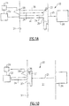
Figure 1A schematically shows an actuator system. -
Figure 1B shows an actuator system ofFigure 1A in a distinct location. -
Figure 2 is a flowchart. - A
system 20 includes amotor 22 for moving anactuator 24 to, in turn, move ashaft 25 to change a location of acomponent 26. Thecomponent 26 may be a moving system on an aircraft. It should be understood that this system may include linear movement, pivoting movement, rotating movement, or any number of combinations of such types of movement. This disclosure is not limited to the actuation system, nor to thecomponent 26 being controlled. - A
sensor 28, which may be a linear variable displacement transducer and, in particular, utilizing ultrasonic signals is positioned to monitor the location of the movingactuator 24. As shown, asignal 34 reflects off of asurface 30 that will eventually be a stop surface or a surface closest to the sensor at an end of travel position. - The
signal 34 reflects off thesurface 30 and returns to the sensor. Theactuator 24 is moving through amedium 21. In one application, the medium may be water. Of course, other fluids including fuel, air, oil, hydraulic fluid, a coolant or others may be used. -
Figure 1B shows an end of travel position where thesurface 30 is now bottomed out against anend wall 31. As theactuator 24 and, in particular,surface 30 get very close tosensor 28, it will be move within a minimum distance for accurate measurement. As mentioned above, when thesurface 30 is close to asensor 28, there can be interference between the outgoing and the reflected signals. - As mentioned, in an application wherein a 2.5 megahertz transducer is operating in a water medium, the minimum distance might be 5 millimeters. Of course, this is but an example. Many other combinations would benefit from this disclosure.
- Modern control systems need the ability to accurately measure the position to a fine degree (in this example, less than five millimeters). As such, movement within this minimum distance would be desirably sensed.
- Thus, a
step surface 32 is also formed spaced from thesurface 30 by a step dimension. Thestep surface 32 is generally selected to be at least beyond the minimum distance from thesensor 28 relative to thesurface 30. As thecomponent 24 approaches theFigure 1B position, thecontrol 29 switches thesensor 28 to measuring the distance to bothsurfaces control 29 can simply switch the sensor from measuring tosurface 30 to measuring tosurface 32. - The
control 29 is preferably programmed to ignore unstable signals, such as may be expected from thesurface 30 as it moves within this minimum distance. - Also, once a distance d between the
surfaces component 24, is known, sensing to thesurfaces - In particular, in a calibration mode, the sensor can send a signal off both
surfaces control 29 may determine that calibration is in order. - While the system is disclosed switching between the two surfaces, in at least a broadest sense, a method and apparatus might simply sense to a
target surface 32 that is far enough away from thesensor 28 at an end of travel position, that the minimum distance does not become a problem -
Figure 2 shows a flowchart having astep 100 of moving an actuator. A sensor monitors a distance to a target on the actuator. At 104, the distance is compared to a limit. In general, at 106, if the distance is less than a limit, then the control switch is to utilize a secondary surface at 106. On the other hand, if the distance is not less than the limit then the primary surface is utilized atstep 108. - As mentioned above, in one embodiment, at least during a portion of operation, the distance to both surfaces is monitored.
- A method of operating a system includes the steps of moving an actuator and sensing a distance to a first surface on the moving actuator. The sensor is operable to utilize the sensed distance as position feedback for a component moved by the actuator. The first surface is spaced from the sensor by a distance that is less than a minimum distance in an end of travel position. The said minimum distance is defined in view of a medium through which the moving actuator moves, and a frequency of a signal from the sensor. A signal is sent off of a second surface on the moving actuator that will be spaced from the sensor by a distance greater than the minimum distance when the actuator is in said end of travel position.
- Although an embodiment of this invention has been disclosed, a worker of ordinary skill in this art would recognize that certain modifications would come within the scope of this invention. For that reason, the following claims should be studied to determine the true scope and content of this invention.
Claims (15)
- A system (20) comprising:an actuator (24) having a first surface and a second surface, the first surface being offset a step dimension from the second surface; anda sensor (28) configured to measure a distance between the sensor (28) and both the first surface (30) and the second surface (32) via a signal received by the sensor (28) after having reflected off the first surface (30) or the second surface (32), wherein the step dimension is greater than a minimum dimension, the minimum dimension being defined in view of a medium through which said actuator moves and a frequency of the signal.
- The system as set forth in claim 1, wherein the first surface (30) is positionable nearer to the sensor (28) than the minimum dimension when the actuator (24) reaches an end of travel position.
- The system as set forth in claim 2, wherein said sensor (28) initially directing a signal off said first surface (30) for a period of time, and sending a signal off said second surface (32) at least when said first surface approaches the minimum distance from said sensor (28).
- The system as set forth in claim 3, wherein said sensor sends a signal off both said first (30) and said second surfaces (32) at least for a period of time as said first surface approaches said minimum distance.
- The system as set forth in claim 4, wherein said medium is water, and preferably wherein said actuator (24) moves a component associated with aircraft.
- The system as set forth in any preceding claim, wherein said sensor (28) initially directing a signal off said first surface (30) for a period of time, and sending a signal off said second surface (32) at least when said first surface (30) approaches the minimum distance from said sensor (28), and preferably wherein said sensor (28) sends a signal off both said first (30) and said second surfaces (32) at least for a period of time as said first surface approaches said minimum distance.
- The system as set forth in any preceding claim, wherein a control for said system (20) being programmed to know the step dimension, and to compare an apparent difference sensed between distances to said first and second surfaces to said step dimension, and determine whether calibration is in order based upon this comparison.
- The system as set forth in any preceding claim, wherein said actuator (24) moves a component associated with aircraft.
- A method of operating a system (20) comprising the steps of:moving an actuator (24) having a first surface (30) and a second surface (32), the first surface (30) offset from the second surface (32) by a step dimension;sensing a distance between a sensor (28) and both the first surface (30) and the second surface (32) via a signal received by the sensor (28) after having reflected off the first surface (30) or the second surface (32), wherein the step dimension is greater than a minimum dimension, the minimum dimension being defined in view of a medium through which said actuator (24) moves and a frequency of the signal.
- The method as set forth in claim 9, wherein the first surface (30) is positionable nearer to the sensor than the minimum dimension when the actuator (24) reaches an end of travel position.
- The method as set forth in claim 10, wherein said sensor (28) initially directing a signal off said first surface for a period of time, and sending a signal off said second surface at least when said first surface approaches the minimum distance from said sensor.
- The method as set forth in claim 11, wherein said sensor sends a signal off both said first and said second surfaces at least for a period of time as said first surface approaches said minimum distance, and preferably wherein said actuator moves a component associated with aircraft.
- The method as set forth in claim 9, 10, 11 or 12, wherein said sensor (28) initially directing a signal off said first surface for a period of time, and sending a signal off said second surface at least when said first surface approaches the minimum distance from said sensor, and/or wherein said actuator (24) moves a component associated with aircraft.
- The method as set forth in claim 13, wherein said sensor (28) sends a signal off both said first and said second surfaces at least for a period of time as said first surface approaches said minimum distance and/or wherein a control for said system being programmed to know the step dimension, and comparing an apparent difference sensed between distances to said first and second surfaces to said step dimension, and determine whether calibration is in order based upon this comparison.
- A system (20) comprising:a moving actuator (24);a sensor (28) for sensing a distance to a surface on said moving actuator (24), said sensor (28) being operable to utilize said distance as position feedback for a component being moved by said actuator (24); andthe surface being spaced from said sensor (28) by a distance that is greater than a minimum distance in an end-of-travel position, said minimum distance being defined in view of a medium through which said moving actuator (24) moves and a frequency of a signal from said sensor (28).
Applications Claiming Priority (1)
| Application Number | Priority Date | Filing Date | Title |
|---|---|---|---|
| US15/681,520 US10495740B2 (en) | 2017-08-21 | 2017-08-21 | Short range ultrasonic measurement |
Publications (2)
| Publication Number | Publication Date |
|---|---|
| EP3447526A1 true EP3447526A1 (en) | 2019-02-27 |
| EP3447526B1 EP3447526B1 (en) | 2024-08-07 |
Family
ID=63311879
Family Applications (1)
| Application Number | Title | Priority Date | Filing Date |
|---|---|---|---|
| EP18189692.9A Active EP3447526B1 (en) | 2017-08-21 | 2018-08-20 | Short range ultrasonic measurement |
Country Status (2)
| Country | Link |
|---|---|
| US (1) | US10495740B2 (en) |
| EP (1) | EP3447526B1 (en) |
Citations (3)
| Publication number | Priority date | Publication date | Assignee | Title |
|---|---|---|---|---|
| US4543649A (en) * | 1983-10-17 | 1985-09-24 | Teknar, Inc. | System for ultrasonically detecting the relative position of a moveable device |
| WO1990007721A1 (en) * | 1989-01-09 | 1990-07-12 | Motorola, Inc. | System for measuring position of an object using electronic or ultrasonic devices where the object contains a reference reflector for temperature compensation |
| WO2005003571A1 (en) * | 2003-07-04 | 2005-01-13 | Horst Siedle Gmbh & Co. Kg | Method for determining a current position of a piston movably accommodated in a cylinder |
Family Cites Families (17)
| Publication number | Priority date | Publication date | Assignee | Title |
|---|---|---|---|---|
| US4008455A (en) * | 1975-02-24 | 1977-02-15 | Westinghouse Electric Corporation | Method of making self-calibrated displacement measurements |
| US4769793A (en) * | 1985-07-24 | 1988-09-06 | Ultrasonic Arrays, Inc. | Dual reference surface transducer |
| US4938054A (en) * | 1989-05-03 | 1990-07-03 | Gilbarco Inc. | Ultrasonic linear meter sensor for positive displacement meter |
| US5095754A (en) * | 1989-07-12 | 1992-03-17 | Jeffrey A. Simpson | Apparatus and method for detection of icing onset and ice thickness |
| US6142059A (en) * | 1996-11-27 | 2000-11-07 | Case Corporation | Method and apparatus for sensing the orientation of a mechanical actuator |
| US5917776A (en) | 1996-12-31 | 1999-06-29 | Honeywell Inc. | Means for reducing minimum sensing distance of an ultrasonic proximity sensor |
| US6119579A (en) * | 1998-03-20 | 2000-09-19 | Caterpillar Inc. | Apparatus and method for detecting piston location within a fluid cylinder of a work machine |
| JP2001065513A (en) * | 1999-08-26 | 2001-03-16 | Toyota Autom Loom Works Ltd | Hydraulic cylinder position detection device and industrial vehicle provided therewith |
| US7377169B2 (en) * | 2004-04-09 | 2008-05-27 | Shell Oil Company | Apparatus and methods for acoustically determining fluid properties while sampling |
| DE102007035252A1 (en) * | 2007-07-27 | 2009-02-12 | Truma Gerätetechnik GmbH & Co. KG | Device for determining the position of a piston in a cylinder |
| EP2105738A3 (en) | 2008-03-25 | 2011-09-28 | Siemens Aktiengesellschaft | Calibration for a system to check materials without destroying them |
| US9151840B2 (en) | 2012-03-09 | 2015-10-06 | Semiconductor Components Industries, Llc | Semiconductor device and method of forming same for acoustic sensing of close proximity objects |
| US9163471B2 (en) * | 2012-04-27 | 2015-10-20 | Cameron International Corporation | Position monitoring system and method |
| US9187974B2 (en) * | 2012-04-27 | 2015-11-17 | Cameron International Corporation | System and method for position monitoring using ultrasonic sensor |
| US9804039B2 (en) * | 2012-04-27 | 2017-10-31 | Cameron International Corporation | System and method for position monitoring using ultrasonic sensor |
| EP3736604A1 (en) | 2014-04-11 | 2020-11-11 | SZ DJI Technology Co., Ltd. | Proximity sensing systems and methods |
| US10365247B2 (en) * | 2016-09-12 | 2019-07-30 | Hamilton Sundstrand Corporation | Movable member assembly having a sensor assembly |
-
2017
- 2017-08-21 US US15/681,520 patent/US10495740B2/en active Active
-
2018
- 2018-08-20 EP EP18189692.9A patent/EP3447526B1/en active Active
Patent Citations (3)
| Publication number | Priority date | Publication date | Assignee | Title |
|---|---|---|---|---|
| US4543649A (en) * | 1983-10-17 | 1985-09-24 | Teknar, Inc. | System for ultrasonically detecting the relative position of a moveable device |
| WO1990007721A1 (en) * | 1989-01-09 | 1990-07-12 | Motorola, Inc. | System for measuring position of an object using electronic or ultrasonic devices where the object contains a reference reflector for temperature compensation |
| WO2005003571A1 (en) * | 2003-07-04 | 2005-01-13 | Horst Siedle Gmbh & Co. Kg | Method for determining a current position of a piston movably accommodated in a cylinder |
Also Published As
| Publication number | Publication date |
|---|---|
| US10495740B2 (en) | 2019-12-03 |
| US20190056485A1 (en) | 2019-02-21 |
| EP3447526B1 (en) | 2024-08-07 |
Similar Documents
| Publication | Publication Date | Title |
|---|---|---|
| US20100288036A1 (en) | Device for determining the position of a piston in a cylinder | |
| CA1226661A (en) | System for ultrasonically detecting the relative position of a moveable device | |
| EP3115755B1 (en) | System and method for measuring a speed of sound in a liquid or gaseous medium | |
| US7889119B2 (en) | Radial gap measurement on turbines | |
| EP4193124B1 (en) | Ultrasonic position sensor | |
| US10473759B2 (en) | Tool for automatic multiple radar calibration | |
| EP2839241B1 (en) | Method of finding a feature of an object using a machine tool and corresponding machine tool apparatus | |
| CN115398264B (en) | Radar transceiver test methods and systems | |
| EP3447526B1 (en) | Short range ultrasonic measurement | |
| EP3874236B1 (en) | Method and device to measure the velocity of a fluid flowing in a confined space | |
| US11098771B2 (en) | Method and device for determining the travel of a clutch or a gear actuator in a hydraulic clutch actuation system or a hydraulic gear actuation system | |
| EP3559605B1 (en) | Apparatus and method for measuring air flow | |
| EP3293497B1 (en) | Movable member assembly having a sensor assembly | |
| US8814065B2 (en) | Nozzle unit for applying damping material, and damping material application apparatus | |
| EP3808994A1 (en) | Performance enhancement of controllers for varying temperature conditions in hydraulic actuators | |
| US12085190B2 (en) | Measuring system, slide valve comprising such a measuring system, and method for measuring the position of a slide valve | |
| EP3744987A1 (en) | Ultrasonic position detection temperature calibration | |
| US20130182540A1 (en) | Position sensor | |
| EP3649441B1 (en) | Apparatus and method for measuring air flow | |
| US20120001792A1 (en) | Measuring device with a measuring section and a reference section | |
| EP3569889B1 (en) | Platform for testing a distance-measuring device under air pressure | |
| US12098937B2 (en) | Measuring channel and process for spatially arranging a sensor component or sensor array in a measuring channel | |
| WO2004041473A1 (en) | Lasere machining device with ultrasound system for controlling the distance between the laser head and the workpiece | |
| CN109923377B (en) | Signal processing circuit, related chip, flowmeter and method | |
| EP3327448A1 (en) | Scanning probe microscopy system, and method for probe exchange therein |
Legal Events
| Date | Code | Title | Description |
|---|---|---|---|
| PUAI | Public reference made under article 153(3) epc to a published international application that has entered the european phase |
Free format text: ORIGINAL CODE: 0009012 |
|
| STAA | Information on the status of an ep patent application or granted ep patent |
Free format text: STATUS: THE APPLICATION HAS BEEN PUBLISHED |
|
| AK | Designated contracting states |
Kind code of ref document: A1 Designated state(s): AL AT BE BG CH CY CZ DE DK EE ES FI FR GB GR HR HU IE IS IT LI LT LU LV MC MK MT NL NO PL PT RO RS SE SI SK SM TR |
|
| AX | Request for extension of the european patent |
Extension state: BA ME |
|
| STAA | Information on the status of an ep patent application or granted ep patent |
Free format text: STATUS: REQUEST FOR EXAMINATION WAS MADE |
|
| 17P | Request for examination filed |
Effective date: 20190808 |
|
| RBV | Designated contracting states (corrected) |
Designated state(s): AL AT BE BG CH CY CZ DE DK EE ES FI FR GB GR HR HU IE IS IT LI LT LU LV MC MK MT NL NO PL PT RO RS SE SI SK SM TR |
|
| STAA | Information on the status of an ep patent application or granted ep patent |
Free format text: STATUS: EXAMINATION IS IN PROGRESS |
|
| 17Q | First examination report despatched |
Effective date: 20210528 |
|
| GRAP | Despatch of communication of intention to grant a patent |
Free format text: ORIGINAL CODE: EPIDOSNIGR1 |
|
| STAA | Information on the status of an ep patent application or granted ep patent |
Free format text: STATUS: GRANT OF PATENT IS INTENDED |
|
| INTG | Intention to grant announced |
Effective date: 20231006 |
|
| GRAJ | Information related to disapproval of communication of intention to grant by the applicant or resumption of examination proceedings by the epo deleted |
Free format text: ORIGINAL CODE: EPIDOSDIGR1 |
|
| STAA | Information on the status of an ep patent application or granted ep patent |
Free format text: STATUS: EXAMINATION IS IN PROGRESS |
|
| GRAP | Despatch of communication of intention to grant a patent |
Free format text: ORIGINAL CODE: EPIDOSNIGR1 |
|
| STAA | Information on the status of an ep patent application or granted ep patent |
Free format text: STATUS: GRANT OF PATENT IS INTENDED |
|
| INTC | Intention to grant announced (deleted) | ||
| INTG | Intention to grant announced |
Effective date: 20240306 |
|
| GRAS | Grant fee paid |
Free format text: ORIGINAL CODE: EPIDOSNIGR3 |
|
| GRAA | (expected) grant |
Free format text: ORIGINAL CODE: 0009210 |
|
| STAA | Information on the status of an ep patent application or granted ep patent |
Free format text: STATUS: THE PATENT HAS BEEN GRANTED |
|
| AK | Designated contracting states |
Kind code of ref document: B1 Designated state(s): AL AT BE BG CH CY CZ DE DK EE ES FI FR GB GR HR HU IE IS IT LI LT LU LV MC MK MT NL NO PL PT RO RS SE SI SK SM TR |
|
| REG | Reference to a national code |
Ref country code: GB Ref legal event code: FG4D |
|
| REG | Reference to a national code |
Ref country code: CH Ref legal event code: EP |
|
| REG | Reference to a national code |
Ref country code: IE Ref legal event code: FG4D |
|
| REG | Reference to a national code |
Ref country code: DE Ref legal event code: R096 Ref document number: 602018072680 Country of ref document: DE |
|
| REG | Reference to a national code |
Ref country code: LT Ref legal event code: MG9D |
|
| REG | Reference to a national code |
Ref country code: NL Ref legal event code: MP Effective date: 20240807 |
|
| PG25 | Lapsed in a contracting state [announced via postgrant information from national office to epo] |
Ref country code: NO Free format text: LAPSE BECAUSE OF FAILURE TO SUBMIT A TRANSLATION OF THE DESCRIPTION OR TO PAY THE FEE WITHIN THE PRESCRIBED TIME-LIMIT Effective date: 20241107 |
|
| REG | Reference to a national code |
Ref country code: AT Ref legal event code: MK05 Ref document number: 1711546 Country of ref document: AT Kind code of ref document: T Effective date: 20240807 |
|
| PG25 | Lapsed in a contracting state [announced via postgrant information from national office to epo] |
Ref country code: NL Free format text: LAPSE BECAUSE OF FAILURE TO SUBMIT A TRANSLATION OF THE DESCRIPTION OR TO PAY THE FEE WITHIN THE PRESCRIBED TIME-LIMIT Effective date: 20240807 Ref country code: FI Free format text: LAPSE BECAUSE OF FAILURE TO SUBMIT A TRANSLATION OF THE DESCRIPTION OR TO PAY THE FEE WITHIN THE PRESCRIBED TIME-LIMIT Effective date: 20240807 Ref country code: PT Free format text: LAPSE BECAUSE OF FAILURE TO SUBMIT A TRANSLATION OF THE DESCRIPTION OR TO PAY THE FEE WITHIN THE PRESCRIBED TIME-LIMIT Effective date: 20241209 Ref country code: GR Free format text: LAPSE BECAUSE OF FAILURE TO SUBMIT A TRANSLATION OF THE DESCRIPTION OR TO PAY THE FEE WITHIN THE PRESCRIBED TIME-LIMIT Effective date: 20241108 Ref country code: PL Free format text: LAPSE BECAUSE OF FAILURE TO SUBMIT A TRANSLATION OF THE DESCRIPTION OR TO PAY THE FEE WITHIN THE PRESCRIBED TIME-LIMIT Effective date: 20240807 |
|
| PG25 | Lapsed in a contracting state [announced via postgrant information from national office to epo] |
Ref country code: BG Free format text: LAPSE BECAUSE OF FAILURE TO SUBMIT A TRANSLATION OF THE DESCRIPTION OR TO PAY THE FEE WITHIN THE PRESCRIBED TIME-LIMIT Effective date: 20240807 |
|
| PG25 | Lapsed in a contracting state [announced via postgrant information from national office to epo] |
Ref country code: LV Free format text: LAPSE BECAUSE OF FAILURE TO SUBMIT A TRANSLATION OF THE DESCRIPTION OR TO PAY THE FEE WITHIN THE PRESCRIBED TIME-LIMIT Effective date: 20240807 |
|
| PG25 | Lapsed in a contracting state [announced via postgrant information from national office to epo] |
Ref country code: AT Free format text: LAPSE BECAUSE OF FAILURE TO SUBMIT A TRANSLATION OF THE DESCRIPTION OR TO PAY THE FEE WITHIN THE PRESCRIBED TIME-LIMIT Effective date: 20240807 Ref country code: IS Free format text: LAPSE BECAUSE OF FAILURE TO SUBMIT A TRANSLATION OF THE DESCRIPTION OR TO PAY THE FEE WITHIN THE PRESCRIBED TIME-LIMIT Effective date: 20241207 |
|
| PG25 | Lapsed in a contracting state [announced via postgrant information from national office to epo] |
Ref country code: HR Free format text: LAPSE BECAUSE OF FAILURE TO SUBMIT A TRANSLATION OF THE DESCRIPTION OR TO PAY THE FEE WITHIN THE PRESCRIBED TIME-LIMIT Effective date: 20240807 |
|
| PG25 | Lapsed in a contracting state [announced via postgrant information from national office to epo] |
Ref country code: RS Free format text: LAPSE BECAUSE OF FAILURE TO SUBMIT A TRANSLATION OF THE DESCRIPTION OR TO PAY THE FEE WITHIN THE PRESCRIBED TIME-LIMIT Effective date: 20241107 Ref country code: ES Free format text: LAPSE BECAUSE OF FAILURE TO SUBMIT A TRANSLATION OF THE DESCRIPTION OR TO PAY THE FEE WITHIN THE PRESCRIBED TIME-LIMIT Effective date: 20240807 |
|
| PG25 | Lapsed in a contracting state [announced via postgrant information from national office to epo] |
Ref country code: RS Free format text: LAPSE BECAUSE OF FAILURE TO SUBMIT A TRANSLATION OF THE DESCRIPTION OR TO PAY THE FEE WITHIN THE PRESCRIBED TIME-LIMIT Effective date: 20241107 Ref country code: PT Free format text: LAPSE BECAUSE OF FAILURE TO SUBMIT A TRANSLATION OF THE DESCRIPTION OR TO PAY THE FEE WITHIN THE PRESCRIBED TIME-LIMIT Effective date: 20241209 Ref country code: PL Free format text: LAPSE BECAUSE OF FAILURE TO SUBMIT A TRANSLATION OF THE DESCRIPTION OR TO PAY THE FEE WITHIN THE PRESCRIBED TIME-LIMIT Effective date: 20240807 Ref country code: NO Free format text: LAPSE BECAUSE OF FAILURE TO SUBMIT A TRANSLATION OF THE DESCRIPTION OR TO PAY THE FEE WITHIN THE PRESCRIBED TIME-LIMIT Effective date: 20241107 Ref country code: NL Free format text: LAPSE BECAUSE OF FAILURE TO SUBMIT A TRANSLATION OF THE DESCRIPTION OR TO PAY THE FEE WITHIN THE PRESCRIBED TIME-LIMIT Effective date: 20240807 Ref country code: LV Free format text: LAPSE BECAUSE OF FAILURE TO SUBMIT A TRANSLATION OF THE DESCRIPTION OR TO PAY THE FEE WITHIN THE PRESCRIBED TIME-LIMIT Effective date: 20240807 Ref country code: IS Free format text: LAPSE BECAUSE OF FAILURE TO SUBMIT A TRANSLATION OF THE DESCRIPTION OR TO PAY THE FEE WITHIN THE PRESCRIBED TIME-LIMIT Effective date: 20241207 Ref country code: HR Free format text: LAPSE BECAUSE OF FAILURE TO SUBMIT A TRANSLATION OF THE DESCRIPTION OR TO PAY THE FEE WITHIN THE PRESCRIBED TIME-LIMIT Effective date: 20240807 Ref country code: GR Free format text: LAPSE BECAUSE OF FAILURE TO SUBMIT A TRANSLATION OF THE DESCRIPTION OR TO PAY THE FEE WITHIN THE PRESCRIBED TIME-LIMIT Effective date: 20241108 Ref country code: FI Free format text: LAPSE BECAUSE OF FAILURE TO SUBMIT A TRANSLATION OF THE DESCRIPTION OR TO PAY THE FEE WITHIN THE PRESCRIBED TIME-LIMIT Effective date: 20240807 Ref country code: ES Free format text: LAPSE BECAUSE OF FAILURE TO SUBMIT A TRANSLATION OF THE DESCRIPTION OR TO PAY THE FEE WITHIN THE PRESCRIBED TIME-LIMIT Effective date: 20240807 Ref country code: BG Free format text: LAPSE BECAUSE OF FAILURE TO SUBMIT A TRANSLATION OF THE DESCRIPTION OR TO PAY THE FEE WITHIN THE PRESCRIBED TIME-LIMIT Effective date: 20240807 Ref country code: AT Free format text: LAPSE BECAUSE OF FAILURE TO SUBMIT A TRANSLATION OF THE DESCRIPTION OR TO PAY THE FEE WITHIN THE PRESCRIBED TIME-LIMIT Effective date: 20240807 |
|
| REG | Reference to a national code |
Ref country code: CH Ref legal event code: PL |
|
| PG25 | Lapsed in a contracting state [announced via postgrant information from national office to epo] |
Ref country code: DK Free format text: LAPSE BECAUSE OF FAILURE TO SUBMIT A TRANSLATION OF THE DESCRIPTION OR TO PAY THE FEE WITHIN THE PRESCRIBED TIME-LIMIT Effective date: 20240807 Ref country code: SM Free format text: LAPSE BECAUSE OF FAILURE TO SUBMIT A TRANSLATION OF THE DESCRIPTION OR TO PAY THE FEE WITHIN THE PRESCRIBED TIME-LIMIT Effective date: 20240807 Ref country code: RO Free format text: LAPSE BECAUSE OF FAILURE TO SUBMIT A TRANSLATION OF THE DESCRIPTION OR TO PAY THE FEE WITHIN THE PRESCRIBED TIME-LIMIT Effective date: 20240807 |
|
| PG25 | Lapsed in a contracting state [announced via postgrant information from national office to epo] |
Ref country code: LU Free format text: LAPSE BECAUSE OF NON-PAYMENT OF DUE FEES Effective date: 20240820 |
|
| PG25 | Lapsed in a contracting state [announced via postgrant information from national office to epo] |
Ref country code: CH Free format text: LAPSE BECAUSE OF NON-PAYMENT OF DUE FEES Effective date: 20240831 Ref country code: EE Free format text: LAPSE BECAUSE OF FAILURE TO SUBMIT A TRANSLATION OF THE DESCRIPTION OR TO PAY THE FEE WITHIN THE PRESCRIBED TIME-LIMIT Effective date: 20240807 |
|
| PG25 | Lapsed in a contracting state [announced via postgrant information from national office to epo] |
Ref country code: CZ Free format text: LAPSE BECAUSE OF FAILURE TO SUBMIT A TRANSLATION OF THE DESCRIPTION OR TO PAY THE FEE WITHIN THE PRESCRIBED TIME-LIMIT Effective date: 20240807 |
|
| PG25 | Lapsed in a contracting state [announced via postgrant information from national office to epo] |
Ref country code: SK Free format text: LAPSE BECAUSE OF FAILURE TO SUBMIT A TRANSLATION OF THE DESCRIPTION OR TO PAY THE FEE WITHIN THE PRESCRIBED TIME-LIMIT Effective date: 20240807 |
|
| REG | Reference to a national code |
Ref country code: DE Ref legal event code: R097 Ref document number: 602018072680 Country of ref document: DE |
|
| PLBE | No opposition filed within time limit |
Free format text: ORIGINAL CODE: 0009261 |
|
| STAA | Information on the status of an ep patent application or granted ep patent |
Free format text: STATUS: NO OPPOSITION FILED WITHIN TIME LIMIT |
|
| REG | Reference to a national code |
Ref country code: BE Ref legal event code: MM Effective date: 20240831 |
|
| PG25 | Lapsed in a contracting state [announced via postgrant information from national office to epo] |
Ref country code: MC Free format text: LAPSE BECAUSE OF FAILURE TO SUBMIT A TRANSLATION OF THE DESCRIPTION OR TO PAY THE FEE WITHIN THE PRESCRIBED TIME-LIMIT Effective date: 20240807 |
|
| PG25 | Lapsed in a contracting state [announced via postgrant information from national office to epo] |
Ref country code: BE Free format text: LAPSE BECAUSE OF NON-PAYMENT OF DUE FEES Effective date: 20240831 |
|
| 26N | No opposition filed |
Effective date: 20250508 |
|
| PG25 | Lapsed in a contracting state [announced via postgrant information from national office to epo] |
Ref country code: IE Free format text: LAPSE BECAUSE OF NON-PAYMENT OF DUE FEES Effective date: 20240820 |
|
| PG25 | Lapsed in a contracting state [announced via postgrant information from national office to epo] |
Ref country code: SE Free format text: LAPSE BECAUSE OF FAILURE TO SUBMIT A TRANSLATION OF THE DESCRIPTION OR TO PAY THE FEE WITHIN THE PRESCRIBED TIME-LIMIT Effective date: 20240807 |
|
| PGFP | Annual fee paid to national office [announced via postgrant information from national office to epo] |
Ref country code: DE Payment date: 20250724 Year of fee payment: 8 |
|
| PGFP | Annual fee paid to national office [announced via postgrant information from national office to epo] |
Ref country code: GB Payment date: 20250724 Year of fee payment: 8 |
|
| PGFP | Annual fee paid to national office [announced via postgrant information from national office to epo] |
Ref country code: FR Payment date: 20250725 Year of fee payment: 8 |
|
| PG25 | Lapsed in a contracting state [announced via postgrant information from national office to epo] |
Ref country code: IT Free format text: LAPSE BECAUSE OF FAILURE TO SUBMIT A TRANSLATION OF THE DESCRIPTION OR TO PAY THE FEE WITHIN THE PRESCRIBED TIME-LIMIT Effective date: 20240807 Ref country code: CY Free format text: LAPSE BECAUSE OF FAILURE TO SUBMIT A TRANSLATION OF THE DESCRIPTION OR TO PAY THE FEE WITHIN THE PRESCRIBED TIME-LIMIT; INVALID AB INITIO Effective date: 20180820 |
|
| PG25 | Lapsed in a contracting state [announced via postgrant information from national office to epo] |
Ref country code: HU Free format text: LAPSE BECAUSE OF FAILURE TO SUBMIT A TRANSLATION OF THE DESCRIPTION OR TO PAY THE FEE WITHIN THE PRESCRIBED TIME-LIMIT; INVALID AB INITIO Effective date: 20180820 |