EP3447498A1 - Liquid dispensing apparatus and system - Google Patents
Liquid dispensing apparatus and system Download PDFInfo
- Publication number
- EP3447498A1 EP3447498A1 EP18189604.4A EP18189604A EP3447498A1 EP 3447498 A1 EP3447498 A1 EP 3447498A1 EP 18189604 A EP18189604 A EP 18189604A EP 3447498 A1 EP3447498 A1 EP 3447498A1
- Authority
- EP
- European Patent Office
- Prior art keywords
- liquid
- discharging device
- chemical liquid
- use history
- liquid discharging
- Prior art date
- Legal status (The legal status is an assumption and is not a legal conclusion. Google has not performed a legal analysis and makes no representation as to the accuracy of the status listed.)
- Granted
Links
Images


Classifications
-
- B—PERFORMING OPERATIONS; TRANSPORTING
- B05—SPRAYING OR ATOMISING IN GENERAL; APPLYING FLUENT MATERIALS TO SURFACES, IN GENERAL
- B05B—SPRAYING APPARATUS; ATOMISING APPARATUS; NOZZLES
- B05B12/00—Arrangements for controlling delivery; Arrangements for controlling the spray area
- B05B12/004—Arrangements for controlling delivery; Arrangements for controlling the spray area comprising sensors for monitoring the delivery, e.g. by displaying the sensed value or generating an alarm
-
- G—PHYSICS
- G01—MEASURING; TESTING
- G01N—INVESTIGATING OR ANALYSING MATERIALS BY DETERMINING THEIR CHEMICAL OR PHYSICAL PROPERTIES
- G01N35/00—Automatic analysis not limited to methods or materials provided for in any single one of groups G01N1/00 - G01N33/00; Handling materials therefor
- G01N35/00584—Control arrangements for automatic analysers
-
- G—PHYSICS
- G01—MEASURING; TESTING
- G01N—INVESTIGATING OR ANALYSING MATERIALS BY DETERMINING THEIR CHEMICAL OR PHYSICAL PROPERTIES
- G01N35/00—Automatic analysis not limited to methods or materials provided for in any single one of groups G01N1/00 - G01N33/00; Handling materials therefor
- G01N35/00584—Control arrangements for automatic analysers
- G01N35/00594—Quality control, including calibration or testing of components of the analyser
- G01N35/00613—Quality control
- G01N35/00623—Quality control of instruments
-
- G—PHYSICS
- G01—MEASURING; TESTING
- G01N—INVESTIGATING OR ANALYSING MATERIALS BY DETERMINING THEIR CHEMICAL OR PHYSICAL PROPERTIES
- G01N35/00—Automatic analysis not limited to methods or materials provided for in any single one of groups G01N1/00 - G01N33/00; Handling materials therefor
- G01N35/00584—Control arrangements for automatic analysers
- G01N35/00722—Communications; Identification
- G01N35/00732—Identification of carriers, materials or components in automatic analysers
-
- G—PHYSICS
- G01—MEASURING; TESTING
- G01N—INVESTIGATING OR ANALYSING MATERIALS BY DETERMINING THEIR CHEMICAL OR PHYSICAL PROPERTIES
- G01N35/00—Automatic analysis not limited to methods or materials provided for in any single one of groups G01N1/00 - G01N33/00; Handling materials therefor
- G01N35/00584—Control arrangements for automatic analysers
- G01N35/00722—Communications; Identification
- G01N35/00871—Communications between instruments or with remote terminals
-
- G—PHYSICS
- G01—MEASURING; TESTING
- G01N—INVESTIGATING OR ANALYSING MATERIALS BY DETERMINING THEIR CHEMICAL OR PHYSICAL PROPERTIES
- G01N35/00—Automatic analysis not limited to methods or materials provided for in any single one of groups G01N1/00 - G01N33/00; Handling materials therefor
- G01N35/10—Devices for transferring samples or any liquids to, in, or from, the analysis apparatus, e.g. suction devices, injection devices
- G01N35/1009—Characterised by arrangements for controlling the aspiration or dispense of liquids
-
- G—PHYSICS
- G01—MEASURING; TESTING
- G01N—INVESTIGATING OR ANALYSING MATERIALS BY DETERMINING THEIR CHEMICAL OR PHYSICAL PROPERTIES
- G01N35/00—Automatic analysis not limited to methods or materials provided for in any single one of groups G01N1/00 - G01N33/00; Handling materials therefor
- G01N35/00584—Control arrangements for automatic analysers
- G01N35/00722—Communications; Identification
- G01N35/00732—Identification of carriers, materials or components in automatic analysers
- G01N2035/00742—Type of codes
- G01N2035/00782—Type of codes reprogrammmable code
-
- G—PHYSICS
- G01—MEASURING; TESTING
- G01N—INVESTIGATING OR ANALYSING MATERIALS BY DETERMINING THEIR CHEMICAL OR PHYSICAL PROPERTIES
- G01N35/00—Automatic analysis not limited to methods or materials provided for in any single one of groups G01N1/00 - G01N33/00; Handling materials therefor
- G01N35/00584—Control arrangements for automatic analysers
- G01N35/00722—Communications; Identification
- G01N35/00732—Identification of carriers, materials or components in automatic analysers
- G01N2035/00792—Type of components bearing the codes, other than sample carriers
- G01N2035/00811—Type of components bearing the codes, other than sample carriers consumable or exchangeable components other than sample carriers, e.g. detectors, flow cells
-
- G—PHYSICS
- G01—MEASURING; TESTING
- G01N—INVESTIGATING OR ANALYSING MATERIALS BY DETERMINING THEIR CHEMICAL OR PHYSICAL PROPERTIES
- G01N35/00—Automatic analysis not limited to methods or materials provided for in any single one of groups G01N1/00 - G01N33/00; Handling materials therefor
- G01N35/00584—Control arrangements for automatic analysers
- G01N35/00722—Communications; Identification
- G01N2035/00891—Displaying information to the operator
-
- G—PHYSICS
- G01—MEASURING; TESTING
- G01N—INVESTIGATING OR ANALYSING MATERIALS BY DETERMINING THEIR CHEMICAL OR PHYSICAL PROPERTIES
- G01N35/00—Automatic analysis not limited to methods or materials provided for in any single one of groups G01N1/00 - G01N33/00; Handling materials therefor
- G01N35/00584—Control arrangements for automatic analysers
- G01N35/00722—Communications; Identification
- G01N2035/00891—Displaying information to the operator
- G01N2035/009—Displaying information to the operator alarms, e.g. audible
-
- G—PHYSICS
- G01—MEASURING; TESTING
- G01N—INVESTIGATING OR ANALYSING MATERIALS BY DETERMINING THEIR CHEMICAL OR PHYSICAL PROPERTIES
- G01N35/00—Automatic analysis not limited to methods or materials provided for in any single one of groups G01N1/00 - G01N33/00; Handling materials therefor
- G01N35/10—Devices for transferring samples or any liquids to, in, or from, the analysis apparatus, e.g. suction devices, injection devices
- G01N2035/1027—General features of the devices
- G01N2035/103—General features of the devices using disposable tips
-
- G—PHYSICS
- G01—MEASURING; TESTING
- G01N—INVESTIGATING OR ANALYSING MATERIALS BY DETERMINING THEIR CHEMICAL OR PHYSICAL PROPERTIES
- G01N35/00—Automatic analysis not limited to methods or materials provided for in any single one of groups G01N1/00 - G01N33/00; Handling materials therefor
- G01N35/10—Devices for transferring samples or any liquids to, in, or from, the analysis apparatus, e.g. suction devices, injection devices
- G01N2035/1027—General features of the devices
- G01N2035/1034—Transferring microquantities of liquid
- G01N2035/1041—Ink-jet like dispensers
-
- G—PHYSICS
- G01—MEASURING; TESTING
- G01N—INVESTIGATING OR ANALYSING MATERIALS BY DETERMINING THEIR CHEMICAL OR PHYSICAL PROPERTIES
- G01N35/00—Automatic analysis not limited to methods or materials provided for in any single one of groups G01N1/00 - G01N33/00; Handling materials therefor
- G01N35/10—Devices for transferring samples or any liquids to, in, or from, the analysis apparatus, e.g. suction devices, injection devices
- G01N35/1081—Devices for transferring samples or any liquids to, in, or from, the analysis apparatus, e.g. suction devices, injection devices characterised by the means for relatively moving the transfer device and the containers in an horizontal plane
- G01N35/1083—Devices for transferring samples or any liquids to, in, or from, the analysis apparatus, e.g. suction devices, injection devices characterised by the means for relatively moving the transfer device and the containers in an horizontal plane with one horizontal degree of freedom
Definitions
- Embodiments described herein relate generally to a liquid dispensing apparatus and a system.
- a liquid is dispensed through a liquid discharging device.
- the liquid discharging device can be detachable from the liquid dispensing apparatus so that it can be discarded after a single use to prevent contamination.
- a liquid dispensing apparatus comprising:
- the apparatus may further comprise:
- the reader may read a code on the liquid discharging device.
- control unit may further be configured to cause the use history stored in the external device to change so as to indicate that the liquid discharging device has been used once the control unit causes the driving circuit to supply the discharge voltage to the liquid discharging device.
- control unit may further be configured to cause the use history stored in the external device to change so as to indicate that the liquid discharging device has been used when the control unit detects that a liquid holding container of the liquid discharging device has been filled with the liquid.
- the actuator may comprise a piezoelectric film.
- the actuator may be a heater.
- a liquid discharging system comprising:
- system may further comprise:
- the first control unit may further be configured to cause the use history stored in the information processing device to change so as to indicate that the liquid discharging device has been used once the first control unit causes the driving circuit to supply the discharge voltage to the liquid discharging device.
- the first control unit may further be configured to cause the use history stored in the information processing device to change so as to indicate that the liquid discharging device has been used when the first control unit detects that a liquid holding container of the liquid discharging device has been filled with the liquid.
- the actuator may comprise a piezoelectric film.
- the actuator may be a heater.
- a method for discharging a liquid from a liquid dispensing device comprising:
- the method may further comprise: transmitting a signal indicating that the liquid discharging device has been previously used when the use history indicates that the liquid dispensing device has been previously used.
- the driving circuit may supply a discharge voltage to the actuator in response to the first control signal.
- the second control signal may be supplied when the driving circuit supplies the discharge voltage to the actuator.
- the second control signal may be supplied when a liquid holding container of the liquid discharging device has been filled with the liquid.
- the actuator may comprise a piezoelectric film.
- the actuator may be a heater.
- a liquid dispensing apparatus includes a base to which a liquid discharging device for discharging a liquid is mounted, an interface configured to communicate with an external device, a driving circuit to supply driving voltages to an actuator of the liquid discharging device, and a control unit configured to acquire a use history of the liquid discharging device from the external device through the interface, and cause the driving circuit to supply a discharge voltage to the actuator if the acquired use history indicates the liquid discharging device has not been used.
- liquid dispensing apparatuses and liquid discharging systems according to certain example embodiments will be described with reference to the drawings.
- the particular embodiments explained below are some possible examples of liquid dispensing apparatuses and chemical liquid discharging systems according to the present disclosure and do not limit the possible configurations, specifications, or the like of liquid dispensing apparatuses and liquid discharging systems according to the present disclosure.
- the drawings are schematic and are in some instances drawn with exaggeration and omissions for purposes of explanatory convenience. In general, components are not drawn to scale. The number of components, the dimensional ratio between different components, or the like does not necessarily match between different drawings or to actual devices.
- a discharging system discharges a predetermined liquid by a piezo jet method.
- the discharging system discharges several picoliters (pL) to several microliters ( ⁇ L) of a liquid into a microplate, a multi-well plate, or the like according to a user operation.
- the discharging system is used in a laboratory in a technical field such as biology, chemistry, or pharmacy research.
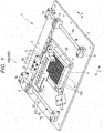
- Fig. 1 is a schematic perspective view of the discharging system 500.
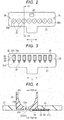
- Fig. 2 is a top view of a chemical liquid discharging device 2.
- Fig. 3 is a bottom view of a surface of the chemical liquid discharging device 2 from which a liquid is discharged.
- Fig. 4 is a cross-sectional view taken along a line F4-F4 in Fig. 2 .
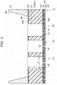
- Fig. 5 is a cross-sectional view taken along a line F5-F5 in Fig. 4 .
- the discharging system 500 includes a chemical liquid dispensing apparatus 1, the chemical liquid discharging device 2, a host computer 18, a server 50 (also referred to as an information processing device or external device), and the like.
- the discharging system 500 may have more elements in addition to the elements depicted in Fig. 1 , or some of the elements depicted in Fig. 1 may be omitted in some embodiments.
- the chemical liquid dispensing apparatus 1 controls the chemical liquid discharging device 2 to dispense a liquid from the chemical liquid discharging device 2.
- the chemical liquid dispensing apparatus 1 includes a base 3 of a rectangular flat plate shape, and a mounting module 5 that mounts the chemical liquid discharging device 2.
- the chemical liquid dispensing apparatus 1 dispenses the liquid into a microplate 4 having 1536 wells.
- the front to rear direction of the base 3 is referred to as an X direction
- the right to left direction of the base 3 is referred to as a Y direction.
- the X direction and the Y direction are orthogonal.
- the microplate 4 is fixed to the base 3.
- the microplate 4 includes a plurality of wells 300.
- Each well 300 of the microplate 4 holds a predetermined volume of a liquid.
- the liquids in the microplate can be chemicals, reagents, solutions, solvents, or the like and/or may include cells, blood cells, bacteria, plasma, antibodies, DNA, nucleic acids or proteins.
- the chemical liquid dispensing apparatus 1 includes a pair of right and left X direction guide rails 6a and 6b extending in the X direction on both sides of the microplate 4 on the base 3. Both ends each of the X direction guide rails 6a and 6b are fixed to fixing bases 7a and 7b protruding on the base 3.
- a Y direction guide rail 8 extending in the Y direction is installed between the X direction guide rails 6a and 6b. Both ends of the Y direction guide rail 8 are fixed to an X direction moving base 9 that is slidable in the X direction along the X direction guide rails 6a and 6b, respectively.
- the Y direction guide rail 8 includes a Y direction moving base 10 that allows a mounting module 5 to move in the Y direction along the Y direction guide rail 8.
- the mounting module 5 is mounted on the Y direction moving base 10.
- the chemical liquid discharging device 2 is fixed to the mounting module 5.
- the chemical liquid discharging device 2 is supported so as to be movable to an arbitrary position in the XY directions orthogonal to each other by a combination of an operation of a movement in the Y direction moving base 10 along the Y direction guide rail 8 in the Y direction and an operation of a movement in the X direction moving base 9 along the X direction guide rails 6a and 6b in the X direction.
- a slit 32 for fixing the chemical liquid discharging device 2 is formed in the mounting module 5.
- the chemical liquid discharging device 2 is inserted into the slit 32 from a front surface opening portion side of the slit 32, the chemical liquid discharging device 2 is fixed to the chemical liquid dispensing apparatus 1.
- the mounting module 5 includes a driving circuit 11, a reader 40 (also referred to as an acquisition unit) and the like.
- the driving circuit 11 drives the chemical liquid discharging device 2 based on a signal from the processor 15. For example, the driving circuit 11 supplies a signal, electric power, and the like to the chemical liquid discharging device 2 to discharge the liquid from the chemical liquid discharging device 2.
- the reader 40 is a reading unit that reads a code 29 specific to the chemical liquid discharging device 2.
- the reader 40 captures an image of the code 29 and decodes the code 29.
- the reader 40 transmits the decoded result to the processor 15.
- the reader 40 includes an imaging unit such as a CCD.
- the reader 40 may include a light or the like that illuminates the code 29.
- the reader 40 is installed at a position corresponding to the code 29 of the chemical liquid discharging device 2. That is, the reader 40 is installed at a position where the code 29 may be read when the chemical liquid discharging device 2 is set in the mounting module 5.
- the chemical liquid discharging device 2 discharges the liquid based on a control of the chemical liquid dispensing apparatus 1.
- the chemical liquid discharging device 2 includes a base member 21 of a flat planar shape that is a plate of a rectangular plate shape. As shown in Fig. 2 , a plurality of chemical liquid holding containers 22 is arranged in a row in the Y direction, on a surface side of the base member 21. In the first embodiment, eight chemical liquid holding containers 22 are included. However, the number is not limited to eight. As shown in Fig. 4 , the chemical liquid holding container 22 is a container of a cylindrical shape having a bottom, of which a top surface is opened. A chemical liquid holding container recessed portion 21a of a cylindrical shape is formed at a position corresponding to each chemical liquid holding container 22, on the surface side of the base member 21.
- the bottom portion of the chemical liquid holding container 22 is adhered and fixed to the recessed portion 21a for the chemical liquid holding container.
- a bottom surface opening portion 22a serving as a liquid outlet port is formed at the center position on the bottom portion of the chemical liquid holding container 22.
- the opening area of a top surface opening portion 22b is larger than the opening area of the bottom surface opening portion 22a of the liquid outlet port.
- mount fixing notches 28 for mounting and fixing the mounting module 5 are formed respectively.
- the mount fixing notch 28 is engaged with the mounting module 5.
- Two notches 28 of the base member 21 are formed in a notch shape of a semi-long circular shape.
- the mount fixing notch 28 may be a notch shape of a semi-circular shape, a semi-elliptical shape, a triangular shape, or the like.
- the shapes of the two notches 28 are different from each other. Therefore, the left and right shapes of the base member 21 are different, and it is easy to identify the posture of the base member 21.
- the code 29 is on the base member 21.
- the chemical liquid discharging device 2 is set in the chemical liquid dispensing apparatus 1 such that the code 29 on the chemical liquid discharging device 2 can be readable by the reader 40.
- the code 29 indicates an identifier (that is identification information) for specifying the chemical liquid discharging device 2.
- the code 29 includes a character string, a numerical value, or a combination thereof as the identifier encoded. That is, the code 29 includes the identifier for specifying the chemical liquid discharging device 2 when the code 29 is decoded.
- the code 29 may be a one-dimensional code, a two-dimensional code, or the like.
- the code 29 is attached to the chemical liquid discharging device 2 in advance at the time of manufacturing the chemical liquid discharging device 2 or the like.
- the same number of electrical substrate 23 as the chemical liquid holding container 22 are arranged in row in the Y direction, on a rear surface side of the base member 21.
- the electrical substrate 23 is a flat plate member of a rectangular shape.
- an electrical substrate recessed portion 21b for mounting the electrical substrate 23 and a chemical liquid discharge array portion opening 21d connected with the electrical substrate recessed portion 21b are formed, on the rear surface side of the base member 21.
- a base end portion of the electrical substrate recessed portion 21b extends to the vicinity of an upper end portion of the base member 21 in Fig. 3 (the position in the vicinity of the right end portion in Fig. 4 ).
- a distal end portion of the electrical substrate recessed portion 21b extends to a position overlapping a portion of the chemical liquid holding container 22.
- the electrical substrate 23 is adhered and fixed to the electrical substrate recessed portion 21b.
- An electrical substrate wiring 24 is patterned and formed on a surface opposite to an adhesive fixing surface of the electrical substrate recessed portion 21b, on the electrical substrate 23.
- Wiring patterns 24a and 24b respectively connected to a driving element 130 are formed on the electrical substrate wiring 24.
- a control signal input terminal 25 for inputting an electrical signal (also referred to as a driving signal) from the driving circuit 11 is formed at one end portion of the electrical substrate wiring 24.
- An electrode terminal connection portion 26 is provided at the other end portion of the electrical substrate wiring 24.
- the base member 21 is provided with the chemical liquid discharge array portion opening 21d.
- the chemical liquid discharge array portion opening 21d is an opening portion of a rectangular shape and is formed at a position overlapping with the chemical liquid holding container recessed portion 21a on the rear surface side of the base member 21.
- a chemical liquid discharge array 27 is adhered and fixed to the bottom surface of the chemical liquid holding container 22 with the chemical liquid discharge array 27 covering the bottom surface opening portion 22a of the chemical liquid holding container 22.
- the chemical liquid discharge array 27 is disposed at a position corresponding to the chemical liquid discharge array portion opening 21d of the base member 21.
- the chemical liquid discharge array 27 is formed by laminating a nozzle plate 100 and a pressure chamber structure 200.
- the nozzle plate 100 includes a nozzle 110 that discharges the liquid, a diaphragm 120, the driving element 130 that is a driving unit, an insulation film 140 that insulates the driving element 130, a protection film 150 that is protection layer, a liquid repellant film 160.
- An actuator 170 includes the diaphragm 120 and the driving element 130.
- a plurality of nozzles 110 is arranged in 3x3 rows. The plurality of nozzles 110 is positioned inside the bottom surface opening portion 22a of the liquid outlet port of the chemical liquid holding container 22.
- the chemical liquid holding container 22, the pressure chamber structure 200, the actuator 170, and the like form a discharging portion that discharges the liquid.
- the diaphragm 120 is integrated with the pressure chamber structure 200.
- a SiO 2 (silicon oxide) film is formed on the surface of the silicon wafer 201.
- the diaphragm 120 uses the SiO 2 film on the surface of the silicon wafer 201.
- the diaphragm 120 may be formed by depositing the SiO 2 film on the surface of the silicon wafer 201 by a CVD (Chemical Vapor Deposition) method.
- the film thickness of the diaphragm 120 is preferably in a range of 1 to 30 ⁇ m.
- the diaphragm 120 may use a semiconductor material such as SiN (silicon nitride), Al 2 O 3 (aluminum oxide), or the like, instead of the SiO 2 film.
- the driving element 130 is formed in each nozzle 110.
- the driving element 130 is an annular shape surrounding the nozzle 110.
- the shape of the driving element 130 is not limited, and may be, for example, a C shape in which a portion of the circular ring is cut out.
- the driving element 130 is electrically connected to the electrode terminal connection portion 26.
- the driving element 130 is driven by electric power supplied from the electrode terminal connection portion 26.
- the driving element 130 includes a piezoelectric film that is a piezoelectric material, and uses PZT (Pb(Zr, Ti)O 3 : lead zirconate titanate).
- a piezoelectric film included in the driving element 130 may use a piezoelectric material such as PTO (PbTiO 3 : lead titanate), PMNT (Pb(Mg 1/3 Nb 2/3 )O 3 -PbTiO 3 ), PZNT (Pb(Zn 1/3 Nb 2/3 )O 3 -PbTiO 3 ), KNN (a compound of KNbO 3 and NaNbO 3 ), ZnO, and A1N may be used.
- the piezoelectric film included in the driving element 130 generates a polarization in the thickness direction.
- the driving element 130 extends or contracts in a direction orthogonal to the electric field direction. That is, the driving element 130 contracts or extends in a direction orthogonal to the film thickness direction.
- the nozzle plate 100 includes the protection film 150.
- the protection film 150 includes a chemical liquid passage portion 141 of a cylindrical shape that is connected to the nozzle 110 of the diaphragm 120.
- the nozzle plate 100 includes the liquid repellant film 160 that covers the protection film 150.
- the liquid repellant film 160 is formed by spin-coating, for example, a silicon type resin having a characteristic of repelling a liquid.
- the liquid repellant film 160 may also be formed by a fluorinated resin material.
- the pressure chamber structure 200 includes a warp reduction film 220 that is a warp reduction layer on a surface opposite to the diaphragm 120.
- the pressure chamber structure 200 includes a pressure chamber 210 that penetrates the warp reduction film 220, is positioned at the position of the diaphragm 120, and is connected to the nozzle 110.
- the pressure chamber 210 is formed in a circular shape positioned in the same axis as the nozzle 110.
- the pressure chamber 210 includes an opening portion connected to the bottom surface opening portion 22a of the chemical liquid holding container 22. It is preferable that the size L in the depth direction of the opening portion of the pressure chamber 210 is larger than the size D in the width direction of the opening portion of the pressure chamber 210. The size L in the depth direction is set to be larger than the size D in the width direction. Therefore, the pressure applied to the liquid in the pressure chamber 210 may delay an escape to the chemical liquid holding container 22 by a vibration of the diaphragm 120 of the nozzle plate 100.
- the side on which the diaphragm 120 of the pressure chamber 210 is disposed is referred to as a first surface 200a and the side on which the warp reduction film 220 is disposed is referred to as a second surface 200b.
- the chemical liquid holding container 22 is adhered to the side of the warp reduction film 220 of the pressure chamber structure 200 by, for example, an epoxy type adhesive.
- the pressure chamber 210 of the pressure chamber structure 200 is connected to the bottom surface opening portion 22a of the chemical liquid holding container 22 by an opening portion of the side of the warp reduction film 220.
- the diaphragm 120 deforms in the thickness direction by an operation of the driving element 130 of a surface shape.
- the chemical liquid discharging device 2 discharges the liquid supplied to the nozzle 110 by a pressure change generated in the pressure chamber 210 of the pressure chamber structure 200 due to the deformation of the diaphragm 120.
- the discharging system 500 includes the chemical liquid dispensing apparatus 1, the chemical liquid discharging device 2, the host computer 18, the server 50 and the like.
- the host computer 18 controls the chemical liquid dispensing apparatus 1 according to a user operation.
- the host computer 18 includes an operation unit 18a, a display unit 18b, and the like.
- the host computer 18 is configured with a processor, a RAM, a ROM, a non-volatile memory (NVM), and the like.
- the operation unit 18a receives an operation instruction from the user.
- the operation unit 18a is a keyboard, a mouse, a touch panel, or the like.
- the display unit 18b displays various kinds of information by a control of the processor 15.
- the display unit 18b includes a liquid crystal display.
- the operation unit 18a includes a touch panel or the like, the display unit 18b may be integrated with the operation unit 18a.
- the host computer 18 receives various inputs through the operation unit 18a. For example, the host computer 18 receives an input indicating that the chemical liquid holding container 22 has been filled with a liquid. The host computer 18 receives an input selection for discharging the liquid from the chemical liquid holding container 22.
- the host computer 18 When the host computer 18 receives the input selection for discharging the liquid from the chemical liquid holding container 22, the host computer 18 transmits a discharge signal for discharging the liquid to the chemical liquid dispensing apparatus 1.
- the host computer 18 may receive inputs for each chemical liquid holding container 22. For example, the host computer 18 may receive an input indicating that the chemical liquid holding container 22 has been filled with a liquid or an input selection for discharging a liquid for each chemical liquid holding container 22.
- the chemical liquid dispensing apparatus 1 includes the X direction moving base control circuit 9a, the X direction moving base motor 9b, the Y direction moving base control circuit 10a, the Y direction moving base motor 10b, the driving circuit 11, the processor 15, the memory 16, the interface 17, the reader 40, a reader driving circuit 41, an interface 42, and the like. Such units are connected to each other through a data bus.
- the chemical liquid dispensing apparatus 1 may have more elements in addition to the elements depicted in Fig. 6 , or some of the elements depicted in Fig. 6 may be omitted in some embodiments.
- the processor 15 (also referred to as a control unit or a first control unit) has a function of controlling all operations of the chemical liquid dispensing apparatus 1.
- the processor 15 may include an internal cache, various interfaces, and the like.
- the processor 15 realizes various processes by executing a program stored in advance in the internal cache, the memory 16, or the like.
- Some of the various functions realized by the execution of the program by the processor 15 may be realized by a hardware circuit.
- the processor 15 controls a function executed by the hardware circuit.
- the memory 16 stores various data.
- the memory 16 stores a control program, a control data, and the like.
- the control program and the control data are incorporated in advance according to a specification of the chemical liquid dispensing apparatus 1.
- the control program is a program or the like supporting the function realized by the chemical liquid dispensing apparatus 1.
- the memory 16 temporarily stores data or the like under processing of the processor 15.
- the memory 16 may store data necessary for executing an application program, an execution result of the application program, and the like.
- the interface 17 is an interface for communicating data to and from the host computer 18.
- the interface 17 is connected to the host computer 18 through a wired or wireless line.
- the interface 17 may support a LAN connection, a USB connection, or a Bluetooth® connection.
- the interface 42 (referred to as a first interface) is an interface for communicating data to and from the server 50.
- the interface 42 is connected to the server 50 through a wired or wireless line.
- the interface 42 may support a LAN connection, a USB connection, or a Bluetooth connection.
- the interfaces 17 and 42 may be integrally formed.
- the X direction moving base control circuit 9a drives the X direction moving base motor 9b based on a signal from the processor 15.
- the X direction moving base control circuit 9a drives the X direction moving base motor 9b by supplying a signal or electric power to the X direction moving base motor 9b.
- the X direction moving base motor 9b moves the X direction moving base 9 in the X direction.
- the X direction moving base motor 9b is connected to the X direction moving base 9 through a gear or the like and moves the X direction moving base 9 in the X direction.
- the Y direction moving base control circuit 10a drives the Y direction moving base motor 10b based on a signal from the processor 15.
- the Y direction moving base control circuit 10a drives the Y direction moving base motor 10b by supplying a signal or electric power to the Y direction moving base motor 10b.
- the Y direction moving base motor 10b moves the Y direction moving base 10 in the Y direction.
- the Y direction moving base motor 10b is connected to the Y direction moving base 10 through a gear or the like and moves the Y direction moving base 10 in the Y direction.
- the reader driving circuit 41 drives the reader 40 according to a signal from the processor 15. For example, the reader driving circuit 41 supplies electric power to the reader 40. The reader driving circuit 41 transmits data output from the reader 40 to the processor 15.
- the chemical liquid discharging device 2, the driving circuit 11 and the reader 40 are as described above.
- Fig. 7 shows a configuration example of the server 50.
- the server 50 includes a processor 51, a ROM 52, a RAM 53, a non-volatile memory (NVM) 54 (referred to as a storage unit), a communication unit 55, an operation unit 56, a display unit 57, and the like. Such units are connected to each other through a data bus.
- the server 50 may have more elements in addition to the elements depicted in Fig. 7 , or some of the elements depicted in Fig. 7 may be omitted in some embodiments.
- the processor 51 (referred to as a second control unit) has a function of controlling all operations of the server 50.
- the processor 51 may include an internal cache, various interfaces, and the like.
- the processor 51 realizes various processes by executing a program stored in advance in the internal memory, the ROM 52, or the NVM 54 in.
- Some of the various functions realized by the execution of the program by the processor 51 may be realized by a hardware circuit.
- the processor 51 controls a function executed by the hardware circuit.
- the ROM 52 is a nonvolatile memory in which a control program, control data, and the like are stored in advance.
- the control program and the control data stored in the ROM 52 are incorporated in advance according to a specification of the server 50.
- the ROM 52 stores a program (for example, BIOS) for controlling a circuit board of the server 50.
- the RAM 53 is a volatile memory.
- the RAM 53 temporarily stores data or the like during processing of the processor 51.
- the RAM 53 stores various application programs based on instructions from the processor 51.
- the RAM 53 may store data necessary for executing the application program, an execution result of the application program, and the like.
- the NVM 54 is a nonvolatile memory capable of writing and rewriting data.
- the NVM 54 is configured with a Hard Disk Drive (HDD), a Solid State Drive (SSD), an EEPROM® (registered trademark), a flash memory, or the like.
- the NVM 54 stores a control program, an application, various data, and the like according to intended operations of the server 50.
- the NVM 54 includes a storage area 54a that stores the use history.
- the use history will be described in detail later.
- the communication unit 55 (referred to as a second interface) is an interface for communicating data to and from the chemical liquid dispensing apparatus 1.
- the communication unit 55 is connected to the chemical liquid dispensing apparatus 1 through a wired or wireless line.
- the communication unit 55 may support a LAN connection, a USB connection, or a Bluetooth connection.
- the operation unit 56 receives an operation instruction from the user.
- the operation unit 56 transmits a signal indicating the received instruction to the processor 51.
- the operation unit 56 includes a keyboard, a ten key, and a touch panel.
- the display unit 57 displays various kinds of information by a control of the processor 51.
- the display unit 57 includes a liquid crystal display.
- the operation unit 56 includes a touch panel or the like, the display unit 57 may be integrated with the operation unit 56.
- the storage area 54a stores the use history for each chemical liquid discharging device 2.
- the storage area 54a stores an identifier obtained by decoding the code 29 and a use history specific to the chemical liquid discharging device corresponding to the identifier.
- the use history indicates whether or not the corresponding chemical liquid discharging device 2 has been used.
- the use history may also indicate whether or not the liquid has been discharged from the chemical liquid discharging device 2.
- the use history indicates that the chemical liquid discharging device 2 has been used.
- the use history may be recorded in a bit or the like indicating whether or not the chemical liquid discharging device 2 has been used. For example, “0” indicates that the chemical liquid discharging device 2 has not been used (that is unused), “1” indicates that the chemical liquid discharging device 2 has been used.
- the use history may be entered by a user through the operation unit 56.
- the user stores the use history of the chemical liquid dispensing apparatus 1 mounted on the chemical liquid dispensing apparatus 1 in the storage area 54a through the operation unit 56 or the like.
- the use history Prior to an initial use of the chemical liquid discharging device 2, the use history indicates that the corresponding chemical liquid discharging device 2 has not been used (unused).
- the processor 51 has a function of transmitting the use history to the chemical liquid dispensing apparatus 1 through the communication unit 55.
- the processor 51 receives an acquisition request to acquire a use history corresponding to a chemical liquid discharging device 2 through the communication unit 55.
- the acquisition request may include an identifier for specifying the chemical liquid discharging device 2.
- the processor 51 acquires the use history of the chemical liquid discharging device 2 from the storage area 54a.
- the processor 51 may acquire the use history corresponding to the identifier included in the acquisition request.
- the processor 51 transmits a response including the use history to the chemical liquid dispensing apparatus 1 through the communication unit 55.
- the processor 51 has a function of rewriting the use history according to an update request from the chemical liquid dispensing apparatus 1.
- the processor 51 receives the update request for rewriting the use history to indicate that the chemical liquid discharging device 2 has been used from the chemical liquid dispensing apparatus 1 through the communication unit 55.
- the processor 15 rewrites the use history (e.g., in a bit) indicating that the chemical liquid discharging device 2 has been used the storage area 54a.
- the processor 51 may store the use history indicating that the chemical liquid discharging device 2 corresponding to the identifier included in the update request has been previously used in the storage area 54a.
- the processor 51 When the processor 51 rewrites the use history to indicate that the chemical liquid discharging device 2 has been used in the storage area 54a, the processor 51 transmits a response indicating that the rewriting is successful to the chemical liquid dispensing apparatus 1 through the communication unit 55.
- the processor 51 may lock the storage area 54a from further rewriting of the corresponding use history.
- the processor 15 has a function of acquiring the identifier from the chemical liquid discharging device 2.
- the processor 15 determines whether or not the chemical liquid discharging device 2 is set in the mounting module 5. For example, the processor 15 determines whether or not the chemical liquid discharging device 2 is set in the mounting module 5 according to a signal from a sensor (not specifically depicted).
- the processor 15 acquires (e.g., causes to read and decode) the code 29 on the chemical liquid discharging device 2 through the reader 40.
- the reader 40 transmits the decoded code to the processor 15.
- the processor 15 acquires the identifier indicating the chemical liquid discharging device 2 based on the decoded code transmitted from the reader 40.
- the processor 15 may decode the code 29 that is read by the reader 40.
- the processor 15 has a function of acquiring the use history of the chemical liquid discharging device 2 corresponding to the acquired identifier from the server 50.
- the processor 15 generates the acquisition request for acquiring the use history of the corresponding chemical liquid discharging device 2.
- the processor 15 may store the obtained identifier in the acquisition request.
- the processor 15 transmits the acquisition request to the server 50 through the interface 42.
- the processor 15 receives a response including the use history of the chemical liquid discharging device 2 corresponding to the identifier as a response to the acquisition request from the server 50.
- the processor 15 has a function of discharging the liquid from the chemical liquid discharging device 2 based on the acquired use history.
- the processor 15 When it is determined that the chemical liquid discharging device 2 has not been used based on the acquired use history, the processor 15 causes a liquid to be discharged from the chemical liquid discharging device 2.
- the user supplies a predetermined amount of the liquid to the chemical liquid holding container 22 from the top surface opening portion 22b of the chemical liquid holding container 22 by a pipette or the like.
- the liquid is held inside the chemical liquid holding container 22.
- the bottom surface opening portion 22a of the bottom portion of the chemical liquid holding container 22 is connected to the chemical liquid discharge array 27.
- the liquid in the chemical liquid holding container 22 is filled in each pressure chamber 210 of the chemical liquid discharge array 27 through the bottom surface opening portion 22a of the bottom surface of the chemical liquid holding container 22.
- the liquid in the chemical liquid discharging device 2 includes any of, for example, a low molecular weight compound, a fluorescent reagent, a protein, an antibody, a nucleic acid, a plasma, a bacteria, a blood cell or a cell.
- a main solvent in the liquid is water, glycerin, or dimethylsulfoxide.
- the user inputs an operation instruction for discharging the liquid to the operation unit 18a of the host computer 18.
- the user may input the operation instruction for discharging the liquid from a specific chemical liquid holding container 22.
- the host computer 18 When the host computer 18 receives the operation of discharging the liquid, the host computer 18 transmits a discharge signal instructing the discharge of the liquid with respect to the chemical liquid dispensing apparatus 1.
- the discharge signal may be an instruction of the discharge of the liquid from a specific chemical liquid holding container 22.
- the processor 15 receives the discharge signal through the interface 17.
- the processor 15 causes the chemical liquid discharging device 2 to discharge the liquid based on the discharge signal.
- the processor 15 controls the X direction moving base motor 9b and the Y direction moving base motor 10b to move the chemical liquid discharging device 2 set in the mounting module 5 to a predetermined position. For example, the processor 15 moves the chemical liquid discharging device 2 to a position where the plurality of nozzles 110 is inserted into a well 300. The processor 15 may move the chemical liquid discharging device 2 to the predetermined position according to the discharge signal.
- the processor 15 applies a voltage for discharging the liquid to the driving element 130 using the driving circuit 11.
- the processor 15 transmits a signal to the driving circuit 11, and a voltage control signal is input from the driving circuit 11 to the driving element 130.
- the driving element 130 deforms the diaphragm 120 to change the volume of the pressure chamber 210. Therefore, the liquid is discharged as a droplet from the nozzle 110 of the chemical liquid discharge array 27.
- the chemical liquid discharging device 2 dispenses a predetermined amount of liquid from the nozzle 110 to the well 300 of the microplate 4.
- the processor 15 repeats an operation instruction for transmitting a signal to the X direction moving base control circuit 9a, the Y direction moving base control circuit 10a, and the driving circuit 11.
- the number of times and the position at which the processor 15 causes the liquid to be discharged are not limited to a specific configuration.
- the processor 15 may transmit a signal indicating that the chemical liquid discharging device 2 has not been used to the host computer 18.
- the host computer 18 may display that the chemical liquid discharging device 2 has not been used on the display unit 18b or the like, based on the corresponding signal.
- the processor 15 When it is determined that the chemical liquid discharging device 2 has been used based on the acquired use history, the processor 15 does not causes the liquid to be discharged from the chemical liquid discharging device 2.
- the processor 15 When it is determined that the chemical liquid discharging device 2 has been used based on the acquired use history, the processor 15 does not causes the liquid to be discharged even when the processor 15 receives the discharge signal.
- the processor 15 transmits a signal indicating that the chemical liquid discharging device 2 has been used to the host computer 18 through the interface 17.
- the host computer 18 When the host computer 18 receives the signal, the host computer 18 displays a warning or the like indicating that the chemical liquid discharging device 2 has been used on the display unit 18b or the like.
- the processor 15 has a function of transmitting the update request for storing the information indicating that the chemical liquid discharging device 2 has been used for rewriting the use history of the corresponding chemical liquid discharging device 2 in the server 50 when the processor 15 causes the liquid to be discharged.
- the processor 15 When the discharge of the liquid has been completed, the processor 15 generates the update request for rewriting the use history to indicate that the chemical liquid discharging device 2 has been used. For example, the processor 15 stores the acquired identifier in the update request. When the processor 15 generates the update request, the processor 15 transmits the generated update request to the server 50 through the interface 42.
- the processor 15 receives a response indicating that the rewriting has been completed from the server 50 through the interface 42.
- the processor 15 may transmit the generated update request to the server 50 again.
- Fig. 8 is a flowchart for describing an operation example of the processor 15 of the chemical liquid dispensing apparatus 1.
- the processor 15 determines whether or not the chemical liquid discharging device 2 is set in the mounting module 5 (ACT11). When it is determined that the chemical liquid discharging device 2 is not set in the mounting module 5 (ACT11, NO), the processor 15 causes the process to return to ACT11.
- the processor 15 When it is determined that the chemical liquid discharging device 2 is set in the mounting module 5 (ACT11, YES), the processor 15 reads the identifier from the code 29 on the chemical liquid discharging device 2 (ACT12). When the processor 15 reads the identifier, the processor 15 acquires the use history of the chemical liquid discharging device 2 corresponding to the identifier from the sever 50 (ACT13).
- the processor 15 determines whether or not the chemical liquid discharging device 2 has been used according to the use history (ACT14).
- the processor 15 determines whether or not the discharge signal has been received through the interface 17 (ACT15). When it is determined that the discharge signal has not been received through the interface 17 (ACT15, NO), the processor 15 causes the process to return to ACT15.
- the processor 15 causes the chemical liquid discharging device 2 to discharge the liquid according to the discharge signal (ACT16).
- the processor 15 transmits the update request for rewriting the use history to indicate that the chemical liquid discharging device 2 has been used to the server 50 (ACT 17).
- the processor 15 transmits the signal indicating that the chemical liquid discharging device 2 has been used to the host computer 18 through the interface 17 (ACT18).
- the chemical liquid discharging device 2 may include an IC module or a Radio Frequency Identifier (RFID) storing the identifier.
- the chemical liquid dispensing apparatus 1 includes a reader that read the identifier from the IC module or the RFID.
- the processor 15 of the chemical liquid dispensing apparatus 1 acquires the identifier from the IC module or the RFID.
- the chemical liquid discharging device 2 may include a character string indicating the identifier.
- the chemical liquid dispensing apparatus 1 includes a camera or the like that images the character string.
- the processor 15 of the chemical liquid dispensing apparatus 1 performs an Optical Character Recognition (OCR) process or the like on a captured including the character string to acquire the identifier.
- OCR Optical Character Recognition
- the chemical liquid discharging device 2 may indicate the identifier by the shape of the base member 21 or the like.
- the processor 15 of the chemical liquid dispensing apparatus 1 may acquire the identifier using a captured image indicating the shape.
- the host computer 18 and the server 50 may be integrally formed.
- the host computer 18 may have a function of the server 50.
- the storage area 54a of the server 50 may store the use history of each chemical liquid holding container 22 of the chemical liquid discharging device 2. That is, the storage area 54a stores information indicating whether or not the chemical liquid holding container 22 has been used.
- the processor 15 acquires the use history of the chemical liquid holding container 22 specified by the identifier from the server 50.
- the processor 15 receives the discharge signal from the host computer 18.
- the processor 15 determines whether or not the chemical liquid holding container 22 has been used according to the use history.
- the processor 15 causes the liquid to be discharged from the chemical liquid holding container 22 according to the discharge signal.
- the processor 15 transmits an update request for rewriting the use history to indicate that the chemical liquid holding container 22 has been used to the server 50.
- the processor 15 When it is determined that the chemical liquid holding container 22 has been used according to the use history, the processor 15 will not perform the discharge operation even when the processor 15 receives the discharge signal. In this case, the processor 15 may transmit a signal indicating that the chemical liquid holding container 22 has been used to the host computer 18.
- the discharging system configured as described above acquires the identifier from the liquid discharging device.
- the discharging system acquires the use history of the chemical liquid discharging device corresponding to the identifier from the server.
- the discharging system checks the use history before the liquid is discharged from the liquid discharging device. When it is determined that the liquid discharging device has been used by the use history, the discharging system will not cause the liquid discharging device to discharge the liquid.
- the discharging system updates the use history indicating that the liquid discharging device has been used in the server.
- the discharging system can prevent the discharge of a liquid via the reuse of a liquid discharging device that has been previously used.
- a chemical liquid dispensing apparatus 1 according to a second embodiment is different from that of the first embodiment in that the chemical liquid dispensing apparatus 1 according to the second embodiment transmits an update request for updating the use history to indicate that the chemical liquid discharging device 2 has been used once the chemical liquid holding container 22 has been filled with the liquid. Therefore, the same reference numerals are used for the components that are substantially the same as those of the first embodiment, and the description of repeated components may be omitted.
- the host computer 18 receives an input indicating that the chemical liquid holding container 22 has been filled with the liquid through the operation unit 18a. For example, when the chemical liquid holding container 22 has been filled with the liquid, the user enters an input that indicates filling has been completed to the operation unit 18a.
- the host computer 18 When the host computer 18 receives an input indicating the chemical liquid holding container 22 has been filled with the liquid, the host computer 18 transmits a filling signal indicating that the chemical liquid holding container 22 has been filled with the liquid to the chemical liquid dispensing apparatus 1 through the interface 17.
- the processor 15 has a function of detecting that the chemical liquid holding container 22 is filled with the liquid.
- the processor 15 determines whether or not the filling signal has been received from the host computer 18. When it is determined that the filling signal has been received from the host computer 18, the processor 15 determines that the chemical liquid holding container 22 has been filled with the liquid.
- the chemical liquid dispensing apparatus 1 or the chemical liquid discharging device 2 may include a sensor for detecting a filling of the chemical liquid holding container 22 with the liquid.
- the processor 15 may detect a filling of the chemical liquid holding container 22 using the corresponding sensor.
- a method of detecting a filling of the chemical liquid holding container 22 by the processor 15 is not limited to any specific method.
- the processor 15 has a function of transmitting the update request for rewriting the use history of the chemical liquid discharging device 2 when the processor 15 detects that the chemical liquid holding container 22 has been filled with the liquid.
- the operation of transmitting the update request for rewriting the use history of the chemical liquid discharging device 2 in the server 50 by the processor 15 is the same as that of the first embodiment, and thus detailed descriptions thereof are omitted.
- Fig. 9 is a flowchart for describing an operation example of the processor 15 of the chemical liquid dispensing apparatus 1.
- the processor 15 determines whether or not the chemical liquid discharging device 2 is set in the mounting module 5 (ACT21). When it is determined that the chemical liquid discharging device 2 is not set in the mounting module 5 (ACT21, NO), the processor 15 causes the process to return to ACT21.
- the processor 15 When it is determined that the chemical liquid discharging device 2 is set in the mounting module 5 (ACT21, YES), the processor 15 reads the identifier from the code 29 of the chemical liquid discharging device 2 (ACT22). When the processor 15 reads the identifier, the processor 15 acquires the use history of the chemical liquid discharging device 2 specified by the identifier from the server 50 (ACT23).
- the processor 15 determines whether or not the chemical liquid discharging device 2 specified by the identified has been used according to the use history (ACT24).
- the processor 15 determines whether or not the filling signal has been received through the interface 17 (ACT25). When it is determined that the filling signal has not been received through the interface 17 (ACT25, NO), the processor 15 returns to ACT25.
- the processor 15 transmits the update request for rewriting the use history to indicate that the chemical liquid discharging device 2 has been used (ACT26).
- the processor 15 determines whether or not the discharge signal has been received through the interface 17 (ACT27). When it is determined that the discharge signal has not been received through the interface 17 (ACT27, NO), the processor 15 causes the process to return to ACT27.
- the processor 15 When it is determined that the discharge signal has been received through the interface 17 (ACT27, YES), the processor 15 causes the chemical liquid discharging device 2 to discharge the liquid according to the discharge signal (ACT28).
- the processor 15 transmits the signal indicating that the chemical liquid discharging device 2 has been used to the host computer 18 through the interface 17 (ACT29).
- the storage area 54a of the server 50 may store the use history of each chemical liquid holding container 22 of the chemical liquid discharging device 2. That is, the storage area 54a stores information indicating whether or not the chemical liquid holding container 22 has been previously used for each chemical liquid holding container 22 of the chemical liquid discharging device 2.
- the processor 15 acquires the use history of each chemical liquid holding container 22 of the chemical liquid discharging device 2 specified by the identifier from the server 50.
- the processor 15 receives the filling signal from the host computer 18.
- the processor 15 determines whether or not the corresponding chemical liquid holding container 22 has been used according to the use history corresponding to the chemical liquid holding container 22 indicated filled by the filling signal.
- the processor 15 transmits an update request for rewriting the use history to indicate the chemical liquid holding container 22 has been used to the server 50.
- the processor 15 When it is determined that the chemical liquid holding container 22 has been used according to the use history, the processor 15 will not perform the discharge operation even when the processor 15 receives the discharge signal. In this case, the processor 15 may transmit a signal indicating that the chemical liquid holding container 22 has been previously used to the host computer 18.
- the discharging system configured as described above transmits the update request for rewriting the use history of the liquid discharging device to indicate that the liquid discharging device has been used to the server once the liquid holding container has been filled with the liquid.
- the discharging system can store the information indicating that the liquid discharging device has been used in the server even when the discharge operation of the liquid from the liquid holding container filled with the liquid will not be performed.
- the discharging system can prevent contamination even when the discharge operation of the liquid from the liquid holding container filled with the liquid is not performed.
- a liquid discharging device is different from that of the first embodiment in that the liquid discharging device according to the third embodiment discharges the liquid by a thermal jet method. Therefore, the same reference numerals are used for the components that are substantially the same as those of the first embodiment, and the description of repeated components may be omitted.
- the discharging system 500' includes a chemical liquid discharging device 2'.
- the chemical liquid discharging device 2' includes a chemical liquid discharge array 27' in place of the chemical liquid discharge array 27.
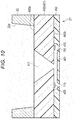
- Fig. 10 is a cross-sectional view taken along a line F10-F10 of Fig. 4 .
- the chemical liquid discharge array 27' is formed by laminating a silicon substrate 400 and a photosensitive resin 450.
- An inlet port 411 connected to the bottom surface opening portion 22a of the liquid outlet port of the chemical liquid holding container 22 is formed on a surface side (also referred to as a second surface 400a) of the silicon substrate 400.
- a thin film heat transfer heater 432 that is an actuator and a wiring that is connected to the thin film heat transfer heater 432 and is not shown in the drawing are formed on a rear surface side (also referred to as a first surface 400b) of the silicon substrate 400.
- the thin film heat transfer heater 432 is electrically connected to the electrode terminal connection portion 26.
- the photosensitive resin 450 is a substrate on which a pressure chamber 410 is formed.
- a flow path 451 connected to the inlet port 411, the pressure chamber 410, and the nozzle 110 are formed on the photosensitive resin 450.
- the pressure chamber 410 is an area where the thin film heat transfer heater 432 is formed in the flow path 451.
- the thin film heat transfer heater 432 generates heat by electric power supplied from a wiring.
- the liquid in the pressure chamber 410 is heated and boiled by the thin film heat transfer heater 432, and thus the liquid is discharged from the nozzle 110.
- a plurality of nozzles 110 is arranged in six rows in the X direction and two rows in the Y direction.
- the plurality of nozzles 110 is positioned inside the bottom surface opening portion 22a of the liquid outlet port of the chemical liquid holding container 22.
- the bottom surface opening portion 22a of the lower portion of the chemical liquid holding container 22 is connected to the inlet port 411 and the flow path 451 of the chemical liquid discharge array 27'.
- the liquid in the chemical liquid holding container 22 is filled from the bottom surface opening portion 22a of the chemical liquid holding container 22 to each pressure chamber 410 in the flow path 451 formed on the photosensitive resin 450 through the inlet port 411 formed on the silicon substrate 400.
- the voltage control signal input to the control signal input terminal 25 of the electrical substrate wiring 24 from the driving circuit 11 is applied to a plurality of thin film heat transfer heater 432 of the chemical liquid discharge array 27'. Therefore, the plurality of thin film heat transfer heater 432 generates heat, and the liquid in the pressure chamber 410 is heated and boiled. As a result, the liquid is discharged from the nozzle 110 as a liquid droplet. A predetermined amount of liquid is dispensed from the nozzle 110 to the well 300 of the microplate 4.
- the liquid is come into contact with the thin film heat transfer heater 432 having a temperature equal to or higher than 300°C. Therefore, in the thermal jet method, it is preferable that the liquid have a high thermal heat resistance (that is, not be a material that is substantially deteriorated by contact with a heater having a temperature equal to or higher than 300°C).
- the discharging system configured as described above acquires the identifier from the liquid discharging device.
- the discharging system acquires the use history of the liquid discharging device indicated by the identifier from the server.
- the discharging system checks the use history when the liquid is to be discharged from the liquid discharging device. When it is determined that the liquid discharging device has been previously used according to the use history, the discharging system will not discharge the liquid from the liquid discharging device.
- the discharging system stores the use history indicating that the liquid discharging device has been used in the server.
- the discharging system can prevent the discharge of a liquid via the reuse of a liquid discharging device that has been previously used.
- the discharging system 500' may have a characteristic of the second embodiment. That is, the processor 15 of the chemical liquid dispensing apparatus 1 of the discharging system 500' transmits the update request rewriting the use history to indicate that the chemical liquid discharging device 2 has been used in the server 50 when the processor 15 detects that the chemical liquid holding container 22 of the chemical liquid discharging device 2 has been filled with the liquid.
- the liquid discharging device configured as described above has a simpler structure as compared to that required for a piezo jet method, and thus it is possible to miniaturize the actuator. Therefore, a liquid discharging device can have nozzles at a higher density that one based on the piezo jet method.
- the driving element 130 has a circular shape.
- the shape of the driving unit is not limited.
- the shape of the driving element 130 may be a diamond shape, an elliptical shape, or the like.
- the shape of the pressure chamber 210 is not limited to a circular shape, and the pressure chamber 210 may be a diamond shape, an elliptical shape, a rectangular shape, or the like.
- the nozzle 110 is disposed at the center of the driving element 130.
- the position of the nozzle 110 is not particular limited.
- the nozzle 110 may be formed on an outer periphery of the driving element 130 rather than within an interior region of the driving element 130.
Landscapes
- Chemical & Material Sciences (AREA)
- Analytical Chemistry (AREA)
- Immunology (AREA)
- Pathology (AREA)
- Health & Medical Sciences (AREA)
- Biochemistry (AREA)
- General Health & Medical Sciences (AREA)
- General Physics & Mathematics (AREA)
- Physics & Mathematics (AREA)
- Life Sciences & Earth Sciences (AREA)
- Engineering & Computer Science (AREA)
- Quality & Reliability (AREA)
- Feeding, Discharge, Calcimining, Fusing, And Gas-Generation Devices (AREA)
- Coating Apparatus (AREA)
- Sampling And Sample Adjustment (AREA)
- Automatic Analysis And Handling Materials Therefor (AREA)
- Infusion, Injection, And Reservoir Apparatuses (AREA)
Abstract
Description
- Embodiments described herein relate generally to a liquid dispensing apparatus and a system.
- In a liquid dispensing apparatus, a liquid is dispensed through a liquid discharging device. The liquid discharging device can be detachable from the liquid dispensing apparatus so that it can be discarded after a single use to prevent contamination.
- However, there is a problem in existing dispensing systems in that the discharging device might be reused or kept in service even though the discharging is designed, or at least intended, only for single use.
- To solve the above-cited problems, there is provided a liquid dispensing apparatus, comprising:
- a base to which a liquid discharging device for discharging a liquid is to be mounted;
- an interface configured to communicate with an external device;
- a driving circuit to supply driving voltages to an actuator of the liquid discharging device; and
- a control unit configured to:
- acquire a use history of the liquid discharging device from the external device through the interface, and
- cause the driving circuit to supply a discharge voltage to the actuator if the acquired use history indicates the liquid discharging device has not been used.
- Preferably the apparatus may further comprise:
- a reader configured to acquire identification information specific to the liquid discharging device, wherein
- the control unit transmits a request to the external device for the use history of the liquid discharging device specified by the identification information.
- Preferably the reader may read a code on the liquid discharging device.
- Preferably the control unit may further be configured to cause the use history stored in the external device to change so as to indicate that the liquid discharging device has been used once the control unit causes the driving circuit to supply the discharge voltage to the liquid discharging device.
- Preferably the control unit may further be configured to cause the use history stored in the external device to change so as to indicate that the liquid discharging device has been used when the control unit detects that a liquid holding container of the liquid discharging device has been filled with the liquid.
- Preferably the actuator may comprise a piezoelectric film.
- Preferably the actuator may be a heater.
- In another exemplary embodiment, there is also provided a liquid discharging system, comprising:
- a liquid dispensing apparatus; and
- an information processing device, wherein
- the liquid dispensing apparatus includes:
- a base to which a liquid discharging device for discharging a liquid is mounted;
- a first interface configured to communicate with the information processing device;
- a driving circuit to supply driving voltages to an actuator of the liquid discharging device; and
- a first control unit configured to:
- acquire a use history from the information processing device through the first interface, and
- cause the driving circuit to supply a discharge voltage to the actuator if the acquired use history indicates the liquid discharging device has not been used, the use history indicating whether or not the liquid discharging device has been previously used, and
- the information processing device includes:
- a storage unit storing the use history;
- a second interface configured to communicate with the liquid dispensing apparatus; and
- a second control unit configured to transmit the use history from the storage unit to the liquid dispensing apparatus through the second interface.
- Preferably the system may further comprise:
- a reader configured to acquire identification information specific to the liquid discharging device, wherein
- the first control unit transmits a request to the information processing device for the use history of the liquid discharging device specified by the identification information.
- Preferably the first control unit may further be configured to cause the use history stored in the information processing device to change so as to indicate that the liquid discharging device has been used once the first control unit causes the driving circuit to supply the discharge voltage to the liquid discharging device.
- Preferably the first control unit may further be configured to cause the use history stored in the information processing device to change so as to indicate that the liquid discharging device has been used when the first control unit detects that a liquid holding container of the liquid discharging device has been filled with the liquid.
- Preferably the actuator may comprise a piezoelectric film.
- Preferably the actuator may be a heater.
- In yet another exemplary embodiment, there is also provided a method for discharging a liquid from a liquid dispensing device, comprising:
- determining a liquid dispensing device is mounted on a liquid dispensing apparatus;
- reading a use history from an external device;
- supplying a first control signal to a driving circuit of the liquid dispensing apparatus to drive an actuator of the liquid dispensing device to discharge a liquid when the use history indicates that the liquid dispensing device has not been previously used; and
- supplying a second control signal to change the use history stored in the external device to indicate that the liquid dispensing device has been previously used.
- Preferably the method may further comprise:
transmitting a signal indicating that the liquid discharging device has been previously used when the use history indicates that the liquid dispensing device has been previously used. - Preferably the driving circuit may supply a discharge voltage to the actuator in response to the first control signal.
- Preferably the second control signal may be supplied when the driving circuit supplies the discharge voltage to the actuator.
- Preferably the second control signal may be supplied when a liquid holding container of the liquid discharging device has been filled with the liquid.
- Preferably the actuator may comprise a piezoelectric film.
- Preferably the actuator may be a heater.
- The above and other objects, features and advantages of the present invention will be made apparent from the following description of the preferred embodiments, given as non-limiting examples, with reference to the accompanying drawings, in which:
-
Fig. 1 is a schematic perspective view of a discharging system according to a first embodiment. -
Fig. 2 is a top view of a liquid discharging device according to the first embodiment. -
Fig. 3 is a bottom view of a liquid discharging device according to the first embodiment. -
Fig. 4 is a cross-sectional view taken along a line F4-F4 ofFig. 2 . -
Fig. 5 is a cross-sectional view taken along a line F5-F5 ofFig. 4 . -
Fig. 6 is a block diagram of a control system of the discharging system according to the first embodiment. -
Fig. 7 is a block diagram of a configuration example of a server according to the first embodiment. -
Fig. 8 is a flowchart showing an operation example of a liquid dispensing apparatus according to the first embodiment. -
Fig. 9 is a flowchart showing an operation example of a liquid dispensing apparatus according to a second embodiment. -
Fig. 10 is a cross-sectional view taken along a line F10-F10 ofFig. 4 according to a third embodiment. - In general, according to one embodiment, a liquid dispensing apparatus includes a base to which a liquid discharging device for discharging a liquid is mounted, an interface configured to communicate with an external device, a driving circuit to supply driving voltages to an actuator of the liquid discharging device, and a control unit configured to acquire a use history of the liquid discharging device from the external device through the interface, and cause the driving circuit to supply a discharge voltage to the actuator if the acquired use history indicates the liquid discharging device has not been used.
- Hereinafter, liquid dispensing apparatuses and liquid discharging systems according to certain example embodiments will be described with reference to the drawings. It should be noted, that the particular embodiments explained below are some possible examples of liquid dispensing apparatuses and chemical liquid discharging systems according to the present disclosure and do not limit the possible configurations, specifications, or the like of liquid dispensing apparatuses and liquid discharging systems according to the present disclosure. The drawings are schematic and are in some instances drawn with exaggeration and omissions for purposes of explanatory convenience. In general, components are not drawn to scale. The number of components, the dimensional ratio between different components, or the like does not necessarily match between different drawings or to actual devices.
- A discharging system according to a first embodiment discharges a predetermined liquid by a piezo jet method. For example, the discharging system discharges several picoliters (pL) to several microliters (µL) of a liquid into a microplate, a multi-well plate, or the like according to a user operation. For example, the discharging system is used in a laboratory in a technical field such as biology, chemistry, or pharmacy research.
- A configuration example of the discharging system according to the first embodiment will be described with reference to
Figs. 1 to 5 .Fig. 1 is a schematic perspective view of the dischargingsystem 500.Fig. 2 is a top view of a chemicalliquid discharging device 2.Fig. 3 is a bottom view of a surface of the chemicalliquid discharging device 2 from which a liquid is discharged.Fig. 4 is a cross-sectional view taken along a line F4-F4 inFig. 2 .Fig. 5 is a cross-sectional view taken along a line F5-F5 inFig. 4 . - As shown in
Fig. 1 , the dischargingsystem 500 includes a chemical liquid dispensing apparatus 1, the chemicalliquid discharging device 2, ahost computer 18, a server 50 (also referred to as an information processing device or external device), and the like. The dischargingsystem 500 may have more elements in addition to the elements depicted inFig. 1 , or some of the elements depicted inFig. 1 may be omitted in some embodiments. - The chemical liquid dispensing apparatus 1 controls the chemical
liquid discharging device 2 to dispense a liquid from the chemicalliquid discharging device 2. - The chemical liquid dispensing apparatus 1 includes a base 3 of a rectangular flat plate shape, and a mounting
module 5 that mounts the chemicalliquid discharging device 2. In the first embodiment, it is assumed that the chemical liquid dispensing apparatus 1 dispenses the liquid into amicroplate 4 having 1536 wells. Here, the front to rear direction of the base 3 is referred to as an X direction, and the right to left direction of the base 3 is referred to as a Y direction. The X direction and the Y direction are orthogonal. - The
microplate 4 is fixed to the base 3. Themicroplate 4 includes a plurality ofwells 300. Each well 300 of themicroplate 4 holds a predetermined volume of a liquid. For example, the liquids in the microplate can be chemicals, reagents, solutions, solvents, or the like and/or may include cells, blood cells, bacteria, plasma, antibodies, DNA, nucleic acids or proteins. - The chemical liquid dispensing apparatus 1 includes a pair of right and left X
direction guide rails microplate 4 on the base 3. Both ends each of the Xdirection guide rails bases 7a and 7b protruding on the base 3. - A Y
direction guide rail 8 extending in the Y direction is installed between the Xdirection guide rails direction guide rail 8 are fixed to an Xdirection moving base 9 that is slidable in the X direction along the Xdirection guide rails - The Y
direction guide rail 8 includes a Ydirection moving base 10 that allows a mountingmodule 5 to move in the Y direction along the Ydirection guide rail 8. The mountingmodule 5 is mounted on the Ydirection moving base 10. The chemicalliquid discharging device 2 is fixed to the mountingmodule 5. - The chemical
liquid discharging device 2 is supported so as to be movable to an arbitrary position in the XY directions orthogonal to each other by a combination of an operation of a movement in the Ydirection moving base 10 along the Ydirection guide rail 8 in the Y direction and an operation of a movement in the Xdirection moving base 9 along the Xdirection guide rails - In the mounting
module 5, aslit 32 for fixing the chemicalliquid discharging device 2 is formed. When the chemicalliquid discharging device 2 is inserted into theslit 32 from a front surface opening portion side of theslit 32, the chemicalliquid discharging device 2 is fixed to the chemical liquid dispensing apparatus 1. - The mounting
module 5 includes a drivingcircuit 11, a reader 40 (also referred to as an acquisition unit) and the like. - The driving
circuit 11 drives the chemicalliquid discharging device 2 based on a signal from theprocessor 15. For example, the drivingcircuit 11 supplies a signal, electric power, and the like to the chemicalliquid discharging device 2 to discharge the liquid from the chemicalliquid discharging device 2. - The
reader 40 is a reading unit that reads acode 29 specific to the chemicalliquid discharging device 2. Thereader 40 captures an image of thecode 29 and decodes thecode 29. Thereader 40 transmits the decoded result to theprocessor 15. - For example, the
reader 40 includes an imaging unit such as a CCD. Thereader 40 may include a light or the like that illuminates thecode 29. - The
reader 40 is installed at a position corresponding to thecode 29 of the chemicalliquid discharging device 2. That is, thereader 40 is installed at a position where thecode 29 may be read when the chemicalliquid discharging device 2 is set in the mountingmodule 5. - The chemical
liquid discharging device 2 discharges the liquid based on a control of the chemical liquid dispensing apparatus 1. - The chemical
liquid discharging device 2 includes abase member 21 of a flat planar shape that is a plate of a rectangular plate shape. As shown inFig. 2 , a plurality of chemicalliquid holding containers 22 is arranged in a row in the Y direction, on a surface side of thebase member 21. In the first embodiment, eight chemicalliquid holding containers 22 are included. However, the number is not limited to eight. As shown inFig. 4 , the chemicalliquid holding container 22 is a container of a cylindrical shape having a bottom, of which a top surface is opened. A chemical liquid holding container recessedportion 21a of a cylindrical shape is formed at a position corresponding to each chemicalliquid holding container 22, on the surface side of thebase member 21. - The bottom portion of the chemical
liquid holding container 22 is adhered and fixed to the recessedportion 21a for the chemical liquid holding container. A bottomsurface opening portion 22a serving as a liquid outlet port is formed at the center position on the bottom portion of the chemicalliquid holding container 22. The opening area of a topsurface opening portion 22b is larger than the opening area of the bottomsurface opening portion 22a of the liquid outlet port. - At both ends of the
base member 21,mount fixing notches 28 for mounting and fixing the mountingmodule 5 are formed respectively. Themount fixing notch 28 is engaged with the mountingmodule 5. Twonotches 28 of thebase member 21 are formed in a notch shape of a semi-long circular shape. Themount fixing notch 28 may be a notch shape of a semi-circular shape, a semi-elliptical shape, a triangular shape, or the like. In the first embodiment, the shapes of the twonotches 28 are different from each other. Therefore, the left and right shapes of thebase member 21 are different, and it is easy to identify the posture of thebase member 21. - In the chemical
liquid discharging device 2, thecode 29 is on thebase member 21. The chemicalliquid discharging device 2 is set in the chemical liquid dispensing apparatus 1 such that thecode 29 on the chemicalliquid discharging device 2 can be readable by thereader 40. - The
code 29 indicates an identifier (that is identification information) for specifying the chemicalliquid discharging device 2. For example, thecode 29 includes a character string, a numerical value, or a combination thereof as the identifier encoded. That is, thecode 29 includes the identifier for specifying the chemicalliquid discharging device 2 when thecode 29 is decoded. Thecode 29 may be a one-dimensional code, a two-dimensional code, or the like. - The
code 29 is attached to the chemicalliquid discharging device 2 in advance at the time of manufacturing the chemicalliquid discharging device 2 or the like. - As shown in
Fig. 3 , the same number ofelectrical substrate 23 as the chemicalliquid holding container 22 are arranged in row in the Y direction, on a rear surface side of thebase member 21. Theelectrical substrate 23 is a flat plate member of a rectangular shape. As shown inFig. 4 , an electrical substrate recessedportion 21b for mounting theelectrical substrate 23 and a chemical liquid dischargearray portion opening 21d connected with the electrical substrate recessedportion 21b are formed, on the rear surface side of thebase member 21. A base end portion of the electrical substrate recessedportion 21b extends to the vicinity of an upper end portion of thebase member 21 inFig. 3 (the position in the vicinity of the right end portion inFig. 4 ). As shown inFig. 4 , a distal end portion of the electrical substrate recessedportion 21b extends to a position overlapping a portion of the chemicalliquid holding container 22. Theelectrical substrate 23 is adhered and fixed to the electrical substrate recessedportion 21b. - An
electrical substrate wiring 24 is patterned and formed on a surface opposite to an adhesive fixing surface of the electrical substrate recessedportion 21b, on theelectrical substrate 23.Wiring patterns driving element 130 are formed on theelectrical substrate wiring 24. - A control
signal input terminal 25 for inputting an electrical signal (also referred to as a driving signal) from the drivingcircuit 11 is formed at one end portion of theelectrical substrate wiring 24. An electrodeterminal connection portion 26 is provided at the other end portion of theelectrical substrate wiring 24. - The
base member 21 is provided with the chemical liquid discharge array portion opening 21d. As shown inFig. 3 , the chemical liquid dischargearray portion opening 21d is an opening portion of a rectangular shape and is formed at a position overlapping with the chemical liquid holding container recessedportion 21a on the rear surface side of thebase member 21. - A chemical
liquid discharge array 27 is adhered and fixed to the bottom surface of the chemicalliquid holding container 22 with the chemicalliquid discharge array 27 covering the bottomsurface opening portion 22a of the chemicalliquid holding container 22. The chemicalliquid discharge array 27 is disposed at a position corresponding to the chemical liquid discharge array portion opening 21d of thebase member 21. - As shown in
Fig. 5 , the chemicalliquid discharge array 27 is formed by laminating anozzle plate 100 and apressure chamber structure 200. Thenozzle plate 100 includes anozzle 110 that discharges the liquid, adiaphragm 120, the drivingelement 130 that is a driving unit, aninsulation film 140 that insulates the drivingelement 130, aprotection film 150 that is protection layer, aliquid repellant film 160. Anactuator 170 includes thediaphragm 120 and the drivingelement 130. For example, a plurality ofnozzles 110 is arranged in 3x3 rows. The plurality ofnozzles 110 is positioned inside the bottomsurface opening portion 22a of the liquid outlet port of the chemicalliquid holding container 22. The chemicalliquid holding container 22, thepressure chamber structure 200, theactuator 170, and the like form a discharging portion that discharges the liquid. - For example, the
diaphragm 120 is integrated with thepressure chamber structure 200. When a heat treatment is performed on asilicon wafer 201 in an oxygen atmosphere, a SiO2 (silicon oxide) film is formed on the surface of thesilicon wafer 201. Thediaphragm 120 uses the SiO2 film on the surface of thesilicon wafer 201. Thediaphragm 120 may be formed by depositing the SiO2 film on the surface of thesilicon wafer 201 by a CVD (Chemical Vapor Deposition) method. - The film thickness of the
diaphragm 120 is preferably in a range of 1 to 30 µm. Thediaphragm 120 may use a semiconductor material such as SiN (silicon nitride), Al2O3 (aluminum oxide), or the like, instead of the SiO2 film. - The driving
element 130 is formed in eachnozzle 110. The drivingelement 130 is an annular shape surrounding thenozzle 110. The shape of the drivingelement 130 is not limited, and may be, for example, a C shape in which a portion of the circular ring is cut out. - The driving
element 130 is electrically connected to the electrodeterminal connection portion 26. The drivingelement 130 is driven by electric power supplied from the electrodeterminal connection portion 26. - The driving
element 130 includes a piezoelectric film that is a piezoelectric material, and uses PZT (Pb(Zr, Ti)O3: lead zirconate titanate). For example, a piezoelectric film included in the drivingelement 130 may use a piezoelectric material such as PTO (PbTiO3: lead titanate), PMNT (Pb(Mg1/3Nb2/3)O3-PbTiO3), PZNT (Pb(Zn1/3Nb2/3)O3-PbTiO3), KNN (a compound of KNbO3 and NaNbO3), ZnO, and A1N may be used. - The piezoelectric film included in the driving
element 130 generates a polarization in the thickness direction. When an electric field in the same direction as the polarization is applied to the drivingelement 130, the drivingelement 130 extends or contracts in a direction orthogonal to the electric field direction. That is, the drivingelement 130 contracts or extends in a direction orthogonal to the film thickness direction. - The
nozzle plate 100 includes theprotection film 150. Theprotection film 150 includes a chemicalliquid passage portion 141 of a cylindrical shape that is connected to thenozzle 110 of thediaphragm 120. - The
nozzle plate 100 includes theliquid repellant film 160 that covers theprotection film 150. For example, theliquid repellant film 160 is formed by spin-coating, for example, a silicon type resin having a characteristic of repelling a liquid. Theliquid repellant film 160 may also be formed by a fluorinated resin material. - The
pressure chamber structure 200 includes awarp reduction film 220 that is a warp reduction layer on a surface opposite to thediaphragm 120. Thepressure chamber structure 200 includes apressure chamber 210 that penetrates thewarp reduction film 220, is positioned at the position of thediaphragm 120, and is connected to thenozzle 110. For example, thepressure chamber 210 is formed in a circular shape positioned in the same axis as thenozzle 110. - The
pressure chamber 210 includes an opening portion connected to the bottomsurface opening portion 22a of the chemicalliquid holding container 22. It is preferable that the size L in the depth direction of the opening portion of thepressure chamber 210 is larger than the size D in the width direction of the opening portion of thepressure chamber 210. The size L in the depth direction is set to be larger than the size D in the width direction. Therefore, the pressure applied to the liquid in thepressure chamber 210 may delay an escape to the chemicalliquid holding container 22 by a vibration of thediaphragm 120 of thenozzle plate 100. - In the
pressure chamber structure 200, the side on which thediaphragm 120 of thepressure chamber 210 is disposed is referred to as afirst surface 200a and the side on which thewarp reduction film 220 is disposed is referred to as asecond surface 200b. The chemicalliquid holding container 22 is adhered to the side of thewarp reduction film 220 of thepressure chamber structure 200 by, for example, an epoxy type adhesive. Thepressure chamber 210 of thepressure chamber structure 200 is connected to the bottomsurface opening portion 22a of the chemicalliquid holding container 22 by an opening portion of the side of thewarp reduction film 220. - The
diaphragm 120 deforms in the thickness direction by an operation of the drivingelement 130 of a surface shape. The chemicalliquid discharging device 2 discharges the liquid supplied to thenozzle 110 by a pressure change generated in thepressure chamber 210 of thepressure chamber structure 200 due to the deformation of thediaphragm 120. - Next, a control system of the discharging
system 500 will be described. - As described above, the discharging
system 500 includes the chemical liquid dispensing apparatus 1, the chemicalliquid discharging device 2, thehost computer 18, theserver 50 and the like. - The
host computer 18 controls the chemical liquid dispensing apparatus 1 according to a user operation. Thehost computer 18 includes anoperation unit 18a, adisplay unit 18b, and the like. Thehost computer 18 is configured with a processor, a RAM, a ROM, a non-volatile memory (NVM), and the like. - The
operation unit 18a receives an operation instruction from the user. For example, theoperation unit 18a is a keyboard, a mouse, a touch panel, or the like. - The
display unit 18b displays various kinds of information by a control of theprocessor 15. For example, thedisplay unit 18b includes a liquid crystal display. When theoperation unit 18a includes a touch panel or the like, thedisplay unit 18b may be integrated with theoperation unit 18a. - The
host computer 18 receives various inputs through theoperation unit 18a. For example, thehost computer 18 receives an input indicating that the chemicalliquid holding container 22 has been filled with a liquid. Thehost computer 18 receives an input selection for discharging the liquid from the chemicalliquid holding container 22. - When the
host computer 18 receives the input selection for discharging the liquid from the chemicalliquid holding container 22, thehost computer 18 transmits a discharge signal for discharging the liquid to the chemical liquid dispensing apparatus 1. - The
host computer 18 may receive inputs for each chemicalliquid holding container 22. For example, thehost computer 18 may receive an input indicating that the chemicalliquid holding container 22 has been filled with a liquid or an input selection for discharging a liquid for each chemicalliquid holding container 22. - As shown in
Fig. 6 , the chemical liquid dispensing apparatus 1 includes the X direction moving base control circuit 9a, the X direction movingbase motor 9b, the Y direction movingbase control circuit 10a, the Y direction movingbase motor 10b, the drivingcircuit 11, theprocessor 15, thememory 16, theinterface 17, thereader 40, areader driving circuit 41, aninterface 42, and the like. Such units are connected to each other through a data bus. The chemical liquid dispensing apparatus 1 may have more elements in addition to the elements depicted inFig. 6 , or some of the elements depicted inFig. 6 may be omitted in some embodiments. - The processor 15 (also referred to as a control unit or a first control unit) has a function of controlling all operations of the chemical liquid dispensing apparatus 1. The
processor 15 may include an internal cache, various interfaces, and the like. Theprocessor 15 realizes various processes by executing a program stored in advance in the internal cache, thememory 16, or the like. - Some of the various functions realized by the execution of the program by the
processor 15 may be realized by a hardware circuit. In this case, theprocessor 15 controls a function executed by the hardware circuit. - The
memory 16 stores various data. For example, thememory 16 stores a control program, a control data, and the like. The control program and the control data are incorporated in advance according to a specification of the chemical liquid dispensing apparatus 1. The control program is a program or the like supporting the function realized by the chemical liquid dispensing apparatus 1. - The
memory 16 temporarily stores data or the like under processing of theprocessor 15. Thememory 16 may store data necessary for executing an application program, an execution result of the application program, and the like. - The
interface 17 is an interface for communicating data to and from thehost computer 18. For example, theinterface 17 is connected to thehost computer 18 through a wired or wireless line. For example, theinterface 17 may support a LAN connection, a USB connection, or a Bluetooth® connection. - The interface 42 (referred to as a first interface) is an interface for communicating data to and from the
server 50. For example, theinterface 42 is connected to theserver 50 through a wired or wireless line. For example, theinterface 42 may support a LAN connection, a USB connection, or a Bluetooth connection. - The
interfaces - The X direction moving base control circuit 9a drives the X direction moving
base motor 9b based on a signal from theprocessor 15. The X direction moving base control circuit 9a drives the X direction movingbase motor 9b by supplying a signal or electric power to the X direction movingbase motor 9b. - The X direction moving
base motor 9b moves the Xdirection moving base 9 in the X direction. For example, the X direction movingbase motor 9b is connected to the Xdirection moving base 9 through a gear or the like and moves the Xdirection moving base 9 in the X direction. - The Y direction moving
base control circuit 10a drives the Y direction movingbase motor 10b based on a signal from theprocessor 15. The Y direction movingbase control circuit 10a drives the Y direction movingbase motor 10b by supplying a signal or electric power to the Y direction movingbase motor 10b. - The Y direction moving
base motor 10b moves the Ydirection moving base 10 in the Y direction. For example, the Y direction movingbase motor 10b is connected to the Ydirection moving base 10 through a gear or the like and moves the Ydirection moving base 10 in the Y direction. - The
reader driving circuit 41 drives thereader 40 according to a signal from theprocessor 15. For example, thereader driving circuit 41 supplies electric power to thereader 40. Thereader driving circuit 41 transmits data output from thereader 40 to theprocessor 15. - The chemical
liquid discharging device 2, the drivingcircuit 11 and thereader 40 are as described above. - Next, the
server 50 will be described. -
Fig. 7 shows a configuration example of theserver 50. - In
Fig. 7 , theserver 50 includes aprocessor 51, aROM 52, aRAM 53, a non-volatile memory (NVM) 54 (referred to as a storage unit), acommunication unit 55, anoperation unit 56, adisplay unit 57, and the like. Such units are connected to each other through a data bus. Theserver 50 may have more elements in addition to the elements depicted inFig. 7 , or some of the elements depicted inFig. 7 may be omitted in some embodiments. - The processor 51 (referred to as a second control unit) has a function of controlling all operations of the
server 50. Theprocessor 51 may include an internal cache, various interfaces, and the like. Theprocessor 51 realizes various processes by executing a program stored in advance in the internal memory, theROM 52, or theNVM 54 in. - Some of the various functions realized by the execution of the program by the
processor 51 may be realized by a hardware circuit. In this case, theprocessor 51 controls a function executed by the hardware circuit. - The
ROM 52 is a nonvolatile memory in which a control program, control data, and the like are stored in advance. The control program and the control data stored in theROM 52 are incorporated in advance according to a specification of theserver 50. For example, theROM 52 stores a program (for example, BIOS) for controlling a circuit board of theserver 50. - The
RAM 53 is a volatile memory. TheRAM 53 temporarily stores data or the like during processing of theprocessor 51. TheRAM 53 stores various application programs based on instructions from theprocessor 51. TheRAM 53 may store data necessary for executing the application program, an execution result of the application program, and the like. - The
NVM 54 is a nonvolatile memory capable of writing and rewriting data. For example, theNVM 54 is configured with a Hard Disk Drive (HDD), a Solid State Drive (SSD), an EEPROM® (registered trademark), a flash memory, or the like. TheNVM 54 stores a control program, an application, various data, and the like according to intended operations of theserver 50. - The
NVM 54 includes astorage area 54a that stores the use history. The use history will be described in detail later. - The communication unit 55 (referred to as a second interface) is an interface for communicating data to and from the chemical liquid dispensing apparatus 1. For example, the
communication unit 55 is connected to the chemical liquid dispensing apparatus 1 through a wired or wireless line. For example, thecommunication unit 55 may support a LAN connection, a USB connection, or a Bluetooth connection. - The
operation unit 56 receives an operation instruction from the user. Theoperation unit 56 transmits a signal indicating the received instruction to theprocessor 51. For example, theoperation unit 56 includes a keyboard, a ten key, and a touch panel. - The
display unit 57 displays various kinds of information by a control of theprocessor 51. For example, thedisplay unit 57 includes a liquid crystal display. When theoperation unit 56 includes a touch panel or the like, thedisplay unit 57 may be integrated with theoperation unit 56. - Next, the use history stored in the
storage area 54a will be described. - The
storage area 54a stores the use history for each chemicalliquid discharging device 2. For example, thestorage area 54a stores an identifier obtained by decoding thecode 29 and a use history specific to the chemical liquid discharging device corresponding to the identifier. - The use history indicates whether or not the corresponding chemical
liquid discharging device 2 has been used. The use history may also indicate whether or not the liquid has been discharged from the chemicalliquid discharging device 2. When the chemicalliquid discharging device 2 has discharged a liquid once from at least one chemicalliquid holding container 22, the use history indicates that the chemicalliquid discharging device 2 has been used. - The use history may be recorded in a bit or the like indicating whether or not the chemical
liquid discharging device 2 has been used. For example, "0" indicates that the chemicalliquid discharging device 2 has not been used (that is unused), "1" indicates that the chemicalliquid discharging device 2 has been used. - The use history may be entered by a user through the
operation unit 56. For example, the user stores the use history of the chemical liquid dispensing apparatus 1 mounted on the chemical liquid dispensing apparatus 1 in thestorage area 54a through theoperation unit 56 or the like. Prior to an initial use of the chemicalliquid discharging device 2, the use history indicates that the corresponding chemicalliquid discharging device 2 has not been used (unused). - Next, a function realized by the
processor 51 of theserver 50 will be described. The following function is realized by theprocessor 51 executing the program stored in theNVM 54 or the like. - First, the
processor 51 has a function of transmitting the use history to the chemical liquid dispensing apparatus 1 through thecommunication unit 55. - The
processor 51 receives an acquisition request to acquire a use history corresponding to a chemicalliquid discharging device 2 through thecommunication unit 55. The acquisition request may include an identifier for specifying the chemicalliquid discharging device 2. When theprocessor 51 receives the acquisition request, theprocessor 51 acquires the use history of the chemicalliquid discharging device 2 from thestorage area 54a. Theprocessor 51 may acquire the use history corresponding to the identifier included in the acquisition request. When theprocessor 51 acquires the use history, theprocessor 51 transmits a response including the use history to the chemical liquid dispensing apparatus 1 through thecommunication unit 55. - The
processor 51 has a function of rewriting the use history according to an update request from the chemical liquid dispensing apparatus 1. - The
processor 51 receives the update request for rewriting the use history to indicate that the chemicalliquid discharging device 2 has been used from the chemical liquid dispensing apparatus 1 through thecommunication unit 55. When theprocessor 51 receives the update request, theprocessor 15 rewrites the use history (e.g., in a bit) indicating that the chemicalliquid discharging device 2 has been used thestorage area 54a. Theprocessor 51 may store the use history indicating that the chemicalliquid discharging device 2 corresponding to the identifier included in the update request has been previously used in thestorage area 54a. - When the
processor 51 rewrites the use history to indicate that the chemicalliquid discharging device 2 has been used in thestorage area 54a, theprocessor 51 transmits a response indicating that the rewriting is successful to the chemical liquid dispensing apparatus 1 through thecommunication unit 55. - When the
processor 51 stores the information indicating that the chemicalliquid discharging device 2 has been used as the use history, theprocessor 51 may lock thestorage area 54a from further rewriting of the corresponding use history. - Next, the function realized by the
processor 15 of the chemical liquid dispensing apparatus 1 will be described. The following function is realized by theprocessor 15 executing the program stored in thememory 16 or the like. - First, the
processor 15 has a function of acquiring the identifier from the chemicalliquid discharging device 2. - The
processor 15 determines whether or not the chemicalliquid discharging device 2 is set in the mountingmodule 5. For example, theprocessor 15 determines whether or not the chemicalliquid discharging device 2 is set in the mountingmodule 5 according to a signal from a sensor (not specifically depicted). - When it is determined that the chemical
liquid discharging device 2 is set in the mountingmodule 5, theprocessor 15 acquires (e.g., causes to read and decode) thecode 29 on the chemicalliquid discharging device 2 through thereader 40. Thereader 40 transmits the decoded code to theprocessor 15. Theprocessor 15 acquires the identifier indicating the chemicalliquid discharging device 2 based on the decoded code transmitted from thereader 40. Theprocessor 15 may decode thecode 29 that is read by thereader 40. - The
processor 15 has a function of acquiring the use history of the chemicalliquid discharging device 2 corresponding to the acquired identifier from theserver 50. - The
processor 15 generates the acquisition request for acquiring the use history of the corresponding chemicalliquid discharging device 2. Theprocessor 15 may store the obtained identifier in the acquisition request. When theprocessor 15 generates the acquisition request, theprocessor 15 transmits the acquisition request to theserver 50 through theinterface 42. - The
processor 15 receives a response including the use history of the chemicalliquid discharging device 2 corresponding to the identifier as a response to the acquisition request from theserver 50. - The
processor 15 has a function of discharging the liquid from the chemicalliquid discharging device 2 based on the acquired use history. - When it is determined that the chemical
liquid discharging device 2 has not been used based on the acquired use history, theprocessor 15 causes a liquid to be discharged from the chemicalliquid discharging device 2. - For example, the user supplies a predetermined amount of the liquid to the chemical
liquid holding container 22 from the topsurface opening portion 22b of the chemicalliquid holding container 22 by a pipette or the like. The liquid is held inside the chemicalliquid holding container 22. The bottomsurface opening portion 22a of the bottom portion of the chemicalliquid holding container 22 is connected to the chemicalliquid discharge array 27. The liquid in the chemicalliquid holding container 22 is filled in eachpressure chamber 210 of the chemicalliquid discharge array 27 through the bottomsurface opening portion 22a of the bottom surface of the chemicalliquid holding container 22. - The liquid in the chemical
liquid discharging device 2 includes any of, for example, a low molecular weight compound, a fluorescent reagent, a protein, an antibody, a nucleic acid, a plasma, a bacteria, a blood cell or a cell. In general, a main solvent in the liquid (substance having the largest weight ratio or volume ratio) is water, glycerin, or dimethylsulfoxide. - The user inputs an operation instruction for discharging the liquid to the
operation unit 18a of thehost computer 18. The user may input the operation instruction for discharging the liquid from a specific chemicalliquid holding container 22. - When the
host computer 18 receives the operation of discharging the liquid, thehost computer 18 transmits a discharge signal instructing the discharge of the liquid with respect to the chemical liquid dispensing apparatus 1. The discharge signal may be an instruction of the discharge of the liquid from a specific chemicalliquid holding container 22. - The
processor 15 receives the discharge signal through theinterface 17. When the acquired use history indicates that the chemicalliquid discharging device 2 has not been used, theprocessor 15 causes the chemicalliquid discharging device 2 to discharge the liquid based on the discharge signal. - The
processor 15 controls the X direction movingbase motor 9b and the Y direction movingbase motor 10b to move the chemicalliquid discharging device 2 set in the mountingmodule 5 to a predetermined position. For example, theprocessor 15 moves the chemicalliquid discharging device 2 to a position where the plurality ofnozzles 110 is inserted into a well 300. Theprocessor 15 may move the chemicalliquid discharging device 2 to the predetermined position according to the discharge signal. - When the chemical
liquid discharging device 2 is moved to the predetermined position, theprocessor 15 applies a voltage for discharging the liquid to the drivingelement 130 using the drivingcircuit 11. - The
processor 15 transmits a signal to the drivingcircuit 11, and a voltage control signal is input from the drivingcircuit 11 to the drivingelement 130. In response to the application of the voltage control signal, the drivingelement 130 deforms thediaphragm 120 to change the volume of thepressure chamber 210. Therefore, the liquid is discharged as a droplet from thenozzle 110 of the chemicalliquid discharge array 27. As a result, the chemicalliquid discharging device 2 dispenses a predetermined amount of liquid from thenozzle 110 to the well 300 of themicroplate 4. - To dispense the predetermined amount of liquid to each well 300 of the
microplate 4, theprocessor 15 repeats an operation instruction for transmitting a signal to the X direction moving base control circuit 9a, the Y direction movingbase control circuit 10a, and the drivingcircuit 11. - The number of times and the position at which the
processor 15 causes the liquid to be discharged are not limited to a specific configuration. - When it is determined that the chemical
liquid discharging device 2 has not been used based on the acquired use history, theprocessor 15 may transmit a signal indicating that the chemicalliquid discharging device 2 has not been used to thehost computer 18. Thehost computer 18 may display that the chemicalliquid discharging device 2 has not been used on thedisplay unit 18b or the like, based on the corresponding signal. - When it is determined that the chemical
liquid discharging device 2 has been used based on the acquired use history, theprocessor 15 does not causes the liquid to be discharged from the chemicalliquid discharging device 2. - When it is determined that the chemical
liquid discharging device 2 has been used based on the acquired use history, theprocessor 15 does not causes the liquid to be discharged even when theprocessor 15 receives the discharge signal. Theprocessor 15 transmits a signal indicating that the chemicalliquid discharging device 2 has been used to thehost computer 18 through theinterface 17. - When the
host computer 18 receives the signal, thehost computer 18 displays a warning or the like indicating that the chemicalliquid discharging device 2 has been used on thedisplay unit 18b or the like. - The
processor 15 has a function of transmitting the update request for storing the information indicating that the chemicalliquid discharging device 2 has been used for rewriting the use history of the corresponding chemicalliquid discharging device 2 in theserver 50 when theprocessor 15 causes the liquid to be discharged. - When the discharge of the liquid has been completed, the
processor 15 generates the update request for rewriting the use history to indicate that the chemicalliquid discharging device 2 has been used. For example, theprocessor 15 stores the acquired identifier in the update request. When theprocessor 15 generates the update request, theprocessor 15 transmits the generated update request to theserver 50 through theinterface 42. - The
processor 15 receives a response indicating that the rewriting has been completed from theserver 50 through theinterface 42. When theprocessor 15 receives a response indicating that the rewriting has been failed or when theprocessor 15 does not receive the response, theprocessor 15 may transmit the generated update request to theserver 50 again. - Next, an operation example of the
processor 15 of the chemical liquid dispensing apparatus 1 will be described. -
Fig. 8 is a flowchart for describing an operation example of theprocessor 15 of the chemical liquid dispensing apparatus 1. - First, the
processor 15 determines whether or not the chemicalliquid discharging device 2 is set in the mounting module 5 (ACT11). When it is determined that the chemicalliquid discharging device 2 is not set in the mounting module 5 (ACT11, NO), theprocessor 15 causes the process to return to ACT11. - When it is determined that the chemical
liquid discharging device 2 is set in the mounting module 5 (ACT11, YES), theprocessor 15 reads the identifier from thecode 29 on the chemical liquid discharging device 2 (ACT12). When theprocessor 15 reads the identifier, theprocessor 15 acquires the use history of the chemicalliquid discharging device 2 corresponding to the identifier from the sever 50 (ACT13). - When the
processor 15 acquires the use history, theprocessor 15 determines whether or not the chemicalliquid discharging device 2 has been used according to the use history (ACT14). - When it is determined that the chemical
liquid discharging device 2 has not been used (is previously unused) according to the use history (ACT14, NO), theprocessor 15 determines whether or not the discharge signal has been received through the interface 17 (ACT15). When it is determined that the discharge signal has not been received through the interface 17 (ACT15, NO), theprocessor 15 causes the process to return to ACT15. - When it is determined that the discharge signal has been received through the interface 17 (ACT15, YES), the
processor 15 causes the chemicalliquid discharging device 2 to discharge the liquid according to the discharge signal (ACT16). - When the chemical
liquid discharging device 2 is caused to discharge the liquid, theprocessor 15 transmits the update request for rewriting the use history to indicate that the chemicalliquid discharging device 2 has been used to the server 50 (ACT 17). - When it is determined that the chemical
liquid discharging device 2 has been used according to the use history (ACT14, YES), theprocessor 15 transmits the signal indicating that the chemicalliquid discharging device 2 has been used to thehost computer 18 through the interface 17 (ACT18). - When the use history indicating that the chemical liquid discharging device has been used is stored in the server 50 (ACT17), or when the signal indicating that the chemical
liquid discharging device 2 has been used is transmitted to the host computer 18 (ACT18), theprocessor 15 ends the operation. - The chemical
liquid discharging device 2 may include an IC module or a Radio Frequency Identifier (RFID) storing the identifier. In this case, the chemical liquid dispensing apparatus 1 includes a reader that read the identifier from the IC module or the RFID. Theprocessor 15 of the chemical liquid dispensing apparatus 1 acquires the identifier from the IC module or the RFID. - The chemical
liquid discharging device 2 may include a character string indicating the identifier. In this case, the chemical liquid dispensing apparatus 1 includes a camera or the like that images the character string. Theprocessor 15 of the chemical liquid dispensing apparatus 1 performs an Optical Character Recognition (OCR) process or the like on a captured including the character string to acquire the identifier. - The chemical
liquid discharging device 2 may indicate the identifier by the shape of thebase member 21 or the like. In this case, theprocessor 15 of the chemical liquid dispensing apparatus 1 may acquire the identifier using a captured image indicating the shape. - The
host computer 18 and theserver 50 may be integrally formed. For example, thehost computer 18 may have a function of theserver 50. - The
storage area 54a of theserver 50 may store the use history of each chemicalliquid holding container 22 of the chemicalliquid discharging device 2. That is, thestorage area 54a stores information indicating whether or not the chemicalliquid holding container 22 has been used. - The
processor 15 acquires the use history of the chemicalliquid holding container 22 specified by the identifier from theserver 50. When theprocessor 15 acquires the use history, theprocessor 15 receives the discharge signal from thehost computer 18. When the discharge signal is received, theprocessor 15 determines whether or not the chemicalliquid holding container 22 has been used according to the use history. When it is determined that the chemicalliquid holding container 22 has not been used (that is unused) by the use history, theprocessor 15 causes the liquid to be discharged from the chemicalliquid holding container 22 according to the discharge signal. When the discharge operation has been completed, theprocessor 15 transmits an update request for rewriting the use history to indicate that the chemicalliquid holding container 22 has been used to theserver 50. - When it is determined that the chemical
liquid holding container 22 has been used according to the use history, theprocessor 15 will not perform the discharge operation even when theprocessor 15 receives the discharge signal. In this case, theprocessor 15 may transmit a signal indicating that the chemicalliquid holding container 22 has been used to thehost computer 18. - The discharging system configured as described above acquires the identifier from the liquid discharging device. The discharging system acquires the use history of the chemical liquid discharging device corresponding to the identifier from the server. The discharging system checks the use history before the liquid is discharged from the liquid discharging device. When it is determined that the liquid discharging device has been used by the use history, the discharging system will not cause the liquid discharging device to discharge the liquid.
- Once the liquid discharging device has discharged the liquid, the discharging system updates the use history indicating that the liquid discharging device has been used in the server.
- As a result, the discharging system can prevent the discharge of a liquid via the reuse of a liquid discharging device that has been previously used.
- A chemical liquid dispensing apparatus 1 according to a second embodiment is different from that of the first embodiment in that the chemical liquid dispensing apparatus 1 according to the second embodiment transmits an update request for updating the use history to indicate that the chemical
liquid discharging device 2 has been used once the chemicalliquid holding container 22 has been filled with the liquid. Therefore, the same reference numerals are used for the components that are substantially the same as those of the first embodiment, and the description of repeated components may be omitted. - The
host computer 18 receives an input indicating that the chemicalliquid holding container 22 has been filled with the liquid through theoperation unit 18a. For example, when the chemicalliquid holding container 22 has been filled with the liquid, the user enters an input that indicates filling has been completed to theoperation unit 18a. - When the
host computer 18 receives an input indicating the chemicalliquid holding container 22 has been filled with the liquid, thehost computer 18 transmits a filling signal indicating that the chemicalliquid holding container 22 has been filled with the liquid to the chemical liquid dispensing apparatus 1 through theinterface 17. - Next, the function realized by the
processor 15 of the chemical liquid dispensing apparatus 1 will be described. The following function is realized by theprocessor 15 executing the program stored in thememory 16 or the like. - The
processor 15 has a function of detecting that the chemicalliquid holding container 22 is filled with the liquid. - For example, the
processor 15 determines whether or not the filling signal has been received from thehost computer 18. When it is determined that the filling signal has been received from thehost computer 18, theprocessor 15 determines that the chemicalliquid holding container 22 has been filled with the liquid. - The chemical liquid dispensing apparatus 1 or the chemical
liquid discharging device 2 may include a sensor for detecting a filling of the chemicalliquid holding container 22 with the liquid. Theprocessor 15 may detect a filling of the chemicalliquid holding container 22 using the corresponding sensor. - A method of detecting a filling of the chemical
liquid holding container 22 by theprocessor 15 is not limited to any specific method. - The
processor 15 has a function of transmitting the update request for rewriting the use history of the chemicalliquid discharging device 2 when theprocessor 15 detects that the chemicalliquid holding container 22 has been filled with the liquid. - The operation of transmitting the update request for rewriting the use history of the chemical
liquid discharging device 2 in theserver 50 by theprocessor 15 is the same as that of the first embodiment, and thus detailed descriptions thereof are omitted. - Next, an operation example of the
processor 15 of the chemical liquid dispensing apparatus 1 will be described. -
Fig. 9 is a flowchart for describing an operation example of theprocessor 15 of the chemical liquid dispensing apparatus 1. - First, the
processor 15 determines whether or not the chemicalliquid discharging device 2 is set in the mounting module 5 (ACT21). When it is determined that the chemicalliquid discharging device 2 is not set in the mounting module 5 (ACT21, NO), theprocessor 15 causes the process to return to ACT21. - When it is determined that the chemical
liquid discharging device 2 is set in the mounting module 5 (ACT21, YES), theprocessor 15 reads the identifier from thecode 29 of the chemical liquid discharging device 2 (ACT22). When theprocessor 15 reads the identifier, theprocessor 15 acquires the use history of the chemicalliquid discharging device 2 specified by the identifier from the server 50 (ACT23). - When the
processor 15 acquires the use history, theprocessor 15 determines whether or not the chemicalliquid discharging device 2 specified by the identified has been used according to the use history (ACT24). - When it is determined that the chemical
liquid discharging device 2 has not been used (is previously unused) according to the use history (ACT24, NO), theprocessor 15 determines whether or not the filling signal has been received through the interface 17 (ACT25). When it is determined that the filling signal has not been received through the interface 17 (ACT25, NO), theprocessor 15 returns to ACT25. - When it is determined that the filling signal has been received through the interface 17 (ACT25, YES), the
processor 15 transmits the update request for rewriting the use history to indicate that the chemicalliquid discharging device 2 has been used (ACT26). - When the update request for rewriting the use history to indicate that the chemical
liquid discharging device 2 has been used is transmitted, theprocessor 15 determines whether or not the discharge signal has been received through the interface 17 (ACT27). When it is determined that the discharge signal has not been received through the interface 17 (ACT27, NO), theprocessor 15 causes the process to return to ACT27. - When it is determined that the discharge signal has been received through the interface 17 (ACT27, YES), the
processor 15 causes the chemicalliquid discharging device 2 to discharge the liquid according to the discharge signal (ACT28). - When it is determined that the chemical
liquid discharging device 2 has been previously used according to the use history (ACT24, YES), theprocessor 15 transmits the signal indicating that the chemicalliquid discharging device 2 has been used to thehost computer 18 through the interface 17 (ACT29). - When the chemical
liquid discharging device 2 is caused to discharge the liquid (ACT28), or when the signal indicating that the chemicalliquid discharging device 2 has been previously used is transmitted to the host computer 18 (ACT29), theprocessor 15 ends the operation. - Similarly to the first embodiment, the
storage area 54a of theserver 50 may store the use history of each chemicalliquid holding container 22 of the chemicalliquid discharging device 2. That is, thestorage area 54a stores information indicating whether or not the chemicalliquid holding container 22 has been previously used for each chemicalliquid holding container 22 of the chemicalliquid discharging device 2. - For example, the
processor 15 acquires the use history of each chemicalliquid holding container 22 of the chemicalliquid discharging device 2 specified by the identifier from theserver 50. When theprocessor 15 acquires the use history, theprocessor 15 receives the filling signal from thehost computer 18. When theprocessor 15 receives the filling signal, theprocessor 15 determines whether or not the corresponding chemicalliquid holding container 22 has been used according to the use history corresponding to the chemicalliquid holding container 22 indicated filled by the filling signal. When it is determined that the chemicalliquid holding container 22 has not been used (unused) according to the use history, theprocessor 15 transmits an update request for rewriting the use history to indicate the chemicalliquid holding container 22 has been used to theserver 50. - When it is determined that the chemical
liquid holding container 22 has been used according to the use history, theprocessor 15 will not perform the discharge operation even when theprocessor 15 receives the discharge signal. In this case, theprocessor 15 may transmit a signal indicating that the chemicalliquid holding container 22 has been previously used to thehost computer 18. - The discharging system configured as described above transmits the update request for rewriting the use history of the liquid discharging device to indicate that the liquid discharging device has been used to the server once the liquid holding container has been filled with the liquid. As a result, the discharging system can store the information indicating that the liquid discharging device has been used in the server even when the discharge operation of the liquid from the liquid holding container filled with the liquid will not be performed.
- Therefore, the discharging system can prevent contamination even when the discharge operation of the liquid from the liquid holding container filled with the liquid is not performed.
- A liquid discharging device according to a third embodiment is different from that of the first embodiment in that the liquid discharging device according to the third embodiment discharges the liquid by a thermal jet method. Therefore, the same reference numerals are used for the components that are substantially the same as those of the first embodiment, and the description of repeated components may be omitted.
- The discharging system 500' according to the third embodiment includes a chemical liquid discharging device 2'.
- The chemical liquid discharging device 2' includes a chemical liquid discharge array 27' in place of the chemical
liquid discharge array 27. -
Fig. 10 is a cross-sectional view taken along a line F10-F10 ofFig. 4 . - As shown in
Fig. 10 , the chemical liquid discharge array 27' is formed by laminating asilicon substrate 400 and aphotosensitive resin 450. Aninlet port 411 connected to the bottomsurface opening portion 22a of the liquid outlet port of the chemicalliquid holding container 22 is formed on a surface side (also referred to as asecond surface 400a) of thesilicon substrate 400. A thin filmheat transfer heater 432 that is an actuator and a wiring that is connected to the thin filmheat transfer heater 432 and is not shown in the drawing are formed on a rear surface side (also referred to as afirst surface 400b) of thesilicon substrate 400. The thin filmheat transfer heater 432 is electrically connected to the electrodeterminal connection portion 26. - The
photosensitive resin 450 is a substrate on which apressure chamber 410 is formed. Aflow path 451 connected to theinlet port 411, thepressure chamber 410, and thenozzle 110 are formed on thephotosensitive resin 450. Thepressure chamber 410 is an area where the thin filmheat transfer heater 432 is formed in theflow path 451. The thin filmheat transfer heater 432 generates heat by electric power supplied from a wiring. The liquid in thepressure chamber 410 is heated and boiled by the thin filmheat transfer heater 432, and thus the liquid is discharged from thenozzle 110. - For example, a plurality of
nozzles 110 is arranged in six rows in the X direction and two rows in the Y direction. The plurality ofnozzles 110 is positioned inside the bottomsurface opening portion 22a of the liquid outlet port of the chemicalliquid holding container 22. - Next, an operation of discharging the liquid will be described. The bottom
surface opening portion 22a of the lower portion of the chemicalliquid holding container 22 is connected to theinlet port 411 and theflow path 451 of the chemical liquid discharge array 27'. The liquid in the chemicalliquid holding container 22 is filled from the bottomsurface opening portion 22a of the chemicalliquid holding container 22 to eachpressure chamber 410 in theflow path 451 formed on thephotosensitive resin 450 through theinlet port 411 formed on thesilicon substrate 400. - In this state, the voltage control signal input to the control
signal input terminal 25 of theelectrical substrate wiring 24 from the drivingcircuit 11 is applied to a plurality of thin filmheat transfer heater 432 of the chemical liquid discharge array 27'. Therefore, the plurality of thin filmheat transfer heater 432 generates heat, and the liquid in thepressure chamber 410 is heated and boiled. As a result, the liquid is discharged from thenozzle 110 as a liquid droplet. A predetermined amount of liquid is dispensed from thenozzle 110 to the well 300 of themicroplate 4. - In the thermal jet method, the liquid is come into contact with the thin film
heat transfer heater 432 having a temperature equal to or higher than 300°C. Therefore, in the thermal jet method, it is preferable that the liquid have a high thermal heat resistance (that is, not be a material that is substantially deteriorated by contact with a heater having a temperature equal to or higher than 300°C). - The discharging system configured as described above acquires the identifier from the liquid discharging device. The discharging system acquires the use history of the liquid discharging device indicated by the identifier from the server. The discharging system checks the use history when the liquid is to be discharged from the liquid discharging device. When it is determined that the liquid discharging device has been previously used according to the use history, the discharging system will not discharge the liquid from the liquid discharging device.
- When the liquid discharging device discharges the liquid, the discharging system stores the use history indicating that the liquid discharging device has been used in the server.
- As a result, the discharging system can prevent the discharge of a liquid via the reuse of a liquid discharging device that has been previously used.
- The discharging system 500' may have a characteristic of the second embodiment. That is, the
processor 15 of the chemical liquid dispensing apparatus 1 of the discharging system 500' transmits the update request rewriting the use history to indicate that the chemicalliquid discharging device 2 has been used in theserver 50 when theprocessor 15 detects that the chemicalliquid holding container 22 of the chemicalliquid discharging device 2 has been filled with the liquid. - The liquid discharging device configured as described above has a simpler structure as compared to that required for a piezo jet method, and thus it is possible to miniaturize the actuator. Therefore, a liquid discharging device can have nozzles at a higher density that one based on the piezo jet method.
- In the example embodiments described above, the driving
element 130 has a circular shape. However, the shape of the driving unit is not limited. For example, the shape of the drivingelement 130 may be a diamond shape, an elliptical shape, or the like. The shape of thepressure chamber 210 is not limited to a circular shape, and thepressure chamber 210 may be a diamond shape, an elliptical shape, a rectangular shape, or the like. - In the example embodiments described above, the
nozzle 110 is disposed at the center of the drivingelement 130. However, as long as the liquid of thepressure chamber 210 can be discharged, the position of thenozzle 110 is not particular limited. For example, thenozzle 110 may be formed on an outer periphery of the drivingelement 130 rather than within an interior region of the drivingelement 130. - While certain embodiments have been described, these embodiments have been presented by way of example only, and are not intended to limit the scope of the inventions. Indeed, the novel embodiments described herein may be embodied in a variety of other forms. Furthermore, various omissions, substitutions and changes in the form of the embodiments described herein may be made without departing from the scope of the inventions. The accompanying claims and their equivalents are intended to cover such forms or modifications as would fall within the scope of the inventions.
Claims (15)
- A liquid dispensing apparatus, comprising:a base to which a liquid discharging device for discharging a liquid is to be mounted;an interface configured to communicate with an external device;a driving circuit to supply driving voltages to an actuator of the liquid discharging device; anda control unit configured to:acquire a use history of the liquid discharging device from the external device through the interface, andcause the driving circuit to supply a discharge voltage to the actuator if the acquired use history indicates the liquid discharging device has not been used.
- The apparatus according to claim 1, further comprising:a reader configured to acquire identification information specific to the liquid discharging device, whereinthe control unit transmits a request to the external device for the use history of the liquid discharging device specified by the identification information.
- The apparatus according to claim 2, wherein the reader reads a code on the liquid discharging device.
- The apparatus according to any one of claims 1 to 3, wherein the control unit is further configured to cause the use history stored in the external device to change so as to indicate that the liquid discharging device has been used once the control unit causes the driving circuit to supply the discharge voltage to the liquid discharging device.
- The apparatus according to any one of claims 1 to 3, wherein the control unit is further configured to cause the use history stored in the external device to change so as to indicate that the liquid discharging device has been used when the control unit detects that a liquid holding container of the liquid discharging device has been filled with the liquid.
- The apparatus according to any one of claims 1 to 5, wherein the actuator comprises a piezoelectric film.
- The apparatus according to any one of claims 1 to 6, wherein the actuator is a heater.
- A liquid discharging system, comprising:a liquid dispensing apparatus; andan information processing device, whereinthe liquid dispensing apparatus includes:a base to which a liquid discharging device for discharging a liquid is mounted;a first interface configured to communicate with the information processing device;a driving circuit to supply driving voltages to an actuator of the liquid discharging device; anda first control unit configured to:acquire a use history from the information processing device through the first interface, andcause the driving circuit to supply a discharge voltage to the actuator if the acquired use history indicates the liquid discharging device has not been used, the use history indicating whether or not the liquid discharging device has been previously used, andthe information processing device includes:a storage unit storing the use history;a second interface configured to communicate with the liquid dispensing apparatus; anda second control unit configured to transmit the use history from the storage unit to the liquid dispensing apparatus through the second interface.
- The system according to claim 8, further comprising:a reader configured to acquire identification information specific to the liquid discharging device, whereinthe first control unit transmits a request to the information processing device for the use history of the liquid discharging device specified by the identification information.
- The system according to claim 8 or 9, wherein the first control unit is further configured to cause the use history stored in the information processing device to change so as to indicate that the liquid discharging device has been used once the first control unit causes the driving circuit to supply the discharge voltage to the liquid discharging device.
- The system according to claim 8 or 9, wherein the first control unit is further configured to cause the use history stored in the information processing device to change so as to indicate that the liquid discharging device has been used when the first control unit detects that a liquid holding container of the liquid discharging device has been filled with the liquid.
- A method for discharging a liquid from a liquid dispensing device, comprising:determining a liquid dispensing device is mounted on a liquid dispensing apparatus;reading a use history from an external device;supplying a first control signal to a driving circuit of the liquid dispensing apparatus to drive an actuator of the liquid dispensing device to discharge a liquid when the use history indicates that the liquid dispensing device has not been previously used; andsupplying a second control signal to change the use history stored in the external device to indicate that the liquid dispensing device has been previously used.
- The method according to claim 12, further comprising:transmitting a signal indicating that the liquid discharging device has been previously used when the use history indicates that the liquid dispensing device has been previously used.
- The method according to claim 12 or 13, wherein the driving circuit supplies a discharge voltage to the actuator in response to the first control signal, and the second control signal is supplied when the driving circuit supplies the discharge voltage to the actuator.
- The method according to claim 12 or 13, wherein the second control signal is supplied when a liquid holding container of the liquid discharging device has been filled with the liquid.
Applications Claiming Priority (1)
| Application Number | Priority Date | Filing Date | Title |
|---|---|---|---|
| JP2017159477A JP7019343B2 (en) | 2017-08-22 | 2017-08-22 | Drug drop device and system |
Publications (2)
| Publication Number | Publication Date |
|---|---|
| EP3447498A1 true EP3447498A1 (en) | 2019-02-27 |
| EP3447498B1 EP3447498B1 (en) | 2024-10-30 |
Family
ID=63311843
Family Applications (1)
| Application Number | Title | Priority Date | Filing Date |
|---|---|---|---|
| EP18189604.4A Active EP3447498B1 (en) | 2017-08-22 | 2018-08-17 | Liquid dispensing apparatus and system |
Country Status (4)
| Country | Link |
|---|---|
| US (1) | US20190060933A1 (en) |
| EP (1) | EP3447498B1 (en) |
| JP (1) | JP7019343B2 (en) |
| CN (1) | CN109425747A (en) |
Families Citing this family (5)
| Publication number | Priority date | Publication date | Assignee | Title |
|---|---|---|---|---|
| JP6925909B2 (en) | 2017-08-22 | 2021-08-25 | 東芝テック株式会社 | Drug droplet drop device and drug solution discharge device |
| JP2019184495A (en) | 2018-04-13 | 2019-10-24 | 東芝テック株式会社 | Droplet dispensing device |
| CN113710376A (en) * | 2019-04-26 | 2021-11-26 | 株式会社资生堂 | Liquid discharge device and liquid discharge system |
| JP7458894B2 (en) | 2020-05-15 | 2024-04-01 | 東芝テック株式会社 | Droplet dispensing device |
| CN113588971B (en) * | 2021-06-18 | 2023-09-15 | 深圳迈瑞动物医疗科技股份有限公司 | Sample analyzer and reagent management method |
Citations (3)
| Publication number | Priority date | Publication date | Assignee | Title |
|---|---|---|---|---|
| US20060190185A1 (en) * | 1997-08-11 | 2006-08-24 | Ventana Medical Systems, Inc. | Memory management method and apparatus for automated biological reaction system |
| US20090049933A1 (en) * | 2005-07-01 | 2009-02-26 | Biomerieux | Automatic pipetting device for ensuring the traceability of a performed analysis |
| US20170165969A1 (en) * | 2015-06-29 | 2017-06-15 | Toshiba Tec Kabushiki Kaisha | Liquid-tolerant liquid droplet ejecting apparatus |
Family Cites Families (4)
| Publication number | Priority date | Publication date | Assignee | Title |
|---|---|---|---|---|
| CN1826218B (en) * | 2003-07-18 | 2010-09-22 | Dade白令公司 | Automated Multi-Detector Analyzer |
| JP2007285920A (en) * | 2006-04-18 | 2007-11-01 | Olympus Corp | Analyzer |
| JP5898972B2 (en) * | 2012-01-23 | 2016-04-06 | 株式会社日立ハイテクノロジーズ | Automatic analyzer |
| CN107250806B (en) * | 2015-03-02 | 2019-09-17 | 株式会社日立高新技术 | Automatic analysing apparatus |
-
2017
- 2017-08-22 JP JP2017159477A patent/JP7019343B2/en active Active
-
2018
- 2018-07-09 CN CN201810746185.9A patent/CN109425747A/en not_active Withdrawn
- 2018-08-17 EP EP18189604.4A patent/EP3447498B1/en active Active
- 2018-08-20 US US16/104,976 patent/US20190060933A1/en not_active Abandoned
Patent Citations (3)
| Publication number | Priority date | Publication date | Assignee | Title |
|---|---|---|---|---|
| US20060190185A1 (en) * | 1997-08-11 | 2006-08-24 | Ventana Medical Systems, Inc. | Memory management method and apparatus for automated biological reaction system |
| US20090049933A1 (en) * | 2005-07-01 | 2009-02-26 | Biomerieux | Automatic pipetting device for ensuring the traceability of a performed analysis |
| US20170165969A1 (en) * | 2015-06-29 | 2017-06-15 | Toshiba Tec Kabushiki Kaisha | Liquid-tolerant liquid droplet ejecting apparatus |
Also Published As
| Publication number | Publication date |
|---|---|
| CN109425747A (en) | 2019-03-05 |
| JP2019037909A (en) | 2019-03-14 |
| US20190060933A1 (en) | 2019-02-28 |
| JP7019343B2 (en) | 2022-02-15 |
| EP3447498B1 (en) | 2024-10-30 |
Similar Documents
| Publication | Publication Date | Title |
|---|---|---|
| EP3447498B1 (en) | Liquid dispensing apparatus and system | |
| US11511300B2 (en) | Chemical liquid dispensing apparatus and chemical liquid discharging device | |
| US20200298558A1 (en) | Liquid dispensing apparatus and liquid discharging device | |
| EP3447454A1 (en) | Liquid dispensing apparatus | |
| EP3446783A1 (en) | Liquid discharging device and liquid dispensing apparatus | |
| EP3552705A1 (en) | Droplet dispensing apparatus | |
| EP3446876B1 (en) | Liquid dispensing apparatus and corresponding method | |
| US11247467B2 (en) | Chemical liquid dispensing apparatus | |
| EP3608023A1 (en) | Chemical solution discharge device | |
| JP2024116586A (en) | LIQUID EJECTION HEAD AND LIQUID EJECTION APPARATUS |
Legal Events
| Date | Code | Title | Description |
|---|---|---|---|
| PUAI | Public reference made under article 153(3) epc to a published international application that has entered the european phase |
Free format text: ORIGINAL CODE: 0009012 |
|
| STAA | Information on the status of an ep patent application or granted ep patent |
Free format text: STATUS: THE APPLICATION HAS BEEN PUBLISHED |
|
| AK | Designated contracting states |
Kind code of ref document: A1 Designated state(s): AL AT BE BG CH CY CZ DE DK EE ES FI FR GB GR HR HU IE IS IT LI LT LU LV MC MK MT NL NO PL PT RO RS SE SI SK SM TR |
|
| AX | Request for extension of the european patent |
Extension state: BA ME |
|
| STAA | Information on the status of an ep patent application or granted ep patent |
Free format text: STATUS: REQUEST FOR EXAMINATION WAS MADE |
|
| 17P | Request for examination filed |
Effective date: 20190827 |
|
| RBV | Designated contracting states (corrected) |
Designated state(s): AL AT BE BG CH CY CZ DE DK EE ES FI FR GB GR HR HU IE IS IT LI LT LU LV MC MK MT NL NO PL PT RO RS SE SI SK SM TR |
|
| STAA | Information on the status of an ep patent application or granted ep patent |
Free format text: STATUS: EXAMINATION IS IN PROGRESS |
|
| 17Q | First examination report despatched |
Effective date: 20220105 |
|
| GRAP | Despatch of communication of intention to grant a patent |
Free format text: ORIGINAL CODE: EPIDOSNIGR1 |
|
| STAA | Information on the status of an ep patent application or granted ep patent |
Free format text: STATUS: GRANT OF PATENT IS INTENDED |
|
| INTG | Intention to grant announced |
Effective date: 20240529 |
|
| GRAS | Grant fee paid |
Free format text: ORIGINAL CODE: EPIDOSNIGR3 |
|
| GRAA | (expected) grant |
Free format text: ORIGINAL CODE: 0009210 |
|
| STAA | Information on the status of an ep patent application or granted ep patent |
Free format text: STATUS: THE PATENT HAS BEEN GRANTED |
|
| RAP1 | Party data changed (applicant data changed or rights of an application transferred) |
Owner name: RISO TECHNOLOGIES CORPORATION |
|
| AK | Designated contracting states |
Kind code of ref document: B1 Designated state(s): AL AT BE BG CH CY CZ DE DK EE ES FI FR GB GR HR HU IE IS IT LI LT LU LV MC MK MT NL NO PL PT RO RS SE SI SK SM TR |
|
| REG | Reference to a national code |
Ref country code: GB Ref legal event code: FG4D |
|
| REG | Reference to a national code |
Ref country code: CH Ref legal event code: EP |
|
| REG | Reference to a national code |
Ref country code: IE Ref legal event code: FG4D |
|
| REG | Reference to a national code |
Ref country code: DE Ref legal event code: R096 Ref document number: 602018075910 Country of ref document: DE |
|
| P01 | Opt-out of the competence of the unified patent court (upc) registered |
Free format text: CASE NUMBER: APP_68099/2024 Effective date: 20241226 |
|
| P02 | Opt-out of the competence of the unified patent court (upc) changed |
Free format text: CASE NUMBER: APP_68412/2024 Effective date: 20241227 |
|
| REG | Reference to a national code |
Ref country code: LT Ref legal event code: MG9D |
|
| REG | Reference to a national code |
Ref country code: NL Ref legal event code: MP Effective date: 20241030 |
|
| PG25 | Lapsed in a contracting state [announced via postgrant information from national office to epo] |
Ref country code: IS Free format text: LAPSE BECAUSE OF FAILURE TO SUBMIT A TRANSLATION OF THE DESCRIPTION OR TO PAY THE FEE WITHIN THE PRESCRIBED TIME-LIMIT Effective date: 20250228 Ref country code: HR Free format text: LAPSE BECAUSE OF FAILURE TO SUBMIT A TRANSLATION OF THE DESCRIPTION OR TO PAY THE FEE WITHIN THE PRESCRIBED TIME-LIMIT Effective date: 20241030 Ref country code: PT Free format text: LAPSE BECAUSE OF FAILURE TO SUBMIT A TRANSLATION OF THE DESCRIPTION OR TO PAY THE FEE WITHIN THE PRESCRIBED TIME-LIMIT Effective date: 20250228 |
|
| PG25 | Lapsed in a contracting state [announced via postgrant information from national office to epo] |
Ref country code: FI Free format text: LAPSE BECAUSE OF FAILURE TO SUBMIT A TRANSLATION OF THE DESCRIPTION OR TO PAY THE FEE WITHIN THE PRESCRIBED TIME-LIMIT Effective date: 20241030 Ref country code: NL Free format text: LAPSE BECAUSE OF FAILURE TO SUBMIT A TRANSLATION OF THE DESCRIPTION OR TO PAY THE FEE WITHIN THE PRESCRIBED TIME-LIMIT Effective date: 20241030 |
|
| REG | Reference to a national code |
Ref country code: AT Ref legal event code: MK05 Ref document number: 1737358 Country of ref document: AT Kind code of ref document: T Effective date: 20241030 |
|
| PG25 | Lapsed in a contracting state [announced via postgrant information from national office to epo] |
Ref country code: BG Free format text: LAPSE BECAUSE OF FAILURE TO SUBMIT A TRANSLATION OF THE DESCRIPTION OR TO PAY THE FEE WITHIN THE PRESCRIBED TIME-LIMIT Effective date: 20241030 |
|
| PG25 | Lapsed in a contracting state [announced via postgrant information from national office to epo] |
Ref country code: ES Free format text: LAPSE BECAUSE OF FAILURE TO SUBMIT A TRANSLATION OF THE DESCRIPTION OR TO PAY THE FEE WITHIN THE PRESCRIBED TIME-LIMIT Effective date: 20241030 |
|
| PG25 | Lapsed in a contracting state [announced via postgrant information from national office to epo] |
Ref country code: NO Free format text: LAPSE BECAUSE OF FAILURE TO SUBMIT A TRANSLATION OF THE DESCRIPTION OR TO PAY THE FEE WITHIN THE PRESCRIBED TIME-LIMIT Effective date: 20250130 |
|
| PG25 | Lapsed in a contracting state [announced via postgrant information from national office to epo] |
Ref country code: LV Free format text: LAPSE BECAUSE OF FAILURE TO SUBMIT A TRANSLATION OF THE DESCRIPTION OR TO PAY THE FEE WITHIN THE PRESCRIBED TIME-LIMIT Effective date: 20241030 Ref country code: GR Free format text: LAPSE BECAUSE OF FAILURE TO SUBMIT A TRANSLATION OF THE DESCRIPTION OR TO PAY THE FEE WITHIN THE PRESCRIBED TIME-LIMIT Effective date: 20250131 Ref country code: AT Free format text: LAPSE BECAUSE OF FAILURE TO SUBMIT A TRANSLATION OF THE DESCRIPTION OR TO PAY THE FEE WITHIN THE PRESCRIBED TIME-LIMIT Effective date: 20241030 |
|
| PG25 | Lapsed in a contracting state [announced via postgrant information from national office to epo] |
Ref country code: PL Free format text: LAPSE BECAUSE OF FAILURE TO SUBMIT A TRANSLATION OF THE DESCRIPTION OR TO PAY THE FEE WITHIN THE PRESCRIBED TIME-LIMIT Effective date: 20241030 |
|
| PG25 | Lapsed in a contracting state [announced via postgrant information from national office to epo] |
Ref country code: RS Free format text: LAPSE BECAUSE OF FAILURE TO SUBMIT A TRANSLATION OF THE DESCRIPTION OR TO PAY THE FEE WITHIN THE PRESCRIBED TIME-LIMIT Effective date: 20250130 |
|
| PG25 | Lapsed in a contracting state [announced via postgrant information from national office to epo] |
Ref country code: SM Free format text: LAPSE BECAUSE OF FAILURE TO SUBMIT A TRANSLATION OF THE DESCRIPTION OR TO PAY THE FEE WITHIN THE PRESCRIBED TIME-LIMIT Effective date: 20241030 |
|
| PG25 | Lapsed in a contracting state [announced via postgrant information from national office to epo] |
Ref country code: DK Free format text: LAPSE BECAUSE OF FAILURE TO SUBMIT A TRANSLATION OF THE DESCRIPTION OR TO PAY THE FEE WITHIN THE PRESCRIBED TIME-LIMIT Effective date: 20241030 |
|
| PG25 | Lapsed in a contracting state [announced via postgrant information from national office to epo] |
Ref country code: EE Free format text: LAPSE BECAUSE OF FAILURE TO SUBMIT A TRANSLATION OF THE DESCRIPTION OR TO PAY THE FEE WITHIN THE PRESCRIBED TIME-LIMIT Effective date: 20241030 |
|
| PG25 | Lapsed in a contracting state [announced via postgrant information from national office to epo] |
Ref country code: RO Free format text: LAPSE BECAUSE OF FAILURE TO SUBMIT A TRANSLATION OF THE DESCRIPTION OR TO PAY THE FEE WITHIN THE PRESCRIBED TIME-LIMIT Effective date: 20241030 |
|
| PG25 | Lapsed in a contracting state [announced via postgrant information from national office to epo] |
Ref country code: SK Free format text: LAPSE BECAUSE OF FAILURE TO SUBMIT A TRANSLATION OF THE DESCRIPTION OR TO PAY THE FEE WITHIN THE PRESCRIBED TIME-LIMIT Effective date: 20241030 |
|
| PG25 | Lapsed in a contracting state [announced via postgrant information from national office to epo] |
Ref country code: CZ Free format text: LAPSE BECAUSE OF FAILURE TO SUBMIT A TRANSLATION OF THE DESCRIPTION OR TO PAY THE FEE WITHIN THE PRESCRIBED TIME-LIMIT Effective date: 20241030 |
|
| PG25 | Lapsed in a contracting state [announced via postgrant information from national office to epo] |
Ref country code: IT Free format text: LAPSE BECAUSE OF FAILURE TO SUBMIT A TRANSLATION OF THE DESCRIPTION OR TO PAY THE FEE WITHIN THE PRESCRIBED TIME-LIMIT Effective date: 20241030 |
|
| REG | Reference to a national code |
Ref country code: DE Ref legal event code: R097 Ref document number: 602018075910 Country of ref document: DE |
|
| PLBE | No opposition filed within time limit |
Free format text: ORIGINAL CODE: 0009261 |
|
| STAA | Information on the status of an ep patent application or granted ep patent |
Free format text: STATUS: NO OPPOSITION FILED WITHIN TIME LIMIT |
|
| PG25 | Lapsed in a contracting state [announced via postgrant information from national office to epo] |
Ref country code: SE Free format text: LAPSE BECAUSE OF FAILURE TO SUBMIT A TRANSLATION OF THE DESCRIPTION OR TO PAY THE FEE WITHIN THE PRESCRIBED TIME-LIMIT Effective date: 20241030 |
|
| 26N | No opposition filed |
Effective date: 20250731 |
|
| PGFP | Annual fee paid to national office [announced via postgrant information from national office to epo] |
Ref country code: DE Payment date: 20250819 Year of fee payment: 8 |
|
| PGFP | Annual fee paid to national office [announced via postgrant information from national office to epo] |
Ref country code: GB Payment date: 20250825 Year of fee payment: 8 |
|
| PGFP | Annual fee paid to national office [announced via postgrant information from national office to epo] |
Ref country code: FR Payment date: 20250821 Year of fee payment: 8 |
|
| REG | Reference to a national code |
Ref country code: CH Ref legal event code: H13 Free format text: ST27 STATUS EVENT CODE: U-0-0-H10-H13 (AS PROVIDED BY THE NATIONAL OFFICE) Effective date: 20260324 |
|
| PG25 | Lapsed in a contracting state [announced via postgrant information from national office to epo] |
Ref country code: MC Free format text: LAPSE BECAUSE OF FAILURE TO SUBMIT A TRANSLATION OF THE DESCRIPTION OR TO PAY THE FEE WITHIN THE PRESCRIBED TIME-LIMIT Effective date: 20241030 |
|
| PG25 | Lapsed in a contracting state [announced via postgrant information from national office to epo] |
Ref country code: LU Free format text: LAPSE BECAUSE OF NON-PAYMENT OF DUE FEES Effective date: 20250817 |
|
| PG25 | Lapsed in a contracting state [announced via postgrant information from national office to epo] |
Ref country code: CH Free format text: LAPSE BECAUSE OF NON-PAYMENT OF DUE FEES Effective date: 20250831 |
|
| REG | Reference to a national code |
Ref country code: BE Ref legal event code: MM Effective date: 20250831 |
|
| PG25 | Lapsed in a contracting state [announced via postgrant information from national office to epo] |
Ref country code: LT Free format text: LAPSE BECAUSE OF FAILURE TO SUBMIT A TRANSLATION OF THE DESCRIPTION OR TO PAY THE FEE WITHIN THE PRESCRIBED TIME-LIMIT Effective date: 20241030 |
|
| PG25 | Lapsed in a contracting state [announced via postgrant information from national office to epo] |
Ref country code: IE Free format text: LAPSE BECAUSE OF NON-PAYMENT OF DUE FEES Effective date: 20250817 Ref country code: BE Free format text: LAPSE BECAUSE OF NON-PAYMENT OF DUE FEES Effective date: 20250831 |