EP3447426A2 - Double-pipe heat exchanger, heat exchange system provided with same, and method for assembling double-pipe heat exchanger - Google Patents
Double-pipe heat exchanger, heat exchange system provided with same, and method for assembling double-pipe heat exchanger Download PDFInfo
- Publication number
- EP3447426A2 EP3447426A2 EP18190764.3A EP18190764A EP3447426A2 EP 3447426 A2 EP3447426 A2 EP 3447426A2 EP 18190764 A EP18190764 A EP 18190764A EP 3447426 A2 EP3447426 A2 EP 3447426A2
- Authority
- EP
- European Patent Office
- Prior art keywords
- refrigerant
- pipe
- heat exchanger
- outer pipe
- double
- Prior art date
- Legal status (The legal status is an assumption and is not a legal conclusion. Google has not performed a legal analysis and makes no representation as to the accuracy of the status listed.)
- Withdrawn
Links
- 238000000034 method Methods 0.000 title claims description 9
- 239000003507 refrigerant Substances 0.000 claims abstract description 254
- 238000005192 partition Methods 0.000 claims abstract description 75
- 238000003780 insertion Methods 0.000 claims description 27
- 230000037431 insertion Effects 0.000 claims description 27
- 239000007769 metal material Substances 0.000 claims description 7
- 238000011144 upstream manufacturing Methods 0.000 claims description 7
- 238000005520 cutting process Methods 0.000 claims description 4
- 239000010687 lubricating oil Substances 0.000 description 15
- 238000005057 refrigeration Methods 0.000 description 15
- 238000003860 storage Methods 0.000 description 14
- 238000012986 modification Methods 0.000 description 6
- 230000004048 modification Effects 0.000 description 6
- 230000001965 increasing effect Effects 0.000 description 5
- 238000005219 brazing Methods 0.000 description 4
- 238000010586 diagram Methods 0.000 description 4
- XAGFODPZIPBFFR-UHFFFAOYSA-N aluminium Chemical compound [Al] XAGFODPZIPBFFR-UHFFFAOYSA-N 0.000 description 3
- 229910052782 aluminium Inorganic materials 0.000 description 3
- 108010066278 cabin-4 Proteins 0.000 description 3
- 238000001816 cooling Methods 0.000 description 3
- 230000000694 effects Effects 0.000 description 2
- 230000002708 enhancing effect Effects 0.000 description 2
- 238000004519 manufacturing process Methods 0.000 description 2
- 239000000463 material Substances 0.000 description 2
- RYGMFSIKBFXOCR-UHFFFAOYSA-N Copper Chemical compound [Cu] RYGMFSIKBFXOCR-UHFFFAOYSA-N 0.000 description 1
- 241000490025 Schefflera digitata Species 0.000 description 1
- 238000005452 bending Methods 0.000 description 1
- 230000006835 compression Effects 0.000 description 1
- 238000007906 compression Methods 0.000 description 1
- 229910052802 copper Inorganic materials 0.000 description 1
- 239000010949 copper Substances 0.000 description 1
- 235000015250 liver sausages Nutrition 0.000 description 1
- 230000001050 lubricating effect Effects 0.000 description 1
- 238000000638 solvent extraction Methods 0.000 description 1
Images



Classifications
-
- F—MECHANICAL ENGINEERING; LIGHTING; HEATING; WEAPONS; BLASTING
- F28—HEAT EXCHANGE IN GENERAL
- F28D—HEAT-EXCHANGE APPARATUS, NOT PROVIDED FOR IN ANOTHER SUBCLASS, IN WHICH THE HEAT-EXCHANGE MEDIA DO NOT COME INTO DIRECT CONTACT
- F28D7/00—Heat-exchange apparatus having stationary tubular conduit assemblies for both heat-exchange media, the media being in contact with different sides of a conduit wall
- F28D7/10—Heat-exchange apparatus having stationary tubular conduit assemblies for both heat-exchange media, the media being in contact with different sides of a conduit wall the conduits being arranged one within the other, e.g. concentrically
-
- F—MECHANICAL ENGINEERING; LIGHTING; HEATING; WEAPONS; BLASTING
- F28—HEAT EXCHANGE IN GENERAL
- F28D—HEAT-EXCHANGE APPARATUS, NOT PROVIDED FOR IN ANOTHER SUBCLASS, IN WHICH THE HEAT-EXCHANGE MEDIA DO NOT COME INTO DIRECT CONTACT
- F28D7/00—Heat-exchange apparatus having stationary tubular conduit assemblies for both heat-exchange media, the media being in contact with different sides of a conduit wall
- F28D7/10—Heat-exchange apparatus having stationary tubular conduit assemblies for both heat-exchange media, the media being in contact with different sides of a conduit wall the conduits being arranged one within the other, e.g. concentrically
- F28D7/106—Heat-exchange apparatus having stationary tubular conduit assemblies for both heat-exchange media, the media being in contact with different sides of a conduit wall the conduits being arranged one within the other, e.g. concentrically consisting of two coaxial conduits or modules of two coaxial conduits
-
- F—MECHANICAL ENGINEERING; LIGHTING; HEATING; WEAPONS; BLASTING
- F28—HEAT EXCHANGE IN GENERAL
- F28D—HEAT-EXCHANGE APPARATUS, NOT PROVIDED FOR IN ANOTHER SUBCLASS, IN WHICH THE HEAT-EXCHANGE MEDIA DO NOT COME INTO DIRECT CONTACT
- F28D7/00—Heat-exchange apparatus having stationary tubular conduit assemblies for both heat-exchange media, the media being in contact with different sides of a conduit wall
- F28D7/16—Heat-exchange apparatus having stationary tubular conduit assemblies for both heat-exchange media, the media being in contact with different sides of a conduit wall the conduits being arranged in parallel spaced relation
- F28D7/1607—Heat-exchange apparatus having stationary tubular conduit assemblies for both heat-exchange media, the media being in contact with different sides of a conduit wall the conduits being arranged in parallel spaced relation with particular pattern of flow of the heat exchange media, e.g. change of flow direction
-
- F—MECHANICAL ENGINEERING; LIGHTING; HEATING; WEAPONS; BLASTING
- F28—HEAT EXCHANGE IN GENERAL
- F28F—DETAILS OF HEAT-EXCHANGE AND HEAT-TRANSFER APPARATUS, OF GENERAL APPLICATION
- F28F1/00—Tubular elements; Assemblies of tubular elements
- F28F1/10—Tubular elements and assemblies thereof with means for increasing heat-transfer area, e.g. with fins, with projections, with recesses
- F28F1/12—Tubular elements and assemblies thereof with means for increasing heat-transfer area, e.g. with fins, with projections, with recesses the means being only outside the tubular element
- F28F1/24—Tubular elements and assemblies thereof with means for increasing heat-transfer area, e.g. with fins, with projections, with recesses the means being only outside the tubular element and extending transversely
-
- F—MECHANICAL ENGINEERING; LIGHTING; HEATING; WEAPONS; BLASTING
- F28—HEAT EXCHANGE IN GENERAL
- F28F—DETAILS OF HEAT-EXCHANGE AND HEAT-TRANSFER APPARATUS, OF GENERAL APPLICATION
- F28F1/00—Tubular elements; Assemblies of tubular elements
- F28F1/10—Tubular elements and assemblies thereof with means for increasing heat-transfer area, e.g. with fins, with projections, with recesses
- F28F1/12—Tubular elements and assemblies thereof with means for increasing heat-transfer area, e.g. with fins, with projections, with recesses the means being only outside the tubular element
- F28F1/24—Tubular elements and assemblies thereof with means for increasing heat-transfer area, e.g. with fins, with projections, with recesses the means being only outside the tubular element and extending transversely
- F28F1/30—Tubular elements and assemblies thereof with means for increasing heat-transfer area, e.g. with fins, with projections, with recesses the means being only outside the tubular element and extending transversely the means being attachable to the element
-
- F—MECHANICAL ENGINEERING; LIGHTING; HEATING; WEAPONS; BLASTING
- F28—HEAT EXCHANGE IN GENERAL
- F28F—DETAILS OF HEAT-EXCHANGE AND HEAT-TRANSFER APPARATUS, OF GENERAL APPLICATION
- F28F9/00—Casings; Header boxes; Auxiliary supports for elements; Auxiliary members within casings
- F28F9/22—Arrangements for directing heat-exchange media into successive compartments, e.g. arrangements of guide plates
-
- F—MECHANICAL ENGINEERING; LIGHTING; HEATING; WEAPONS; BLASTING
- F28—HEAT EXCHANGE IN GENERAL
- F28D—HEAT-EXCHANGE APPARATUS, NOT PROVIDED FOR IN ANOTHER SUBCLASS, IN WHICH THE HEAT-EXCHANGE MEDIA DO NOT COME INTO DIRECT CONTACT
- F28D21/00—Heat-exchange apparatus not covered by any of the groups F28D1/00 - F28D20/00
- F28D2021/0019—Other heat exchangers for particular applications; Heat exchange systems not otherwise provided for
- F28D2021/0068—Other heat exchangers for particular applications; Heat exchange systems not otherwise provided for for refrigerant cycles
-
- F—MECHANICAL ENGINEERING; LIGHTING; HEATING; WEAPONS; BLASTING
- F28—HEAT EXCHANGE IN GENERAL
- F28F—DETAILS OF HEAT-EXCHANGE AND HEAT-TRANSFER APPARATUS, OF GENERAL APPLICATION
- F28F9/00—Casings; Header boxes; Auxiliary supports for elements; Auxiliary members within casings
- F28F9/22—Arrangements for directing heat-exchange media into successive compartments, e.g. arrangements of guide plates
- F28F2009/222—Particular guide plates, baffles or deflectors, e.g. having particular orientation relative to an elongated casing or conduit
- F28F2009/226—Transversal partitions
Definitions
- the present invention relates to a double-pipe heat exchanger, a heat exchange system provided with the same, and a method for assembling the double-pipe heat exchanger.
- a double-pipe heat exchanger disclosed in PTL 1 disc-like fins are disposed between an inner pipe and an outer pipe, some of the disc-like fins have respective cutout portions for allowing a heat exchange medium to flow therethrough, and the inner pipe and the outer pipe are bonded together with an aluminum brazing material at both left and right ends thereof.
- a disc-like fin that has a cutout portion formed on the upper side thereof closes the vertically lower end of the inner space of the outer pipe. Accordingly, for example, when a heat exchange medium is liquefied inside the outer pipe, the liquefied heat exchange medium remains in the lower portion of the outer pipe.
- the aluminum brazing material is required to fix the inner pipe to the outer pipe, and further, the work for inserting the inner pipe in the outer pipe needs to be followed by an additional work for bonding the inner pipe and the outer pipe together by brazing.
- the present invention has been made in view of the above circumstances, and an object thereof is to provide a double-pipe heat exchanger in which a problem that a refrigerant having been liquefied inside an outer pipe or a lubricating oil contained in a refrigerant remains in the lower portion of the outer pipe, is suppressed, and to provide a heat exchange system provided with the double-pipe heat exchanger.
- Another object of the present invention is to provide a double-pipe heat exchanger in which an inner pipe can be securely fixed to an outer pipe without involving any work or any component for fixing the inner pipe, to provide a heat exchange system provided with the double-pipe heat exchanger, and to provide a method for assembling the double-pipe heat exchanger.
- the present invention adopts the following means.
- a double-pipe heat exchanger includes:
- a high-temperature refrigerant condensed by the condenser flows through the refrigerant pipe of the inner pipe, and a low-temperature refrigerant evaporated by the evaporator flows through the inside of the outer pipe. Since the inner pipe is arranged inside the outer pipe, the low-temperature refrigerant evaporated by the evaporator cools the plurality of plate fins of the inner pipe and the high-temperature refrigerant condensed by the condenser is cooled. Further, the inner space of the outer pipe is partitioned by the plurality of partition plates, and the partition plates each have the opening portion via which a pair of adjacent divided spaces are connected to each other.
- the low-temperature refrigerant evaporated by the evaporator flows in a zigzag manner, and appropriately cools the plurality of plate fins. Consequently, the heat exchange performance of the heat exchange system including the condenser and the evaporator is improved.
- a partition plate having the opening portion formed in an area excluding the vertically lower end of the inner space has formed therein a cutout portion via which a pair of adjacent divided spaces are connected, at the lower end, to each other. Accordingly, when a refrigerant liquefied in the inner space of the outer pipe or a lubricating oil contained in a refrigerant is guided to the lower portion of the outer pipe, the liquefied refrigerant or the lubricating oil flows through the inner space via the cutout portions.
- the opening area of the cutout portion is smaller than the opening area of the corresponding opening portion, the main flow of the high-temperature refrigerant condensed by the condenser passes through a plurality of the opening portion. Consequently, a problem that a refrigerant liquefied in the inner space of the outer pipe or a lubricating oil contained in a refrigerant remains in the lower portion of the outer pipe, can be suppressed.
- the outer pipe may be formed into a cylindrical shape in the arrangement direction, and each of the partition plates may be formed into a shape obtained by partially cutting out a circular plate.
- the outer pipe and the partition plates can be formed into relatively simple shapes.
- the opening portions formed in the plurality of partition plates may be configured to be formed alternately, in the arrangement direction, at vertically upper and lower sides or horizontally right and left sides.
- the plurality of partition plates may be arranged at a fixed interval in the arrangement direction.
- the heat transfer performance of the plurality of plate fins can be fixed irrespective of the positions thereof in the arrangement direction. Moreover, the manufacturing cost for the inner pipe can be suppressed.
- the outer pipe may include an inlet port through which an refrigerant evaporated by the evaporator flows in from an upstream side in the arrangement direction, and an outlet port through which the refrigerant flows out from a downstream side in the arrangement direction, and an arrangement interval on a downstream side in the arrangement direction, at which the plurality of partition plates are arranged in the arrangement direction, is larger than that on an upstream side in the arrangement direction.
- a low-temperature refrigerant having flowed in from the inlet port expands through heat exchange with a high-temperature refrigerant flowing through the refrigerant pipe of the inner pipe, so that the average flow rate of a refrigerant flow behind the double-pipe heat exchanger is increased. Therefore, the arrangement interval of the partition plates on the downstream side in the arrangement direction, is made larger than that on the upstream side in the arrangement direction, so that the refrigerant flowing though the outer pipe side can pass through the double-pipe heat exchanger without involving an increase in the average flow rate. Consequently, the pressure loss of the refrigerant flowing through the inside of the outer pipe can be inhibited from increasing on the downstream side in the arrangement direction.
- a double-pipe heat exchanger includes:
- a high-temperature refrigerant condensed by the condenser flows through the refrigerant pipe of the inner pipe, and a low-temperature refrigerant evaporated by the evaporator flows through the inside of the outer pipe. Since the inner pipe is arranged inside the outer pipe, the low-temperature refrigerant evaporated by the evaporator cools the plurality of plate fins of the inner pipe, and the high-temperature refrigerant condensed by the condenser is cooled.
- each of the plate fins included in the inner pipe has the bent portions at the four corners thereof. While the bent portions are applying contact forces to the inner circumferential surface of the outer pipe, the inner pipe is arranged inside the outer pipe. The bent portions are provided to the plate fins for enhancing the heat transfer performance of a refrigerant flowing through the inner pipe, and the inner pipe is fixed to the outer pipe by the bent portions, so that any work or any component for fixing the inner pipe is not required. Moreover, each of the plate fins arranged, in the arrangement direction, in parallel with one another, applies a contact force. Therefore, even in an environment where a load caused by vibration may be generated (e.g. an environment for the transportation refrigeration unit), the inner pipe can be securely fixed to the outer pipe.
- a load caused by vibration may be generated (e.g. an environment for the transportation refrigeration unit)
- the outer pipe may be formed into a cylindrical shape in the arrangement direction, and each of the plate fins may have a longer side having a length shorter than an inner diameter of the outer pipe.
- the length of the longer side of each of the plate fins is shorter than the inner diameter of the outer pipe. Accordingly, while portions of the shorter sides of the plate fins are not in contact with the inner circumferential surface of the outer pipe, the remaining portions of the shorter sides are, as the bent portions, in contact with the inner circumferential surface of the outer pipe. Consequently, at the bent portions at the four corners of each of the plate fins, the contact forces to the inner circumferential surface of the outer pipe can be reliably generated. Moreover, in a case where the bent portions are formed by insertion of the rectangular plate fins in the outer pipe, a reaction force generated during insertion of the plate fins in the outer pipe, can be reduced. Consequently, the insertion work can be easily performed.
- each of the plate fins may be formed of a metallic material having a thickness of 0.1 to 0.35 mm.
- the outer pipe may include an inlet port through which a refrigerant evaporated by the evaporator flows in, and an outlet port through which the refrigerant flows out, and a first flow path cross-sectional area obtained by subtracting the area of each of the plate fins from the opening area, of the outer pipe, in a vertical plane orthogonal to the arrangement direction, may be greater than two times of a second flow path cross-sectional area at each of the inlet port and the outlet port.
- the first flow path cross-sectional area of the portion, of the outer pipe, where the plate fins are arranged is ensured to be equal to or larger than the second flow path cross-sectional area of each of the inlet port and the outlet port. Accordingly, occurrence of the pressure loss of a refrigerant flowing through the inner space of the outer pipe after having been evaporated by the evaporator can be reliably inhibited.
- the outer pipe may include an inlet port through which the refrigerant evaporated by the evaporator flows in, and an outlet port through which the refrigerant flows out, and the refrigerant pipe may be configured to have a structure of dividing a refrigerant flowing through a single flow path, into a plurality of branch flow paths and combining the divided refrigerants together into a single flow path again.
- the surface area of the refrigerant pipe can be increased so that the heat transfer performance of the inner pipe can be improved.
- the outer pipe may include an inlet port through which a refrigerant evaporated by the evaporator flows in, and an outlet port through which the refrigerant flows out
- the inner pipe may be configured to have a plurality of refrigerant flow paths which allow a refrigerant to flow from the inlet port to the outlet port through the refrigerant pipe.
- the plurality of refrigerant flow paths which allow a refrigerant to flow from the inlet port to the outlet port through the refrigerant pipe are provided. Accordingly, the surface area of the refrigerant pipe can be increased so that the heat transfer performance of the inner pipe can be improved.
- a plurality of the refrigerant pipes in a predetermined position in the arrangement direction, a plurality of the refrigerant pipes may be arranged in a first position in a vertical direction, a plurality of the refrigerant pipes may be arranged in a second position in the vertical direction, and horizontal positions of the refrigerant pipes arranged in the first position may be different from horizontal positions of the refrigerant pipes arranged in the second position.
- the refrigerant pipes which are arranged in the first position in the vertical direction and the refrigerant pipes which are arranged in the second position in the vertical direction are disposed in horizontally different positions. Consequently, the heat transfer performance of the inner pipe can be improved.
- a flow direction of a refrigerant flowing through the outer pipe from the inlet port to the outlet port may be opposite to a flow direction of a refrigerant flowing through the inner pipe.
- the flow direction of the refrigerant flowing through the outer pipe is opposite to the flow direction of the refrigerant flowing through the inner pipe. Accordingly, the heat exchange performance of the double-pipe heat exchanger can be improved.
- the inner pipe may cause a refrigerant to flow into an inside of the outer pipe from one of both ends, in the arrangement direction, of the outer pipe, and cause the refrigerant to flow out from the one end to an outside of the outer pipe.
- the position at which a refrigerant may be caused to flow to the inside of the outer pipe by the inner pipe is set to the same position as the position at which the refrigerant is caused to flow out from the inner pipe to the outside of the outer pipe, so that pipes in the vicinity of the double-pipe heat exchanger can be collected on one end side. Consequently, the space for installing the double-pipe heat exchanger can be reduced.
- the outer pipe may have a tubular portion extending in the arrangement direction and a pair of dished end plates which close both ends of the tubular portion.
- the outer pipe can be formed into a relatively simple structure in which the tubular portion and the pair of dished end plates are combined.
- a plurality of grooves each formed into a spiral shape in a refrigerant flow direction may be formed in the inner circumferential surface of the refrigerant pipe.
- a heat exchange system includes:
- a method for assembling a double-pipe heat exchanger including an inner pipe which allows a refrigerant condensed by a condenser to flow therethrough and an outer pipe which allows a refrigerant evaporated by an evaporator to flow therethrough, the inner pipe including a plurality of plate fins which are arranged in parallel with one another in an arrangement direction and a refrigerant pipe which is inserted in through holes formed in the plate fins and which allows a refrigerant condensed by the condenser to flow therethrough, the outer pipe being formed into a tubular shape extending in the arrangement direction and being configured to allow a refrigerant evaporated by the evaporator to flow therethrough, the method comprising an insertion step of inserting the inner pipe in the outer pipe while plastically deforming four corners of each of the plurality of rectangular-shaped plate fins.
- the four corners of each of the plurality of rectangular plate fins are plastically deformed. Accordingly, the bent portions at the four corners of each of the plate fins are formed by the insertion work.
- the bent portions are in a state of applying contact forces to the inner circumferential surface of the outer pipe. Accordingly, any additional work or any additional component for fixing the inner pipe is not needed.
- the plurality of plate fins arranged in parallel with one another each apply a contact force. Therefore, even in an environment where a load caused by vibration may be generated (e.g. an environment for the transportation refrigeration unit), the inner pipe can be securely fixed to the outer pipe.
- the present invention can provide a double-pipe heat exchanger in which a refrigerant liquefied inside an outer pipe or a lubricating oil contained in a refrigerant is inhibited from remaining in the lower portion of the outer pipe, and provide a heat exchange system provided with the double-pipe heat exchanger.
- the present invention can further provide a double-pipe heat exchanger in which an inner pipe can be securely fixed to an outer pipe without involving any work or any component for fixing the inner pipe, a heat exchange system provided with the double-pipe heat exchanger, and a method for assembling the double-pipe heat exchanger.
- Fig. 1 illustrates a schematic configuration diagram of a transportation refrigeration unit (heat exchange system) 1 according to one embodiment of the present invention.
- the transportation refrigeration unit 1 illustrated in Fig. 1 is mounted in a vehicle 2.
- the vehicle 2 includes the transportation refrigeration unit 1, a cold storage 3 having a front wall upper portion to which the transportation refrigeration unit 1 is attached, a cabin 4 which an occupant of the vehicle 2 gets in, and an engine 5 which is disposed below the cabin 4 and which serves as a drive source for causing the vehicle 2 to travel.
- the vehicle 2 has a configuration with the cold storage 3 mounted on a chassis behind the cabin 4.
- the cold storage 3 is formed of a box body having a heat insulating structure, and has a door (not illustrated) through which loads are carried in/out is provided to the rear side or a lateral side of the cold storage 3.
- a door not illustrated
- the cold storage 3 enters an enclosed state in which the inner space thereof is shut off from outside air.
- the transportation refrigeration unit 1 includes an indoor refrigerating unit 10 in which heat exchange is performed between a refrigerant and internal air in the cold storage 3, an outdoor refrigerating unit 20 in which heat exchange is performed between a refrigerant and outside air, a double-pipe heat exchanger 30, and a refrigerant circuit 40.
- the indoor refrigerating unit 10 is provided with, in a body part 11, an indoor heat exchanger (evaporator) 12, an expansion valve 13, and an indoor heat exchange fan 14.
- the outdoor refrigerating unit 20 is provided with, in a body part 21, a compressor 22, an outdoor heat exchanger (condenser) 23, and an outdoor heat exchange fan 24.
- the indoor refrigerating unit 10 is disposed on the upper side of the front wall of the cold storage 3.
- the outdoor refrigerating unit 20 is disposed on the lower side of the cold storage 3.
- An outdoor heat exchanger 23 of the outdoor refrigerating unit 20 and the expansion valve 13 of the indoor refrigerating unit 10 are connected with each other via a refrigerant pipe 41 so as to cause a refrigerant to flow therebetween.
- the indoor heat exchanger 12 of the indoor refrigerating unit 10 and the compressor 22 of the outdoor refrigerating unit 20 are connected with each other via a refrigerant pipe 42 so as to cause a refrigerant to flow therebetween.
- the refrigerant circuit 40 which causes a refrigerant to circulate through the compressor 22, the outdoor heat exchanger 23, the expansion valve 13, the indoor heat exchanger 12, and the compressor 22, in this order is configured by connection between the indoor refrigerating unit 10 and the outdoor refrigerating unit 20 via the refrigerant pipes 41, 42.
- the set position of the outdoor refrigerating unit 20 is a portion on the lower side of the cold storage 3, but another aspect may be adopted therefor.
- a structure identical to that of the outdoor refrigerating unit 20 may be provided on the upper side of the front wall of the cold storage 3 so as to be integrated with the indoor refrigerating unit 10.
- high temperature and high pressure refrigerant gas having undergone compression at the compressor 22 for compressing refrigerants is supplied, via a refrigerant pipe 43, to the outdoor heat exchanger 23 for liquefying refrigerant gas.
- the refrigerant gas supplied to the outdoor heat exchanger 23, is liquefied by being condensed through heat exchange with the outside air sent from the outdoor heat exchange fan 24.
- the liquefied refrigerant liquefied by the outdoor heat exchanger 23 is supplied, via the refrigerant pipe 41, from the outdoor heat exchanger 23 to the expansion valve 13 which reduces refrigerant pressure.
- the expansion valve 13 reduces the pressure of the refrigerant by adiabatic expansion, and the refrigerant the pressure of which has been reduced is supplied to the indoor heat exchanger 12 via a refrigerant pipe 44.
- the indoor heat exchanger 12 evaporates the refrigerant supplied from the expansion valve 13, and supplies the evaporated refrigerant to the compressor 22.
- the refrigerant supplied to the indoor heat exchanger 12 is evaporated and gasified through heat exchange with internal air sent by the indoor heat exchange fan 14.
- the internal air cooled at the indoor heat exchanger 12 is blown off into the cold storage 3 so as to be used for cooling the cold storage 3.
- the refrigerant gasified at the indoor heat exchanger 12 is supplied to the compressor 22 of the outdoor refrigerating unit 20 via the refrigerant pipe 42.
- the refrigerant supplied to the compressor 22 is compressed again to be converted into high-temperature and high-pressure refrigerant gas.
- the transportation refrigeration unit 1 of the present embodiment causes circulation of a refrigerant through the compressor 22, the outdoor heat exchanger 23, the expansion valve 13, the indoor heat exchanger 12, and the compressor 22 in this order, and thereby performs cooling operation for cooling the cold storage 3.
- the double-pipe heat exchanger 30 performs heat exchange between a refrigerant condensed by the outdoor heat exchanger 23 and a refrigerant evaporated by the indoor heat exchanger 12.
- the double-pipe heat exchanger 30 cools a refrigerant condensed by the outdoor heat exchanger 23, by using a refrigerant gas evaporated by the indoor heat exchanger 12, and thereby, improves the heat exchange performance of the transportation refrigeration unit 1.
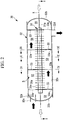
- Fig. 2 is a longitudinal cross-sectional view of the double-pipe heat exchanger 30 illustrated in Fig. 1 .
- Fig. 3 is a cross-sectional view of the double-pipe heat exchanger taken along in the I-I arrow direction in Fig. 2 .
- the double-pipe heat exchanger 30 includes an inner pipe 31, an outer pipe 32 in which the inner pipe 31 is arranged, and partition plates 33 partitioning the inner space SI of the outer pipe 32 into a plurality of divided spaces S1, S2, S3, S4, S5.
- the inner pipe 31 includes a plurality of plate fins 31a arranged in parallel with one another in an axis X extending in the horizontal direction, and includes a refrigerant pipe 31b which allows a refrigerant condensed by the outdoor heat exchanger 23 to pass therethrough.
- the axial direction extending along the axis X coincides with the arrangement direction in which the plurality of plate fins 31a are arranged.
- Each of the plate fins 31a is made of a metallic material such as aluminum and has a rectangular shape.
- Each of the plate fins 31a is preferably formed of a metallic material having a thickness of 0.1 to 0.35 mm.
- the refrigerant pipe 31b is formed of copper, for example.
- a plurality of grooves each formed into a spiral shape along a refrigerant flow direction are desirably formed in the inner circumferential surface of the refrigerant pipe 31b.
- a refrigerant condensed by the outdoor heat exchanger 23 flows in from the right side toward the left side of the refrigerant pipe 31b in the inner pipe 31.
- the refrigerant pipe 31b has a structure of dividing a refrigerant flowing through a single flow path, into two branch flow paths on the upper and lower sides and combining the divided refrigerants together into a single flow path again.
- the lower side flow path has a structure of dividing a single flow path into four branch flow paths in the horizontal direction, which is orthogonal to the axis X, and combining the four branch flow paths to a single flow path again.
- the upper side flow path illustrated in Fig. 2 also has a structure of dividing a single flow path into four branch flow paths in the horizontal direction, which is orthogonal to the axis X, and combining the four branch flow paths to a single flow path again.
- a single flow path is divided into two branch flows paths on the upper and lower sides and each of the branched flow paths is divided into four branch flow paths, so that the single flow path is divided into eight branch flow paths and the branch flow paths are combined together into a single flow path again.
- Fig. 4 is a cross-sectional view of the double-pipe heat exchanger taken in the II-II arrow direction in Fig. 2 .
- the plate fins 31a have a plurality of insertion holes 31c formed therein.
- the refrigerant pipe 31b is inserted through each of the insertion holes 31c.
- the outer circumferential surface of the refrigerant pipe 31b is in contact with the plate fins 31a via the insertion holes 31c. Accordingly, heat of a refrigerant flowing through the refrigerant pipe 31b is transferred to the plate fins 31a.
- the refrigerant pipes 31b are arranged in a Y1 position (first position) in the vertical direction, and the refrigerant pipes 31b are arranged in a Y2 position (second position) in the vertical direction.
- the horizontal positions of the refrigerant pipes 31b arranged in the Y1 position are different from the horizontal positions of the refrigerant pipe 31b arranged in the Y2 position.
- the reason for this alternate arrangement is to ensure, between the refrigerant pipes 31b arranged at eight points, an interval as wide as possible, and thereby to improve the performance of heat transfer from the refrigerant pipes 31b to the plate fins 31a.
- Bent portions 31d formed at the four corners of each of the rectangular plate fins 31a are described with reference to Fig. 4 and Fig. 5 .
- the plate fin 31a has a rectangular shape having the bent portions 31d at the four corners thereof.
- the shape of the plate fin 31a is a shape obtained by bending the four corners of a rectangular shape the longer side of which has a length of L1 and the shorter side of which has a length of L2.
- Each of the plate fins 31a are made of a metallic material.
- the bent portions 31d are formed by plastically deforming the metallic material along an inner circumferential surface 32e of the outer pipe 32.
- the bent portions 31d are disposed in a state of applying contact forces to the inner circumferential surface 32e of the outer pipe 32. Since the plate fins 31a included in the inner pipe 31 apply, at respective positions along the axis X, contact forces to the inner circumferential surface 32e of the outer pipe 32, the inner pipe 31 is fixed inside of the outer pipe 32.
- the number of the plate fins 31a included in the inner pipe 31 may be an arbitrarily determined number (e.g. several hundreds or so).
- the plate fin 31a each have a rectangular shape the longer side of which has a length of L1 and the shorter side of which has a length of L2. In this state, no bent portions 31d are formed at the four corners of the plate fins 31a.
- a worker to assemble the double-pipe heat exchanger 30 of the present embodiment performs an insertion step of inserting the inner pipe 31 into the outer pipe 32 while plastically deforming the four corners of each of the rectangular plate fins 31a.
- each of the plate fins 31a is changed from the state having no bent portions 31d formed thereon, as illustrated in Fig. 5 , to the state of having the bent portions 31d formed thereon as illustrated in Fig. 4 .
- the length L1 of the longer side of the plate fin 31a is shorter than an inner diameter D of the outer pipe 32. If the length L1 of the longer side of the plate fin 31a is equal to or longer than the inner diameter D of the outer pipe 32, the insertion step of inserting the inner pipe 31 into the outer pipe 32 would be difficult. If the length L1 of the longer side of the plate fin 31a is equal to or longer than the inner diameter D of the outer pipe 32, the entity of the shorter sides come into contact with the inner circumferential surface 32e of the outer pipe 32 and are plastically deformed, in the insertion step. This requires an excessively large force to plastically deform the plate fins 31a. Thus, the insertion step becomes difficult.
- the plate fin 31a may be excessively deformed. In this case, for example, a problem that the heat transfer performance is reduced, or a problem that none of the bent portions 31d to apply appropriate contact forces to the inner circumferential surface 32e of the outer pipe 32 are formed, may be caused.
- the outer pipe 32 is formed into a cylindrical shape extending in the axis X, and allows a refrigerant evaporated by the indoor heat exchanger 12 to flow therethrough.
- the outer pipe 32 has a tubular portion 32a extending in the axis X, and a pair of dished end plates 32b which close both ends, in the axis X, of the tubular portion 32a.
- the pair of dished end plates 32b are bonded to both ends of the tubular portion 32a by brazing.
- the inner space S which is a closed space is formed.
- the outer pipe 32 has the inlet port 32c through which a refrigerant evaporated by the indoor heat exchanger 12 flows into the inner space S, and the outlet port 32d through which the refrigerant flows out of the inner space S.
- the inlet port 32c is connected to the refrigerant pipe 42, and the outlet port 32d is connected to the refrigerant pipe 41.
- the flow direction of a refrigerant flowing through the outer pipe 32 from the inlet port 32c to the outlet port 32d is opposite to the flow direction of a refrigerant flowing through the refrigerant pipe 31b of the inner pipe 31.
- the partition plates 33 are plate members arranged in parallel with one another along the axis X while being in contact with the inner circumferential surface 32e of the outer pipe 32. As illustrated in Fig. 2 , the plurality of partition plates 33 are arranged at a fixed arrangement interval along the axis X.
- Fig. 6 is a cross-sectional view of the double-pipe heat exchanger taken in the III-III arrow direction in Fig. 2 .
- Fig. 7 is a cross-sectional view of the double-pipe heat exchanger taken in the IV-IV arrow direction in Fig. 2 .
- the axis Y extends in the vertical direction.
- each of the partition plates 33 is formed into a shape obtained by partially cutting out a circular plate that has a diameter equal to that of the inner circumferential surface 32e of the outer pipe 32, along a plane orthogonal to the radial direction of the circular plate.
- the partition plates 33 are arranged in contact with the inner circumferential surface 32e of the outer pipe 32, and each have, in the cutout area, an opening portion 33a which allows a refrigerant to pass therethrough.
- the plurality of partition plates 33 have a plurality of insertion holes 33b formed therein. The refrigerant pipe 31b is inserted in the insertion holes 33b.
- the opening portion 33a illustrated in Fig. 6 connects a pair of adjacent divided spaces S3, S4 to each other, and the opening portion 33a illustrated in Fig. 7 connects a pair of adjacent divided spaces S2, S3 to each other.
- the partition plate 33 illustrated in Fig. 6 has the opening portion 33a on the vertically upper side thereof.
- the partition plate 33 illustrated in Fig. 7 has the opening portion 33a on the vertically lower side thereof.
- the plurality of opening portions 33a formed in the plurality of partition plate 33 arranged inside the outer pipe 32 are formed alternately on the vertically upper and lower sides along the axis X.
- two partition plates 33 each having the opening portion 33a on the vertically upper side thereof, each have a cutout portion 33c via which a pair of adjacent divided spaces are connected, at the vertically lower end, to each other.
- the cutout portions 33c are formed in the partition plate 33 arranged between the pair of the adjacent divided spaces S1, S2, and in the partition plate 33 arranged between the pair of the adjacent divided spaces S3, S4.
- the opening area of the cutout portion 33c is sufficiently smaller than the opening area of the opening portion 33a.
- the cutout portions 33c inhibit a refrigerant liquefied inside the outer pipe 32 or a lubricating oil contained in a refrigerant from remaining on the lower end of the outer pipe 32 when the liquefied refrigerant or the lubricating oil is guided to the lower portion of the outer pipe. Even if the liquefied refrigerant or the lubricating oil is guided to the lower end of the outer pipe 32, the liquefied refrigerant or the lubricating oil is guided to the outlet port 32d via the cutout portions 33c.
- Fig. 6 illustrates the partition plate 33 having the opening portion 33a formed on the vertically upper side thereof.
- a partition plate 33A according to a modification illustrated in Fig. 8 having the opening portion 33a on a lateral side thereof may be adopted.
- the partition plate 33A having the opening portion 33a on a lateral side thereof also has the cutout portion 33c formed on the vertically lower end thereof. If the partition plate 33A having the opening portion 33a on a lateral side thereof, is not provided with the cutout portion 33c, the lower end of the outer pipe 32 would be closed.
- the plurality of opening portion 33a formed in the plurality of partition plates 33 arranged inside the outer pipe 32 are desirably formed alternately on the right side and the left side in a direction along the axis X.
- a low-temperature refrigerant evaporated by the indoor heat exchanger 12 flows in a zigzag manner to the right side and the left side in the horizontal direction of the outer pipe 32 and appropriately cools the plurality of plate fins 31a, so that a high-temperature refrigerant condensed by the outdoor heat exchanger 23 is cooled. Consequently, the heat exchange performance of the transportation refrigeration unit 1 is improved.
- the cutout portion 33c is provided to each of the partition plates 33A arranged inside the outer pipe 32. Without the cutout portion 33c provided in the partition plate 33A having the opening portion 33a formed on a lateral side thereof, as illustrated in Fig. 8 , the lower end of the outer pipe 32 would be closed.
- partition plates 33 each having the opening portion 33a in an area excluding the vertically lower end portion of the inner space S, have the respective cutout portions 33c on the vertically lower end.
- the lower end of the outer pipe 32 is prevented from being fully closed so that a liquefied refrigerant or a lubricating oil can be caused to flow on the lower end of the outer pipe 32 via the cutout portions 33c.
- the partition plates 33 having the respective opening portions 33a on the vertically lower end of the inner space S have no cutout portion 33c formed therein.
- the reason for this is that, at the partition plates 33 each having the opening portion 33a on the vertically lower end of the inner space S, a liquefied refrigerant or a lubricating oil on the lower end of the outer pipe 32 flows through these opening portions 33a.
- a high-temperature refrigerant condensed by the outdoor heat exchanger 23 flows through the refrigerant pipe 31b of the inner pipe 31, and a low-temperature refrigerant evaporated by the indoor heat exchanger 12 flows through the inside of the outer pipe 32. Since the inner pipe 31 is arranged inside the outer pipe 32, the low-temperature refrigerant evaporated by the indoor heat exchanger 12 cools the plurality of plate fins 31a of the inner pipe 31 and the high-temperature refrigerant condensed by the outdoor heat exchanger 23 is cooled.
- the inner space S of the outer pipe 32 is partitioned by the plurality of partition plates 33, and the partition plates 33 are provided with the opening portions 33a via which a pair of adjacent divided spaces are connected to each other.
- a low-temperature refrigerant evaporated by the indoor heat exchanger 12 flows in a zigzag manner and appropriately cools the plurality of plate fins 31a, so that a high-temperature refrigerant condensed by the outdoor heat exchanger 23 is cooled. Consequently, the heat exchange performance of the transportation refrigeration unit 1 including the outdoor heat exchanger 23 and the indoor heat exchanger 12 is improved.
- partition plates 33 each having the opening portion 33a in an area excluding the vertically lower end of the inner space S, each have formed the cutout portion 33c via which a pair of adjacent divided spaces are connected, at the lower end, to each other. Therefore, when a refrigerant liquefied in the inner space S of the outer pipe 32 or a lubricating oil contained in a refrigerant is guided to the lower portion of the outer pipe 32, the liquefied refrigerant or the lubricating oil flows through the inner space S via the cutout portions 33c.
- each of the cutout portions 33c is smaller than the opening area of the each of the opening portions 33a, the main flow of a high-temperature refrigerant condensed by the outdoor heat exchanger 23 passes through the plurality of opening portions 33a. Consequently, a problem that a refrigerant liquefied in the inner space S of the outer pipe 32 or a lubricating oil contained in a refrigerant remains in the lower portion of the outer pipe 32, can be suppressed.
- the outer pipe 32 is formed into a cylindrical shape extending in the arrangement direction, and each of the partition plates 33 is formed into a shape obtained by partially cutting out a circular plate. Accordingly, the outer pipe 32 and the partition plates 33 can be formed into relatively simple shapes.
- the plurality of opening portions 33a formed in the partition plates 33 are formed, in the arrangement direction, alternately at vertically upper and lower sides or alternately at horizontally right and left sides.
- a low-temperature refrigerant evaporated by the indoor heat exchanger 12 flows in a zigzag manner alternately to the upper side and the lower side of the outer pipe 32 or alternately to the right side and the left side in the horizontal direction, and appropriately cools the plurality of plate fins 31a, so that a high-temperature refrigerant condensed by the outdoor heat exchanger 23 is cooled. Consequently, the heat exchange performance of the transportation refrigeration unit 1 including the outdoor heat exchanger 23 and the indoor heat exchanger 12 is improved.
- the plurality of partition plates 33 are arranged at a fixed interval in the arrangement direction.
- the heat transfer performance of the plurality of plate fins 31a can be fixed irrespective of the positions thereof in the arrangement direction. Further, the manufacturing cost for the inner pipe 31 can be suppressed.
- the plate fins 31a included in the inner pipe 31 each have the bent portions 31d at the four corners thereof, and the inner pipe 31 is arranged inside the outer pipe 32 while the bent portions 31d are applying contact forces to the inner circumferential surface 32e of the outer pipe 32.
- the bent portions 31d are provided to each of the plate fins 31a for enhancing the heat transfer performance of a refrigerant flowing through the inner pipe 31, and the bent portions 31d fix the inner pipe 31 to the outer pipe 32, so that any work or any component for fixing the inner pipe 31 is not required.
- each of the plate fins 31a arranged in parallel with each other in the arrangement direction applies a contact force. Therefore, even in an environment where a load caused by vibration may be generated (e.g. an environment for the transportation refrigeration unit 1), the inner pipe 31 can be securely fixed to the outer pipe 32.
- the outer pipe 32 is formed into a cylindrical shape extending in the arrangement direction, and the longer side of each of the plate fins 31a has a length shorter than the inner diameter D of the outer pipe 32.
- the length L1 of the longer side of each of the plate fins 31a is made shorter than the inner diameter D of the outer pipe 32.
- each of the plate fins 31a is formed of a metallic material having a thickness of 0.1 to 0.35 mm.
- the heat transfer performance of the plate fins 31a can be ensured, and a reaction force generated when the bent portions 31d are formed during insertion of the rectangular plate fins 31a in the outer pipe 32, can be reduced.
- a flow path cross-sectional area A obtained by subtracting the area of each of the plate fins 31a from the opening area, of the outer pipe 32, in the vertical plane orthogonal to the arrangement direction, is greater than two times of a second flow path cross-sectional area B at the inlet port 32c or the outlet port 32d.
- the flow path cross-sectional area A of a portion of the outer pipe 32 where the plate fin 31a is arranged is ensured to be equal to or larger than the flow path cross-sectional area B at the inlet port 32c or the outlet port 32d, occurrence of the pressure loss of a refrigerant flowing through the inner space S of the outer pipe 32 after having been evaporated by the indoor heat exchanger 12 can be reliably inhibited.
- the refrigerant pipe 31b has a structure of dividing a refrigerant flowing through a single flow path, into a plurality of branch flow paths and combining the divided refrigerants together into a single flow path again.
- the double-pipe heat exchanger 30 of the present embodiment in a predetermined position in the arrangement direction, the plurality of refrigerant pipes 31b are arranged in the Y1 position in the vertical direction, and the plurality of refrigerant pipes 31b are arranged in the Y2 position in the vertical direction.
- the horizontal positions of the refrigerant pipes 31b arranged in the Y1 position are different from the horizontal positions of the refrigerant pipe 31b arranged in the Y2 position.
- the flow direction of a refrigerant flowing through the outer pipe 32 from the inlet port 32c to the outlet port 32d is opposite to the flow direction of a refrigerant flowing through the inner pipe 31.
- the flow direction of the refrigerant flowing through the outer pipe 32 is made opposite to the flow direction of the refrigerant flowing through inner pipe 31. Consequently, the heat exchange performance of the double-pipe heat exchanger 30 is improved.
- the plurality of partition plates 33 are arranged at a fixed interval along the axis X, as illustrated in Fig. 2 .
- another form may be used for the plurality of partition plates 33.
- an interval on the inlet port 32c side (upstream side in the arrangement direction) in a direction along the axis X, at which the plurality of partition plates 33 are arranged may be smaller than that on the outlet port 32d side (downstream side in the arrangement direction) in the direction along the axis X.
- a low-temperature refrigerant having flowed in from the inlet port 32c expands through heat exchange with a high-temperature refrigerant flowing through the refrigerant pipe 31b of the inner pipe 31. Therefore, the arrangement interval of the partition plates 33 on the inlet port 32c side (upstream side in the arrangement direction) is made narrower than that on the outlet port 32d side (downstream side in the arrangement direction), so that the pressure loss of a refrigerant flowing through the inner space S of the outer pipe 32 can be inhibited from increasing on the outlet port 32d side.
- the refrigerant pipe 31b of the inner pipe 31 has a structure of dividing a single flow path into a plurality of branch flow paths and combining the divided branch flow paths together into a single flow path again.
- a double-pipe heat exchanger 30A according to a modification illustrated in Fig. 9 , may be adopted which includes an inner pipe 31A having a plurality of independent refrigerant flow paths each of which allows a refrigerant to flow therethrough from an inlet port on the right side to an outlet port on the left side.
- Fig. 9 illustrates the inner pipe 31A including two independent refrigerant flow paths.
- the inner pipe 31A may include an arbitrarily defined number, which is three or greater, of refrigerant flow paths.
- a double-pipe heat exchanger 30B according to a modification illustrated in Fig. 10 may be adopted in which an inner pipe 31B causes a refrigerant to flow in from one of both ends, in the arrangement direction, of the outer pipe 32 into the inner space S of the outer pipe 32 and causes the refrigerant to flow out from the one end to the outside of the outer pipe 32.
- the 10 has a structure of causing a refrigerant to flow into a single flow path from the right side of the outer pipe 32, dividing the refrigerant into a plurality of branch flow paths, combining the divided refrigerants together into a single flow path again, and causing the combined refrigerant to flow out from the right side of the outer pipe 32.
- the position at which a refrigerant is caused to flow to the inside of the outer pipe 32 through the inner pipe 31B is set to the same position as the position at which the refrigerant is caused to flow out from the inner pipe 31B to the outside of the outer pipe 32. Consequently, the space for installing the double-pipe heat exchanger 30B can be reduced.
- the configuration of the partition plates is not limited to that of the aforementioned embodiment of the present invention.
Landscapes
- Engineering & Computer Science (AREA)
- Physics & Mathematics (AREA)
- Thermal Sciences (AREA)
- Mechanical Engineering (AREA)
- General Engineering & Computer Science (AREA)
- Geometry (AREA)
- Heat-Exchange Devices With Radiators And Conduit Assemblies (AREA)
Abstract
Description
- The present invention relates to a double-pipe heat exchanger, a heat exchange system provided with the same, and a method for assembling the double-pipe heat exchanger.
- A double-pipe heat exchanger in which an inner pipe and an outer pipe are coaxially arranged and a heat exchange medium flowing space is formed between these pipes, has been conventionally known (for example, see PTL 1). In a double-pipe heat exchanger disclosed in
PTL 1, disc-like fins are disposed between an inner pipe and an outer pipe, some of the disc-like fins have respective cutout portions for allowing a heat exchange medium to flow therethrough, and the inner pipe and the outer pipe are bonded together with an aluminum brazing material at both left and right ends thereof. - [PTL 1]
Japanese Unexamined Utility Model Application, Publication No.Hei 07-42406 - In
PTL 1, however, among the disc-like fins disposed between the inner pipe and the outer pipe, a disc-like fin that has a cutout portion formed on the upper side thereof closes the vertically lower end of the inner space of the outer pipe. Accordingly, for example, when a heat exchange medium is liquefied inside the outer pipe, the liquefied heat exchange medium remains in the lower portion of the outer pipe. - Moreover, in
PTL 1, the aluminum brazing material is required to fix the inner pipe to the outer pipe, and further, the work for inserting the inner pipe in the outer pipe needs to be followed by an additional work for bonding the inner pipe and the outer pipe together by brazing. - The present invention has been made in view of the above circumstances, and an object thereof is to provide a double-pipe heat exchanger in which a problem that a refrigerant having been liquefied inside an outer pipe or a lubricating oil contained in a refrigerant remains in the lower portion of the outer pipe, is suppressed, and to provide a heat exchange system provided with the double-pipe heat exchanger.
- Another object of the present invention is to provide a double-pipe heat exchanger in which an inner pipe can be securely fixed to an outer pipe without involving any work or any component for fixing the inner pipe, to provide a heat exchange system provided with the double-pipe heat exchanger, and to provide a method for assembling the double-pipe heat exchanger.
- In order to solve the above problems, the present invention adopts the following means.
- A double-pipe heat exchanger according to one aspect of the present invention includes:
- an inner pipe including a plurality of plate fins which are arranged in parallel with one another in an arrangement direction and a refrigerant pipe which is inserted in through holes formed in the plate fins and which allows a refrigerant condensed by a condenser to flow therethrough;
- an outer pipe which is formed into a tubular shape extending in the arrangement direction and which allows a refrigerant evaporated by an evaporator to flow therethrough; and
- a plurality of partition plates which are arranged in parallel with one another in the arrangement direction while being in contact with an inner circumferential surface of the outer pipe and which partition an inner space of the outer pipe into a plurality of divided spaces, wherein
- the inner pipe is arranged inside the outer pipe,
- the partition plates each have formed therein an opening portion via which a pair of adjacent divided spaces are connected to each other,
- a partition plate having the opening portion formed in an area excluding a vertically lower end of the inner space, has formed therein a cutout portion via which a pair of adjacent divided spaces are connected, at the lower end, to each other, and
- the cutout portion has an opening area smaller than that of the opening portion.
- In the double-pipe heat exchanger according to the one aspect of the present invention, a high-temperature refrigerant condensed by the condenser flows through the refrigerant pipe of the inner pipe, and a low-temperature refrigerant evaporated by the evaporator flows through the inside of the outer pipe. Since the inner pipe is arranged inside the outer pipe, the low-temperature refrigerant evaporated by the evaporator cools the plurality of plate fins of the inner pipe and the high-temperature refrigerant condensed by the condenser is cooled. Further, the inner space of the outer pipe is partitioned by the plurality of partition plates, and the partition plates each have the opening portion via which a pair of adjacent divided spaces are connected to each other. Accordingly, when passing through the plurality of divided spaces formed by the partition plates, the low-temperature refrigerant evaporated by the evaporator flows in a zigzag manner, and appropriately cools the plurality of plate fins. Consequently, the heat exchange performance of the heat exchange system including the condenser and the evaporator is improved.
- Furthermore, in the double-pipe heat exchanger according to the one aspect of the preset invention, among the plurality of partition pates, a partition plate having the opening portion formed in an area excluding the vertically lower end of the inner space, has formed therein a cutout portion via which a pair of adjacent divided spaces are connected, at the lower end, to each other. Accordingly, when a refrigerant liquefied in the inner space of the outer pipe or a lubricating oil contained in a refrigerant is guided to the lower portion of the outer pipe, the liquefied refrigerant or the lubricating oil flows through the inner space via the cutout portions. Here, since the opening area of the cutout portion is smaller than the opening area of the corresponding opening portion, the main flow of the high-temperature refrigerant condensed by the condenser passes through a plurality of the opening portion. Consequently, a problem that a refrigerant liquefied in the inner space of the outer pipe or a lubricating oil contained in a refrigerant remains in the lower portion of the outer pipe, can be suppressed.
- In the double-pipe heat exchanger according to the one aspect of the present invention, the outer pipe may be formed into a cylindrical shape in the arrangement direction, and each of the partition plates may be formed into a shape obtained by partially cutting out a circular plate.
- As a result of this, the outer pipe and the partition plates can be formed into relatively simple shapes.
- In the double-pipe heat exchanger according to the one aspect of the present invention, the opening portions formed in the plurality of partition plates may be configured to be formed alternately, in the arrangement direction, at vertically upper and lower sides or horizontally right and left sides.
- With this configuration, when passing through the plurality of divided spaces formed by the partition plates, a low-temperature refrigerant evaporated by the evaporator flows in a zigzag manner to the upper and lower sides or the horizontally right and left sides of the outer pipe, and thus, appropriately cools the plurality of plate fins. Consequently, the heat exchange performance of the heat exchange system including the condenser and the evaporator is improved.
- In the double-pipe heat exchanger configured as above, the plurality of partition plates may be arranged at a fixed interval in the arrangement direction.
- As a result of this, the heat transfer performance of the plurality of plate fins can be fixed irrespective of the positions thereof in the arrangement direction. Moreover, the manufacturing cost for the inner pipe can be suppressed.
- In the double-pipe heat exchanger configured as above, the outer pipe may include an inlet port through which an refrigerant evaporated by the evaporator flows in from an upstream side in the arrangement direction, and an outlet port through which the refrigerant flows out from a downstream side in the arrangement direction, and an arrangement interval on a downstream side in the arrangement direction, at which the plurality of partition plates are arranged in the arrangement direction, is larger than that on an upstream side in the arrangement direction.
- A low-temperature refrigerant having flowed in from the inlet port, expands through heat exchange with a high-temperature refrigerant flowing through the refrigerant pipe of the inner pipe, so that the average flow rate of a refrigerant flow behind the double-pipe heat exchanger is increased. Therefore, the arrangement interval of the partition plates on the downstream side in the arrangement direction, is made larger than that on the upstream side in the arrangement direction, so that the refrigerant flowing though the outer pipe side can pass through the double-pipe heat exchanger without involving an increase in the average flow rate. Consequently, the pressure loss of the refrigerant flowing through the inside of the outer pipe can be inhibited from increasing on the downstream side in the arrangement direction.
- A double-pipe heat exchanger according to another aspect of the present invention includes:
- an inner pipe including a plurality of plate fins which are arranged in parallel with one another in an arrangement direction and a refrigerant pipe which is inserted in through holes formed in the plate fins and which allows a refrigerant condensed by a condenser to flow therethrough; and
- an outer pipe which is formed into a tubular shape extending in the arrangement direction and which allows a refrigerant evaporated by an evaporator to flow therethrough, wherein
- the plate fins are each formed into a rectangular shape having bent portions at four corners thereof, and
- the inner pipe is arranged inside the outer pipe while the bent portions are applying contact forces to an inner circumferential surface of the outer pipe.
- In the double-pipe heat exchanger according to the another aspect of the present invention, a high-temperature refrigerant condensed by the condenser flows through the refrigerant pipe of the inner pipe, and a low-temperature refrigerant evaporated by the evaporator flows through the inside of the outer pipe. Since the inner pipe is arranged inside the outer pipe, the low-temperature refrigerant evaporated by the evaporator cools the plurality of plate fins of the inner pipe, and the high-temperature refrigerant condensed by the condenser is cooled.
- In the double-pipe heat exchanger according to the another aspect of the present invention, each of the plate fins included in the inner pipe has the bent portions at the four corners thereof. While the bent portions are applying contact forces to the inner circumferential surface of the outer pipe, the inner pipe is arranged inside the outer pipe. The bent portions are provided to the plate fins for enhancing the heat transfer performance of a refrigerant flowing through the inner pipe, and the inner pipe is fixed to the outer pipe by the bent portions, so that any work or any component for fixing the inner pipe is not required. Moreover, each of the plate fins arranged, in the arrangement direction, in parallel with one another, applies a contact force. Therefore, even in an environment where a load caused by vibration may be generated (e.g. an environment for the transportation refrigeration unit), the inner pipe can be securely fixed to the outer pipe.
- In the double-pipe heat exchanger according to the another aspect of the present invention, the outer pipe may be formed into a cylindrical shape in the arrangement direction, and each of the plate fins may have a longer side having a length shorter than an inner diameter of the outer pipe.
- The length of the longer side of each of the plate fins is shorter than the inner diameter of the outer pipe. Accordingly, while portions of the shorter sides of the plate fins are not in contact with the inner circumferential surface of the outer pipe, the remaining portions of the shorter sides are, as the bent portions, in contact with the inner circumferential surface of the outer pipe. Consequently, at the bent portions at the four corners of each of the plate fins, the contact forces to the inner circumferential surface of the outer pipe can be reliably generated. Moreover, in a case where the bent portions are formed by insertion of the rectangular plate fins in the outer pipe, a reaction force generated during insertion of the plate fins in the outer pipe, can be reduced. Consequently, the insertion work can be easily performed.
- In the double-pipe heat exchanger according to the another aspect of the present invention, each of the plate fins may be formed of a metallic material having a thickness of 0.1 to 0.35 mm.
- As a result of this, the heat transfer performance of the plate fins can be ensured, and a reaction force generated when the bent portions are formed by insertion of the rectangular plate fins in the outer pipe, can be reduced.
- In the double-pipe heat exchanger according to the above aspect of the present invention, the outer pipe may include an inlet port through which a refrigerant evaporated by the evaporator flows in, and an outlet port through which the refrigerant flows out, and a first flow path cross-sectional area obtained by subtracting the area of each of the plate fins from the opening area, of the outer pipe, in a vertical plane orthogonal to the arrangement direction, may be greater than two times of a second flow path cross-sectional area at each of the inlet port and the outlet port.
- The first flow path cross-sectional area of the portion, of the outer pipe, where the plate fins are arranged is ensured to be equal to or larger than the second flow path cross-sectional area of each of the inlet port and the outlet port. Accordingly, occurrence of the pressure loss of a refrigerant flowing through the inner space of the outer pipe after having been evaporated by the evaporator can be reliably inhibited.
- In the double-pipe heat exchanger according to the above aspect of the present invention, the outer pipe may include an inlet port through which the refrigerant evaporated by the evaporator flows in, and an outlet port through which the refrigerant flows out, and the refrigerant pipe may be configured to have a structure of dividing a refrigerant flowing through a single flow path, into a plurality of branch flow paths and combining the divided refrigerants together into a single flow path again.
- As a result of the configuration in which a single flow path is divided into a plurality of branch flow paths, and the branch flow paths are combined together into a single flow path again, the surface area of the refrigerant pipe can be increased so that the heat transfer performance of the inner pipe can be improved.
- In the double-pipe heat exchanger according to the above aspect of the present invention, the outer pipe may include an inlet port through which a refrigerant evaporated by the evaporator flows in, and an outlet port through which the refrigerant flows out, and the inner pipe may be configured to have a plurality of refrigerant flow paths which allow a refrigerant to flow from the inlet port to the outlet port through the refrigerant pipe.
- The plurality of refrigerant flow paths which allow a refrigerant to flow from the inlet port to the outlet port through the refrigerant pipe are provided. Accordingly, the surface area of the refrigerant pipe can be increased so that the heat transfer performance of the inner pipe can be improved.
- In the double-pipe heat exchanger configured as above, in a predetermined position in the arrangement direction, a plurality of the refrigerant pipes may be arranged in a first position in a vertical direction, a plurality of the refrigerant pipes may be arranged in a second position in the vertical direction, and horizontal positions of the refrigerant pipes arranged in the first position may be different from horizontal positions of the refrigerant pipes arranged in the second position.
- The refrigerant pipes which are arranged in the first position in the vertical direction and the refrigerant pipes which are arranged in the second position in the vertical direction are disposed in horizontally different positions. Consequently, the heat transfer performance of the inner pipe can be improved.
- In the double-pipe heat exchanger configured as above, a flow direction of a refrigerant flowing through the outer pipe from the inlet port to the outlet port may be opposite to a flow direction of a refrigerant flowing through the inner pipe.
- The flow direction of the refrigerant flowing through the outer pipe is opposite to the flow direction of the refrigerant flowing through the inner pipe. Accordingly, the heat exchange performance of the double-pipe heat exchanger can be improved.
- In the double-pipe heat exchanger configured as above, the inner pipe may cause a refrigerant to flow into an inside of the outer pipe from one of both ends, in the arrangement direction, of the outer pipe, and cause the refrigerant to flow out from the one end to an outside of the outer pipe.
- The position at which a refrigerant may be caused to flow to the inside of the outer pipe by the inner pipe is set to the same position as the position at which the refrigerant is caused to flow out from the inner pipe to the outside of the outer pipe, so that pipes in the vicinity of the double-pipe heat exchanger can be collected on one end side. Consequently, the space for installing the double-pipe heat exchanger can be reduced.
- In the double-pipe heat exchanger according to the above aspect of the present invention, the outer pipe may have a tubular portion extending in the arrangement direction and a pair of dished end plates which close both ends of the tubular portion.
- As a result of this, the outer pipe can be formed into a relatively simple structure in which the tubular portion and the pair of dished end plates are combined.
- In the double-pipe heat exchanger according to the above aspect of the present invention, a plurality of grooves each formed into a spiral shape in a refrigerant flow direction may be formed in the inner circumferential surface of the refrigerant pipe.
- As a result of this, the performance of heat transfer from the refrigerant to the refrigerant pipe is improved, and thus, the heat exchange performance of the double-pipe heat exchanger is improved.
- A heat exchange system according to still another aspect of the present invention includes:
- a compressor which compresses a refrigerant;
- a condenser which liquefies the refrigerant compressed by the compressor;
- an expansion valve which reduces pressure of the refrigerant liquefied by the condenser;
- an evaporator which evaporates the refrigerant having passed through the expansion valve and supplies the evaporated refrigerant to the compressor; and
- any one of the aforementioned double-pipe heat exchangers, which performs heat exchange between the refrigerant condensed by the condenser and the refrigerant evaporated by the evaporator.
- A method according to yet another aspect of the present invention, is for assembling a double-pipe heat exchanger including an inner pipe which allows a refrigerant condensed by a condenser to flow therethrough and an outer pipe which allows a refrigerant evaporated by an evaporator to flow therethrough,
the inner pipe including a plurality of plate fins which are arranged in parallel with one another in an arrangement direction and a refrigerant pipe which is inserted in through holes formed in the plate fins and which allows a refrigerant condensed by the condenser to flow therethrough,
the outer pipe being formed into a tubular shape extending in the arrangement direction and being configured to allow a refrigerant evaporated by the evaporator to flow therethrough, the method comprising
an insertion step of inserting the inner pipe in the outer pipe while plastically deforming four corners of each of the plurality of rectangular-shaped plate fins. - In the method for assembling a double-pipe heat exchanger according to yet another aspect of the present invention, during insertion of the inner pipe into the outer pipe, the four corners of each of the plurality of rectangular plate fins are plastically deformed. Accordingly, the bent portions at the four corners of each of the plate fins are formed by the insertion work. When the insertion work is completed, the bent portions are in a state of applying contact forces to the inner circumferential surface of the outer pipe. Accordingly, any additional work or any additional component for fixing the inner pipe is not needed. Further, the plurality of plate fins arranged in parallel with one another each apply a contact force. Therefore, even in an environment where a load caused by vibration may be generated (e.g. an environment for the transportation refrigeration unit), the inner pipe can be securely fixed to the outer pipe.
- The present invention can provide a double-pipe heat exchanger in which a refrigerant liquefied inside an outer pipe or a lubricating oil contained in a refrigerant is inhibited from remaining in the lower portion of the outer pipe, and provide a heat exchange system provided with the double-pipe heat exchanger.
- The present invention can further provide a double-pipe heat exchanger in which an inner pipe can be securely fixed to an outer pipe without involving any work or any component for fixing the inner pipe, a heat exchange system provided with the double-pipe heat exchanger, and a method for assembling the double-pipe heat exchanger.
-
- [
Fig. 1] Fig. 1 is a schematic configuration diagram of an air conditioner according to one embodiment of the present invention. - [
Fig. 2] Fig. 2 is a longitudinal cross-sectional view of a double-pipe heat exchanger inFig. 1 . - [
Fig. 3] Fig. 3 is a cross-sectional view of the double-pipe heat exchanger taken in the I-I arrow direction inFig. 2 . - [
Fig. 4] Fig. 4 is a cross-sectional view of the double-pipe heat exchanger taken in the II-II arrow direction inFig. 2 . - [
Fig. 5] Fig. 5 is a diagram illustrating a state prior to insertion of plate fins inFig. 4 into an outer pipe. - [
Fig. 6] Fig. 6 is a cross-sectional view of the double-pipe heat exchanger taken in the III-III arrow direction inFig. 2 . - [
Fig. 7] Fig. 7 is a cross-sectional view of the double-pipe heat exchanger taken in the IV-IV arrow direction inFig. 2 . - [
Fig. 8] Fig. 8 is a diagram illustrating a modification of a partition plate illustrated inFig. 7 . - [
Fig. 9] Fig. 9 is a longitudinal cross-sectional view illustrating a modification of the double-pipe heat exchanger. - [
Fig. 10] Fig. 10 is a transverse cross-sectional view illustrating another modification of the double-pipe heat exchanger. - Hereinafter, one embodiment of the present invention is described with reference to the drawings.
-
Fig. 1 illustrates a schematic configuration diagram of a transportation refrigeration unit (heat exchange system) 1 according to one embodiment of the present invention. Thetransportation refrigeration unit 1 illustrated inFig. 1 is mounted in a vehicle 2. The vehicle 2 includes thetransportation refrigeration unit 1, acold storage 3 having a front wall upper portion to which thetransportation refrigeration unit 1 is attached, acabin 4 which an occupant of the vehicle 2 gets in, and anengine 5 which is disposed below thecabin 4 and which serves as a drive source for causing the vehicle 2 to travel. - The vehicle 2 has a configuration with the
cold storage 3 mounted on a chassis behind thecabin 4. Thecold storage 3 is formed of a box body having a heat insulating structure, and has a door (not illustrated) through which loads are carried in/out is provided to the rear side or a lateral side of thecold storage 3. When the door through which loads are carried in/out is closed, thecold storage 3 enters an enclosed state in which the inner space thereof is shut off from outside air. - The
transportation refrigeration unit 1 includes anindoor refrigerating unit 10 in which heat exchange is performed between a refrigerant and internal air in thecold storage 3, anoutdoor refrigerating unit 20 in which heat exchange is performed between a refrigerant and outside air, a double-pipe heat exchanger 30, and arefrigerant circuit 40. - The
indoor refrigerating unit 10 is provided with, in abody part 11, an indoor heat exchanger (evaporator) 12, anexpansion valve 13, and an indoorheat exchange fan 14. Theoutdoor refrigerating unit 20 is provided with, in abody part 21, acompressor 22, an outdoor heat exchanger (condenser) 23, and an outdoorheat exchange fan 24. - The
indoor refrigerating unit 10 is disposed on the upper side of the front wall of thecold storage 3. Theoutdoor refrigerating unit 20 is disposed on the lower side of thecold storage 3. Anoutdoor heat exchanger 23 of theoutdoor refrigerating unit 20 and theexpansion valve 13 of theindoor refrigerating unit 10 are connected with each other via arefrigerant pipe 41 so as to cause a refrigerant to flow therebetween. Theindoor heat exchanger 12 of theindoor refrigerating unit 10 and thecompressor 22 of theoutdoor refrigerating unit 20 are connected with each other via arefrigerant pipe 42 so as to cause a refrigerant to flow therebetween. Therefrigerant circuit 40 which causes a refrigerant to circulate through thecompressor 22, theoutdoor heat exchanger 23, theexpansion valve 13, theindoor heat exchanger 12, and thecompressor 22, in this order is configured by connection between theindoor refrigerating unit 10 and theoutdoor refrigerating unit 20 via therefrigerant pipes - The set position of the
outdoor refrigerating unit 20 is a portion on the lower side of thecold storage 3, but another aspect may be adopted therefor. For example, a structure identical to that of theoutdoor refrigerating unit 20 may be provided on the upper side of the front wall of thecold storage 3 so as to be integrated with theindoor refrigerating unit 10. - In the
transportation refrigeration unit 1, high temperature and high pressure refrigerant gas having undergone compression at thecompressor 22 for compressing refrigerants, is supplied, via arefrigerant pipe 43, to theoutdoor heat exchanger 23 for liquefying refrigerant gas. The refrigerant gas supplied to theoutdoor heat exchanger 23, is liquefied by being condensed through heat exchange with the outside air sent from the outdoorheat exchange fan 24. The liquefied refrigerant liquefied by theoutdoor heat exchanger 23 is supplied, via therefrigerant pipe 41, from theoutdoor heat exchanger 23 to theexpansion valve 13 which reduces refrigerant pressure. Theexpansion valve 13 reduces the pressure of the refrigerant by adiabatic expansion, and the refrigerant the pressure of which has been reduced is supplied to theindoor heat exchanger 12 via arefrigerant pipe 44. Theindoor heat exchanger 12 evaporates the refrigerant supplied from theexpansion valve 13, and supplies the evaporated refrigerant to thecompressor 22. - The refrigerant supplied to the
indoor heat exchanger 12 is evaporated and gasified through heat exchange with internal air sent by the indoorheat exchange fan 14. The internal air cooled at theindoor heat exchanger 12 is blown off into thecold storage 3 so as to be used for cooling thecold storage 3. The refrigerant gasified at theindoor heat exchanger 12 is supplied to thecompressor 22 of theoutdoor refrigerating unit 20 via therefrigerant pipe 42. The refrigerant supplied to thecompressor 22 is compressed again to be converted into high-temperature and high-pressure refrigerant gas. Thetransportation refrigeration unit 1 of the present embodiment causes circulation of a refrigerant through thecompressor 22, theoutdoor heat exchanger 23, theexpansion valve 13, theindoor heat exchanger 12, and thecompressor 22 in this order, and thereby performs cooling operation for cooling thecold storage 3. - The double-
pipe heat exchanger 30 performs heat exchange between a refrigerant condensed by theoutdoor heat exchanger 23 and a refrigerant evaporated by theindoor heat exchanger 12. The double-pipe heat exchanger 30 cools a refrigerant condensed by theoutdoor heat exchanger 23, by using a refrigerant gas evaporated by theindoor heat exchanger 12, and thereby, improves the heat exchange performance of thetransportation refrigeration unit 1. - Next, the structure of the double-
pipe heat exchanger 30 is described in detail with reference to the drawings. -
Fig. 2 is a longitudinal cross-sectional view of the double-pipe heat exchanger 30 illustrated inFig. 1 .Fig. 3 is a cross-sectional view of the double-pipe heat exchanger taken along in the I-I arrow direction inFig. 2 . - As illustrated in the longitudinal cross-sectional view of
Fig. 2 , the double-pipe heat exchanger 30 includes aninner pipe 31, anouter pipe 32 in which theinner pipe 31 is arranged, andpartition plates 33 partitioning the inner space SI of theouter pipe 32 into a plurality of divided spaces S1, S2, S3, S4, S5. - The
inner pipe 31 includes a plurality ofplate fins 31a arranged in parallel with one another in an axis X extending in the horizontal direction, and includes arefrigerant pipe 31b which allows a refrigerant condensed by theoutdoor heat exchanger 23 to pass therethrough. The axial direction extending along the axis X coincides with the arrangement direction in which the plurality ofplate fins 31a are arranged. Each of theplate fins 31a is made of a metallic material such as aluminum and has a rectangular shape. Each of theplate fins 31a is preferably formed of a metallic material having a thickness of 0.1 to 0.35 mm. - The
refrigerant pipe 31b is formed of copper, for example. In order to improve the heat transfer performance of the refrigerant to therefrigerant pipe 31b, a plurality of grooves each formed into a spiral shape along a refrigerant flow direction are desirably formed in the inner circumferential surface of therefrigerant pipe 31b. - As indicated by the arrows in
Fig. 2 , a refrigerant condensed by theoutdoor heat exchanger 23 flows in from the right side toward the left side of therefrigerant pipe 31b in theinner pipe 31. As illustrated inFig. 2 , therefrigerant pipe 31b has a structure of dividing a refrigerant flowing through a single flow path, into two branch flow paths on the upper and lower sides and combining the divided refrigerants together into a single flow path again. As illustrated inFig. 3 , the lower side flow path has a structure of dividing a single flow path into four branch flow paths in the horizontal direction, which is orthogonal to the axis X, and combining the four branch flow paths to a single flow path again. - Similar to the lower side flow path, the upper side flow path illustrated in
Fig. 2 also has a structure of dividing a single flow path into four branch flow paths in the horizontal direction, which is orthogonal to the axis X, and combining the four branch flow paths to a single flow path again. As described above, in the structure of therefrigerant pipe 31b of the present embodiment, a single flow path is divided into two branch flows paths on the upper and lower sides and each of the branched flow paths is divided into four branch flow paths, so that the single flow path is divided into eight branch flow paths and the branch flow paths are combined together into a single flow path again. -
Fig. 4 is a cross-sectional view of the double-pipe heat exchanger taken in the II-II arrow direction inFig. 2 . As illustrated inFig. 4 , theplate fins 31a have a plurality ofinsertion holes 31c formed therein. Therefrigerant pipe 31b is inserted through each of theinsertion holes 31c. The outer circumferential surface of therefrigerant pipe 31b is in contact with theplate fins 31a via theinsertion holes 31c. Accordingly, heat of a refrigerant flowing through therefrigerant pipe 31b is transferred to theplate fins 31a. - As illustrated in
Fig. 4 , in a predetermined position along the axis X, therefrigerant pipes 31b are arranged in a Y1 position (first position) in the vertical direction, and therefrigerant pipes 31b are arranged in a Y2 position (second position) in the vertical direction. The horizontal positions of therefrigerant pipes 31b arranged in the Y1 position are different from the horizontal positions of therefrigerant pipe 31b arranged in the Y2 position. The reason for this alternate arrangement is to ensure, between therefrigerant pipes 31b arranged at eight points, an interval as wide as possible, and thereby to improve the performance of heat transfer from therefrigerant pipes 31b to theplate fins 31a. - In the cross section (a cross section, of the
outer pipe 32, in a vertical plane orthogonal to the axis X) illustrated inFig. 4 , when a flow path cross-sectional area (first flow path cross-sectional area) obtained by subtracting the area of theplate fins 31a from the opening area of theouter pipe 32 is defined as A, and the flow path cross-sectional area (second flow path cross-sectional area) of theinlet port 32c or theoutlet port 32d (described later) is defined as B, A>2B is established. Here, the flow path cross-sectional area of theinlet port 32c and the flow path cross-sectional area of theoutlet port 32d are set to be equal to each other. -
Bent portions 31d formed at the four corners of each of therectangular plate fins 31a are described with reference toFig. 4 and Fig. 5 . - As illustrated in
Fig. 4 , in the state where theinner pipe 31 is inserted in theouter pipe 32, theplate fin 31a has a rectangular shape having thebent portions 31d at the four corners thereof. The shape of theplate fin 31a is a shape obtained by bending the four corners of a rectangular shape the longer side of which has a length of L1 and the shorter side of which has a length of L2. Each of theplate fins 31a are made of a metallic material. Thebent portions 31d are formed by plastically deforming the metallic material along an innercircumferential surface 32e of theouter pipe 32. - Accordingly, the
bent portions 31d are disposed in a state of applying contact forces to the innercircumferential surface 32e of theouter pipe 32. Since theplate fins 31a included in theinner pipe 31 apply, at respective positions along the axis X, contact forces to the innercircumferential surface 32e of theouter pipe 32, theinner pipe 31 is fixed inside of theouter pipe 32. The number of theplate fins 31a included in theinner pipe 31 may be an arbitrarily determined number (e.g. several hundreds or so). - As illustrated in
Fig. 5 , in a state prior to insertion of theplate fins 31a into theouter pipe 32, theplate fin 31a each have a rectangular shape the longer side of which has a length of L1 and the shorter side of which has a length of L2. In this state, nobent portions 31d are formed at the four corners of theplate fins 31a. - A worker to assemble the double-
pipe heat exchanger 30 of the present embodiment, performs an insertion step of inserting theinner pipe 31 into theouter pipe 32 while plastically deforming the four corners of each of therectangular plate fins 31a. As a result of the insertion step, each of theplate fins 31a is changed from the state having nobent portions 31d formed thereon, as illustrated inFig. 5 , to the state of having thebent portions 31d formed thereon as illustrated inFig. 4 . - Here, as illustrated in
Fig. 4 and Fig. 5 , the length L1 of the longer side of theplate fin 31a is shorter than an inner diameter D of theouter pipe 32. If the length L1 of the longer side of theplate fin 31a is equal to or longer than the inner diameter D of theouter pipe 32, the insertion step of inserting theinner pipe 31 into theouter pipe 32 would be difficult. If the length L1 of the longer side of theplate fin 31a is equal to or longer than the inner diameter D of theouter pipe 32, the entity of the shorter sides come into contact with the innercircumferential surface 32e of theouter pipe 32 and are plastically deformed, in the insertion step. This requires an excessively large force to plastically deform theplate fins 31a. Thus, the insertion step becomes difficult. - If the entity of the shorter sides is plastically deformed, the
plate fin 31a may be excessively deformed. In this case, for example, a problem that the heat transfer performance is reduced, or a problem that none of thebent portions 31d to apply appropriate contact forces to the innercircumferential surface 32e of theouter pipe 32 are formed, may be caused. - The
outer pipe 32 is formed into a cylindrical shape extending in the axis X, and allows a refrigerant evaporated by theindoor heat exchanger 12 to flow therethrough. Theouter pipe 32 has atubular portion 32a extending in the axis X, and a pair of dishedend plates 32b which close both ends, in the axis X, of thetubular portion 32a. The pair of dishedend plates 32b are bonded to both ends of thetubular portion 32a by brazing. In theouter pipe 32, as a result of bonding of the pair of dishedend plates 32b to thetubular portion 32a, the inner space S which is a closed space is formed. - The
outer pipe 32 has theinlet port 32c through which a refrigerant evaporated by theindoor heat exchanger 12 flows into the inner space S, and theoutlet port 32d through which the refrigerant flows out of the inner space S. Theinlet port 32c is connected to therefrigerant pipe 42, and theoutlet port 32d is connected to therefrigerant pipe 41. The flow direction of a refrigerant flowing through theouter pipe 32 from theinlet port 32c to theoutlet port 32d is opposite to the flow direction of a refrigerant flowing through therefrigerant pipe 31b of theinner pipe 31. - The
partition plates 33 are plate members arranged in parallel with one another along the axis X while being in contact with the innercircumferential surface 32e of theouter pipe 32. As illustrated inFig. 2 , the plurality ofpartition plates 33 are arranged at a fixed arrangement interval along the axis X.Fig. 6 is a cross-sectional view of the double-pipe heat exchanger taken in the III-III arrow direction inFig. 2 .Fig. 7 is a cross-sectional view of the double-pipe heat exchanger taken in the IV-IV arrow direction inFig. 2 . InFig. 6 and Fig. 7 , the axis Y extends in the vertical direction. - As illustrated in
Fig. 6 and Fig. 7 , each of thepartition plates 33 is formed into a shape obtained by partially cutting out a circular plate that has a diameter equal to that of the innercircumferential surface 32e of theouter pipe 32, along a plane orthogonal to the radial direction of the circular plate. Thepartition plates 33 are arranged in contact with the innercircumferential surface 32e of theouter pipe 32, and each have, in the cutout area, anopening portion 33a which allows a refrigerant to pass therethrough. As illustrated inFig. 6 and Fig. 7 , the plurality ofpartition plates 33 have a plurality ofinsertion holes 33b formed therein. Therefrigerant pipe 31b is inserted in the insertion holes 33b. - The
opening portion 33a illustrated inFig. 6 connects a pair of adjacent divided spaces S3, S4 to each other, and theopening portion 33a illustrated inFig. 7 connects a pair of adjacent divided spaces S2, S3 to each other. Thepartition plate 33 illustrated inFig. 6 , has theopening portion 33a on the vertically upper side thereof. On the other hand, thepartition plate 33 illustrated inFig. 7 has theopening portion 33a on the vertically lower side thereof. As illustrated inFig. 2 , the plurality of openingportions 33a formed in the plurality ofpartition plate 33 arranged inside theouter pipe 32 are formed alternately on the vertically upper and lower sides along the axis X. - As illustrated in
Fig. 2 andFig. 6 , among the fourpartition plates 33 included in the double-pipe heat exchanger 30 of the present embodiment, twopartition plates 33 each having the openingportion 33a on the vertically upper side thereof, each have acutout portion 33c via which a pair of adjacent divided spaces are connected, at the vertically lower end, to each other. As illustrated inFig. 2 , thecutout portions 33c are formed in thepartition plate 33 arranged between the pair of the adjacent divided spaces S1, S2, and in thepartition plate 33 arranged between the pair of the adjacent divided spaces S3, S4. As illustrated inFig. 6 , the opening area of thecutout portion 33c is sufficiently smaller than the opening area of theopening portion 33a. - The
cutout portions 33c inhibit a refrigerant liquefied inside theouter pipe 32 or a lubricating oil contained in a refrigerant from remaining on the lower end of theouter pipe 32 when the liquefied refrigerant or the lubricating oil is guided to the lower portion of the outer pipe. Even if the liquefied refrigerant or the lubricating oil is guided to the lower end of theouter pipe 32, the liquefied refrigerant or the lubricating oil is guided to theoutlet port 32d via thecutout portions 33c. The reason why the twopartition plates 33 each having the openingportion 33a on the vertically upper side thereof have thecutout portions 33c formed therein, is that the lower end of theouter pipe 32 would be closed without thecutout portions 33c in these twopartition plates 33. Here, the lubricating oil contained in a refrigerant is used for lubricating a compressing mechanism (not illustrated) of thecompressor 22. -
Fig. 6 illustrates thepartition plate 33 having the openingportion 33a formed on the vertically upper side thereof. However, another aspect may be adopted for thepartition plate 33. For example, apartition plate 33A according to a modification illustrated inFig. 8 , having the openingportion 33a on a lateral side thereof may be adopted. Thepartition plate 33A having the openingportion 33a on a lateral side thereof, also has thecutout portion 33c formed on the vertically lower end thereof. If thepartition plate 33A having the openingportion 33a on a lateral side thereof, is not provided with thecutout portion 33c, the lower end of theouter pipe 32 would be closed. - In the case where the
partition plate 33A having the openingportion 33a on a lateral side thereof is provided, the plurality of openingportion 33a formed in the plurality ofpartition plates 33 arranged inside theouter pipe 32 are desirably formed alternately on the right side and the left side in a direction along the axis X. Thus, when passing through the plurality of divided spaces formed by thepartition plate 33A, a low-temperature refrigerant evaporated by theindoor heat exchanger 12 flows in a zigzag manner to the right side and the left side in the horizontal direction of theouter pipe 32 and appropriately cools the plurality ofplate fins 31a, so that a high-temperature refrigerant condensed by theoutdoor heat exchanger 23 is cooled. Consequently, the heat exchange performance of thetransportation refrigeration unit 1 is improved. - Also, in the case where a plurality of the
partition plates 33A each having the openingportion 33a on a lateral side thereof are provided, thecutout portion 33c is provided to each of thepartition plates 33A arranged inside theouter pipe 32. Without thecutout portion 33c provided in thepartition plate 33A having the openingportion 33a formed on a lateral side thereof, as illustrated inFig. 8 , the lower end of theouter pipe 32 would be closed. - Thus, among the plurality of
partition plates 33 arranged inside theouter pipe 32,partition plates 33 each having the openingportion 33a in an area excluding the vertically lower end portion of the inner space S, have therespective cutout portions 33c on the vertically lower end. As a result, the lower end of theouter pipe 32 is prevented from being fully closed so that a liquefied refrigerant or a lubricating oil can be caused to flow on the lower end of theouter pipe 32 via thecutout portions 33c. - The
partition plates 33 having therespective opening portions 33a on the vertically lower end of the inner space S, have nocutout portion 33c formed therein. The reason for this is that, at thepartition plates 33 each having the openingportion 33a on the vertically lower end of the inner space S, a liquefied refrigerant or a lubricating oil on the lower end of theouter pipe 32 flows through these openingportions 33a. - The effects to be provided by the present embodiment having described above are described.
- According to the double-
pipe heat exchanger 30 of the present embodiment, a high-temperature refrigerant condensed by theoutdoor heat exchanger 23 flows through therefrigerant pipe 31b of theinner pipe 31, and a low-temperature refrigerant evaporated by theindoor heat exchanger 12 flows through the inside of theouter pipe 32. Since theinner pipe 31 is arranged inside theouter pipe 32, the low-temperature refrigerant evaporated by theindoor heat exchanger 12 cools the plurality ofplate fins 31a of theinner pipe 31 and the high-temperature refrigerant condensed by theoutdoor heat exchanger 23 is cooled. - The inner space S of the
outer pipe 32 is partitioned by the plurality ofpartition plates 33, and thepartition plates 33 are provided with the openingportions 33a via which a pair of adjacent divided spaces are connected to each other. As a result, when flowing through the plurality of divided spaces divided by thepartition plates 33, a low-temperature refrigerant evaporated by theindoor heat exchanger 12 flows in a zigzag manner and appropriately cools the plurality ofplate fins 31a, so that a high-temperature refrigerant condensed by theoutdoor heat exchanger 23 is cooled. Consequently, the heat exchange performance of thetransportation refrigeration unit 1 including theoutdoor heat exchanger 23 and theindoor heat exchanger 12 is improved. - According to the double-
pipe heat exchanger 30 of the present embodiment, among the plurality ofpartition plates 33,partition plates 33 each having the openingportion 33a in an area excluding the vertically lower end of the inner space S, each have formed thecutout portion 33c via which a pair of adjacent divided spaces are connected, at the lower end, to each other. Therefore, when a refrigerant liquefied in the inner space S of theouter pipe 32 or a lubricating oil contained in a refrigerant is guided to the lower portion of theouter pipe 32, the liquefied refrigerant or the lubricating oil flows through the inner space S via thecutout portions 33c. Since the opening area of each of thecutout portions 33c is smaller than the opening area of the each of the openingportions 33a, the main flow of a high-temperature refrigerant condensed by theoutdoor heat exchanger 23 passes through the plurality of openingportions 33a. Consequently, a problem that a refrigerant liquefied in the inner space S of theouter pipe 32 or a lubricating oil contained in a refrigerant remains in the lower portion of theouter pipe 32, can be suppressed. - According to the double-
pipe heat exchanger 30 of the present embodiment, theouter pipe 32 is formed into a cylindrical shape extending in the arrangement direction, and each of thepartition plates 33 is formed into a shape obtained by partially cutting out a circular plate. Accordingly, theouter pipe 32 and thepartition plates 33 can be formed into relatively simple shapes. - According to the double-
pipe heat exchanger 30 of the present embodiment, the plurality of openingportions 33a formed in thepartition plates 33 are formed, in the arrangement direction, alternately at vertically upper and lower sides or alternately at horizontally right and left sides. - Thus, when passing through the plurality of divided spaces S1 to S5 formed by the
partition plate 33, a low-temperature refrigerant evaporated by theindoor heat exchanger 12 flows in a zigzag manner alternately to the upper side and the lower side of theouter pipe 32 or alternately to the right side and the left side in the horizontal direction, and appropriately cools the plurality ofplate fins 31a, so that a high-temperature refrigerant condensed by theoutdoor heat exchanger 23 is cooled. Consequently, the heat exchange performance of thetransportation refrigeration unit 1 including theoutdoor heat exchanger 23 and theindoor heat exchanger 12 is improved. - According to the double-
pipe heat exchanger 30 of the present embodiment, the plurality ofpartition plates 33 are arranged at a fixed interval in the arrangement direction. - As a result of this arrangement, the heat transfer performance of the plurality of
plate fins 31a can be fixed irrespective of the positions thereof in the arrangement direction. Further, the manufacturing cost for theinner pipe 31 can be suppressed. - According to the double-
pipe heat exchanger 30 of the present embodiment, theplate fins 31a included in theinner pipe 31 each have thebent portions 31d at the four corners thereof, and theinner pipe 31 is arranged inside theouter pipe 32 while thebent portions 31d are applying contact forces to the innercircumferential surface 32e of theouter pipe 32. Thebent portions 31d are provided to each of theplate fins 31a for enhancing the heat transfer performance of a refrigerant flowing through theinner pipe 31, and thebent portions 31d fix theinner pipe 31 to theouter pipe 32, so that any work or any component for fixing theinner pipe 31 is not required. Further, each of theplate fins 31a arranged in parallel with each other in the arrangement direction applies a contact force. Therefore, even in an environment where a load caused by vibration may be generated (e.g. an environment for the transportation refrigeration unit 1), theinner pipe 31 can be securely fixed to theouter pipe 32. - According to the double-
pipe heat exchanger 30 of the present embodiment, theouter pipe 32 is formed into a cylindrical shape extending in the arrangement direction, and the longer side of each of theplate fins 31a has a length shorter than the inner diameter D of theouter pipe 32. The length L1 of the longer side of each of theplate fins 31a is made shorter than the inner diameter D of theouter pipe 32. Thus, in the state where theinner pipe 31 is inserted in theouter pipe 32, while portions of the shorter sides of theplate fins 31a are not in contact with the innercircumferential surface 32e of theouter pipe 32, the remaining portions of the shorter sides are, as thebent portions 31d, in contact with the innercircumferential surface 32e of theouter pipe 32. Therefore, at thebent portions 31d on the four corners of each of theplate fins 31a, contact forces to the innercircumferential surface 32e of theouter pipe 32 can be reliably generated. Further, when thebent portions 31d are formed by insertion of therectangular plate fins 31a in theouter pipe 32, a reaction force generated during insertion of theplate fins 31a is reduced. Consequently, the insertion work can be easily performed. - According to the double-
pipe heat exchanger 30 of the present embodiment, each of theplate fins 31a is formed of a metallic material having a thickness of 0.1 to 0.35 mm. - By doing so, the heat transfer performance of the
plate fins 31a can be ensured, and a reaction force generated when thebent portions 31d are formed during insertion of therectangular plate fins 31a in theouter pipe 32, can be reduced. - According to the double-
pipe heat exchanger 30 of the present embodiment, a flow path cross-sectional area A obtained by subtracting the area of each of theplate fins 31a from the opening area, of theouter pipe 32, in the vertical plane orthogonal to the arrangement direction, is greater than two times of a second flow path cross-sectional area B at theinlet port 32c or theoutlet port 32d. - Since the flow path cross-sectional area A of a portion of the
outer pipe 32 where theplate fin 31a is arranged is ensured to be equal to or larger than the flow path cross-sectional area B at theinlet port 32c or theoutlet port 32d, occurrence of the pressure loss of a refrigerant flowing through the inner space S of theouter pipe 32 after having been evaporated by theindoor heat exchanger 12 can be reliably inhibited. - According to the double-
pipe heat exchanger 30 of the present embodiment, therefrigerant pipe 31b has a structure of dividing a refrigerant flowing through a single flow path, into a plurality of branch flow paths and combining the divided refrigerants together into a single flow path again. - As a result of the configuration in which a single flow path is divided into a plurality of branch flow paths, and the branch flow paths are combined together into a single flow path again, the heat transfer performance of the
inner pipe 31 can be improved. - According to the double-
pipe heat exchanger 30 of the present embodiment, in a predetermined position in the arrangement direction, the plurality ofrefrigerant pipes 31b are arranged in the Y1 position in the vertical direction, and the plurality ofrefrigerant pipes 31b are arranged in the Y2 position in the vertical direction. The horizontal positions of therefrigerant pipes 31b arranged in the Y1 position are different from the horizontal positions of therefrigerant pipe 31b arranged in the Y2 position. As a result of this arrangement, the heat transfer performance of theinner pipe 31 can be improved. - According to the double-
pipe heat exchanger 30 of the present embodiment, the flow direction of a refrigerant flowing through theouter pipe 32 from theinlet port 32c to theoutlet port 32d is opposite to the flow direction of a refrigerant flowing through theinner pipe 31. - The flow direction of the refrigerant flowing through the
outer pipe 32 is made opposite to the flow direction of the refrigerant flowing throughinner pipe 31. Consequently, the heat exchange performance of the double-pipe heat exchanger 30 is improved. - In the above explanation, the plurality of
partition plates 33 are arranged at a fixed interval along the axis X, as illustrated inFig. 2 . However, another form may be used for the plurality ofpartition plates 33. For example, an interval on theinlet port 32c side (upstream side in the arrangement direction) in a direction along the axis X, at which the plurality ofpartition plates 33 are arranged, may be smaller than that on theoutlet port 32d side (downstream side in the arrangement direction) in the direction along the axis X. - A low-temperature refrigerant having flowed in from the
inlet port 32c expands through heat exchange with a high-temperature refrigerant flowing through therefrigerant pipe 31b of theinner pipe 31. Therefore, the arrangement interval of thepartition plates 33 on theinlet port 32c side (upstream side in the arrangement direction) is made narrower than that on theoutlet port 32d side (downstream side in the arrangement direction), so that the pressure loss of a refrigerant flowing through the inner space S of theouter pipe 32 can be inhibited from increasing on theoutlet port 32d side. - In the above explanation, the
refrigerant pipe 31b of theinner pipe 31 has a structure of dividing a single flow path into a plurality of branch flow paths and combining the divided branch flow paths together into a single flow path again. However, another aspect may be adopted for therefrigerant pipe 31b. For example, a double-pipe heat exchanger 30A according to a modification illustrated inFig. 9 , may be adopted which includes aninner pipe 31A having a plurality of independent refrigerant flow paths each of which allows a refrigerant to flow therethrough from an inlet port on the right side to an outlet port on the left side.Fig. 9 illustrates theinner pipe 31A including two independent refrigerant flow paths. However, theinner pipe 31A may include an arbitrarily defined number, which is three or greater, of refrigerant flow paths. - Alternatively, for example, a double-
pipe heat exchanger 30B according to a modification illustrated inFig. 10 may be adopted in which aninner pipe 31B causes a refrigerant to flow in from one of both ends, in the arrangement direction, of theouter pipe 32 into the inner space S of theouter pipe 32 and causes the refrigerant to flow out from the one end to the outside of theouter pipe 32. As indicated by the arrows, arefrigerant pipe 31b illustrated inFig. 10 has a structure of causing a refrigerant to flow into a single flow path from the right side of theouter pipe 32, dividing the refrigerant into a plurality of branch flow paths, combining the divided refrigerants together into a single flow path again, and causing the combined refrigerant to flow out from the right side of theouter pipe 32. The position at which a refrigerant is caused to flow to the inside of theouter pipe 32 through theinner pipe 31B is set to the same position as the position at which the refrigerant is caused to flow out from theinner pipe 31B to the outside of theouter pipe 32. Consequently, the space for installing the double-pipe heat exchanger 30B can be reduced. - In the embodiment of the present invention, when the
plate fins 31a are arranged in theinner pipe 31, no bent portion may be provided at the four corners of each of theplate fins 31a. In the case where thebent portions 31d are provided at the four corners of each of theplate fins 31a during arrangement of theplate fins 31a in theinner pipe 31, the configuration of the partition plates is not limited to that of the aforementioned embodiment of the present invention. -
- 1
- transportation refrigeration unit (heat exchange system)
- 2
- vehicle
- 3
- cold storage
- 4
- cabin
- 5
- engine
- 10
- indoor refrigerating unit
- 11
- body part
- 12
- indoor heat exchanger (evaporator)
- 13
- expansion valve
- 14
- indoor heat exchange fan
- 20
- outdoor refrigerating unit
- 21
- body part
- 22
- compressor
- 23
- outdoor heat exchanger (condenser)
- 24
- outdoor heat exchange fan
- 30, 30A, 30B
- double-pipe heat exchanger
- 31, 31A, 31B
- inner pipe
- 31a
- plate fin
- 31b
- refrigerant pipe
- 31c
- insertion hole
- 31d
- bent portion
- 32
- outer pipe
- 32a
- tubular portion
- 32b
- dished end plate
- 32c
- inlet port
- 32d
- outlet port
- 32e
- inner circumferential surface
- 33, 33A
- partition plate
- 33a
- opening portion
- 33b
- insertion hole
- 33c
- cutout portion
- S
- inner space
- S1, S2, S3
- divided space
- X
- axis
Claims (18)
- A double-pipe heat exchanger comprising:an inner pipe (31, 31A, 31B) including a plurality of plate fins (31a) which are arranged in parallel with one another in an arrangement direction and a refrigerant pipe (31b) which is inserted in through holes (31c) formed in the plate fins and which is configured to allow a refrigerant condensed by a condenser (23) to flow therethrough;an outer pipe (32) which is formed into a tubular shape extending in the arrangement direction and which is configured to allow a refrigerant evaporated by an evaporator (12) to flow therethrough; anda plurality of partition plates (33, 33A) which are arranged in parallel with one another in the arrangement direction while being in contact with an inner circumferential surface of the outer pipe and which partition an inner space (S) of the outer pipe (32) into a plurality of divided spaces, whereinthe inner pipe (31, 31A, 31B) is arranged inside the outer pipe (32),the partition plates (33, 33A) each have formed therein an opening portion (33a) via which a pair of adjacent divided spaces (S1-S5) are connected to each other,a partition plate (33, 33A) having the opening portion (33a) formed in an area excluding a vertically lower end of the inner space (S), has formed therein a cutout portion (33c) via which a pair of adjacent divided spaces (S1-S5) are connected, at the lower end, to each other, andthe cutout portion (33c) has an opening area smaller than that of the opening portion (33a).
- The double-pipe heat exchanger according to claim 1, wherein
the outer pipe (32) is formed into a cylindrical shape in the arrangement direction, and
each of the partition plates (33, 33A) is formed into a shape obtained by partially cutting out a circular plate. - The double-pipe heat exchanger according to claim 1 or 2, wherein
the opening portions (33a) formed in the plurality of partition plates (33, 33A) are formed alternately, in the arrangement direction, at vertically upper and lower sides or horizontally right and left sides. - The double-pipe heat exchanger according to any one of claims 1 to 3, wherein
the plurality of partition plates (33, 33A) are arranged at a fixed interval in the arrangement direction. - The double-pipe heat exchanger according to any one of claims 1 to 3, wherein
the outer pipe (32) includes an inlet port (32c) through which a refrigerant evaporated by the evaporator flows in from an upstream side in the arrangement direction, and an outlet port (32d) through which the refrigerant flows out from a downstream side in the arrangement direction, and
an arrangement interval on a downstream side in the arrangement direction, at which the plurality of partition plates (33, 33A) are arranged in the arrangement direction, is larger than that on an upstream side in the arrangement direction. - A double-pipe heat exchanger comprising:an inner pipe (31, 31A, 31B) including a plurality of plate fins (31a) which are arranged in parallel with one another in an arrangement direction and a refrigerant pipe (31b) which is inserted in through holes (31c) formed in the plate fins and which is configured to allow a refrigerant condensed by a condenser to flow therethrough; andan outer pipe (32) which is formed into a tubular shape extending in the arrangement direction and which is configured to allow a refrigerant evaporated by an evaporator to flow therethrough, whereinthe plate fins (31a) are each formed into a rectangular shape having bent portions (31d) at four corners thereof, andthe inner pipe (31, 31A, 31B) is arranged inside the outer pipe (32) while the bent portions are applying contact forces to an inner circumferential surface of the outer pipe.
- The double-pipe heat exchanger according to claim 6, wherein
the outer pipe (32) is formed into a cylindrical shape in the arrangement direction, and
the plate fins (31a) each have a longer side having a length shorter than an inner diameter of the outer pipe. - The double-pipe heat exchanger according to any one of claims 1 to 7, wherein each of the plate fins (31a) is formed of a metallic material having a thickness of 0.1 to 0.35 mm.
- The double-pipe heat exchanger according to any one of claims 1 to 8, wherein
the outer pipe (32) includes an inlet port (32c) through which a refrigerant evaporated by the evaporator flows in, and an outlet port (32d) through which the refrigerant flows out, and
a first flow path cross-sectional area obtained by subtracting the area of each of the plate fins (31a) from the opening area, of the outer pipe (32), in a vertical plane orthogonal to the arrangement direction, is greater than two times of a second flow path cross-sectional area at each of the inlet port (32c) and the outlet port (32d). - The double-pipe heat exchanger according to any one of claims 1 to 9, wherein
the outer pipe (32) includes an inlet port (32c) through which a refrigerant evaporated by the evaporator flows in, and an outlet port (32d) through which the refrigerant flows out, and
the refrigerant pipe (31b) has a structure of dividing the refrigerant flowing through a single flow path, into a plurality of branch flow paths and combining the divided refrigerants together into a single flow path again. - The double-pipe heat exchanger according to any one of claims 1 to 8, wherein
the outer pipe (32) includes an inlet port (32c) through which a refrigerant evaporated by the evaporator flows in, and an outlet port (32d) through which the refrigerant flows out, and
the refrigerant pipe (31b) has a plurality of refrigerant flow paths which allow the refrigerant to flow from the inlet port to the outlet port. - The double-pipe heat exchanger according to claim 10 or 11, wherein
in a predetermined position in the arrangement direction, a plurality of the refrigerant pipes (31b) are arranged in a first position in a vertical direction, and a plurality of the refrigerant pipes (31b) are arranged in a second position in the vertical direction, and
horizontal positions of the refrigerant pipes arranged in the first position are different from horizontal positions of the refrigerant pipes arranged in the second position. - The double-pipe heat exchanger according to any one of claims 10 to 12, wherein
a flow direction of a refrigerant flowing through the outer pipe (32) from the inlet port (32c) to the outlet port (32d) is opposite to a flow direction of a refrigerant flowing through the inner pipe. - The double-pipe heat exchanger according to any one of claims 10 to 13, wherein
the inner pipe (31, 31A, 31B) causes a refrigerant to flow to an inside of the outer pipe (32) from one of both ends, in the arrangement direction, of the outer pipe, and causes the refrigerant to flow out from the one end to an outside of the outer pipe. - The double-pipe heat exchanger according to any one of claims 1 to 14, wherein
the outer pipe (32) has a tubular portion (32a) extending in the arrangement direction and a pair of dished end plates (32b) which close both ends of the tubular portion. - The double-pipe heat exchanger according to any one of claims 1 to 15, wherein
a plurality of grooves each formed into a spiral shape along a refrigerant flow direction are formed in the inner circumferential surface of the refrigerant pipe (31b). - A heat exchange system comprising:a compressor (22) which is configured to compress a refrigerant;a condenser (23) which is configured to liquefy the refrigerant compressed by the compressor;an expansion valve (13) which is configured to reduce pressure of the refrigerant liquefied by the condenser;an evaporator (12) which is configured to evaporate the refrigerant having passed through the expansion valve and to supply the evaporated refrigerant to the compressor; andthe double-pipe heat exchanger according to any one of claims 1 to 16, which is configured to perform heat exchange between the refrigerant condensed by the condenser and the refrigerant evaporated by the evaporator.
- A method for assembling a double-pipe heat exchanger including an inner pipe (31, 31A, 31B) which is configured to allow a refrigerant condensed by a condenser (23) to flow therethrough and an outer pipe (32) which is configured to allow a refrigerant evaporated by an evaporator (12) to flow therethrough,
the inner pipe (31, 31A, 31B) including a plurality of plate fins (31a) which are arranged in parallel with one another in an arrangement direction and a refrigerant pipe (31b) which is inserted in through holes (31c) formed in the plate fins and which is configured to allow a refrigerant condensed by the condenser to flow therethrough,
the outer pipe (32) being formed into a tubular shape extending in the arrangement direction and being configured to allow a refrigerant evaporated by the evaporator (12) to flow therethrough, the method comprising
an insertion step of inserting the inner pipe (31, 31A, 31B) in the outer pipe (32) while plastically deforming four corners (31d) of each of the plurality of rectangular-shaped plate fins (31a).
Applications Claiming Priority (2)
| Application Number | Priority Date | Filing Date | Title |
|---|---|---|---|
| JP2017161271A JP2019039597A (en) | 2017-08-24 | 2017-08-24 | Double-pipe heat exchanger, and heat exchange system with the same |
| JP2017162664A JP2019039619A (en) | 2017-08-25 | 2017-08-25 | Double-pipe heat exchanger, heat exchange system with the same, and method for assembling double-pipe heat exchanger |
Publications (2)
| Publication Number | Publication Date |
|---|---|
| EP3447426A2 true EP3447426A2 (en) | 2019-02-27 |
| EP3447426A3 EP3447426A3 (en) | 2019-06-19 |
Family
ID=63405081
Family Applications (1)
| Application Number | Title | Priority Date | Filing Date |
|---|---|---|---|
| EP18190764.3A Withdrawn EP3447426A3 (en) | 2017-08-24 | 2018-08-24 | Double-pipe heat exchanger, heat exchange system provided with same, and method for assembling double-pipe heat exchanger |
Country Status (1)
| Country | Link |
|---|---|
| EP (1) | EP3447426A3 (en) |
Citations (1)
| Publication number | Priority date | Publication date | Assignee | Title |
|---|---|---|---|---|
| JPH0742406U (en) | 1993-12-28 | 1995-08-04 | 昭和アルミニウム株式会社 | Double tube heat exchanger |
Family Cites Families (4)
| Publication number | Priority date | Publication date | Assignee | Title |
|---|---|---|---|---|
| BE354497A (en) * | ||||
| WO2012144767A2 (en) * | 2011-04-18 | 2012-10-26 | Kim Bong-Suck | Heat exchanger for a refrigeration device |
| FR3020134B1 (en) * | 2014-04-22 | 2016-10-07 | Kevin Rohart | TUBULAR HEAT EXCHANGER WITH DETACHABLE FIN-BEAM |
| US20160018168A1 (en) * | 2014-07-21 | 2016-01-21 | Nicholas F. Urbanski | Angled Tube Fins to Support Shell Side Flow |
-
2018
- 2018-08-24 EP EP18190764.3A patent/EP3447426A3/en not_active Withdrawn
Patent Citations (1)
| Publication number | Priority date | Publication date | Assignee | Title |
|---|---|---|---|---|
| JPH0742406U (en) | 1993-12-28 | 1995-08-04 | 昭和アルミニウム株式会社 | Double tube heat exchanger |
Also Published As
| Publication number | Publication date |
|---|---|
| EP3447426A3 (en) | 2019-06-19 |
Similar Documents
| Publication | Publication Date | Title |
|---|---|---|
| US10753686B2 (en) | Condenser for vehicle | |
| US9103598B2 (en) | Heat exchanger for two fluids, in particular a storage evaporator for an air conditioning device | |
| US8099978B2 (en) | Evaporator unit | |
| EP3805651A1 (en) | Air conditioner outdoor unit and air conditioner | |
| US11059345B2 (en) | Storage evaporator having phase change material for use in vehicle air conditioning system | |
| US10989479B2 (en) | Integrated liquid air cooled condenser and low temperature radiator | |
| JP2008533415A (en) | Co-current heat exchanger with crimped channel inlet | |
| JP2026053755A (en) | manifold | |
| EP2132500A2 (en) | Heat exchanger | |
| US11885570B2 (en) | Cooling system | |
| KR20050061555A (en) | Refrigeration system, compressing and heat-releasing apparatus and heat-releasing device | |
| JP4069804B2 (en) | Condenser with integrated heat exchanger and receiver | |
| EP3492845B1 (en) | Multi-temperature transportation refrigeration system | |
| US11231233B2 (en) | Double-pipe heat exchanger including integrated connector | |
| JP2006097911A (en) | Heat exchanger | |
| JP5540816B2 (en) | Evaporator unit | |
| JP2019039597A (en) | Double-pipe heat exchanger, and heat exchange system with the same | |
| KR101619182B1 (en) | Liquid refrigerant supercooling device for air conditioner system of vehicle | |
| US20080173042A1 (en) | Vapor compression refrigeration circuit and automotive air-conditioning system using same | |
| EP1843109A2 (en) | Cooling System | |
| US20240085116A1 (en) | Heat exchanger | |
| JP2004183960A (en) | Heat exchanger | |
| JP2019039619A (en) | Double-pipe heat exchanger, heat exchange system with the same, and method for assembling double-pipe heat exchanger | |
| KR100805424B1 (en) | Dual flow condenser and refrigeration system using the same | |
| JP6111655B2 (en) | Refrigeration equipment |
Legal Events
| Date | Code | Title | Description |
|---|---|---|---|
| PUAI | Public reference made under article 153(3) epc to a published international application that has entered the european phase |
Free format text: ORIGINAL CODE: 0009012 |
|
| STAA | Information on the status of an ep patent application or granted ep patent |
Free format text: STATUS: THE APPLICATION HAS BEEN PUBLISHED |
|
| AK | Designated contracting states |
Kind code of ref document: A2 Designated state(s): AL AT BE BG CH CY CZ DE DK EE ES FI FR GB GR HR HU IE IS IT LI LT LU LV MC MK MT NL NO PL PT RO RS SE SI SK SM TR |
|
| AX | Request for extension of the european patent |
Extension state: BA ME |
|
| PUAL | Search report despatched |
Free format text: ORIGINAL CODE: 0009013 |
|
| AK | Designated contracting states |
Kind code of ref document: A3 Designated state(s): AL AT BE BG CH CY CZ DE DK EE ES FI FR GB GR HR HU IE IS IT LI LT LU LV MC MK MT NL NO PL PT RO RS SE SI SK SM TR |
|
| AX | Request for extension of the european patent |
Extension state: BA ME |
|
| RIC1 | Information provided on ipc code assigned before grant |
Ipc: F28F 1/30 20060101ALI20190516BHEP Ipc: F28D 21/00 20060101ALN20190516BHEP Ipc: F28F 1/24 20060101ALI20190516BHEP Ipc: F25B 39/00 20060101ALI20190516BHEP Ipc: F28D 7/16 20060101ALI20190516BHEP Ipc: F28F 9/22 20060101ALI20190516BHEP Ipc: F28D 7/10 20060101AFI20190516BHEP |
|
| STAA | Information on the status of an ep patent application or granted ep patent |
Free format text: STATUS: REQUEST FOR EXAMINATION WAS MADE |
|
| 17P | Request for examination filed |
Effective date: 20191213 |
|
| RBV | Designated contracting states (corrected) |
Designated state(s): AL AT BE BG CH CY CZ DE DK EE ES FI FR GB GR HR HU IE IS IT LI LT LU LV MC MK MT NL NO PL PT RO RS SE SI SK SM TR |
|
| STAA | Information on the status of an ep patent application or granted ep patent |
Free format text: STATUS: THE APPLICATION HAS BEEN WITHDRAWN |
|
| 18W | Application withdrawn |
Effective date: 20200630 |