EP3447369A1 - Vehicle lamp - Google Patents
Vehicle lamp Download PDFInfo
- Publication number
- EP3447369A1 EP3447369A1 EP18190246.1A EP18190246A EP3447369A1 EP 3447369 A1 EP3447369 A1 EP 3447369A1 EP 18190246 A EP18190246 A EP 18190246A EP 3447369 A1 EP3447369 A1 EP 3447369A1
- Authority
- EP
- European Patent Office
- Prior art keywords
- bracket
- organic
- panel
- section
- electrode
- Prior art date
- Legal status (The legal status is an assumption and is not a legal conclusion. Google has not performed a legal analysis and makes no representation as to the accuracy of the status listed.)
- Granted
Links
Images




Classifications
-
- F—MECHANICAL ENGINEERING; LIGHTING; HEATING; WEAPONS; BLASTING
- F21—LIGHTING
- F21S—NON-PORTABLE LIGHTING DEVICES; SYSTEMS THEREOF; VEHICLE LIGHTING DEVICES SPECIALLY ADAPTED FOR VEHICLE EXTERIORS
- F21S41/00—Illuminating devices specially adapted for vehicle exteriors, e.g. headlamps
- F21S41/10—Illuminating devices specially adapted for vehicle exteriors, e.g. headlamps characterised by the light source
- F21S41/14—Illuminating devices specially adapted for vehicle exteriors, e.g. headlamps characterised by the light source characterised by the type of light source
- F21S41/141—Light emitting diodes [LED]
- F21S41/155—Surface emitters, e.g. organic light emitting diodes [OLED]
-
- F—MECHANICAL ENGINEERING; LIGHTING; HEATING; WEAPONS; BLASTING
- F21—LIGHTING
- F21S—NON-PORTABLE LIGHTING DEVICES; SYSTEMS THEREOF; VEHICLE LIGHTING DEVICES SPECIALLY ADAPTED FOR VEHICLE EXTERIORS
- F21S41/00—Illuminating devices specially adapted for vehicle exteriors, e.g. headlamps
- F21S41/10—Illuminating devices specially adapted for vehicle exteriors, e.g. headlamps characterised by the light source
- F21S41/19—Attachment of light sources or lamp holders
- F21S41/192—Details of lamp holders, terminals or connectors
-
- F—MECHANICAL ENGINEERING; LIGHTING; HEATING; WEAPONS; BLASTING
- F21—LIGHTING
- F21S—NON-PORTABLE LIGHTING DEVICES; SYSTEMS THEREOF; VEHICLE LIGHTING DEVICES SPECIALLY ADAPTED FOR VEHICLE EXTERIORS
- F21S43/00—Signalling devices specially adapted for vehicle exteriors, e.g. brake lamps, direction indicator lights or reversing lights
- F21S43/10—Signalling devices specially adapted for vehicle exteriors, e.g. brake lamps, direction indicator lights or reversing lights characterised by the light source
- F21S43/13—Signalling devices specially adapted for vehicle exteriors, e.g. brake lamps, direction indicator lights or reversing lights characterised by the light source characterised by the type of light source
- F21S43/14—Light emitting diodes [LED]
- F21S43/145—Surface emitters, e.g. organic light emitting diodes [OLED]
-
- F—MECHANICAL ENGINEERING; LIGHTING; HEATING; WEAPONS; BLASTING
- F21—LIGHTING
- F21S—NON-PORTABLE LIGHTING DEVICES; SYSTEMS THEREOF; VEHICLE LIGHTING DEVICES SPECIALLY ADAPTED FOR VEHICLE EXTERIORS
- F21S43/00—Signalling devices specially adapted for vehicle exteriors, e.g. brake lamps, direction indicator lights or reversing lights
- F21S43/10—Signalling devices specially adapted for vehicle exteriors, e.g. brake lamps, direction indicator lights or reversing lights characterised by the light source
- F21S43/19—Attachment of light sources or lamp holders
- F21S43/195—Details of lamp holders, terminals or connectors
-
- F—MECHANICAL ENGINEERING; LIGHTING; HEATING; WEAPONS; BLASTING
- F21—LIGHTING
- F21V—FUNCTIONAL FEATURES OR DETAILS OF LIGHTING DEVICES OR SYSTEMS THEREOF; STRUCTURAL COMBINATIONS OF LIGHTING DEVICES WITH OTHER ARTICLES, NOT OTHERWISE PROVIDED FOR
- F21V17/00—Fastening of component parts of lighting devices, e.g. shades, globes, refractors, reflectors, filters, screens, grids or protective cages
- F21V17/06—Fastening of component parts of lighting devices, e.g. shades, globes, refractors, reflectors, filters, screens, grids or protective cages the fastening being onto or by the lampholder
-
- H—ELECTRICITY
- H10—SEMICONDUCTOR DEVICES; ELECTRIC SOLID-STATE DEVICES NOT OTHERWISE PROVIDED FOR
- H10K—ORGANIC ELECTRIC SOLID-STATE DEVICES
- H10K50/00—Organic light-emitting devices
- H10K50/80—Constructional details
- H10K50/805—Electrodes
-
- F—MECHANICAL ENGINEERING; LIGHTING; HEATING; WEAPONS; BLASTING
- F21—LIGHTING
- F21Y—INDEXING SCHEME ASSOCIATED WITH SUBCLASSES F21K, F21L, F21S and F21V, RELATING TO THE FORM OR THE KIND OF THE LIGHT SOURCES OR OF THE COLOUR OF THE LIGHT EMITTED
- F21Y2115/00—Light-generating elements of semiconductor light sources
- F21Y2115/10—Light-emitting diodes [LED]
- F21Y2115/15—Organic light-emitting diodes [OLED]
Definitions
- the present invention relates to a vehicle lamp and, in particular, to a vehicle lamp using an organic EL panel.
- the present invention has been made in consideration of the circumstances described above and an object thereof is to provide a vehicle lamp which enables work for connecting an organic EL panel and a power feeding section to be omitted.
- an aspect of the present invention is a vehicle lamp including: a lamp unit; a mounting section to which the lamp unit is detachably mounted; and first fixing means (a first fixing section) which fixes the lamp unit detachably mounted to the mounting section, and the mounting section, wherein the lamp unit includes: an organic EL panel including a front surface with a light-emitting surface, and a rear surface on an opposite side to the front surface; a first electrode electrically connected to the organic EL panel; and a first bracket which holds the organic EL panel and the first electrode, and the mounting section includes a second electrode to which the first electrode of the lamp unit fixed by the first fixing means (first fixing section) is to be electrically connected.
- the mounting section includes the second electrode to which the first electrode of the lamp unit fixed to the mounting section is to be electrically connected
- the organic EL panel (the first electrode) and the second electrode (the power feeding section) can be electrically connected by simply (at the same time as) fixing the lamp unit (the organic EL panel) to the mounting section without having to perform work for connecting the organic EL panel (the first electrode) and the second electrode (the power feeding section).
- the lamp unit further includes a resistor to which the organic EL panel and the first electrode are electrically connected, and a substrate on which the first electrode is mounted, and the first bracket includes a first holding section which holds the organic EL panel, and a second holding section which holds the substrate.
- the organic EL panel can be caused to emit light at a constant brightness.
- a preferred aspect of the invention described above includes the first bracket arranged on the rear surface of the organic EL panel, a second bracket arranged on the front surface of the organic EL panel, and second fixing means (a second fixing section) which fixes the first bracket and the second bracket in a state where the organic EL panel is sandwiched between the first bracket and the second bracket.
- the organic EL panel can be held in a protected state.
- the first holding section extends in a first direction
- the second holding section extends in a second direction which intersects with the first direction
- FIG. 1 is a perspective view of the vehicle lamp 10.
- the vehicle lamp 10 illustrated in FIG. 1 is, for example, a tail lamp mounted on left and right sides of a rear end part of a vehicle (not illustrated).
- X, Y, and Z axes will now be defined for the sake of convenience.
- the X axis extends in a front-back direction of the vehicle, the Y axis extends in a width direction of the vehicle, and the Z axis extends in a vertical direction.
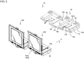
- FIG. 2 is an exploded perspective view of the vehicle lamp 10.
- the lamp unit 20 includes a first bracket 30, an organic EL panel 40, a sub-circuit board 50, and a second bracket 60.
- the organic EL panel 40 is, for example, a glass substrate-type organic EL panel including a front surface 40a, a rear surface 40b on an opposite side to the front surface 40a, and a glass plate (not illustrated) covering at least the front surface 40a.
- the organic EL panel 40 may be a flexible organic EL panel which does not include a glass plate and which has flexibility.
- the front surface 40a of the organic EL panel 40 includes a light-emitting surface 40a1 which emits red light and a non-light emitting area 40a2 which encloses the light-emitting surface 40a1.
- An electrode for supplying power to drive the organic EL panel 40 is provided in the non-light emitting area 40a2.
- a feeder cable 42 is electrically connected to the electrode.
- the non-light emitting area 40a2 may enclose an entire circumference of the light-emitting surface 40a1 or may enclose a part of the light-emitting surface 40a 1.
- the first bracket 30 is arranged on a side of the rear surface 40b of the organic EL panel 40.
- the first bracket 30 is a member with an L-shaped cross section on an XZ plane and includes a first holding section (hereinafter, referred to as an organic EL panel holding section 32) which constitutes a vertical portion of the L shape and a second holding section (hereinafter, referred to as a substrate holding section 34) which constitutes a horizontal portion of the L shape.
- the organic EL panel holding section 32 extends in the Z direction and the substrate holding section 34 extends in the X direction, dimensions in a vertical direction (Z direction) of the first bracket 30 and the vehicle lamp 10 using the first bracket 30 can be reduced.
- the organic EL panel holding section 32 is a rectangular plate-like part including a front surface 32a, and a rear surface 32b on an opposite side to the front surface 32a, and is arranged parallel to the YZ plane.
- the front surface 32a of the organic EL panel holding section 32 includes a rectangular area 32a1 in which the organic EL panel 40 is arranged and a protrusion 32a2 provided so as to enclose the organic EL panel 40 arranged in the rectangular area 32a1.
- the protrusion 32a2 restricts a movement of the organic EL panel 40 in up-down and left-right directions with respect to the first bracket 30 and the second bracket 60.
- the protrusion 32a2 is provided with a notched part 32a3 in which a feeder cable 42 of the organic EL panel 40 is arranged.
- the organic EL panel holding section 32 is provided with a claw part 32c with which a hook part 66 provided in the second bracket 60 engages.
- the claw part 32c is respectively provided in an upper end part of the organic EL panel holding section 32 (one location: refer to FIGS. 3 and 4 ) and in a lower end part of the organic EL panel holding section 32 (two locations: refer to FIG. 4 ).
- a substrate housing section 36 is provided on the lower surface 34b of the substrate holding section 34.
- the substrate housing section 36 includes a substrate housing space S1.
- the substrate housing space S1 is a space enclosed by an upper surface part 36b and a lower surface part 36c arranged parallel to the XY plane, side surface parts 36d arranged parallel to the XZ plane, and a rear surface part 36e arranged parallel to the YZ plane, and an opening 36a communicated with the space is provided on a front side.
- a connector 52 into which a plug 44 provided in the feeder cable 42 of the organic EL panel 40 is inserted, a first electrode 54, and a resistor (not illustrated) to which the connector 52 (the organic EL panel 40) and the first electrode 54 are electrically connected are mounted on the sub-circuit board 50.
- the organic EL panel 40 does not always emit light at a constant brightness even if constant power is supplied thereto.
- the sub-circuit board 50 is mounted with a resistor with a resistance value designed so that the organic EL panel 40 emits light at a constant brightness when constant power is supplied thereto. Accordingly, the organic EL panel 40 can be caused to emit light at a constant brightness.
- the sub-circuit board 50 is inserted into the substrate housing section 36 (the substrate housing space S1) via the opening 36a provided on the front side and, as illustrated in FIGS. 5A and 5B , housed in the substrate housing section 36 (the substrate housing space S1) in a state where the first electrode 54 is exposed from a notched part 36c1 provided in the lower surface part 36c of the substrate housing section 36.
- the sub-circuit board 50 is fixed to (held by) the substrate holding section 34 (the substrate housing section 36) as a front-side end part of the sub-circuit board 50 is pressed by a substrate pressing section 64 provided in the second bracket 60.
- a guide section 38 is respectively provided on both sides in the Y direction of the lower surface 34b of the substrate holding section 34 and the substrate housing section 36.
- the guide section 38 includes a first guide section 38a extending in the X direction and a second guide section 38b extending inward (Y direction) from a tip part (an upper end part in FIG. 4 ) of the first guide section 38a.
- a space S2 into which a second flange part 74b (refer to FIG. 7 ) provided in the housing 70 is inserted is formed between the first guide section 38a and the side surface part 36d of the substrate housing section 36.
- a space S3 into which a first flange part 74a (refer to FIG. 7 ) provided in the housing 70 is inserted is formed between the second guide section 38b and the side surface part 36d of the substrate housing section 36.
- the substrate holding section 34 is provided with a claw part 34c with which a hook part 78 (refer to FIG. 7 ) provided in the housing 70 engages.
- the claw part 34c is provided on, for example, an upper surface (two locations) of the substrate holding section 34.
- the first bracket 30 in the configuration described above can be formed by injection molding of a transparent resin such as acrylic or polycarbonate.
- the second bracket 60 is arranged on a side of the front surface 40a of the organic EL panel 40.
- the second bracket 60 includes a transparent plate 62, the substrate pressing section 64, and the hook part 66.
- the transparent plate 62 is a rectangular plate-like transparent plate through which light emitted by the light-emitting surface 40a1 of the organic EL panel 40 passes and is arranged parallel to the YZ plane.
- a size of the transparent plate 62 is the same (or approximately the same) as that of the light-emitting surface 40a1 of the organic EL panel 40.
- a transparent plate equipped with a function for filtering out UV rays passing through the transparent plate 62 such as a transparent plate molded using acrylic, polycarbonate, or other synthetic resins with a UV-filtering function or a transparent plate to which a UV coating or a UV protection film has been applied is desirably used. Accordingly, resistance to ultraviolet radiation (UV resistance) of the organic EL panel can be improved.
- the transparent plate 62 is provided with the substrate pressing section 64 for pressing a front-side end part of the sub-circuit board 50 housed in the substrate housing section 36 (the substrate housing space S1).
- the substrate pressing section 64 is provided in, for example, a lower end part (two locations) of the transparent plate 62.
- the transparent plate 62 is provided with the hook part 66 with which the claw part 32c provided in the first bracket 30 (the organic EL panel holding section 32) engages.
- the hook part 66 is respectively provided in, for example, an upper end part (one location) of the transparent plate 62 and a lower end part (two locations) of the transparent plate 62.
- the first bracket 30 and the second bracket 60 can be fixed in a state where the organic EL panel 40 is sandwiched between the first bracket 30 and the second bracket 60 as illustrated in FIG. 6 . Accordingly, the organic EL panel 40 can be held in a protected state.
- the plurality of claw parts 32c and the plurality of hook parts 66 represent an example of the second fixing means according to the present invention.
- the hook part 66 provided in the upper end part of the transparent plate 62 is arranged on the rear surface of the first bracket 30 (the organic EL panel holding section 32) (refer to FIG. 5B ), the hook part 66 provided in the upper end part of the transparent plate 62 is prevented from being visible from the front.
- the organic EL panel 40 and the sub-circuit board 50 can be fixed (sandwiched) at the same time.
- FIG. 7 is a perspective view of a housing.
- the housing 70 includes a substrate housing space S4.
- the substrate housing space S4 is a space enclosed by an upper surface part 72b and a lower surface part 72c arranged parallel to the XY plane, side surface parts 72d arranged parallel to the XZ plane, and a rear surface part 72e (refer to FIG. 6 ) arranged parallel to the YZ plane, and an opening 72a communicated with the space is provided on a front side.
- the main circuit board 80 is inserted into the substrate housing space S4 via the opening 72a provided on the front side and, as illustrated in FIG. 2 , housed in the substrate housing space S4 in a state where the second electrode 82 protrudes from an opening 72b1 provided in the upper surface part 72b of the housing 70.
- the main circuit board 80 is fixed to (held by) the housing 70 (the substrate housing space S4) due to the second electrode 82 protruding from the opening 72b1.
- the main circuit board 80 supplies constant power to the sub-circuit board 50 via the second electrode 82 and the first electrode 54 electrically connected to the second electrode 82.
- the main circuit board 80 adjusts power supplied from a power supply (not illustrated) to constant power in accordance with the number of lamp units 20 or a lighting pattern thereof, and supplies the adjusted constant power to the sub-circuit board 50 via the second electrode 82 and the first electrode 54 electrically connected to the second electrode 82.
- the main circuit board 80 (the second electrode 82) functions as the power feeding section.
- the flange part 74 includes a first flange part 74a extending in the X direction and a second flange part 74b extending outward (Y direction) from a tip part (an upper end part in FIG. 7 ) of the first flange part 74a.
- the first flange part 74a is inserted into the space S3 (refer to FIG. 3 ) formed between the second guide section 38b of the first bracket 30 and the side surface part 36d of the substrate housing section 36.
- the second flange part 74b is inserted into the space S2 (refer to FIG. 4 ) formed between the first guide section 38a of the first bracket 30 and the side surface part 36d of the substrate housing section 36.
- a wall part 76 with which the lamp unit 20 (the first bracket 30) comes into contact is provided in the upper surface part 72b of the housing 70.
- the wall part 76 is provided with the hook part 78 with which the claw part 34c provided in the first bracket 30 engages.
- the hook part 78 is provided at, for example, two locations of the wall part 76.
- the housing 70 in the configuration described above can be formed by injection molding using a transparent resin such as acrylic or polycarbonate.
- the lamp unit 20 is mounted to the housing 70 as described below.
- the lamp unit 20 is moved in a direction of an arrow F illustrated in FIG. 2 to insert the flange parts 74 (the first flange part 74a and the second flange part 74b) provided in the housing 70 into the spaces S2 and S3 (refer to FIG. 4 ) between the guide section 38 and the side surface part 36d of the substrate housing section 36 provided in the lamp unit 20.
- the organic EL panel 40 (the first electrode 54) and the second electrode 82 (the power feeding section) can be electrically connected by simply (at the same time as) fixing the lamp unit 20 (the organic EL panel 40) to the housing 70 without having to perform work for connecting the organic EL panel 40 (the first electrode 54) and the second electrode 82 (the power feeding section).
- the lamp unit 20 can be detached from the housing 70 by releasing the engagement of the plurality of hook parts 78 with respect to the plurality of claw parts 34c and reversing the procedure described above.
- the failed lamp unit 20 can be readily detached from the housing 70.
- an unfailed lamp unit 20 can be readily mounted to the housing 70 in place of the failed lamp unit 20.
- the vehicle lamp 10 which enables work for connecting the organic EL panel 40 (the first electrode 54) and the second electrode 82 (the power feeding section) of the main circuit board 80 to be omitted can be provided.
- the housing 70 since the housing 70 includes the second electrode 82 to which the first electrode 54 of the lamp unit 20 fixed to the housing 70 is to be electrically connected, the organic EL panel 40 (the first electrode 54) and the second electrode 82 (the power feeding section) can be electrically connected by simply (at the same time as) fixing the lamp unit 20 (the organic EL panel 40) to the housing 70 without having to perform work for connecting the organic EL panel 40 (the first electrode 54) and the second electrode 82 (the power feeding section).
- the failed lamp unit 20 when a given lamp unit 20 fails, the failed lamp unit 20 can be detached from the housing 70 and an unfailed lamp unit 20 can be mounted to the housing 70. In other words, the lamp unit 20 can be partially replaced.
- the vehicle lamp according to the present invention is not limited to a tail lamp.
- the vehicle lamp according to the present invention may also be applied to position lamps other than a tail lamp, a stop lamp, a turn signal, a side marker lamp, and a vehicle front lamp.
- a rear combination lamp including a tail lamp, a stop lamp, and a turn signal can be constructed by applying the vehicle lamp according to the present invention.
- a screw or other fixing means may be used as the first fixing means which fixes the lamp unit 20 and the housing 70.
- the plurality of claw parts 34c are provided in the lamp unit 20 and the plurality of hook parts 78 are provided in the housing 70
- this configuration is not restrictive.
- the plurality of claw parts 34c may be provided in the housing 70 and the plurality of hook parts 78 may be provided in the lamp unit 20.
- the second fixing means is not limited thereto.
- a screw, an adhesive, or other fixing means may be used as the second fixing means which fixes the first bracket 30 and the second bracket 60.
- the plurality of claw parts 32c are provided in the first bracket 30 and the plurality of hook parts 66 are provided in the second bracket 60
- this configuration is not restrictive.
- the plurality of claw parts 32c may be provided in the second bracket 60 and the plurality of hook parts 66 may be provided in the first bracket 30.
- both the organic EL panel holding section 32 and the substrate holding section 34 may be arranged parallel to the YZ plane.
- the guide section 38 (refer to FIG. 4 ) is provided in the lamp unit 20 and the flange part 74 (refer to FIG. 7 ) is provided in the housing 70 has been described in the embodiment presented above, this configuration is not restrictive.
- the guide section 38 may be provided in the housing 70 and the flange part 74 may be provided in the lamp unit 20.
- a resistor may be provided on the main circuit board 80 or between the sub-circuit board 50 and the main circuit board 80.
- a planar wiring pattern is used as the first electrode 54 of the sub-circuit board 50 and a spring electrode is used as the second electrode 82 of the main circuit board 80
- this configuration is not restrictive.
- a spring electrode may be used as the first electrode 54 of the sub-circuit board 50 and a planar wiring pattern may be used as the second electrode 82 of the main circuit board 80.
Landscapes
- Engineering & Computer Science (AREA)
- General Engineering & Computer Science (AREA)
- Physics & Mathematics (AREA)
- Optics & Photonics (AREA)
- Microelectronics & Electronic Packaging (AREA)
- Non-Portable Lighting Devices Or Systems Thereof (AREA)
- Electroluminescent Light Sources (AREA)
Abstract
Description
- The present invention relates to a vehicle lamp and, in particular, to a vehicle lamp using an organic EL panel.
- Conventionally, vehicle lamps using an organic EL panel including a front surface with a light-emitting surface, and a rear surface on an opposite side to the front surface are proposed (for example, refer to European Patent Application Publication No.
2886936 (Specification)). - However, with the vehicle lamp described in European Patent No.
2886936 , there is a problem that work for connecting an organic EL panel and a power feeding section using, for example, a connector or a feeder cable needs to be performed, resulting in an increase in assembly man-hours which may cause cost to increase. - The present invention has been made in consideration of the circumstances described above and an object thereof is to provide a vehicle lamp which enables work for connecting an organic EL panel and a power feeding section to be omitted.
- In order to achieve the object described above, an aspect of the present invention is a vehicle lamp including: a lamp unit; a mounting section to which the lamp unit is detachably mounted; and first fixing means (a first fixing section) which fixes the lamp unit detachably mounted to the mounting section, and the mounting section, wherein the lamp unit includes: an organic EL panel including a front surface with a light-emitting surface, and a rear surface on an opposite side to the front surface; a first electrode electrically connected to the organic EL panel; and a first bracket which holds the organic EL panel and the first electrode, and the mounting section includes a second electrode to which the first electrode of the lamp unit fixed by the first fixing means (first fixing section) is to be electrically connected.
- According to this aspect, a vehicle lamp which enables work for connecting an organic EL panel and a power feeding section to be omitted can be provided.
- This is attributable to the fact that, since the mounting section includes the second electrode to which the first electrode of the lamp unit fixed to the mounting section is to be electrically connected, the organic EL panel (the first electrode) and the second electrode (the power feeding section) can be electrically connected by simply (at the same time as) fixing the lamp unit (the organic EL panel) to the mounting section without having to perform work for connecting the organic EL panel (the first electrode) and the second electrode (the power feeding section).
- In addition, in a preferred aspect of the invention described above, the lamp unit further includes a resistor to which the organic EL panel and the first electrode are electrically connected, and a substrate on which the first electrode is mounted, and the first bracket includes a first holding section which holds the organic EL panel, and a second holding section which holds the substrate.
- According to this aspect, the organic EL panel can be caused to emit light at a constant brightness.
- Furthermore, a preferred aspect of the invention described above includes the first bracket arranged on the rear surface of the organic EL panel, a second bracket arranged on the front surface of the organic EL panel, and second fixing means (a second fixing section) which fixes the first bracket and the second bracket in a state where the organic EL panel is sandwiched between the first bracket and the second bracket.
- According to this aspect, the organic EL panel can be held in a protected state.
- In addition, in a preferred aspect of the invention described above, the first holding section extends in a first direction, and the second holding section extends in a second direction which intersects with the first direction.
- According to this aspect, dimensions in the first direction of the first bracket and the vehicle lamp using the first bracket can be reduced.
- Furthermore, in a preferred aspect of the invention described above, the second holding section is provided with a substrate housing section which houses the substrate, and the second bracket is provided with a substrate pressing section which presses the substrate housed in the substrate housing section in a state where the first bracket and the second bracket are fixed by the second fixing means (second fixing section).
- According to this aspect, by fixing the first bracket and the second bracket, the organic EL panel and the substrate can be fixed at the same time.
-
-
FIG. 1 is a perspective view of avehicle lamp 10; -
FIG. 2 is an exploded perspective view of thevehicle lamp 10; -
FIG. 3 is an exploded perspective view of alamp unit 20; -
FIG. 4 is an exploded perspective view of thelamp unit 20; -
FIGS. 5A and 5B are perspective views of thelamp unit 20; -
FIG. 6 is a sectional view taken along A-A inFIG. 1 ; -
FIG. 7 is a perspective view of a housing; and -
FIG. 8 is a perspective view of the vehicle lamp 10 (modification). - Hereinafter, a
vehicle lamp 10 representing a first embodiment of the present invention will be described with reference to the accompanying drawings. Corresponding components in the respective drawings will be denoted by same reference signs and redundant descriptions thereof will be omitted. -
FIG. 1 is a perspective view of thevehicle lamp 10. - The
vehicle lamp 10 illustrated inFIG. 1 is, for example, a tail lamp mounted on left and right sides of a rear end part of a vehicle (not illustrated). X, Y, and Z axes will now be defined for the sake of convenience. The X axis extends in a front-back direction of the vehicle, the Y axis extends in a width direction of the vehicle, and the Z axis extends in a vertical direction. -
FIG. 2 is an exploded perspective view of thevehicle lamp 10. - As illustrated in
FIG. 2 , thevehicle lamp 10 according to the present embodiment includeslamp units housing 70. Thehousing 70 represents an example of the mounting section according to the present invention. Since thelamp units lamp unit 20" will be used unless there is a need to distinguish thelamp units lamp units 20 is not particularly limited and only one or three ormore lamp units 20 may be provided. -
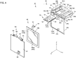
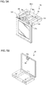
FIGS. 3 and4 are exploded perspective views of thelamp unit 20.FIGS. 5 are perspective views of thelamp unit 20.FIG. 6 is a sectional view taken along A-A inFIG. 1 . - As illustrated in
FIGS. 3 and4 , thelamp unit 20 includes afirst bracket 30, anorganic EL panel 40, asub-circuit board 50, and asecond bracket 60. - The
organic EL panel 40 is, for example, a glass substrate-type organic EL panel including afront surface 40a, arear surface 40b on an opposite side to thefront surface 40a, and a glass plate (not illustrated) covering at least thefront surface 40a. Alternatively, theorganic EL panel 40 may be a flexible organic EL panel which does not include a glass plate and which has flexibility. - The
front surface 40a of theorganic EL panel 40 includes a light-emitting surface 40a1 which emits red light and a non-light emitting area 40a2 which encloses the light-emitting surface 40a1. An electrode for supplying power to drive theorganic EL panel 40 is provided in the non-light emitting area 40a2. Afeeder cable 42 is electrically connected to the electrode. Moreover, the non-light emitting area 40a2 may enclose an entire circumference of the light-emitting surface 40a1 or may enclose a part of the light-emittingsurface 40a 1. - The
first bracket 30 is arranged on a side of therear surface 40b of theorganic EL panel 40. Thefirst bracket 30 is a member with an L-shaped cross section on an XZ plane and includes a first holding section (hereinafter, referred to as an organic EL panel holding section 32) which constitutes a vertical portion of the L shape and a second holding section (hereinafter, referred to as a substrate holding section 34) which constitutes a horizontal portion of the L shape. - As described above, since the organic EL
panel holding section 32 extends in the Z direction and thesubstrate holding section 34 extends in the X direction, dimensions in a vertical direction (Z direction) of thefirst bracket 30 and thevehicle lamp 10 using thefirst bracket 30 can be reduced. - The organic EL
panel holding section 32 is a rectangular plate-like part including afront surface 32a, and arear surface 32b on an opposite side to thefront surface 32a, and is arranged parallel to the YZ plane. - The
front surface 32a of the organic ELpanel holding section 32 includes a rectangular area 32a1 in which theorganic EL panel 40 is arranged and a protrusion 32a2 provided so as to enclose theorganic EL panel 40 arranged in the rectangular area 32a1. The protrusion 32a2 restricts a movement of theorganic EL panel 40 in up-down and left-right directions with respect to thefirst bracket 30 and thesecond bracket 60. - The protrusion 32a2 is provided with a notched part 32a3 in which a
feeder cable 42 of theorganic EL panel 40 is arranged. - In order to fix the
second bracket 60 to thefirst bracket 30, the organic ELpanel holding section 32 is provided with aclaw part 32c with which ahook part 66 provided in thesecond bracket 60 engages. Theclaw part 32c is respectively provided in an upper end part of the organic EL panel holding section 32 (one location: refer toFIGS. 3 and4 ) and in a lower end part of the organic EL panel holding section 32 (two locations: refer toFIG. 4 ). - The
substrate holding section 34 is a rectangular plate-like part including anupper surface 34a (refer toFIG. 3 ) and alower surface 34b (refer toFIG. 4 ) on an opposite side to theupper surface 34a and is arranged parallel to the XY plane. A front-side end part of thesubstrate holding section 34 is coupled to a lower end part of the organic ELpanel holding section 32. - As illustrated in
FIG. 4 , asubstrate housing section 36 is provided on thelower surface 34b of thesubstrate holding section 34. - The
substrate housing section 36 includes a substrate housing space S1. The substrate housing space S1 is a space enclosed by anupper surface part 36b and alower surface part 36c arranged parallel to the XY plane,side surface parts 36d arranged parallel to the XZ plane, and arear surface part 36e arranged parallel to the YZ plane, and an opening 36a communicated with the space is provided on a front side. - A
connector 52 into which aplug 44 provided in thefeeder cable 42 of theorganic EL panel 40 is inserted, afirst electrode 54, and a resistor (not illustrated) to which the connector 52 (the organic EL panel 40) and thefirst electrode 54 are electrically connected are mounted on thesub-circuit board 50. - Next, a technical significance of the resistor mounted on the
sub-circuit board 50 will be described. - In the
vehicle lamp 10, theorganic EL panel 40 is needed to emit light at a constant brightness (luminance). - However, due to manufacturing variability, the
organic EL panel 40 does not always emit light at a constant brightness even if constant power is supplied thereto. - In consideration thereof, the
sub-circuit board 50 is mounted with a resistor with a resistance value designed so that theorganic EL panel 40 emits light at a constant brightness when constant power is supplied thereto. Accordingly, theorganic EL panel 40 can be caused to emit light at a constant brightness. - The
sub-circuit board 50 is inserted into the substrate housing section 36 (the substrate housing space S1) via theopening 36a provided on the front side and, as illustrated inFIGS. 5A and 5B , housed in the substrate housing section 36 (the substrate housing space S1) in a state where thefirst electrode 54 is exposed from a notched part 36c1 provided in thelower surface part 36c of thesubstrate housing section 36. - In addition, as illustrated in
FIG. 6 , thesub-circuit board 50 is fixed to (held by) the substrate holding section 34 (the substrate housing section 36) as a front-side end part of thesub-circuit board 50 is pressed by asubstrate pressing section 64 provided in thesecond bracket 60. - As illustrated in
FIG. 4 , aguide section 38 is respectively provided on both sides in the Y direction of thelower surface 34b of thesubstrate holding section 34 and thesubstrate housing section 36. - The
guide section 38 includes afirst guide section 38a extending in the X direction and asecond guide section 38b extending inward (Y direction) from a tip part (an upper end part inFIG. 4 ) of thefirst guide section 38a. - A space S2 into which a
second flange part 74b (refer toFIG. 7 ) provided in thehousing 70 is inserted is formed between thefirst guide section 38a and theside surface part 36d of thesubstrate housing section 36. - A space S3 into which a
first flange part 74a (refer toFIG. 7 ) provided in thehousing 70 is inserted is formed between thesecond guide section 38b and theside surface part 36d of thesubstrate housing section 36. - As illustrated in
FIG. 3 , in order to fix thelamp unit 20 to thehousing 70, thesubstrate holding section 34 is provided with aclaw part 34c with which a hook part 78 (refer toFIG. 7 ) provided in thehousing 70 engages. Theclaw part 34c is provided on, for example, an upper surface (two locations) of thesubstrate holding section 34. - The
first bracket 30 in the configuration described above can be formed by injection molding of a transparent resin such as acrylic or polycarbonate. - As illustrated in
FIGS. 3 and4 , thesecond bracket 60 is arranged on a side of thefront surface 40a of theorganic EL panel 40. - The
second bracket 60 includes atransparent plate 62, thesubstrate pressing section 64, and thehook part 66. - The
transparent plate 62 is a rectangular plate-like transparent plate through which light emitted by the light-emitting surface 40a1 of theorganic EL panel 40 passes and is arranged parallel to the YZ plane. A size of thetransparent plate 62 is the same (or approximately the same) as that of the light-emitting surface 40a1 of theorganic EL panel 40. As thetransparent plate 62, a transparent plate equipped with a function for filtering out UV rays passing through thetransparent plate 62 such as a transparent plate molded using acrylic, polycarbonate, or other synthetic resins with a UV-filtering function or a transparent plate to which a UV coating or a UV protection film has been applied is desirably used. Accordingly, resistance to ultraviolet radiation (UV resistance) of the organic EL panel can be improved. - The
transparent plate 62 is provided with thesubstrate pressing section 64 for pressing a front-side end part of thesub-circuit board 50 housed in the substrate housing section 36 (the substrate housing space S1). Thesubstrate pressing section 64 is provided in, for example, a lower end part (two locations) of thetransparent plate 62. - In order to fix the
second bracket 60 to thefirst bracket 30, thetransparent plate 62 is provided with thehook part 66 with which theclaw part 32c provided in the first bracket 30 (the organic EL panel holding section 32) engages. Thehook part 66 is respectively provided in, for example, an upper end part (one location) of thetransparent plate 62 and a lower end part (two locations) of thetransparent plate 62. - By causing the plurality of
hook parts 66 provided on thetransparent plate 62 to engage with the plurality ofclaw parts 32c provided in thefirst bracket 30 as illustrated inFIGS. 5A and 5B , thefirst bracket 30 and thesecond bracket 60 can be fixed in a state where theorganic EL panel 40 is sandwiched between thefirst bracket 30 and thesecond bracket 60 as illustrated inFIG. 6 . Accordingly, theorganic EL panel 40 can be held in a protected state. The plurality ofclaw parts 32c and the plurality ofhook parts 66 represent an example of the second fixing means according to the present invention. - In doing so, since the
hook part 66 provided in the upper end part of thetransparent plate 62 is arranged on the rear surface of the first bracket 30 (the organic EL panel holding section 32) (refer toFIG. 5B ), thehook part 66 provided in the upper end part of thetransparent plate 62 is prevented from being visible from the front. - In addition, by causing the plurality of
hook parts 66 provided on thetransparent plate 62 to engage with the plurality ofclaw parts 32c provided in thefirst bracket 30 as illustrated inFIGS. 5A and 5B , thefirst bracket 30 and thesecond bracket 60 can be fixed in a state where thesub-circuit board 50 is sandwiched between thesubstrate pressing section 64 provided on thetransparent plate 62 and therear surface part 36e of thesubstrate housing section 36 as illustrated inFIG. 6 . - In this manner, by fixing the
first bracket 30 and thesecond bracket 60, theorganic EL panel 40 and thesub-circuit board 50 can be fixed (sandwiched) at the same time. -
FIG. 7 is a perspective view of a housing. - As illustrated in
FIG. 7 , thehousing 70 includes a substrate housing space S4. The substrate housing space S4 is a space enclosed by anupper surface part 72b and alower surface part 72c arranged parallel to the XY plane,side surface parts 72d arranged parallel to the XZ plane, and arear surface part 72e (refer toFIG. 6 ) arranged parallel to the YZ plane, and anopening 72a communicated with the space is provided on a front side. - A
second electrode 82 to be electrically connected to thefirst electrode 54 mounted on thesub-circuit board 50 and the like are mounted on amain circuit board 80. Thesecond electrode 82 is a spring electrode. Thesecond electrode 82 may be an arch-type spring electrode, a leaf spring-type spring electrode, or other spring electrodes. - The
main circuit board 80 is inserted into the substrate housing space S4 via theopening 72a provided on the front side and, as illustrated inFIG. 2 , housed in the substrate housing space S4 in a state where thesecond electrode 82 protrudes from an opening 72b1 provided in theupper surface part 72b of thehousing 70. - The
main circuit board 80 is fixed to (held by) the housing 70 (the substrate housing space S4) due to thesecond electrode 82 protruding from the opening 72b1. - The
main circuit board 80 supplies constant power to thesub-circuit board 50 via thesecond electrode 82 and thefirst electrode 54 electrically connected to thesecond electrode 82. For example, themain circuit board 80 adjusts power supplied from a power supply (not illustrated) to constant power in accordance with the number oflamp units 20 or a lighting pattern thereof, and supplies the adjusted constant power to thesub-circuit board 50 via thesecond electrode 82 and thefirst electrode 54 electrically connected to thesecond electrode 82. In this case, the main circuit board 80 (the second electrode 82) functions as the power feeding section. - As illustrated in
FIG. 7 , aflange part 74 is respectively provided on both sides in the Y direction of an upper surface and the opening 72b1 of theupper surface part 72b of thehousing 70. - The
flange part 74 includes afirst flange part 74a extending in the X direction and asecond flange part 74b extending outward (Y direction) from a tip part (an upper end part inFIG. 7 ) of thefirst flange part 74a. - The
first flange part 74a is inserted into the space S3 (refer toFIG. 3 ) formed between thesecond guide section 38b of thefirst bracket 30 and theside surface part 36d of thesubstrate housing section 36. - The
second flange part 74b is inserted into the space S2 (refer toFIG. 4 ) formed between thefirst guide section 38a of thefirst bracket 30 and theside surface part 36d of thesubstrate housing section 36. - In addition, a
wall part 76 with which the lamp unit 20 (the first bracket 30) comes into contact is provided in theupper surface part 72b of thehousing 70. In order to fix thelamp unit 20 to thehousing 70, thewall part 76 is provided with thehook part 78 with which theclaw part 34c provided in thefirst bracket 30 engages. Thehook part 78 is provided at, for example, two locations of thewall part 76. - The
housing 70 in the configuration described above can be formed by injection molding using a transparent resin such as acrylic or polycarbonate. - The
lamp unit 20 is mounted to thehousing 70 as described below. - First, the
lamp unit 20 is moved in a direction of an arrow F illustrated inFIG. 2 to insert the flange parts 74 (thefirst flange part 74a and thesecond flange part 74b) provided in thehousing 70 into the spaces S2 and S3 (refer toFIG. 4 ) between theguide section 38 and theside surface part 36d of thesubstrate housing section 36 provided in thelamp unit 20. - Next, the
lamp unit 20 is moved (slidingly moved) in the direction of the arrow F along the guide sections 38 (thefirst guide section 38a and thesecond guide section 38b) until the lamp unit 20 (the substrate holding section 34) comes into contact with thewall part 76 provided in the housing 70 (refer toFIG. 6 ) to cause the plurality ofhook parts 78 provided in thehousing 70 to engage with the plurality ofclaw parts 34c provided in thelamp unit 20. Accordingly, thelamp unit 20 is positioned with respect to thehousing 70 and, at the same time, fixed to thehousing 70 in a state where thefirst electrode 54 and thesecond electrode 82 are electrically connected (FIG. 6 ). The plurality ofclaw parts 34c and the plurality ofhook parts 78 represent an example of the first fixing means according to the present invention. - In this manner, the organic EL panel 40 (the first electrode 54) and the second electrode 82 (the power feeding section) can be electrically connected by simply (at the same time as) fixing the lamp unit 20 (the organic EL panel 40) to the
housing 70 without having to perform work for connecting the organic EL panel 40 (the first electrode 54) and the second electrode 82 (the power feeding section). - The
lamp unit 20 can be detached from thehousing 70 by releasing the engagement of the plurality ofhook parts 78 with respect to the plurality ofclaw parts 34c and reversing the procedure described above. - Therefore, for example, when the
lamp unit 20 fails, the failedlamp unit 20 can be readily detached from thehousing 70. In addition, anunfailed lamp unit 20 can be readily mounted to thehousing 70 in place of the failedlamp unit 20. - As described above, according to the present embodiment, the
vehicle lamp 10 which enables work for connecting the organic EL panel 40 (the first electrode 54) and the second electrode 82 (the power feeding section) of themain circuit board 80 to be omitted can be provided. - This is attributable to the fact that, since the
housing 70 includes thesecond electrode 82 to which thefirst electrode 54 of thelamp unit 20 fixed to thehousing 70 is to be electrically connected, the organic EL panel 40 (the first electrode 54) and the second electrode 82 (the power feeding section) can be electrically connected by simply (at the same time as) fixing the lamp unit 20 (the organic EL panel 40) to thehousing 70 without having to perform work for connecting the organic EL panel 40 (the first electrode 54) and the second electrode 82 (the power feeding section). - In addition, according to the present embodiment, when a given
lamp unit 20 fails, the failedlamp unit 20 can be detached from thehousing 70 and anunfailed lamp unit 20 can be mounted to thehousing 70. In other words, thelamp unit 20 can be partially replaced. - Next, modifications will be described.
- While an example in which the vehicle lamp according to the present invention is applied to a tail lamp has been described in the embodiment presented above, the vehicle lamp is not limited to a tail lamp. For example, the vehicle lamp according to the present invention may also be applied to position lamps other than a tail lamp, a stop lamp, a turn signal, a side marker lamp, and a vehicle front lamp. In addition, a rear combination lamp including a tail lamp, a stop lamp, and a turn signal can be constructed by applying the vehicle lamp according to the present invention.
- In addition, while an example in which the plurality of
claw parts 34c and the plurality ofhook parts 78 are used as the first fixing means which fixes thelamp unit 20 and thehousing 70 has been described in the embodiment presented above, the first fixing means is not limited thereto. - For example, a screw or other fixing means may be used as the first fixing means which fixes the
lamp unit 20 and thehousing 70. - Furthermore, while an example in which the plurality of
claw parts 34c are provided in thelamp unit 20 and the plurality ofhook parts 78 are provided in thehousing 70 has been described in the embodiment presented above, this configuration is not restrictive. For example, the plurality ofclaw parts 34c may be provided in thehousing 70 and the plurality ofhook parts 78 may be provided in thelamp unit 20. - In addition, while an example in which the plurality of
claw parts 32c and the plurality ofhook parts 66 are used as the second fixing means which fixes thefirst bracket 30 and thesecond bracket 60 has been described in the embodiment presented above, the second fixing means is not limited thereto. - For example, a screw, an adhesive, or other fixing means may be used as the second fixing means which fixes the
first bracket 30 and thesecond bracket 60. - Furthermore, while an example in which the plurality of
claw parts 32c are provided in thefirst bracket 30 and the plurality ofhook parts 66 are provided in thesecond bracket 60 has been described in the embodiment presented above, this configuration is not restrictive. For example, the plurality ofclaw parts 32c may be provided in thesecond bracket 60 and the plurality ofhook parts 66 may be provided in thefirst bracket 30. - In addition, while an example in which the organic EL
panel holding section 32 is arranged parallel to the YZ plane and thesubstrate holding section 34 is arranged parallel to the XY plane has been described in the embodiment presented above, arrangements are not limited thereto. - For example, as illustrated in
FIG. 8 , both the organic ELpanel holding section 32 and thesubstrate holding section 34 may be arranged parallel to the YZ plane. - Furthermore, while an example in which the guide section 38 (refer to
FIG. 4 ) is provided in thelamp unit 20 and the flange part 74 (refer toFIG. 7 ) is provided in thehousing 70 has been described in the embodiment presented above, this configuration is not restrictive. For example, theguide section 38 may be provided in thehousing 70 and theflange part 74 may be provided in thelamp unit 20. - In addition, while an example in which a resistor is provided on the
sub-circuit board 50 has been described in the embodiment presented above, this configuration is not restrictive. For example, a resistor may be provided on themain circuit board 80 or between thesub-circuit board 50 and themain circuit board 80. - Furthermore, while an example in which a planar wiring pattern is used as the
first electrode 54 of thesub-circuit board 50 and a spring electrode is used as thesecond electrode 82 of themain circuit board 80 has been described in the embodiment presented above, this configuration is not restrictive. For example, a spring electrode may be used as thefirst electrode 54 of thesub-circuit board 50 and a planar wiring pattern may be used as thesecond electrode 82 of themain circuit board 80. - The respective numerical values presented in the respective embodiments described above are by way of example only and, obviously, different appropriate numerical values can be used.
- The respective embodiments described above are to be considered in all respects as illustrative and not restrictive. The present invention is not to be taken in a limited sense based on the description of the respective embodiments presented above. The present invention may be embodied in various other forms without departing from the spirit or primary characteristics thereof.
Claims (6)
- A vehicle lamp comprising:a lamp unit;a mounting section to which the lamp unit is detachably mounted; andfirst fixing means which fixes the lamp unit detachably mounted to the mounting section, and the mounting section, whereinthe lamp unit includes:an organic EL panel including a front surface with a light-emitting surface, and a rear surface on an opposite side to the front surface;a first electrode electrically connected to the organic EL panel; anda first bracket which holds the organic EL panel and the first electrode, andthe mounting section includes a second electrode to which the first electrode of the lamp unit fixed by the first fixing means is to be electrically connected.
- The vehicle lamp according to claim 1, wherein
the lamp unit further includes a resistor to which the organic EL panel and the first electrode are electrically connected, and a substrate on which the first electrode is mounted, and
the first bracket includes a first holding section which holds the organic EL panel, and a second holding section which holds the substrate. - The vehicle lamp according to claim 2, comprising:the first bracket arranged on the rear surface of the organic EL panel;a second bracket arranged on the front surface of the organic EL panel; andsecond fixing means which fixes the first bracket and the second bracket in a state where the organic EL panel is sandwiched between the first bracket and the second bracket.
- The vehicle lamp according to claim 3, wherein
the first holding section extends in a first direction, and
the second holding section extends in a second direction which intersects with the first direction. - The vehicle lamp according to claim 3, wherein
the second holding section is provided with a substrate housing section which houses the substrate, and
the second bracket is provided with a substrate pressing section which presses the substrate housed in the substrate housing section in a state where the first bracket and the second bracket are fixed by the second fixing means. - The vehicle lamp according to claim 4, wherein
the second holding section is provided with a substrate housing section which houses the substrate, and
the second bracket is provided with a substrate pressing section which presses the substrate housed in the substrate housing section in a state where the first bracket and the second bracket are fixed by the second fixing means.
Applications Claiming Priority (1)
| Application Number | Priority Date | Filing Date | Title |
|---|---|---|---|
| JP2017160186A JP6968619B2 (en) | 2017-08-23 | 2017-08-23 | Vehicle lighting |
Publications (2)
| Publication Number | Publication Date |
|---|---|
| EP3447369A1 true EP3447369A1 (en) | 2019-02-27 |
| EP3447369B1 EP3447369B1 (en) | 2022-01-26 |
Family
ID=63528502
Family Applications (1)
| Application Number | Title | Priority Date | Filing Date |
|---|---|---|---|
| EP18190246.1A Active EP3447369B1 (en) | 2017-08-23 | 2018-08-22 | Vehicle lamp |
Country Status (3)
| Country | Link |
|---|---|
| US (1) | US10663132B2 (en) |
| EP (1) | EP3447369B1 (en) |
| JP (1) | JP6968619B2 (en) |
Cited By (2)
| Publication number | Priority date | Publication date | Assignee | Title |
|---|---|---|---|---|
| WO2021005331A1 (en) * | 2019-07-11 | 2021-01-14 | Dyson Technology Limited | Vehicle lamp assembly |
| WO2021005330A1 (en) * | 2019-07-11 | 2021-01-14 | Dyson Technology Limited | Vehicle lamp assembly |
Families Citing this family (1)
| Publication number | Priority date | Publication date | Assignee | Title |
|---|---|---|---|---|
| JP2022139539A (en) * | 2021-03-12 | 2022-09-26 | 市光工業株式会社 | Light source unit and vehicular lighting fixture |
Citations (6)
| Publication number | Priority date | Publication date | Assignee | Title |
|---|---|---|---|---|
| US20100237774A1 (en) * | 2009-03-18 | 2010-09-23 | Semiconductor Energy Laboratory Co., Ltd. | Lighting Device |
| EP2719946A1 (en) * | 2011-06-07 | 2014-04-16 | Panasonic Corporation | Illumination system |
| EP2886936A1 (en) | 2013-12-23 | 2015-06-24 | odelo GmbH | Lighting device and motor vehicle light equipped with same |
| EP3026761A1 (en) * | 2014-11-27 | 2016-06-01 | odelo GmbH | Direct connection for electrically contacting flexible strip conductor holders in vehicle lights |
| EP3088797A1 (en) * | 2013-12-25 | 2016-11-02 | Koito Manufacturing Co., Ltd. | Vehicle lamp |
| US20170164433A1 (en) * | 2014-02-13 | 2017-06-08 | Kaneka Corporation | Light emission module, connector, and mounting structure for light emission module |
Family Cites Families (3)
| Publication number | Priority date | Publication date | Assignee | Title |
|---|---|---|---|---|
| JP5770046B2 (en) * | 2011-08-22 | 2015-08-26 | 株式会社小糸製作所 | Vehicle lamp equipped with a flat light source |
| JP6383548B2 (en) * | 2014-03-10 | 2018-08-29 | 株式会社小糸製作所 | Lamp |
| JP2016058136A (en) * | 2014-09-05 | 2016-04-21 | 株式会社小糸製作所 | Vehicle lamp and light emitting unit |
-
2017
- 2017-08-23 JP JP2017160186A patent/JP6968619B2/en not_active Expired - Fee Related
-
2018
- 2018-08-21 US US16/107,508 patent/US10663132B2/en active Active
- 2018-08-22 EP EP18190246.1A patent/EP3447369B1/en active Active
Patent Citations (6)
| Publication number | Priority date | Publication date | Assignee | Title |
|---|---|---|---|---|
| US20100237774A1 (en) * | 2009-03-18 | 2010-09-23 | Semiconductor Energy Laboratory Co., Ltd. | Lighting Device |
| EP2719946A1 (en) * | 2011-06-07 | 2014-04-16 | Panasonic Corporation | Illumination system |
| EP2886936A1 (en) | 2013-12-23 | 2015-06-24 | odelo GmbH | Lighting device and motor vehicle light equipped with same |
| EP3088797A1 (en) * | 2013-12-25 | 2016-11-02 | Koito Manufacturing Co., Ltd. | Vehicle lamp |
| US20170164433A1 (en) * | 2014-02-13 | 2017-06-08 | Kaneka Corporation | Light emission module, connector, and mounting structure for light emission module |
| EP3026761A1 (en) * | 2014-11-27 | 2016-06-01 | odelo GmbH | Direct connection for electrically contacting flexible strip conductor holders in vehicle lights |
Cited By (3)
| Publication number | Priority date | Publication date | Assignee | Title |
|---|---|---|---|---|
| WO2021005331A1 (en) * | 2019-07-11 | 2021-01-14 | Dyson Technology Limited | Vehicle lamp assembly |
| WO2021005330A1 (en) * | 2019-07-11 | 2021-01-14 | Dyson Technology Limited | Vehicle lamp assembly |
| US11719410B2 (en) | 2019-07-11 | 2023-08-08 | Dyson Technology Limited | Vehicle lamp assembly |
Also Published As
| Publication number | Publication date |
|---|---|
| JP2019040693A (en) | 2019-03-14 |
| EP3447369B1 (en) | 2022-01-26 |
| US20190063705A1 (en) | 2019-02-28 |
| US10663132B2 (en) | 2020-05-26 |
| JP6968619B2 (en) | 2021-11-17 |
Similar Documents
| Publication | Publication Date | Title |
|---|---|---|
| US9028089B2 (en) | Illumination device and illumination system | |
| US20080198606A1 (en) | Panel mount light emitting element assembly | |
| EP3447369B1 (en) | Vehicle lamp | |
| EP2277741B1 (en) | Light guide turn signal indicator rear view mirror | |
| US9511707B2 (en) | Vehicular lamp | |
| US9688182B2 (en) | Vehicle lamp | |
| CN107013814B (en) | LED signal module | |
| JP6409330B2 (en) | Vehicle lighting | |
| JP6313563B2 (en) | Vehicle lamp | |
| JP2020145120A (en) | Vehicle lighting | |
| CN110131669B (en) | Lighting and/or luminous signalling device for a motor vehicle | |
| US9487133B2 (en) | Turn lamp for door mirror | |
| JP5288096B2 (en) | Display device | |
| EP3339092A1 (en) | Vehicular lamp | |
| JP6818504B2 (en) | Vehicle lighting | |
| JP7205733B2 (en) | lighting equipment | |
| CN113631858B (en) | Vehicle lamps | |
| KR200493649Y1 (en) | Connector for bar type LED lamp connection | |
| WO2013108666A1 (en) | Light fixture for vehicle | |
| JP6671443B2 (en) | Vehicle lighting | |
| CN213637984U (en) | Display devices and televisions | |
| JP2015191820A (en) | Light-emitting module, and mounting structure of light-emitting module | |
| JP7491754B2 (en) | Vehicle Lighting | |
| US10488009B2 (en) | Motor vehicle lamp | |
| US11505115B2 (en) | Lighting device for a motor vehicle |
Legal Events
| Date | Code | Title | Description |
|---|---|---|---|
| PUAI | Public reference made under article 153(3) epc to a published international application that has entered the european phase |
Free format text: ORIGINAL CODE: 0009012 |
|
| STAA | Information on the status of an ep patent application or granted ep patent |
Free format text: STATUS: THE APPLICATION HAS BEEN PUBLISHED |
|
| AK | Designated contracting states |
Kind code of ref document: A1 Designated state(s): AL AT BE BG CH CY CZ DE DK EE ES FI FR GB GR HR HU IE IS IT LI LT LU LV MC MK MT NL NO PL PT RO RS SE SI SK SM TR |
|
| AX | Request for extension of the european patent |
Extension state: BA ME |
|
| STAA | Information on the status of an ep patent application or granted ep patent |
Free format text: STATUS: REQUEST FOR EXAMINATION WAS MADE |
|
| 17P | Request for examination filed |
Effective date: 20190827 |
|
| RBV | Designated contracting states (corrected) |
Designated state(s): AL AT BE BG CH CY CZ DE DK EE ES FI FR GB GR HR HU IE IS IT LI LT LU LV MC MK MT NL NO PL PT RO RS SE SI SK SM TR |
|
| RIC1 | Information provided on ipc code assigned before grant |
Ipc: F21S 41/155 20180101AFI20210728BHEP Ipc: F21S 41/19 20180101ALI20210728BHEP Ipc: F21S 43/145 20180101ALI20210728BHEP Ipc: F21S 43/19 20180101ALI20210728BHEP Ipc: F21Y 115/15 20160101ALN20210728BHEP |
|
| GRAP | Despatch of communication of intention to grant a patent |
Free format text: ORIGINAL CODE: EPIDOSNIGR1 |
|
| STAA | Information on the status of an ep patent application or granted ep patent |
Free format text: STATUS: GRANT OF PATENT IS INTENDED |
|
| INTG | Intention to grant announced |
Effective date: 20210907 |
|
| GRAS | Grant fee paid |
Free format text: ORIGINAL CODE: EPIDOSNIGR3 |
|
| GRAA | (expected) grant |
Free format text: ORIGINAL CODE: 0009210 |
|
| STAA | Information on the status of an ep patent application or granted ep patent |
Free format text: STATUS: THE PATENT HAS BEEN GRANTED |
|
| AK | Designated contracting states |
Kind code of ref document: B1 Designated state(s): AL AT BE BG CH CY CZ DE DK EE ES FI FR GB GR HR HU IE IS IT LI LT LU LV MC MK MT NL NO PL PT RO RS SE SI SK SM TR |
|
| REG | Reference to a national code |
Ref country code: GB Ref legal event code: FG4D |
|
| REG | Reference to a national code |
Ref country code: CH Ref legal event code: EP |
|
| REG | Reference to a national code |
Ref country code: AT Ref legal event code: REF Ref document number: 1465542 Country of ref document: AT Kind code of ref document: T Effective date: 20220215 |
|
| REG | Reference to a national code |
Ref country code: IE Ref legal event code: FG4D |
|
| REG | Reference to a national code |
Ref country code: DE Ref legal event code: R096 Ref document number: 602018029977 Country of ref document: DE |
|
| REG | Reference to a national code |
Ref country code: LT Ref legal event code: MG9D |
|
| REG | Reference to a national code |
Ref country code: NL Ref legal event code: MP Effective date: 20220126 |
|
| REG | Reference to a national code |
Ref country code: AT Ref legal event code: MK05 Ref document number: 1465542 Country of ref document: AT Kind code of ref document: T Effective date: 20220126 |
|
| PG25 | Lapsed in a contracting state [announced via postgrant information from national office to epo] |
Ref country code: NL Free format text: LAPSE BECAUSE OF FAILURE TO SUBMIT A TRANSLATION OF THE DESCRIPTION OR TO PAY THE FEE WITHIN THE PRESCRIBED TIME-LIMIT Effective date: 20220126 |
|
| PG25 | Lapsed in a contracting state [announced via postgrant information from national office to epo] |
Ref country code: SE Free format text: LAPSE BECAUSE OF FAILURE TO SUBMIT A TRANSLATION OF THE DESCRIPTION OR TO PAY THE FEE WITHIN THE PRESCRIBED TIME-LIMIT Effective date: 20220126 Ref country code: RS Free format text: LAPSE BECAUSE OF FAILURE TO SUBMIT A TRANSLATION OF THE DESCRIPTION OR TO PAY THE FEE WITHIN THE PRESCRIBED TIME-LIMIT Effective date: 20220126 Ref country code: PT Free format text: LAPSE BECAUSE OF FAILURE TO SUBMIT A TRANSLATION OF THE DESCRIPTION OR TO PAY THE FEE WITHIN THE PRESCRIBED TIME-LIMIT Effective date: 20220526 Ref country code: NO Free format text: LAPSE BECAUSE OF FAILURE TO SUBMIT A TRANSLATION OF THE DESCRIPTION OR TO PAY THE FEE WITHIN THE PRESCRIBED TIME-LIMIT Effective date: 20220426 Ref country code: LT Free format text: LAPSE BECAUSE OF FAILURE TO SUBMIT A TRANSLATION OF THE DESCRIPTION OR TO PAY THE FEE WITHIN THE PRESCRIBED TIME-LIMIT Effective date: 20220126 Ref country code: HR Free format text: LAPSE BECAUSE OF FAILURE TO SUBMIT A TRANSLATION OF THE DESCRIPTION OR TO PAY THE FEE WITHIN THE PRESCRIBED TIME-LIMIT Effective date: 20220126 Ref country code: ES Free format text: LAPSE BECAUSE OF FAILURE TO SUBMIT A TRANSLATION OF THE DESCRIPTION OR TO PAY THE FEE WITHIN THE PRESCRIBED TIME-LIMIT Effective date: 20220126 Ref country code: BG Free format text: LAPSE BECAUSE OF FAILURE TO SUBMIT A TRANSLATION OF THE DESCRIPTION OR TO PAY THE FEE WITHIN THE PRESCRIBED TIME-LIMIT Effective date: 20220426 |
|
| PG25 | Lapsed in a contracting state [announced via postgrant information from national office to epo] |
Ref country code: PL Free format text: LAPSE BECAUSE OF FAILURE TO SUBMIT A TRANSLATION OF THE DESCRIPTION OR TO PAY THE FEE WITHIN THE PRESCRIBED TIME-LIMIT Effective date: 20220126 Ref country code: LV Free format text: LAPSE BECAUSE OF FAILURE TO SUBMIT A TRANSLATION OF THE DESCRIPTION OR TO PAY THE FEE WITHIN THE PRESCRIBED TIME-LIMIT Effective date: 20220126 Ref country code: GR Free format text: LAPSE BECAUSE OF FAILURE TO SUBMIT A TRANSLATION OF THE DESCRIPTION OR TO PAY THE FEE WITHIN THE PRESCRIBED TIME-LIMIT Effective date: 20220427 Ref country code: FI Free format text: LAPSE BECAUSE OF FAILURE TO SUBMIT A TRANSLATION OF THE DESCRIPTION OR TO PAY THE FEE WITHIN THE PRESCRIBED TIME-LIMIT Effective date: 20220126 Ref country code: AT Free format text: LAPSE BECAUSE OF FAILURE TO SUBMIT A TRANSLATION OF THE DESCRIPTION OR TO PAY THE FEE WITHIN THE PRESCRIBED TIME-LIMIT Effective date: 20220126 |
|
| PG25 | Lapsed in a contracting state [announced via postgrant information from national office to epo] |
Ref country code: IS Free format text: LAPSE BECAUSE OF FAILURE TO SUBMIT A TRANSLATION OF THE DESCRIPTION OR TO PAY THE FEE WITHIN THE PRESCRIBED TIME-LIMIT Effective date: 20220526 |
|
| REG | Reference to a national code |
Ref country code: DE Ref legal event code: R097 Ref document number: 602018029977 Country of ref document: DE |
|
| PG25 | Lapsed in a contracting state [announced via postgrant information from national office to epo] |
Ref country code: SM Free format text: LAPSE BECAUSE OF FAILURE TO SUBMIT A TRANSLATION OF THE DESCRIPTION OR TO PAY THE FEE WITHIN THE PRESCRIBED TIME-LIMIT Effective date: 20220126 Ref country code: SK Free format text: LAPSE BECAUSE OF FAILURE TO SUBMIT A TRANSLATION OF THE DESCRIPTION OR TO PAY THE FEE WITHIN THE PRESCRIBED TIME-LIMIT Effective date: 20220126 Ref country code: RO Free format text: LAPSE BECAUSE OF FAILURE TO SUBMIT A TRANSLATION OF THE DESCRIPTION OR TO PAY THE FEE WITHIN THE PRESCRIBED TIME-LIMIT Effective date: 20220126 Ref country code: EE Free format text: LAPSE BECAUSE OF FAILURE TO SUBMIT A TRANSLATION OF THE DESCRIPTION OR TO PAY THE FEE WITHIN THE PRESCRIBED TIME-LIMIT Effective date: 20220126 Ref country code: DK Free format text: LAPSE BECAUSE OF FAILURE TO SUBMIT A TRANSLATION OF THE DESCRIPTION OR TO PAY THE FEE WITHIN THE PRESCRIBED TIME-LIMIT Effective date: 20220126 Ref country code: CZ Free format text: LAPSE BECAUSE OF FAILURE TO SUBMIT A TRANSLATION OF THE DESCRIPTION OR TO PAY THE FEE WITHIN THE PRESCRIBED TIME-LIMIT Effective date: 20220126 |
|
| PG25 | Lapsed in a contracting state [announced via postgrant information from national office to epo] |
Ref country code: AL Free format text: LAPSE BECAUSE OF FAILURE TO SUBMIT A TRANSLATION OF THE DESCRIPTION OR TO PAY THE FEE WITHIN THE PRESCRIBED TIME-LIMIT Effective date: 20220126 |
|
| PLBE | No opposition filed within time limit |
Free format text: ORIGINAL CODE: 0009261 |
|
| STAA | Information on the status of an ep patent application or granted ep patent |
Free format text: STATUS: NO OPPOSITION FILED WITHIN TIME LIMIT |
|
| 26N | No opposition filed |
Effective date: 20221027 |
|
| PG25 | Lapsed in a contracting state [announced via postgrant information from national office to epo] |
Ref country code: SI Free format text: LAPSE BECAUSE OF FAILURE TO SUBMIT A TRANSLATION OF THE DESCRIPTION OR TO PAY THE FEE WITHIN THE PRESCRIBED TIME-LIMIT Effective date: 20220126 |
|
| PG25 | Lapsed in a contracting state [announced via postgrant information from national office to epo] |
Ref country code: MC Free format text: LAPSE BECAUSE OF FAILURE TO SUBMIT A TRANSLATION OF THE DESCRIPTION OR TO PAY THE FEE WITHIN THE PRESCRIBED TIME-LIMIT Effective date: 20220126 |
|
| REG | Reference to a national code |
Ref country code: CH Ref legal event code: PL |
|
| PG25 | Lapsed in a contracting state [announced via postgrant information from national office to epo] |
Ref country code: LU Free format text: LAPSE BECAUSE OF NON-PAYMENT OF DUE FEES Effective date: 20220822 Ref country code: LI Free format text: LAPSE BECAUSE OF NON-PAYMENT OF DUE FEES Effective date: 20220831 Ref country code: CH Free format text: LAPSE BECAUSE OF NON-PAYMENT OF DUE FEES Effective date: 20220831 |
|
| REG | Reference to a national code |
Ref country code: BE Ref legal event code: MM Effective date: 20220831 |
|
| PG25 | Lapsed in a contracting state [announced via postgrant information from national office to epo] |
Ref country code: IT Free format text: LAPSE BECAUSE OF FAILURE TO SUBMIT A TRANSLATION OF THE DESCRIPTION OR TO PAY THE FEE WITHIN THE PRESCRIBED TIME-LIMIT Effective date: 20220126 Ref country code: IE Free format text: LAPSE BECAUSE OF NON-PAYMENT OF DUE FEES Effective date: 20220822 |
|
| PG25 | Lapsed in a contracting state [announced via postgrant information from national office to epo] |
Ref country code: BE Free format text: LAPSE BECAUSE OF NON-PAYMENT OF DUE FEES Effective date: 20220831 |
|
| PG25 | Lapsed in a contracting state [announced via postgrant information from national office to epo] |
Ref country code: HU Free format text: LAPSE BECAUSE OF FAILURE TO SUBMIT A TRANSLATION OF THE DESCRIPTION OR TO PAY THE FEE WITHIN THE PRESCRIBED TIME-LIMIT; INVALID AB INITIO Effective date: 20180822 |
|
| PG25 | Lapsed in a contracting state [announced via postgrant information from national office to epo] |
Ref country code: CY Free format text: LAPSE BECAUSE OF FAILURE TO SUBMIT A TRANSLATION OF THE DESCRIPTION OR TO PAY THE FEE WITHIN THE PRESCRIBED TIME-LIMIT Effective date: 20220126 |
|
| PG25 | Lapsed in a contracting state [announced via postgrant information from national office to epo] |
Ref country code: MK Free format text: LAPSE BECAUSE OF FAILURE TO SUBMIT A TRANSLATION OF THE DESCRIPTION OR TO PAY THE FEE WITHIN THE PRESCRIBED TIME-LIMIT Effective date: 20220126 |
|
| PG25 | Lapsed in a contracting state [announced via postgrant information from national office to epo] |
Ref country code: MT Free format text: LAPSE BECAUSE OF FAILURE TO SUBMIT A TRANSLATION OF THE DESCRIPTION OR TO PAY THE FEE WITHIN THE PRESCRIBED TIME-LIMIT Effective date: 20220126 |
|
| PGFP | Annual fee paid to national office [announced via postgrant information from national office to epo] |
Ref country code: DE Payment date: 20240702 Year of fee payment: 7 |
|
| PGFP | Annual fee paid to national office [announced via postgrant information from national office to epo] |
Ref country code: GB Payment date: 20250703 Year of fee payment: 8 |
|
| PGFP | Annual fee paid to national office [announced via postgrant information from national office to epo] |
Ref country code: FR Payment date: 20250703 Year of fee payment: 8 |
|
| PG25 | Lapsed in a contracting state [announced via postgrant information from national office to epo] |
Ref country code: TR Free format text: LAPSE BECAUSE OF FAILURE TO SUBMIT A TRANSLATION OF THE DESCRIPTION OR TO PAY THE FEE WITHIN THE PRESCRIBED TIME-LIMIT Effective date: 20220126 |
|
| REG | Reference to a national code |
Ref country code: DE Ref legal event code: R119 Ref document number: 602018029977 Country of ref document: DE |
|
| PG25 | Lapsed in a contracting state [announced via postgrant information from national office to epo] |
Ref country code: DE Free format text: LAPSE BECAUSE OF NON-PAYMENT OF DUE FEES Effective date: 20260303 |