EP3447354A1 - Angular adjustment coupling for connecting two pipes of an aircraft - Google Patents
Angular adjustment coupling for connecting two pipes of an aircraft Download PDFInfo
- Publication number
- EP3447354A1 EP3447354A1 EP17382577.9A EP17382577A EP3447354A1 EP 3447354 A1 EP3447354 A1 EP 3447354A1 EP 17382577 A EP17382577 A EP 17382577A EP 3447354 A1 EP3447354 A1 EP 3447354A1
- Authority
- EP
- European Patent Office
- Prior art keywords
- pipes
- rings
- aircraft
- angular position
- angular adjustment
- Prior art date
- Legal status (The legal status is an assumption and is not a legal conclusion. Google has not performed a legal analysis and makes no representation as to the accuracy of the status listed.)
- Withdrawn
Links
- 230000008878 coupling Effects 0.000 title claims abstract description 61
- 238000010168 coupling process Methods 0.000 title claims abstract description 61
- 238000005859 coupling reaction Methods 0.000 title claims abstract description 61
- 238000009434 installation Methods 0.000 description 6
- 238000003754 machining Methods 0.000 description 3
- RTAQQCXQSZGOHL-UHFFFAOYSA-N Titanium Chemical compound [Ti] RTAQQCXQSZGOHL-UHFFFAOYSA-N 0.000 description 1
- 238000004378 air conditioning Methods 0.000 description 1
- 238000012423 maintenance Methods 0.000 description 1
- 238000005259 measurement Methods 0.000 description 1
- 229910052719 titanium Inorganic materials 0.000 description 1
- 239000010936 titanium Substances 0.000 description 1
Images


Classifications
-
- B—PERFORMING OPERATIONS; TRANSPORTING
- B64—AIRCRAFT; AVIATION; COSMONAUTICS
- B64D—EQUIPMENT FOR FITTING IN OR TO AIRCRAFT; FLIGHT SUITS; PARACHUTES; ARRANGEMENT OR MOUNTING OF POWER PLANTS OR PROPULSION TRANSMISSIONS IN AIRCRAFT
- B64D13/00—Arrangements or adaptations of air-treatment apparatus for aircraft crew or passengers, or freight space
- B64D13/06—Arrangements or adaptations of air-treatment apparatus for aircraft crew or passengers, or freight space the air being conditioned
-
- F—MECHANICAL ENGINEERING; LIGHTING; HEATING; WEAPONS; BLASTING
- F16—ENGINEERING ELEMENTS AND UNITS; GENERAL MEASURES FOR PRODUCING AND MAINTAINING EFFECTIVE FUNCTIONING OF MACHINES OR INSTALLATIONS; THERMAL INSULATION IN GENERAL
- F16L—PIPES; JOINTS OR FITTINGS FOR PIPES; SUPPORTS FOR PIPES, CABLES OR PROTECTIVE TUBING; MEANS FOR THERMAL INSULATION IN GENERAL
- F16L27/00—Adjustable joints; Joints allowing movement
- F16L27/08—Adjustable joints; Joints allowing movement allowing adjustment or movement only about the axis of one pipe
- F16L27/0849—Adjustable joints; Joints allowing movement allowing adjustment or movement only about the axis of one pipe the fluid being turned through an angle when passing from one joint element to another
-
- Y—GENERAL TAGGING OF NEW TECHNOLOGICAL DEVELOPMENTS; GENERAL TAGGING OF CROSS-SECTIONAL TECHNOLOGIES SPANNING OVER SEVERAL SECTIONS OF THE IPC; TECHNICAL SUBJECTS COVERED BY FORMER USPC CROSS-REFERENCE ART COLLECTIONS [XRACs] AND DIGESTS
- Y02—TECHNOLOGIES OR APPLICATIONS FOR MITIGATION OR ADAPTATION AGAINST CLIMATE CHANGE
- Y02T—CLIMATE CHANGE MITIGATION TECHNOLOGIES RELATED TO TRANSPORTATION
- Y02T50/00—Aeronautics or air transport
- Y02T50/40—Weight reduction
Definitions
- the present invention refers to a new angular adjustment coupling for connecting a pair of pipes of an aircraft, to be mainly used in the pneumatic system of an aircraft.
- Another object of the invention is to provide an angular adjustment coupling that eases the installation and maintenance tasks of the ducts running along the aircraft.
- ducts are formed of pipes connected two-by-two by connectors fixed to the structure of the aircraft. Some of these ducts are used for pneumatics.
- the pneumatic system of an aircraft includes bleed air ducts running along the wings and fuselage to drive hot air from the engines and APU (Auxiliary Power Unit) to the air conditioning packs.
- APU Advanced Power Unit
- Figure 1 shows a schematic view of an aircraft (12) equipped with the above mentioned bleed air ducts (10) running along thereof.
- these bleed air ducts (10) are made of pipes clamped to each other.
- FIG. 3 shows a detailed view of a flexible coupling (7).
- adjustable couplings stay fixed after installation and carry loads in flight. These couplings are typically used to provide tight connections while allowing tolerances being adjusted at installation.
- FIG 4 shows a detailed view of an adjustable coupling (8), specifically a self-aligning duct joint.
- the coupling (8) provides a spherical contact surface (9), which allows the coupling to be set at an angle before clamping. After tightening, the coupling (8) transmits loads on all axes, and the connection is fixed. Further, a metallic seal ensures airtightness.
- adjustable couplings provide tight and safe connections between pipes of the pneumatic system of an aircraft.
- these kind of couplings are heavy, due to their section size (one 6.5" (16.51cm) connection may weight about 1.55kg) and costly (in the order of magnitude of 1500 € per connection), since the machining is difficult to realize.
- the present invention overcomes the above mentioned drawbacks by providing an angular adjustment coupling that is lighter, cheaper and easier to produce than the angular adjustment coupling traditionally used for connecting pipes of an aircraft.
- One aspect of the present invention refers to an angular adjustment coupling for connecting two pipes of an aircraft that comprises at least two rings having a ramp cross-section to provide thinner and wider sides, and at least three clamps, one clamp disposed between the two rings to fasten one to another at a selectable angular position, and the other two clamps to be disposed between each one of the rings and the pipes to connect said pipes together.
- the two rings have substantially the same ramp cross-section, so that the angular position is selectable between a minimum angular position in which the wider sides of the rings are arranged at diametrically opposite positions, and a maximum angular position in which the wider sides of the rings are arranged at diametrically coincident positions.
- the invention offers a new angular adjustment coupling with a simplified design that allows providing different angular positions on the connection of two pipes.
- the invention drastically reduces the complexity, weight and cost of the traditionally used angular adjustment couplings, by only requiring the use of two ramp rings and three clamps to connect the elements among them.
- the desired angular positions have to be manually adjusted at installation, unlike the known self-aligning coupling joints, which adjusts itself during connection.
- this angular adjustment coupling provides an easy angle setting that facilitates adjustment and measurement with precision.
- Another aspect of the invention refers to a duct for an aircraft that comprises two pipes, and an angular adjustment coupling as described above and arranged between said two pipes to connect one to another at a selectable angular position.
- the duct of the invention provides adjustable couplings that allow compensating for tolerance, at the same time that weight, cost and complexity are reduced compared to traditional ducts equipped with traditional couplings.
- Figures 5a, 5b and 5c show an angular adjustment coupling (1) according to a preferred embodiment.
- the angular adjustment coupling (1) for connecting two pipes (10a, 10b) for an aircraft (12) comprises two rings (2) having a ramp cross-section (angled rings) to provide thinner (2') and wider sides (2"), and three clamps (3).
- two clamps (3) are arranged between each one of the pipes (10a, 10b) and each one of the rings (2), and the other clamp (3) is arranged between the two rings (2).
- variable cross-section of the rings (2) enables to provide a selectable angular position between them, and transferred this angular position (angular variation) to the pipes (10a, 10b) when they are connected.
- Figure 5a shows the rings (2) of the angular adjustment coupling (1) arranged for setting a minimum angular difference between the pipes (10a, 10b). This minimum angular difference is established by a minimum angular position in which the wider sides (2") of the rings (2) are arranged at diametrically opposite positions.
- Figure 5b shows the rings (2) of the angular adjustment coupling (1) arranged for setting a maximum angular difference between the pipes (10a, 10b). This maximum angular difference is established by a maximum angular position in which the wider sides (2") of the rings (2) are arranged at diametrically coincident positions.
- Figure 5c shows the rings (2) of the angular adjustment coupling (1) arranged for setting an intermediate angular difference between the pipes (10a, 10b).
- This intermediate angular difference is established by an intermediate angular position in which the wider sides (2") of the rings are arranged between diametrically opposite and diametrically coincident positions.
- Figures 5a, 5b and 5c further show the intersections (13) between the pipes (10a, 10b) and/or the rings (2) in which the clamps (3) would be arranged.
- Figures 6a and 6b show a perspective and a lateral view of a prototype of an angular adjustment coupling (1).
- At least one of the clamps (3) consists of a V-clamp. This kind of clamps provides a simple and cost-effective connection.
- the wider sides (2") of the rings (2) have a lateral protrusion (5) to be visually identified.
- the desired angle will be easily set at installation, since this desired value is very small (around 1 to 4 degrees) and thus very difficult to identify.
- each lateral protrusion (5) has a notch (6) at the widest side (2") of the ring (2) to identify the maximum angular deviation.
- Figures 6a and 6b show an angular adjustment coupling (1) in which a maximum angular position of 2 geometric degrees is established. This maximum angular position establishes up to 4 geometric degrees of difference between the longitudinal axes (4a, 4b) of the two pipes (10a, 10b). In contrast, if a minimum angular position would be established, a zero-degree coupling would be provided, and the longitudinal axes (4a, 4b) of the two pipes (10a, 10b) would be coincident.
- Figure 7 shows a schematic front view of an angular adjustment coupling (1) set on a minimum angular position ( Figure 7a ) and on a maximum angular position ( Figure 7b ).
- Figure 8a-8d schematically show different views of directions and values resulting from different radial positions of the rings of the angular adjustment coupling.
- Figure 8a shows the maximum value of the resultant setting angle, in which the widest sides of both rings are oriented towards the same direction.
- Figure 8b and 8c show intermediate values of the resultant setting angle, in which both rings are oriented towards different directions, excluding coincident (showed in Figure 8a ) and opposite (showed in Figure 8d ).
- the setting angle between the pipes can be set in any direction, and at any angle between 0° (minimum setting angle value) and two times the geometric angle of the rings.
- the geometric angle of the rings is the angle defined by their ramp, that is, between their thinner and wider sides.
- the geometric angle of the rings is set by their machining, and can be chosen freely for the amount of adjustment needed.
- the direction of the setting angle of the angular adjustment coupling is the middle (the average) of the setting directions of both rings.
- Figure 8d finally shows the minimum value of the resultant setting angle, in which the widest sides of both rings are oriented away from each other (in opposite directions).
- the invention finally refers to a duct (10) for an aircraft (12) that comprises two pipes (10a, 10b), and an angular adjustment coupling (1) as described above and arranged between said two pipes (10a, 10b) to connect one pipe to another at a selectable angular position.
- the duct has a lower weight, cost and complexity in comparison with traditional ducts equipped with traditional couplings. Further, the duct allows compensating for tolerance in the coupling of the sections.
Landscapes
- Engineering & Computer Science (AREA)
- General Engineering & Computer Science (AREA)
- Mechanical Engineering (AREA)
- Health & Medical Sciences (AREA)
- General Health & Medical Sciences (AREA)
- Pulmonology (AREA)
- Aviation & Aerospace Engineering (AREA)
- Mutual Connection Of Rods And Tubes (AREA)
Abstract
The invention refers to an angular adjustment coupling (1) for connecting two pipes (10a, 10b) of an aircraft (12), comprising at least two rings (2) having a ramp cross-section to provide thinner and wider sides (2', 2"), and at least three clamps (3), one clamp (3) disposed between the two rings (2) to fasten one to another at a selectable angular position, and the other two clamps (3) to be disposed between each one of the rings (2) and the pipes (10a, 10b), wherein the two rings (2) have substantially the same ramp cross-section, so that the angular position is selectable between a minimum angular position in which the wider sides (2") of the rings (2) are arranged at diametrically opposite positions, and a maximum angular position in which the wider sides (2") of the rings (2) are arranged at diametrically coincident positions.
Description
- The present invention refers to a new angular adjustment coupling for connecting a pair of pipes of an aircraft, to be mainly used in the pneumatic system of an aircraft.
- More in particular, it is an object of the invention to provide an angular adjustment coupling that minimizes the weight and cost involved by couplings conventionally used for connecting pipes to each other to form aircraft ducts.
- Another object of the invention is to provide an angular adjustment coupling that eases the installation and maintenance tasks of the ducts running along the aircraft.
- In an aircraft, several ducts are formed of pipes connected two-by-two by connectors fixed to the structure of the aircraft. Some of these ducts are used for pneumatics.
- As known, the pneumatic system of an aircraft includes bleed air ducts running along the wings and fuselage to drive hot air from the engines and APU (Auxiliary Power Unit) to the air conditioning packs.
-
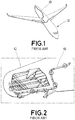
Figure 1 shows a schematic view of an aircraft (12) equipped with the above mentioned bleed air ducts (10) running along thereof. - Conventionally, as showed in the detailed view of
Figure 2 , these bleed air ducts (10) are made of pipes clamped to each other. - These pipes are traditionally made of insulated titanium. As these pipes are rigid, they require the use of flexible or adjustable couplings to compensate the tolerance of the parts (ducts and structural brackets). These couplings provide the needed angles, which are typically fairly small (few degrees), due to the large routing covered by these pipes.
- Nowadays, there are two types of couplings capable of providing an angular adjustment between different pipes: flexible couplings and adjustable couplings.
- Flexible couplings are typically used to compensate for deformation in flight (such as thermal expansion), or decouple loads on some axes. These couplings leave several degrees of freedom even after installation.
Figure 3 shows a detailed view of a flexible coupling (7). - In contrast, adjustable couplings stay fixed after installation and carry loads in flight. These couplings are typically used to provide tight connections while allowing tolerances being adjusted at installation.
-
Figure 4 shows a detailed view of an adjustable coupling (8), specifically a self-aligning duct joint. As shown, the coupling (8) provides a spherical contact surface (9), which allows the coupling to be set at an angle before clamping. After tightening, the coupling (8) transmits loads on all axes, and the connection is fixed. Further, a metallic seal ensures airtightness. - As mentioned, adjustable couplings provide tight and safe connections between pipes of the pneumatic system of an aircraft. However, these kind of couplings are heavy, due to their section size (one 6.5" (16.51cm) connection may weight about 1.55kg) and costly (in the order of magnitude of 1500€ per connection), since the machining is difficult to realize.
- It would therefore be desirable to provide technical means that reduce the weight and cost of the adjustable couplings while simplifying their machining.
- The present invention overcomes the above mentioned drawbacks by providing an angular adjustment coupling that is lighter, cheaper and easier to produce than the angular adjustment coupling traditionally used for connecting pipes of an aircraft.
- One aspect of the present invention refers to an angular adjustment coupling for connecting two pipes of an aircraft that comprises at least two rings having a ramp cross-section to provide thinner and wider sides, and at least three clamps, one clamp disposed between the two rings to fasten one to another at a selectable angular position, and the other two clamps to be disposed between each one of the rings and the pipes to connect said pipes together. The two rings have substantially the same ramp cross-section, so that the angular position is selectable between a minimum angular position in which the wider sides of the rings are arranged at diametrically opposite positions, and a maximum angular position in which the wider sides of the rings are arranged at diametrically coincident positions.
- Thus, the invention offers a new angular adjustment coupling with a simplified design that allows providing different angular positions on the connection of two pipes. The invention drastically reduces the complexity, weight and cost of the traditionally used angular adjustment couplings, by only requiring the use of two ramp rings and three clamps to connect the elements among them. The desired angular positions have to be manually adjusted at installation, unlike the known self-aligning coupling joints, which adjusts itself during connection.
- Further, this angular adjustment coupling provides an easy angle setting that facilitates adjustment and measurement with precision.
- Another aspect of the invention refers to a duct for an aircraft that comprises two pipes, and an angular adjustment coupling as described above and arranged between said two pipes to connect one to another at a selectable angular position.
- The duct of the invention provides adjustable couplings that allow compensating for tolerance, at the same time that weight, cost and complexity are reduced compared to traditional ducts equipped with traditional couplings.
- For a better comprehension of the invention, the following drawings are provided for illustrative and non-limiting purposes, wherein:
-
Figure 1 shows a schematic view of an aircraft equipped with bleed air ducts running along the wings and fuselage. -
Figure 2 shows a detailed view ofFigure 1 in which bleed air duct sections clamped to each other are illustrated. -
Figure 3 shows a detailed view of a flexible coupling of the state of the art. -
Figure 4 shows a detailed view of an adjustable coupling of the state of the art. -
Figure 5 shows a schematic lateral view (drawing A and drawing B) and perspective view (drawing C) of different ring arrangements of an angular adjustment coupling, according to a preferred embodiment of the present invention. Drawing A shows a ring arrangement setting a minimum angular position between the pipes. Drawing B shows a ring arrangement setting a maximum angular position between the pipes. Drawing C shows a ring arrangement setting an intermediate angular position between the pipes. -
Figure 6 shows a perspective view (drawing A) and a lateral view (drawing B) of a prototype of an angular adjustment coupling, according to a preferred embodiment of the present invention. -
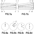
Figure 7 shows a schematic frontal view of the angular adjustment coupling set on a minimum angular position (drawing A) and on a maximum angular position (drawing B). -
Figure 8 shows representative views of directions and values resulting from different angular positions of the rings of the angular adjustment coupling. Drawing A shows a maximum setting angle value. Drawing B and drawing C show intermediate setting angle values. Drawing D shows a minimum setting angle value. -
Figures 5a, 5b and 5c show an angular adjustment coupling (1) according to a preferred embodiment. According to the invention, the angular adjustment coupling (1) for connecting two pipes (10a, 10b) for an aircraft (12) comprises two rings (2) having a ramp cross-section (angled rings) to provide thinner (2') and wider sides (2"), and three clamps (3). As shown, two clamps (3) are arranged between each one of the pipes (10a, 10b) and each one of the rings (2), and the other clamp (3) is arranged between the two rings (2). - The variable cross-section of the rings (2) enables to provide a selectable angular position between them, and transferred this angular position (angular variation) to the pipes (10a, 10b) when they are connected.
-
Figure 5a shows the rings (2) of the angular adjustment coupling (1) arranged for setting a minimum angular difference between the pipes (10a, 10b). This minimum angular difference is established by a minimum angular position in which the wider sides (2") of the rings (2) are arranged at diametrically opposite positions. -
Figure 5b shows the rings (2) of the angular adjustment coupling (1) arranged for setting a maximum angular difference between the pipes (10a, 10b). This maximum angular difference is established by a maximum angular position in which the wider sides (2") of the rings (2) are arranged at diametrically coincident positions. -
Figure 5c shows the rings (2) of the angular adjustment coupling (1) arranged for setting an intermediate angular difference between the pipes (10a, 10b). This intermediate angular difference is established by an intermediate angular position in which the wider sides (2") of the rings are arranged between diametrically opposite and diametrically coincident positions. -
Figures 5a, 5b and 5c further show the intersections (13) between the pipes (10a, 10b) and/or the rings (2) in which the clamps (3) would be arranged. -
Figures 6a and 6b show a perspective and a lateral view of a prototype of an angular adjustment coupling (1). - As shown in
Figures 6a and 6b , and according to a preferred embodiment, at least one of the clamps (3) consists of a V-clamp. This kind of clamps provides a simple and cost-effective connection. - According to another preferred embodiment, the wider sides (2") of the rings (2) have a lateral protrusion (5) to be visually identified. This way, the desired angle will be easily set at installation, since this desired value is very small (around 1 to 4 degrees) and thus very difficult to identify.
- Preferentially, and as shown in
Figures 6a and 6b , each lateral protrusion (5) has a notch (6) at the widest side (2") of the ring (2) to identify the maximum angular deviation. -
Figures 6a and 6b show an angular adjustment coupling (1) in which a maximum angular position of 2 geometric degrees is established. This maximum angular position establishes up to 4 geometric degrees of difference between the longitudinal axes (4a, 4b) of the two pipes (10a, 10b). In contrast, if a minimum angular position would be established, a zero-degree coupling would be provided, and the longitudinal axes (4a, 4b) of the two pipes (10a, 10b) would be coincident. -
Figure 7 shows a schematic front view of an angular adjustment coupling (1) set on a minimum angular position (Figure 7a ) and on a maximum angular position (Figure 7b ). -
Figure 8a-8d schematically show different views of directions and values resulting from different radial positions of the rings of the angular adjustment coupling. -
Figure 8a shows the maximum value of the resultant setting angle, in which the widest sides of both rings are oriented towards the same direction. -
Figure 8b and 8c show intermediate values of the resultant setting angle, in which both rings are oriented towards different directions, excluding coincident (showed inFigure 8a ) and opposite (showed inFigure 8d ). - The setting angle between the pipes can be set in any direction, and at any angle between 0° (minimum setting angle value) and two times the geometric angle of the rings. The geometric angle of the rings is the angle defined by their ramp, that is, between their thinner and wider sides. The geometric angle of the rings is set by their machining, and can be chosen freely for the amount of adjustment needed.
- Calling the ring geometric angle "α", and the radial angle between the rings "β", the setting angle "γ" will be:

- The direction of the setting angle of the angular adjustment coupling is the middle (the average) of the setting directions of both rings.
-
Figure 8d finally shows the minimum value of the resultant setting angle, in which the widest sides of both rings are oriented away from each other (in opposite directions). - The invention finally refers to a duct (10) for an aircraft (12) that comprises two pipes (10a, 10b), and an angular adjustment coupling (1) as described above and arranged between said two pipes (10a, 10b) to connect one pipe to another at a selectable angular position.
- The duct has a lower weight, cost and complexity in comparison with traditional ducts equipped with traditional couplings. Further, the duct allows compensating for tolerance in the coupling of the sections.
Claims (7)
- Angular adjustment coupling (1) for connecting two pipes (10a, 10b) of an aircraft (12) comprising:- at least two rings (2) having a ramp cross-section to provide thinner and wider sides (2', 2"), and- at least three clamps (3), one clamp (3) disposed between the two rings (2) to fasten one to another at a selectable angular position, and the other two clamps (3) to be disposed between each one of the rings (2) and the pipes (10a, 10b) to connect said pipes together,- wherein the two rings (2) have substantially the same ramp cross-section, so that the angular position is selectable between a minimum angular position in which the wider sides (2") of the rings (2) are arranged at diametrically opposite positions, and a maximum angular position in which the wider sides (2") of the rings (2) are arranged at diametrically coincident positions.
- Angular adjustment coupling (1) for connecting two pipes (10a, 10b) of an aircraft (12), according to claim 1, wherein the minimum angular position corresponds to a zero-degree coupling in which the longitudinal axes (4a, 4b) of the two pipes (10a, 10b) are coincident.
- Angular adjustment coupling (1) for connecting two pipes (10a, 10b) of an aircraft (12), according to any preceding claims, wherein the maximum angular position ranges from 1 to 4 geometric degrees of difference between the longitudinal axes (4a, 4b) of the two pipes (10a, 10b).
- Angular adjustment coupling (1) for connecting two pipes (10a, 10b) of an aircraft (12), according to any preceding claims, wherein the wider sides (2") of the rings (2) have a lateral protrusion (5) to be visually identified.
- Angular adjustment coupling (1) for connecting two pipes (10a, 10b) of an aircraft (12), according to claim 4, wherein the lateral protrusion (5) has a notch (6) at the widest side (2") of the ring (2).
- Angular adjustment coupling (1) for connecting two pipes (10a, 10b) of an aircraft (12), according to any preceding claims, wherein at least one of the clamps (3) consists of a V-clamp.
- A duct (10) for an aircraft (12) comprising two pipes (10a, 10b), and an angular adjustment coupling (1) according to any of claims 1-6 arranged between said two pipes (10a, 10b) to connect one pipe to another at a selectable angular position.
Priority Applications (1)
| Application Number | Priority Date | Filing Date | Title |
|---|---|---|---|
| EP17382577.9A EP3447354A1 (en) | 2017-08-21 | 2017-08-21 | Angular adjustment coupling for connecting two pipes of an aircraft |
Applications Claiming Priority (1)
| Application Number | Priority Date | Filing Date | Title |
|---|---|---|---|
| EP17382577.9A EP3447354A1 (en) | 2017-08-21 | 2017-08-21 | Angular adjustment coupling for connecting two pipes of an aircraft |
Publications (1)
| Publication Number | Publication Date |
|---|---|
| EP3447354A1 true EP3447354A1 (en) | 2019-02-27 |
Family
ID=59829318
Family Applications (1)
| Application Number | Title | Priority Date | Filing Date |
|---|---|---|---|
| EP17382577.9A Withdrawn EP3447354A1 (en) | 2017-08-21 | 2017-08-21 | Angular adjustment coupling for connecting two pipes of an aircraft |
Country Status (1)
| Country | Link |
|---|---|
| EP (1) | EP3447354A1 (en) |
Citations (5)
| Publication number | Priority date | Publication date | Assignee | Title |
|---|---|---|---|---|
| US776971A (en) * | 1904-04-22 | 1904-12-06 | American Distr Steam Company | Pipe-coupling. |
| FR737761A (en) * | 1932-05-28 | 1932-12-16 | Intermediate connection | |
| JP2002195472A (en) * | 2000-12-28 | 2002-07-10 | On Industries Ltd | Pipe fittings |
| WO2008152643A2 (en) * | 2007-06-12 | 2008-12-18 | Krausz Industries Development Ltd. | Multi-angle joint |
| DE102008030195A1 (en) * | 2007-07-31 | 2009-02-05 | Franz Ehrenleitner | Conveying device for conveying media e.g. concrete, has tube joint connecting two tube sections, and cantilever arm driven to force orientation of segment relative to sections and tube segment by movement of arms, when pipeline is passive |
-
2017
- 2017-08-21 EP EP17382577.9A patent/EP3447354A1/en not_active Withdrawn
Patent Citations (5)
| Publication number | Priority date | Publication date | Assignee | Title |
|---|---|---|---|---|
| US776971A (en) * | 1904-04-22 | 1904-12-06 | American Distr Steam Company | Pipe-coupling. |
| FR737761A (en) * | 1932-05-28 | 1932-12-16 | Intermediate connection | |
| JP2002195472A (en) * | 2000-12-28 | 2002-07-10 | On Industries Ltd | Pipe fittings |
| WO2008152643A2 (en) * | 2007-06-12 | 2008-12-18 | Krausz Industries Development Ltd. | Multi-angle joint |
| DE102008030195A1 (en) * | 2007-07-31 | 2009-02-05 | Franz Ehrenleitner | Conveying device for conveying media e.g. concrete, has tube joint connecting two tube sections, and cantilever arm driven to force orientation of segment relative to sections and tube segment by movement of arms, when pipeline is passive |
Similar Documents
| Publication | Publication Date | Title |
|---|---|---|
| EP3535515B1 (en) | Spherical compensator junction assembly for high pressure ducting system | |
| US10428986B2 (en) | Gimbal expansion joint | |
| US9278759B2 (en) | Cabin air compressor cross-support bracket | |
| JPS6124594B2 (en) | ||
| US20090079186A1 (en) | Flexible fitting for rigid tubing assembly | |
| EP2034136A2 (en) | Scalloped flexure ring | |
| US3556568A (en) | Conduit connection means | |
| EP2930113A1 (en) | System and method for fastening structures | |
| MX2008015789A (en) | Engine exhaust system with directional nozzle. | |
| EP3543575A1 (en) | A clamp assembly and method of clamping | |
| CN102414422B (en) | One-piece mounting for aeronautical apparatuses | |
| US20190309886A1 (en) | Device For Connecting Pipe Ends Of Double-Walled Pipes | |
| JP2008542640A (en) | Connecting member for tube with joint | |
| US20160230912A1 (en) | Double hinge flex joint | |
| US20130025963A1 (en) | Air conditioning system exhaust silencer for an aircraft | |
| US12234930B2 (en) | Multipart pipe joint | |
| US9599132B2 (en) | Anti-rotation lug for mounting components together | |
| EP3070387B1 (en) | Flexible coupling with rotational capability | |
| MX2008015788A (en) | Engine exhaust system. | |
| US10301036B2 (en) | Suspension of a tubular element in an aircraft compartment | |
| EP3378781A1 (en) | Fume tight sock collector/box | |
| EP3647201A1 (en) | Anti-icing system for an aircraft nacelle | |
| EP2653764B1 (en) | Duct fittings | |
| US9297404B2 (en) | Single tool installation/removal of restraint cable with anti-rotation feature | |
| EP2837776B1 (en) | A panel attachment system |
Legal Events
| Date | Code | Title | Description |
|---|---|---|---|
| PUAI | Public reference made under article 153(3) epc to a published international application that has entered the european phase |
Free format text: ORIGINAL CODE: 0009012 |
|
| STAA | Information on the status of an ep patent application or granted ep patent |
Free format text: STATUS: THE APPLICATION HAS BEEN PUBLISHED |
|
| AK | Designated contracting states |
Kind code of ref document: A1 Designated state(s): AL AT BE BG CH CY CZ DE DK EE ES FI FR GB GR HR HU IE IS IT LI LT LU LV MC MK MT NL NO PL PT RO RS SE SI SK SM TR |
|
| AX | Request for extension of the european patent |
Extension state: BA ME |
|
| STAA | Information on the status of an ep patent application or granted ep patent |
Free format text: STATUS: THE APPLICATION IS DEEMED TO BE WITHDRAWN |
|
| 18D | Application deemed to be withdrawn |
Effective date: 20190828 |