EP3447303A1 - Heat dissipation blade and heat dissipation fan - Google Patents
Heat dissipation blade and heat dissipation fan Download PDFInfo
- Publication number
- EP3447303A1 EP3447303A1 EP18189917.0A EP18189917A EP3447303A1 EP 3447303 A1 EP3447303 A1 EP 3447303A1 EP 18189917 A EP18189917 A EP 18189917A EP 3447303 A1 EP3447303 A1 EP 3447303A1
- Authority
- EP
- European Patent Office
- Prior art keywords
- heat dissipation
- blade
- flow guiding
- guiding portion
- concave
- Prior art date
- Legal status (The legal status is an assumption and is not a legal conclusion. Google has not performed a legal analysis and makes no representation as to the accuracy of the status listed.)
- Granted
Links
Images



Classifications
-
- F—MECHANICAL ENGINEERING; LIGHTING; HEATING; WEAPONS; BLASTING
- F04—POSITIVE - DISPLACEMENT MACHINES FOR LIQUIDS; PUMPS FOR LIQUIDS OR ELASTIC FLUIDS
- F04D—NON-POSITIVE-DISPLACEMENT PUMPS
- F04D29/00—Details, component parts, or accessories
- F04D29/26—Rotors specially for elastic fluids
- F04D29/28—Rotors specially for elastic fluids for centrifugal or helico-centrifugal pumps for radial-flow or helico-centrifugal pumps
- F04D29/281—Rotors specially for elastic fluids for centrifugal or helico-centrifugal pumps for radial-flow or helico-centrifugal pumps for fans or blowers
-
- F—MECHANICAL ENGINEERING; LIGHTING; HEATING; WEAPONS; BLASTING
- F04—POSITIVE - DISPLACEMENT MACHINES FOR LIQUIDS; PUMPS FOR LIQUIDS OR ELASTIC FLUIDS
- F04D—NON-POSITIVE-DISPLACEMENT PUMPS
- F04D29/00—Details, component parts, or accessories
- F04D29/26—Rotors specially for elastic fluids
- F04D29/28—Rotors specially for elastic fluids for centrifugal or helico-centrifugal pumps for radial-flow or helico-centrifugal pumps
- F04D29/30—Vanes
-
- F—MECHANICAL ENGINEERING; LIGHTING; HEATING; WEAPONS; BLASTING
- F04—POSITIVE - DISPLACEMENT MACHINES FOR LIQUIDS; PUMPS FOR LIQUIDS OR ELASTIC FLUIDS
- F04D—NON-POSITIVE-DISPLACEMENT PUMPS
- F04D29/00—Details, component parts, or accessories
- F04D29/66—Combating cavitation, whirls, noise, vibration or the like; Balancing
- F04D29/661—Combating cavitation, whirls, noise, vibration or the like; Balancing especially adapted for elastic fluid pumps
- F04D29/666—Combating cavitation, whirls, noise, vibration or the like; Balancing especially adapted for elastic fluid pumps by means of rotor construction or layout, e.g. unequal distribution of blades or vanes
-
- F—MECHANICAL ENGINEERING; LIGHTING; HEATING; WEAPONS; BLASTING
- F05—INDEXING SCHEMES RELATING TO ENGINES OR PUMPS IN VARIOUS SUBCLASSES OF CLASSES F01-F04
- F05B—INDEXING SCHEME RELATING TO WIND, SPRING, WEIGHT, INERTIA OR LIKE MOTORS, TO MACHINES OR ENGINES FOR LIQUIDS COVERED BY SUBCLASSES F03B, F03D AND F03G
- F05B2240/00—Components
- F05B2240/20—Rotors
- F05B2240/30—Characteristics of rotor blades, i.e. of any element transforming dynamic fluid energy to or from rotational energy and being attached to a rotor
- F05B2240/301—Cross-section characteristics
-
- F—MECHANICAL ENGINEERING; LIGHTING; HEATING; WEAPONS; BLASTING
- F05—INDEXING SCHEMES RELATING TO ENGINES OR PUMPS IN VARIOUS SUBCLASSES OF CLASSES F01-F04
- F05B—INDEXING SCHEME RELATING TO WIND, SPRING, WEIGHT, INERTIA OR LIKE MOTORS, TO MACHINES OR ENGINES FOR LIQUIDS COVERED BY SUBCLASSES F03B, F03D AND F03G
- F05B2250/00—Geometry
- F05B2250/70—Shape
- F05B2250/71—Shape curved
- F05B2250/711—Shape curved convex
-
- F—MECHANICAL ENGINEERING; LIGHTING; HEATING; WEAPONS; BLASTING
- F05—INDEXING SCHEMES RELATING TO ENGINES OR PUMPS IN VARIOUS SUBCLASSES OF CLASSES F01-F04
- F05B—INDEXING SCHEME RELATING TO WIND, SPRING, WEIGHT, INERTIA OR LIKE MOTORS, TO MACHINES OR ENGINES FOR LIQUIDS COVERED BY SUBCLASSES F03B, F03D AND F03G
- F05B2250/00—Geometry
- F05B2250/70—Shape
- F05B2250/71—Shape curved
- F05B2250/712—Shape curved concave
-
- F—MECHANICAL ENGINEERING; LIGHTING; HEATING; WEAPONS; BLASTING
- F05—INDEXING SCHEMES RELATING TO ENGINES OR PUMPS IN VARIOUS SUBCLASSES OF CLASSES F01-F04
- F05B—INDEXING SCHEME RELATING TO WIND, SPRING, WEIGHT, INERTIA OR LIKE MOTORS, TO MACHINES OR ENGINES FOR LIQUIDS COVERED BY SUBCLASSES F03B, F03D AND F03G
- F05B2260/00—Function
- F05B2260/20—Heat transfer, e.g. cooling
- F05B2260/221—Improvement of heat transfer
- F05B2260/224—Improvement of heat transfer by increasing the heat transfer surface
-
- F—MECHANICAL ENGINEERING; LIGHTING; HEATING; WEAPONS; BLASTING
- F05—INDEXING SCHEMES RELATING TO ENGINES OR PUMPS IN VARIOUS SUBCLASSES OF CLASSES F01-F04
- F05D—INDEXING SCHEME FOR ASPECTS RELATING TO NON-POSITIVE-DISPLACEMENT MACHINES OR ENGINES, GAS-TURBINES OR JET-PROPULSION PLANTS
- F05D2240/00—Components
- F05D2240/20—Rotors
- F05D2240/30—Characteristics of rotor blades, i.e. of any element transforming dynamic fluid energy to or from rotational energy and being attached to a rotor
- F05D2240/305—Characteristics of rotor blades, i.e. of any element transforming dynamic fluid energy to or from rotational energy and being attached to a rotor related to the pressure side of a rotor blade
-
- F—MECHANICAL ENGINEERING; LIGHTING; HEATING; WEAPONS; BLASTING
- F05—INDEXING SCHEMES RELATING TO ENGINES OR PUMPS IN VARIOUS SUBCLASSES OF CLASSES F01-F04
- F05D—INDEXING SCHEME FOR ASPECTS RELATING TO NON-POSITIVE-DISPLACEMENT MACHINES OR ENGINES, GAS-TURBINES OR JET-PROPULSION PLANTS
- F05D2240/00—Components
- F05D2240/20—Rotors
- F05D2240/30—Characteristics of rotor blades, i.e. of any element transforming dynamic fluid energy to or from rotational energy and being attached to a rotor
- F05D2240/307—Characteristics of rotor blades, i.e. of any element transforming dynamic fluid energy to or from rotational energy and being attached to a rotor related to the tip of a rotor blade
-
- F—MECHANICAL ENGINEERING; LIGHTING; HEATING; WEAPONS; BLASTING
- F05—INDEXING SCHEMES RELATING TO ENGINES OR PUMPS IN VARIOUS SUBCLASSES OF CLASSES F01-F04
- F05D—INDEXING SCHEME FOR ASPECTS RELATING TO NON-POSITIVE-DISPLACEMENT MACHINES OR ENGINES, GAS-TURBINES OR JET-PROPULSION PLANTS
- F05D2250/00—Geometry
- F05D2250/70—Shape
- F05D2250/71—Shape curved
- F05D2250/712—Shape curved concave
Definitions
- the invention relates to a blade and a fan, and particularly relates to a heat dissipation blade and a heat dissipation fan.
- Heat dissipation fans are disposed in most of the common electronic apparatuses, such as servers, main bodies of personal desktop computers, all-in-one (AIO) computers, laptop computers, or displays. Through an airflow generated by the heat dissipation fan, heat generated during operation of the electronic apparatus is discharged out of the apparatus.
- AIO all-in-one
- centrifugal fans As an example, a centrifugal fan is normally manufactured by integrally forming a hub and blades through plastic injection. Due to limitations on materials and manufacturing processes, it is difficult to reduce the thickness of the plastic blades. As a consequence, it is challenging to increase the number of plastic blades arranged on the circumference of the hub. If the number of plastic blades is increased, a total weight of the centrifugal fan may be significantly increased. Due to an excessive load, if a fan speed of the centrifugal fan is increased, high-frequency noises may be generated.
- the invention provides a heat dissipation fan and heat dissipation blades capable of increasing heat dissipation efficiency.
- a heat dissipation blade is adapted to be fixed to a hub.
- the heat dissipation blade includes a curved surface body and a flow guiding portion.
- the curved surface body has a pressure bearing surface and a negative pressing surface opposite to the pressure bearing surface.
- the flow guiding portion is connected to the curved surface body.
- the flow guiding portion has a concave surface and a convex surface opposite to the concave surface, the concave surface is recessed in the pressure bearing surface, and the convex surface protrudes outward from the negative pressing surface.
- a heat dissipation fan includes a hub and a plurality of heat dissipation blades.
- the heat dissipation blades are arranged around the periphery of the hub.
- Each of the heat dissipation blades includes a curved surface body and a flow guiding portion.
- the curved surface body has a pressure bearing surface and a negative pressing surface opposite to the pressure bearing surface.
- the flow guiding portion is connected to the curved surface body.
- the flow guiding portion has a concave surface and a convex surface opposite to the concave surface, the concave surface is recessed in the pressure bearing surface, and the convex surface protrudes outward from the negative pressing surface.
- the heat dissipation blades in the heat dissipation fan have a greater flow guiding area.
- a flow rate of the heat dissipation airflow may be increased to attain desirable heat dissipation efficiency.
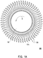
- FIG. 1A is a schematic view illustrating a heat dissipation fan according to a first embodiment of the invention.
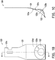
- FIG. 1B is a schematic view illustrating a heat dissipation blade according to the first embodiment of the invention.
- FIG. 1C is a schematic cross-sectional view illustrating the heat dissipation blade of FIG. 1B taken along a cross-sectional line A-A.
- a heat dissipation fan 100 may be a centrifugal fan.
- the heat dissipation fan 100 includes a hub 110 and a plurality of heat dissipation blades 120.
- the heat dissipation blades 120 are arranged around the periphery of the hub 110.
- the hub 110 and the heat dissipation blades 120 respectively fixed to the hub 110 may be manufactured by insert molding, for example. During manufacturing, one end of each of the heat dissipation blades 120 is placed in a molding cavity for forming the hub 110, and then the hub 110 is formed in the molding cavity by injection molding. Accordingly, the heat dissipation blades 120 are fixed to the hub 110 when the hub 110 is manufactured.
- the hub 110 may be plastic, and the heat dissipation blades 120 may be metallic. However, the invention does not intend to impose a limitation on the materials of the hub and the heat dissipation blades.
- the heat dissipation blade 120 includes a curved surface body 121 and a flow guiding portion 122.
- the curved surface body 121 is described as being connected to one flow guiding portion 122 in the embodiment.
- the heat dissipation fan 100 is configured to rotate along a rotating direction R, such as a counterclockwise direction.
- the curved surface body 121 has a pressure bearing surface 121a and a negative pressing surface 121b opposite to the pressure bearing surface 121a.
- the pressure bearing surface 121a is configured to receive an airflow entering the heat dissipation fan 100 when the heat dissipation fan 100 operates.
- the curved surface body 121 further has a combining end 121c and a flow guiding end 121d opposite to the combining end 121c.
- the combining end 121c is fixed to the hub 110, and the flow guiding portion 122 is disposed to be adjacent to an end edge of the flow guiding end 121d.
- a distance between the flow guiding portion 122 and the hub 110 is greater than a distance between the flow guiding portion 122 and the end edge of the flow guiding end 121d.
- the curved surface body 121 and the flow guiding portion 122 may be an integrally formed sheet metal component.
- the flow guiding portion 122 is formed at the curved surface body 121 by punching.
- the flow guiding portion 122 has a concave surface 122a and a convex surface 122b opposite to the concave surface 122a.
- the concave surface 122a is recessed in the pressure bearing surface 121a, and the convex surface 122b protrudes outward from the negative pressing surface 121b.
- the pressuring bearing surface 121a of the curved surface body 121 and the concave surface 122a of the flow guiding portion 122 smoothly connected to each other define a flow guiding surface receiving the airflow entering the heat dissipation fan 100 when the heat dissipation fan 100 operates.
- the flow guiding surface of the heat dissipation blade 120 of the embodiment has a greater area.
- the heat dissipation blades 120 arranged around the periphery of the hub 110 are able to increase a flow rate of a heat dissipation airflow to attain desirable heat dissipation efficiency.
- the pressure bearing surface 121a of the curved surface body 121 and the concave surface 122a of the flow guiding portion 122 are respectively concave curved surfaces, and radii of curvature of the pressure bearing surface 121a and the concave surface 122a are different.
- the negative pressing surface 121b of the curved surface body 121 and the convex surface 122b of the flow guiding portion 122 are respectively convex curved surfaces, and radii of curvature of the negative pressing surface 121b and the convex surface 122b are different.
- the concave surface of the flow guiding portion may also be an inclined surface, a stepped surface, other irregular surfaces, or a combination of at least two of the curved surface, the inclined surface, and the stepped surface.
- a flow rate of a heat dissipation airflow of the conventional heat dissipation fan may be increased by increasing a fan speed or the number of heat dissipation blades
- the motor may bear an excessive load or high-frequency noises may be generated.
- the heat dissipation fan 100 of the embodiment is still able to increase the flow rate of the heat dissipation airflow. Therefore, the load of the motor may be reduced, and the high-frequency noises may be avoided.
- the flow rate of the heat dissipation airflow generated per unit time by the heat dissipation fan 100 of the embodiment is greater than the flow rate of the heat dissipation air flow generated per unit time by the conventional heat dissipation fan (e.g., a fan configured with plate-like heat dissipation blades or heat dissipation blades each with a single curved surface).
- the conventional heat dissipation fan e.g., a fan configured with plate-like heat dissipation blades or heat dissipation blades each with a single curved surface.
- the heat dissipation fan 100 of the embodiment is still able to generate the heat dissipation airflow with the same flow rate as that of the conventional heat dissipation fan (e.g., a fan configured with plate-like heat dissipation blades or heat dissipation blades each with a single curved surface).
- the conventional heat dissipation fan e.g., a fan configured with plate-like heat dissipation blades or heat dissipation blades each with a single curved surface.
- the heat dissipation fan 100 of the embodiment is still able to generate the heat dissipation airflow with the same flow rate as that of the conventional heat dissipation fan (e.g., a fan configured with plate-like heat dissipation blades or heat dissipation blades each with a single curved surface).
- the conventional heat dissipation fan e.g., a fan configured with plate-like heat dissipation blades or heat dissipation blades each with a single curved surface.
- heat dissipation blades 220 to 420 of other embodiments are described as examples.
- the heat dissipation blades 220 to 420 in the embodiments are applicable as the heat dissipation blades of the invention.
- the heat dissipation blades 220 to 240 follow design principles same as or similar to those of the heat dissipation blades 120 of the first embodiments, and structures of the dissipation blades 220 to 240 are substantially similar to the structure of the heat dissipation blades 120 of the first embodiment.
- descriptions about the technical contents and effects the same as those of the first embodiment are omitted in the embodiments.
- FIG. 2A is a schematic view illustrating a heat dissipation blade according to a second embodiment of the invention.
- FIG. 2B is a schematic cross-sectional view illustrating the heat dissipation blade of FIG. 2A taken along a cross-sectional line B-B.
- the heat dissipation blade 220 of the embodiment is substantially similar to the heat dissipation blade 120 of the first embodiment.
- a difference therebetween is that geometric shapes of the concave surfaces of the flow guiding portions are different.
- the geometric shape of the concave surface 122a of the flow guiding portion 122 is nearly circular or elliptic, as shown in FIG. 1A .
- a concave surface 222a of a flow guiding portion 222 is in a geometric shape where a width is increased from a combining end 221c toward an end edge of a flow guiding end 221d (i.e., along a direction DR).
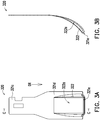
- FIG. 3A is a schematic view illustrating a heat dissipation blade according to a third embodiment of the invention.
- FIG. 3B is a schematic cross-sectional view illustrating the heat dissipation blade of FIG. 3A taken along a cross-sectional line C-C.
- the heat dissipation blade 320 of the embodiment is substantially similar to the heat dissipation blade 220 of the second embodiment. A difference therebetween is that geometric shapes of the concave surfaces of the flow guiding portions are different.
- the concave surface 222a of the flow guiding portion 222 is in a geometric shape where the width is increased from the combining end 221c toward the end edge of the flow guiding end 221d (i.e., along the direction DR).
- a concave surface 322a of a flow guiding portion 322 is in a geometric shape where a width is increased from a combining end 321c toward an end edge of a flow guiding end 321d (i.e., along the direction DR), and the flow guiding portion 322 is formed with an opening 321e at the end edge of the flow guiding end 321d.
- a variation in width of the concave surface 222a of the flow guiding portion 222 of the second embodiment is greater than a variation in width of the concave surface 322a of the flow guiding portion 322 of the embodiment.
- FIG. 4A is a schematic view illustrating a heat dissipation blade according to a fourth embodiment of the invention.
- FIG. 4B is a schematic cross-sectional view illustrating the heat dissipation blade of FIG. 4A taken along a cross-sectional line D-D.
- the heat dissipation blade 420 of the embodiment is substantially similar to the heat dissipation blade 120 of the first embodiment. A difference therebetween lies in sizes and numbers of the flow guiding portions. In the embodiment, the number of a flow guiding portion 422 is plural.
- the flow guiding portions 422 are arranged into a matrix, and an area of a concave surface 422a of each of the flow guiding portions 422 is smaller than an area of the concave surface 122a of the flow guiding portion 122 of the first embodiment.
- heat dissipation fan 100A of another embodiment is described as an example.
- Heat dissipation blades in the heat dissipation fan 100A of the embodiment are substantially similar to the heat dissipation blades 120 of the first embodiment.
- descriptions about the technical contents and effects the same as those of the first embodiment are omitted in the following.
- FIG. 5 is a schematic view illustrating a heat dissipation fan according to another embodiment of the invention.
- the heat dissipation blades (including a plurality of first blades 120a, a plurality of second blades 120b, and a plurality of third blades 120c) are in a geometric shape substantially similar to the heat dissipation blades 120 in the heat dissipation fan 100 of the first embodiment.
- the embodiment differs in that the heat dissipation blades are regularly arranged on the periphery of the hub 110 along a rotational direction R in an order from the first blade 120a to the second blade 120b and then to the third blade 120c (i.e., each of the second blades 120b is disposed between one of the first blades 120a and one of the third blades 120c that are adjacent).
- a depth D1 of a flow guiding portion 1221 of the first blade 120a is less than a depth D2 of a flow guiding portion 1222 of the second blade 120b
- the depth D2 of the flow guiding portion 1222 of the second blade 120b is less than a depth D3 of a flow guiding portion 1223 of the third blade 120c.
- an area of a flow guiding surface of the first blade 120a for receiving an airflow is smaller than an area of a flow guiding surface of the second blade 120b for receiving an air flow
- the area of the flow guiding surface of the second blade 120b for receiving the air flow is smaller than an area of a flow guiding surface of the third blade 120c for receiving an airflow.
- the heat dissipation blades arranged around the periphery of the hub may be regularly arranged along the rotational direction of the heat dissipation fan in an ascending or descending order based the areas of the flow guiding surfaces for receiving the airflows.
- the depths of the flow guiding portions 122 of the heat dissipation blades 120 and the areas of the flow guiding surfaces of the heat dissipation blades 120 for receiving the airflows in the heat dissipation fan 100 of the first embodiment are the same.
- an entrance angle I1 and an exit angle O1 of the first blade 120a, an entrance angle 12 and an exit angle O2 of the second blade 120b, and an entrance angle 13 and an exit angle O3 of the third blade 120c are respectively different.
- the hub 110 has an outer circumference (represented by a dot dash line passing through where the heat dissipation blades and the hub 110 are connected in the figure).
- the entrance angles are defined as angles included between tangent lines passing through the curved surface bodies of the heat dissipation blades and tangent lines passing through the outer circumference of the hub 110.
- the end edges of the heat dissipation blades define an outer circumference (represented by a dot dash line passing through the end edges of the heat dissipation blades in the figure).
- exit angles are defined as angles included between tangent lines passing through the curved surface bodies of the heat dissipation blades and tangent lines passing through the outer circumference defined by the end edges of the heat dissipation blades.
- the areas of the flow guiding surfaces for receiving the air flows of the first blade 120a, the second blade 120b, and the third blade 120c are respectively different, pressures exerted at the flow guiding surfaces of the first blade 120a, the second blade 120b, and the third blade 120c when the heat dissipation fan 100A operates are also respectively different. Therefore, energy is dispersed and high-frequency noises are avoided. Besides, since the entrance angles of the first blade 120a, the second blade 120b, and the third blade 120c are configured to be respectively different, and the exit angles of the first blade 120a, the second blade 120b, and the third blade 120c are configured to be respectively different, the energy may also be dispersed, and high-frequency noises may be avoided.
- the invention is not limited thereto.
- the entrance angles of the heat dissipation blades may be configured to be the same, and the exit angles of the heat dissipation blades may also be configured to be the same.
- the entrance angles of the heat dissipation blades may be configured to be the same, but the exit angles of the heat dissipation blades may be configured to be different.
- the entrance angles of the heat dissipation blades may be configured to be different, but the exit angles of the heat dissipation blades may be configured to be the same.
- the heat dissipation blades in the heat dissipation fan have a greater flow guiding area.
- the flow rate of the heat dissipation airflow may be increased to attain desirable heat dissipation efficiency.
- the conventional heat dissipation fan is able to increase the flow rate of the heat dissipation airflow by increasing the fan speed or the number of the heat dissipation blades, the motor may bear an excessive load or high-frequency noises may be generated.
- the heat dissipation fan according to the embodiments of the invention is still able to increase the flow rate of the heat dissipation airflow. Therefore, the load of the motor may be reduced, and the high-frequency noises may be avoided.
Landscapes
- Engineering & Computer Science (AREA)
- Mechanical Engineering (AREA)
- General Engineering & Computer Science (AREA)
- Structures Of Non-Positive Displacement Pumps (AREA)
Abstract
Description
- The invention relates to a blade and a fan, and particularly relates to a heat dissipation blade and a heat dissipation fan.
- Heat dissipation fans are disposed in most of the common electronic apparatuses, such as servers, main bodies of personal desktop computers, all-in-one (AIO) computers, laptop computers, or displays. Through an airflow generated by the heat dissipation fan, heat generated during operation of the electronic apparatus is discharged out of the apparatus.
- Taking centrifugal fans as an example, a centrifugal fan is normally manufactured by integrally forming a hub and blades through plastic injection. Due to limitations on materials and manufacturing processes, it is difficult to reduce the thickness of the plastic blades. As a consequence, it is challenging to increase the number of plastic blades arranged on the circumference of the hub. If the number of plastic blades is increased, a total weight of the centrifugal fan may be significantly increased. Due to an excessive load, if a fan speed of the centrifugal fan is increased, high-frequency noises may be generated.
- The invention provides a heat dissipation fan and heat dissipation blades capable of increasing heat dissipation efficiency.
- A heat dissipation blade according to an embodiment of the invention is adapted to be fixed to a hub. The heat dissipation blade includes a curved surface body and a flow guiding portion. The curved surface body has a pressure bearing surface and a negative pressing surface opposite to the pressure bearing surface. The flow guiding portion is connected to the curved surface body. In addition, the flow guiding portion has a concave surface and a convex surface opposite to the concave surface, the concave surface is recessed in the pressure bearing surface, and the convex surface protrudes outward from the negative pressing surface.
- A heat dissipation fan according to an embodiment of the invention includes a hub and a plurality of heat dissipation blades. The heat dissipation blades are arranged around the periphery of the hub. Each of the heat dissipation blades includes a curved surface body and a flow guiding portion. The curved surface body has a pressure bearing surface and a negative pressing surface opposite to the pressure bearing surface. The flow guiding portion is connected to the curved surface body. In addition, the flow guiding portion has a concave surface and a convex surface opposite to the concave surface, the concave surface is recessed in the pressure bearing surface, and the convex surface protrudes outward from the negative pressing surface.
- Based on the above, the heat dissipation blades in the heat dissipation fan according to the embodiments of the invention have a greater flow guiding area. When the heat dissipation fan operates, a flow rate of the heat dissipation airflow may be increased to attain desirable heat dissipation efficiency.
- In order to make the aforementioned and other features and advantages of the invention comprehensible, several exemplary embodiments accompanied with figures are described in detail below.
- The accompanying drawings are included to provide a further understanding of the invention, and are incorporated in and constitute a part of this specification. The drawings illustrate embodiments of the invention and, together with the description, serve to explain the principles of the invention.
-
FIG. 1A is a schematic view illustrating a heat dissipation fan according to a first embodiment of the invention. -
FIG. 1B is a schematic view illustrating a heat dissipation blade according to the first embodiment of the invention. -
FIG. 1C is a schematic cross-sectional view illustrating the heat dissipation blade ofFIG. 1B taken along a cross-sectional line A-A. -
FIG. 2A is a schematic view illustrating a heat dissipation blade according to a second embodiment of the invention. -
FIG. 2B is a schematic cross-sectional view illustrating the heat dissipation blade ofFIG. 2A taken along a cross-sectional line B-B. -
FIG. 3A is a schematic view illustrating a heat dissipation blade according to a third embodiment of the invention. -
FIG. 3B is a schematic cross-sectional view illustrating the heat dissipation blade ofFIG. 3A taken along a cross-sectional line C-C. -
FIG. 4A is a schematic view illustrating a heat dissipation blade according to a fourth embodiment of the invention. -
FIG. 4B is a schematic cross-sectional view illustrating the heat dissipation blade ofFIG. 4A taken along a cross-sectional line D-D. -
FIG. 5 is a schematic view illustrating a heat dissipation fan according to another embodiment of the invention. - Reference will now be made in detail to the present preferred embodiments of the invention, examples of which are illustrated in the accompanying drawings. Wherever possible, the same reference numbers are used in the drawings and the description to refer to the same or like parts.
-
FIG. 1A is a schematic view illustrating a heat dissipation fan according to a first embodiment of the invention.FIG. 1B is a schematic view illustrating a heat dissipation blade according to the first embodiment of the invention.FIG. 1C is a schematic cross-sectional view illustrating the heat dissipation blade ofFIG. 1B taken along a cross-sectional line A-A. Referring toFIGs. 1A to 1C , in the embodiment, aheat dissipation fan 100 may be a centrifugal fan. Theheat dissipation fan 100 includes ahub 110 and a plurality ofheat dissipation blades 120. In addition, theheat dissipation blades 120 are arranged around the periphery of thehub 110. Thehub 110 and theheat dissipation blades 120 respectively fixed to thehub 110 may be manufactured by insert molding, for example. During manufacturing, one end of each of theheat dissipation blades 120 is placed in a molding cavity for forming thehub 110, and then thehub 110 is formed in the molding cavity by injection molding. Accordingly, theheat dissipation blades 120 are fixed to thehub 110 when thehub 110 is manufactured. Thehub 110 may be plastic, and theheat dissipation blades 120 may be metallic. However, the invention does not intend to impose a limitation on the materials of the hub and the heat dissipation blades. - Taking one of the
heat dissipation blades 120 as an example, theheat dissipation blade 120 includes acurved surface body 121 and aflow guiding portion 122. As an example, thecurved surface body 121 is described as being connected to oneflow guiding portion 122 in the embodiment. For example, theheat dissipation fan 100 is configured to rotate along a rotating direction R, such as a counterclockwise direction. In addition, thecurved surface body 121 has apressure bearing surface 121a and a negativepressing surface 121b opposite to thepressure bearing surface 121a. In addition, thepressure bearing surface 121a is configured to receive an airflow entering theheat dissipation fan 100 when theheat dissipation fan 100 operates. Besides, thecurved surface body 121 further has a combiningend 121c and aflow guiding end 121d opposite to the combiningend 121c. In addition, the combiningend 121c is fixed to thehub 110, and theflow guiding portion 122 is disposed to be adjacent to an end edge of theflow guiding end 121d. In other words, a distance between theflow guiding portion 122 and thehub 110 is greater than a distance between theflow guiding portion 122 and the end edge of theflow guiding end 121d. - The
curved surface body 121 and theflow guiding portion 122 may be an integrally formed sheet metal component. In addition, theflow guiding portion 122 is formed at thecurved surface body 121 by punching. To be more specific, theflow guiding portion 122 has aconcave surface 122a and aconvex surface 122b opposite to theconcave surface 122a. In addition, theconcave surface 122a is recessed in thepressure bearing surface 121a, and theconvex surface 122b protrudes outward from the negativepressing surface 121b. The pressuringbearing surface 121a of thecurved surface body 121 and theconcave surface 122a of theflow guiding portion 122 smoothly connected to each other define a flow guiding surface receiving the airflow entering theheat dissipation fan 100 when theheat dissipation fan 100 operates. Compared with a conventional plate-like heat dissipation blade or heat dissipation blade with a single curved surface, the flow guiding surface of theheat dissipation blade 120 of the embodiment has a greater area. Thus, when theheat dissipation fan 100 operates, theheat dissipation blades 120 arranged around the periphery of thehub 110 are able to increase a flow rate of a heat dissipation airflow to attain desirable heat dissipation efficiency. - In the embodiment, the
pressure bearing surface 121a of thecurved surface body 121 and theconcave surface 122a of theflow guiding portion 122 are respectively concave curved surfaces, and radii of curvature of thepressure bearing surface 121a and theconcave surface 122a are different. Comparatively, the negativepressing surface 121b of thecurved surface body 121 and theconvex surface 122b of theflow guiding portion 122 are respectively convex curved surfaces, and radii of curvature of the negativepressing surface 121b and theconvex surface 122b are different. In other embodiments, the concave surface of the flow guiding portion may also be an inclined surface, a stepped surface, other irregular surfaces, or a combination of at least two of the curved surface, the inclined surface, and the stepped surface. - While a flow rate of a heat dissipation airflow of the conventional heat dissipation fan (e.g., a fan configured with plate-like heat dissipation blades or heat dissipation blades each with a single curved surfaces) may be increased by increasing a fan speed or the number of heat dissipation blades, the motor may bear an excessive load or high-frequency noises may be generated. Comparatively, without increasing the fan speed or the number of heat dissipation blades, the
heat dissipation fan 100 of the embodiment is still able to increase the flow rate of the heat dissipation airflow. Therefore, the load of the motor may be reduced, and the high-frequency noises may be avoided. - Furthermore, under a condition that the fan speeds and the numbers of heat dissipation blades are equal, the flow rate of the heat dissipation airflow generated per unit time by the
heat dissipation fan 100 of the embodiment is greater than the flow rate of the heat dissipation air flow generated per unit time by the conventional heat dissipation fan (e.g., a fan configured with plate-like heat dissipation blades or heat dissipation blades each with a single curved surface). In other words, under a condition that the numbers of heat dissipation blades are the same, even if the fan speed of theheat dissipation fan 100 of the embodiment is slowed down, theheat dissipation fan 100 of the embodiment is still able to generate the heat dissipation airflow with the same flow rate as that of the conventional heat dissipation fan (e.g., a fan configured with plate-like heat dissipation blades or heat dissipation blades each with a single curved surface). To put it differently, under a condition that the fan speeds are the same, even if the number of blades of theheat dissipation fan 100 of the embodiment is reduced, theheat dissipation fan 100 of the embodiment is still able to generate the heat dissipation airflow with the same flow rate as that of the conventional heat dissipation fan (e.g., a fan configured with plate-like heat dissipation blades or heat dissipation blades each with a single curved surface). - In the following,
heat dissipation blades 220 to 420 of other embodiments are described as examples. Theheat dissipation blades 220 to 420 in the embodiments are applicable as the heat dissipation blades of the invention. In addition, theheat dissipation blades 220 to 240 follow design principles same as or similar to those of theheat dissipation blades 120 of the first embodiments, and structures of thedissipation blades 220 to 240 are substantially similar to the structure of theheat dissipation blades 120 of the first embodiment. Thus, descriptions about the technical contents and effects the same as those of the first embodiment are omitted in the embodiments. -
FIG. 2A is a schematic view illustrating a heat dissipation blade according to a second embodiment of the invention.FIG. 2B is a schematic cross-sectional view illustrating the heat dissipation blade ofFIG. 2A taken along a cross-sectional line B-B. Referring toFIGs. 2A and 2B , theheat dissipation blade 220 of the embodiment is substantially similar to theheat dissipation blade 120 of the first embodiment. A difference therebetween is that geometric shapes of the concave surfaces of the flow guiding portions are different. In the first embodiment, the geometric shape of theconcave surface 122a of theflow guiding portion 122 is nearly circular or elliptic, as shown inFIG. 1A . In the embodiment, aconcave surface 222a of aflow guiding portion 222 is in a geometric shape where a width is increased from a combiningend 221c toward an end edge of aflow guiding end 221d (i.e., along a direction DR). -
FIG. 3A is a schematic view illustrating a heat dissipation blade according to a third embodiment of the invention.FIG. 3B is a schematic cross-sectional view illustrating the heat dissipation blade ofFIG. 3A taken along a cross-sectional line C-C. Referring toFIGs. 3A and 3B , theheat dissipation blade 320 of the embodiment is substantially similar to theheat dissipation blade 220 of the second embodiment. A difference therebetween is that geometric shapes of the concave surfaces of the flow guiding portions are different. In the second embodiment, theconcave surface 222a of theflow guiding portion 222 is in a geometric shape where the width is increased from the combiningend 221c toward the end edge of theflow guiding end 221d (i.e., along the direction DR). In the embodiment, aconcave surface 322a of aflow guiding portion 322 is in a geometric shape where a width is increased from a combiningend 321c toward an end edge of aflow guiding end 321d (i.e., along the direction DR), and theflow guiding portion 322 is formed with anopening 321e at the end edge of theflow guiding end 321d. In the direction DR, a variation in width of theconcave surface 222a of theflow guiding portion 222 of the second embodiment is greater than a variation in width of theconcave surface 322a of theflow guiding portion 322 of the embodiment. -
FIG. 4A is a schematic view illustrating a heat dissipation blade according to a fourth embodiment of the invention.FIG. 4B is a schematic cross-sectional view illustrating the heat dissipation blade ofFIG. 4A taken along a cross-sectional line D-D. Referring toFIGs. 4A and 4B , theheat dissipation blade 420 of the embodiment is substantially similar to theheat dissipation blade 120 of the first embodiment. A difference therebetween lies in sizes and numbers of the flow guiding portions. In the embodiment, the number of aflow guiding portion 422 is plural. In addition, theflow guiding portions 422 are arranged into a matrix, and an area of aconcave surface 422a of each of theflow guiding portions 422 is smaller than an area of theconcave surface 122a of theflow guiding portion 122 of the first embodiment. - In the following, a
heat dissipation fan 100A of another embodiment is described as an example. Heat dissipation blades in theheat dissipation fan 100A of the embodiment are substantially similar to theheat dissipation blades 120 of the first embodiment. Thus, descriptions about the technical contents and effects the same as those of the first embodiment are omitted in the following. -
FIG. 5 is a schematic view illustrating a heat dissipation fan according to another embodiment of the invention. Referring toFIG. 5 , the heat dissipation blades (including a plurality offirst blades 120a, a plurality ofsecond blades 120b, and a plurality ofthird blades 120c) are in a geometric shape substantially similar to theheat dissipation blades 120 in theheat dissipation fan 100 of the first embodiment. Nevertheless, the embodiment differs in that the heat dissipation blades are regularly arranged on the periphery of thehub 110 along a rotational direction R in an order from thefirst blade 120a to thesecond blade 120b and then to thethird blade 120c (i.e., each of thesecond blades 120b is disposed between one of thefirst blades 120a and one of thethird blades 120c that are adjacent). In addition, a depth D1 of aflow guiding portion 1221 of thefirst blade 120a is less than a depth D2 of aflow guiding portion 1222 of thesecond blade 120b, and the depth D2 of theflow guiding portion 1222 of thesecond blade 120b is less than a depth D3 of aflow guiding portion 1223 of thethird blade 120c. - In other words, an area of a flow guiding surface of the
first blade 120a for receiving an airflow is smaller than an area of a flow guiding surface of thesecond blade 120b for receiving an air flow, and the area of the flow guiding surface of thesecond blade 120b for receiving the air flow is smaller than an area of a flow guiding surface of thethird blade 120c for receiving an airflow. In other embodiments, the heat dissipation blades arranged around the periphery of the hub may be regularly arranged along the rotational direction of the heat dissipation fan in an ascending or descending order based the areas of the flow guiding surfaces for receiving the airflows. Comparatively, the depths of theflow guiding portions 122 of theheat dissipation blades 120 and the areas of the flow guiding surfaces of theheat dissipation blades 120 for receiving the airflows in theheat dissipation fan 100 of the first embodiment are the same. - Besides, an entrance angle I1 and an exit angle O1 of the
first blade 120a, anentrance angle 12 and an exit angle O2 of thesecond blade 120b, and anentrance angle 13 and an exit angle O3 of thethird blade 120c are respectively different. More specifically, thehub 110 has an outer circumference (represented by a dot dash line passing through where the heat dissipation blades and thehub 110 are connected in the figure). Along where the heat dissipation blades and thehub 110 are connected, the entrance angles are defined as angles included between tangent lines passing through the curved surface bodies of the heat dissipation blades and tangent lines passing through the outer circumference of thehub 110. In addition, the end edges of the heat dissipation blades define an outer circumference (represented by a dot dash line passing through the end edges of the heat dissipation blades in the figure). At the end edges of the heat dissipation blades, exit angles are defined as angles included between tangent lines passing through the curved surface bodies of the heat dissipation blades and tangent lines passing through the outer circumference defined by the end edges of the heat dissipation blades. - In the embodiment, since the areas of the flow guiding surfaces for receiving the air flows of the
first blade 120a, thesecond blade 120b, and thethird blade 120c are respectively different, pressures exerted at the flow guiding surfaces of thefirst blade 120a, thesecond blade 120b, and thethird blade 120c when theheat dissipation fan 100A operates are also respectively different. Therefore, energy is dispersed and high-frequency noises are avoided. Besides, since the entrance angles of thefirst blade 120a, thesecond blade 120b, and thethird blade 120c are configured to be respectively different, and the exit angles of thefirst blade 120a, thesecond blade 120b, and thethird blade 120c are configured to be respectively different, the energy may also be dispersed, and high-frequency noises may be avoided. - Even though the entrance angles of the
first blade 120a, thesecond blade 120b, and thethird blade 120c are configured to be respectively different, and the exit angles of thefirst blade 120a, thesecond blade 120b, and thethird blade 120c are configured to be respectively different in the embodiment, the invention is not limited thereto. In other embodiments, the entrance angles of the heat dissipation blades may be configured to be the same, and the exit angles of the heat dissipation blades may also be configured to be the same. Alternatively, the entrance angles of the heat dissipation blades may be configured to be the same, but the exit angles of the heat dissipation blades may be configured to be different. Or, the entrance angles of the heat dissipation blades may be configured to be different, but the exit angles of the heat dissipation blades may be configured to be the same. - In view of the foregoing, the heat dissipation blades in the heat dissipation fan according to the embodiments of the invention have a greater flow guiding area. When the heat dissipation fan operates, the flow rate of the heat dissipation airflow may be increased to attain desirable heat dissipation efficiency. While the conventional heat dissipation fan is able to increase the flow rate of the heat dissipation airflow by increasing the fan speed or the number of the heat dissipation blades, the motor may bear an excessive load or high-frequency noises may be generated. Comparatively, without increasing the fan speed or the number of heat dissipation blades, the heat dissipation fan according to the embodiments of the invention is still able to increase the flow rate of the heat dissipation airflow. Therefore, the load of the motor may be reduced, and the high-frequency noises may be avoided.
Claims (12)
- A heat dissipation blade (120, 220, 320, 420), adapted to be fixed to a hub (110), characterized in that the heat dissipation blade (120, 220, 320, 420) comprises:a curved surface body (121, 221, 321), having a pressure bearing surface (121a) and a negative pressing surface (121b) opposite to the pressure bearing surface (121a); anda flow guiding portion (122, 222, 322, 422, 1221, 1222, 1223), connected to the curved surface body (121, 221, 321), wherein the flow guiding portion (122, 222, 322, 422, 1221, 1222, 1223) has a concave surface (122a, 222a, 322a, 422a) and a convex surface (122b) opposite to the concave surface (122a, 222a, 322a, 422a), the concave surface (122a, 222a, 322a, 422a) is recessed in the pressure bearing surface (121a), and the convex surface (122b) protrudes outward from the negative pressing surface (121b).
- The heat dissipation blade (120, 220, 320, 420) as claimed in claim 1, characterized in that the curved surface body (121, 221, 321) further has a combining end (121c, 221c, 321c) and a flow guiding end (121d, 221d, 321d) opposite to the combining end (121c, 221c, 321c), the combining end (121c, 221c, 321c) is fixed to the hub (110), and the flow guiding portion (122, 222, 322, 422, 1221, 1222, 1223) is disposed to be adjacent to an end edge of the flow guiding end (121d, 221d, 321d).
- The heat dissipation blade (120, 220, 320, 420) as claimed in claim 1, characterized in that the curved surface body (121, 221, 321) and the flow guiding portion (122, 222, 322, 422, 1221, 1222, 1223) are an integrally formed sheet metal component, and the flow guiding portion (122, 222, 322, 422, 1221, 1222, 1223) is formed at the curved surface body (121, 221, 321) by punching.
- The heat dissipation blade (120, 220, 320, 420) as claimed in claim 1, characterized in that the concave surface (122a, 222a, 322a, 422a) comprises a concave curved surface.
- The heat dissipation blade (120, 220, 320, 420) as claimed in claim 4, characterized in that the pressure bearing surface (121a) comprises a concave curved surface, and a radius of curvature of the pressure bearing surface (121a) is different from a radius of curvature of the concave surface (122a, 222a, 322a, 422a).
- A heat dissipation fan, characterized in that it comprises:a hub (110); anda plurality of heat dissipation blades (120, 220, 320, 420), arranged around a periphery of the hub (110), wherein each of the heat dissipation blades (120, 220, 320, 420) comprises:a curved surface body (121, 221, 321), having a pressure bearing surface (121a) and a negative pressing surface (121b) opposite to the pressure bearing surface (121a); anda flow guiding portion (122, 222, 322, 422, 1221, 1222, 1223), connected to the curved surface body (121, 221, 321), wherein the flow guiding portion (122, 222, 322, 422, 1221, 1222, 1223) has a concave surface (122a, 222a, 322a, 422a) and a convex surface (122b) opposite to the concave surface (122a, 222a, 322a, 422a), the concave surface (122a, 222a, 322a, 422a) is recessed in the pressure bearing surface (121a), and the convex surface (122b) protrudes outward from the negative pressing surface (121b).
- The heat dissipation fan as claimed in claim 6, characterized in that each of the curved surface bodies (121, 221, 321) further has a combining end (121c, 221c, 321c) and a flow guiding end (121d, 221d, 321d) opposite to the combining end (121c, 221c, 321c), each of the combining ends (121c, 221c, 321c) is fixed to the hub (110), and each of the flow guiding portions (122, 222, 322, 422, 1221, 1222, 1223) is disposed to be adjacent to an end edge of the corresponding flow guiding end (121d, 221d, 321d).
- The heat dissipation fan as claimed in claim 6, characterized in that each of the curved surface bodies (121, 221, 321) and the corresponding flow guiding portion (122, 222, 322, 422, 1221, 1222, 1223) are an integrally formed sheet metal component, and each of the flow guiding portions (122, 222, 322, 422, 1221, 1222, 1223) is formed at the corresponding curved surface body (121, 221, 321) by punching.
- The heat dissipation fan as claimed in claim 6, characterized in that each of the concave surfaces (122a, 222a, 322a, 422a) comprises a concave curved surface.
- The heat dissipation fan as claimed in claim 9, characterized in that each of the pressure bearing surfaces (121a) comprises a concave curved surface, and a radius of curvature of each of the pressure bearing surfaces (121a) is different from a radius of curvature of the corresponding concave surface (122a, 222a, 322a, 422a).
- The heat dissipation fan as claimed in claim 6, characterized in that the heat dissipation blades (120, 220, 320, 420) comprise a first blade (120a), a second blade (120b), and a third blade (120c), a depth (D1) of the flow guiding portion (122, 222, 322, 422, 1221, 1222, 1223) of the concave surface (122a, 222a, 322a, 422a) of the first blade (120a) is less than a depth (D2) of the flow guiding portion (122, 222, 322, 422, 1221, 1222, 1223) of the second blade (120b), and the depth (D2) of the flow guiding portion (122, 222, 322, 422, 1221, 1222, 1223) of the second blade (120b) is less than a depth (D3) of the flow guiding portion (122, 222, 322, 422, 1221, 1222, 1223) of the third blade (120c).
- The heat dissipation fan as claimed in claim 11, characterized in that an entrance angle (11) and an exit angle (O1) of the first blade (120a), an entrance angle (12) and an exit angle (O2) of the second blade(120b), and an entrance angle (13) and an exit angle (O3) of the third blade (120c) are respectively different.
Applications Claiming Priority (1)
| Application Number | Priority Date | Filing Date | Title |
|---|---|---|---|
| TW106128905A TWI658214B (en) | 2017-08-25 | 2017-08-25 | Heat dissipation blade and heat dissipation fan |
Publications (2)
| Publication Number | Publication Date |
|---|---|
| EP3447303A1 true EP3447303A1 (en) | 2019-02-27 |
| EP3447303B1 EP3447303B1 (en) | 2020-06-17 |
Family
ID=63350397
Family Applications (1)
| Application Number | Title | Priority Date | Filing Date |
|---|---|---|---|
| EP18189917.0A Active EP3447303B1 (en) | 2017-08-25 | 2018-08-21 | Heat dissipation fan comprising heat dissipation blades of different types |
Country Status (3)
| Country | Link |
|---|---|
| US (1) | US10914313B2 (en) |
| EP (1) | EP3447303B1 (en) |
| TW (1) | TWI658214B (en) |
Families Citing this family (4)
| Publication number | Priority date | Publication date | Assignee | Title |
|---|---|---|---|---|
| TWI725683B (en) * | 2019-12-24 | 2021-04-21 | 建準電機工業股份有限公司 | Impeller and cooling fan including the same |
| TWI775036B (en) | 2020-01-14 | 2022-08-21 | 宏碁股份有限公司 | Heat dissipation fan |
| CN114233679B (en) | 2020-09-09 | 2024-08-27 | 英业达科技有限公司 | Fan with fan body |
| TWI748648B (en) * | 2020-09-11 | 2021-12-01 | 英業達股份有限公司 | Fan |
Citations (5)
| Publication number | Priority date | Publication date | Assignee | Title |
|---|---|---|---|---|
| US2238749A (en) * | 1939-01-30 | 1941-04-15 | Clarence B Swift | Fan blade |
| JP2005264803A (en) * | 2004-03-18 | 2005-09-29 | Matsushita Electric Ind Co Ltd | Blower, heat exchange unit using the blower, and refrigerator-freezer |
| US20140086754A1 (en) * | 2012-09-24 | 2014-03-27 | Samsung Electronics Co., Ltd. | Propeller fan |
| TW201518611A (en) * | 2013-11-07 | 2015-05-16 | Acer Inc | Blade module of blower and method for manufacturing the same |
| TWM545286U (en) * | 2016-08-25 | 2017-07-11 | 宏碁股份有限公司 | Blade module and fan using the same |
Family Cites Families (13)
| Publication number | Priority date | Publication date | Assignee | Title |
|---|---|---|---|---|
| KR100467256B1 (en) | 1997-07-18 | 2005-06-27 | 마쯔시다덴기산교 가부시키가이샤 | Dishwasher Dryer |
| KR100272539B1 (en) | 1998-04-30 | 2001-01-15 | 구자홍 | turbo fan in ceiling type package air conditioner |
| TWI398210B (en) | 2007-12-31 | 2013-06-01 | Foxconn Tech Co Ltd | Cooling fan and fan impeller thereof |
| CN101498317B (en) * | 2008-02-01 | 2012-03-14 | 富准精密工业(深圳)有限公司 | Heat radiating fun and impeller thereof |
| CN101555887B (en) | 2008-04-11 | 2012-07-25 | 富准精密工业(深圳)有限公司 | Fan blade structure of centrifugal fan |
| TWI427220B (en) | 2008-04-25 | 2014-02-21 | Foxconn Tech Co Ltd | Fan blade structure of centrifugal fan |
| TWI377294B (en) * | 2008-08-28 | 2012-11-21 | Sunonwealth Electr Mach Ind Co | Heat-dissipating fan |
| JP4761323B2 (en) | 2009-09-09 | 2011-08-31 | シャープ株式会社 | Centrifugal fan, molding die and fluid feeder |
| JP2013130125A (en) | 2011-12-21 | 2013-07-04 | Toshiba Carrier Corp | Propeller fan and heat source unit using the same |
| US9777742B2 (en) * | 2012-11-06 | 2017-10-03 | Asia Vital Components Co., Ltd. | Centrifugal fan impeller structure |
| CN203067351U (en) * | 2013-01-21 | 2013-07-17 | 元山科技工业股份有限公司 | Fan blade device for cooling fan with noise reduction effect |
| CN203430862U (en) | 2013-07-04 | 2014-02-12 | 宏碁股份有限公司 | Heat sink device |
| CN205298058U (en) * | 2015-11-16 | 2016-06-08 | 苏州聚力电机有限公司 | Centrifugal radiator fan's blade water conservancy diversion gain structure |
-
2017
- 2017-08-25 TW TW106128905A patent/TWI658214B/en active
-
2018
- 2018-08-21 EP EP18189917.0A patent/EP3447303B1/en active Active
- 2018-08-24 US US16/111,220 patent/US10914313B2/en active Active
Patent Citations (5)
| Publication number | Priority date | Publication date | Assignee | Title |
|---|---|---|---|---|
| US2238749A (en) * | 1939-01-30 | 1941-04-15 | Clarence B Swift | Fan blade |
| JP2005264803A (en) * | 2004-03-18 | 2005-09-29 | Matsushita Electric Ind Co Ltd | Blower, heat exchange unit using the blower, and refrigerator-freezer |
| US20140086754A1 (en) * | 2012-09-24 | 2014-03-27 | Samsung Electronics Co., Ltd. | Propeller fan |
| TW201518611A (en) * | 2013-11-07 | 2015-05-16 | Acer Inc | Blade module of blower and method for manufacturing the same |
| TWM545286U (en) * | 2016-08-25 | 2017-07-11 | 宏碁股份有限公司 | Blade module and fan using the same |
Also Published As
| Publication number | Publication date |
|---|---|
| US20190063451A1 (en) | 2019-02-28 |
| US10914313B2 (en) | 2021-02-09 |
| TW201912950A (en) | 2019-04-01 |
| TWI658214B (en) | 2019-05-01 |
| EP3447303B1 (en) | 2020-06-17 |
Similar Documents
| Publication | Publication Date | Title |
|---|---|---|
| EP3447303B1 (en) | Heat dissipation fan comprising heat dissipation blades of different types | |
| US10247196B2 (en) | Blade module and fan using the same | |
| US7997871B2 (en) | Impeller for a cooling fan | |
| US11268525B2 (en) | Heat dissipation fan | |
| CN107781215B (en) | Blade module and fan using same | |
| CN203175946U (en) | cooling fan | |
| US10844868B2 (en) | Free-tipped axial fan assembly | |
| US7713030B2 (en) | Fan with improved heat dissipation | |
| US11353041B2 (en) | Blade and fan structure | |
| US20200370562A1 (en) | Impeller having primary blades and secondary blades | |
| US10487845B2 (en) | Fan structure and manufacturing method thereof | |
| US11719252B2 (en) | Fan | |
| CN110730868B (en) | propeller fan | |
| CN109578331B (en) | Cooling fan blades and cooling fans | |
| US10514043B2 (en) | Centrifugal fan | |
| US10859093B2 (en) | Blower | |
| US11208897B2 (en) | Heat dissipation fan | |
| CN115126719A (en) | Fan with cooling device | |
| CN111350692B (en) | Blades and Fans | |
| CN110873073B (en) | Heat radiation fan | |
| TWM456682U (en) | Heat dissipation fan | |
| CN111664116A (en) | Heat radiation fan | |
| TWI790328B (en) | Fan | |
| US20240084813A1 (en) | Fan | |
| US20150159667A1 (en) | Fan structure with wear resistant film coated shaft liner |
Legal Events
| Date | Code | Title | Description |
|---|---|---|---|
| PUAI | Public reference made under article 153(3) epc to a published international application that has entered the european phase |
Free format text: ORIGINAL CODE: 0009012 |
|
| STAA | Information on the status of an ep patent application or granted ep patent |
Free format text: STATUS: THE APPLICATION HAS BEEN PUBLISHED |
|
| AK | Designated contracting states |
Kind code of ref document: A1 Designated state(s): AL AT BE BG CH CY CZ DE DK EE ES FI FR GB GR HR HU IE IS IT LI LT LU LV MC MK MT NL NO PL PT RO RS SE SI SK SM TR |
|
| AX | Request for extension of the european patent |
Extension state: BA ME |
|
| STAA | Information on the status of an ep patent application or granted ep patent |
Free format text: STATUS: REQUEST FOR EXAMINATION WAS MADE |
|
| 17P | Request for examination filed |
Effective date: 20190515 |
|
| RBV | Designated contracting states (corrected) |
Designated state(s): AL AT BE BG CH CY CZ DE DK EE ES FI FR GB GR HR HU IE IS IT LI LT LU LV MC MK MT NL NO PL PT RO RS SE SI SK SM TR |
|
| GRAP | Despatch of communication of intention to grant a patent |
Free format text: ORIGINAL CODE: EPIDOSNIGR1 |
|
| STAA | Information on the status of an ep patent application or granted ep patent |
Free format text: STATUS: GRANT OF PATENT IS INTENDED |
|
| RIC1 | Information provided on ipc code assigned before grant |
Ipc: F04D 29/66 20060101ALI20200128BHEP Ipc: F04D 29/28 20060101AFI20200128BHEP Ipc: F04D 29/30 20060101ALI20200128BHEP |
|
| INTG | Intention to grant announced |
Effective date: 20200226 |
|
| GRAS | Grant fee paid |
Free format text: ORIGINAL CODE: EPIDOSNIGR3 |
|
| GRAA | (expected) grant |
Free format text: ORIGINAL CODE: 0009210 |
|
| STAA | Information on the status of an ep patent application or granted ep patent |
Free format text: STATUS: THE PATENT HAS BEEN GRANTED |
|
| AK | Designated contracting states |
Kind code of ref document: B1 Designated state(s): AL AT BE BG CH CY CZ DE DK EE ES FI FR GB GR HR HU IE IS IT LI LT LU LV MC MK MT NL NO PL PT RO RS SE SI SK SM TR |
|
| REG | Reference to a national code |
Ref country code: GB Ref legal event code: FG4D |
|
| REG | Reference to a national code |
Ref country code: CH Ref legal event code: EP |
|
| REG | Reference to a national code |
Ref country code: IE Ref legal event code: FG4D |
|
| REG | Reference to a national code |
Ref country code: DE Ref legal event code: R096 Ref document number: 602018005329 Country of ref document: DE |
|
| REG | Reference to a national code |
Ref country code: AT Ref legal event code: REF Ref document number: 1281637 Country of ref document: AT Kind code of ref document: T Effective date: 20200715 |
|
| PG25 | Lapsed in a contracting state [announced via postgrant information from national office to epo] |
Ref country code: SE Free format text: LAPSE BECAUSE OF FAILURE TO SUBMIT A TRANSLATION OF THE DESCRIPTION OR TO PAY THE FEE WITHIN THE PRESCRIBED TIME-LIMIT Effective date: 20200617 Ref country code: FI Free format text: LAPSE BECAUSE OF FAILURE TO SUBMIT A TRANSLATION OF THE DESCRIPTION OR TO PAY THE FEE WITHIN THE PRESCRIBED TIME-LIMIT Effective date: 20200617 Ref country code: NO Free format text: LAPSE BECAUSE OF FAILURE TO SUBMIT A TRANSLATION OF THE DESCRIPTION OR TO PAY THE FEE WITHIN THE PRESCRIBED TIME-LIMIT Effective date: 20200917 Ref country code: GR Free format text: LAPSE BECAUSE OF FAILURE TO SUBMIT A TRANSLATION OF THE DESCRIPTION OR TO PAY THE FEE WITHIN THE PRESCRIBED TIME-LIMIT Effective date: 20200918 Ref country code: LT Free format text: LAPSE BECAUSE OF FAILURE TO SUBMIT A TRANSLATION OF THE DESCRIPTION OR TO PAY THE FEE WITHIN THE PRESCRIBED TIME-LIMIT Effective date: 20200617 |
|
| REG | Reference to a national code |
Ref country code: LT Ref legal event code: MG4D |
|
| REG | Reference to a national code |
Ref country code: NL Ref legal event code: MP Effective date: 20200617 |
|
| PG25 | Lapsed in a contracting state [announced via postgrant information from national office to epo] |
Ref country code: LV Free format text: LAPSE BECAUSE OF FAILURE TO SUBMIT A TRANSLATION OF THE DESCRIPTION OR TO PAY THE FEE WITHIN THE PRESCRIBED TIME-LIMIT Effective date: 20200617 Ref country code: BG Free format text: LAPSE BECAUSE OF FAILURE TO SUBMIT A TRANSLATION OF THE DESCRIPTION OR TO PAY THE FEE WITHIN THE PRESCRIBED TIME-LIMIT Effective date: 20200917 Ref country code: RS Free format text: LAPSE BECAUSE OF FAILURE TO SUBMIT A TRANSLATION OF THE DESCRIPTION OR TO PAY THE FEE WITHIN THE PRESCRIBED TIME-LIMIT Effective date: 20200617 Ref country code: HR Free format text: LAPSE BECAUSE OF FAILURE TO SUBMIT A TRANSLATION OF THE DESCRIPTION OR TO PAY THE FEE WITHIN THE PRESCRIBED TIME-LIMIT Effective date: 20200617 |
|
| REG | Reference to a national code |
Ref country code: AT Ref legal event code: MK05 Ref document number: 1281637 Country of ref document: AT Kind code of ref document: T Effective date: 20200617 |
|
| PG25 | Lapsed in a contracting state [announced via postgrant information from national office to epo] |
Ref country code: NL Free format text: LAPSE BECAUSE OF FAILURE TO SUBMIT A TRANSLATION OF THE DESCRIPTION OR TO PAY THE FEE WITHIN THE PRESCRIBED TIME-LIMIT Effective date: 20200617 Ref country code: AL Free format text: LAPSE BECAUSE OF FAILURE TO SUBMIT A TRANSLATION OF THE DESCRIPTION OR TO PAY THE FEE WITHIN THE PRESCRIBED TIME-LIMIT Effective date: 20200617 |
|
| PG25 | Lapsed in a contracting state [announced via postgrant information from national office to epo] |
Ref country code: RO Free format text: LAPSE BECAUSE OF FAILURE TO SUBMIT A TRANSLATION OF THE DESCRIPTION OR TO PAY THE FEE WITHIN THE PRESCRIBED TIME-LIMIT Effective date: 20200617 Ref country code: SM Free format text: LAPSE BECAUSE OF FAILURE TO SUBMIT A TRANSLATION OF THE DESCRIPTION OR TO PAY THE FEE WITHIN THE PRESCRIBED TIME-LIMIT Effective date: 20200617 Ref country code: EE Free format text: LAPSE BECAUSE OF FAILURE TO SUBMIT A TRANSLATION OF THE DESCRIPTION OR TO PAY THE FEE WITHIN THE PRESCRIBED TIME-LIMIT Effective date: 20200617 Ref country code: AT Free format text: LAPSE BECAUSE OF FAILURE TO SUBMIT A TRANSLATION OF THE DESCRIPTION OR TO PAY THE FEE WITHIN THE PRESCRIBED TIME-LIMIT Effective date: 20200617 Ref country code: IT Free format text: LAPSE BECAUSE OF FAILURE TO SUBMIT A TRANSLATION OF THE DESCRIPTION OR TO PAY THE FEE WITHIN THE PRESCRIBED TIME-LIMIT Effective date: 20200617 Ref country code: ES Free format text: LAPSE BECAUSE OF FAILURE TO SUBMIT A TRANSLATION OF THE DESCRIPTION OR TO PAY THE FEE WITHIN THE PRESCRIBED TIME-LIMIT Effective date: 20200617 Ref country code: CZ Free format text: LAPSE BECAUSE OF FAILURE TO SUBMIT A TRANSLATION OF THE DESCRIPTION OR TO PAY THE FEE WITHIN THE PRESCRIBED TIME-LIMIT Effective date: 20200617 Ref country code: PT Free format text: LAPSE BECAUSE OF FAILURE TO SUBMIT A TRANSLATION OF THE DESCRIPTION OR TO PAY THE FEE WITHIN THE PRESCRIBED TIME-LIMIT Effective date: 20201019 |
|
| PG25 | Lapsed in a contracting state [announced via postgrant information from national office to epo] |
Ref country code: SK Free format text: LAPSE BECAUSE OF FAILURE TO SUBMIT A TRANSLATION OF THE DESCRIPTION OR TO PAY THE FEE WITHIN THE PRESCRIBED TIME-LIMIT Effective date: 20200617 Ref country code: PL Free format text: LAPSE BECAUSE OF FAILURE TO SUBMIT A TRANSLATION OF THE DESCRIPTION OR TO PAY THE FEE WITHIN THE PRESCRIBED TIME-LIMIT Effective date: 20200617 Ref country code: IS Free format text: LAPSE BECAUSE OF FAILURE TO SUBMIT A TRANSLATION OF THE DESCRIPTION OR TO PAY THE FEE WITHIN THE PRESCRIBED TIME-LIMIT Effective date: 20201017 |
|
| REG | Reference to a national code |
Ref country code: DE Ref legal event code: R097 Ref document number: 602018005329 Country of ref document: DE |
|
| PG25 | Lapsed in a contracting state [announced via postgrant information from national office to epo] |
Ref country code: MC Free format text: LAPSE BECAUSE OF FAILURE TO SUBMIT A TRANSLATION OF THE DESCRIPTION OR TO PAY THE FEE WITHIN THE PRESCRIBED TIME-LIMIT Effective date: 20200617 |
|
| PLBE | No opposition filed within time limit |
Free format text: ORIGINAL CODE: 0009261 |
|
| STAA | Information on the status of an ep patent application or granted ep patent |
Free format text: STATUS: NO OPPOSITION FILED WITHIN TIME LIMIT |
|
| PG25 | Lapsed in a contracting state [announced via postgrant information from national office to epo] |
Ref country code: DK Free format text: LAPSE BECAUSE OF FAILURE TO SUBMIT A TRANSLATION OF THE DESCRIPTION OR TO PAY THE FEE WITHIN THE PRESCRIBED TIME-LIMIT Effective date: 20200617 Ref country code: LU Free format text: LAPSE BECAUSE OF NON-PAYMENT OF DUE FEES Effective date: 20200821 |
|
| 26N | No opposition filed |
Effective date: 20210318 |
|
| REG | Reference to a national code |
Ref country code: BE Ref legal event code: MM Effective date: 20200831 |
|
| PG25 | Lapsed in a contracting state [announced via postgrant information from national office to epo] |
Ref country code: SI Free format text: LAPSE BECAUSE OF FAILURE TO SUBMIT A TRANSLATION OF THE DESCRIPTION OR TO PAY THE FEE WITHIN THE PRESCRIBED TIME-LIMIT Effective date: 20200617 |
|
| PG25 | Lapsed in a contracting state [announced via postgrant information from national office to epo] |
Ref country code: BE Free format text: LAPSE BECAUSE OF NON-PAYMENT OF DUE FEES Effective date: 20200831 Ref country code: IE Free format text: LAPSE BECAUSE OF NON-PAYMENT OF DUE FEES Effective date: 20200821 |
|
| REG | Reference to a national code |
Ref country code: CH Ref legal event code: PL |
|
| PG25 | Lapsed in a contracting state [announced via postgrant information from national office to epo] |
Ref country code: LI Free format text: LAPSE BECAUSE OF NON-PAYMENT OF DUE FEES Effective date: 20210831 Ref country code: CH Free format text: LAPSE BECAUSE OF NON-PAYMENT OF DUE FEES Effective date: 20210831 |
|
| PG25 | Lapsed in a contracting state [announced via postgrant information from national office to epo] |
Ref country code: TR Free format text: LAPSE BECAUSE OF FAILURE TO SUBMIT A TRANSLATION OF THE DESCRIPTION OR TO PAY THE FEE WITHIN THE PRESCRIBED TIME-LIMIT Effective date: 20200617 Ref country code: MT Free format text: LAPSE BECAUSE OF FAILURE TO SUBMIT A TRANSLATION OF THE DESCRIPTION OR TO PAY THE FEE WITHIN THE PRESCRIBED TIME-LIMIT Effective date: 20200617 Ref country code: CY Free format text: LAPSE BECAUSE OF FAILURE TO SUBMIT A TRANSLATION OF THE DESCRIPTION OR TO PAY THE FEE WITHIN THE PRESCRIBED TIME-LIMIT Effective date: 20200617 |
|
| PG25 | Lapsed in a contracting state [announced via postgrant information from national office to epo] |
Ref country code: MK Free format text: LAPSE BECAUSE OF FAILURE TO SUBMIT A TRANSLATION OF THE DESCRIPTION OR TO PAY THE FEE WITHIN THE PRESCRIBED TIME-LIMIT Effective date: 20200617 |
|
| PGFP | Annual fee paid to national office [announced via postgrant information from national office to epo] |
Ref country code: DE Payment date: 20250702 Year of fee payment: 8 |
|
| PGFP | Annual fee paid to national office [announced via postgrant information from national office to epo] |
Ref country code: GB Payment date: 20250703 Year of fee payment: 8 |
|
| PGFP | Annual fee paid to national office [announced via postgrant information from national office to epo] |
Ref country code: FR Payment date: 20250703 Year of fee payment: 8 |