EP3446967A1 - Cable-free and strut-free fairing for supporting a person - Google Patents
Cable-free and strut-free fairing for supporting a person Download PDFInfo
- Publication number
- EP3446967A1 EP3446967A1 EP17195081.9A EP17195081A EP3446967A1 EP 3446967 A1 EP3446967 A1 EP 3446967A1 EP 17195081 A EP17195081 A EP 17195081A EP 3446967 A1 EP3446967 A1 EP 3446967A1
- Authority
- EP
- European Patent Office
- Prior art keywords
- fairing
- rotorcraft
- fuselage
- inner housing
- core material
- Prior art date
- Legal status (The legal status is an assumption and is not a legal conclusion. Google has not performed a legal analysis and makes no representation as to the accuracy of the status listed.)
- Granted
Links
Images


Classifications
-
- B—PERFORMING OPERATIONS; TRANSPORTING
- B64—AIRCRAFT; AVIATION; COSMONAUTICS
- B64C—AEROPLANES; HELICOPTERS
- B64C1/00—Fuselages; Constructional features common to fuselages, wings, stabilising surfaces or the like
- B64C1/14—Windows; Doors; Hatch covers or access panels; Surrounding frame structures; Canopies; Windscreens accessories therefor, e.g. pressure sensors, water deflectors, hinges, seals, handles, latches, windscreen wipers
- B64C1/1407—Doors; surrounding frames
- B64C1/1446—Inspection hatches
-
- B—PERFORMING OPERATIONS; TRANSPORTING
- B64—AIRCRAFT; AVIATION; COSMONAUTICS
- B64C—AEROPLANES; HELICOPTERS
- B64C1/00—Fuselages; Constructional features common to fuselages, wings, stabilising surfaces or the like
- B64C1/14—Windows; Doors; Hatch covers or access panels; Surrounding frame structures; Canopies; Windscreens accessories therefor, e.g. pressure sensors, water deflectors, hinges, seals, handles, latches, windscreen wipers
- B64C1/1407—Doors; surrounding frames
- B64C1/1415—Cargo doors, e.g. incorporating ramps
-
- B—PERFORMING OPERATIONS; TRANSPORTING
- B64—AIRCRAFT; AVIATION; COSMONAUTICS
- B64C—AEROPLANES; HELICOPTERS
- B64C1/00—Fuselages; Constructional features common to fuselages, wings, stabilising surfaces or the like
- B64C1/14—Windows; Doors; Hatch covers or access panels; Surrounding frame structures; Canopies; Windscreens accessories therefor, e.g. pressure sensors, water deflectors, hinges, seals, handles, latches, windscreen wipers
- B64C1/1407—Doors; surrounding frames
- B64C1/1461—Structures of doors or surrounding frames
-
- B—PERFORMING OPERATIONS; TRANSPORTING
- B64—AIRCRAFT; AVIATION; COSMONAUTICS
- B64C—AEROPLANES; HELICOPTERS
- B64C1/00—Fuselages; Constructional features common to fuselages, wings, stabilising surfaces or the like
- B64C1/24—Steps mounted on, and retractable within, fuselages
-
- B—PERFORMING OPERATIONS; TRANSPORTING
- B64—AIRCRAFT; AVIATION; COSMONAUTICS
- B64C—AEROPLANES; HELICOPTERS
- B64C27/00—Rotorcraft; Rotors peculiar thereto
- B64C27/04—Helicopters
- B64C27/06—Helicopters with single rotor
-
- B—PERFORMING OPERATIONS; TRANSPORTING
- B64—AIRCRAFT; AVIATION; COSMONAUTICS
- B64C—AEROPLANES; HELICOPTERS
- B64C7/00—Structures or fairings not otherwise provided for
-
- B—PERFORMING OPERATIONS; TRANSPORTING
- B64—AIRCRAFT; AVIATION; COSMONAUTICS
- B64D—EQUIPMENT FOR FITTING IN OR TO AIRCRAFT; FLIGHT SUITS; PARACHUTES; ARRANGEMENT OR MOUNTING OF POWER PLANTS OR PROPULSION TRANSMISSIONS IN AIRCRAFT
- B64D29/00—Power-plant nacelles, fairings or cowlings
- B64D29/04—Power-plant nacelles, fairings or cowlings associated with fuselages
-
- B—PERFORMING OPERATIONS; TRANSPORTING
- B64—AIRCRAFT; AVIATION; COSMONAUTICS
- B64D—EQUIPMENT FOR FITTING IN OR TO AIRCRAFT; FLIGHT SUITS; PARACHUTES; ARRANGEMENT OR MOUNTING OF POWER PLANTS OR PROPULSION TRANSMISSIONS IN AIRCRAFT
- B64D29/00—Power-plant nacelles, fairings or cowlings
- B64D29/08—Inspection panels for power plants
Definitions
- This disclosure relates generally to aircraft fairings and cowlings, and more particularly, though not exclusively, to cable-free, strut-free, and moveable aircraft fairings and cowlings for supporting a person.
- An outer mold line provides an aerodynamic path for air to flow around the aircraft during flight and generally comprises an outer surface of an aircraft.
- the OML is an aerodynamic outer surface of aircraft that reduces aerodynamic drag.
- the OML comprises many contiguous surfaces of different components and/or fairings.
- Fairings and cowlings provide a relatively smooth outer surface that reduces aerodynamic drag experienced by the aircraft.
- some rotorcrafts include fairing assemblies configured to protect propulsion related components and/or drivetrain components (e.g., driveshaft, gearbox, transmission system, and the like).
- a fairing may be used for general drag reduction, but also for providing an aerodynamic flow path from the exterior of the fairing assembly to the engine inlet engine as well as for decorative purposes.
- Fairings and cowlings have, in the past, been constructed of aluminum or other light-weight metals, but are more recently increasingly constructed from composite materials, such as carbon fiber reinforced polymer (CFRP).
- CFRP carbon fiber reinforced polymer
- drivetrain components are arranged in a compartment underneath the fairing. The components in the compartment require access, e.g., for occasional or periodic inspection and maintenance which necessitates at least partial removal of the fairing.
- a fairing for a rotorcraft includes a core material, an inner housing on a side of the core material, an outer housing on another side of the core material opposite the inner housing, and a hinge.
- the hinge is configured to move the fairing between an open position and a closed position.
- the inner housing In the open position, the inner housing is configured to receive a foot traffic load while the outer housing is configured to transfer the foot traffic load to a fuselage of the rotorcraft.
- the inner housing In the closed position, the inner housing is configured to stow in a compartment of the rotorcraft while the outer housing is configured to provide an outer mold line of the rotorcraft in the closed position.
- a rotorcraft comprises a fuselage, a fairing door assembly, and a hinge.
- the fuselage comprises an outer mold line of the rotorcraft.
- the fairing door assembly comprises a core material, an inner housing on a side of the core material, and an outer housing on another side of the core material opposite the inner housing.
- the fairing door assembly is configured to enable access to a compartment within the fuselage.
- the hinge is configured to move the fairing door assembly between an open position and a closed position.
- the inner housing is configured to receive a foot traffic load in the open position and to stow in the compartment in the closed position.
- the outer housing is configured to transfer the foot traffic load to the fuselage in the open position and to provide a portion of the outer mold line in the closed position.
- Figures 1A and 1B illustrate an example embodiment of a rotorcraft 101.
- Figure 1A illustrates a side view of the rotorcraft 101
- Figure 1B illustrates a perspective view of the rotorcraft 101.
- Rotorcraft 101 includes a rotor system 103 with a plurality of rotor blades 105. The pitch of each rotor blade 105 can be managed or adjusted in order to selectively control direction, thrust, and lift of the rotorcraft 101.
- Rotorcraft 101 further includes a fuselage 107, tail rotor or anti-torque system 109, an empennage 111, and a tail structure 120.
- tail structure 120 may be used as a horizontal stabilizer.
- Torque is supplied to rotor system 103 and anti-torque system 109 using at least one engine.
- the rotorcraft 101 includes a variety of fairing and/or cowling assemblies configured to cover or protect components of the rotorcraft and reduce aerodynamic drag.
- One example upper cowling assembly 113 is arranged above an unillustrated engine and may, at least in part, cover and protect, for example, drivetrain components.
- Fairings and cowlings provide a relatively smooth outer surface that reduces aerodynamic drag experienced by the rotorcraft 101.
- the terms "cowling” and "fairing" are used interchangeably in the present disclosure.
- the rotorcraft 101 of Figures 1A and 1B are merely illustrative of a variety of aircraft that can be used to implement embodiments of the present disclosure.
- Other aircraft implementations can include, for example, tiltrotor aircraft, fixed wing airplanes, hybrid aircraft, unmanned aircraft, gyrocopters, a variety of helicopter configurations, and drones, among other examples.
- the described embodiments can also be implemented using non-aircraft vehicles and devices.
- fairings provide access to components in a compartment of a rotorcraft.
- these fairings open vertically.
- such fairings open in an upward direction (e.g., a hinge at the top of the fairing allows its bottom edge to swing up) to prevent having loads applied to it (e.g., to prevent people from placing objects on it or standing on it).
- a strut may be used to support the free edge of the fairing while it is open.
- the fairings open in a downward direction (e.g., a hinge at the bottom of the fairing allows its top edge to swing down).
- a cable, a chain, or other tension member supports the free edge of the fairing while it is open; however, a strut (or other compression member) may be used to support the free edge of the fairing as an alternative.
- the supports i.e., the tension or compression members
- These fairings open downward and, therefore, provide a surface that could potentially support a load, they are often not capable of supporting such loads.
- many of these fairings are conspicuously marked with indicia that indicates that, when the fairing is open, objects should not be placed on the fairing and, in addition, people should not step or stand on them.
- Such fairings are not a platform for walking, standing, working, or placing objects.
- the supports are a trip hazard that could cause injury to the person.
- these fairings are adjacent to the compartment (i.e., reveal a compartment underneath when open) and obstruct access to the compartment, there is a natural tendency (e.g., for maintenance people) to step on (or otherwise bear some of their weight on) the fairing in order to access the compartment, though doing so is hazardous.
- a solution disclosed herein is a cable-free, strut-free, and moveable fairing for supporting a person (e.g., weight of a person, load resulting from foot traffic, and the like).
- a person e.g., weight of a person, load resulting from foot traffic, and the like.
- the embodiments described throughout this disclosure address the above challenges (and others) and provide numerous technical advantages, including simultaneously providing (1) access to a compartment of a rotorcraft and (2) a platform configured to support walking, standing, working, and/or placing objects.
- the access and platform are provided without the use of tension members (e.g., cables or chains) and without the use of compression members (e.g., struts) to support the edges of the fairing.
- these supports i.e., the tension members and the compression members
- these supports are replaced by hinges and a bearing surface (bearing on a surface under the fairing in the open position) that create a moment couple to support the foot traffic loads on the fairing.
- the combination of the hinges and bearing surface support the entire weight of the fairing and loads applied to the fairing and transfer forces (i.e., the weight and applied loads) to the fuselage.
- No other points of contact are used to transfer the forces to the fuselage of the aircraft.
- Removing these supports advantageously eliminates significant trip hazards from the fairing that could cause injury to people who access the compartment by stepping on the fairing.
- the fairing can support loads resulting from foot traffic (i.e., foot traffic loads), people can stand/squat on the fairing to access not only the compartment but also other components that are accessibly by standing on the fairing (e.g., overhead objects that are only accessible from the platform when standing).
- the surface area of the fairing advantageously provides a larger work area on which to move around (e.g., relative to the other maintenance platforms). Using the larger work area can increase the speed of repairs and maintenance on the rotorcraft.
- Example embodiments that may be used to implement cable-free, strut-free, and moveable fairings for supporting a person are described below with more particular reference to the remaining Figures.
- FIGs 2 and 3 illustrate isometric views of a portion of the rotorcraft 101 below the fairing assembly 113.
- the rotorcraft 101 comprises, on each of two sides, a maintenance platform and a cable-free, strut-free, and moveable fairing for supporting a person.
- a maintenance platform 208 is shown in Figures 2 and 3 .
- Another maintenance platform 207 (which is illustrated in Figure 7 ) is located on an opposite side of the rotorcraft 101.
- Each of the fairings can operate as a door to selectively enclose or reveal (e.g., based on being in a closed position or in an open position, respectively) a compartment 218 within rotorcraft 101.
- the compartment 218 encloses a reduction gearbox 302, which provides reduction gearing to a driveshaft assembly.
- the views depicted in Figures 2 and 3 illustrate one of the two example fairings (i.e., example fairing 204).
- Figure 2 illustrates the fairing 204 in the closed position.
- Figure 3 illustrates the fairing 204 in the open position.
- Another fairing 202 (which is illustrated in Figure 7 ) is located on an opposite side of the rotorcraft 101. It is noted that the two fairings 202 and 204 are substantially similar to one another (e.g., mirrored versions of one another as shown in Figure 7 ). Thus, the details described below with respect to the fairing 204 are equally applicable to the fairing 202.
- the fairing 204 comprises a core material, an inner housing 216, and an outer housing 214.
- the inner housing 216 is on an inside of the core material.
- the outer housing 214 is on an outside of the core material, opposite the inner housing 216.
- a raised portion 206 extends from the outer housing 214.
- the core material, the inner housing 216, and the outer housing 214 at least in part, define a door, which can selectively enclose or reveal the compartment 218.
- a hinge pivotally couples the fairing 204 to a fuselage of the rotorcraft and enables the fairing 204 to pivot between the open position and the closed position.
- a releasable locking mechanism secures the fairing 204 to an adjacent fairing in the closed position.
- one releasable locking mechanism comprises latching components 212a, 212b, 212c, 210a, 210b, and 210c and another releasable locking mechanism includes trigger latches 211a and 211b.
- Each of the latching components 210a, 210b, and 210c is affixed to an edge of the fairing 204.
- Each of the latching components 212a, 212b, and 212c is affixed to an edge of the adjacent fairing.
- the trigger latch 211a is at a forward edge of the fairing 204 and trigger latch 211b is at an aft edge of the fairing 204.
- the trigger latches 211a and 211b secure the fairing 204 to the edge of the adjacent fairing and release the fairing 204 when a trigger portion of the latch is pulled.
- Figure 2 illustrates the fairing 204 in the closed position.
- the fairing 204 encloses the compartment 218 and, therefore, the compartment 218 is hidden from view.
- the latching components 210a, 210b, and 210c interlock with the latching components 212a, 212b, and 212c, respectively to secure the fairing 204 to the adjacent fairing.
- the inner housing 216 is stowed in the compartment 218 while the outer housing 214 provides a portion of an outer mold line of the rotorcraft.
- Figure 3 illustrates an isometric view of the example fairing of Figure 2 in the open position.
- the fairing 204 exposes the compartment 218 and, therefore, provides access to components in the compartment 218 such as the reduction gearbox 302.
- the latching components 210a, 210b, and 210c are disconnected from the latching components 212a, 212b, and 212c, respectively, to release the fairing 204 from the adjacent fairing.
- the inner housing 216 is configured to receive a foot traffic load in the open position and the outer housing 214 is configured to transfer the foot traffic load to the fuselage of the rotorcraft.
- the raised portion 206 is attached to the exposed surface of the outer housing 214.
- the inner housing 216 provides a platform for walking, standing, and/or working. For example, maintenance people can work from the fairing 204 to perform maintenance on the rotorcraft. While a person may stand on the maintenance platform 208, the exposed surface of the inner housing 216 provides a larger work area on which to move around (e.g., relative to the maintenance platform 208). Using the larger work area can increase the speed of repairs and maintenance on the rotorcraft.
- Figure 4 illustrates a cross section of the fairing 204 in the open position of Figure 3 .
- the cross section of Figure 4 is cut along a line as generally indicated by the lines labeled "4" in Figure 3 .
- Many of the components of the fairing 204 and the rotorcraft are described above and are not repeat here only for brevity.
- the inner housing 216 and the outer housing 214 are offset from one another. In this example, inner housing 216 and the outer housing 214 substantially parallel along a portion of the fairing 204and curve to contact one another along another portion of the fairing 204.
- Figure 4 illustrates that the maintenance platform 208 is attached to the fuselage 107.
- a hinge 402b is one of multiple hinges that attach the fairing 204 to the fuselage 107.
- Each of the hinges is configured to move the fairing between the open position (e.g., as depicted in Figure 3 ) and the closed position (e.g., as depicted in Figure 2 ).
- the raised portion 206 is attached to the outer housing 214.
- the raised portion 206 bears directly on a top surface of the maintenance platform 208 and, thereby, can transfer the foot traffic load from the fairing 204 to the fuselage 107.
- the raised portion 206 only bears on the maintenance platform 208 when the fairing 204 is in the open position. When the fairing 204 is in the closed position, the raised portion 206 does not contact the maintenance platform 208.
- Foot traffic loading on the fairing 204 causes reaction forces at the hinges and the raised portion 206 bearing on the maintenance platform 208.
- one reaction force is generated at the hinges (e.g., hinge 402b) and another reaction force is generated at a center of the bearing portion 206.
- Length 408 is measured between the hinge 402b and the center of the bearing portion 206.
- These reaction forces form a moment couple (e.g., where the forces are separated by a moment arm distance equal to the length 408) to transfer the foot traffic load to the fuselage 107.
- This moment couple formed by the hinge and the raised portion 206 support all of the foot traffic load applied to the fairing 204.
- Length 410 is a length of the fairing 204 and is measured between the hinge 402b and a distal edge of the fairing 204 with respect to the fuselage 107. In this example, a ratio of the length 408 to the length 410 is 5 to 1.
- Length 412 is a length of a work surface of the fairing 204 and is measured between the hinge 402b and a distal edge of a flat top surface of the fairing 204 with respect to the fuselage 107.
- the work surface provided by the fairing 204 increases the available area on which a maintenance person can work relative to the maintenance platform 208 by about 3X (e.g., ratio of the length 408 to the length 412 is about 3 to 1).
- Figure 5 illustrates a detailed cross section of a portion of the cross section of Figure 4 .
- the cross section of Figure 5 is a detailed view of the portion of the cross section of Figure 4 as generally indicated by the circle labeled " FIG. 5 " in Figure 4 .
- a thickness 506 is measured between a face of the inner housing 216 and a face of the outer housing 214.
- a core material 502 contributes to the stiffness of the fairing 204.
- the core material 502 may comprise a corrugated material, which has high stiffness due to its corrugations.
- the core material 502 is a different material than the housings (i.e., the inner housing 216 and the outer housing 214).
- each of the inner housing 216 and the outer housing 214 can comprise carbon fiber reinforced polymer and/or a metal (as is describer further below).
- the inner housing 216 is attached to one side of the core material 502.
- the outer housing 214 is attached to another side of the core material 502 opposite the inner housing 216.
- the inner housing 216 and the outer housing 214 enclose the core material 502.
- the fairing 204 may be manufactured using sandwich core construction for ease of manufacturing.
- further stiffeners e.g., beams, spars, ribs, and the like
- the raised potion 206 is attached to the outer housing 214 by the fasteners 504 (e.g., 504a and 504b).
- the raised potion 206 is a planar material that is formed into a raised shape.
- the raised potion 206 may be sheet metal (e.g., fractions of an inch thick, 1/8 inch) that is formed into the raised shape by a hydroforming process or mechanical press.
- the raised portion 206 is raised relative to the outer housing 214 by a length 508.
- Length 510 is a width of an area of contact between the raised portion 206 and the maintenance platform 208.
- a length of the area of contact between the raised portion 206 and the maintenance platform 208 is illustrated in Figure 6 .
- the area of contact distributes foot traffic loads across an equivalent area of the maintenance platform 208. In general, increasing the area of contact reduces the stress (e.g., load per unit area) imposed on the maintenance platform 208 (i.e., given a constant loading). Likewise, reducing the area of contact increases the stress imposed on the maintenance platform 208.
- Each of the inner housing 216 and the outer housing 214 may be made of a metal, such as steel or aluminum, or a metal alloy, such as an aluminum alloy.
- the inner housing 216 and the outer housing 214 may be made of a nonmetallic material, such as reinforced plastics and advanced composites (e.g., carbon fiber reinforced polymer (CFRP)).
- CFRP carbon fiber reinforced polymer
- Carbon fiber reinforced polymers have the advantage of high strength-to-weight ratio, modulus (stiffness to density ratio) 3.5 to 5 times that of steel or aluminum, longer life than metals, higher corrosion resistance, tensile strength 4 to 6 times that of steel or aluminum, and greater design flexibility.
- CFRP carbon fiber reinforced polymer
- CFRP can reduce the number joints and fasteners for each component, making these components easy to repair. Accordingly, the inner housing 216 and the outer housing 214 being constructed from composites will be lighter and, in spite of the reduced weight, will be stronger than comparable components made from aluminum alloys and other metals.
- Figure 6 illustrates a plan view of an outer side of the fairing 204.
- the raised portion 206 is attached to the outer surface 214 by a plurality of fasteners 504.
- Each of the latching components 210a, 210b, and 210c and trigger latches 211a and 211b is affixed to an edge of the fairing 204.
- Length 410 is the length of the fairing 204.
- Figure 6 illustrates the multiple hinges 402a, 402b, and 402c that attach the fairing 204 to the fuselage and move the fairing 204 between the open position and the closed position.
- the length 602 is a width of the fairing 204.
- the length 408 is about 5.5 inches on average (e.g., varying between the front and aft ends), the length 410 is about 27.4 inches on average (e.g., varying between the front and aft ends), the length 412 is about 18 inches on average (e.g., varying from about 16.6 inches at the front end to about 19.4 inches at the aft end), the length 602 is about 65 inches, the length 604 is about 55 inches, the length 510 is about 2.6 inches, the length 508 (illustrated in Figure 5 ) is about 0.27 inches on average (e.g., varying from about .40 inches at the front end to about 0.15 inches at the aft end), and the thickness 506 (illustrated in Figure 5 ) is about 2 inches on average (e.g., varying from about 1.9 inches at the front end to about 2.1 inches at the aft end.
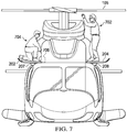
- Figure 7 illustrates a front view of an example rotorcraft having an example fairing on each side of the rotorcraft.
- the fairing 204 rests on the maintenance platform 208.
- the fairing 202 rests on the maintenance platform 207.
- Each of the fairings 202 and 204 is a work platform on which a maintenance person can work while the fairings 202 and 204 are in the open position.
- a foot traffic load applied to each of the fairings 202 and 204 comprises the weight of a person.
- Each fairing can support a load equal to or greater than the full weight of one or more people stepping on its surface.
- the load for a person stepping on the fairing may be estimated based on a 200-pound person and multiplied by a safety factor of about 2.0 or 3.0 (e.g., to account for an impulse load (dynamic loading) created by the person actively stepping or walking on the surface).
- the load is applied in an area estimated based on a size of the person's foot (e.g., 3-inch square area, or 9 in 2 ).
- a size of the person's foot e.g., 3-inch square area, or 9 in 2 .
- the load is 400 pounds in a 3-inch square area, or about 44.4 pounds per square inch (psi).
- the safety factor of 3.0 the load is 600 pounds in a 3-inch square area, or about 66.7 psi.
- the fairing can, advantageously, support at least 66.7 psi (i.e., applied over any 3-inch square area of its surface) or a 6001b point load (applied at any point on its surface).
- the fairing 202 is in the open position, which exposes a compartment in which a person 704 is working and has placed a tool bag 706.
- the person 704 and the tool bag 706 are a foot traffic load applied to the fairing 202.
- the fairing 204 is in the open position, which exposes the inner surface upon which a second person 702 stands to access the rotors 105. By standing on the fairing 204, the person 704 applies a foot traffic load to the fairing 204.
- some components may be implemented separately, consolidated into one or more integrated components, and/or omitted.
- methods associated with certain embodiments may be implemented using more, less, and/or other steps than those described herein, and their steps may be performed in any suitable order.
Landscapes
- Engineering & Computer Science (AREA)
- Aviation & Aerospace Engineering (AREA)
- Mechanical Engineering (AREA)
- Laminated Bodies (AREA)
- Bridges Or Land Bridges (AREA)
Abstract
Description
- This disclosure relates generally to aircraft fairings and cowlings, and more particularly, though not exclusively, to cable-free, strut-free, and moveable aircraft fairings and cowlings for supporting a person.
- An outer mold line (OML) provides an aerodynamic path for air to flow around the aircraft during flight and generally comprises an outer surface of an aircraft. The OML is an aerodynamic outer surface of aircraft that reduces aerodynamic drag. The OML comprises many contiguous surfaces of different components and/or fairings. Fairings and cowlings provide a relatively smooth outer surface that reduces aerodynamic drag experienced by the aircraft. For example, some rotorcrafts include fairing assemblies configured to protect propulsion related components and/or drivetrain components (e.g., driveshaft, gearbox, transmission system, and the like). For example, a fairing may be used for general drag reduction, but also for providing an aerodynamic flow path from the exterior of the fairing assembly to the engine inlet engine as well as for decorative purposes. Fairings and cowlings have, in the past, been constructed of aluminum or other light-weight metals, but are more recently increasingly constructed from composite materials, such as carbon fiber reinforced polymer (CFRP). In some rotorcraft configurations, drivetrain components are arranged in a compartment underneath the fairing. The components in the compartment require access, e.g., for occasional or periodic inspection and maintenance which necessitates at least partial removal of the fairing.
- According to one aspect of the present disclosure, a fairing for a rotorcraft includes a core material, an inner housing on a side of the core material, an outer housing on another side of the core material opposite the inner housing, and a hinge. The hinge is configured to move the fairing between an open position and a closed position. In the open position, the inner housing is configured to receive a foot traffic load while the outer housing is configured to transfer the foot traffic load to a fuselage of the rotorcraft. In the closed position, the inner housing is configured to stow in a compartment of the rotorcraft while the outer housing is configured to provide an outer mold line of the rotorcraft in the closed position.
- According to another aspect of the present disclosure, a rotorcraft comprises a fuselage, a fairing door assembly, and a hinge. The fuselage comprises an outer mold line of the rotorcraft. The fairing door assembly comprises a core material, an inner housing on a side of the core material, and an outer housing on another side of the core material opposite the inner housing. The fairing door assembly is configured to enable access to a compartment within the fuselage. The hinge is configured to move the fairing door assembly between an open position and a closed position. The inner housing is configured to receive a foot traffic load in the open position and to stow in the compartment in the closed position. The outer housing is configured to transfer the foot traffic load to the fuselage in the open position and to provide a portion of the outer mold line in the closed position.
-
-
Figures 1A and 1B illustrate an example embodiment of a rotorcraft in accordance with certain embodiments. -
Figure 2 illustrates an isometric view of an example fairing in a closed position. -
Figure 3 illustrates an isometric view of the example fairing ofFigure 2 in an open position. -
Figure 4 illustrates a cross section of the example fairing ofFigure 2 in the open position. -
Figure 5 illustrates a detailed cross section of a portion of the example fairing ofFigure 2 . -
Figure 6 illustrates a plan view a one side of the example fairing ofFigure 2 . -
Figure 7 illustrates a front view of an example rotorcraft having an example fairing on each side of the rotorcraft. - The following disclosure describes various illustrative embodiments and examples for implementing the features and functionality of the present disclosure. While particular components, arrangements, and/or features are described below in connection with various example embodiments, these are merely examples used to simplify the present disclosure and are not intended to be limiting. It will of course be appreciated that in the development of any actual embodiment, numerous implementation-specific decisions must be made to achieve the developer's specific goals, including compliance with system, business, and/or legal constraints, which may vary from one implementation to another. Moreover, it will be appreciated that, while such a development effort might be complex and time-consuming, it would nevertheless be a routine undertaking for those of ordinary skill in the art having the benefit of this disclosure.
- In the specification, reference may be made to the spatial relationships between various components and to the spatial orientation of various aspects of components as depicted in the attached drawings. However, as will be recognized by those skilled in the art after a complete reading of the present disclosure, the devices, components, members, apparatuses, etc. described herein may be positioned in any desired orientation. Thus, the use of terms such as "above," "below," "upper," "lower," or other similar terms to describe a spatial relationship between various components or to describe the spatial orientation of aspects of such components, should be understood to describe a relative relationship between the components or a spatial orientation of aspects of such components, respectively, as the components described herein may be oriented in any desired direction.
- Further, the present disclosure may repeat reference numerals and/or letters in the various examples. This repetition is for the purpose of simplicity and clarity and does not in itself dictate a relationship between the various embodiments and/or configurations discussed.
- Example embodiments that may be used to implement the features and functionality of this disclosure will now be described with more particular reference to the attached Figures.
-
Figures 1A and 1B illustrate an example embodiment of arotorcraft 101.Figure 1A illustrates a side view of therotorcraft 101, whileFigure 1B illustrates a perspective view of therotorcraft 101. Rotorcraft 101 includes arotor system 103 with a plurality ofrotor blades 105. The pitch of eachrotor blade 105 can be managed or adjusted in order to selectively control direction, thrust, and lift of therotorcraft 101. Rotorcraft 101 further includes afuselage 107, tail rotor oranti-torque system 109, anempennage 111, and atail structure 120. In the illustrated embodiment,tail structure 120 may be used as a horizontal stabilizer. Torque is supplied torotor system 103 andanti-torque system 109 using at least one engine. Therotorcraft 101 includes a variety of fairing and/or cowling assemblies configured to cover or protect components of the rotorcraft and reduce aerodynamic drag. One exampleupper cowling assembly 113 is arranged above an unillustrated engine and may, at least in part, cover and protect, for example, drivetrain components. Fairings and cowlings provide a relatively smooth outer surface that reduces aerodynamic drag experienced by therotorcraft 101. The terms "cowling" and "fairing" are used interchangeably in the present disclosure. - It should be appreciated that the
rotorcraft 101 ofFigures 1A and 1B are merely illustrative of a variety of aircraft that can be used to implement embodiments of the present disclosure. Other aircraft implementations can include, for example, tiltrotor aircraft, fixed wing airplanes, hybrid aircraft, unmanned aircraft, gyrocopters, a variety of helicopter configurations, and drones, among other examples. Moreover, it should be appreciated that even though aircraft are particularly well suited to implement embodiments of the present disclosure, the described embodiments can also be implemented using non-aircraft vehicles and devices. - Some fairings provide access to components in a compartment of a rotorcraft. In many rotorcraft, these fairings open vertically. For example, such fairings open in an upward direction (e.g., a hinge at the top of the fairing allows its bottom edge to swing up) to prevent having loads applied to it (e.g., to prevent people from placing objects on it or standing on it). A strut may be used to support the free edge of the fairing while it is open. Alternatively, the fairings open in a downward direction (e.g., a hinge at the bottom of the fairing allows its top edge to swing down). Commonly, a cable, a chain, or other tension member supports the free edge of the fairing while it is open; however, a strut (or other compression member) may be used to support the free edge of the fairing as an alternative. The supports (i.e., the tension or compression members) also prevent the fairing from over-opening. Although these fairings open downward and, therefore, provide a surface that could potentially support a load, they are often not capable of supporting such loads. Indeed, many of these fairings are conspicuously marked with indicia that indicates that, when the fairing is open, objects should not be placed on the fairing and, in addition, people should not step or stand on them. Such fairings are not a platform for walking, standing, working, or placing objects. Moreover, even if a person were to stand or walk on such a fairing, the supports are a trip hazard that could cause injury to the person. In addition, because these fairings are adjacent to the compartment (i.e., reveal a compartment underneath when open) and obstruct access to the compartment, there is a natural tendency (e.g., for maintenance people) to step on (or otherwise bear some of their weight on) the fairing in order to access the compartment, though doing so is hazardous.
- A solution disclosed herein is a cable-free, strut-free, and moveable fairing for supporting a person (e.g., weight of a person, load resulting from foot traffic, and the like).
- The embodiments described throughout this disclosure address the above challenges (and others) and provide numerous technical advantages, including simultaneously providing (1) access to a compartment of a rotorcraft and (2) a platform configured to support walking, standing, working, and/or placing objects. Moreover, the access and platform are provided without the use of tension members (e.g., cables or chains) and without the use of compression members (e.g., struts) to support the edges of the fairing. Instead, these supports (i.e., the tension members and the compression members) are replaced by hinges and a bearing surface (bearing on a surface under the fairing in the open position) that create a moment couple to support the foot traffic loads on the fairing. In other words, the combination of the hinges and bearing surface support the entire weight of the fairing and loads applied to the fairing and transfer forces (i.e., the weight and applied loads) to the fuselage. No other points of contact (such as is the case for tension members and compression members) are used to transfer the forces to the fuselage of the aircraft. Removing these supports advantageously eliminates significant trip hazards from the fairing that could cause injury to people who access the compartment by stepping on the fairing. Advantageously, because the fairing can support loads resulting from foot traffic (i.e., foot traffic loads), people can stand/squat on the fairing to access not only the compartment but also other components that are accessibly by standing on the fairing (e.g., overhead objects that are only accessible from the platform when standing). For example, people can squat on the fairing to access a gearbox in the compartment and can also stand on the fairing to access rotors above the fairing. While the rotorcraft may have other (relatively small) maintenance platforms on which a person can stand to access components of the rotorcraft, the surface area of the fairing advantageously provides a larger work area on which to move around (e.g., relative to the other maintenance platforms). Using the larger work area can increase the speed of repairs and maintenance on the rotorcraft.
- Example embodiments that may be used to implement cable-free, strut-free, and moveable fairings for supporting a person are described below with more particular reference to the remaining Figures.
-
Figures 2 and3 illustrate isometric views of a portion of therotorcraft 101 below thefairing assembly 113. Therotorcraft 101 comprises, on each of two sides, a maintenance platform and a cable-free, strut-free, and moveable fairing for supporting a person. Amaintenance platform 208 is shown inFigures 2 and3 . Another maintenance platform 207 (which is illustrated inFigure 7 ) is located on an opposite side of therotorcraft 101. Each of the fairings can operate as a door to selectively enclose or reveal (e.g., based on being in a closed position or in an open position, respectively) acompartment 218 withinrotorcraft 101. In this particular example, thecompartment 218 encloses areduction gearbox 302, which provides reduction gearing to a driveshaft assembly. The views depicted inFigures 2 and3 , illustrate one of the two example fairings (i.e., example fairing 204).Figure 2 illustrates the fairing 204 in the closed position.Figure 3 illustrates the fairing 204 in the open position. Another fairing 202 (which is illustrated inFigure 7 ) is located on an opposite side of therotorcraft 101. It is noted that the twofairings Figure 7 ). Thus, the details described below with respect to the fairing 204 are equally applicable to thefairing 202. - The following description of the fairing 204 is provided with simultaneous reference to
Figures 2 and3 . In general, the fairing 204 comprises a core material, aninner housing 216, and anouter housing 214. Theinner housing 216 is on an inside of the core material. Theouter housing 214 is on an outside of the core material, opposite theinner housing 216. A raisedportion 206 extends from theouter housing 214. The core material, theinner housing 216, and theouter housing 214, at least in part, define a door, which can selectively enclose or reveal thecompartment 218. A hinge pivotally couples the fairing 204 to a fuselage of the rotorcraft and enables the fairing 204 to pivot between the open position and the closed position. A releasable locking mechanism secures the fairing 204 to an adjacent fairing in the closed position. In the example shown inFigures 2 and3 , one releasable locking mechanism comprises latchingcomponents components fairing 204. Each of the latchingcomponents trigger latch 211a is at a forward edge of thefairing 204 and triggerlatch 211b is at an aft edge of thefairing 204. The trigger latches 211a and 211b secure the fairing 204 to the edge of the adjacent fairing and release thefairing 204 when a trigger portion of the latch is pulled. - Now turning to
Figure 2, Figure 2 illustrates the fairing 204 in the closed position. The fairing 204 encloses thecompartment 218 and, therefore, thecompartment 218 is hidden from view. In the closed position, the latchingcomponents components inner housing 216 is stowed in thecompartment 218 while theouter housing 214 provides a portion of an outer mold line of the rotorcraft. - Now turning to
Figure 3, Figure 3 illustrates an isometric view of the example fairing ofFigure 2 in the open position. In the open position, the fairing 204 exposes thecompartment 218 and, therefore, provides access to components in thecompartment 218 such as thereduction gearbox 302. The latchingcomponents components inner housing 216 is configured to receive a foot traffic load in the open position and theouter housing 214 is configured to transfer the foot traffic load to the fuselage of the rotorcraft. In particular, the raisedportion 206 is attached to the exposed surface of theouter housing 214. When the fairing 204 is in the open position, the raisedportion 206 contacts themaintenance platform 208 and transfers the foot traffic load to the fuselage via the maintenance platform 208 (described further with respect toFigures 4 ,5, and 6 ). Theinner housing 216 provides a platform for walking, standing, and/or working. For example, maintenance people can work from the fairing 204 to perform maintenance on the rotorcraft. While a person may stand on themaintenance platform 208, the exposed surface of theinner housing 216 provides a larger work area on which to move around (e.g., relative to the maintenance platform 208). Using the larger work area can increase the speed of repairs and maintenance on the rotorcraft. -
Figure 4 illustrates a cross section of the fairing 204 in the open position ofFigure 3 . The cross section ofFigure 4 is cut along a line as generally indicated by the lines labeled "4" inFigure 3 . Many of the components of thefairing 204 and the rotorcraft are described above and are not repeat here only for brevity. Theinner housing 216 and theouter housing 214 are offset from one another. In this example,inner housing 216 and theouter housing 214 substantially parallel along a portion of the fairing 204and curve to contact one another along another portion of thefairing 204.Figure 4 illustrates that themaintenance platform 208 is attached to thefuselage 107. Ahinge 402b is one of multiple hinges that attach the fairing 204 to thefuselage 107. Each of the hinges is configured to move the fairing between the open position (e.g., as depicted inFigure 3 ) and the closed position (e.g., as depicted inFigure 2 ). The raisedportion 206 is attached to theouter housing 214. In addition, the raisedportion 206 bears directly on a top surface of themaintenance platform 208 and, thereby, can transfer the foot traffic load from the fairing 204 to thefuselage 107. The raisedportion 206 only bears on themaintenance platform 208 when the fairing 204 is in the open position. When the fairing 204 is in the closed position, the raisedportion 206 does not contact themaintenance platform 208. Foot traffic loading on the fairing 204 (e.g., when a person steps and/or walks on theinner housing 216 in the open position) causes reaction forces at the hinges and the raisedportion 206 bearing on themaintenance platform 208. For example, one reaction force is generated at the hinges (e.g.,hinge 402b) and another reaction force is generated at a center of the bearingportion 206.Length 408 is measured between thehinge 402b and the center of the bearingportion 206. These reaction forces form a moment couple (e.g., where the forces are separated by a moment arm distance equal to the length 408) to transfer the foot traffic load to thefuselage 107. This moment couple formed by the hinge and the raisedportion 206 support all of the foot traffic load applied to thefairing 204. In other words, only the hinges and the raisedportion 206 support the foot traffic load and no other points of contact (i.e., no cables or struts) are used to transfer the foot traffic load to thefuselage 107. Removing supports such as cables and struts advantageously eliminates significant trip hazards from the fairing 204 that could cause injury to people who access thecompartment 218 by stepping on thefairing 204.Length 410 is a length of thefairing 204 and is measured between thehinge 402b and a distal edge of the fairing 204 with respect to thefuselage 107. In this example, a ratio of thelength 408 to thelength 410 is 5 to 1.Length 412 is a length of a work surface of thefairing 204 and is measured between thehinge 402b and a distal edge of a flat top surface of the fairing 204 with respect to thefuselage 107. In addition, the work surface provided by the fairing 204 increases the available area on which a maintenance person can work relative to themaintenance platform 208 by about 3X (e.g., ratio of thelength 408 to thelength 412 is about 3 to 1). -
Figure 5 illustrates a detailed cross section of a portion of the cross section ofFigure 4 . The cross section ofFigure 5 is a detailed view of the portion of the cross section ofFigure 4 as generally indicated by the circle labeled "FIG. 5 " inFigure 4 . Athickness 506 is measured between a face of theinner housing 216 and a face of theouter housing 214. Acore material 502 contributes to the stiffness of thefairing 204. For example, thecore material 502 may comprise a corrugated material, which has high stiffness due to its corrugations. Thecore material 502 is a different material than the housings (i.e., theinner housing 216 and the outer housing 214). For example, each of theinner housing 216 and theouter housing 214 can comprise carbon fiber reinforced polymer and/or a metal (as is describer further below). - The
inner housing 216 is attached to one side of thecore material 502. Theouter housing 214 is attached to another side of thecore material 502 opposite theinner housing 216. Theinner housing 216 and theouter housing 214 enclose thecore material 502. For example, the fairing 204 may be manufactured using sandwich core construction for ease of manufacturing. In addition, further stiffeners (e.g., beams, spars, ribs, and the like) can be embedded in thecore material 502 to further increase the stiffness of thefairing 204. The raisedpotion 206 is attached to theouter housing 214 by the fasteners 504 (e.g., 504a and 504b). In some embodiments, the raisedpotion 206 is a planar material that is formed into a raised shape. For example, the raisedpotion 206 may be sheet metal (e.g., fractions of an inch thick, 1/8 inch) that is formed into the raised shape by a hydroforming process or mechanical press. The raisedportion 206 is raised relative to theouter housing 214 by alength 508.Length 510 is a width of an area of contact between the raisedportion 206 and themaintenance platform 208. A length of the area of contact between the raisedportion 206 and themaintenance platform 208 is illustrated inFigure 6 . The area of contact distributes foot traffic loads across an equivalent area of themaintenance platform 208. In general, increasing the area of contact reduces the stress (e.g., load per unit area) imposed on the maintenance platform 208 (i.e., given a constant loading). Likewise, reducing the area of contact increases the stress imposed on themaintenance platform 208. - Each of the
inner housing 216 and theouter housing 214 may be made of a metal, such as steel or aluminum, or a metal alloy, such as an aluminum alloy. Alternatively, theinner housing 216 and theouter housing 214 may be made of a nonmetallic material, such as reinforced plastics and advanced composites (e.g., carbon fiber reinforced polymer (CFRP)). Carbon fiber reinforced polymers have the advantage of high strength-to-weight ratio, modulus (stiffness to density ratio) 3.5 to 5 times that of steel or aluminum, longer life than metals, higher corrosion resistance,tensile strength 4 to 6 times that of steel or aluminum, and greater design flexibility. Furthermore, the bonded construction of composites such as CFRP can reduce the number joints and fasteners for each component, making these components easy to repair. Accordingly, theinner housing 216 and theouter housing 214 being constructed from composites will be lighter and, in spite of the reduced weight, will be stronger than comparable components made from aluminum alloys and other metals. -
Figure 6 illustrates a plan view of an outer side of thefairing 204. The raisedportion 206 is attached to theouter surface 214 by a plurality offasteners 504. Each of the latchingcomponents fairing 204.Length 410 is the length of thefairing 204.Figure 6 illustrates themultiple hinges length 602 is a width of thefairing 204. In a particular example, thelength 408 is about 5.5 inches on average (e.g., varying between the front and aft ends), thelength 410 is about 27.4 inches on average (e.g., varying between the front and aft ends), thelength 412 is about 18 inches on average (e.g., varying from about 16.6 inches at the front end to about 19.4 inches at the aft end), thelength 602 is about 65 inches, thelength 604 is about 55 inches, thelength 510 is about 2.6 inches, the length 508 (illustrated inFigure 5 ) is about 0.27 inches on average (e.g., varying from about .40 inches at the front end to about 0.15 inches at the aft end), and the thickness 506 (illustrated inFigure 5 ) is about 2 inches on average (e.g., varying from about 1.9 inches at the front end to about 2.1 inches at the aft end. -
Figure 7 illustrates a front view of an example rotorcraft having an example fairing on each side of the rotorcraft. The fairing 204 rests on themaintenance platform 208. The fairing 202 rests on themaintenance platform 207. Each of thefairings fairings fairings person 704 is working and has placed atool bag 706. Theperson 704 and thetool bag 706 are a foot traffic load applied to thefairing 202. The fairing 204 is in the open position, which exposes the inner surface upon which asecond person 702 stands to access therotors 105. By standing on thefairing 204, theperson 704 applies a foot traffic load to thefairing 204. - Although several embodiments have been illustrated and described in detail, numerous other changes, substitutions, variations, alterations, and/or modifications are possible without departing from the spirit and scope of the present invention, as defined by the appended claims. The particular embodiments described herein are illustrative only, and may be modified and practiced in different but equivalent manners, as would be apparent to those of ordinary skill in the art having the benefit of the teachings herein. Those of ordinary skill in the art would appreciate that the present disclosure may be readily used as a basis for designing or modifying other embodiments for carrying out the same purposes and/or achieving the same advantages of the embodiments introduced herein. For example, certain embodiments may be implemented using more, less, and/or other components than those described herein. Moreover, in certain embodiments, some components may be implemented separately, consolidated into one or more integrated components, and/or omitted. Similarly, methods associated with certain embodiments may be implemented using more, less, and/or other steps than those described herein, and their steps may be performed in any suitable order.
- Numerous other changes, substitutions, variations, alterations, and modifications may be ascertained to one of ordinary skill in the art and it is intended that the present disclosure encompass all such changes, substitutions, variations, alterations, and modifications as falling within the scope of the appended claims.
Claims (11)
- A fairing comprising:a core material;an inner housing on a side of the core material;an outer housing on another side of the core material opposite the inner housing;a hinge configured to move the fairing between an open position and a closed position;wherein the inner housing is configured to receive a foot traffic load in the open position and to stow in a compartment of a rotorcraft in the closed position; andwherein the outer housing is configured to transfer the foot traffic load to a fuselage of the rotorcraft in the open position and to provide a portion of an outer mold line of the rotorcraft in the closed position.
- A rotorcraft comprising:a fuselage comprising an outer mold line;a fairing door assembly configured to enable access to a compartment within the fuselage, the fairing door assembly comprising:a core material;an inner housing on a side of the core material;an outer housing on another side of the core material opposite the inner housing;a hinge configured to move the fairing door assembly between an open position and a closed position;wherein the inner housing is configured to receive a foot traffic load in the open position and to stow in the compartment in the closed position; andwherein the outer housing is configured to transfer the foot traffic load to the fuselage in the open position and to provide a portion of the outer mold line in the closed position.
- The fairing of claim 1 or the rotorcraft of claim 2, wherein the core material, the inner housing, and the outer housing, at least in part, define a door.
- The fairing of claim 1 or of claim 3, or the rotorcraft of claim 2 or of claim 3, further comprising:a raised portion extended from the outer housing, wherein the raised portion is configured to contact the fuselage and to transfer the foot traffic load to the fuselage.
- The fairing or rotorcraft of claim 4, wherein the hinge is configured to attach the fairing to the fuselage.
- The fairing or rotorcraft of claim 5, wherein the hinge and the raised portion are configured to form a moment couple to transfer the foot traffic load to the fuselage.
- The fairing or rotorcraft of claim 6, wherein the moment couple formed by the hinge and the raised portion support all of the foot traffic load;
wherein only the hinge and the raised portion support the foot traffic load - The fairing of claim 1 or of any preceding fairing claim, or the rotorcraft of claim 2 or of any preceding rotorcraft claim, wherein the fairing is configured to extend out from the fuselage in the open position; and wherein
a first length is measured between the hinge and a distal edge of the fairing with respect to the fuselage,
a second length is measured between the hinge and a center of the raised portion, and
a ratio of the first length to the second length is 5 to 1. - The fairing of claim 1 or of any preceding fairing claim, or the rotorcraft of claim 2 or of any preceding rotorcraft claim, wherein the core material comprises a corrugated material.
- The fairing of claim 1 or of any preceding fairing claim, or the rotorcraft of claim 2 or of any preceding rotorcraft claim, wherein the foot traffic load comprises 600 pounds applied at any point on the inner housing of the fairing.
- The fairing of claim 1 or of any preceding fairing claim, or the rotorcraft of claim 2 or any preceding rotorcraft claim, wherein each of the inner housing and the outer housing comprises carbon fiber reinforced polymer and/or a metal plate.
Applications Claiming Priority (1)
| Application Number | Priority Date | Filing Date | Title |
|---|---|---|---|
| US15/684,628 US10661880B2 (en) | 2017-08-23 | 2017-08-23 | Cable-free and strut-free fairing for supporting a person |
Publications (2)
| Publication Number | Publication Date |
|---|---|
| EP3446967A1 true EP3446967A1 (en) | 2019-02-27 |
| EP3446967B1 EP3446967B1 (en) | 2019-08-28 |
Family
ID=60037429
Family Applications (1)
| Application Number | Title | Priority Date | Filing Date |
|---|---|---|---|
| EP17195081.9A Active EP3446967B1 (en) | 2017-08-23 | 2017-10-05 | Cable-free and strut-free fairing for supporting a person |
Country Status (2)
| Country | Link |
|---|---|
| US (1) | US10661880B2 (en) |
| EP (1) | EP3446967B1 (en) |
Cited By (1)
| Publication number | Priority date | Publication date | Assignee | Title |
|---|---|---|---|---|
| US10661880B2 (en) | 2017-08-23 | 2020-05-26 | Bell Helicopter Textron Inc. | Cable-free and strut-free fairing for supporting a person |
Families Citing this family (4)
| Publication number | Priority date | Publication date | Assignee | Title |
|---|---|---|---|---|
| US10875657B2 (en) | 2017-09-15 | 2020-12-29 | Bell Helicopter Textron Inc. | Hold open j-track locking mechanism for cowling |
| US10875656B2 (en) * | 2017-09-15 | 2020-12-29 | Bell Helicopter Textron Inc. | Bi-folding engine cowl having a plurality of open positions to provide access |
| US20230210253A1 (en) * | 2022-01-05 | 2023-07-06 | Bell Textron Inc. | Work platform system |
| US12662233B2 (en) * | 2022-01-05 | 2026-06-23 | Textron Innovations Inc. | Folding step system |
Citations (3)
| Publication number | Priority date | Publication date | Assignee | Title |
|---|---|---|---|---|
| FR2174690A1 (en) * | 1972-03-07 | 1973-10-19 | Aerospatiale | |
| US6126114A (en) * | 1997-09-12 | 2000-10-03 | Eurocopter | Door for aircraft, particularly for helicopter, with interconnected movements of upper and lower leaves |
| EP3050794A1 (en) * | 2015-01-28 | 2016-08-03 | AIRBUS HELICOPTERS DEUTSCHLAND GmbH | Aircraft with inwardly foldable rear door |
Family Cites Families (3)
| Publication number | Priority date | Publication date | Assignee | Title |
|---|---|---|---|---|
| US4910065A (en) * | 1987-10-15 | 1990-03-20 | The Boeing Company | Reinforced honeycomb core sandwich panels and method for making same |
| US10384399B2 (en) * | 2016-03-08 | 2019-08-20 | The Boeing Company | Systems and methods for depositing compounds in a structure |
| US10661880B2 (en) | 2017-08-23 | 2020-05-26 | Bell Helicopter Textron Inc. | Cable-free and strut-free fairing for supporting a person |
-
2017
- 2017-08-23 US US15/684,628 patent/US10661880B2/en active Active
- 2017-10-05 EP EP17195081.9A patent/EP3446967B1/en active Active
Patent Citations (3)
| Publication number | Priority date | Publication date | Assignee | Title |
|---|---|---|---|---|
| FR2174690A1 (en) * | 1972-03-07 | 1973-10-19 | Aerospatiale | |
| US6126114A (en) * | 1997-09-12 | 2000-10-03 | Eurocopter | Door for aircraft, particularly for helicopter, with interconnected movements of upper and lower leaves |
| EP3050794A1 (en) * | 2015-01-28 | 2016-08-03 | AIRBUS HELICOPTERS DEUTSCHLAND GmbH | Aircraft with inwardly foldable rear door |
Non-Patent Citations (2)
| Title |
|---|
| ANONYMOUS: "Mil Mi-26 Helicopter, human for scale", 12 July 2016 (2016-07-12), XP055442757, Retrieved from the Internet <URL:https://imgur.com/gallery/LfHjuPZ> [retrieved on 20180119] * |
| ZKYT MILITARY NEWS: "Mil Mi-26 Soviet/Russian heavy transport helicopter", 19 July 2017 (2017-07-19), XP054978048, Retrieved from the Internet <URL:https://www.youtube.com/watch?v=NPkAHMGN4Ts> [retrieved on 20180119] * |
Cited By (1)
| Publication number | Priority date | Publication date | Assignee | Title |
|---|---|---|---|---|
| US10661880B2 (en) | 2017-08-23 | 2020-05-26 | Bell Helicopter Textron Inc. | Cable-free and strut-free fairing for supporting a person |
Also Published As
| Publication number | Publication date |
|---|---|
| US10661880B2 (en) | 2020-05-26 |
| US20190061902A1 (en) | 2019-02-28 |
| EP3446967B1 (en) | 2019-08-28 |
Similar Documents
| Publication | Publication Date | Title |
|---|---|---|
| EP3446967B1 (en) | Cable-free and strut-free fairing for supporting a person | |
| Mouritz | Introduction to aerospace materials | |
| CN107933888B (en) | Aircraft wing, aircraft, and related methods | |
| EP3418183A1 (en) | Two position cowling assembly for single person operation | |
| US10227127B2 (en) | Fiber metal laminate reinforced wing spar for retractable underwing mounted landing gear assemblies | |
| US20160375979A1 (en) | Aircraft structural component that is adapted for absorbing and transmitting forces in an aircraft | |
| CN109080813B (en) | Wing-to-fuselage junction and aircraft including the same | |
| CN115535211A (en) | Aircraft and method of manufacturing aircraft | |
| US10766628B2 (en) | Air inlet with integrated structural hand hold | |
| EP3360784A1 (en) | Composite fan cowl with a core having tailored thickness | |
| CN110077585B (en) | Multi-rotor aircraft | |
| WO2008103735A2 (en) | Aircraft, and retrofit components therefor | |
| US10882602B2 (en) | Fairing edge handhold | |
| EP3945017B1 (en) | Bead-stiffened movable surfaces | |
| EP3403919B1 (en) | Cowling with structural hand holds operating also as maintenance position bumpers | |
| US10752332B2 (en) | Fairing integrating with outer mold line and protective portions | |
| Paul et al. | History of flight vehicle structures 1903-1990 | |
| US10875657B2 (en) | Hold open j-track locking mechanism for cowling | |
| US10745106B2 (en) | Step handhold and support | |
| CN103534168A (en) | Body of a multi-mode high maneuverability aircraft | |
| Sadraey | Structural Design | |
| US20050178883A1 (en) | Helicopter tail rotor pylon | |
| US20240317382A1 (en) | Beaded composite structural web | |
| García | THE RACER: MANUFACTURING AND TESTING Axel Fink, axel. fink@ airbus. com, AIRBUS Helicopters (Germany) Martin Blacha, martin. blacha@ airbus. com, AIRBUS Helicopters (Germany) Richard Miles, Richard. Miles@ hambleaero. com, Hamble Aerostructures,(UK) | |
| Watson | Preliminary design development AV-8B forward fuselage composite structure |
Legal Events
| Date | Code | Title | Description |
|---|---|---|---|
| STAA | Information on the status of an ep patent application or granted ep patent |
Free format text: STATUS: EXAMINATION IS IN PROGRESS |
|
| PUAI | Public reference made under article 153(3) epc to a published international application that has entered the european phase |
Free format text: ORIGINAL CODE: 0009012 |
|
| 17P | Request for examination filed |
Effective date: 20171005 |
|
| AK | Designated contracting states |
Kind code of ref document: A1 Designated state(s): AL AT BE BG CH CY CZ DE DK EE ES FI FR GB GR HR HU IE IS IT LI LT LU LV MC MK MT NL NO PL PT RO RS SE SI SK SM TR |
|
| AX | Request for extension of the european patent |
Extension state: BA ME |
|
| GRAP | Despatch of communication of intention to grant a patent |
Free format text: ORIGINAL CODE: EPIDOSNIGR1 |
|
| STAA | Information on the status of an ep patent application or granted ep patent |
Free format text: STATUS: GRANT OF PATENT IS INTENDED |
|
| INTG | Intention to grant announced |
Effective date: 20190415 |
|
| GRAS | Grant fee paid |
Free format text: ORIGINAL CODE: EPIDOSNIGR3 |
|
| GRAA | (expected) grant |
Free format text: ORIGINAL CODE: 0009210 |
|
| STAA | Information on the status of an ep patent application or granted ep patent |
Free format text: STATUS: THE PATENT HAS BEEN GRANTED |
|
| AK | Designated contracting states |
Kind code of ref document: B1 Designated state(s): AL AT BE BG CH CY CZ DE DK EE ES FI FR GB GR HR HU IE IS IT LI LT LU LV MC MK MT NL NO PL PT RO RS SE SI SK SM TR |
|
| REG | Reference to a national code |
Ref country code: GB Ref legal event code: FG4D |
|
| REG | Reference to a national code |
Ref country code: CH Ref legal event code: EP |
|
| REG | Reference to a national code |
Ref country code: AT Ref legal event code: REF Ref document number: 1172079 Country of ref document: AT Kind code of ref document: T Effective date: 20190915 |
|
| REG | Reference to a national code |
Ref country code: IE Ref legal event code: FG4D |
|
| REG | Reference to a national code |
Ref country code: DE Ref legal event code: R096 Ref document number: 602017006510 Country of ref document: DE |
|
| REG | Reference to a national code |
Ref country code: NL Ref legal event code: MP Effective date: 20190828 |
|
| REG | Reference to a national code |
Ref country code: LT Ref legal event code: MG4D |
|
| PG25 | Lapsed in a contracting state [announced via postgrant information from national office to epo] |
Ref country code: NO Free format text: LAPSE BECAUSE OF FAILURE TO SUBMIT A TRANSLATION OF THE DESCRIPTION OR TO PAY THE FEE WITHIN THE PRESCRIBED TIME-LIMIT Effective date: 20191128 Ref country code: FI Free format text: LAPSE BECAUSE OF FAILURE TO SUBMIT A TRANSLATION OF THE DESCRIPTION OR TO PAY THE FEE WITHIN THE PRESCRIBED TIME-LIMIT Effective date: 20190828 Ref country code: PT Free format text: LAPSE BECAUSE OF FAILURE TO SUBMIT A TRANSLATION OF THE DESCRIPTION OR TO PAY THE FEE WITHIN THE PRESCRIBED TIME-LIMIT Effective date: 20191230 Ref country code: NL Free format text: LAPSE BECAUSE OF FAILURE TO SUBMIT A TRANSLATION OF THE DESCRIPTION OR TO PAY THE FEE WITHIN THE PRESCRIBED TIME-LIMIT Effective date: 20190828 Ref country code: SE Free format text: LAPSE BECAUSE OF FAILURE TO SUBMIT A TRANSLATION OF THE DESCRIPTION OR TO PAY THE FEE WITHIN THE PRESCRIBED TIME-LIMIT Effective date: 20190828 Ref country code: BG Free format text: LAPSE BECAUSE OF FAILURE TO SUBMIT A TRANSLATION OF THE DESCRIPTION OR TO PAY THE FEE WITHIN THE PRESCRIBED TIME-LIMIT Effective date: 20191128 Ref country code: HR Free format text: LAPSE BECAUSE OF FAILURE TO SUBMIT A TRANSLATION OF THE DESCRIPTION OR TO PAY THE FEE WITHIN THE PRESCRIBED TIME-LIMIT Effective date: 20190828 Ref country code: LT Free format text: LAPSE BECAUSE OF FAILURE TO SUBMIT A TRANSLATION OF THE DESCRIPTION OR TO PAY THE FEE WITHIN THE PRESCRIBED TIME-LIMIT Effective date: 20190828 |
|
| PG25 | Lapsed in a contracting state [announced via postgrant information from national office to epo] |
Ref country code: AL Free format text: LAPSE BECAUSE OF FAILURE TO SUBMIT A TRANSLATION OF THE DESCRIPTION OR TO PAY THE FEE WITHIN THE PRESCRIBED TIME-LIMIT Effective date: 20190828 Ref country code: LV Free format text: LAPSE BECAUSE OF FAILURE TO SUBMIT A TRANSLATION OF THE DESCRIPTION OR TO PAY THE FEE WITHIN THE PRESCRIBED TIME-LIMIT Effective date: 20190828 Ref country code: RS Free format text: LAPSE BECAUSE OF FAILURE TO SUBMIT A TRANSLATION OF THE DESCRIPTION OR TO PAY THE FEE WITHIN THE PRESCRIBED TIME-LIMIT Effective date: 20190828 Ref country code: IS Free format text: LAPSE BECAUSE OF FAILURE TO SUBMIT A TRANSLATION OF THE DESCRIPTION OR TO PAY THE FEE WITHIN THE PRESCRIBED TIME-LIMIT Effective date: 20191228 Ref country code: GR Free format text: LAPSE BECAUSE OF FAILURE TO SUBMIT A TRANSLATION OF THE DESCRIPTION OR TO PAY THE FEE WITHIN THE PRESCRIBED TIME-LIMIT Effective date: 20191129 Ref country code: ES Free format text: LAPSE BECAUSE OF FAILURE TO SUBMIT A TRANSLATION OF THE DESCRIPTION OR TO PAY THE FEE WITHIN THE PRESCRIBED TIME-LIMIT Effective date: 20190828 |
|
| REG | Reference to a national code |
Ref country code: AT Ref legal event code: MK05 Ref document number: 1172079 Country of ref document: AT Kind code of ref document: T Effective date: 20190828 |
|
| PG25 | Lapsed in a contracting state [announced via postgrant information from national office to epo] |
Ref country code: TR Free format text: LAPSE BECAUSE OF FAILURE TO SUBMIT A TRANSLATION OF THE DESCRIPTION OR TO PAY THE FEE WITHIN THE PRESCRIBED TIME-LIMIT Effective date: 20190828 |
|
| PG25 | Lapsed in a contracting state [announced via postgrant information from national office to epo] |
Ref country code: RO Free format text: LAPSE BECAUSE OF FAILURE TO SUBMIT A TRANSLATION OF THE DESCRIPTION OR TO PAY THE FEE WITHIN THE PRESCRIBED TIME-LIMIT Effective date: 20190828 Ref country code: PL Free format text: LAPSE BECAUSE OF FAILURE TO SUBMIT A TRANSLATION OF THE DESCRIPTION OR TO PAY THE FEE WITHIN THE PRESCRIBED TIME-LIMIT Effective date: 20190828 Ref country code: DK Free format text: LAPSE BECAUSE OF FAILURE TO SUBMIT A TRANSLATION OF THE DESCRIPTION OR TO PAY THE FEE WITHIN THE PRESCRIBED TIME-LIMIT Effective date: 20190828 Ref country code: AT Free format text: LAPSE BECAUSE OF FAILURE TO SUBMIT A TRANSLATION OF THE DESCRIPTION OR TO PAY THE FEE WITHIN THE PRESCRIBED TIME-LIMIT Effective date: 20190828 Ref country code: EE Free format text: LAPSE BECAUSE OF FAILURE TO SUBMIT A TRANSLATION OF THE DESCRIPTION OR TO PAY THE FEE WITHIN THE PRESCRIBED TIME-LIMIT Effective date: 20190828 |
|
| PG25 | Lapsed in a contracting state [announced via postgrant information from national office to epo] |
Ref country code: CZ Free format text: LAPSE BECAUSE OF FAILURE TO SUBMIT A TRANSLATION OF THE DESCRIPTION OR TO PAY THE FEE WITHIN THE PRESCRIBED TIME-LIMIT Effective date: 20190828 Ref country code: IS Free format text: LAPSE BECAUSE OF FAILURE TO SUBMIT A TRANSLATION OF THE DESCRIPTION OR TO PAY THE FEE WITHIN THE PRESCRIBED TIME-LIMIT Effective date: 20200224 Ref country code: SM Free format text: LAPSE BECAUSE OF FAILURE TO SUBMIT A TRANSLATION OF THE DESCRIPTION OR TO PAY THE FEE WITHIN THE PRESCRIBED TIME-LIMIT Effective date: 20190828 Ref country code: MC Free format text: LAPSE BECAUSE OF FAILURE TO SUBMIT A TRANSLATION OF THE DESCRIPTION OR TO PAY THE FEE WITHIN THE PRESCRIBED TIME-LIMIT Effective date: 20190828 Ref country code: SK Free format text: LAPSE BECAUSE OF FAILURE TO SUBMIT A TRANSLATION OF THE DESCRIPTION OR TO PAY THE FEE WITHIN THE PRESCRIBED TIME-LIMIT Effective date: 20190828 |
|
| REG | Reference to a national code |
Ref country code: DE Ref legal event code: R097 Ref document number: 602017006510 Country of ref document: DE |
|
| PLBE | No opposition filed within time limit |
Free format text: ORIGINAL CODE: 0009261 |
|
| STAA | Information on the status of an ep patent application or granted ep patent |
Free format text: STATUS: NO OPPOSITION FILED WITHIN TIME LIMIT |
|
| PG2D | Information on lapse in contracting state deleted |
Ref country code: IS |
|
| PG25 | Lapsed in a contracting state [announced via postgrant information from national office to epo] |
Ref country code: LU Free format text: LAPSE BECAUSE OF NON-PAYMENT OF DUE FEES Effective date: 20191005 |
|
| 26N | No opposition filed |
Effective date: 20200603 |
|
| REG | Reference to a national code |
Ref country code: BE Ref legal event code: MM Effective date: 20191031 |
|
| PG25 | Lapsed in a contracting state [announced via postgrant information from national office to epo] |
Ref country code: BE Free format text: LAPSE BECAUSE OF NON-PAYMENT OF DUE FEES Effective date: 20191031 |
|
| PG25 | Lapsed in a contracting state [announced via postgrant information from national office to epo] |
Ref country code: IE Free format text: LAPSE BECAUSE OF NON-PAYMENT OF DUE FEES Effective date: 20191005 |
|
| PG25 | Lapsed in a contracting state [announced via postgrant information from national office to epo] |
Ref country code: CY Free format text: LAPSE BECAUSE OF FAILURE TO SUBMIT A TRANSLATION OF THE DESCRIPTION OR TO PAY THE FEE WITHIN THE PRESCRIBED TIME-LIMIT Effective date: 20190828 |
|
| REG | Reference to a national code |
Ref country code: CH Ref legal event code: PL |
|
| PG25 | Lapsed in a contracting state [announced via postgrant information from national office to epo] |
Ref country code: LI Free format text: LAPSE BECAUSE OF FAILURE TO SUBMIT A TRANSLATION OF THE DESCRIPTION OR TO PAY THE FEE WITHIN THE PRESCRIBED TIME-LIMIT Effective date: 20201031 Ref country code: CH Free format text: LAPSE BECAUSE OF FAILURE TO SUBMIT A TRANSLATION OF THE DESCRIPTION OR TO PAY THE FEE WITHIN THE PRESCRIBED TIME-LIMIT Effective date: 20201031 |
|
| PG25 | Lapsed in a contracting state [announced via postgrant information from national office to epo] |
Ref country code: HU Free format text: LAPSE BECAUSE OF FAILURE TO SUBMIT A TRANSLATION OF THE DESCRIPTION OR TO PAY THE FEE WITHIN THE PRESCRIBED TIME-LIMIT; INVALID AB INITIO Effective date: 20171005 Ref country code: MT Free format text: LAPSE BECAUSE OF FAILURE TO SUBMIT A TRANSLATION OF THE DESCRIPTION OR TO PAY THE FEE WITHIN THE PRESCRIBED TIME-LIMIT Effective date: 20190828 |
|
| PG25 | Lapsed in a contracting state [announced via postgrant information from national office to epo] |
Ref country code: SI Free format text: LAPSE BECAUSE OF FAILURE TO SUBMIT A TRANSLATION OF THE DESCRIPTION OR TO PAY THE FEE WITHIN THE PRESCRIBED TIME-LIMIT Effective date: 20190828 |
|
| PG25 | Lapsed in a contracting state [announced via postgrant information from national office to epo] |
Ref country code: MK Free format text: LAPSE BECAUSE OF FAILURE TO SUBMIT A TRANSLATION OF THE DESCRIPTION OR TO PAY THE FEE WITHIN THE PRESCRIBED TIME-LIMIT Effective date: 20190828 |
|
| P01 | Opt-out of the competence of the unified patent court (upc) registered |
Effective date: 20230602 |
|
| PGFP | Annual fee paid to national office [announced via postgrant information from national office to epo] |
Ref country code: DE Payment date: 20251029 Year of fee payment: 9 |
|
| PGFP | Annual fee paid to national office [announced via postgrant information from national office to epo] |
Ref country code: GB Payment date: 20251027 Year of fee payment: 9 |
|
| PGFP | Annual fee paid to national office [announced via postgrant information from national office to epo] |
Ref country code: IT Payment date: 20251021 Year of fee payment: 9 |
|
| PGFP | Annual fee paid to national office [announced via postgrant information from national office to epo] |
Ref country code: FR Payment date: 20251027 Year of fee payment: 9 |