EP3446790B1 - Trigger sprayer valve body with pass through filling path - Google Patents
Trigger sprayer valve body with pass through filling path Download PDFInfo
- Publication number
- EP3446790B1 EP3446790B1 EP18190036.6A EP18190036A EP3446790B1 EP 3446790 B1 EP3446790 B1 EP 3446790B1 EP 18190036 A EP18190036 A EP 18190036A EP 3446790 B1 EP3446790 B1 EP 3446790B1
- Authority
- EP
- European Patent Office
- Prior art keywords
- valve body
- container
- liquid
- pumping chamber
- head portion
- Prior art date
- Legal status (The legal status is an assumption and is not a legal conclusion. Google has not performed a legal analysis and makes no representation as to the accuracy of the status listed.)
- Active
Links
Images





Classifications
-
- B—PERFORMING OPERATIONS; TRANSPORTING
- B05—SPRAYING OR ATOMISING IN GENERAL; APPLYING FLUENT MATERIALS TO SURFACES, IN GENERAL
- B05B—SPRAYING APPARATUS; ATOMISING APPARATUS; NOZZLES
- B05B11/00—Single-unit hand-held apparatus in which flow of contents is produced by the muscular force of the operator at the moment of use
- B05B11/0005—Components or details
- B05B11/0097—Means for filling or refilling the sprayer
-
- B—PERFORMING OPERATIONS; TRANSPORTING
- B05—SPRAYING OR ATOMISING IN GENERAL; APPLYING FLUENT MATERIALS TO SURFACES, IN GENERAL
- B05B—SPRAYING APPARATUS; ATOMISING APPARATUS; NOZZLES
- B05B11/00—Single-unit hand-held apparatus in which flow of contents is produced by the muscular force of the operator at the moment of use
- B05B11/01—Single-unit hand-held apparatus in which flow of contents is produced by the muscular force of the operator at the moment of use characterised by the means producing the flow
- B05B11/10—Pump arrangements for transferring the contents from the container to a pump chamber by a sucking effect and forcing the contents out through the dispensing nozzle
- B05B11/1001—Piston pumps
- B05B11/1009—Piston pumps actuated by a lever
- B05B11/1011—Piston pumps actuated by a lever without substantial movement of the nozzle in the direction of the pressure stroke
-
- B—PERFORMING OPERATIONS; TRANSPORTING
- B05—SPRAYING OR ATOMISING IN GENERAL; APPLYING FLUENT MATERIALS TO SURFACES, IN GENERAL
- B05B—SPRAYING APPARATUS; ATOMISING APPARATUS; NOZZLES
- B05B11/00—Single-unit hand-held apparatus in which flow of contents is produced by the muscular force of the operator at the moment of use
- B05B11/01—Single-unit hand-held apparatus in which flow of contents is produced by the muscular force of the operator at the moment of use characterised by the means producing the flow
- B05B11/10—Pump arrangements for transferring the contents from the container to a pump chamber by a sucking effect and forcing the contents out through the dispensing nozzle
- B05B11/1042—Components or details
- B05B11/1043—Sealing or attachment arrangements between pump and container
- B05B11/1045—Sealing or attachment arrangements between pump and container the pump being preassembled as an independent unit before being mounted on the container
-
- B—PERFORMING OPERATIONS; TRANSPORTING
- B05—SPRAYING OR ATOMISING IN GENERAL; APPLYING FLUENT MATERIALS TO SURFACES, IN GENERAL
- B05B—SPRAYING APPARATUS; ATOMISING APPARATUS; NOZZLES
- B05B11/00—Single-unit hand-held apparatus in which flow of contents is produced by the muscular force of the operator at the moment of use
- B05B11/01—Single-unit hand-held apparatus in which flow of contents is produced by the muscular force of the operator at the moment of use characterised by the means producing the flow
- B05B11/10—Pump arrangements for transferring the contents from the container to a pump chamber by a sucking effect and forcing the contents out through the dispensing nozzle
- B05B11/1042—Components or details
- B05B11/1073—Springs
- B05B11/1074—Springs located outside pump chambers
-
- B—PERFORMING OPERATIONS; TRANSPORTING
- B05—SPRAYING OR ATOMISING IN GENERAL; APPLYING FLUENT MATERIALS TO SURFACES, IN GENERAL
- B05B—SPRAYING APPARATUS; ATOMISING APPARATUS; NOZZLES
- B05B11/00—Single-unit hand-held apparatus in which flow of contents is produced by the muscular force of the operator at the moment of use
- B05B11/01—Single-unit hand-held apparatus in which flow of contents is produced by the muscular force of the operator at the moment of use characterised by the means producing the flow
- B05B11/10—Pump arrangements for transferring the contents from the container to a pump chamber by a sucking effect and forcing the contents out through the dispensing nozzle
- B05B11/1042—Components or details
- B05B11/1073—Springs
- B05B11/1077—Springs characterised by a particular shape or material
Definitions
- the instant invention relates to sprayer devices and more particularly to a liquid pump sprayer manually operated by means of a trigger lever.
- a sprayer of the type generally contemplated herein comprises a valve body provided with a base configured to be mounted to a neck of a liquid container, a delivery nozzle from which the liquid is sprayed, a spring biased trigger lever that is operated manually by the user and a pump operated by the trigger lever to suction liquid from the container and to spray it through the nozzle.
- the pump has a piston acting in a chamber formed in the valve body.
- the valve body further comprises an inlet duct with a connecting dip tube that extends from the pump chamber to the inside of the liquid container and an outlet duct extending from the pump chamber to the sprayer nozzle.
- a suction and delivery valve adapted to allow the liquid to be sucked in a one-way direction from the container up through the dip tube to the pump chamber and to deliver the liquid from the pump chamber to the delivery nozzle. While reference is made to sprayers for liquids, it should be understood that the presently described types of spray devices can also be used to spray any type of fluid, such as foams or the like.
- a one piece, integrally molded valve body for use in a sprayer device, the valve body comprising: a base portion that is configured to be mounted to a neck of a liquid container; a pumping chamber; an inlet duct; an outlet duct having a vertical portion in fluid communication with said pumping chamber and a horizontal extension through which liquid from a container can exit the valve body; a head portion; and a flow-through filling passage extending between said head portion and said base portion, wherein a liquid received in said head portion flows through the valve body, around the pumping chamber, and exits the base portion and wherein said pumping chamber is, in use, in fluid communication with an inside of a fluid container through said inlet duct and wherein said pumping chamber can be, in use, in fluid communication with a delivery nozzle through an open end of said horizontal extension of said outlet duct.
- said head portion is configured to receive a filling container.
- the head portion comprises means for receiving and attaching a filling container, said means for receiving and attaching a filling container being arranged such that a filling container can be mounted onto the valve body such that a liquid received in the head portion can flow through the valve body, around the pumping chamber and exit the base portion.
- said means for receiving and attaching a filling container comprises a snap-fit fitment, a plug-fit fitment; a bayonet type connection; or a threaded connection.
- said filling passage extends around the sides and back of the pumping chamber.
- the base portion of the valve body is snap fit onto the neck of the liquid container.
- a sprayer device comprising: the one piece, integrally molded valve body according to the above relevant paragraphs; a trigger lever hinged to the valve body and to a stem of a plunger in said pumping chamber; a spring captured between said trigger lever and said valve body; and a suction and delivery valve located within the pumping chamber to control suction of the liquid from the container and to control delivery of the liquid to an open end of the horizontal extension of the outlet duct.
- said filling passage extends around the sides and back of the pumping chamber.
- the base portion of the valve body is configured for snap fitting onto the neck of a liquid container.
- the suction and delivery valve is elastomeric.
- the head portion comprises means for receiving and attaching a filling container, said means for receiving and attaching a filling container being arranged such that a filling container can be mounted onto the head portion of the valve body such that a liquid received in the head portion can flow through the valve body, around the pumping chamber and exit the base portion into a liquid container when mounted on said base portion of the valve body.
- the head portion is configured to receive a filling container by means of a snap-fit fitment; plug-fit fitment; bayonet type connection; or threaded connection.
- a plug body is received into the top of the vertical portion of the outlet duct to force liquid into the horizontal extension of the outlet duct.
- a spraying assembly comprising the sprayer device according to any of immediately preceding relevant paragraphs; a liquid container; and a filling container, the liquid container being mounted to the base portion of the valve body, and the filling container being mounted to the head portion of the valve body.
- the exemplary embodiment provides a unique valve body and sprayer which simplifies and reduces the number of parts while also reducing the number of potential leak points to the connections between the valve body base and the liquid container and the valve body head and the filling container.
- a trigger sprayer device 10 incorporating an exemplary valve body 12 is illustrated in Figs. 1-7 .
- the exemplary valve body 12 is best illustrated in Figs. 8-13 .
- the exemplary sprayer device 10 comprises a trigger operated pump assembly 14 (See Fig. 2 ) that is operative for pumping and spraying liquid from an attached liquid container 16 (See Fig. 7 ).
- the sprayer device 10 includes an integrally molded valve body 12 provided with a base portion 18 that is configured to be mounted to a neck 20 of a liquid container 16.
- the exemplary base portion 18 may be snap fit or plug fit onto the neck 20 of the container 16 or may include a bayonet type connection, or threaded connection or any other connection as known in the art.
- the valve body 12 is provided with a delivery nozzle 22 from which liquid from the container 16 is sprayed and has a pumping chamber 24 which is in fluid communication with an inside of the fluid container 16 through an inlet duct 26 and a dip tube 28 ( Fig. 7 ) which extends down into the liquid container 16 in a conventional manner.
- the pumping chamber 24 is further in fluid communication with the delivery nozzle 22 through an outlet duct 30 having a vertical portion 30' and a horizontal extension 30" leading to the delivery nozzle 22.
- a plug body 32 is received into the top of the vertical portion 30' of the outlet duct 30 to force liquid into the horizontal extension 30" of the outlet duct 30.
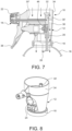
- the valve body 12 is further provided with a head portion 34 that is configured to receive a filling container (not shown) and has a flow-through filling passage 36 extending between the head portion 34 and the base portion 18 such that a liquid (see arrows Figs. 6-7 ) received in the head portion 34 flows through the valve body 12, around the pumping chamber 24 and exits the base portion 18 into the neck 20 of the mounted liquid container 16.
- the filling container may contain a pre-mixed liquid to be sprayed or contain a concentrate to be mixed with water in the container 16.
- the flow path 36 and liquid flow through the valve body 12 is best shown by the arrows in the cross-sectional views in Figs. 6 and 7 .
- the filling container may be snap fit or plug fit onto the head portion 34 of the valve body 12 or may include a bayonet type connection, or threaded connection or any other connection as known in the art.
- the filling container may be sealed and pierced as it is applied to the valve body 12, or may include a valve to release the contents.
- the valve body may include a separate flow valve (not shown) to selectively allow flow through the filling passage 36.
- assembly 10A includes a cover or shroud 48 with a hatch or door 50 that can be selectively opened and closed to allow the user to fill the container through the hatch or door 50.
- the cover can be part of a larger shroud, or can be a snap-fit or sealed cover with a sliding or hinged door. Other configurations are also contemplated.
- a trigger lever 38 is hinged to the valve body 12 and to a stem 40 of a plunger or piston 42 which is slidable in the pumping chamber 24 to suction and pump liquid from the liquid container 16.
- a spring 44 is captured between the trigger lever 38 and the valve body 12 to bias the trigger 38 outwardly.
- a suction and delivery valve 46 located within the pumping chamber 24 cooperates with the inlet duct 26 and the outlet duct 30 to control suction of the liquid from the container 16 and delivery of the liquid to the delivery nozzle 22. Operation of the pump assembly 14 and of the suction and delivery valve 46 are better described in US Patent Nos. 7,175,056 and 8,714,415 .
Landscapes
- Closures For Containers (AREA)
- Containers And Packaging Bodies Having A Special Means To Remove Contents (AREA)
Description
- (1) Field of the Invention: The instant invention relates to sprayer devices and more particularly to a liquid pump sprayer manually operated by means of a trigger lever.
- (2) Description of Related Art: Known sprayers are disclosed in
GB2310149 EP1134030 ,WO2004065021 ,US2010096414 ,andWO2014189994 . A sprayer of the type generally contemplated herein comprises a valve body provided with a base configured to be mounted to a neck of a liquid container, a delivery nozzle from which the liquid is sprayed, a spring biased trigger lever that is operated manually by the user and a pump operated by the trigger lever to suction liquid from the container and to spray it through the nozzle. The pump has a piston acting in a chamber formed in the valve body. The valve body further comprises an inlet duct with a connecting dip tube that extends from the pump chamber to the inside of the liquid container and an outlet duct extending from the pump chamber to the sprayer nozzle. Within the pump chamber there is a suction and delivery valve adapted to allow the liquid to be sucked in a one-way direction from the container up through the dip tube to the pump chamber and to deliver the liquid from the pump chamber to the delivery nozzle. While reference is made to sprayers for liquids, it should be understood that the presently described types of spray devices can also be used to spray any type of fluid, such as foams or the like. - While the existing pump sprayer are effective for their intended purposes, an ever-evolving consumer market requires novel and improved designs which provide for added functionality, a reduced number of parts and reduced connection and leak points.
- According to one aspect if the invention, there is provided a one piece, integrally molded valve body for use in a sprayer device, the valve body comprising: a base portion that is configured to be mounted to a neck of a liquid container; a pumping chamber; an inlet duct; an outlet duct having a vertical portion in fluid communication with said pumping chamber and a horizontal extension through which liquid from a container can exit the valve body; a head portion; and a flow-through filling passage extending between said head portion and said base portion, wherein a liquid received in said head portion flows through the valve body, around the pumping chamber, and exits the base portion and wherein said pumping chamber is, in use, in fluid communication with an inside of a fluid container through said inlet duct and wherein said pumping chamber can be, in use, in fluid communication with a delivery nozzle through an open end of said horizontal extension of said outlet duct.
- Optionally, said head portion is configured to receive a filling container.
- Optionally, the head portion comprises means for receiving and attaching a filling container, said means for receiving and attaching a filling container being arranged such that a filling container can be mounted onto the valve body such that a liquid received in the head portion can flow through the valve body, around the pumping chamber and exit the base portion.
- Optionally, said means for receiving and attaching a filling container comprises a snap-fit fitment, a plug-fit fitment; a bayonet type connection; or a threaded connection.
- Optionally, said filling passage extends around the sides and back of the pumping chamber.
- Optionally, the base portion of the valve body is snap fit onto the neck of the liquid container.
- According to another aspect of the invention for which protection is sought, there is provided a sprayer device comprising: the one piece, integrally molded valve body according to the above relevant paragraphs; a trigger lever hinged to the valve body and to a stem of a plunger in said pumping chamber; a spring captured between said trigger lever and said valve body; and a suction and delivery valve located within the pumping chamber to control suction of the liquid from the container and to control delivery of the liquid to an open end of the horizontal extension of the outlet duct.
- Optionally, said filling passage extends around the sides and back of the pumping chamber. Optionally, the base portion of the valve body is configured for snap fitting onto the neck of a liquid container. Optionally, the suction and delivery valve is elastomeric.
- Optionally, the head portion comprises means for receiving and attaching a filling container, said means for receiving and attaching a filling container being arranged such that a filling container can be mounted onto the head portion of the valve body such that a liquid received in the head portion can flow through the valve body, around the pumping chamber and exit the base portion into a liquid container when mounted on said base portion of the valve body. Optionally, the head portion is configured to receive a filling container by means of a snap-fit fitment; plug-fit fitment; bayonet type connection; or threaded connection.
- Optionally, a plug body is received into the top of the vertical portion of the outlet duct to force liquid into the horizontal extension of the outlet duct.
- According to yet another aspect of the invention, there is provided a spraying assembly comprising the sprayer device according to any of immediately preceding relevant paragraphs; a liquid container; and a filling container, the liquid container being mounted to the base portion of the valve body, and the filling container being mounted to the head portion of the valve body.
- It can thus be appreciated that the exemplary embodiment provides a unique valve body and sprayer which simplifies and reduces the number of parts while also reducing the number of potential leak points to the connections between the valve body base and the liquid container and the valve body head and the filling container.
- While the specification concludes with claims particularly pointing out and distinctly claiming particular embodiments of the instant invention, various embodiments of the invention can be more readily understood and appreciated from the following descriptions of various embodiments of the invention when read in conjunction with the accompanying drawings in which:
-
Fig. 1 is a perspective view of an exemplary embodiment of a trigger sprayer assembly having a pass through filling path; -
Fig. 2 is an exploded perspective view thereof; -
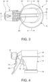
Fig. 3 is a top view thereof; -
Fig. 4 is a side view thereof; -
Fig. 5 is a bottom view thereof; -
Fig. 6 is a cross-sectional view thereof taken along line 6-6 ofFig. 3 ; -
Fig. 7 is another cross-sectional view thereof taken along line 7-7 ofFig. 3 ; -
Fig. 8 is a perspective view of the exemplary trigger sprayer valve body; -
Fig. 9 is a side view thereof; -
Fig. 10 is a top view thereof; -
Fig. 11 is a bottom view thereof; -
Fig. 12 is a cross-sectional view thereof taken along line 12-12 ofFig. 10 ; -
Fig 13 is another cross-sectional view thereof taken along line 13-13 ofFig. 10 ; -
Fig. 14 is a cross-sectional view of another exemplary trigger sprayer assembly with a cover and filling hatch. - Referring now to the drawings, an exemplary embodiment of a
trigger sprayer device 10 incorporating anexemplary valve body 12 is illustrated inFigs. 1-7 . Theexemplary valve body 12 is best illustrated inFigs. 8-13 . - The
exemplary sprayer device 10 comprises a trigger operated pump assembly 14 (SeeFig. 2 ) that is operative for pumping and spraying liquid from an attached liquid container 16 (SeeFig. 7 ). - The
sprayer device 10 includes an integrally moldedvalve body 12 provided with abase portion 18 that is configured to be mounted to a neck 20 of aliquid container 16. Theexemplary base portion 18 may be snap fit or plug fit onto the neck 20 of thecontainer 16 or may include a bayonet type connection, or threaded connection or any other connection as known in the art. - The
valve body 12 is provided with adelivery nozzle 22 from which liquid from thecontainer 16 is sprayed and has apumping chamber 24 which is in fluid communication with an inside of thefluid container 16 through aninlet duct 26 and a dip tube 28 (Fig. 7 ) which extends down into theliquid container 16 in a conventional manner. Thepumping chamber 24 is further in fluid communication with thedelivery nozzle 22 through anoutlet duct 30 having a vertical portion 30' and ahorizontal extension 30" leading to thedelivery nozzle 22. Aplug body 32 is received into the top of the vertical portion 30' of theoutlet duct 30 to force liquid into thehorizontal extension 30" of theoutlet duct 30. - The
valve body 12 is further provided with ahead portion 34 that is configured to receive a filling container (not shown) and has a flow-throughfilling passage 36 extending between thehead portion 34 and thebase portion 18 such that a liquid (see arrowsFigs. 6-7 ) received in thehead portion 34 flows through thevalve body 12, around thepumping chamber 24 and exits thebase portion 18 into the neck 20 of the mountedliquid container 16. The filling container may contain a pre-mixed liquid to be sprayed or contain a concentrate to be mixed with water in thecontainer 16. Theflow path 36 and liquid flow through thevalve body 12 is best shown by the arrows in the cross-sectional views inFigs. 6 and7 . The filling container may be snap fit or plug fit onto thehead portion 34 of thevalve body 12 or may include a bayonet type connection, or threaded connection or any other connection as known in the art. In one exemplary embodiment, the filling container may be sealed and pierced as it is applied to thevalve body 12, or may include a valve to release the contents. In another exemplary embodiment, the valve body may include a separate flow valve (not shown) to selectively allow flow through thefilling passage 36. - When the filling container is not present, the
open head portion 34 allows the user to fill theliquid container 16 with water or other spray liquid directly through the top of thevalve body 12 without removing thevalve body 12. In this regard, anotherexemplary embodiment 10A is shown inFig. 14 whereinassembly 10A includes a cover orshroud 48 with a hatch ordoor 50 that can be selectively opened and closed to allow the user to fill the container through the hatch ordoor 50. The cover can be part of a larger shroud, or can be a snap-fit or sealed cover with a sliding or hinged door. Other configurations are also contemplated. - A
trigger lever 38 is hinged to thevalve body 12 and to astem 40 of a plunger orpiston 42 which is slidable in thepumping chamber 24 to suction and pump liquid from theliquid container 16. Aspring 44 is captured between thetrigger lever 38 and thevalve body 12 to bias thetrigger 38 outwardly. A suction anddelivery valve 46 located within thepumping chamber 24 cooperates with theinlet duct 26 and theoutlet duct 30 to control suction of the liquid from thecontainer 16 and delivery of the liquid to thedelivery nozzle 22. Operation of thepump assembly 14 and of the suction anddelivery valve 46 are better described inUS Patent Nos. 7,175,056 and8,714,415 . - It can thus be appreciated that the exemplary embodiments provide a unique flow through or pass through
valve filling body 12 andsprayer 10 which simplifies and reduces the number of parts while also reducing the number of potential leak points to the connections between thevalve body base 18 and theliquid container 16, and thevalve body head 34 and the filling container. - While there is shown and described herein certain specific structures embodying various embodiments of the invention, it will be manifest to those skilled in the art that various modifications and rearrangements of the parts may be made without departing from the spirit and scope of the underlying inventive concept and that the same is not limited to the particular forms herein shown and described except insofar as indicated by the scope of the appended claims.
Claims (14)
- A one piece, integrally molded valve body (12) for use in a sprayer device, the valve body comprising: a base portion (18) that is configured to be mounted to a neck of a liquid container; a pumping chamber (24); an inlet duct (26); an outlet duct (30) having a vertical portion (30') in fluid communication with said pumping chamber (24) and a horizontal extension (30") through which liquid from a container can exit the valve body (12); a head portion (34); and a flow-through filling passage (36) extending between said head portion (34) and said base portion, wherein a liquid received in said head portion flows through the valve body, around the pumping chamber (24), and exits the base portion (18) and wherein said pumping chamber (24) is, in use, in fluid communication with an inside of a fluid container through said inlet duct and wherein said pumping chamber (24) can be, in use, in fluid communication with a delivery nozzle through an open end of said horizontal extension (30") of said outlet duct (30).
- The valve body of claim 1 wherein said head portion is configured to receive a filling container.
- The valve body of claim 1 or 2 wherein the head portion (34) comprises means for receiving and attaching a filling container, said means for receiving and attaching a filling container being arranged such that a filling container can be mounted onto the valve body such that a liquid received in the head portion (34) can flow through the valve body (12), around the pumping chamber (24) and exit the base portion (18).
- The valve body of claim 3 wherein said means for receiving and attaching a filling container comprises a snap-fit fitment, a plug-fit fitment; a bayonet type connection; or a threaded connection.
- The valve body of any claim 1 to 4 wherein said filling passage extends around the sides and back of the pumping chamber.
- The valve body of any claim 1 to 5 wherein the base portion of the valve body is snap fit onto the neck of the liquid container.
- A sprayer device (10) comprising:(i) the one piece, integrally molded valve body (12) according to claim 1;(ii) a trigger lever (38) hinged to the valve body (12) and to a stem of a plunger (42) in said pumping chamber (24);(iii) a spring (44) captured between said trigger lever (38) and said valve body (12); and(iv) a suction and delivery valve (46) located within the pumping chamber to control suction of the liquid from the container and to control delivery of the liquid to an open end of the horizontal extension (30") of the outlet duct (30).
- The sprayer device of claim 7 wherein said filling passage (36) extends around the sides and back of the pumping chamber (24).
- The sprayer device of claim 7 or 8 wherein the base portion (18) of the valve body (12) is configured for snap fitting onto the neck of a liquid container.
- The sprayer device of claim 7, 8 or 9 wherein the suction and delivery valve (46) is elastomeric.
- The sprayer device (10) of any preceding claim 7 to 10 wherein the head portion (34) comprises means for receiving and attaching a filling container, said means for receiving and attaching a filling container being arranged such that a filling container can be mounted onto the head portion (34) of the valve body (12) such that a liquid received in the head portion (34) can flow through the valve body (12), around the pumping chamber (24) and exit the base portion (18) into a liquid container (16) when mounted on said base portion (18) of the valve body (12).
- The sprayer device of claim 11 wherein the head portion (34) is configured to receive a filling container by means of a snap-fit fitment; plug-fit fitment; bayonet type connection; or threaded connection.
- The sprayer device (10) of any preceding claim 7 to 12 wherein a plug body (32) is received into the top of the vertical portion (30') of the outlet duct (30) to force liquid into the horizontal extension (30") of the outlet duct (30).
- A spraying assembly comprising the sprayer device (10) according to any of claims 7 to 13; a liquid container; and a filling container, the liquid container being mounted to the base portion (18) of the valve body (12), and the filling container being mounted to the head portion (34) of the valve body (12).
Applications Claiming Priority (1)
| Application Number | Priority Date | Filing Date | Title |
|---|---|---|---|
| US15/681,662 US10322428B2 (en) | 2017-08-21 | 2017-08-21 | Trigger spray valve body with pass through filling path |
Publications (2)
| Publication Number | Publication Date |
|---|---|
| EP3446790A1 EP3446790A1 (en) | 2019-02-27 |
| EP3446790B1 true EP3446790B1 (en) | 2025-05-28 |
Family
ID=63350449
Family Applications (1)
| Application Number | Title | Priority Date | Filing Date |
|---|---|---|---|
| EP18190036.6A Active EP3446790B1 (en) | 2017-08-21 | 2018-08-21 | Trigger sprayer valve body with pass through filling path |
Country Status (2)
| Country | Link |
|---|---|
| US (1) | US10322428B2 (en) |
| EP (1) | EP3446790B1 (en) |
Families Citing this family (4)
| Publication number | Priority date | Publication date | Assignee | Title |
|---|---|---|---|---|
| AU2019327412B2 (en) | 2018-08-27 | 2021-08-05 | S. C. Johnson & Son, Inc. | Trigger overcap assembly |
| USD880298S1 (en) * | 2018-08-27 | 2020-04-07 | S. C. Johnson & Son, Inc. | Actuator |
| CN112960268A (en) * | 2021-03-19 | 2021-06-15 | 浙江晟祺实业有限公司 | Full-plastic hand-fastening sprayer |
| CN218690641U (en) * | 2022-11-15 | 2023-03-24 | 宁波市康欣机电有限公司 | Spray gun convenient for liquid adding |
Family Cites Families (11)
| Publication number | Priority date | Publication date | Assignee | Title |
|---|---|---|---|---|
| US5385302A (en) * | 1990-10-25 | 1995-01-31 | Contico | Low cost trigger sprayer |
| US5570840A (en) * | 1994-10-14 | 1996-11-05 | Fourth And Long, Inc. | Hand-held spraying apparatus |
| GB2310149A (en) * | 1996-02-15 | 1997-08-20 | Nomix Chipman Ltd | Spray gun |
| DE29924728U1 (en) * | 1998-12-09 | 2005-04-14 | Schmid, Dieter | Spray container for plant watering has water container with dispensing head having fill opening for water |
| US6345738B1 (en) * | 2000-03-16 | 2002-02-12 | Owen-Illinois Closure Inc. | Pump dispenser having body with fill-through conduit |
| ITMI20030080A1 (en) * | 2003-01-21 | 2004-07-22 | Spray Plast Spa | SIMPLIFIED SPRAYER DEVICE. |
| US7766900B2 (en) * | 2005-02-21 | 2010-08-03 | Biomet Manufacturing Corp. | Method and apparatus for application of a fluid |
| IT1391100B1 (en) * | 2008-08-06 | 2011-11-18 | Spray Plast S P A Ora Mwv Vicenza S P A | SPRAYER FOR LIQUIDS |
| US20100096414A1 (en) * | 2008-10-20 | 2010-04-22 | Dennis Stephen R | Refillable Bottle Having Pour-Through Dispenser |
| US9409195B2 (en) * | 2011-04-13 | 2016-08-09 | Westrock Dispensing Systems, Inc. | Trigger sprayer valves |
| US9505015B2 (en) * | 2013-05-21 | 2016-11-29 | S. C. Johnson & Son, Inc. | Trigger sprayer with bottle filling conduit |
-
2017
- 2017-08-21 US US15/681,662 patent/US10322428B2/en active Active
-
2018
- 2018-08-21 EP EP18190036.6A patent/EP3446790B1/en active Active
Also Published As
| Publication number | Publication date |
|---|---|
| EP3446790A1 (en) | 2019-02-27 |
| US10322428B2 (en) | 2019-06-18 |
| US20190054487A1 (en) | 2019-02-21 |
Similar Documents
| Publication | Publication Date | Title |
|---|---|---|
| US11154889B2 (en) | Sprayer for liquids with precompression chamber | |
| US9010587B2 (en) | Trigger dispenser for liquids with a stop for the dispensing valve | |
| US7455198B2 (en) | Trigger forward pivot limit for a trigger sprayer | |
| US8714415B2 (en) | Sprayer for liquids | |
| EP1999060B1 (en) | Trigger sprayer with integral piston rod and u-shaped spring | |
| EP3446790A1 (en) | Trigger sprayer valve body with pass through filling path | |
| US8905270B2 (en) | Trigger dispenser for liquids with butt valves | |
| EP3043924B1 (en) | Sprayer | |
| CN100450637C (en) | Simplified nebulizer setup | |
| US8887967B2 (en) | Trigger dispenser for liquids with a suction valve | |
| CA2937575A1 (en) | Dispensing device | |
| US9908128B2 (en) | Sprayer for liquids with USD device that can be used also in horizontal position | |
| CN101595047A (en) | Metering device for dispensing doses of pressurized fluid | |
| CA2727074C (en) | Inverted dispenser pump with liquid inlet cup valve | |
| US11219910B2 (en) | Trigger sprayer with improved venting system and methods of using the same | |
| US20120273596A1 (en) | Low Cost Trigger Sprayer | |
| US20080223881A1 (en) | Trigger Sprayer Having a Two-Piece Shroud with Top and Bottom Pieces | |
| US20100019062A1 (en) | Tank sprayer with separate concentrate container | |
| US10994295B2 (en) | Spray device and methods for making the same | |
| US5722569A (en) | Trigger sprayer with discharge port blocking mechanism |
Legal Events
| Date | Code | Title | Description |
|---|---|---|---|
| PUAI | Public reference made under article 153(3) epc to a published international application that has entered the european phase |
Free format text: ORIGINAL CODE: 0009012 |
|
| STAA | Information on the status of an ep patent application or granted ep patent |
Free format text: STATUS: REQUEST FOR EXAMINATION WAS MADE |
|
| 17P | Request for examination filed |
Effective date: 20180821 |
|
| AK | Designated contracting states |
Kind code of ref document: A1 Designated state(s): AL AT BE BG CH CY CZ DE DK EE ES FI FR GB GR HR HU IE IS IT LI LT LU LV MC MK MT NL NO PL PT RO RS SE SI SK SM TR |
|
| AX | Request for extension of the european patent |
Extension state: BA ME |
|
| RIN1 | Information on inventor provided before grant (corrected) |
Inventor name: KRESTINE, JOSEPH Inventor name: ESPINOZA, ALEJANDRO Inventor name: VAN HOUTEN, BRIAN Inventor name: FLYNN, LEAH |
|
| STAA | Information on the status of an ep patent application or granted ep patent |
Free format text: STATUS: EXAMINATION IS IN PROGRESS |
|
| 17Q | First examination report despatched |
Effective date: 20200826 |
|
| GRAP | Despatch of communication of intention to grant a patent |
Free format text: ORIGINAL CODE: EPIDOSNIGR1 |
|
| STAA | Information on the status of an ep patent application or granted ep patent |
Free format text: STATUS: GRANT OF PATENT IS INTENDED |
|
| RIC1 | Information provided on ipc code assigned before grant |
Ipc: B05B 11/10 20230101ALI20241219BHEP Ipc: B05B 11/00 20060101AFI20241219BHEP |
|
| INTG | Intention to grant announced |
Effective date: 20250116 |
|
| GRAS | Grant fee paid |
Free format text: ORIGINAL CODE: EPIDOSNIGR3 |
|
| GRAA | (expected) grant |
Free format text: ORIGINAL CODE: 0009210 |
|
| STAA | Information on the status of an ep patent application or granted ep patent |
Free format text: STATUS: THE PATENT HAS BEEN GRANTED |
|
| AK | Designated contracting states |
Kind code of ref document: B1 Designated state(s): AL AT BE BG CH CY CZ DE DK EE ES FI FR GB GR HR HU IE IS IT LI LT LU LV MC MK MT NL NO PL PT RO RS SE SI SK SM TR |
|
| REG | Reference to a national code |
Ref country code: GB Ref legal event code: FG4D |
|
| REG | Reference to a national code |
Ref country code: CH Ref legal event code: EP |
|
| REG | Reference to a national code |
Ref country code: IE Ref legal event code: FG4D Ref country code: DE Ref legal event code: R096 Ref document number: 602018082252 Country of ref document: DE |
|
| P01 | Opt-out of the competence of the unified patent court (upc) registered |
Free format text: CASE NUMBER: APP_30121/2025 Effective date: 20250624 |
|
| REG | Reference to a national code |
Ref country code: NL Ref legal event code: MP Effective date: 20250528 |
|
| PG25 | Lapsed in a contracting state [announced via postgrant information from national office to epo] |
Ref country code: FI Free format text: LAPSE BECAUSE OF FAILURE TO SUBMIT A TRANSLATION OF THE DESCRIPTION OR TO PAY THE FEE WITHIN THE PRESCRIBED TIME-LIMIT Effective date: 20250528 Ref country code: ES Free format text: LAPSE BECAUSE OF FAILURE TO SUBMIT A TRANSLATION OF THE DESCRIPTION OR TO PAY THE FEE WITHIN THE PRESCRIBED TIME-LIMIT Effective date: 20250528 |
|
| PGFP | Annual fee paid to national office [announced via postgrant information from national office to epo] |
Ref country code: DE Payment date: 20250929 Year of fee payment: 8 |
|
| REG | Reference to a national code |
Ref country code: LT Ref legal event code: MG9D |
|
| PG25 | Lapsed in a contracting state [announced via postgrant information from national office to epo] |
Ref country code: NO Free format text: LAPSE BECAUSE OF FAILURE TO SUBMIT A TRANSLATION OF THE DESCRIPTION OR TO PAY THE FEE WITHIN THE PRESCRIBED TIME-LIMIT Effective date: 20250828 Ref country code: GR Free format text: LAPSE BECAUSE OF FAILURE TO SUBMIT A TRANSLATION OF THE DESCRIPTION OR TO PAY THE FEE WITHIN THE PRESCRIBED TIME-LIMIT Effective date: 20250829 |
|
| PG25 | Lapsed in a contracting state [announced via postgrant information from national office to epo] |
Ref country code: PL Free format text: LAPSE BECAUSE OF FAILURE TO SUBMIT A TRANSLATION OF THE DESCRIPTION OR TO PAY THE FEE WITHIN THE PRESCRIBED TIME-LIMIT Effective date: 20250528 Ref country code: NL Free format text: LAPSE BECAUSE OF FAILURE TO SUBMIT A TRANSLATION OF THE DESCRIPTION OR TO PAY THE FEE WITHIN THE PRESCRIBED TIME-LIMIT Effective date: 20250528 |
|
| PG25 | Lapsed in a contracting state [announced via postgrant information from national office to epo] |
Ref country code: BG Free format text: LAPSE BECAUSE OF FAILURE TO SUBMIT A TRANSLATION OF THE DESCRIPTION OR TO PAY THE FEE WITHIN THE PRESCRIBED TIME-LIMIT Effective date: 20250528 |
|
| PGFP | Annual fee paid to national office [announced via postgrant information from national office to epo] |
Ref country code: GB Payment date: 20250929 Year of fee payment: 8 |
|
| PG25 | Lapsed in a contracting state [announced via postgrant information from national office to epo] |
Ref country code: HR Free format text: LAPSE BECAUSE OF FAILURE TO SUBMIT A TRANSLATION OF THE DESCRIPTION OR TO PAY THE FEE WITHIN THE PRESCRIBED TIME-LIMIT Effective date: 20250528 |
|
| PGFP | Annual fee paid to national office [announced via postgrant information from national office to epo] |
Ref country code: FR Payment date: 20250925 Year of fee payment: 8 |
|
| PG25 | Lapsed in a contracting state [announced via postgrant information from national office to epo] |
Ref country code: RS Free format text: LAPSE BECAUSE OF FAILURE TO SUBMIT A TRANSLATION OF THE DESCRIPTION OR TO PAY THE FEE WITHIN THE PRESCRIBED TIME-LIMIT Effective date: 20250828 |
|
| PG25 | Lapsed in a contracting state [announced via postgrant information from national office to epo] |
Ref country code: IS Free format text: LAPSE BECAUSE OF FAILURE TO SUBMIT A TRANSLATION OF THE DESCRIPTION OR TO PAY THE FEE WITHIN THE PRESCRIBED TIME-LIMIT Effective date: 20250928 |
|
| PG25 | Lapsed in a contracting state [announced via postgrant information from national office to epo] |
Ref country code: LV Free format text: LAPSE BECAUSE OF FAILURE TO SUBMIT A TRANSLATION OF THE DESCRIPTION OR TO PAY THE FEE WITHIN THE PRESCRIBED TIME-LIMIT Effective date: 20250528 |
|
| REG | Reference to a national code |
Ref country code: AT Ref legal event code: MK05 Ref document number: 1798348 Country of ref document: AT Kind code of ref document: T Effective date: 20250528 |
|
| PG25 | Lapsed in a contracting state [announced via postgrant information from national office to epo] |
Ref country code: DK Free format text: LAPSE BECAUSE OF FAILURE TO SUBMIT A TRANSLATION OF THE DESCRIPTION OR TO PAY THE FEE WITHIN THE PRESCRIBED TIME-LIMIT Effective date: 20250528 Ref country code: AT Free format text: LAPSE BECAUSE OF FAILURE TO SUBMIT A TRANSLATION OF THE DESCRIPTION OR TO PAY THE FEE WITHIN THE PRESCRIBED TIME-LIMIT Effective date: 20250528 Ref country code: SM Free format text: LAPSE BECAUSE OF FAILURE TO SUBMIT A TRANSLATION OF THE DESCRIPTION OR TO PAY THE FEE WITHIN THE PRESCRIBED TIME-LIMIT Effective date: 20250528 |
|
| PG25 | Lapsed in a contracting state [announced via postgrant information from national office to epo] |
Ref country code: CZ Free format text: LAPSE BECAUSE OF FAILURE TO SUBMIT A TRANSLATION OF THE DESCRIPTION OR TO PAY THE FEE WITHIN THE PRESCRIBED TIME-LIMIT Effective date: 20250528 |
|
| PG25 | Lapsed in a contracting state [announced via postgrant information from national office to epo] |
Ref country code: EE Free format text: LAPSE BECAUSE OF FAILURE TO SUBMIT A TRANSLATION OF THE DESCRIPTION OR TO PAY THE FEE WITHIN THE PRESCRIBED TIME-LIMIT Effective date: 20250528 |
|
| PG25 | Lapsed in a contracting state [announced via postgrant information from national office to epo] |
Ref country code: SK Free format text: LAPSE BECAUSE OF FAILURE TO SUBMIT A TRANSLATION OF THE DESCRIPTION OR TO PAY THE FEE WITHIN THE PRESCRIBED TIME-LIMIT Effective date: 20250528 Ref country code: RO Free format text: LAPSE BECAUSE OF FAILURE TO SUBMIT A TRANSLATION OF THE DESCRIPTION OR TO PAY THE FEE WITHIN THE PRESCRIBED TIME-LIMIT Effective date: 20250528 |
|
| PG25 | Lapsed in a contracting state [announced via postgrant information from national office to epo] |
Ref country code: IT Free format text: LAPSE BECAUSE OF FAILURE TO SUBMIT A TRANSLATION OF THE DESCRIPTION OR TO PAY THE FEE WITHIN THE PRESCRIBED TIME-LIMIT Effective date: 20250528 |
|
| REG | Reference to a national code |
Ref country code: DE Ref legal event code: R097 Ref document number: 602018082252 Country of ref document: DE |
|
| REG | Reference to a national code |
Ref country code: CH Ref legal event code: H13 Free format text: ST27 STATUS EVENT CODE: U-0-0-H10-H13 (AS PROVIDED BY THE NATIONAL OFFICE) Effective date: 20260324 |
|
| PG25 | Lapsed in a contracting state [announced via postgrant information from national office to epo] |
Ref country code: MC Free format text: LAPSE BECAUSE OF FAILURE TO SUBMIT A TRANSLATION OF THE DESCRIPTION OR TO PAY THE FEE WITHIN THE PRESCRIBED TIME-LIMIT Effective date: 20250528 |
|
| PLBE | No opposition filed within time limit |
Free format text: ORIGINAL CODE: 0009261 |
|
| STAA | Information on the status of an ep patent application or granted ep patent |
Free format text: STATUS: NO OPPOSITION FILED WITHIN TIME LIMIT |
|
| REG | Reference to a national code |
Ref country code: CH Ref legal event code: L10 Free format text: ST27 STATUS EVENT CODE: U-0-0-L10-L00 (AS PROVIDED BY THE NATIONAL OFFICE) Effective date: 20260409 |
|
| PG25 | Lapsed in a contracting state [announced via postgrant information from national office to epo] |
Ref country code: LU Free format text: LAPSE BECAUSE OF NON-PAYMENT OF DUE FEES Effective date: 20250821 |
|
| PG25 | Lapsed in a contracting state [announced via postgrant information from national office to epo] |
Ref country code: CH Free format text: LAPSE BECAUSE OF NON-PAYMENT OF DUE FEES Effective date: 20250831 |
|
| REG | Reference to a national code |
Ref country code: BE Ref legal event code: MM Effective date: 20250831 |
|
| 26N | No opposition filed |
Effective date: 20260303 |
|
| PG25 | Lapsed in a contracting state [announced via postgrant information from national office to epo] |
Ref country code: LT Free format text: LAPSE BECAUSE OF FAILURE TO SUBMIT A TRANSLATION OF THE DESCRIPTION OR TO PAY THE FEE WITHIN THE PRESCRIBED TIME-LIMIT Effective date: 20250528 |
|
| PG25 | Lapsed in a contracting state [announced via postgrant information from national office to epo] |
Ref country code: PT Free format text: LAPSE BECAUSE OF NON-PAYMENT OF DUE FEES Effective date: 20250528 |
|
| PG25 | Lapsed in a contracting state [announced via postgrant information from national office to epo] |
Ref country code: BE Free format text: LAPSE BECAUSE OF NON-PAYMENT OF DUE FEES Effective date: 20250831 Ref country code: IE Free format text: LAPSE BECAUSE OF NON-PAYMENT OF DUE FEES Effective date: 20250821 |
|
| PG25 | Lapsed in a contracting state [announced via postgrant information from national office to epo] |
Ref country code: SE Free format text: LAPSE BECAUSE OF FAILURE TO SUBMIT A TRANSLATION OF THE DESCRIPTION OR TO PAY THE FEE WITHIN THE PRESCRIBED TIME-LIMIT Effective date: 20250528 |