EP3446766A1 - Compressor system separator tank baffle - Google Patents
Compressor system separator tank baffle Download PDFInfo
- Publication number
- EP3446766A1 EP3446766A1 EP18190858.3A EP18190858A EP3446766A1 EP 3446766 A1 EP3446766 A1 EP 3446766A1 EP 18190858 A EP18190858 A EP 18190858A EP 3446766 A1 EP3446766 A1 EP 3446766A1
- Authority
- EP
- European Patent Office
- Prior art keywords
- baffle
- louvers
- separator tank
- openings
- compressed gas
- Prior art date
- Legal status (The legal status is an assumption and is not a legal conclusion. Google has not performed a legal analysis and makes no representation as to the accuracy of the status listed.)
- Granted
Links
Images




Classifications
-
- B—PERFORMING OPERATIONS; TRANSPORTING
- B01—PHYSICAL OR CHEMICAL PROCESSES OR APPARATUS IN GENERAL
- B01D—SEPARATION
- B01D45/00—Separating dispersed particles from gases or vapours by gravity, inertia, or centrifugal forces
- B01D45/04—Separating dispersed particles from gases or vapours by gravity, inertia, or centrifugal forces by utilising inertia
- B01D45/06—Separating dispersed particles from gases or vapours by gravity, inertia, or centrifugal forces by utilising inertia by reversal of direction of flow
-
- F—MECHANICAL ENGINEERING; LIGHTING; HEATING; WEAPONS; BLASTING
- F04—POSITIVE - DISPLACEMENT MACHINES FOR LIQUIDS; PUMPS FOR LIQUIDS OR ELASTIC FLUIDS
- F04C—ROTARY-PISTON, OR OSCILLATING-PISTON, POSITIVE-DISPLACEMENT MACHINES FOR LIQUIDS; ROTARY-PISTON, OR OSCILLATING-PISTON, POSITIVE-DISPLACEMENT PUMPS
- F04C29/00—Component parts, details or accessories of pumps or pumping installations, not provided for in groups F04C18/00 - F04C28/00
- F04C29/02—Lubrication; Lubricant separation
- F04C29/026—Lubricant separation
-
- B—PERFORMING OPERATIONS; TRANSPORTING
- B01—PHYSICAL OR CHEMICAL PROCESSES OR APPARATUS IN GENERAL
- B01D—SEPARATION
- B01D45/00—Separating dispersed particles from gases or vapours by gravity, inertia, or centrifugal forces
- B01D45/04—Separating dispersed particles from gases or vapours by gravity, inertia, or centrifugal forces by utilising inertia
- B01D45/08—Separating dispersed particles from gases or vapours by gravity, inertia, or centrifugal forces by utilising inertia by impingement against baffle separators
-
- F—MECHANICAL ENGINEERING; LIGHTING; HEATING; WEAPONS; BLASTING
- F04—POSITIVE - DISPLACEMENT MACHINES FOR LIQUIDS; PUMPS FOR LIQUIDS OR ELASTIC FLUIDS
- F04B—POSITIVE-DISPLACEMENT MACHINES FOR LIQUIDS; PUMPS
- F04B39/00—Component parts, details, or accessories, of pumps or pumping systems specially adapted for elastic fluids, not otherwise provided for in, or of interest apart from, groups F04B25/00 - F04B37/00
-
- F—MECHANICAL ENGINEERING; LIGHTING; HEATING; WEAPONS; BLASTING
- F04—POSITIVE - DISPLACEMENT MACHINES FOR LIQUIDS; PUMPS FOR LIQUIDS OR ELASTIC FLUIDS
- F04B—POSITIVE-DISPLACEMENT MACHINES FOR LIQUIDS; PUMPS
- F04B39/00—Component parts, details, or accessories, of pumps or pumping systems specially adapted for elastic fluids, not otherwise provided for in, or of interest apart from, groups F04B25/00 - F04B37/00
- F04B39/02—Lubrication
-
- B—PERFORMING OPERATIONS; TRANSPORTING
- B01—PHYSICAL OR CHEMICAL PROCESSES OR APPARATUS IN GENERAL
- B01D—SEPARATION
- B01D17/00—Separation of liquids, not provided for elsewhere, e.g. by thermal diffusion
- B01D17/02—Separation of non-miscible liquids
- B01D17/0208—Separation of non-miscible liquids by sedimentation
-
- B—PERFORMING OPERATIONS; TRANSPORTING
- B01—PHYSICAL OR CHEMICAL PROCESSES OR APPARATUS IN GENERAL
- B01D—SEPARATION
- B01D17/00—Separation of liquids, not provided for elsewhere, e.g. by thermal diffusion
- B01D17/02—Separation of non-miscible liquids
- B01D17/0208—Separation of non-miscible liquids by sedimentation
- B01D17/0211—Separation of non-miscible liquids by sedimentation with baffles
-
- B—PERFORMING OPERATIONS; TRANSPORTING
- B01—PHYSICAL OR CHEMICAL PROCESSES OR APPARATUS IN GENERAL
- B01D—SEPARATION
- B01D21/00—Separation of suspended solid particles from liquids by sedimentation
- B01D21/0039—Settling tanks provided with contact surfaces, e.g. baffles, particles
- B01D21/0042—Baffles or guide plates
-
- B—PERFORMING OPERATIONS; TRANSPORTING
- B01—PHYSICAL OR CHEMICAL PROCESSES OR APPARATUS IN GENERAL
- B01D—SEPARATION
- B01D21/00—Separation of suspended solid particles from liquids by sedimentation
- B01D21/0039—Settling tanks provided with contact surfaces, e.g. baffles, particles
- B01D21/0045—Plurality of essentially parallel plates
-
- F—MECHANICAL ENGINEERING; LIGHTING; HEATING; WEAPONS; BLASTING
- F04—POSITIVE - DISPLACEMENT MACHINES FOR LIQUIDS; PUMPS FOR LIQUIDS OR ELASTIC FLUIDS
- F04C—ROTARY-PISTON, OR OSCILLATING-PISTON, POSITIVE-DISPLACEMENT MACHINES FOR LIQUIDS; ROTARY-PISTON, OR OSCILLATING-PISTON, POSITIVE-DISPLACEMENT PUMPS
- F04C18/00—Rotary-piston pumps specially adapted for elastic fluids
- F04C18/08—Rotary-piston pumps specially adapted for elastic fluids of intermeshing-engagement type, i.e. with engagement of co-operating members similar to that of toothed gearing
- F04C18/12—Rotary-piston pumps specially adapted for elastic fluids of intermeshing-engagement type, i.e. with engagement of co-operating members similar to that of toothed gearing of other than internal-axis type
- F04C18/14—Rotary-piston pumps specially adapted for elastic fluids of intermeshing-engagement type, i.e. with engagement of co-operating members similar to that of toothed gearing of other than internal-axis type with toothed rotary pistons
- F04C18/16—Rotary-piston pumps specially adapted for elastic fluids of intermeshing-engagement type, i.e. with engagement of co-operating members similar to that of toothed gearing of other than internal-axis type with toothed rotary pistons with helical teeth, e.g. chevron-shaped, screw type
-
- Y—GENERAL TAGGING OF NEW TECHNOLOGICAL DEVELOPMENTS; GENERAL TAGGING OF CROSS-SECTIONAL TECHNOLOGIES SPANNING OVER SEVERAL SECTIONS OF THE IPC; TECHNICAL SUBJECTS COVERED BY FORMER USPC CROSS-REFERENCE ART COLLECTIONS [XRACs] AND DIGESTS
- Y10—TECHNICAL SUBJECTS COVERED BY FORMER USPC
- Y10S—TECHNICAL SUBJECTS COVERED BY FORMER USPC CROSS-REFERENCE ART COLLECTIONS [XRACs] AND DIGESTS
- Y10S418/00—Rotary expansible chamber devices
- Y10S418/01—Non-working fluid separation
Definitions
- the present invention generally relates to compressor system separator tanks, and more particularly, but not exclusively, to compressor system separator tanks having internal baffling.
- One embodiment of the present invention is a unique baffle for use with a compressor system separator tank.
- Other embodiments include apparatuses, systems, devices, hardware, methods, and combinations for separating coolant/lubricant from a flow of compressed gas. Further embodiments, forms, features, aspects, benefits, and advantages of the present application shall become apparent from the description and figures provided herewith.
- a compressor system 50 which includes a compressor 52 used to pressurize an incoming gas 54 as well as a separator tank 56 useful to separate a flow 58 that includes compressed gas and a byproduct of compression such as a lubricant and or coolant (e.g. a lubricant or coolant mist).
- a lubricant and or coolant e.g. a lubricant or coolant mist
- a lubricant and or coolant e.g. a lubricant or coolant mist.
- the compressor 52 can take on any variety of forms, and in one nonlimiting embodiment is a contact cooled compressor useful to compress a flow of air.
- the separator tank can pass along a filtered flow of compressed gas 60 and the byproduct of compression 62 (e.g. lubricant such as oil).
- the compressor system 50 is shown with just a compressor 52 and separator 56, other embodiments can include further devices, such as dryers, etc.
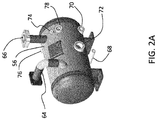
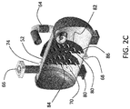
- FIGS. 2A-2C various views of a separator tank 56 are shown.
- FIG. 2A depicts a perspective view of the outside of the separator tank 56;
- FIG. 2B depicts a view in which the outside of the separator tank is faded to reveal the interior of the tank 56;
- FIG. 2C depicts a cutaway view of the tank 56.
- the tank 56 can be cylindrical in some forms, but not all embodiments.
- the tank 56 can have a circular outer periphery and/or inner periphery, but other cross sectional shapes are also contemplated.
- the tank 56 includes an inlet passage 64 for receipt of the mixed flow 58 of compressed gas and lubricant passed from the compressor 52, as well as an outlet passage 66 for conveyance of compressed air in which at least some of the lubricant (e.g. lubricant mist) is removed.
- the inlet passage 64 can be arranged to deliver the mixed flow 58 to an inside face of an end of the tank 56, as can be seen in FIGS. 2B and 2C .
- the outlet passage can be used in some forms to pass pre-separated air with oil traces to an air-oil-separator element prior to being delivered elsewhere. As will be appreciated, although an air-oil-separator element can be used, it need not be used in all applications.
- the separator tank 56 can also include a drain port 68 and an oil port 70 used to convey oil to a thermal control valve (e.g. a valve that will regulate whether oil is passaged to an oil cooler before being recycled for later use in the compressor 52).
- a thermal control valve e.g. a valve that will regulate whether oil is passaged to an oil cooler before being recycled for later use in the compressor 52.
- the separator tank 56 can also include other features such as a sight glass 72, pressure measurement port 74, safety valve 76, and an oil fill port 78.
- a baffle 80 is used internal to the tank 56 to further aid in the removal of lubricant mist from the flow.
- the baffle 80 is sized to extend substantially across the entirety of the inside of the tank 56 and includes a number of passages 82 and louvers 84.
- the passages 82 and louvers 84 are arranged in a grid like pattern with a middle three rows and three columns bounded on top and bottom by a set of two which is also bounded by a single passage 82 and louver 84 combination.
- Other variations are also contemplated.
- any number of passages can be used in any combination and/or arrangement.
- each passage 82 includes a paired louver 84, not all embodiments need include louvers 84 for each passage 82.
- the passages 82 can have any variety of cross sections, sizes, and numbers. In some forms the passages 82 need not be identical, although the passages are depicted as the same in the illustrated embodiment.
- the illustrated embodiment depicts passages 82 having a cross sectional shape of a rectangle in the illustrated embodiment.
- the material of the baffle 80 located between and around the passages 82 can provide a blockage that varies from embodiment to embodiment.
- the cross sectional area of the passages 82 can represent about the same cross sectional as the material located between and around the passages 82 and that define the shape of the baffle 80.
- the cross sectional area of the passages 82 can represent differing amounts, either higher or lower than the cross sectional area of the material defining the baffle. As shown in the illustrated embodiment, the cross sectional area of the passages is less than that of the cross sectional area of the material defining the baffle.
- the louvers 84 extend from the baffle 80 and are generally associated with each individual passage 82, although not all passages 82 need include a louver 84.
- the louvers 84 can take on a variety of shapes and sizes and are usually all located on the same side of the baffle 80 (not all embodiments need include louvers 84 on the same side).
- the louvers 84 depicted in the illustrated embodiment are rectilinear and can have the same or roughly same shape and size as the passages 82.
- the louvers 84 can extend from the baffle 80 any dimension and at any orientation sufficient to achieve a separation function but large enough to permit passage of compressed air without inordinate blockage and/or choking of the flow.
- the louvers 84 extend from the passages 82 at about a 30 degree angle measured, but other angles are also contemplated, such as but not limited to 20, 40, 45, 50, and 60 degrees.
- the louvers 84 are located at the top of the passages 82, but other locations can also be used.
- the louvers 84 can be rigidly attached to the baffle 80.
- the louvers 84 are integral to the baffle 80.
- the louvers 84 can be formed via a stamping operation useful to form the passages 82 and bend the louvers 84 to an appropriate orientation. Such a stamping operation results in a locally yielded material between the main part of the louvers 84 and the baffle 80. Other techniques of formation are also contemplated.
- a mixed flow 58 of compressed gas and lubricant can be received in and delivered against one end of the tank 56.
- the flow progressed from the inlet 64 to the outlet 66 by first traversing through the baffles 80.
- the flow enters the passages 82 and traverses from an upstream side to a downstream side in which the flow encounters the louvers 84.
- the louvers 84 Upon encountering the louvers 84 on the downstream side the flow is directed downward which interaction aids in further separation of compressed gas from the lubricant.
- the separation of the compressed gas and lubricant can be enabled by a change in direction and/or deceleration without any additional energy added to the system.
- the baffle 80 can include a relief 86 formed in a bottom of the baffle 80 to assist in providing liquid levelling within the tank 56.
- the relief is represented by a cutout edge of the baffle 80 such that the baffle 80 when installed will substantially contact the interior of the tank around a majority of its circumference with the exception of a small offset at the bottom of the baffle 80 between the relief 86 and the tank 56.
- baffles 80 are shown as identical, in some forms the baffles 80 can be different depending on the application.
- one of the baffles 80 can include additional or differently formed passages 82 and/or louvers 84.
- the baffles 80 can sit vertical in the tank, but other angles are also contemplated. In those embodiments having two or more baffles 80, each of the separate baffles 80 can sit at the same, or at different angles.
- baffles 80 in some embodiments only a single baffle may be used, and can be located anywhere in the tank 56.
- a single baffle 80 may be used and located closest to the inlet side of the tank 56, while in other embodiments a single baffle 80 may be used and located closer to the outlet of the tank 56.
- any number of baffles 80 can be used.
- the baffle 80 can be formed using a variety of approaches.
- a material sheet stock can be provided from which can be cut the general outline of the baffle 80.
- the cutting action can use any variety of techniques such as laser cutting, die cutting, etc.
- the cut sheet stock can be processed further by a stamping action to form the passages 82 and louvers 84.
- the relief 86 can be formed from the original cutting action or the stamping procedure. Alternatively and/or additionally, the cutting and stamping action can be done in a single process step. Other processes are also contemplated.
- the baffle 80 can be formed via additive manufacturing, casting, etc.
- the baffle 80 and/or tank 56 can be made from any variety of materials, including non-metallic materials.
- the baffle 80 and/or tank 56 can be made from plastic, ceramic, etc. After formation the baffle 80 can be installed in the tank 56 using any variety of approaches such as mechanical (e.g. fasteners), metallurgical (e.g. welding), and chemical (e.g. bonding) to set forth just a few nonlimiting examples.
- mechanical e.g. fasteners
- metallurgical e.g. welding
- chemical e.g. bonding
- one embodiment of the separator tank 56 includes a baffle 80 which is captured in place via flanges 88.
- the flanges 88 are depicted as bolted together in the illustrated embodiment, but can be fastened using other techniques as well.
- the embodiment depicted in FIGS. 3A-3B illustrate a separator tank 56 having two baffles 80 that are each captured in place via flanges 88, but other embodiments can include a mix of flange-capture and welded baffles 80.
- the separator tank may only include baffles 80 which are welded in place inside of the tank without use of any flanges.
- the baffles 80 can be formed integral with the tank 56.
- the baffles 80 and tank 56 can be formed through a casting process or through additive manufacturing, among any others that permit integral formation of the two.
- one or more baffles 80 can be used in any given embodiment of the separator tank.
- One aspect of the present application includes an apparatus comprising a compressor system separation tank having an inlet structured to receive a flow mixture of oil and compressed gas and an outlet to pass compressed gas, the separation tank including a baffle disposed located intermediate a first end and a second end of the separation tank, the baffle including a plurality of passages that permit a flow of compressed gas to pass from an upstream side of the baffle to a downstream side of the baffle, the baffle including a plurality of louvers that each extend from the plurality of passages in the baffle.
- a feature of the present application includes wherein the plurality of louvers are oriented to point in a direction toward an end of the baffle.
- Another feature of the present application includes wherein the plurality of louvers each span the width of its associated passage of the plurality of passages.
- Still another feature of the present application includes wherein the plurality of louvers are each flat, and wherein the compressor system separation tank is a horizontal separation tank, wherein the baffle sits vertically within the separation tank, and wherein the louvers are on the downstream side of the baffle.
- Yet another feature of the present application includes wherein the cross sectional area of the plurality of passages is less than the cross sectional area of the baffle material that surrounds the plurality of passages.
- Still yet another feature of the present application includes wherein the plurality of louvers are pointed in the direction of flow such that an overhanging side of the louvers is on the downstream side of the baffle.
- Yet still another feature of the present application further includes a second baffle, the second baffle including a plurality of openings and a plurality of louvers extending from the opening, and wherein the baffle and the second baffle each include a relief formed in an edge such that a passage is formed between an inside surface of the compressor system separation tank and the edge of the baffle.
- Another aspect of the present application includes an apparatus comprising a compressor separation tank structured to remove lubricant from a flow of compressed gas, an inlet structured to receive a flow of the compressed gas and lubricant, an outlet structured to pass the compressed gas after removal of at least part of the lubricant that is received by the inlet, and a baffle disposed intermediate the inlet and the outlet, the baffle having a plurality of separate openings structured to communicate compressed gas from one side of the baffle to the other, each of the plurality of separate openings positioned adjacent a corresponding overhanging louver that extends away from the baffle.
- a feature of the present application includes wherein the overhanging louver is positioned at the top of the each of the plurality of separate openings.
- the compressor separation tank is a horizontal separation tank in which the baffle is positioned upright on its end and fluid flows horizontally from one side of the baffle to the other side.
- Still another feature of the present application includes wherein the baffle includes a relief formed in a bottom of the baffle such that an opening is provided to permit lubricant to flow freely from one side of the baffle to the other.
- Yet another feature of the present application includes wherein the relief formed in the baffle is a flat bottom such that the passage is formed as a half-moon shape, the half-moon shape of the passage including a rounded bottom and a flat top.
- Still yet another feature of the present application includes wherein the plurality of louvers are formed by stamping action such that a plurality of corners are formed between the baffle and the plurality of louvers wherein the corners are characterized by a locally yielded material, and wherein as a result of the stamping action each of the plurality of louvers are thus sized to fit within associated passages of the plurality of passages.
- Yet still another feature of the present application further includes a second baffle positioned within the compressor separation tank.
- Yet another aspect of the present application includes a method comprising providing a main cylindrical body of a horizontal separation tank structured to contain a pressurized flow of compressed gas and lubricant, inserting a baffle into the interior of the main cylindrical body of the horizontal separation tank, the baffle including a plurality of through openings structured to pass compressed gas, the plurality of through openings each including an associated louver that extends from the baffle, and fixing the baffle into place within the interior of the main cylindrical body.
- a feature of the present application includes wherein the fixing includes welding the baffle in place within the main cylindrical body of the horizontal separation tank.
- Another feature of the present application includes wherein the inserting includes forming a passage space between the bottom of the main cylindrical body and a relief formed at the bottom of the baffle.
- Yet another feature of the present application further includes fastening end caps to the open ends of the main cylindrical body of the horizontal separation tank.
- Still another feature of the present application further includes forming the baffle by cutting a piece of material sheet stock.
- Yet still another feature of the present application includes wherein the cutting includes at least one of die cutting and laser cutting.
- Still yet another feature of the present application includes wherein the forming further includes stamping the piece of material sheet stock.
- the present application provides a method comprising providing a main body of a horizontal separation tank structured to contain a pressurized flow of compressed gas and lubricant, inserting a baffle into the interior of the main body of the horizontal separation tank, the baffle including a plurality of through openings structured to pass compressed gas, the plurality of through openings each including an associated louver that extends from the baffle, and fixing the baffle into place within the interior of the main body.
- One feature of the present application includes wherein the fixing includes welding the baffle in place within the main body of the horizontal separation tank.
- Another feature of the present application includes wherein the inserting includes forming a passage space between the bottom of the main body and a relief formed at the bottom of the baffle.
- Yet another feature of the present application further includes fastening end caps to the open ends of the main body of the horizontal separation tank.
- Still another feature of the present application further includes forming the baffle by cutting a piece of material sheet stock.
- Still yet another feature of the present application includes wherein the cutting includes at least one of die cutting and laser cutting.
- Yet still another feature of the present application includes wherein the forming further includes stamping the piece of material sheet stock.
Landscapes
- Engineering & Computer Science (AREA)
- Chemical & Material Sciences (AREA)
- Chemical Kinetics & Catalysis (AREA)
- Mechanical Engineering (AREA)
- General Engineering & Computer Science (AREA)
- Compressor (AREA)
- Separating Particles In Gases By Inertia (AREA)
Abstract
Description
- The present invention generally relates to compressor system separator tanks, and more particularly, but not exclusively, to compressor system separator tanks having internal baffling.
- Providing baffling to aid in the separation of compressed gas from liquids such as coolants/lubricants remains an area of interest. Some existing systems have various shortcomings relative to certain applications. Accordingly, there remains a need for further contributions in this area of technology.
- One embodiment of the present invention is a unique baffle for use with a compressor system separator tank. Other embodiments include apparatuses, systems, devices, hardware, methods, and combinations for separating coolant/lubricant from a flow of compressed gas. Further embodiments, forms, features, aspects, benefits, and advantages of the present application shall become apparent from the description and figures provided herewith.
-
-
FIG. 1 depicts one embodiment of a compressor system. -
FIG. 2A depicts a view of one embodiment of a separator tank. -
FIG. 2B depicts another view of the embodiment of the separator tank shown inFIG. 2A . -
FIG. 2C depicts another view of the embodiment of the separator tank shown inFIG. 2A . -
FIG. 3A depicts a view of another embodiment of a separator tank. -
FIG. 3B depicts another view of the embodiment of the separator tank shown inFIG. 3A . - For the purposes of promoting an understanding of the principles of the invention, reference will now be made to the embodiments illustrated in the drawings and specific language will be used to describe the same. It will nevertheless be understood that no limitation of the scope of the invention is thereby intended. Any alterations and further modifications in the described embodiments, and any further applications of the principles of the invention as described herein are contemplated as would normally occur to one skilled in the art to which the invention relates.
- With reference to
FIG. 1 , acompressor system 50 is illustrated which includes acompressor 52 used to pressurize anincoming gas 54 as well as aseparator tank 56 useful to separate aflow 58 that includes compressed gas and a byproduct of compression such as a lubricant and or coolant (e.g. a lubricant or coolant mist). Further discussion below may refer to the byproduct of compression as the lubricant and/or the coolant, but no limitation is hereby intended regarding the use of the byproduct whether solely as a lubricant or solely as a coolant. Mention of either lubricant or coolant refers generally to the byproduct and not the intended use of the byproduct. Thus, any mention of lubricant can apply equally to the byproduct used primarily as a coolant, and vice versa. - The
compressor 52 can take on any variety of forms, and in one nonlimiting embodiment is a contact cooled compressor useful to compress a flow of air. The separator tank can pass along a filtered flow of compressedgas 60 and the byproduct of compression 62 (e.g. lubricant such as oil). Though thecompressor system 50 is shown with just acompressor 52 andseparator 56, other embodiments can include further devices, such as dryers, etc. - Turning now to
FIGS. 2A-2C , various views of aseparator tank 56 are shown.FIG. 2A depicts a perspective view of the outside of theseparator tank 56;FIG. 2B depicts a view in which the outside of the separator tank is faded to reveal the interior of thetank 56; andFIG. 2C depicts a cutaway view of thetank 56. Thetank 56 can be cylindrical in some forms, but not all embodiments. For example, thetank 56 can have a circular outer periphery and/or inner periphery, but other cross sectional shapes are also contemplated. Thetank 56 includes aninlet passage 64 for receipt of the mixedflow 58 of compressed gas and lubricant passed from thecompressor 52, as well as anoutlet passage 66 for conveyance of compressed air in which at least some of the lubricant (e.g. lubricant mist) is removed. Theinlet passage 64 can be arranged to deliver the mixedflow 58 to an inside face of an end of thetank 56, as can be seen inFIGS. 2B and2C . The outlet passage can be used in some forms to pass pre-separated air with oil traces to an air-oil-separator element prior to being delivered elsewhere. As will be appreciated, although an air-oil-separator element can be used, it need not be used in all applications. Theseparator tank 56 can also include adrain port 68 and anoil port 70 used to convey oil to a thermal control valve (e.g. a valve that will regulate whether oil is passaged to an oil cooler before being recycled for later use in the compressor 52). Theseparator tank 56 can also include other features such as asight glass 72,pressure measurement port 74,safety valve 76, and anoil fill port 78. - A
baffle 80 is used internal to thetank 56 to further aid in the removal of lubricant mist from the flow. Thebaffle 80 is sized to extend substantially across the entirety of the inside of thetank 56 and includes a number ofpassages 82 andlouvers 84. Thepassages 82 andlouvers 84 are arranged in a grid like pattern with a middle three rows and three columns bounded on top and bottom by a set of two which is also bounded by asingle passage 82 andlouver 84 combination. Other variations are also contemplated. For example, any number of passages can be used in any combination and/or arrangement. Although eachpassage 82 includes a pairedlouver 84, not all embodiments need includelouvers 84 for eachpassage 82. - The
passages 82 can have any variety of cross sections, sizes, and numbers. In some forms thepassages 82 need not be identical, although the passages are depicted as the same in the illustrated embodiment. The illustrated embodiment depictspassages 82 having a cross sectional shape of a rectangle in the illustrated embodiment. The material of thebaffle 80 located between and around thepassages 82 can provide a blockage that varies from embodiment to embodiment. In some forms the cross sectional area of thepassages 82 can represent about the same cross sectional as the material located between and around thepassages 82 and that define the shape of thebaffle 80. In other forms the cross sectional area of thepassages 82 can represent differing amounts, either higher or lower than the cross sectional area of the material defining the baffle. As shown in the illustrated embodiment, the cross sectional area of the passages is less than that of the cross sectional area of the material defining the baffle. - The
louvers 84 extend from thebaffle 80 and are generally associated with eachindividual passage 82, although not allpassages 82 need include alouver 84. Thelouvers 84 can take on a variety of shapes and sizes and are usually all located on the same side of the baffle 80 (not all embodiments need includelouvers 84 on the same side). Thelouvers 84 depicted in the illustrated embodiment are rectilinear and can have the same or roughly same shape and size as thepassages 82. - The
louvers 84 can extend from thebaffle 80 any dimension and at any orientation sufficient to achieve a separation function but large enough to permit passage of compressed air without inordinate blockage and/or choking of the flow. In one form thelouvers 84 extend from thepassages 82 at about a 30 degree angle measured, but other angles are also contemplated, such as but not limited to 20, 40, 45, 50, and 60 degrees. Thelouvers 84 are located at the top of thepassages 82, but other locations can also be used. - The
louvers 84 can be rigidly attached to thebaffle 80. In one form thelouvers 84 are integral to thebaffle 80. For example, in one form thelouvers 84 can be formed via a stamping operation useful to form thepassages 82 and bend thelouvers 84 to an appropriate orientation. Such a stamping operation results in a locally yielded material between the main part of thelouvers 84 and thebaffle 80. Other techniques of formation are also contemplated. - As will be appreciated given the description and drawings herein, in one embodiment of the system 50 a
mixed flow 58 of compressed gas and lubricant can be received in and delivered against one end of thetank 56. The flow progressed from theinlet 64 to theoutlet 66 by first traversing through thebaffles 80. The flow enters thepassages 82 and traverses from an upstream side to a downstream side in which the flow encounters thelouvers 84. Upon encountering thelouvers 84 on the downstream side the flow is directed downward which interaction aids in further separation of compressed gas from the lubricant. The separation of the compressed gas and lubricant can be enabled by a change in direction and/or deceleration without any additional energy added to the system. - The
baffle 80 can include arelief 86 formed in a bottom of thebaffle 80 to assist in providing liquid levelling within thetank 56. In one form the relief is represented by a cutout edge of thebaffle 80 such that thebaffle 80 when installed will substantially contact the interior of the tank around a majority of its circumference with the exception of a small offset at the bottom of thebaffle 80 between therelief 86 and thetank 56. - Although both
baffles 80 are shown as identical, in some forms thebaffles 80 can be different depending on the application. For example, one of thebaffles 80 can include additional or differently formedpassages 82 and/orlouvers 84. Thebaffles 80 can sit vertical in the tank, but other angles are also contemplated. In those embodiments having two ormore baffles 80, each of theseparate baffles 80 can sit at the same, or at different angles. - Although the illustrated embodiment depicts two
baffles 80, in some embodiments only a single baffle may be used, and can be located anywhere in thetank 56. For example, in one embodiment asingle baffle 80 may be used and located closest to the inlet side of thetank 56, while in other embodiments asingle baffle 80 may be used and located closer to the outlet of thetank 56. In still further forms any number ofbaffles 80 can be used. - The
baffle 80 can be formed using a variety of approaches. In one form a material sheet stock can be provided from which can be cut the general outline of thebaffle 80. The cutting action can use any variety of techniques such as laser cutting, die cutting, etc. The cut sheet stock can be processed further by a stamping action to form thepassages 82 andlouvers 84. Therelief 86 can be formed from the original cutting action or the stamping procedure. Alternatively and/or additionally, the cutting and stamping action can be done in a single process step. Other processes are also contemplated. For example, thebaffle 80 can be formed via additive manufacturing, casting, etc. Thebaffle 80 and/ortank 56 can be made from any variety of materials, including non-metallic materials. For example, thebaffle 80 and/ortank 56 can be made from plastic, ceramic, etc. After formation thebaffle 80 can be installed in thetank 56 using any variety of approaches such as mechanical (e.g. fasteners), metallurgical (e.g. welding), and chemical (e.g. bonding) to set forth just a few nonlimiting examples. - Turning now to
FIGS. 3A-3B , one embodiment of theseparator tank 56 includes abaffle 80 which is captured in place viaflanges 88. Theflanges 88 are depicted as bolted together in the illustrated embodiment, but can be fastened using other techniques as well. The embodiment depicted inFIGS. 3A-3B illustrate aseparator tank 56 having twobaffles 80 that are each captured in place viaflanges 88, but other embodiments can include a mix of flange-capture and weldedbaffles 80. In still further embodiments, the separator tank may only includebaffles 80 which are welded in place inside of the tank without use of any flanges. In still further forms thebaffles 80 can be formed integral with thetank 56. For example, thebaffles 80 andtank 56 can be formed through a casting process or through additive manufacturing, among any others that permit integral formation of the two. As above, one ormore baffles 80 can be used in any given embodiment of the separator tank. - One aspect of the present application includes an apparatus comprising a compressor system separation tank having an inlet structured to receive a flow mixture of oil and compressed gas and an outlet to pass compressed gas, the separation tank including a baffle disposed located intermediate a first end and a second end of the separation tank, the baffle including a plurality of passages that permit a flow of compressed gas to pass from an upstream side of the baffle to a downstream side of the baffle, the baffle including a plurality of louvers that each extend from the plurality of passages in the baffle.
- A feature of the present application includes wherein the plurality of louvers are oriented to point in a direction toward an end of the baffle.
- Another feature of the present application includes wherein the plurality of louvers each span the width of its associated passage of the plurality of passages.
- Still another feature of the present application includes wherein the plurality of louvers are each flat, and wherein the compressor system separation tank is a horizontal separation tank, wherein the baffle sits vertically within the separation tank, and wherein the louvers are on the downstream side of the baffle.
- Yet another feature of the present application includes wherein the cross sectional area of the plurality of passages is less than the cross sectional area of the baffle material that surrounds the plurality of passages.
- Still yet another feature of the present application includes wherein the plurality of louvers are pointed in the direction of flow such that an overhanging side of the louvers is on the downstream side of the baffle.
- Yet still another feature of the present application further includes a second baffle, the second baffle including a plurality of openings and a plurality of louvers extending from the opening, and wherein the baffle and the second baffle each include a relief formed in an edge such that a passage is formed between an inside surface of the compressor system separation tank and the edge of the baffle.
- Another aspect of the present application includes an apparatus comprising a compressor separation tank structured to remove lubricant from a flow of compressed gas, an inlet structured to receive a flow of the compressed gas and lubricant, an outlet structured to pass the compressed gas after removal of at least part of the lubricant that is received by the inlet, and a baffle disposed intermediate the inlet and the outlet, the baffle having a plurality of separate openings structured to communicate compressed gas from one side of the baffle to the other, each of the plurality of separate openings positioned adjacent a corresponding overhanging louver that extends away from the baffle.
- A feature of the present application includes wherein the overhanging louver is positioned at the top of the each of the plurality of separate openings.
- Another feature of the present application includes wherein the compressor separation tank is a horizontal separation tank in which the baffle is positioned upright on its end and fluid flows horizontally from one side of the baffle to the other side.
- Still another feature of the present application includes wherein the baffle includes a relief formed in a bottom of the baffle such that an opening is provided to permit lubricant to flow freely from one side of the baffle to the other.
- Yet another feature of the present application includes wherein the relief formed in the baffle is a flat bottom such that the passage is formed as a half-moon shape, the half-moon shape of the passage including a rounded bottom and a flat top.
- Still yet another feature of the present application includes wherein the plurality of louvers are formed by stamping action such that a plurality of corners are formed between the baffle and the plurality of louvers wherein the corners are characterized by a locally yielded material, and wherein as a result of the stamping action each of the plurality of louvers are thus sized to fit within associated passages of the plurality of passages.
- Yet still another feature of the present application further includes a second baffle positioned within the compressor separation tank.
- Yet another aspect of the present application includes a method comprising providing a main cylindrical body of a horizontal separation tank structured to contain a pressurized flow of compressed gas and lubricant, inserting a baffle into the interior of the main cylindrical body of the horizontal separation tank, the baffle including a plurality of through openings structured to pass compressed gas, the plurality of through openings each including an associated louver that extends from the baffle, and fixing the baffle into place within the interior of the main cylindrical body.
- A feature of the present application includes wherein the fixing includes welding the baffle in place within the main cylindrical body of the horizontal separation tank.
- Another feature of the present application includes wherein the inserting includes forming a passage space between the bottom of the main cylindrical body and a relief formed at the bottom of the baffle.
- Yet another feature of the present application further includes fastening end caps to the open ends of the main cylindrical body of the horizontal separation tank.
- Still another feature of the present application further includes forming the baffle by cutting a piece of material sheet stock.
- Yet still another feature of the present application includes wherein the cutting includes at least one of die cutting and laser cutting.
- Still yet another feature of the present application includes wherein the forming further includes stamping the piece of material sheet stock.
- In yet another aspect the present application provides a method comprising providing a main body of a horizontal separation tank structured to contain a pressurized flow of compressed gas and lubricant, inserting a baffle into the interior of the main body of the horizontal separation tank, the baffle including a plurality of through openings structured to pass compressed gas, the plurality of through openings each including an associated louver that extends from the baffle, and fixing the baffle into place within the interior of the main body.
- One feature of the present application includes wherein the fixing includes welding the baffle in place within the main body of the horizontal separation tank.
- Another feature of the present application includes wherein the inserting includes forming a passage space between the bottom of the main body and a relief formed at the bottom of the baffle.
- Yet another feature of the present application further includes fastening end caps to the open ends of the main body of the horizontal separation tank.
- Still another feature of the present application further includes forming the baffle by cutting a piece of material sheet stock.
- Still yet another feature of the present application includes wherein the cutting includes at least one of die cutting and laser cutting.
- Yet still another feature of the present application includes wherein the forming further includes stamping the piece of material sheet stock.
- While the invention has been illustrated and described in detail in the drawings and foregoing description, the same is to be considered as illustrative and not restrictive in character, it being understood that only the preferred embodiments have been shown and described and that all changes and modifications that come within the spirit of the inventions are desired to be protected. It should be understood that while the use of words such as preferable, preferably, preferred or more preferred utilized in the description above indicate that the feature so described may be more desirable, it nonetheless may not be necessary and embodiments lacking the same may be contemplated as within the scope of the invention, the scope being defined by the claims that follow. In reading the claims, it is intended that when words such as "a," "an," "at least one," or "at least one portion" are used there is no intention to limit the claim to only one item unless specifically stated to the contrary in the claim. When the language "at least a portion" and/or "a portion" is used the item can include a portion and/or the entire item unless specifically stated to the contrary. Unless specified or limited otherwise, the terms "mounted," "connected," "supported," and "coupled" and variations thereof are used broadly and encompass both direct and indirect mountings, connections, supports, and couplings. Further, "connected" and "coupled" are not restricted to physical or mechanical connections or couplings.
Claims (20)
- An apparatus comprising:a compressor system separator tank structured to remove lubricant from a flow of compressed gas;an inlet structured to receive a flow of the compressed gas and lubricant;an outlet structured to pass the compressed gas after removal of at least part of the lubricant that is received by the inlet; anda baffle disposed intermediate the inlet and the outlet, the baffle having a plurality of separate openings structured to communicate compressed gas from an upstream side of the baffle to a downstream side of the baffle, each of the plurality of separate openings positioned adjacent a corresponding overhanging louver that extends away from the baffle.
- The apparatus of claim 1, wherein the plurality of louvers are oriented to point in a direction toward an end of the baffle.
- The apparatus of claim 1 or 2, wherein the plurality of louvers each span the width of its associated opening of the plurality of openings.
- The apparatus of any preceding claim, wherein the plurality of louvers are each flat.
- The apparatus of any preceding claim, wherein the compressor system separator tank is a horizontal separator tank, wherein the baffle sits vertically within the separator tank, and wherein the louvers are on the downstream side of the baffle.
- The apparatus of any preceding claim, wherein the cross sectional area of the plurality of openings is less than the cross sectional area of the baffle material that surrounds the plurality of openings.
- The apparatus of any preceding claim, wherein the plurality of louvers are pointed in the direction of flow such that an overhanging side of the louvers is on the downstream side of the baffle.
- The apparatus of any preceding claim, wherein the overhanging louver is positioned at the top of each of the plurality of separate openings.
- The apparatus of any preceding claim, wherein the baffle includes a relief formed in an edge such that a passage is formed between an inside surface of the compressor system separator tank and the edge of the baffle.
- The apparatus of claim 9, wherein the relief is formed in a bottom of the baffle such that the passage permits lubricant to flow freely from one side of the baffle to the other.
- The apparatus of claim 9 or 10, wherein the relief formed in the baffle is a flat bottom such that the passage is formed as a half-moon shape, the half-moon shape of the passage including a rounded bottom and a flat top.
- The apparatus of any preceding claim, wherein the plurality of louvers are formed by stamping action such that a plurality of corners are formed between the baffle and the plurality of louvers wherein the corners are characterized by a locally yielded material, and wherein as a result of the stamping action each of the plurality of louvers are thus sized to fit within associated openings of the plurality of openings.
- The apparatus of any preceding claim, which further includes a second baffle positioned within the compressor separator tank.
- A method comprising:providing a main body of a horizontal separator tank structured to contain a pressurized flow of compressed gas and lubricant;inserting a baffle into the interior of the main body of the horizontal separator tank, the baffle including a plurality of through openings structured to pass compressed gas, the plurality of through openings each including an associated louver that extends from the baffle; andfixing the baffle into place within the interior of the main body.
- The method of claim 14, wherein the fixing includes welding the baffle in place within the main body of the horizontal separator tank.
- The method of claim 14 or 15, wherein the inserting includes forming a passage space between the bottom of the main body and a relief formed at the bottom of the baffle.
- The method of any of claims 14 to 16, which further includes fastening end caps to the open ends of the main body of the horizontal separator tank.
- The method of any of claims 14 to 17, which further includes forming the baffle by cutting a piece of material sheet stock.
- The method of claim 18, wherein the cutting includes at least one of die cutting and laser cutting.
- The method of claim 18, wherein the forming further includes stamping the piece of material sheet stock.
Applications Claiming Priority (1)
| Application Number | Priority Date | Filing Date | Title |
|---|---|---|---|
| US15/685,443 US10801500B2 (en) | 2017-08-24 | 2017-08-24 | Compressor system separator tank baffle |
Publications (2)
| Publication Number | Publication Date |
|---|---|
| EP3446766A1 true EP3446766A1 (en) | 2019-02-27 |
| EP3446766B1 EP3446766B1 (en) | 2023-05-10 |
Family
ID=63405125
Family Applications (1)
| Application Number | Title | Priority Date | Filing Date |
|---|---|---|---|
| EP18190858.3A Active EP3446766B1 (en) | 2017-08-24 | 2018-08-24 | Compressor system separator tank baffle |
Country Status (3)
| Country | Link |
|---|---|
| US (1) | US10801500B2 (en) |
| EP (1) | EP3446766B1 (en) |
| CN (2) | CN109420384B (en) |
Cited By (1)
| Publication number | Priority date | Publication date | Assignee | Title |
|---|---|---|---|---|
| IT201900008502A1 (en) * | 2019-06-10 | 2020-12-10 | Officine Mario Dorin S P A | COMPACT SEMI-HERMETIC COMPRESSOR FOR REFRIGERATING CIRCUITS |
Families Citing this family (7)
| Publication number | Priority date | Publication date | Assignee | Title |
|---|---|---|---|---|
| EP3693684A1 (en) * | 2019-02-05 | 2020-08-12 | Carrier Corporation | Separator and method for separating lubricant from lubricant-charged gaseous refrigerant |
| US11124430B2 (en) * | 2019-07-19 | 2021-09-21 | Abtech Industries, Inc. | Evaporation apparatus for treating waste water |
| CN110812892B (en) * | 2019-11-04 | 2021-12-24 | 江苏华洋新思路能源装备股份有限公司 | Chemical production uses high-efficient vapour and liquid separator |
| CN213790418U (en) * | 2020-07-20 | 2021-07-27 | 约克(无锡)空调冷冻设备有限公司 | Gas-liquid separator |
| US20220288517A1 (en) * | 2021-03-11 | 2022-09-15 | JAPAN AIR DRYER SALE Co., Ltd. | Condensation device for compressed air |
| US12090434B2 (en) * | 2021-04-20 | 2024-09-17 | Mag Aerospace Industries, Llc | Air / waste water separator |
| CN114233475A (en) * | 2021-12-01 | 2022-03-25 | 贵州永红航空机械有限责任公司 | Aircraft engine lubricating oil tank |
Citations (4)
| Publication number | Priority date | Publication date | Assignee | Title |
|---|---|---|---|---|
| US5853443A (en) * | 1997-08-08 | 1998-12-29 | Ingersoll-Rand Company | Moisture separator for fluid compressor |
| US20030014951A1 (en) * | 2001-07-20 | 2003-01-23 | Ingersoll-Rand Company | Horizontal separator tank for oil-flooded air compressor |
| US20120125040A1 (en) * | 2010-11-18 | 2012-05-24 | Sumitomo Heavy Industries, Ltd. | Oil separator |
| US20130255308A1 (en) * | 2012-03-29 | 2013-10-03 | Johnson Controls Technology Company | Chiller or heat pump with a falling film evaporator and horizontal oil separator |
Family Cites Families (36)
| Publication number | Priority date | Publication date | Assignee | Title |
|---|---|---|---|---|
| US1113041A (en) * | 1914-05-12 | 1914-10-06 | John J Murphy | Gaseous-fuel mixer |
| US1632325A (en) * | 1924-05-26 | 1927-06-14 | Int Precipitation Co | Gas scrubber |
| US2312639A (en) * | 1940-08-02 | 1943-03-02 | Monsanto Chemicals | Apparatus for treating plastic material |
| US2290323A (en) * | 1941-05-10 | 1942-07-21 | Clarence E Graham | Water and gas separator |
| US2827126A (en) * | 1957-03-18 | 1958-03-18 | Mazur Mitchell | Air separators for heating plants |
| US3291385A (en) | 1965-06-01 | 1966-12-13 | Gardner Denver Co | Receiver-separator unit for liquidinjected compressor |
| US3606738A (en) * | 1969-12-02 | 1971-09-21 | Ben Kraus Jr | Fluid separator |
| US4744958A (en) * | 1972-05-12 | 1988-05-17 | Pircon Ladislav J | Heterogeneous reactor |
| US4722800A (en) | 1986-05-30 | 1988-02-02 | Highland Tank And Manufacturing Company | Oil-water separator |
| US4981368A (en) * | 1988-07-27 | 1991-01-01 | Vortab Corporation | Static fluid flow mixing method |
| JPH09504069A (en) | 1993-10-29 | 1997-04-22 | キャッシュ・エンジニアリング・リサーチ・プロプライエタリ・リミテッド | Rotary compressor with a tank |
| US5947711A (en) | 1997-04-16 | 1999-09-07 | Gardner Denver Machinery, Inc. | Rotary screw air compressor having a separator and a cooler fan assembly |
| US6562108B2 (en) * | 2000-07-24 | 2003-05-13 | Aep Emtech, Llc | Stack liquid separator and method of use |
| US6500243B2 (en) * | 2001-02-02 | 2002-12-31 | Ingersoll-Rand Company | Compressor system including a separator tank with a separator element positioned therein |
| US6499965B2 (en) * | 2001-02-02 | 2002-12-31 | Ingersoll-Rand Company | Air compressor system and an air/oil cast separator tank for the same |
| DE10125404A1 (en) * | 2001-05-25 | 2002-11-28 | Mann & Hummel Filter | Inertial separator for cleaning gas stream has pattern of curved blades to bend gas stream and with sloping collecting surface for impurities |
| US6770121B1 (en) * | 2002-09-12 | 2004-08-03 | Harbison-Fischer, Inc. | Separator with regions of differing surface tensions |
| DE102006055036B4 (en) * | 2006-11-22 | 2023-03-02 | Faurecia Emissions Control Technologies, Germany Gmbh | Mixing element and exhaust system for an internal combustion engine |
| US7908845B2 (en) * | 2007-04-16 | 2011-03-22 | GM Global Technology Operations LLC | Mixing apparatus for an exhaust after-treatment system |
| EP1982753A1 (en) * | 2007-04-19 | 2008-10-22 | FMC Technologies C.V. | Gravity separation vessel, baffle arranged in a gravity separation vessel and method of separating a liquid / gas mixture |
| US8272777B2 (en) * | 2008-04-21 | 2012-09-25 | Heinrich Gillet Gmbh (Tenneco) | Method for mixing an exhaust gas flow |
| MY155337A (en) * | 2008-06-30 | 2015-10-05 | Amt Int Inc | Wet-gas separator |
| US9010994B2 (en) * | 2010-01-21 | 2015-04-21 | Fluid Components International Llc | Flow mixer and conditioner |
| US9372004B2 (en) * | 2010-09-10 | 2016-06-21 | Blissfield Manufacturing Company | Filter units, filtration methods, and filtration systems |
| CN201959654U (en) * | 2011-02-23 | 2011-09-07 | 上海康盟保健用品有限公司 | Diaphragm type oxygenerator vapour-water separation device |
| US9347355B2 (en) * | 2011-09-08 | 2016-05-24 | Tenneco Automotive Operating Company Inc. | In-line flow diverter |
| US9504947B2 (en) * | 2012-11-13 | 2016-11-29 | Cummins Filtration Ip, Inc. | Air filter assemblies and carrier frames having vortex-generating flow guide |
| US10702816B2 (en) * | 2013-03-07 | 2020-07-07 | M-I L.L.C. | Demister for capturing moist fine particulates |
| JP5701925B2 (en) * | 2013-04-12 | 2015-04-15 | 株式会社アンレット | Mist and dust collector |
| US10213718B2 (en) * | 2014-06-05 | 2019-02-26 | Cummins Filtration Ip, Inc. | Air intake water separator |
| US9718037B2 (en) * | 2014-12-17 | 2017-08-01 | Caterpillar Inc. | Mixing system for aftertreatment system |
| CN204996242U (en) * | 2015-09-28 | 2016-01-27 | 中国电力工程顾问集团中南电力设计院有限公司 | Water conservancy diversion baffle and horizontal deareator thereof |
| CN205730614U (en) * | 2016-06-24 | 2016-11-30 | 大连熵立得传热技术有限公司 | A kind of vane type gas dewatering device |
| CN205991645U (en) * | 2016-07-27 | 2017-03-01 | 南京天加空调设备有限公司 | A kind of improved Horizontal oil separator |
| CN106166420A (en) * | 2016-08-23 | 2016-11-30 | 成都正升能源技术开发有限公司 | There is the gas-liquid separating method of explosion prevention function |
| US10697328B2 (en) * | 2017-09-13 | 2020-06-30 | General Electric Company | Device and method for removing particles from air flow |
-
2017
- 2017-08-24 US US15/685,443 patent/US10801500B2/en active Active
-
2018
- 2018-08-23 CN CN201810967318.5A patent/CN109420384B/en active Active
- 2018-08-23 CN CN202210494185.0A patent/CN114748941A/en active Pending
- 2018-08-24 EP EP18190858.3A patent/EP3446766B1/en active Active
Patent Citations (4)
| Publication number | Priority date | Publication date | Assignee | Title |
|---|---|---|---|---|
| US5853443A (en) * | 1997-08-08 | 1998-12-29 | Ingersoll-Rand Company | Moisture separator for fluid compressor |
| US20030014951A1 (en) * | 2001-07-20 | 2003-01-23 | Ingersoll-Rand Company | Horizontal separator tank for oil-flooded air compressor |
| US20120125040A1 (en) * | 2010-11-18 | 2012-05-24 | Sumitomo Heavy Industries, Ltd. | Oil separator |
| US20130255308A1 (en) * | 2012-03-29 | 2013-10-03 | Johnson Controls Technology Company | Chiller or heat pump with a falling film evaporator and horizontal oil separator |
Cited By (1)
| Publication number | Priority date | Publication date | Assignee | Title |
|---|---|---|---|---|
| IT201900008502A1 (en) * | 2019-06-10 | 2020-12-10 | Officine Mario Dorin S P A | COMPACT SEMI-HERMETIC COMPRESSOR FOR REFRIGERATING CIRCUITS |
Also Published As
| Publication number | Publication date |
|---|---|
| CN114748941A (en) | 2022-07-15 |
| US10801500B2 (en) | 2020-10-13 |
| CN109420384A (en) | 2019-03-05 |
| EP3446766B1 (en) | 2023-05-10 |
| US20190063437A1 (en) | 2019-02-28 |
| CN109420384B (en) | 2022-05-24 |
Similar Documents
| Publication | Publication Date | Title |
|---|---|---|
| US10801500B2 (en) | Compressor system separator tank baffle | |
| CN208185485U (en) | Fluid valve and trim assemblies for control valve for fluids | |
| US10272373B2 (en) | Return filter | |
| USRE44424E1 (en) | Filter assembly and method | |
| EP3542118B1 (en) | A heat exchanger for exchanging heat of fluids having different temperatures | |
| US9738350B2 (en) | Device for reducing frictional resistance, ship comprising the device, and method of reducing frictional resistance of ship | |
| US7503952B2 (en) | Filter element | |
| EP2414489B1 (en) | Improved contacting stages for co-current contacting apparatuses | |
| US8801826B2 (en) | Pre-filter or coalescer mounted on pulse cartridge tripod | |
| WO2012107645A1 (en) | Device for separating droplets | |
| US20160166952A1 (en) | Coalescing filter separation system and method | |
| CN106029203B (en) | It is used to prepare the end cap of the sub-assembly of compressed gas | |
| US10561974B2 (en) | Bulk deliquidizer/desander coalescer | |
| US20150209705A1 (en) | Filter base system and filter assembly | |
| EP3112651A1 (en) | Demister unit and egr system provided with same | |
| EP2978518B1 (en) | Apparatus for distributing flow | |
| CN108495696B (en) | Inlet vane device with internal beam for stiffness and vessel for housing the same | |
| EA013256B1 (en) | A gravity separator and a method for separating a mixture containing water, oil and gas | |
| EP3342473A1 (en) | Gas compressor filter element | |
| US10473010B2 (en) | Separation element of liquid separator, separation medium, liquid separator, and method for producing separation element | |
| CN108072208B (en) | Condenser | |
| US8298309B2 (en) | Liquid separator and tank system comprising a liquid separator | |
| US9988973B2 (en) | Water injector for aviation cooling system | |
| KR101625850B1 (en) | Air Knife Having Ring Shape | |
| US20190168134A1 (en) | Froth coalescing vent |
Legal Events
| Date | Code | Title | Description |
|---|---|---|---|
| PUAI | Public reference made under article 153(3) epc to a published international application that has entered the european phase |
Free format text: ORIGINAL CODE: 0009012 |
|
| STAA | Information on the status of an ep patent application or granted ep patent |
Free format text: STATUS: THE APPLICATION HAS BEEN PUBLISHED |
|
| AK | Designated contracting states |
Kind code of ref document: A1 Designated state(s): AL AT BE BG CH CY CZ DE DK EE ES FI FR GB GR HR HU IE IS IT LI LT LU LV MC MK MT NL NO PL PT RO RS SE SI SK SM TR |
|
| AX | Request for extension of the european patent |
Extension state: BA ME |
|
| STAA | Information on the status of an ep patent application or granted ep patent |
Free format text: STATUS: REQUEST FOR EXAMINATION WAS MADE |
|
| 17P | Request for examination filed |
Effective date: 20190827 |
|
| RBV | Designated contracting states (corrected) |
Designated state(s): AL AT BE BG CH CY CZ DE DK EE ES FI FR GB GR HR HU IE IS IT LI LT LU LV MC MK MT NL NO PL PT RO RS SE SI SK SM TR |
|
| STAA | Information on the status of an ep patent application or granted ep patent |
Free format text: STATUS: EXAMINATION IS IN PROGRESS |
|
| 17Q | First examination report despatched |
Effective date: 20200116 |
|
| RAP1 | Party data changed (applicant data changed or rights of an application transferred) |
Owner name: INGERSOLL-RAND INDUSTRIAL U.S., INC. |
|
| GRAP | Despatch of communication of intention to grant a patent |
Free format text: ORIGINAL CODE: EPIDOSNIGR1 |
|
| STAA | Information on the status of an ep patent application or granted ep patent |
Free format text: STATUS: GRANT OF PATENT IS INTENDED |
|
| INTG | Intention to grant announced |
Effective date: 20230105 |
|
| GRAS | Grant fee paid |
Free format text: ORIGINAL CODE: EPIDOSNIGR3 |
|
| GRAA | (expected) grant |
Free format text: ORIGINAL CODE: 0009210 |
|
| STAA | Information on the status of an ep patent application or granted ep patent |
Free format text: STATUS: THE PATENT HAS BEEN GRANTED |
|
| AK | Designated contracting states |
Kind code of ref document: B1 Designated state(s): AL AT BE BG CH CY CZ DE DK EE ES FI FR GB GR HR HU IE IS IT LI LT LU LV MC MK MT NL NO PL PT RO RS SE SI SK SM TR |
|
| REG | Reference to a national code |
Ref country code: GB Ref legal event code: FG4D |
|
| REG | Reference to a national code |
Ref country code: AT Ref legal event code: REF Ref document number: 1566148 Country of ref document: AT Kind code of ref document: T Effective date: 20230515 Ref country code: CH Ref legal event code: EP |
|
| REG | Reference to a national code |
Ref country code: DE Ref legal event code: R096 Ref document number: 602018049493 Country of ref document: DE |
|
| REG | Reference to a national code |
Ref country code: IE Ref legal event code: FG4D |
|
| P01 | Opt-out of the competence of the unified patent court (upc) registered |
Effective date: 20230523 |
|
| REG | Reference to a national code |
Ref country code: LT Ref legal event code: MG9D |
|
| REG | Reference to a national code |
Ref country code: NL Ref legal event code: MP Effective date: 20230510 |
|
| REG | Reference to a national code |
Ref country code: AT Ref legal event code: MK05 Ref document number: 1566148 Country of ref document: AT Kind code of ref document: T Effective date: 20230510 |
|
| PG25 | Lapsed in a contracting state [announced via postgrant information from national office to epo] |
Ref country code: SE Free format text: LAPSE BECAUSE OF FAILURE TO SUBMIT A TRANSLATION OF THE DESCRIPTION OR TO PAY THE FEE WITHIN THE PRESCRIBED TIME-LIMIT Effective date: 20230510 Ref country code: PT Free format text: LAPSE BECAUSE OF FAILURE TO SUBMIT A TRANSLATION OF THE DESCRIPTION OR TO PAY THE FEE WITHIN THE PRESCRIBED TIME-LIMIT Effective date: 20230911 Ref country code: NO Free format text: LAPSE BECAUSE OF FAILURE TO SUBMIT A TRANSLATION OF THE DESCRIPTION OR TO PAY THE FEE WITHIN THE PRESCRIBED TIME-LIMIT Effective date: 20230810 Ref country code: NL Free format text: LAPSE BECAUSE OF FAILURE TO SUBMIT A TRANSLATION OF THE DESCRIPTION OR TO PAY THE FEE WITHIN THE PRESCRIBED TIME-LIMIT Effective date: 20230510 Ref country code: ES Free format text: LAPSE BECAUSE OF FAILURE TO SUBMIT A TRANSLATION OF THE DESCRIPTION OR TO PAY THE FEE WITHIN THE PRESCRIBED TIME-LIMIT Effective date: 20230510 Ref country code: AT Free format text: LAPSE BECAUSE OF FAILURE TO SUBMIT A TRANSLATION OF THE DESCRIPTION OR TO PAY THE FEE WITHIN THE PRESCRIBED TIME-LIMIT Effective date: 20230510 |
|
| PG25 | Lapsed in a contracting state [announced via postgrant information from national office to epo] |
Ref country code: RS Free format text: LAPSE BECAUSE OF FAILURE TO SUBMIT A TRANSLATION OF THE DESCRIPTION OR TO PAY THE FEE WITHIN THE PRESCRIBED TIME-LIMIT Effective date: 20230510 Ref country code: PL Free format text: LAPSE BECAUSE OF FAILURE TO SUBMIT A TRANSLATION OF THE DESCRIPTION OR TO PAY THE FEE WITHIN THE PRESCRIBED TIME-LIMIT Effective date: 20230510 Ref country code: LV Free format text: LAPSE BECAUSE OF FAILURE TO SUBMIT A TRANSLATION OF THE DESCRIPTION OR TO PAY THE FEE WITHIN THE PRESCRIBED TIME-LIMIT Effective date: 20230510 Ref country code: LT Free format text: LAPSE BECAUSE OF FAILURE TO SUBMIT A TRANSLATION OF THE DESCRIPTION OR TO PAY THE FEE WITHIN THE PRESCRIBED TIME-LIMIT Effective date: 20230510 Ref country code: IS Free format text: LAPSE BECAUSE OF FAILURE TO SUBMIT A TRANSLATION OF THE DESCRIPTION OR TO PAY THE FEE WITHIN THE PRESCRIBED TIME-LIMIT Effective date: 20230910 Ref country code: HR Free format text: LAPSE BECAUSE OF FAILURE TO SUBMIT A TRANSLATION OF THE DESCRIPTION OR TO PAY THE FEE WITHIN THE PRESCRIBED TIME-LIMIT Effective date: 20230510 Ref country code: GR Free format text: LAPSE BECAUSE OF FAILURE TO SUBMIT A TRANSLATION OF THE DESCRIPTION OR TO PAY THE FEE WITHIN THE PRESCRIBED TIME-LIMIT Effective date: 20230811 |
|
| PG25 | Lapsed in a contracting state [announced via postgrant information from national office to epo] |
Ref country code: FI Free format text: LAPSE BECAUSE OF FAILURE TO SUBMIT A TRANSLATION OF THE DESCRIPTION OR TO PAY THE FEE WITHIN THE PRESCRIBED TIME-LIMIT Effective date: 20230510 |
|
| PG25 | Lapsed in a contracting state [announced via postgrant information from national office to epo] |
Ref country code: SK Free format text: LAPSE BECAUSE OF FAILURE TO SUBMIT A TRANSLATION OF THE DESCRIPTION OR TO PAY THE FEE WITHIN THE PRESCRIBED TIME-LIMIT Effective date: 20230510 |
|
| PG25 | Lapsed in a contracting state [announced via postgrant information from national office to epo] |
Ref country code: SM Free format text: LAPSE BECAUSE OF FAILURE TO SUBMIT A TRANSLATION OF THE DESCRIPTION OR TO PAY THE FEE WITHIN THE PRESCRIBED TIME-LIMIT Effective date: 20230510 Ref country code: SK Free format text: LAPSE BECAUSE OF FAILURE TO SUBMIT A TRANSLATION OF THE DESCRIPTION OR TO PAY THE FEE WITHIN THE PRESCRIBED TIME-LIMIT Effective date: 20230510 Ref country code: RO Free format text: LAPSE BECAUSE OF FAILURE TO SUBMIT A TRANSLATION OF THE DESCRIPTION OR TO PAY THE FEE WITHIN THE PRESCRIBED TIME-LIMIT Effective date: 20230510 Ref country code: EE Free format text: LAPSE BECAUSE OF FAILURE TO SUBMIT A TRANSLATION OF THE DESCRIPTION OR TO PAY THE FEE WITHIN THE PRESCRIBED TIME-LIMIT Effective date: 20230510 Ref country code: DK Free format text: LAPSE BECAUSE OF FAILURE TO SUBMIT A TRANSLATION OF THE DESCRIPTION OR TO PAY THE FEE WITHIN THE PRESCRIBED TIME-LIMIT Effective date: 20230510 Ref country code: CZ Free format text: LAPSE BECAUSE OF FAILURE TO SUBMIT A TRANSLATION OF THE DESCRIPTION OR TO PAY THE FEE WITHIN THE PRESCRIBED TIME-LIMIT Effective date: 20230510 |
|
| REG | Reference to a national code |
Ref country code: DE Ref legal event code: R097 Ref document number: 602018049493 Country of ref document: DE |
|
| PG25 | Lapsed in a contracting state [announced via postgrant information from national office to epo] |
Ref country code: MC Free format text: LAPSE BECAUSE OF FAILURE TO SUBMIT A TRANSLATION OF THE DESCRIPTION OR TO PAY THE FEE WITHIN THE PRESCRIBED TIME-LIMIT Effective date: 20230510 |
|
| PLBE | No opposition filed within time limit |
Free format text: ORIGINAL CODE: 0009261 |
|
| STAA | Information on the status of an ep patent application or granted ep patent |
Free format text: STATUS: NO OPPOSITION FILED WITHIN TIME LIMIT |
|
| REG | Reference to a national code |
Ref country code: CH Ref legal event code: PL |
|
| PG25 | Lapsed in a contracting state [announced via postgrant information from national office to epo] |
Ref country code: MC Free format text: LAPSE BECAUSE OF FAILURE TO SUBMIT A TRANSLATION OF THE DESCRIPTION OR TO PAY THE FEE WITHIN THE PRESCRIBED TIME-LIMIT Effective date: 20230510 |
|
| PG25 | Lapsed in a contracting state [announced via postgrant information from national office to epo] |
Ref country code: LU Free format text: LAPSE BECAUSE OF NON-PAYMENT OF DUE FEES Effective date: 20230824 |
|
| 26N | No opposition filed |
Effective date: 20240213 |
|
| PG25 | Lapsed in a contracting state [announced via postgrant information from national office to epo] |
Ref country code: LU Free format text: LAPSE BECAUSE OF NON-PAYMENT OF DUE FEES Effective date: 20230824 Ref country code: CH Free format text: LAPSE BECAUSE OF NON-PAYMENT OF DUE FEES Effective date: 20230831 |
|
| PG25 | Lapsed in a contracting state [announced via postgrant information from national office to epo] |
Ref country code: SI Free format text: LAPSE BECAUSE OF FAILURE TO SUBMIT A TRANSLATION OF THE DESCRIPTION OR TO PAY THE FEE WITHIN THE PRESCRIBED TIME-LIMIT Effective date: 20230510 |
|
| REG | Reference to a national code |
Ref country code: BE Ref legal event code: MM Effective date: 20230831 |
|
| REG | Reference to a national code |
Ref country code: IE Ref legal event code: MM4A |
|
| PG25 | Lapsed in a contracting state [announced via postgrant information from national office to epo] |
Ref country code: SI Free format text: LAPSE BECAUSE OF FAILURE TO SUBMIT A TRANSLATION OF THE DESCRIPTION OR TO PAY THE FEE WITHIN THE PRESCRIBED TIME-LIMIT Effective date: 20230510 |
|
| PG25 | Lapsed in a contracting state [announced via postgrant information from national office to epo] |
Ref country code: IE Free format text: LAPSE BECAUSE OF NON-PAYMENT OF DUE FEES Effective date: 20230824 |
|
| PG25 | Lapsed in a contracting state [announced via postgrant information from national office to epo] |
Ref country code: IE Free format text: LAPSE BECAUSE OF NON-PAYMENT OF DUE FEES Effective date: 20230824 |
|
| PG25 | Lapsed in a contracting state [announced via postgrant information from national office to epo] |
Ref country code: BE Free format text: LAPSE BECAUSE OF NON-PAYMENT OF DUE FEES Effective date: 20230831 |
|
| PG25 | Lapsed in a contracting state [announced via postgrant information from national office to epo] |
Ref country code: BG Free format text: LAPSE BECAUSE OF FAILURE TO SUBMIT A TRANSLATION OF THE DESCRIPTION OR TO PAY THE FEE WITHIN THE PRESCRIBED TIME-LIMIT Effective date: 20230510 |
|
| PG25 | Lapsed in a contracting state [announced via postgrant information from national office to epo] |
Ref country code: BG Free format text: LAPSE BECAUSE OF FAILURE TO SUBMIT A TRANSLATION OF THE DESCRIPTION OR TO PAY THE FEE WITHIN THE PRESCRIBED TIME-LIMIT Effective date: 20230510 |
|
| PG25 | Lapsed in a contracting state [announced via postgrant information from national office to epo] |
Ref country code: CY Free format text: LAPSE BECAUSE OF FAILURE TO SUBMIT A TRANSLATION OF THE DESCRIPTION OR TO PAY THE FEE WITHIN THE PRESCRIBED TIME-LIMIT; INVALID AB INITIO Effective date: 20180824 |
|
| PG25 | Lapsed in a contracting state [announced via postgrant information from national office to epo] |
Ref country code: HU Free format text: LAPSE BECAUSE OF FAILURE TO SUBMIT A TRANSLATION OF THE DESCRIPTION OR TO PAY THE FEE WITHIN THE PRESCRIBED TIME-LIMIT; INVALID AB INITIO Effective date: 20180824 |
|
| PGFP | Annual fee paid to national office [announced via postgrant information from national office to epo] |
Ref country code: DE Payment date: 20250828 Year of fee payment: 8 |
|
| PGFP | Annual fee paid to national office [announced via postgrant information from national office to epo] |
Ref country code: IT Payment date: 20250826 Year of fee payment: 8 |
|
| PGFP | Annual fee paid to national office [announced via postgrant information from national office to epo] |
Ref country code: GB Payment date: 20250829 Year of fee payment: 8 |
|
| PGFP | Annual fee paid to national office [announced via postgrant information from national office to epo] |
Ref country code: FR Payment date: 20250828 Year of fee payment: 8 |
|
| PG25 | Lapsed in a contracting state [announced via postgrant information from national office to epo] |
Ref country code: TR Free format text: LAPSE BECAUSE OF FAILURE TO SUBMIT A TRANSLATION OF THE DESCRIPTION OR TO PAY THE FEE WITHIN THE PRESCRIBED TIME-LIMIT Effective date: 20230510 |