EP3446017B1 - Pipe handling apparatus - Google Patents
Pipe handling apparatus Download PDFInfo
- Publication number
- EP3446017B1 EP3446017B1 EP17724866.3A EP17724866A EP3446017B1 EP 3446017 B1 EP3446017 B1 EP 3446017B1 EP 17724866 A EP17724866 A EP 17724866A EP 3446017 B1 EP3446017 B1 EP 3446017B1
- Authority
- EP
- European Patent Office
- Prior art keywords
- pipe
- insert
- handling apparatus
- outer tube
- clamping
- Prior art date
- Legal status (The legal status is an assumption and is not a legal conclusion. Google has not performed a legal analysis and makes no representation as to the accuracy of the status listed.)
- Active
Links
Images




Classifications
-
- B—PERFORMING OPERATIONS; TRANSPORTING
- B66—HOISTING; LIFTING; HAULING
- B66C—CRANES; LOAD-ENGAGING ELEMENTS OR DEVICES FOR CRANES, CAPSTANS, WINCHES, OR TACKLES
- B66C1/00—Load-engaging elements or devices attached to lifting or lowering gear of cranes or adapted for connection therewith for transmitting lifting forces to articles or groups of articles
- B66C1/10—Load-engaging elements or devices attached to lifting or lowering gear of cranes or adapted for connection therewith for transmitting lifting forces to articles or groups of articles by mechanical means
- B66C1/42—Gripping members engaging only the external or internal surfaces of the articles
- B66C1/44—Gripping members engaging only the external or internal surfaces of the articles and applying frictional forces
- B66C1/445—Gripping members engaging only the external or internal surfaces of the articles and applying frictional forces motor actuated
- B66C1/447—Gripping members engaging only the external or internal surfaces of the articles and applying frictional forces motor actuated by hydraulic or pneumatic motors
-
- F—MECHANICAL ENGINEERING; LIGHTING; HEATING; WEAPONS; BLASTING
- F16—ENGINEERING ELEMENTS AND UNITS; GENERAL MEASURES FOR PRODUCING AND MAINTAINING EFFECTIVE FUNCTIONING OF MACHINES OR INSTALLATIONS; THERMAL INSULATION IN GENERAL
- F16L—PIPES; JOINTS OR FITTINGS FOR PIPES; SUPPORTS FOR PIPES, CABLES OR PROTECTIVE TUBING; MEANS FOR THERMAL INSULATION IN GENERAL
- F16L1/00—Laying or reclaiming pipes; Repairing or joining pipes on or under water
- F16L1/12—Laying or reclaiming pipes on or under water
- F16L1/16—Laying or reclaiming pipes on or under water on the bottom
- F16L1/166—Reclaiming pipes
-
- B—PERFORMING OPERATIONS; TRANSPORTING
- B66—HOISTING; LIFTING; HAULING
- B66C—CRANES; LOAD-ENGAGING ELEMENTS OR DEVICES FOR CRANES, CAPSTANS, WINCHES, OR TACKLES
- B66C1/00—Load-engaging elements or devices attached to lifting or lowering gear of cranes or adapted for connection therewith for transmitting lifting forces to articles or groups of articles
- B66C1/10—Load-engaging elements or devices attached to lifting or lowering gear of cranes or adapted for connection therewith for transmitting lifting forces to articles or groups of articles by mechanical means
- B66C1/42—Gripping members engaging only the external or internal surfaces of the articles
- B66C1/44—Gripping members engaging only the external or internal surfaces of the articles and applying frictional forces
- B66C1/48—Gripping members engaging only the external or internal surfaces of the articles and applying frictional forces to vertical edge portions of sheets, tubes, or like thin or thin-walled articles
-
- F—MECHANICAL ENGINEERING; LIGHTING; HEATING; WEAPONS; BLASTING
- F16—ENGINEERING ELEMENTS AND UNITS; GENERAL MEASURES FOR PRODUCING AND MAINTAINING EFFECTIVE FUNCTIONING OF MACHINES OR INSTALLATIONS; THERMAL INSULATION IN GENERAL
- F16L—PIPES; JOINTS OR FITTINGS FOR PIPES; SUPPORTS FOR PIPES, CABLES OR PROTECTIVE TUBING; MEANS FOR THERMAL INSULATION IN GENERAL
- F16L1/00—Laying or reclaiming pipes; Repairing or joining pipes on or under water
- F16L1/12—Laying or reclaiming pipes on or under water
- F16L1/20—Accessories therefor, e.g. floats or weights
-
- F—MECHANICAL ENGINEERING; LIGHTING; HEATING; WEAPONS; BLASTING
- F16—ENGINEERING ELEMENTS AND UNITS; GENERAL MEASURES FOR PRODUCING AND MAINTAINING EFFECTIVE FUNCTIONING OF MACHINES OR INSTALLATIONS; THERMAL INSULATION IN GENERAL
- F16L—PIPES; JOINTS OR FITTINGS FOR PIPES; SUPPORTS FOR PIPES, CABLES OR PROTECTIVE TUBING; MEANS FOR THERMAL INSULATION IN GENERAL
- F16L1/00—Laying or reclaiming pipes; Repairing or joining pipes on or under water
- F16L1/12—Laying or reclaiming pipes on or under water
- F16L1/20—Accessories therefor, e.g. floats or weights
- F16L1/202—Accessories therefor, e.g. floats or weights fixed on or to vessels
- F16L1/207—Pipe handling apparatus
Definitions
- Embodiments of the present invention seek to address this problem.
- All four prongs 11, 14 extend through a respective slot in a support plate 15 to which they are fixed.
- the support plate 15 is generally square with chamfered corners.
- An aperture is formed through the centre of the plate, through which the outer tube 1 extends, with the slots through which the prongs extend opening out into the aperture.
- the support plate 15 is generally parallel to the ring 12 and spaced from the ring to that is approximately half way along the length of the prongs.
Landscapes
- Engineering & Computer Science (AREA)
- General Engineering & Computer Science (AREA)
- Mechanical Engineering (AREA)
- Rigid Pipes And Flexible Pipes (AREA)
- Load-Engaging Elements For Cranes (AREA)
- Supports For Pipes And Cables (AREA)
- Moulding By Coating Moulds (AREA)
Description
- The present invention relates to pipe handling apparatus suitable for handling flexible pipes and pipelines. It also relates to a pipeline recovery tool.
- Pipelines used for oil and gas production may be formed from lengths of solid steel pipe welded together. Such pipelines can be handled using apparatus which grips the pipe externally, or internally. In each case a tool is urged into contact with a surface of the pipe. The strength of the pipe is such that a sufficient force can be applied by the tool so that static friction between the pipe and the tool enables the tool to be used to lift a significant mass of pipe. In the case of a pipeline being recovered from the sea bed this may be several hundred tonnes.
- An alternative to the use of relatively rigid solid steel pipe is so called flexible pipe. This are used in applications where a pipeline will be subject to significant movement, such as in the case of risers running from the sea bed to a production platform. This flexible pipe is formed of multiple metal and polymer layers, and typically includes multiple layers of parallel helically wound steel strands with a polymer liner and sheath. Such pipe is significantly more flexible than solid steel pipe and so more resistant to fatigue in use. However, this flexibility renders the pipe difficult to handle using conventional tools. Owing to its flexibility it is not possible for conventional tools to grip either the outside or inside surface of the pipe with sufficient force to enable a significant mass of pipe to be lifted, because the pipe flexes under the application of pressure limiting the amount of friction which can be achieved between tool and pipe. Consequently, conventional pipe handling tools intended for use with solid steel pipe can only reliably lift flexible pipe with a mass in the order of tens, rather than hundreds, of tonnes making it unsuitable for pipeline recovery operations. Examples of conventional pipe handling tools are disclosed in
US5188483 , -
- Embodiments of the present invention seek to address this problem.
- According to an aspect of the invention there is provided pipe handling apparatus according to claim 1.
- As the wall of a pipe is gripped between different parts of the apparatus, inherent hoop strength of the pipe is not relied upon to obtain a hold on the pipe. This enables the apparatus to be used to handle a greater mass of flexible pipe than is possible with conventional pipe handling apparatus.
- There may be 3, 4, 5, 6, 7 or 8 clamping members. The clamping members may be disposed so that, in use, they contact the pipe to be handled at positions circumferentially around the wall of the pipe. The positions may be substantially evenly spaced apart.
- Each clamping member has a clamping surface which, in use, is brought into contact with the pipe to be handled. The clamping surface may comprise teeth, grooves or other formations to increase grip between the clamping member and the pipe to be handled. The clamping surface may comprise ball bearings. Ball bearings may be partially embedded into the clamping surface.
- The clamping surface of each clamping member is arranged to extend axially along the length of a pipe to be handled. The clamping surface is elongate. An elongate clamping surface is arranged so that, in use, its long axis is substantially aligned with the axis of the pipe to be handled. Arranging for the clamping surface to extend along the axis of a pipe to be handled ensures that the surface overlies multiple different strands of multiple helically wound strands forming a pipe. This enables mass of the pipe to be supported by multiple strands and thus increases the mass of pipe which can be supported.
- One, more or each clamping member may have a wedge-shaped profile. The profile may taper to the clamping surface.
- Each clamping member may be arranged to move radially inwardly towards the outside surface of a pipe into which the insert is introduced in order to grip the pipe. The insert may be substantially cylindrical. The diameter of the insert may taper towards a free end to facilitate its insertion into a pipe to be handled. The insert may be formed from a tube.
- The insert may be disposed substantially coaxially within an outer tube, so a space for receiving the pipe to be handled is defined between the insert and the outer tube. The space may be substantially annular. The outer tube may have a closed end. The insert may be secured to the closed end of the outer tube. The insert may be secured by way of a flange extending around an end of the insert. The opposite end of the insert may extend from the outer tube. One or more apertures may be formed in a wall of the outer tube and one, more or each clamping member may extend through, and be moveable relative to, a respective aperture in directions towards and away from the insert. One, more or each clamping member may extend through an aperture in the outer tube with a sliding fit. One, more or each aperture may be an elongate slot. The long axis of the/or each elongate slot may be aligned with the axis of the outer tube.
- The pipe handling apparatus may further comprise a frame or body which is movable relative to the insert and/or outer tube. The movement may be substantially parallel to the axis of the outer tube and/or insert. The frame or body may comprise one or more cam surfaces and each clamping member may be in contact with a respective cam surface. One, more or each clamping member may be slidably mounted to a respective cam surface. The apparatus may be arranged such that movement of the frame or body relative to the insert and/or outer tube causes one, more or each clamping member to move towards or away from the insert. The/or each cam surface may extend at an angle of between 15 to 85, 15 to 50 or 15 to 25 degrees relative to the axis of the insert.
- The actuator may be disposed between the insert and/or outer tube and the frame or body and arranged to effect relative movement between the insert and/or outer tube and the frame or body. Any suitable actuator may be used. The actuator may be a linear actuator and may comprise one or more piston and cylinder assemblies disposed between the frame or body and a flange on the outer tube.
- According to another aspect of the invention there is provided a flexible pipeline recovery tool according to
claim 12. - According to another aspect of the invention there is provided a method of handling a flexible pipe according to
claim 13. - In order that the invention may be more clearly understood an embodiment thereof will now be described, by way of example only, with reference to the accompanying drawings, of which:
- Figure 1
- is a perspective view of pipe handling apparatus;
- Figure 2
- corresponds to
figure 1 , but additionally shows a length of flexible pipe received into the apparatus; - Figure 3
- is a side elevation of the apparatus of
figure 1 ; - Figure 4
- is an end elevation of the apparatus of
figure 1 ; - Figure 5
- is a cross-section along the line V-V of
figure 3 ; - Figure 6
- is a cross-section along the line VI-VI of
figure 4 ; - Figure 7
- corresponds to
figure 6 , but additionally shows a length of flexible pipe received into the apparatus; - Figure 8
- is a perspective view of a clamping member of the apparatus of
figure 1 ; and - Figure 9
- is an enlargement of the circled part of
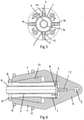
figure 8 . - Referring to the drawings, pipe handling apparatus comprises an outer substantially cylindrical tube 1, with a substantially annular cross-section, for receiving the end of a length of flexible pipe to be handled. One end of the tube is open and the other is closed. A
square flange 2 with curved corners extends around the open end. An aperture extends through the flange at each of its corners. Fourelongate slots 3 of substantially the same length are formed in the tube 1. The elongate slots extend parallel to the axis of the tube and are evenly spaced around its circumference. Eachslot 3 extends over about half the length of the tube from close to the open end of the tube. - An inner, substantially cylindrical, tube 4, with a substantially annular cross-section extends coaxially within the outer tube 1. The inner tube 1 has a closed end surrounded by a
circular flange 5. Theflange 5 abuts the closed end of the outer tube 1 andbolts 6 or other suitable fasteners extend through theflange 5 into the closed end of the outer tube 1 to mount the inner tube 4 within the outer tube. The opposite end of the inner tube 4 is open and extends slightly beyond theflange 2 of the outer tube. The wall of the part of the inner tube 4 which extends beyond theflange 2 of the outer tube is chamfered, so that its outside diameter reduces towards the end the of the tube. Fourelongate recesses 7 of substantially the same length are formed in the outside surface of the inner tube 4. Therecesses 7 extend parallel to the axis of the tube and are evenly spaced around its circumference. Eachrecess 7 is aligned with arespective slot 3 in the outer tube 1, is slightly longer than theslot 3 and positioned so that the recess extends axially beyond the end of both ends of the slot. Therecesses 7 have a generally concave cross-section and a depth which is substantially constant over the major part of the length of the indentation, gradually reducing at each end of the recess. - The outer tube 1 is mounted in a frame. The frame comprises two forked members, each formed from metal plate. The first forked 8 member has a generally triangular part with an
aperture 9 extending through it near to the apex of the triangle forming a lifting eye via which the apparatus, and any pipe to be handled by the apparatus, can be lifted. A parallel sided slot is cut into the base of the triangular part which accommodates the closed end of the outer tube 1 with a sliding fit. A narrower parallel sided slot is cut into the base of thisslot 10 into which the second forkedmember 13 is fixed, so that the second forkedmember 13 extends in a plane substantially at right angles to the first forked member. Two prongs 11 extend from the triangular part of the first forkedmember 8. The two prongs extend from respective opposite sides of the base of the triangular part and are angled to extend towards each other as they extend away from the base of the triangular part. The ends of the prongs 11 remote from the triangular part are fixed to a generallyannular ring 12. Thering 12 is formed from metal plate and extends in a plane perpendicular to that of the first forked member 11 and the axis of the outer 1 and inner 4 tubes. - The second forked
member 13 is similar in shape to the first forked member 11, save that it is missing an apex to the triangular shaped part which is, instead, trapezoidal in shape so as to be received into the narrower slot in the first forked member 11 so that it extends in a plane perpendicular to both the first forked member 11 and thering 12. Theprongs 14 of the second forked member are also connected to thering 12. The second forked member also receives the outer tube 1 with a sliding fit. - All four
prongs 11, 14 extend through a respective slot in asupport plate 15 to which they are fixed. Thesupport plate 15 is generally square with chamfered corners. An aperture is formed through the centre of the plate, through which the outer tube 1 extends, with the slots through which the prongs extend opening out into the aperture. Thesupport plate 15 is generally parallel to thering 12 and spaced from the ring to that is approximately half way along the length of the prongs. - A
respective clamping member 19 is slidably mounted to the face of eachprong 11, 14 which faces the outer tube 1. Each clamping member comprises an elongate metal plate with a tapering width. The two shorter sides of the plate are substantially parallel. One of the longer sides is substantially perpendicular to the two shorter sides. The thickness of the plate tapers towards this side forming a wedge shape terminating in a relatively narrow clamping edge andball bearings 20 are embedded in this edge. A groove is formed along the length of the opposite longer edge with the sides of the groove undercut to form twoopposed rails 21. Theserails 21 are received intorespective grooves 22 formed in opposite sides of eachprong 11, 14 adjacent, but spaced from, and parallel to, the inner edge of each prong. This formation serves to capture each clampingmember 19 into a respective prong and allows the clamping member to slide relative to the prong. The two longer sides of each clamping member extend at angle of approximately 20 degrees relative to each other, which corresponds to the angle at which the inner face of each prong extends relative to the axis of the outer tube. Consequently the inwardly directed edge of each clamping member, forming the clamping surface, extends parallel to the axis of the outer tube 1. - Each clamping
member 19 extends through a respectiveelongate slot 3 in the outer tube 1 with a close sliding fit. - Four
hydraulic cylinders 16 are mounted to the surface of thesupport plate 15 which faces thering 12, one between each adjacent pair ofprongs 11, 14, with the axis of each cylinder being parallel to the axis of the outer tube. Each hydraulic cylinder houses a piston connected to apiston rod 17 which extends through an aperture in thering 12 and is connected to thesquare flange 2 of the outer tube 1.Bolts 18 extend through the apertures in theflange 2 and into thepiston rods 17 to secure the rods to the ring. Thehydraulic cylinders 16 are operable to move theflange 2 and thus the outer tube 1 relative to the frame with theflange 2 remaining substantially parallel to thering 12. - When the pistons are fully retracted into the
cylinders 16 the outer tube 1 moves almost fully into the slots in the forkedmembers flange 2 approaches thering 12 as shown infigures 1 to 3 and6 . This constitutes the released state of the apparatus. When thecylinders 16 are energised and the pistons urged out of the cylinders to their fullest extent the outer tube 1 and the frame are urged away from each other into the position shown infigure 7 , the engaged state of the apparatus. - As the apparatus is moved between the released and engaged states the outer tube 1 is moved relative to the frame. As the clamping
members 19 extend through theslots 3 in the outer tube 1 they move axially with the tube, causing them to slide along theprongs 11, 14. The inner surfaces of the prongs act as cam surfaces. They approach the outer tube 1 as they approach thering 12. Thus, movement of the clampingmembers 19 along the prongs causes them to move radially too. When the apparatus is in the retracted state the clampingmembers 19 are at their radially outermost position. When the apparatus is in the engaged state the clamping members are in their radially innermost position at which their radially inner edges extend into therespective recesses 7 in the inner tube 4. - The apparatus is employed to handle pipes, especially flexible pipes formed from multiple layers of metal strands. The apparatus is particularly useful for recovering flexible pipes from a sea bed.
- In use, a
pipe 23 to be recovered is inserted over the inner tube 4 and into the outer tube 1 of the apparatus with the apparatus in the retracted state. The pipe is inserted sufficiently far so that it extends beyond therecesses 7 on the surface of the inner tube, and ideally is inserted so that it extends all the way to the closed end of the outer tube 1. - Then, the
hydraulic cylinders 16 are energised, by pressurising them with fluid from an external source, to urge the apparatus towards, and possibly into, the engaged state. This urges the clampingmembers 19 radially inwards towards the inner tube 4, causing the flexible pipe to be clamped between the clamping members and the inner tube. Owing to the force applied and the relatively narrow edge of the clampingmembers 19 the clamping members will tend to cut through any polymer layer(s) of the flexible pipe, typically an outer polymer sheath, and come into contact with the steel strands beneath, gripping them between the clamping members and theinner tube 2. The balls embedded in the clamping surfaces facilitate cutting through any polymer layers and in obtaining a firm grip on metal strands or other load bearing components of the flexible pipe. Thus load bearing components, particularly steel strands, of the flexible pipe are firmly gripped between the clamping members and the inner tube. As the clamping surfaces extend axially along the pipe a grip will be established on multiple different steel strands of the pipe, enabling a greater load of pipe to be supported. As the clamping members are urged towards the inner tube they will urge the flexible pipe into therecesses 7 in theinner tube 2 which further increases purchase on the pipe. - When the hydraulic cylinders have been energised 16 the pipe can be lifted by lifting the apparatus via the
aperture 9. - When the pipe has been recovered the apparatus can be released from the pipe by de-energising the
hydraulic cylinders 16 to return the apparatus to the retracted state releasing a grip on the pipe. - Because the apparatus grips pipe between components, i.e. between the clamping members and the
inner tube 2, flexibility of the pipe does not prevent a firm grip being made on the pipe which, in practice, enables masses of pipe of the order of hundreds of tonnes to be lifted using the apparatus. - The above embodiment is described by way of example only. Many variations are possible without departing from the scope of the invention as defined in the appended claims.
Claims (13)
- Pipe handling apparatus for recovering flexible pipes from a sea bed, comprising: an insert (4) configured to be inserted into a pipe (23) to be handled; a plurality of clamping members (19) moveably mounted relative to the insert (4); and an actuator operable to urge the clamping members towards the insert (4) such that the wall of the pipe (23) to be handled can be gripped between the clamping members (19) and the insert (4), characterised in that the clamping members (19) have elongate, axially extending, clamping surfaces arranged, in use, to extend along the length of the pipe being handled, and the insert (4) comprises a respective elongate, axially extending, recess (7) in its surface for each clamping member (19).
- Pipe handling apparatus as claimed in claim 1 wherein there are 3, 4, 5, 6, 7 or 8 clamping members (19).
- Pipe handling apparatus as claimed in either claim 1 or 2 wherein the clamping members (19) are disposed so that in use they contact the pipe (23) to be handled at positions circumferentially around the wall of the pipe (23).
- Pipe handling apparatus as claimed in claim 3 wherein the clamping surface comprises teeth, grooves or other formations to increase grip between the clamping member (19) and the pipe (23) to be handled.
- Pipe handling apparatus as claimed in claim 4 wherein the clamping surface comprises ball bearings (20).
- Pipe handling apparatus as claimed in any preceding claim wherein one, more or each clamping member (19) has a wedge-shaped profile.
- Pipe handling apparatus as claimed in any preceding claim wherein the insert (4) is substantially cylindrical.
- Pipe handling apparatus as claimed in claim 7 wherein the insert (4) is disposed substantially coaxially within an outer tube (1), so a space for receiving the pipe (23) to be handled is defined between the insert (4) and the outer tube (1).
- Pipe handling apparatus as claimed in claim 8 wherein one or more apertures are formed in a wall of the outer tube (1) and one, more or each clamping member (19) extends through, and is moveably relative to, a respective aperture towards and away from the insert (4).
- Pipe handling apparatus as claimed in claim 8 or 9 further comprising a frame which is movable relative to the outer tube (1), the frame comprising one or more cam surfaces and each clamping member (19) being in contact with a respective cam surface and arranged such that movement of the frame relative to the outer tube (1) causes the/or each clamping member (19) to move towards or away from the insert (4).
- Pipe handling apparatus as claimed in claim 10 where the actuator is disposed between the outer tube (1) and the frame to effect relative movement between the outer tube (1) and the frame.
- A flexible pipeline recovery tool comprising pipe handling apparatus as claimed in any preceding claim.
- A method of handling a flexible pipe comprising multiple layers of metal strands comprising the steps of:a. providing pipe handling apparatus as claimed in any of claims 1 to 11;b. introducing the insert (4) into an end of the pipe (23) to be handled; andc. operating the actuator thereby to grip the pipe (23).
Applications Claiming Priority (2)
| Application Number | Priority Date | Filing Date | Title |
|---|---|---|---|
| GB1606719.1A GB2549480B (en) | 2016-04-18 | 2016-04-18 | Pipe handling apparatus |
| PCT/GB2017/051064 WO2017182785A1 (en) | 2016-04-18 | 2017-04-18 | Pipe handling apparatus |
Publications (2)
| Publication Number | Publication Date |
|---|---|
| EP3446017A1 EP3446017A1 (en) | 2019-02-27 |
| EP3446017B1 true EP3446017B1 (en) | 2022-03-23 |
Family
ID=58745263
Family Applications (1)
| Application Number | Title | Priority Date | Filing Date |
|---|---|---|---|
| EP17724866.3A Active EP3446017B1 (en) | 2016-04-18 | 2017-04-18 | Pipe handling apparatus |
Country Status (5)
| Country | Link |
|---|---|
| US (1) | US10597262B2 (en) |
| EP (1) | EP3446017B1 (en) |
| BR (1) | BR112018071425B1 (en) |
| GB (1) | GB2549480B (en) |
| WO (1) | WO2017182785A1 (en) |
Families Citing this family (2)
| Publication number | Priority date | Publication date | Assignee | Title |
|---|---|---|---|---|
| US10844976B1 (en) | 2020-02-17 | 2020-11-24 | Trinity Bay Equipment Holdings, LLC | Methods and apparatus for pulling flexible pipe |
| US11142981B2 (en) * | 2020-03-03 | 2021-10-12 | Trinity Bay Equipment Holdings, LLC | Pipe pull head systems and methods |
Citations (2)
| Publication number | Priority date | Publication date | Assignee | Title |
|---|---|---|---|---|
| US1421266A (en) * | 1920-04-01 | 1922-06-27 | Fray A Loman | Rod and pipe grab for wells |
| US6311792B1 (en) * | 1999-10-08 | 2001-11-06 | Tesco Corporation | Casing clamp |
Family Cites Families (17)
| Publication number | Priority date | Publication date | Assignee | Title |
|---|---|---|---|---|
| US1528145A (en) * | 1923-02-07 | 1925-03-03 | Emmet N Davidson | Combination tubing socket |
| US3751932A (en) | 1972-02-16 | 1973-08-14 | Exxon Production Research Co | Recovery and repair of offshore pipelines |
| US4257719A (en) * | 1978-04-17 | 1981-03-24 | Vickers Limited | Underwater pipelines |
| US4580826A (en) * | 1984-02-17 | 1986-04-08 | Carver Herman C | Retrieval tool |
| US5188483A (en) | 1991-07-25 | 1993-02-23 | Shell Oil Company | Subsea pipeline recovery clamp |
| US5642912A (en) * | 1994-10-24 | 1997-07-01 | Tti Trenchless Technologies, Inc. | Pulling attachment for plastic pipe and slip lining head |
| US6142545A (en) * | 1998-11-13 | 2000-11-07 | Bj Services Company | Casing pushdown and rotating tool |
| US20040108739A1 (en) * | 2002-12-10 | 2004-06-10 | Beeman Robert S. | Whipstock retrieving overshot |
| GB0506406D0 (en) * | 2005-03-30 | 2005-05-04 | Crp Group Ltd | Connector |
| GB2424932A (en) * | 2005-04-06 | 2006-10-11 | Bsw Ltd | Gripping device with helically or randomly arranged members to avoid excessive grooving |
| US7503388B2 (en) * | 2006-10-26 | 2009-03-17 | Baker Hughes Incorporated | Circumferentially loaded slip-type overshot retrieval tool |
| US20090114398A1 (en) * | 2007-11-07 | 2009-05-07 | Frank's International, Inc. | Apparatus and Method for Gripping and/or Handling Tubulars |
| US8002032B2 (en) * | 2007-12-13 | 2011-08-23 | Blowout Tools, Inc. | Hydraulic overshot with removable setting and testing core |
| CN102322548B (en) * | 2011-05-26 | 2013-08-14 | 中国海洋石油总公司 | Dragging end enclosure for deep-sea oil and gas pipeline discarding and recovery operations |
| US9175524B2 (en) * | 2011-12-28 | 2015-11-03 | Tesco Corporation | Pipe drive sealing system and method |
| EP3572614B1 (en) * | 2013-12-06 | 2022-01-05 | Weatherford Technology Holdings, LLC | Tubular handling tool |
| GB201415044D0 (en) | 2014-08-26 | 2014-10-08 | Ftl Subsea Ltd | Clamp |
-
2016
- 2016-04-18 GB GB1606719.1A patent/GB2549480B/en active Active
-
2017
- 2017-04-18 US US16/095,305 patent/US10597262B2/en active Active
- 2017-04-18 EP EP17724866.3A patent/EP3446017B1/en active Active
- 2017-04-18 BR BR112018071425-9A patent/BR112018071425B1/en active IP Right Grant
- 2017-04-18 WO PCT/GB2017/051064 patent/WO2017182785A1/en not_active Ceased
Patent Citations (2)
| Publication number | Priority date | Publication date | Assignee | Title |
|---|---|---|---|---|
| US1421266A (en) * | 1920-04-01 | 1922-06-27 | Fray A Loman | Rod and pipe grab for wells |
| US6311792B1 (en) * | 1999-10-08 | 2001-11-06 | Tesco Corporation | Casing clamp |
Also Published As
| Publication number | Publication date |
|---|---|
| BR112018071425B1 (en) | 2022-09-20 |
| WO2017182785A1 (en) | 2017-10-26 |
| GB2549480B (en) | 2019-06-12 |
| US10597262B2 (en) | 2020-03-24 |
| US20190135588A1 (en) | 2019-05-09 |
| BR112018071425A2 (en) | 2019-02-05 |
| GB2549480A (en) | 2017-10-25 |
| EP3446017A1 (en) | 2019-02-27 |
Similar Documents
| Publication | Publication Date | Title |
|---|---|---|
| US9927058B2 (en) | Gripping apparatus and devices for plugging of pipes, orifices or connecting | |
| US9636789B2 (en) | Turbomachine bucket displacement apparatus and method of use | |
| EP2344716B1 (en) | Tubular handling device | |
| US11408549B2 (en) | Gripping apparatus and devices for plugging of pipes, orifices or connecting | |
| EP0218049A1 (en) | Sealing of tubular members | |
| US20130140839A1 (en) | Self-centering clamping device | |
| KR101913659B1 (en) | Device for chucking a bore of pipe | |
| AU2022231742B2 (en) | Gripping apparatus and devices for plugging of pipes, orifices or connecting | |
| RS60877B1 (en) | Modified die block for drilling rig floor wrench | |
| US10597262B2 (en) | Pipe handling apparatus | |
| US20080099205A1 (en) | Circumferentially loaded slip-type overshot retrieval tool | |
| RU2802883C2 (en) | Improved method of cutting pipe at a drill site and tool for its implementation | |
| US11391404B2 (en) | Gripping apparatus and devices for plugging of pipes, orifices or connecting |
Legal Events
| Date | Code | Title | Description |
|---|---|---|---|
| STAA | Information on the status of an ep patent application or granted ep patent |
Free format text: STATUS: UNKNOWN |
|
| STAA | Information on the status of an ep patent application or granted ep patent |
Free format text: STATUS: THE INTERNATIONAL PUBLICATION HAS BEEN MADE |
|
| PUAI | Public reference made under article 153(3) epc to a published international application that has entered the european phase |
Free format text: ORIGINAL CODE: 0009012 |
|
| STAA | Information on the status of an ep patent application or granted ep patent |
Free format text: STATUS: REQUEST FOR EXAMINATION WAS MADE |
|
| 17P | Request for examination filed |
Effective date: 20181011 |
|
| AK | Designated contracting states |
Kind code of ref document: A1 Designated state(s): AL AT BE BG CH CY CZ DE DK EE ES FI FR GB GR HR HU IE IS IT LI LT LU LV MC MK MT NL NO PL PT RO RS SE SI SK SM TR |
|
| AX | Request for extension of the european patent |
Extension state: BA ME |
|
| DAV | Request for validation of the european patent (deleted) | ||
| DAX | Request for extension of the european patent (deleted) | ||
| STAA | Information on the status of an ep patent application or granted ep patent |
Free format text: STATUS: EXAMINATION IS IN PROGRESS |
|
| 17Q | First examination report despatched |
Effective date: 20200313 |
|
| GRAP | Despatch of communication of intention to grant a patent |
Free format text: ORIGINAL CODE: EPIDOSNIGR1 |
|
| STAA | Information on the status of an ep patent application or granted ep patent |
Free format text: STATUS: GRANT OF PATENT IS INTENDED |
|
| RIC1 | Information provided on ipc code assigned before grant |
Ipc: B66C 1/48 20060101ALI20210225BHEP Ipc: B66C 1/44 20060101ALI20210225BHEP Ipc: F16L 1/20 20060101ALI20210225BHEP Ipc: F16L 1/16 20060101AFI20210225BHEP |
|
| INTG | Intention to grant announced |
Effective date: 20210324 |
|
| GRAJ | Information related to disapproval of communication of intention to grant by the applicant or resumption of examination proceedings by the epo deleted |
Free format text: ORIGINAL CODE: EPIDOSDIGR1 |
|
| STAA | Information on the status of an ep patent application or granted ep patent |
Free format text: STATUS: EXAMINATION IS IN PROGRESS |
|
| INTC | Intention to grant announced (deleted) | ||
| GRAP | Despatch of communication of intention to grant a patent |
Free format text: ORIGINAL CODE: EPIDOSNIGR1 |
|
| STAA | Information on the status of an ep patent application or granted ep patent |
Free format text: STATUS: GRANT OF PATENT IS INTENDED |
|
| INTG | Intention to grant announced |
Effective date: 20210927 |
|
| GRAJ | Information related to disapproval of communication of intention to grant by the applicant or resumption of examination proceedings by the epo deleted |
Free format text: ORIGINAL CODE: EPIDOSDIGR1 |
|
| STAA | Information on the status of an ep patent application or granted ep patent |
Free format text: STATUS: EXAMINATION IS IN PROGRESS |
|
| GRAP | Despatch of communication of intention to grant a patent |
Free format text: ORIGINAL CODE: EPIDOSNIGR1 |
|
| STAA | Information on the status of an ep patent application or granted ep patent |
Free format text: STATUS: GRANT OF PATENT IS INTENDED |
|
| INTC | Intention to grant announced (deleted) | ||
| GRAS | Grant fee paid |
Free format text: ORIGINAL CODE: EPIDOSNIGR3 |
|
| GRAA | (expected) grant |
Free format text: ORIGINAL CODE: 0009210 |
|
| STAA | Information on the status of an ep patent application or granted ep patent |
Free format text: STATUS: THE PATENT HAS BEEN GRANTED |
|
| INTG | Intention to grant announced |
Effective date: 20220127 |
|
| AK | Designated contracting states |
Kind code of ref document: B1 Designated state(s): AL AT BE BG CH CY CZ DE DK EE ES FI FR GB GR HR HU IE IS IT LI LT LU LV MC MK MT NL NO PL PT RO RS SE SI SK SM TR |
|
| REG | Reference to a national code |
Ref country code: GB Ref legal event code: FG4D |
|
| REG | Reference to a national code |
Ref country code: CH Ref legal event code: EP |
|
| REG | Reference to a national code |
Ref country code: IE Ref legal event code: FG4D |
|
| REG | Reference to a national code |
Ref country code: DE Ref legal event code: R096 Ref document number: 602017054899 Country of ref document: DE |
|
| REG | Reference to a national code |
Ref country code: AT Ref legal event code: REF Ref document number: 1477662 Country of ref document: AT Kind code of ref document: T Effective date: 20220415 |
|
| REG | Reference to a national code |
Ref country code: NL Ref legal event code: FP |
|
| REG | Reference to a national code |
Ref country code: NO Ref legal event code: T2 Effective date: 20220323 |
|
| REG | Reference to a national code |
Ref country code: LT Ref legal event code: MG9D |
|
| PG25 | Lapsed in a contracting state [announced via postgrant information from national office to epo] |
Ref country code: SE Free format text: LAPSE BECAUSE OF FAILURE TO SUBMIT A TRANSLATION OF THE DESCRIPTION OR TO PAY THE FEE WITHIN THE PRESCRIBED TIME-LIMIT Effective date: 20220323 Ref country code: RS Free format text: LAPSE BECAUSE OF FAILURE TO SUBMIT A TRANSLATION OF THE DESCRIPTION OR TO PAY THE FEE WITHIN THE PRESCRIBED TIME-LIMIT Effective date: 20220323 Ref country code: LT Free format text: LAPSE BECAUSE OF FAILURE TO SUBMIT A TRANSLATION OF THE DESCRIPTION OR TO PAY THE FEE WITHIN THE PRESCRIBED TIME-LIMIT Effective date: 20220323 Ref country code: HR Free format text: LAPSE BECAUSE OF FAILURE TO SUBMIT A TRANSLATION OF THE DESCRIPTION OR TO PAY THE FEE WITHIN THE PRESCRIBED TIME-LIMIT Effective date: 20220323 Ref country code: BG Free format text: LAPSE BECAUSE OF FAILURE TO SUBMIT A TRANSLATION OF THE DESCRIPTION OR TO PAY THE FEE WITHIN THE PRESCRIBED TIME-LIMIT Effective date: 20220623 |
|
| REG | Reference to a national code |
Ref country code: AT Ref legal event code: MK05 Ref document number: 1477662 Country of ref document: AT Kind code of ref document: T Effective date: 20220323 |
|
| PG25 | Lapsed in a contracting state [announced via postgrant information from national office to epo] |
Ref country code: LV Free format text: LAPSE BECAUSE OF FAILURE TO SUBMIT A TRANSLATION OF THE DESCRIPTION OR TO PAY THE FEE WITHIN THE PRESCRIBED TIME-LIMIT Effective date: 20220323 Ref country code: GR Free format text: LAPSE BECAUSE OF FAILURE TO SUBMIT A TRANSLATION OF THE DESCRIPTION OR TO PAY THE FEE WITHIN THE PRESCRIBED TIME-LIMIT Effective date: 20220624 Ref country code: FI Free format text: LAPSE BECAUSE OF FAILURE TO SUBMIT A TRANSLATION OF THE DESCRIPTION OR TO PAY THE FEE WITHIN THE PRESCRIBED TIME-LIMIT Effective date: 20220323 |
|
| PG25 | Lapsed in a contracting state [announced via postgrant information from national office to epo] |
Ref country code: SM Free format text: LAPSE BECAUSE OF FAILURE TO SUBMIT A TRANSLATION OF THE DESCRIPTION OR TO PAY THE FEE WITHIN THE PRESCRIBED TIME-LIMIT Effective date: 20220323 Ref country code: SK Free format text: LAPSE BECAUSE OF FAILURE TO SUBMIT A TRANSLATION OF THE DESCRIPTION OR TO PAY THE FEE WITHIN THE PRESCRIBED TIME-LIMIT Effective date: 20220323 Ref country code: RO Free format text: LAPSE BECAUSE OF FAILURE TO SUBMIT A TRANSLATION OF THE DESCRIPTION OR TO PAY THE FEE WITHIN THE PRESCRIBED TIME-LIMIT Effective date: 20220323 Ref country code: PT Free format text: LAPSE BECAUSE OF FAILURE TO SUBMIT A TRANSLATION OF THE DESCRIPTION OR TO PAY THE FEE WITHIN THE PRESCRIBED TIME-LIMIT Effective date: 20220725 Ref country code: ES Free format text: LAPSE BECAUSE OF FAILURE TO SUBMIT A TRANSLATION OF THE DESCRIPTION OR TO PAY THE FEE WITHIN THE PRESCRIBED TIME-LIMIT Effective date: 20220323 Ref country code: EE Free format text: LAPSE BECAUSE OF FAILURE TO SUBMIT A TRANSLATION OF THE DESCRIPTION OR TO PAY THE FEE WITHIN THE PRESCRIBED TIME-LIMIT Effective date: 20220323 Ref country code: CZ Free format text: LAPSE BECAUSE OF FAILURE TO SUBMIT A TRANSLATION OF THE DESCRIPTION OR TO PAY THE FEE WITHIN THE PRESCRIBED TIME-LIMIT Effective date: 20220323 Ref country code: AT Free format text: LAPSE BECAUSE OF FAILURE TO SUBMIT A TRANSLATION OF THE DESCRIPTION OR TO PAY THE FEE WITHIN THE PRESCRIBED TIME-LIMIT Effective date: 20220323 |
|
| REG | Reference to a national code |
Ref country code: DE Ref legal event code: R119 Ref document number: 602017054899 Country of ref document: DE |
|
| PG25 | Lapsed in a contracting state [announced via postgrant information from national office to epo] |
Ref country code: PL Free format text: LAPSE BECAUSE OF FAILURE TO SUBMIT A TRANSLATION OF THE DESCRIPTION OR TO PAY THE FEE WITHIN THE PRESCRIBED TIME-LIMIT Effective date: 20220323 Ref country code: IS Free format text: LAPSE BECAUSE OF FAILURE TO SUBMIT A TRANSLATION OF THE DESCRIPTION OR TO PAY THE FEE WITHIN THE PRESCRIBED TIME-LIMIT Effective date: 20220723 Ref country code: AL Free format text: LAPSE BECAUSE OF FAILURE TO SUBMIT A TRANSLATION OF THE DESCRIPTION OR TO PAY THE FEE WITHIN THE PRESCRIBED TIME-LIMIT Effective date: 20220323 |
|
| REG | Reference to a national code |
Ref country code: CH Ref legal event code: PL |
|
| REG | Reference to a national code |
Ref country code: BE Ref legal event code: MM Effective date: 20220430 |
|
| PLBE | No opposition filed within time limit |
Free format text: ORIGINAL CODE: 0009261 |
|
| STAA | Information on the status of an ep patent application or granted ep patent |
Free format text: STATUS: NO OPPOSITION FILED WITHIN TIME LIMIT |
|
| PG25 | Lapsed in a contracting state [announced via postgrant information from national office to epo] |
Ref country code: MC Free format text: LAPSE BECAUSE OF FAILURE TO SUBMIT A TRANSLATION OF THE DESCRIPTION OR TO PAY THE FEE WITHIN THE PRESCRIBED TIME-LIMIT Effective date: 20220323 Ref country code: LU Free format text: LAPSE BECAUSE OF NON-PAYMENT OF DUE FEES Effective date: 20220418 Ref country code: LI Free format text: LAPSE BECAUSE OF NON-PAYMENT OF DUE FEES Effective date: 20220430 Ref country code: DK Free format text: LAPSE BECAUSE OF FAILURE TO SUBMIT A TRANSLATION OF THE DESCRIPTION OR TO PAY THE FEE WITHIN THE PRESCRIBED TIME-LIMIT Effective date: 20220323 Ref country code: DE Free format text: LAPSE BECAUSE OF NON-PAYMENT OF DUE FEES Effective date: 20221103 Ref country code: CH Free format text: LAPSE BECAUSE OF NON-PAYMENT OF DUE FEES Effective date: 20220430 |
|
| PG25 | Lapsed in a contracting state [announced via postgrant information from national office to epo] |
Ref country code: BE Free format text: LAPSE BECAUSE OF NON-PAYMENT OF DUE FEES Effective date: 20220430 |
|
| 26N | No opposition filed |
Effective date: 20230102 |
|
| PG25 | Lapsed in a contracting state [announced via postgrant information from national office to epo] |
Ref country code: IE Free format text: LAPSE BECAUSE OF NON-PAYMENT OF DUE FEES Effective date: 20220418 |
|
| PG25 | Lapsed in a contracting state [announced via postgrant information from national office to epo] |
Ref country code: SI Free format text: LAPSE BECAUSE OF FAILURE TO SUBMIT A TRANSLATION OF THE DESCRIPTION OR TO PAY THE FEE WITHIN THE PRESCRIBED TIME-LIMIT Effective date: 20220323 |
|
| P01 | Opt-out of the competence of the unified patent court (upc) registered |
Effective date: 20230518 |
|
| PG25 | Lapsed in a contracting state [announced via postgrant information from national office to epo] |
Ref country code: IT Free format text: LAPSE BECAUSE OF FAILURE TO SUBMIT A TRANSLATION OF THE DESCRIPTION OR TO PAY THE FEE WITHIN THE PRESCRIBED TIME-LIMIT Effective date: 20220323 |
|
| PG25 | Lapsed in a contracting state [announced via postgrant information from national office to epo] |
Ref country code: HU Free format text: LAPSE BECAUSE OF FAILURE TO SUBMIT A TRANSLATION OF THE DESCRIPTION OR TO PAY THE FEE WITHIN THE PRESCRIBED TIME-LIMIT; INVALID AB INITIO Effective date: 20170418 |
|
| PG25 | Lapsed in a contracting state [announced via postgrant information from national office to epo] |
Ref country code: MK Free format text: LAPSE BECAUSE OF FAILURE TO SUBMIT A TRANSLATION OF THE DESCRIPTION OR TO PAY THE FEE WITHIN THE PRESCRIBED TIME-LIMIT Effective date: 20220323 Ref country code: CY Free format text: LAPSE BECAUSE OF FAILURE TO SUBMIT A TRANSLATION OF THE DESCRIPTION OR TO PAY THE FEE WITHIN THE PRESCRIBED TIME-LIMIT Effective date: 20220323 |
|
| PG25 | Lapsed in a contracting state [announced via postgrant information from national office to epo] |
Ref country code: TR Free format text: LAPSE BECAUSE OF FAILURE TO SUBMIT A TRANSLATION OF THE DESCRIPTION OR TO PAY THE FEE WITHIN THE PRESCRIBED TIME-LIMIT Effective date: 20220323 |
|
| PG25 | Lapsed in a contracting state [announced via postgrant information from national office to epo] |
Ref country code: MT Free format text: LAPSE BECAUSE OF FAILURE TO SUBMIT A TRANSLATION OF THE DESCRIPTION OR TO PAY THE FEE WITHIN THE PRESCRIBED TIME-LIMIT Effective date: 20220323 |
|
| PGFP | Annual fee paid to national office [announced via postgrant information from national office to epo] |
Ref country code: NL Payment date: 20250430 Year of fee payment: 9 |
|
| PGFP | Annual fee paid to national office [announced via postgrant information from national office to epo] |
Ref country code: GB Payment date: 20250423 Year of fee payment: 9 |
|
| PGFP | Annual fee paid to national office [announced via postgrant information from national office to epo] |
Ref country code: NO Payment date: 20250424 Year of fee payment: 9 |
|
| PGFP | Annual fee paid to national office [announced via postgrant information from national office to epo] |
Ref country code: FR Payment date: 20250424 Year of fee payment: 9 |