EP3445883B1 - A high temperature iron-chromium-aluminium alloy tube, a method of manufacturing the tube and a use of the tube as radiant tube - Google Patents
A high temperature iron-chromium-aluminium alloy tube, a method of manufacturing the tube and a use of the tube as radiant tube Download PDFInfo
- Publication number
- EP3445883B1 EP3445883B1 EP16795054.2A EP16795054A EP3445883B1 EP 3445883 B1 EP3445883 B1 EP 3445883B1 EP 16795054 A EP16795054 A EP 16795054A EP 3445883 B1 EP3445883 B1 EP 3445883B1
- Authority
- EP
- European Patent Office
- Prior art keywords
- tube
- high temperature
- chromium
- aluminium alloy
- temperature iron
- Prior art date
- Legal status (The legal status is an assumption and is not a legal conclusion. Google has not performed a legal analysis and makes no representation as to the accuracy of the status listed.)
- Active
Links
Images


Classifications
-
- B—PERFORMING OPERATIONS; TRANSPORTING
- B23—MACHINE TOOLS; METAL-WORKING NOT OTHERWISE PROVIDED FOR
- B23P—METAL-WORKING NOT OTHERWISE PROVIDED FOR; COMBINED OPERATIONS; UNIVERSAL MACHINE TOOLS
- B23P15/00—Making specific metal objects by operations not covered by a single other subclass or a group in this subclass
-
- B—PERFORMING OPERATIONS; TRANSPORTING
- B21—MECHANICAL METAL-WORKING WITHOUT ESSENTIALLY REMOVING MATERIAL; PUNCHING METAL
- B21C—MANUFACTURE OF METAL SHEETS, WIRE, RODS, TUBES, PROFILES OR LIKE SEMI-MANUFACTURED PRODUCTS OTHERWISE THAN BY ROLLING; AUXILIARY OPERATIONS USED IN CONNECTION WITH METAL-WORKING WITHOUT ESSENTIALLY REMOVING MATERIAL
- B21C37/00—Manufacture of metal sheets, rods, wire, tubes, profiles or like semi-manufactured products, not otherwise provided for; Manufacture of tubes of special shape
- B21C37/06—Manufacture of metal sheets, rods, wire, tubes, profiles or like semi-manufactured products, not otherwise provided for; Manufacture of tubes of special shape of tubes or metal hoses; Combined procedures for making tubes, e.g. for making multi-wall tubes
- B21C37/12—Making tubes or metal hoses with helically arranged seams
- B21C37/122—Making tubes or metal hoses with helically arranged seams with welded or soldered seams
-
- B—PERFORMING OPERATIONS; TRANSPORTING
- B21—MECHANICAL METAL-WORKING WITHOUT ESSENTIALLY REMOVING MATERIAL; PUNCHING METAL
- B21C—MANUFACTURE OF METAL SHEETS, WIRE, RODS, TUBES, PROFILES OR LIKE SEMI-MANUFACTURED PRODUCTS OTHERWISE THAN BY ROLLING; AUXILIARY OPERATIONS USED IN CONNECTION WITH METAL-WORKING WITHOUT ESSENTIALLY REMOVING MATERIAL
- B21C37/00—Manufacture of metal sheets, rods, wire, tubes, profiles or like semi-manufactured products, not otherwise provided for; Manufacture of tubes of special shape
- B21C37/06—Manufacture of metal sheets, rods, wire, tubes, profiles or like semi-manufactured products, not otherwise provided for; Manufacture of tubes of special shape of tubes or metal hoses; Combined procedures for making tubes, e.g. for making multi-wall tubes
- B21C37/12—Making tubes or metal hoses with helically arranged seams
-
- B—PERFORMING OPERATIONS; TRANSPORTING
- B21—MECHANICAL METAL-WORKING WITHOUT ESSENTIALLY REMOVING MATERIAL; PUNCHING METAL
- B21C—MANUFACTURE OF METAL SHEETS, WIRE, RODS, TUBES, PROFILES OR LIKE SEMI-MANUFACTURED PRODUCTS OTHERWISE THAN BY ROLLING; AUXILIARY OPERATIONS USED IN CONNECTION WITH METAL-WORKING WITHOUT ESSENTIALLY REMOVING MATERIAL
- B21C37/00—Manufacture of metal sheets, rods, wire, tubes, profiles or like semi-manufactured products, not otherwise provided for; Manufacture of tubes of special shape
- B21C37/06—Manufacture of metal sheets, rods, wire, tubes, profiles or like semi-manufactured products, not otherwise provided for; Manufacture of tubes of special shape of tubes or metal hoses; Combined procedures for making tubes, e.g. for making multi-wall tubes
- B21C37/08—Making tubes with welded or soldered seams
-
- B—PERFORMING OPERATIONS; TRANSPORTING
- B23—MACHINE TOOLS; METAL-WORKING NOT OTHERWISE PROVIDED FOR
- B23K—SOLDERING OR UNSOLDERING; WELDING; CLADDING OR PLATING BY SOLDERING OR WELDING; CUTTING BY APPLYING HEAT LOCALLY, e.g. FLAME CUTTING; WORKING BY LASER BEAM
- B23K26/00—Working by laser beam, e.g. welding, cutting or boring
- B23K26/20—Bonding
- B23K26/21—Bonding by welding
- B23K26/24—Seam welding
- B23K26/30—Seam welding of three-dimensional [3D] seams
- B23K26/302—Seam welding of three-dimensional [3D] seams of helicoidal seams
-
- B—PERFORMING OPERATIONS; TRANSPORTING
- B23—MACHINE TOOLS; METAL-WORKING NOT OTHERWISE PROVIDED FOR
- B23K—SOLDERING OR UNSOLDERING; WELDING; CLADDING OR PLATING BY SOLDERING OR WELDING; CUTTING BY APPLYING HEAT LOCALLY, e.g. FLAME CUTTING; WORKING BY LASER BEAM
- B23K9/00—Arc welding or cutting
- B23K9/02—Seam welding; Backing means; Inserts
- B23K9/032—Seam welding; Backing means; Inserts for three-dimensional [3D] seams
-
- B—PERFORMING OPERATIONS; TRANSPORTING
- B23—MACHINE TOOLS; METAL-WORKING NOT OTHERWISE PROVIDED FOR
- B23K—SOLDERING OR UNSOLDERING; WELDING; CLADDING OR PLATING BY SOLDERING OR WELDING; CUTTING BY APPLYING HEAT LOCALLY, e.g. FLAME CUTTING; WORKING BY LASER BEAM
- B23K9/00—Arc welding or cutting
- B23K9/02—Seam welding; Backing means; Inserts
- B23K9/032—Seam welding; Backing means; Inserts for three-dimensional [3D] seams
- B23K9/0325—Seam welding; Backing means; Inserts for three-dimensional [3D] seams helicoidal seams
-
- C—CHEMISTRY; METALLURGY
- C21—METALLURGY OF IRON
- C21D—MODIFYING THE PHYSICAL STRUCTURE OF FERROUS METALS; GENERAL DEVICES FOR HEAT TREATMENT OF FERROUS OR NON-FERROUS METALS OR ALLOYS; MAKING METAL MALLEABLE, e.g. BY DECARBURISATION OR TEMPERING
- C21D1/00—General methods or devices for heat treatment, e.g. annealing, hardening, quenching or tempering
- C21D1/26—Methods of annealing
- C21D1/30—Stress-relieving
-
- C—CHEMISTRY; METALLURGY
- C21—METALLURGY OF IRON
- C21D—MODIFYING THE PHYSICAL STRUCTURE OF FERROUS METALS; GENERAL DEVICES FOR HEAT TREATMENT OF FERROUS OR NON-FERROUS METALS OR ALLOYS; MAKING METAL MALLEABLE, e.g. BY DECARBURISATION OR TEMPERING
- C21D8/00—Modifying the physical properties of ferrous metals or ferrous alloys by deformation combined with, or followed by, heat treatment
- C21D8/10—Modifying the physical properties of ferrous metals or ferrous alloys by deformation combined with, or followed by, heat treatment during manufacturing of tubular bodies
-
- C—CHEMISTRY; METALLURGY
- C21—METALLURGY OF IRON
- C21D—MODIFYING THE PHYSICAL STRUCTURE OF FERROUS METALS; GENERAL DEVICES FOR HEAT TREATMENT OF FERROUS OR NON-FERROUS METALS OR ALLOYS; MAKING METAL MALLEABLE, e.g. BY DECARBURISATION OR TEMPERING
- C21D9/00—Heat treatment, e.g. annealing, hardening, quenching or tempering, adapted for particular articles; Furnaces therefor
- C21D9/08—Heat treatment, e.g. annealing, hardening, quenching or tempering, adapted for particular articles; Furnaces therefor for tubular bodies or pipes
-
- C—CHEMISTRY; METALLURGY
- C21—METALLURGY OF IRON
- C21D—MODIFYING THE PHYSICAL STRUCTURE OF FERROUS METALS; GENERAL DEVICES FOR HEAT TREATMENT OF FERROUS OR NON-FERROUS METALS OR ALLOYS; MAKING METAL MALLEABLE, e.g. BY DECARBURISATION OR TEMPERING
- C21D9/00—Heat treatment, e.g. annealing, hardening, quenching or tempering, adapted for particular articles; Furnaces therefor
- C21D9/50—Heat treatment, e.g. annealing, hardening, quenching or tempering, adapted for particular articles; Furnaces therefor for welded joints
-
- C—CHEMISTRY; METALLURGY
- C22—METALLURGY; FERROUS OR NON-FERROUS ALLOYS; TREATMENT OF ALLOYS OR NON-FERROUS METALS
- C22C—ALLOYS
- C22C38/00—Ferrous alloys, e.g. steel alloys
-
- C—CHEMISTRY; METALLURGY
- C22—METALLURGY; FERROUS OR NON-FERROUS ALLOYS; TREATMENT OF ALLOYS OR NON-FERROUS METALS
- C22C—ALLOYS
- C22C38/00—Ferrous alloys, e.g. steel alloys
- C22C38/001—Ferrous alloys, e.g. steel alloys containing N
-
- C—CHEMISTRY; METALLURGY
- C22—METALLURGY; FERROUS OR NON-FERROUS ALLOYS; TREATMENT OF ALLOYS OR NON-FERROUS METALS
- C22C—ALLOYS
- C22C38/00—Ferrous alloys, e.g. steel alloys
- C22C38/002—Ferrous alloys, e.g. steel alloys containing In, Mg, or other elements not provided for in one single group C22C38/001 - C22C38/60
-
- C—CHEMISTRY; METALLURGY
- C22—METALLURGY; FERROUS OR NON-FERROUS ALLOYS; TREATMENT OF ALLOYS OR NON-FERROUS METALS
- C22C—ALLOYS
- C22C38/00—Ferrous alloys, e.g. steel alloys
- C22C38/005—Ferrous alloys, e.g. steel alloys containing rare earths, i.e. Sc, Y, Lanthanides
-
- C—CHEMISTRY; METALLURGY
- C22—METALLURGY; FERROUS OR NON-FERROUS ALLOYS; TREATMENT OF ALLOYS OR NON-FERROUS METALS
- C22C—ALLOYS
- C22C38/00—Ferrous alloys, e.g. steel alloys
- C22C38/02—Ferrous alloys, e.g. steel alloys containing silicon
-
- C—CHEMISTRY; METALLURGY
- C22—METALLURGY; FERROUS OR NON-FERROUS ALLOYS; TREATMENT OF ALLOYS OR NON-FERROUS METALS
- C22C—ALLOYS
- C22C38/00—Ferrous alloys, e.g. steel alloys
- C22C38/04—Ferrous alloys, e.g. steel alloys containing manganese
-
- C—CHEMISTRY; METALLURGY
- C22—METALLURGY; FERROUS OR NON-FERROUS ALLOYS; TREATMENT OF ALLOYS OR NON-FERROUS METALS
- C22C—ALLOYS
- C22C38/00—Ferrous alloys, e.g. steel alloys
- C22C38/06—Ferrous alloys, e.g. steel alloys containing aluminium
-
- C—CHEMISTRY; METALLURGY
- C22—METALLURGY; FERROUS OR NON-FERROUS ALLOYS; TREATMENT OF ALLOYS OR NON-FERROUS METALS
- C22C—ALLOYS
- C22C38/00—Ferrous alloys, e.g. steel alloys
- C22C38/18—Ferrous alloys, e.g. steel alloys containing chromium
- C22C38/22—Ferrous alloys, e.g. steel alloys containing chromium with molybdenum or tungsten
-
- C—CHEMISTRY; METALLURGY
- C22—METALLURGY; FERROUS OR NON-FERROUS ALLOYS; TREATMENT OF ALLOYS OR NON-FERROUS METALS
- C22C—ALLOYS
- C22C38/00—Ferrous alloys, e.g. steel alloys
- C22C38/18—Ferrous alloys, e.g. steel alloys containing chromium
- C22C38/24—Ferrous alloys, e.g. steel alloys containing chromium with vanadium
-
- C—CHEMISTRY; METALLURGY
- C22—METALLURGY; FERROUS OR NON-FERROUS ALLOYS; TREATMENT OF ALLOYS OR NON-FERROUS METALS
- C22C—ALLOYS
- C22C38/00—Ferrous alloys, e.g. steel alloys
- C22C38/18—Ferrous alloys, e.g. steel alloys containing chromium
- C22C38/26—Ferrous alloys, e.g. steel alloys containing chromium with niobium or tantalum
-
- C—CHEMISTRY; METALLURGY
- C22—METALLURGY; FERROUS OR NON-FERROUS ALLOYS; TREATMENT OF ALLOYS OR NON-FERROUS METALS
- C22C—ALLOYS
- C22C38/00—Ferrous alloys, e.g. steel alloys
- C22C38/18—Ferrous alloys, e.g. steel alloys containing chromium
- C22C38/28—Ferrous alloys, e.g. steel alloys containing chromium with titanium or zirconium
-
- C—CHEMISTRY; METALLURGY
- C22—METALLURGY; FERROUS OR NON-FERROUS ALLOYS; TREATMENT OF ALLOYS OR NON-FERROUS METALS
- C22C—ALLOYS
- C22C38/00—Ferrous alloys, e.g. steel alloys
- C22C38/18—Ferrous alloys, e.g. steel alloys containing chromium
- C22C38/32—Ferrous alloys, e.g. steel alloys containing chromium with boron
-
- F—MECHANICAL ENGINEERING; LIGHTING; HEATING; WEAPONS; BLASTING
- F16—ENGINEERING ELEMENTS AND UNITS; GENERAL MEASURES FOR PRODUCING AND MAINTAINING EFFECTIVE FUNCTIONING OF MACHINES OR INSTALLATIONS; THERMAL INSULATION IN GENERAL
- F16S—CONSTRUCTIONAL ELEMENTS IN GENERAL; STRUCTURES BUILT-UP FROM SUCH ELEMENTS, IN GENERAL
- F16S3/00—Elongated members, e.g. profiled members; Assemblies thereof; Gratings or grilles
-
- B—PERFORMING OPERATIONS; TRANSPORTING
- B23—MACHINE TOOLS; METAL-WORKING NOT OTHERWISE PROVIDED FOR
- B23K—SOLDERING OR UNSOLDERING; WELDING; CLADDING OR PLATING BY SOLDERING OR WELDING; CUTTING BY APPLYING HEAT LOCALLY, e.g. FLAME CUTTING; WORKING BY LASER BEAM
- B23K2101/00—Articles made by soldering, welding or cutting
- B23K2101/04—Tubular or hollow articles
- B23K2101/06—Tubes
-
- B—PERFORMING OPERATIONS; TRANSPORTING
- B23—MACHINE TOOLS; METAL-WORKING NOT OTHERWISE PROVIDED FOR
- B23K—SOLDERING OR UNSOLDERING; WELDING; CLADDING OR PLATING BY SOLDERING OR WELDING; CUTTING BY APPLYING HEAT LOCALLY, e.g. FLAME CUTTING; WORKING BY LASER BEAM
- B23K2103/00—Materials to be soldered, welded or cut
- B23K2103/02—Iron or ferrous alloys
-
- B—PERFORMING OPERATIONS; TRANSPORTING
- B23—MACHINE TOOLS; METAL-WORKING NOT OTHERWISE PROVIDED FOR
- B23P—METAL-WORKING NOT OTHERWISE PROVIDED FOR; COMBINED OPERATIONS; UNIVERSAL MACHINE TOOLS
- B23P2700/00—Indexing scheme relating to the articles being treated, e.g. manufactured, repaired, assembled, connected or other operations covered in the subgroups
- B23P2700/09—Heat pipes
Definitions
- the present invention relates to a high temperature iron-chromium-aluminium alloy tube according to the preamble of claim 1 and to a method of manufacturing such a tube according to the preamble of the independent method claim.
- the present invention relates to said tube for use in heating applications and/or heating devices, such as a radiant tube, a muffle tube, a thermocouple protection tube, a retort tube, a furnace tube, etc.
- tubes of a material having high temperature resistance, high corrosion resistance and good thermal shock properties include e.g. ceramic tubes, silicon carbide tubes and nickel-chromium (NiCr) alloy-based tubes.
- NiCr nickel-chromium
- tubes made from iron-chromium-aluminium (FeCrAl) alloys offer several advantages compared to other tube materials, including an oxidation life and maximum working temperature that exceed by far those of most other materials, such as chromia forming alloys.
- FeCrAl alloys are the commercially available alloys sold under the trademarks Kanthal ® APM and Kanthal ® APMT and Kanthal ® AF.
- FeCrAl alloy tubes can be manufactured as seamless tubes by means of extrusion and as such provide excellent performance and service life in comparison with most other metallic high temperature tube alternatives, in particular under carburising conditions.
- the manufacturing process of such seamless tubes is relatively expensive and complicated and the resulting seamless tubes are therefore costly in comparison to other tubes used in the field.
- the welded high-temperature FeCrAl alloy tube according to the invention is suitable for use in heating applications, e.g. for use as a radiant tube in an electric heating device having a heating element in the form of a heating wire, as a muffle tube, a thermocouple protection tube, a retort tube, a furnace tube, etc.
- the high-temperature FeCrAl alloy tube as defined in claim 1 has a constant inner diameter or an almost constant inner diameter (d) along a longitudinal axis.
- inner diameter of the high-temperature FeCrAl alloy tube differs less than 10% from one end to the other end of the high-temperature FeCrAI tube.
- the tube has as defined in claim 1 a wall thickness of 0.5-4.5% of an inner diameter of the high-temperature FeCrAl alloy tube.
- the wall thickness may be thinner than, or of the same order as, the wall thickness of a corresponding extruded high-temperature FeCrAl alloy tube, which is normally around 5% of the inner diameter of the tube.
- the high-temperature FeCrAl alloy tube can thereby be used to replace an extruded seamless tube and achieve similar results.
- This thickness is thinner than the wall thickness of an extruded tube.
- the relatively thin tube walls will bind less thermal energy compared to thicker tube walls and thereby enable quicker heating of the tube and smaller thermal losses. This thin wall thickness is therefore advantageous for heating applications.
- a wall thickness of 2 mm can e.g. be achieved.
- the tube has a wall thickness of 0.5-3.5% of an inner diameter of the tube.
- the tube has a helical welded seam extending at a helix angle of 1 to 89° with respect to the longitudinal axis of the tube as defined in claim 1.
- increasing the helix angle means that a larger diameter of the high-temperature FeCrAl alloy tube can be achieved for the same width of the strip used to produce the tube.
- the helical welded seam extends at a helix angle of 25-75° with respect to the longitudinal axis of the high-temperature FeCrAl alloy tube.
- the helical welded seam extends at a helix angle of 40-70° with respect to the longitudinal axis of the tube.
- This is a typical helix angle interval for tubes having diameters between 70 mm and 500 mm, produced from strip having a width of between 160 mm and 540 mm.
- tubes wherein the helical welded seam extends at a helix angle within the interval 47-54° can e.g. be produced, with outer diameters within the range 93-108 mm.
- the high temperature iron-chromium-aluminium alloy of the inventive tube as defined hereinabove or hereinafter consists of:
- This alloy has excellent oxidation and corrosion resistance.
- the alloy may consist of other intentionally added alloying elements may be selected from Y, Zr, Hf, Ta, Th, Ti, Si, Mn, B, Sc, Ce, La, W, Nb, V, C, N, O, P and S, of which some elements may also be present in the form of normally occurring impurities.
- suitable alloys are iron-chromium-aluminium alloy sold under the trademarks Kanthal ® APM and Kanthal ® APMT and Kanthal ® AF.
- Chromium will promote the formation of the Al 2 O 3 layer on the high temperature FeCrAl alloy tube through the so-called third element effect, i.e. by formation of chromium oxide in the transient oxidation stage. Chromium shall be present in the alloy in an amount of at least 9 wt.%. However, too high amounts of Cr will promote the formation of intermetallic phases in the tube, therefore the highest amount of Cr is 25 wt.%. Thus, the amount of Cr is 9 to 25 wt.%. According to further embodiments, depending on application, the content of Cr is from 11 to 17 wt.% or 5 to 15 wt.% or 20.5 to 25 wt.% or 20.5 to 24 wt.%.
- Aluminum is an important element in the high temperature alloy as aluminum, when exposed to oxygen at high temperature, will form the dense and thin oxide Al 2 O 3 , which will protect the underlying alloy surface from further oxidation.
- the amount of aluminum should be at least 2.5 wt.% to ensure that the Al 2 O 3 layer is formed and that sufficient aluminum is present to heal the Al 2 O 3 layer when damaged.
- aluminum has a negative impact on the formability of the alloy and the amount of aluminum should not exceed 8 wt.% in the alloy as defined hereinabove or hereinafter.
- the content of aluminum is 2.5 to 8 wt.%, such as 3 - 7 wt.%, such as 3 - 5 wt.%, such as 4 to 6 wt.%, such as 5 to 7 wt.%.
- unavoidable impurities are the balance.
- unavoidable impurities' is meant elements which are not added by purpose and which does not have any influence on the properties of the alloy.
- the high temperature FeCrAl alloy also consist of the following elements:
- Molybdenum has positive effects on the hot-strength of the high temperature FeCrAl alloy in an amount up to 4.0 wt.%. According to embodiments the content of Mo may be from 1.0 to 4.0 wt.%.
- Silicon may be present as an impurity or it may be added to the high temperature FeCrAl alloy. If it is an impurity, the amount may not be more than 0.7 wt.%. If added purposely, the amounts is - 0.70 wt.%;
- Manganese may be present in the high temperature FeCrAl alloy in amount of from 0 to 0.4 wt.%.
- Carbon may be included in the high temperature FeCrAl alloy to increase strength by precipitation hardening. Carbon may also be present as an unavoidable impurity resulting from the production process. To achieve sufficient strength in the alloy, carbon should be present in an amount of at least 0.01 wt.%. At too high levels, carbon may result in difficulties to form the material and a negative effect on the corrosion resistance, the maximum amount of carbon is therefore 0.1 wt.%.
- the FeCrAl alloy consist of such 0.01 to 0.8 wt.% C,
- Scandium, Cerium, and Lanthanum are interchangeable elements and may be added individually or in combination in a total amount of up to 0.2 wt.% to improve oxidation properties, self-healing of the Al 2 O 3 layer or the adhesion between the alloy and the Al 2 O 3 layer.
- Oxygen may exist in the high temperature FeCrAl alloy as an impurity resulting from the production process in amounts up to 0.02 wt.%, Oxygen may be deliberately added to achieve a precipitation hardening effect.
- the high temperature FeCrAl alloy then comprises up to 0.1 wt.% oxygen.
- Nitrogen may be included in the high temperature FeCrAl alloy to increase strength by precipitation hardening. Nitrogen may also be present as an unavoidable impurity resulting from the production process. At too high levels, nitrogen may result in difficulties to form the material and may have a negative effect on the corrosion resistance. Therefore, the maximum amount of nitrogen is 0.1 wt.% in the FeCrAl alloy as defined hereinabove or hereinafter. To achieve sufficient precipitation hardening in melt metallurgy, nitrogen should be at least 0.001 wt.%, examples of suitable ranges of nitrogen is for example 0.001 - 0.1 wt.%, such as 0.01 - 0.6 wt.%.
- the reactive elements are highly reactive with carbon, nitrogen and oxygen.
- Titanium (Ti), Zirconium (Zr), Niobium (Nb), Vanadium (V), Hafnium (Hf), Tantalum (Ta), Yttrium (Y) and Thorium (Th) are reactive elements in the sense that they have high affinity to carbon, thus being strong carbide formers. These elements may be added in order to improve the oxidation properties of the high temperature FeCrAl alloy by balancing the diffusion of metal ions and oxygen, which will govern the kinetics of the oxide growth process.
- the maximum amounts of respective reactive element will depend mainly on tendency of the element to form adverse intermetallic phases. Hence, the maximum amount of titanium is 1.7 wt.% in the alloy as defined hereinabove or hereinafter, such as 0.02 -1.7 wt.%, such as 0-0.10 wt.%.
- the maximum amount of zirconium and niobium is 0.8 wt.% in.
- Example of amounts of zirconium is 0 to 0.4 wt.%, such as of from 0.1 to 0.3 wt.%.
- Examples of amounts of niobium may be of from 0 - 0.4 wt.%, suchas 0.1 to 0.3 wt.%.
- Yttrium may be added in an amount up to 2.2 wt.%, such as of from 0.01 to 0.60 wt.%, such as 0.05 to 0.60 wt.% in order to improve the adherence of the Al 2 O 3 layer.
- the addition of yttrium must be balance with the amount of other carbide former elements present in the high temperature FeCrAl alloy.
- the maximum amount of vanadium is 0.1 wt.%; Hafnium, tantalum and thorium are interchangeable elements and may be added to in up to 1 wt.%
- the high temperature iron-chromium-aluminium alloy consist of one or more elements selected from:
- the high temperature iron-chromium-aluminium alloy additionally consists of one or more elements selected from:
- Tubes according to this embodiment will have good form stability at high temperature and the alloys will form a non-scaling surface oxide providing good protection in most high temperature environments including oxidising, sulphurous and carburising environments. The surface oxide will also provide excellent protection against deposits of carbon, ash, etc. Tubes according to this embodiment will also exhibit superior resistance to e.g. thermal shock, sagging and distortion, due to a superior hot strength and creep rupture strength in comparison with other known FeCrAl alloys. In particular, this is the case for FeCrAl alloys according to this embodiment produced by powder metallurgy.
- the present disclosure relates to said high temperature FeCrAI tube for use in heating applications and/or heating devices, such as a radiant tube, a muffle tube, a thermocouple protection tube, a retort tube, a furnace tube, etc.
- the present disclosure relates to a straight tube which is to be vertically installed.
- the present invention relates to a method of manufacturing a high temperature iron-chromium-aluminium alloy tube as initially defined, wherein said method comprises the steps of:
- the inner diameter (d) of the high temperature iron-chromium-aluminium alloy tube is constant or almost constant along a longitudinal axis.
- a welded seam in the form of a butt joint weld is formed, extending at a helix angle around the high temperature iron-chromium-aluminium alloy tube and along its full length.
- an annealing to relieve stresses is optionally carried out and the tube is thereafter cut into final length.
- the method of manufacturing is cost efficient and produces a high temperature FeCrAl alloy tube with properties that are in at least some aspects comparable to those of a corresponding extruded seamless tube, in particular with regard to corrosion and oxidation resistance and load bearing for applications in which the tube is to be vertically mounted, i.e. with its longitudinal axis is extending in a vertical direction.
- Using continuous strip as a starting material for producing the high temperature FeCrAl alloy tube enables production of a large range of final dimensions.
- a high temperature iron-chromium-aluminium alloy tube according to any one of the above described embodiments can be manufactured using the proposed method of manufacturing.
- the method enables formation of tubes with thinner walls in comparison with extruded tubes with similar diameter.
- the proposed method will also enable high temperature iron-chromium-aluminium alloy tube with larger diameter to be manufactured in comparison with extruded tubes.
- the welding process is selected from a fusion welding process or a solid state joining process. Both fusion welding processes and solid state joining processes are suitable for creating a strong and reliable welded seam.
- the welding process may be carried out using a welding electrode positioned radially outside of the formed tube.
- the welding may also be carried out from inside of the formed tube, or from both the outside and the inside. Carrying out the welding from outside of the formed tube is an easy and efficient way of obtaining a welded joint of sufficient depth for thin-walled strips, i.e. for wall thicknesses of less than approximately 5 mm. For larger wall thicknesses, welding from both the inside and the outside of the tube may be necessary in order to obtain a sufficiently strong welded joint.
- the welding process is selected from one of a tungsten inert gas welding process, a metal inert gas welding process (MIG), a laser welding process, and a plasma arc welding process.
- tungsten inert gas welding TAG or GTAW
- GTAW tungsten inert gas welding
- a shielding gas is used during the welding process, which shielding gas is an inert gas.
- the inert gas protects the material from forming aluminium nitrides, and also oxides, along the welded seam. Nitrides and oxides formed during welding may otherwise impair the oxidation resistance of the tube, and thereby also its desirable properties for high temperature applications.
- the shielding gas consists of Ar (argon), He (helium), or a mixture thereof.
- no filler material is used in the welding process.
- a filler material comprising an iron-chromium-aluminium alloy is used in the welding process.
- the method may further comprise a step of preheating the continuously strip prior to forming the tube. Preheating up to e.g. 100°C or less makes the strip easier to deform into a tube and is particularly suitable for smaller dimensions, such as for tube with inner diameters of less than 100 mm.
- the preheating can be achieved using e.g. a furnace, induction heating means, a heat gun, or similar.
- the method further comprises the step of annealing the high temperature iron-chromium-aluminium alloy tube subsequently to the welding process.
- the annealing may relieve stress in the welded tube and thereby contribute to cracking prevention.
- the annealing is a stress relieving annealing performed in-line in a tube forming apparatus in which the tube is also wound and welded. The tube is heated to a temperature of 850-875°C and is thereafter allowed to cool before being cut into final length.
- a high temperature iron-chromium-aluminium (FeCrAl) alloy tube 1 is schematically shown in fig. 1-3 .
- the tube 1 is in the form of a circular cylinder extending along a longitudinal axis C.
- the high temperature iron-chromium-aluminium alloy tube 1 is formed with a helical welded seam 2 extending around and along the tube at a helix angle a.
- the helix angle ⁇ is 54°.
- the shown tube 1 has an outer diameter D of 108 mm, a length L and a wall thickness t of 2 mm, thus having an inner diameter d of 104 mm.
- the inner diameter d is constant along the longitudinal axis C.
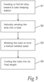
- the tube 1 is formed from a continuous strip 3 of high temperature FeCrAl alloy using spiral welding, as schematically illustrated in fig. 4 and in the flow chart in fig. 5 .
- a continuous strip 3 of the high temperature FeCrAl alloy having a width w, is fed in a feeding direction X toward a tube shaping station 4, which is here in the form of three shaping rolls 5.
- the shaping rolls 5 are arranged with their axes of rotation at an angle with respect to the feeding direction X of the strip 3.
- a third step S3 the abutting long edges 6, 7 are continuously joined together in a welding process directly when the tube is formed, whereby the welded tube 1 comprising the helical welded seam 2 is obtained.
- the welding process is in the shown embodiment carried out using a welding electrode 8 positioned radially outside of the formed tube 1.
- the welded seam 2 is created with a welding root on an inside of the formed tube 1.
- the welding may be carried out using e.g. tungsten inert gas (TIG) welding, metal inert gas welding, laser welding, or plasma arc welding.
- TOG tungsten inert gas
- metal inert gas welding metal inert gas welding
- laser welding or plasma arc welding.
- a shielding gas during the welding process an inert gas such as Ar and/or He is used.
- a root gas consisting of Ar and/or He may be used to protect the root during welding.
- a fourth step S4 the tube 1 is cut into its final length L.
- the strip 3 may be preheated up to a temperature of 100°C or less before being wound into a tube 1.
- the formed tube 1 may furthermore be annealed after welding, before or after cutting the tube 1 into its final length L. During the annealing process, the tube 1 is heated to a temperature of 850-875°C and is thereafter allowed to cool.
- a tube 1 as described with reference to fig. 1-3 above was produced from a strip having a width w of 200 mm and a thickness t of 2 mm.
- the chemical composition of the strip is shown in table 1.
- the welding process performed was a TIG process without filler material and with a gas mixture of 70% Ar and 30% He, which was used as both a root gas and a shielding gas.
- the welding was carried out from outside of the formed tube 1. No support was used on the inside of the tube 1 during welding.
- the welded high temperature FeCrAl alloy tube 1 was cut into a final length L of 3 m using an angle grinder, without annealing prior to cutting. After cutting into test specimens (tubes) of final length and cooling of the welded seam 2, one of the test specimens 1 was annealed for 1 h at 875°C.
- the welded seam 2 had a good appearance directly after welding, on the inside of the tube 1 as well as on the outside.
- the welded seam 2 was concave on the outside and convex on the inside.
- Cross sections across the welded seam 2 were visually inspected using light optical microscopy after etching and polishing. No defects were found during the inspection.
- the hardness HV10 was investigated across the welded seam 2 and was found to be between 220 and 265 HV across the welded seam, with the highest value in the base material next to the welded seam.
- test specimens Two other test specimens were pre-oxidised at 1050°C for 8h and were thereafter tested in a furnace, mounted vertically with 80 mm diameter cartridge heating elements (26 kW at 200 V voltage) mounted inside the tubes.
- test specimens were subjected to a continuous cycling for one week according to the following scheme:
- test specimen was put at the bottom of the furnace to study whether the weight of the test specimen would result in any deformation during exposure, i.e. a simplified sag test. This test specimen showed no tendency to be distorted during the 18 days exposure.
Landscapes
- Chemical & Material Sciences (AREA)
- Engineering & Computer Science (AREA)
- Mechanical Engineering (AREA)
- Materials Engineering (AREA)
- Metallurgy (AREA)
- Organic Chemistry (AREA)
- Physics & Mathematics (AREA)
- Thermal Sciences (AREA)
- Crystallography & Structural Chemistry (AREA)
- Plasma & Fusion (AREA)
- Optics & Photonics (AREA)
- Manufacturing & Machinery (AREA)
- General Engineering & Computer Science (AREA)
- Child & Adolescent Psychology (AREA)
- Health & Medical Sciences (AREA)
- Heat Treatment Of Articles (AREA)
- Butt Welding And Welding Of Specific Article (AREA)
- Arc Welding In General (AREA)
- Rigid Pipes And Flexible Pipes (AREA)
- Bending Of Plates, Rods, And Pipes (AREA)
Description
- The present invention relates to a high temperature iron-chromium-aluminium alloy tube according to the preamble of
claim 1 and to a method of manufacturing such a tube according to the preamble of the independent method claim. In particular, but not exclusively, the present invention relates to said tube for use in heating applications and/or heating devices, such as a radiant tube, a muffle tube, a thermocouple protection tube, a retort tube, a furnace tube, etc. - In heating applications, such as in gas-heated or electrically heated furnaces and in heating devices, it is common to use tubes of a material having high temperature resistance, high corrosion resistance and good thermal shock properties. Such tubes include e.g. ceramic tubes, silicon carbide tubes and nickel-chromium (NiCr) alloy-based tubes. In oxidising environments at working temperatures exceeding 1100°C, tubes made from iron-chromium-aluminium (FeCrAl) alloys offer several advantages compared to other tube materials, including an oxidation life and maximum working temperature that exceed by far those of most other materials, such as chromia forming alloys. This is mostly due to the capability of forming a dense and adherent alumina film that protects the FeCrAl material against corrosion and atmospheric attack. Examples of such FeCrAl alloys are the commercially available alloys sold under the trademarks Kanthal® APM and Kanthal® APMT and Kanthal® AF.
- FeCrAl alloy tubes can be manufactured as seamless tubes by means of extrusion and as such provide excellent performance and service life in comparison with most other metallic high temperature tube alternatives, in particular under carburising conditions. However, the manufacturing process of such seamless tubes is relatively expensive and complicated and the resulting seamless tubes are therefore costly in comparison to other tubes used in the field. Additionally, there are limitations in manufacturing processes in regard of how large (diameter) tube can be manufactured and also the how thin the wall thickness can be.
- Examples of tubes and manufacturing processes are mentioned in
JP 2012 115890 CN 102 330 034 . However, the tubes mentioned therein do not provide a solution to the present problems. The articles "Thermal Alloys Engineering: Protection Tubes in FeCrAl-Alloys for High Temperature Service", (20110201), * : and Karl-Heinz Brensing ET AL, "Steel Tube and Pipe Manufacturing Process", (19941231), pages 1 - 63, page 55 - page 58 also disclose tubes and manufacturing processes but do not provide a solution to the present problems. - In view of the above-mentioned problems, it is desirable to provide a high temperature FeCrAl alloy tube which is less costly and easier to produce and which also may have a large diameter and/or thin wall thickness, but which still has superior properties in terms of oxidation and corrosion resistance and which will thereby achieve a long service life.
- This is achieved by means of the initially defined high temperature iron-chromium-aluminium (FeCrAl) alloy tube as set out in the appended set of claims, wherein the tube is formed from a continuous strip of iron -chromium-aluminium alloy and comprises a helical welded seam. The obtained high temperature iron-chromium-aluminium alloy tube will have oxidation and corrosion resistances which are very similar to those of a corresponding seamless tube, produced from the similar material. Furthermore, since the proposed tube can be produced by spiral welding from a continuous strip of high temperature FeCrAl material instead of by extrusion, the tube is less costly and easier to produce and may also have larger diameter and/or thinner wall thickness. By means of the proposed tube, excellent oxidation and corrosion resistance at a competitive price can thereby be achieved. According to the present disclosure, the term "high temperature" is meant temperatures above 300 °C, such as above 400 °C, such as above 500 °C.
- The welded high-temperature FeCrAl alloy tube according to the invention is suitable for use in heating applications, e.g. for use as a radiant tube in an electric heating device having a heating element in the form of a heating wire, as a muffle tube, a thermocouple protection tube, a retort tube, a furnace tube, etc.
- The high-temperature FeCrAl alloy tube as defined in
claim 1 has a constant inner diameter or an almost constant inner diameter (d) along a longitudinal axis. By the term "almost constant diameter" is meant that the inner diameter of the high-temperature FeCrAl alloy tube differs less than 10% from one end to the other end of the high-temperature FeCrAI tube. - The tube has as defined in claim 1 a wall thickness of 0.5-4.5% of an inner diameter of the high-temperature FeCrAl alloy tube. Thus, the wall thickness may be thinner than, or of the same order as, the wall thickness of a corresponding extruded high-temperature FeCrAl alloy tube, which is normally around 5% of the inner diameter of the tube. The high-temperature FeCrAl alloy tube can thereby be used to replace an extruded seamless tube and achieve similar results. This thickness is thinner than the wall thickness of an extruded tube. The relatively thin tube walls will bind less thermal energy compared to thicker tube walls and thereby enable quicker heating of the tube and smaller thermal losses. This thin wall thickness is therefore advantageous for heating applications. For a tube having an inner diameter of around 100 mm, which is a common dimension for radiant tubes used in heating applications such as with electrical cartridge heating elements, a wall thickness of 2 mm can e.g. be achieved. In one embodiment, the tube has a wall thickness of 0.5-3.5% of an inner diameter of the tube.
- The tube has a helical welded seam extending at a helix angle of 1 to 89° with respect to the longitudinal axis of the tube as defined in
claim 1. Generally, increasing the helix angle means that a larger diameter of the high-temperature FeCrAl alloy tube can be achieved for the same width of the strip used to produce the tube. - According to one embodiment, the helical welded seam extends at a helix angle of 25-75° with respect to the longitudinal axis of the high-temperature FeCrAl alloy tube.
- According to one embodiment, the helical welded seam extends at a helix angle of 40-70° with respect to the longitudinal axis of the tube. This is a typical helix angle interval for tubes having diameters between 70 mm and 500 mm, produced from strip having a width of between 160 mm and 540 mm. For tubes produced from strip having a width of 200 mm, tubes wherein the helical welded seam extends at a helix angle within the interval 47-54° can e.g. be produced, with outer diameters within the range 93-108 mm.
- The high temperature iron-chromium-aluminium alloy of the inventive tube as defined hereinabove or hereinafter consists of:
- 9-25 wt.% Cr;
- 2.5-8 wt.% Al;
- 0-4 wt.% Mo;
- and one or more elements selected from:
- 0.01 - 0.08 wt.% C;
- 0 - 0.7 wt.% Si;
- 0 - 0.4 wt.% Mn;
- and optionally one or more elements selected from the group of
- 0.05-0.60 wt.% Y;
- 0.01-0.40 wt.% Zr;
- 0.05-0.50 wt.% Hf;
- 0.05-0.50 wt.% Ta;
- 0-0.10 wt.% Ti;
- 0.01-0.06 wt.% N;
- 0.02-0.10 wt.% O;
- 0-0.08 wt.% P;
- 0-0.005 wt.% S;
or - one or more elements selected from the group of 0.001-0.1 wt.% N;
- 0.02-0.10 wt.% O;
- 0-0.01 wt.% B;
- 0-0.5 wt.% Mn;
- 0-2.2 wt.% Y;
- 0-0.2 wt.% Sc+Ce+La;
- 0-1.7 wt.% Ti;
- 0-0.4 wt.% Zr:
0-0.4 wt.% Nb:
0-0.1 wt.% V:
0-0.3 wt.% Hf+Ta+Th;
- the balance being Fe and normally occurring impurities. This alloy has excellent oxidation and corrosion resistance.
- As mentioned above, the alloy may consist of other intentionally added alloying elements may be selected from Y, Zr, Hf, Ta, Th, Ti, Si, Mn, B, Sc, Ce, La, W, Nb, V, C, N, O, P and S, of which some elements may also be present in the form of normally occurring impurities. Examples of suitable alloys are iron-chromium-aluminium alloy sold under the trademarks Kanthal® APM and Kanthal® APMT and Kanthal® AF.
- The constituents of the high temperature FeCrAl alloy will in the following be described in detail.
- Chromium will promote the formation of the Al2O3 layer on the high temperature FeCrAl alloy tube through the so-called third element effect, i.e. by formation of chromium oxide in the transient oxidation stage. Chromium shall be present in the alloy in an amount of at least 9 wt.%. However, too high amounts of Cr will promote the formation of intermetallic phases in the tube, therefore the highest amount of Cr is 25 wt.%. Thus, the the amount of Cr is 9 to 25 wt.%. According to further embodiments, depending on application, the content of Cr is from 11 to 17 wt.% or 5 to 15 wt.% or 20.5 to 25 wt.% or 20.5 to 24 wt.%.
- Aluminum is an important element in the high temperature alloy as aluminum, when exposed to oxygen at high temperature, will form the dense and thin oxide Al2O3, which will protect the underlying alloy surface from further oxidation. The amount of aluminum should be at least 2.5 wt.% to ensure that the Al2O3 layer is formed and that sufficient aluminum is present to heal the Al2O3 layer when damaged. However, aluminum has a negative impact on the formability of the alloy and the amount of aluminum should not exceed 8 wt.% in the alloy as defined hereinabove or hereinafter. Thus, the content of aluminum is 2.5 to 8 wt.%, such as 3 - 7 wt.%, such as 3 - 5 wt.%, such as 4 to 6 wt.%, such as 5 to 7 wt.%.
- Iron (Fe) and unavoidable impurities are the balance. By the term "unavoidable impurities'" is meant elements which are not added by purpose and which does not have any influence on the properties of the alloy.
- The high temperature FeCrAl alloy also consist of the following elements:
- Molybdenum has positive effects on the hot-strength of the high temperature FeCrAl alloy in an amount up to 4.0 wt.%. According to embodiments the content of Mo may be from 1.0 to 4.0 wt.%.
- Silicon may be present as an impurity or it may be added to the high temperature FeCrAl alloy. If it is an impurity, the amount may not be more than 0.7 wt.%. If added purposely, the amounts is - 0.70 wt.%;
- Manganese may be present in the high temperature FeCrAl alloy in amount of from 0 to 0.4 wt.%.
- Carbon may be included in the high temperature FeCrAl alloy to increase strength by precipitation hardening. Carbon may also be present as an unavoidable impurity resulting from the production process. To achieve sufficient strength in the alloy, carbon should be present in an amount of at least 0.01 wt.%. At too high levels, carbon may result in difficulties to form the material and a negative effect on the corrosion resistance, the maximum amount of carbon is therefore 0.1 wt.%. The FeCrAl alloy consist of such 0.01 to 0.8 wt.% C,
- The high temperature FeCrAl alloy as defined in the claims may also consist of the following elements as stated in the appended set of claims:
- Scandium, Cerium, and Lanthanum are interchangeable elements and may be added individually or in combination in a total amount of up to 0.2 wt.% to improve oxidation properties, self-healing of the Al2O3 layer or the adhesion between the alloy and the Al2O3 layer.
- Oxygen may exist in the high temperature FeCrAl alloy as an impurity resulting from the production process in amounts up to 0.02 wt.%, Oxygen may be deliberately added to achieve a precipitation hardening effect. The high temperature FeCrAl alloy then comprises up to 0.1 wt.% oxygen.
- Nitrogen may be included in the high temperature FeCrAl alloy to increase strength by precipitation hardening. Nitrogen may also be present as an unavoidable impurity resulting from the production process. At too high levels, nitrogen may result in difficulties to form the material and may have a negative effect on the corrosion resistance. Therefore, the maximum amount of nitrogen is 0.1 wt.% in the FeCrAl alloy as defined hereinabove or hereinafter. To achieve sufficient precipitation hardening in melt metallurgy, nitrogen should be at least 0.001 wt.%, examples of suitable ranges of nitrogen is for example 0.001 - 0.1 wt.%, such as 0.01 - 0.6 wt.%.
- Per definition, the reactive elements are highly reactive with carbon, nitrogen and oxygen. Titanium (Ti), Zirconium (Zr), Niobium (Nb), Vanadium (V), Hafnium (Hf), Tantalum (Ta), Yttrium (Y) and Thorium (Th) are reactive elements in the sense that they have high affinity to carbon, thus being strong carbide formers. These elements may be added in order to improve the oxidation properties of the high temperature FeCrAl alloy by balancing the diffusion of metal ions and oxygen, which will govern the kinetics of the oxide growth process. The maximum amounts of respective reactive element will depend mainly on tendency of the element to form adverse intermetallic phases. Hence, the maximum amount of titanium is 1.7 wt.% in the alloy as defined hereinabove or hereinafter, such as 0.02 -1.7 wt.%, such as 0-0.10 wt.%.
- The maximum amount of zirconium and niobium is 0.8 wt.% in. Example of amounts of zirconium is 0 to 0.4 wt.%, such as of from 0.1 to 0.3 wt.%. Examples of amounts of niobium may be of from 0 - 0.4 wt.%, suchas 0.1 to 0.3 wt.%.
- Yttrium may be added in an amount up to 2.2 wt.%, such as of from 0.01 to 0.60 wt.%, such as 0.05 to 0.60 wt.% in order to improve the adherence of the Al2O3 layer. However, the addition of yttrium must be balance with the amount of other carbide former elements present in the high temperature FeCrAl alloy.
- The maximum amount of vanadium is 0.1 wt.%;
Hafnium, tantalum and thorium are interchangeable elements and may be added to in up to 1 wt.% - Hence, the high temperature iron-chromium-aluminium alloy consist of one or more elements selected from:
- 0.01 - 0.08 wt.% C;
- 0 - 0.7 wt.% Si;
- 0 - 0.4 wt.% Mn.
- According to one embodiment, the high temperature iron-chromium-aluminium alloy additionally consists of one or more elements selected from:
- 0.05-0.60 wt.% Y;
- 0.01-0.40 wt.% Zr;
- 0.05-0.50 wt.% Hf;
- 0.05-0.50 wt.% Ta;
- 0-0.10 wt.% Ti;
- 0.01-0.05 wt.% C;
- 0.01-0.06 wt.% N;
- 0.02-0.10 wt.% O;
- 0.05-0.50 wt.% Mn;
- 0-0.8 wt. % P;
- 0-0.005 wt.% S.
- According to one embodiment, the high temperature iron-chromium-aluminium alloy additionally consists of one or more elements selected from:
- 0.01-0.1 wt.% C;
- 0.001-0.1 wt.% N;
- 0.02-0.10 wt.% O;
- 0-0.01 wt.% B;
- 0-0.5 wt.% Mn;
- 0-2.2 wt.% Y;
- 0-0.2 wt.% Sc+Ce+La;
- 0-1.7 wt.% Ti;
- 0-0.40 wt.% Zr;
- 0-0.4 wt.% Nb;
- 0-0.1 wt.% V;
- 0-0.3 wt.% Hf+Ta+Th.
- Examples of the high temperature FeCrAl alloys mentioned herein are e.g. disclosed in
WO2001/049441 . Tubes according to this embodiment will have good form stability at high temperature and the alloys will form a non-scaling surface oxide providing good protection in most high temperature environments including oxidising, sulphurous and carburising environments. The surface oxide will also provide excellent protection against deposits of carbon, ash, etc. Tubes according to this embodiment will also exhibit superior resistance to e.g. thermal shock, sagging and distortion, due to a superior hot strength and creep rupture strength in comparison with other known FeCrAl alloys. In particular, this is the case for FeCrAl alloys according to this embodiment produced by powder metallurgy. - However, it should be noted that some of the high temperature FeCrAl alloys mentioned herein may be manufactured conventionally, i.e. without using powder metallurgy.
- In particular, but not exclusively, the present disclosure relates to said high temperature FeCrAI tube for use in heating applications and/or heating devices, such as a radiant tube, a muffle tube, a thermocouple protection tube, a retort tube, a furnace tube, etc. In particular, but not exclusively, the present disclosure relates to a straight tube which is to be vertically installed.
- According to another aspect, the present invention relates to a method of manufacturing a high temperature iron-chromium-aluminium alloy tube as initially defined, wherein said method comprises the steps of:
- feeding a continuous strip of an iron-chromium-aluminium alloy toward a tube shaping station,
- helically winding the strip in the tube shaping station such that long edges of the strip abut each other and a rotating tube moving forward in a direction parallel to its longitudinal axis is formed,
- continuously joining said abutting long edges together in a welding process directly when the tube is formed, whereby a welded tube comprising a helical welded seam is obtained.
- It was surprisingly found that the high temperature FeCrAl alloy tubes manufactured according to the present method kept their form and length after welding. Additionally, after the high temperature FeCrAl alloy tubes had been manufactured, no cracks were seen during cooling.
- According to one embodiment of the present method, the inner diameter (d) of the high temperature iron-chromium-aluminium alloy tube is constant or almost constant along a longitudinal axis. A welded seam in the form of a butt joint weld is formed, extending at a helix angle around the high temperature iron-chromium-aluminium alloy tube and along its full length. After forming and welding the high temperature iron-chromium-aluminium alloy tube, an annealing to relieve stresses is optionally carried out and the tube is thereafter cut into final length. The method of manufacturing is cost efficient and produces a high temperature FeCrAl alloy tube with properties that are in at least some aspects comparable to those of a corresponding extruded seamless tube, in particular with regard to corrosion and oxidation resistance and load bearing for applications in which the tube is to be vertically mounted, i.e. with its longitudinal axis is extending in a vertical direction. Using continuous strip as a starting material for producing the high temperature FeCrAl alloy tube enables production of a large range of final dimensions.
- A high temperature iron-chromium-aluminium alloy tube according to any one of the above described embodiments can be manufactured using the proposed method of manufacturing. The method enables formation of tubes with thinner walls in comparison with extruded tubes with similar diameter. Furthermore, the proposed method will also enable high temperature iron-chromium-aluminium alloy tube with larger diameter to be manufactured in comparison with extruded tubes.
- According to one embodiment, the welding process is selected from a fusion welding process or a solid state joining process. Both fusion welding processes and solid state joining processes are suitable for creating a strong and reliable welded seam.
- The welding process may be carried out using a welding electrode positioned radially outside of the formed tube. The welding may also be carried out from inside of the formed tube, or from both the outside and the inside. Carrying out the welding from outside of the formed tube is an easy and efficient way of obtaining a welded joint of sufficient depth for thin-walled strips, i.e. for wall thicknesses of less than approximately 5 mm. For larger wall thicknesses, welding from both the inside and the outside of the tube may be necessary in order to obtain a sufficiently strong welded joint.
- According to one embodiment, the welding process is selected from one of a tungsten inert gas welding process, a metal inert gas welding process (MIG), a laser welding process, and a plasma arc welding process. In particular, tungsten inert gas welding (TIG or GTAW) enables formation of a strong, high quality welded seam.
- According to one embodiment, a shielding gas is used during the welding process, which shielding gas is an inert gas. The inert gas protects the material from forming aluminium nitrides, and also oxides, along the welded seam. Nitrides and oxides formed during welding may otherwise impair the oxidation resistance of the tube, and thereby also its desirable properties for high temperature applications.
- According to one embodiment, the shielding gas consists of Ar (argon), He (helium), or a mixture thereof.
- According to one embodiment, no filler material is used in the welding process.
- According to one embodiment, a filler material comprising an iron-chromium-aluminium alloy is used in the welding process.
- According to one embodiment, the method may further comprise a step of preheating the continuously strip prior to forming the tube. Preheating up to e.g. 100°C or less makes the strip easier to deform into a tube and is particularly suitable for smaller dimensions, such as for tube with inner diameters of less than 100 mm. The preheating can be achieved using e.g. a furnace, induction heating means, a heat gun, or similar.
- According to one embodiment, the method further comprises the step of annealing the high temperature iron-chromium-aluminium alloy tube subsequently to the welding process. The annealing may relieve stress in the welded tube and thereby contribute to cracking prevention. In one embodiment, the annealing is a stress relieving annealing performed in-line in a tube forming apparatus in which the tube is also wound and welded. The tube is heated to a temperature of 850-875°C and is thereafter allowed to cool before being cut into final length.
- Other advantageous features as well as advantages of the proposed tube and method of manufacturing will appear from the following description.
- Embodiments of the proposed high temperature FeCrAl alloy tube and method of manufacturing will in the following be described with reference to the appended drawings, in which
- Fig. 1
- schematically shows a perspective view of a tube according to an embodiment,
- Fig. 2
- shows a side view of the tube in
fig. 1 , - Fig. 3
- shows an end view of the tube in
fig. 1 , - Fig. 4
- schematically shows a method of manufacturing the tube in
fig. 1 , and - Fig. 5
- is a flow chart illustrating steps of a method of manufacturing a tube according to an embodiment.
- A high temperature iron-chromium-aluminium (FeCrAl)
alloy tube 1 according to an embodiment of the present invention is schematically shown infig. 1-3 . Thetube 1 is in the form of a circular cylinder extending along a longitudinal axis C. The high temperature iron-chromium-aluminium alloy tube 1 is formed with a helical weldedseam 2 extending around and along the tube at a helix angle a. In the shown embodiment, the helix angle α is 54°. The showntube 1 has an outer diameter D of 108 mm, a length L and a wall thickness t of 2 mm, thus having an inner diameter d of 104 mm. The inner diameter d is constant along the longitudinal axis C. - The
tube 1 is formed from acontinuous strip 3 of high temperature FeCrAl alloy using spiral welding, as schematically illustrated infig. 4 and in the flow chart infig. 5 . In a first step S1, acontinuous strip 3 of the high temperature FeCrAl alloy, having a width w, is fed in a feeding direction X toward atube shaping station 4, which is here in the form of three shaping rolls 5. The shaping rolls 5 are arranged with their axes of rotation at an angle with respect to the feeding direction X of thestrip 3. - When the
strip 3 enters between the shaping rolls 5, it is in a second step S2 helically wound into atube 1, withlong edges strip 3 abutting each other. A rotating tube is formed, moving forward in a direction parallel to its longitudinal axis C. - In a third step S3, the abutting
long edges tube 1 comprising the helical weldedseam 2 is obtained. The welding process is in the shown embodiment carried out using awelding electrode 8 positioned radially outside of the formedtube 1. Thus, the weldedseam 2 is created with a welding root on an inside of the formedtube 1. The welding may be carried out using e.g. tungsten inert gas (TIG) welding, metal inert gas welding, laser welding, or plasma arc welding. As a shielding gas during the welding process, an inert gas such as Ar and/or He is used. Also a root gas consisting of Ar and/or He may be used to protect the root during welding. - In a fourth step S4, the
tube 1 is cut into its final length L. - The
strip 3 may be preheated up to a temperature of 100°C or less before being wound into atube 1. The formedtube 1 may furthermore be annealed after welding, before or after cutting thetube 1 into its final length L. During the annealing process, thetube 1 is heated to a temperature of 850-875°C and is thereafter allowed to cool. - The present invention is further illustrated by the following nonlimiting example:
- For production of test specimens, a
tube 1 as described with reference tofig. 1-3 above was produced from a strip having a width w of 200 mm and a thickness t of 2 mm. The chemical composition of the strip is shown in table 1.Table 1 C Si Mn Cr Al Fe Nominal composition 5.3 Bal. Min - - - 20.5 Max 0.08 0.7 0.4 23.5 - The welding process performed was a TIG process without filler material and with a gas mixture of 70% Ar and 30% He, which was used as both a root gas and a shielding gas. The welding was carried out from outside of the formed
tube 1. No support was used on the inside of thetube 1 during welding. The welded high temperatureFeCrAl alloy tube 1 was cut into a final length L of 3 m using an angle grinder, without annealing prior to cutting. After cutting into test specimens (tubes) of final length and cooling of the weldedseam 2, one of thetest specimens 1 was annealed for 1 h at 875°C. - The welded
seam 2 had a good appearance directly after welding, on the inside of thetube 1 as well as on the outside. The weldedseam 2 was concave on the outside and convex on the inside. Cross sections across the weldedseam 2 were visually inspected using light optical microscopy after etching and polishing. No defects were found during the inspection. - The hardness HV10 was investigated across the welded
seam 2 and was found to be between 220 and 265 HV across the welded seam, with the highest value in the base material next to the welded seam. - Two other test specimens were pre-oxidised at 1050°C for 8h and were thereafter tested in a furnace, mounted vertically with 80 mm diameter cartridge heating elements (26 kW at 200 V voltage) mounted inside the tubes.
- The test specimens were subjected to a continuous cycling for one week according to the following scheme:
- Heating from room temperature up to 950°C;
- 20 min holding time at 950°C;
- Cooling to 600°C;
- Heating up to 950°C;
- 20 min holding time; etc.
- After one week, the test specimens looked very well upon visual inspection and the testing was continued for another 18 days with a tougher testing cycle. This testing cycle was carried out according to the following scheme:
- Heating from room temperature up to 950°;
- 20 min holding time at 950°C;
- Cooling to 100°C;
- Heating up to 950°C; etc.
- Visual inspection showed that the test specimens looked very fine.
- In addition, another test specimen was put at the bottom of the furnace to study whether the weight of the test specimen would result in any deformation during exposure, i.e. a simplified sag test. This test specimen showed no tendency to be distorted during the 18 days exposure.
Claims (11)
- A high temperature iron-chromium-aluminium alloy tube (1) extending along a longitudinal axis (C),
characterised inthat the tube (1) is formed from a continuous strip (3) of iron-chromium-aluminium alloy and that the tube (1) comprises a helical welded seam (2) and in that the tube (1) has almost a constant inner diameter (d) differing less than 10% from one end to the other end of the high-temperature FeCrAl tube or a constant inner diameter (d)along a longitudinal axis (C) and in that the high temperature iron-chromium-aluminium alloy consisting of:9-25 wt.% Cr;2.5-8 wt.% Al;0-4 wt.% Mo;and one or more elements selected from:0.01 - 0.08 wt.% C;0 - 0.7 wt.% Si;0 - 0.4 wt.% Mn;and optionally one or more elements selected from the group of0.05-0.60 wt.% Y;0.01-0.40 wt.% Zr;0.05-0.50 wt.% Hf;0.05-0.50 wt.% Ta;0-0.10 wt.% Ti;0.01-0.06 wt.% N;0.02-0.10 wt.% O;0-0.08 wt.% P;0-0.005 wt.% S;
orone or more elements selected from the group of0.001-0.1 wt.% N;0.02-0.10 wt.% O;0-0.01 wt.% B;0-0.5 wt.% Mn;0-2.2 wt.% Y;0-0.2 wt.% Sc+Ce+La;0-1.7 wt.% Ti;0-0.4 wt.% Zr:
0-0.4 wt.% Nb:
0-0.1 wt.% V:
0-0.3 wt.% Hf+Ta+Th;the balance being Fe and normally occurring impurities,and wherein the tube (1) has a wall thickness (t) of 0.5-4.5% of an inner diameter (d) of the tube (1) andwherein the helical welded seam (2) extends at a helix angle (a) of 1 to 89° with respect to the longitudinal axis (C) of the tube (1). - The high temperature iron-chromium-aluminium alloy tube according to claim 1, wherein the helical welded seam (2) extends at a helix angle (a) of 40-70° with respect to the longitudinal axis (C) of the tube (1).
- The high temperature iron-chromium-aluminium alloy tube according to any one of the preceding items, wherein content of Cr in the high temperature iron-chromium-aluminium alloy is of from 11 to 17 wt.% or of from 5 to 15 wt.% or of from 20.5 to 25 wt.%.
- The high temperature iron-chromium-aluminium alloy tube according to any one of the preceding claims, wherein content of Al in the high temperature iron-chromium-aluminium alloy is more than 3 to 7 wt.% or of from 4 to 6 wt.% or of from 5 to 7 wt.%.
- The high temperature iron-chromium-aluminium alloy tube according to any preceding claims, wherein content of Mo in the high temperature iron-chromium-aluminium alloy is of from 1 to 4 wt.%.
- The high temperature iron-chromium-aluminium alloy tube according to any preceding claims, wherein content of Si in the high temperature iron-chromium-aluminium alloy is of from 0.10-0.70 wt.%.
- A method of manufacturing a high temperature iron-chromium-aluminium alloy tube (1) having almost a constant or almost constant inner diameter extending along a longitudinal axis (C), according to any one of claim 1 to 6 characterised in that it comprises the steps of:- feeding a continuous strip (3) of a high temperature iron-chromium-aluminium alloy toward a tube shaping station (4),- helically winding the strip (3) in the tube shaping station (4) such that long edges (6, 7) of the strip (3) abut each other and a rotating tube (1) moving forward in a direction parallel to its longitudinal axis (C) is formed,- continuously joining said abutting long edges (6, 7) together in a welding process directly when the high temperature FeCrAl alloy tube (1) is formed, whereby a welded high temperature FeCrAl alloy tube (1) comprising a helical welded seam (2) is obtained and comprising the step of annealing the high temperature FeCrAl alloy tube (1) subsequently to the welding process.
- The method according to claim 7, wherein the welding process is selected from a fusion welding process or a solid state joining process or is selected from one of a tungsten inert gas welding process, a metal inert gas welding process, a laser welding process, and a plasma arc welding process.
- The method according to any one of claims 7-8, wherein a shielding gas is used during the welding process, which shielding gas is an inert gas.
- The method according to any one of claims 7-9, further comprising the step of preheating the strip (3) prior to forming the high temperature FeCrAl alloy tube (1).
- Use of a high temperature iron-chromium-aluminium alloy tube according to any one of claim 1 to 10 as a radiant tube in an electric heating device having a heating element in the form of a heating wire, as a muffle tube, a thermocouple protection tube, a retort tube, a furnace tube.
Applications Claiming Priority (2)
| Application Number | Priority Date | Filing Date | Title |
|---|---|---|---|
| EP16166659 | 2016-04-22 | ||
| PCT/EP2016/077544 WO2017182111A1 (en) | 2016-04-22 | 2016-11-14 | A tube and a method of manufacturing a tube |
Publications (3)
| Publication Number | Publication Date |
|---|---|
| EP3445883A1 EP3445883A1 (en) | 2019-02-27 |
| EP3445883B1 true EP3445883B1 (en) | 2024-10-02 |
| EP3445883C0 EP3445883C0 (en) | 2024-10-02 |
Family
ID=55967028
Family Applications (1)
| Application Number | Title | Priority Date | Filing Date |
|---|---|---|---|
| EP16795054.2A Active EP3445883B1 (en) | 2016-04-22 | 2016-11-14 | A high temperature iron-chromium-aluminium alloy tube, a method of manufacturing the tube and a use of the tube as radiant tube |
Country Status (13)
| Country | Link |
|---|---|
| US (3) | US11446722B2 (en) |
| EP (1) | EP3445883B1 (en) |
| JP (1) | JP6909806B2 (en) |
| KR (2) | KR20240011234A (en) |
| CN (2) | CN109072369A (en) |
| AU (3) | AU2016403428A1 (en) |
| BR (1) | BR112018071651B1 (en) |
| CA (1) | CA3020413A1 (en) |
| ES (1) | ES2989841T3 (en) |
| PL (1) | PL3445883T3 (en) |
| RU (1) | RU2732395C2 (en) |
| SG (1) | SG11201808855UA (en) |
| WO (1) | WO2017182111A1 (en) |
Families Citing this family (14)
| Publication number | Priority date | Publication date | Assignee | Title |
|---|---|---|---|---|
| WO2018129256A1 (en) * | 2017-01-06 | 2018-07-12 | Keystone Tower Systems, Inc. | Tube stiffening |
| CN109737735B (en) * | 2018-12-26 | 2021-01-01 | 合肥恒力装备有限公司 | Manufacturing method of powder material high-temperature calcination rotary furnace tube |
| DE102019211936A1 (en) * | 2019-02-01 | 2020-08-06 | Sms Group Gmbh | Screw seam tube and method for producing a screw seam tube |
| CN109719156B (en) * | 2019-03-06 | 2020-09-25 | 马鞍山欧格萨斯机械科技有限公司 | Efficient steel belt pipe production method |
| CN110026448B (en) * | 2019-04-30 | 2021-08-03 | 西安理工大学 | Integrally formed spiral stiffener steel pipe and forming method |
| WO2020247862A1 (en) * | 2019-06-05 | 2020-12-10 | Birla Carbon U.S.A., Inc. | High temperature carbon black air preheater |
| CN111440993B (en) * | 2019-12-12 | 2021-06-18 | 广东省钢铁研究所 | A kind of iron-chromium-aluminum alloy bar and preparation method thereof |
| CN111250561B (en) * | 2020-01-27 | 2021-09-24 | 浙江联丰冷却塔有限公司 | Automatic processing equipment for water distribution pipe of cooling tower |
| KR102483274B1 (en) * | 2020-06-05 | 2023-01-02 | 엄지은 | Billet for extrusion of multi-layer pipes and manufacturing method of multi-layer pipes using the same |
| CN112275832B (en) * | 2020-09-22 | 2022-08-05 | 盐城仕博机械制造有限公司 | Spiral duct machine |
| CN113784469A (en) * | 2021-03-05 | 2021-12-10 | 泰州市泰然装备有限公司 | A kind of material for high-temperature electrothermal radiation spiral outer tube and preparation method |
| CN113714321B (en) * | 2021-07-28 | 2022-10-25 | 西安交通大学 | Refractory and rare noble metal pipe and preparation method thereof |
| CN115780969A (en) * | 2022-11-17 | 2023-03-14 | 西安西材三川智能制造有限公司 | Argon arc welding process for iron-chromium-aluminum alloy pipeline |
| CN119571137A (en) * | 2024-11-26 | 2025-03-07 | 山东森塔电气科技有限公司 | Production process for increasing resistance of heating wire and shortening heating joint |
Family Cites Families (23)
| Publication number | Priority date | Publication date | Assignee | Title |
|---|---|---|---|---|
| DE1452226A1 (en) * | 1965-11-03 | 1969-01-23 | Benteler Werke Ag | Steel pipe manufacture |
| JPS5328014B2 (en) * | 1973-05-21 | 1978-08-11 | ||
| JPS5278612A (en) * | 1975-10-29 | 1977-07-02 | Nippon Steel Corp | Austenite-based heat-resistant steel capable of forming film of a#o# a t high temperatures in oxidizing atmosphere |
| US4204862A (en) | 1975-10-29 | 1980-05-27 | Nippon Steel Corporation | Austenitic heat-resistant steel which forms Al2 O3 film in high-temperature oxidizing atmosphere |
| JPS5914532B2 (en) | 1976-08-27 | 1984-04-05 | 松下電器産業株式会社 | alloy magnet |
| SU780923A1 (en) * | 1978-07-17 | 1980-11-23 | Предприятие П/Я А-1147 | Method of producing high-strength thin-walled helical seam tubes |
| CN1093758A (en) | 1993-04-16 | 1994-10-19 | 山东工业大学 | Cast 1300-1350 ℃ of iron-based high temperature steel and founding |
| JP3397092B2 (en) * | 1996-09-11 | 2003-04-14 | 住友金属工業株式会社 | Al-containing austenitic stainless steel with excellent hot workability |
| SE9702909L (en) | 1997-08-12 | 1998-10-19 | Sandvik Ab | Use of a ferritic Fe-Cr-Al alloy in the manufacture of compound tubes, as well as compound tubes and the use of the tubes |
| SE513989C2 (en) | 2000-01-01 | 2000-12-11 | Sandvik Ab | Process for manufacturing a FeCrAl material and such a mortar |
| JP2002363704A (en) * | 2001-06-12 | 2002-12-18 | Nippon Steel Corp | Corrosion-resistant steel with excellent toughness of base metal and weld heat affected zone |
| JP2008100261A (en) * | 2006-10-19 | 2008-05-01 | Jfe Steel Kk | Manufacturing method of spiral steel pipe with rib |
| EP2031080B1 (en) | 2007-08-30 | 2012-06-27 | Alstom Technology Ltd | High temperature alloy |
| CN100547103C (en) | 2007-12-10 | 2009-10-07 | 华油钢管有限公司 | A manufacturing method of high-strength X80 steel spiral welded pipe |
| FR2930463B1 (en) * | 2008-04-25 | 2010-09-03 | Faurecia Sys Echappement | DEVICE FOR MANUFACTURING A HELICOIDAL TUBE AND ASSOCIATED METHOD |
| DE102009031576A1 (en) * | 2008-07-23 | 2010-03-25 | V&M Deutschland Gmbh | Steel alloy for a ferritic steel with excellent creep rupture strength and oxidation resistance at elevated service temperatures |
| JP5321493B2 (en) * | 2010-02-12 | 2013-10-23 | 新日鐵住金株式会社 | Spiral steel pipe manufacturing method and spiral steel pipe |
| JP2012115890A (en) * | 2010-12-03 | 2012-06-21 | Nippon Steel Corp | Spiral steel pipe having varied diametric sections in longitudinal direction and method and device for manufacturing the same |
| CN102162064A (en) | 2011-05-08 | 2011-08-24 | 山西太钢不锈钢股份有限公司 | Iron-chromium-aluminum alloy and strip coil thereof |
| CN102330034B (en) * | 2011-09-30 | 2013-04-24 | 中国石油集团渤海石油装备制造有限公司 | X65MS steel-grade spiral welded tube for acidic corrosion environment and manufacturing method thereof |
| CN103192234B (en) | 2013-04-01 | 2015-07-15 | 宝鸡石油钢管有限责任公司 | Spiral molded large-deformation-resistant submerged-arc welding pipe and manufacture method thereof |
| EP3010680A4 (en) * | 2013-06-18 | 2017-03-08 | Sandvik Intellectual Property AB | Filler for the welding of materials for high-temperature applications |
| CN103484788B (en) | 2013-08-31 | 2016-05-04 | 宝鸡石油钢管有限责任公司 | A kind of high-strength X 80 MS spiral submerged welded pipe and manufacture method thereof of hydrogen sulfide corrosion-resistant |
-
2016
- 2016-11-14 RU RU2018140820A patent/RU2732395C2/en active
- 2016-11-14 KR KR1020247000746A patent/KR20240011234A/en not_active Ceased
- 2016-11-14 ES ES16795054T patent/ES2989841T3/en active Active
- 2016-11-14 CN CN201680084721.2A patent/CN109072369A/en active Pending
- 2016-11-14 US US16/093,679 patent/US11446722B2/en active Active
- 2016-11-14 AU AU2016403428A patent/AU2016403428A1/en not_active Abandoned
- 2016-11-14 WO PCT/EP2016/077544 patent/WO2017182111A1/en not_active Ceased
- 2016-11-14 KR KR1020187033452A patent/KR20180133506A/en not_active Ceased
- 2016-11-14 PL PL16795054.2T patent/PL3445883T3/en unknown
- 2016-11-14 BR BR112018071651-0A patent/BR112018071651B1/en active IP Right Grant
- 2016-11-14 EP EP16795054.2A patent/EP3445883B1/en active Active
- 2016-11-14 CN CN202411246030.0A patent/CN119035991A/en active Pending
- 2016-11-14 JP JP2018555151A patent/JP6909806B2/en active Active
- 2016-11-14 CA CA3020413A patent/CA3020413A1/en active Pending
- 2016-11-14 SG SG11201808855UA patent/SG11201808855UA/en unknown
-
2022
- 2022-07-08 US US17/860,859 patent/US11602780B2/en active Active
- 2022-10-21 AU AU2022256223A patent/AU2022256223A1/en active Pending
- 2022-10-21 AU AU2022100194A patent/AU2022100194A4/en not_active Expired
-
2023
- 2023-02-08 US US18/107,055 patent/US12053811B2/en active Active
Also Published As
| Publication number | Publication date |
|---|---|
| JP2019518608A (en) | 2019-07-04 |
| US20190070650A1 (en) | 2019-03-07 |
| EP3445883A1 (en) | 2019-02-27 |
| JP6909806B2 (en) | 2021-07-28 |
| CN119035991A (en) | 2024-11-29 |
| BR112018071651B1 (en) | 2024-04-30 |
| RU2018140820A3 (en) | 2020-05-22 |
| AU2016403428A1 (en) | 2018-11-01 |
| WO2017182111A1 (en) | 2017-10-26 |
| US12053811B2 (en) | 2024-08-06 |
| AU2022100194A4 (en) | 2024-07-11 |
| PL3445883T3 (en) | 2025-01-07 |
| CN109072369A (en) | 2018-12-21 |
| RU2018140820A (en) | 2020-05-22 |
| CA3020413A1 (en) | 2017-10-26 |
| US20230182187A1 (en) | 2023-06-15 |
| US20220339688A1 (en) | 2022-10-27 |
| KR20180133506A (en) | 2018-12-14 |
| KR20240011234A (en) | 2024-01-25 |
| US11446722B2 (en) | 2022-09-20 |
| EP3445883C0 (en) | 2024-10-02 |
| ES2989841T3 (en) | 2024-11-27 |
| AU2022256223A2 (en) | 2023-12-21 |
| AU2022256223A1 (en) | 2022-11-24 |
| SG11201808855UA (en) | 2018-11-29 |
| BR112018071651A2 (en) | 2019-02-19 |
| RU2732395C2 (en) | 2020-09-16 |
| US11602780B2 (en) | 2023-03-14 |
Similar Documents
| Publication | Publication Date | Title |
|---|---|---|
| US12053811B2 (en) | Tube and a method of manufacturing a tube | |
| KR101544260B1 (en) | Ni-BASE ALLOY WELD METAL, STRIP ELECTRODE, AND WELDING METHOD | |
| EP2196551B1 (en) | Use of low-thermal-expansion nickel-based superalloy for a boiler component, according boiler component and method for its production | |
| EP3086899B1 (en) | Precipitation strengthened nickel based welding material for fusion welding of superalloys | |
| KR101809360B1 (en) | METHOD FOR PRODUCING Ni-BASED HEAT-RESISTANT ALLOY WELDING JOINT AND WELDING JOINT OBTAINED BY USING THE SAME | |
| EP3318651B1 (en) | Austenitic heat-resistant alloy and welded joint | |
| JP4761993B2 (en) | Manufacturing method of ferritic stainless steel welded pipe for spinning | |
| JP5381677B2 (en) | Manufacturing method of welding wire | |
| JP2011153361A (en) | HIGH STRENGTH Zn-Al-Mg BASED PLATED STEEL SHEET HAVING EXCELLENT BENDABILITY AND HOT DIP METAL EMBRITTLEMENT RESISTANCE | |
| KR101642901B1 (en) | Buildup Welding Material, Straightening Roll, Guide Roll, Transporting Roll, and Anvil | |
| JP5355919B2 (en) | Austenitic high Ni steel materials welded joint structure and welding method | |
| EP3445884B1 (en) | Ferritic alloy | |
| JP7372537B2 (en) | Austenitic heat-resistant steel | |
| CN116615293B (en) | Nickel-based alloys for pipeline pipes | |
| JP3872637B2 (en) | High-strength α + β-type titanium alloy tube and manufacturing method thereof | |
| EP3317044B1 (en) | A method of joining a fecral alloy with a fenicr alloy using a filler metal by welding | |
| JP7469635B2 (en) | Fe-based alloy pipes and welded joints | |
| JP7469636B2 (en) | Stainless Steel Pipes and Welded Fittings |
Legal Events
| Date | Code | Title | Description |
|---|---|---|---|
| STAA | Information on the status of an ep patent application or granted ep patent |
Free format text: STATUS: UNKNOWN |
|
| STAA | Information on the status of an ep patent application or granted ep patent |
Free format text: STATUS: THE INTERNATIONAL PUBLICATION HAS BEEN MADE |
|
| PUAI | Public reference made under article 153(3) epc to a published international application that has entered the european phase |
Free format text: ORIGINAL CODE: 0009012 |
|
| STAA | Information on the status of an ep patent application or granted ep patent |
Free format text: STATUS: REQUEST FOR EXAMINATION WAS MADE |
|
| 17P | Request for examination filed |
Effective date: 20181122 |
|
| AK | Designated contracting states |
Kind code of ref document: A1 Designated state(s): AL AT BE BG CH CY CZ DE DK EE ES FI FR GB GR HR HU IE IS IT LI LT LU LV MC MK MT NL NO PL PT RO RS SE SI SK SM TR |
|
| AX | Request for extension of the european patent |
Extension state: BA ME |
|
| DAV | Request for validation of the european patent (deleted) | ||
| DAX | Request for extension of the european patent (deleted) | ||
| STAA | Information on the status of an ep patent application or granted ep patent |
Free format text: STATUS: EXAMINATION IS IN PROGRESS |
|
| 17Q | First examination report despatched |
Effective date: 20191211 |
|
| RAP1 | Party data changed (applicant data changed or rights of an application transferred) |
Owner name: KANTHAL AB |
|
| GRAP | Despatch of communication of intention to grant a patent |
Free format text: ORIGINAL CODE: EPIDOSNIGR1 |
|
| STAA | Information on the status of an ep patent application or granted ep patent |
Free format text: STATUS: GRANT OF PATENT IS INTENDED |
|
| RIC1 | Information provided on ipc code assigned before grant |
Ipc: B23K 103/02 20060101ALN20240411BHEP Ipc: B23K 101/06 20060101ALN20240411BHEP Ipc: C21D 8/10 20060101ALI20240411BHEP Ipc: B23K 26/302 20140101ALI20240411BHEP Ipc: B23K 9/032 20060101ALI20240411BHEP Ipc: C22C 38/32 20060101ALI20240411BHEP Ipc: C22C 38/28 20060101ALI20240411BHEP Ipc: C22C 38/24 20060101ALI20240411BHEP Ipc: C22C 38/22 20060101ALI20240411BHEP Ipc: C22C 38/06 20060101ALI20240411BHEP Ipc: C22C 38/04 20060101ALI20240411BHEP Ipc: C21D 9/08 20060101ALI20240411BHEP Ipc: B21C 37/12 20060101ALI20240411BHEP Ipc: C22C 38/00 20060101AFI20240411BHEP |
|
| INTG | Intention to grant announced |
Effective date: 20240425 |
|
| GRAS | Grant fee paid |
Free format text: ORIGINAL CODE: EPIDOSNIGR3 |
|
| GRAA | (expected) grant |
Free format text: ORIGINAL CODE: 0009210 |
|
| STAA | Information on the status of an ep patent application or granted ep patent |
Free format text: STATUS: THE PATENT HAS BEEN GRANTED |
|
| AK | Designated contracting states |
Kind code of ref document: B1 Designated state(s): AL AT BE BG CH CY CZ DE DK EE ES FI FR GB GR HR HU IE IS IT LI LT LU LV MC MK MT NL NO PL PT RO RS SE SI SK SM TR |
|
| REG | Reference to a national code |
Ref country code: GB Ref legal event code: FG4D |
|
| REG | Reference to a national code |
Ref country code: CH Ref legal event code: EP |
|
| REG | Reference to a national code |
Ref country code: IE Ref legal event code: FG4D |
|
| REG | Reference to a national code |
Ref country code: DE Ref legal event code: R096 Ref document number: 602016089666 Country of ref document: DE |
|
| REG | Reference to a national code |
Ref country code: ES Ref legal event code: FG2A Ref document number: 2989841 Country of ref document: ES Kind code of ref document: T3 Effective date: 20241127 |
|
| U01 | Request for unitary effect filed |
Effective date: 20241031 |
|
| U07 | Unitary effect registered |
Designated state(s): AT BE BG DE DK EE FI FR IT LT LU LV MT NL PT RO SE SI Effective date: 20241108 |
|
| U20 | Renewal fee for the european patent with unitary effect paid |
Year of fee payment: 9 Effective date: 20241111 |
|
| PG25 | Lapsed in a contracting state [announced via postgrant information from national office to epo] |
Ref country code: IS Free format text: LAPSE BECAUSE OF FAILURE TO SUBMIT A TRANSLATION OF THE DESCRIPTION OR TO PAY THE FEE WITHIN THE PRESCRIBED TIME-LIMIT Effective date: 20250202 Ref country code: HR Free format text: LAPSE BECAUSE OF FAILURE TO SUBMIT A TRANSLATION OF THE DESCRIPTION OR TO PAY THE FEE WITHIN THE PRESCRIBED TIME-LIMIT Effective date: 20241002 |
|
| PG25 | Lapsed in a contracting state [announced via postgrant information from national office to epo] |
Ref country code: NO Free format text: LAPSE BECAUSE OF FAILURE TO SUBMIT A TRANSLATION OF THE DESCRIPTION OR TO PAY THE FEE WITHIN THE PRESCRIBED TIME-LIMIT Effective date: 20250102 |
|
| PG25 | Lapsed in a contracting state [announced via postgrant information from national office to epo] |
Ref country code: GR Free format text: LAPSE BECAUSE OF FAILURE TO SUBMIT A TRANSLATION OF THE DESCRIPTION OR TO PAY THE FEE WITHIN THE PRESCRIBED TIME-LIMIT Effective date: 20250103 |
|
| PG25 | Lapsed in a contracting state [announced via postgrant information from national office to epo] |
Ref country code: RS Free format text: LAPSE BECAUSE OF FAILURE TO SUBMIT A TRANSLATION OF THE DESCRIPTION OR TO PAY THE FEE WITHIN THE PRESCRIBED TIME-LIMIT Effective date: 20250102 |
|
| REG | Reference to a national code |
Ref country code: CH Ref legal event code: PL |
|
| PG25 | Lapsed in a contracting state [announced via postgrant information from national office to epo] |
Ref country code: SM Free format text: LAPSE BECAUSE OF FAILURE TO SUBMIT A TRANSLATION OF THE DESCRIPTION OR TO PAY THE FEE WITHIN THE PRESCRIBED TIME-LIMIT Effective date: 20241002 |
|
| PG25 | Lapsed in a contracting state [announced via postgrant information from national office to epo] |
Ref country code: MC Free format text: LAPSE BECAUSE OF FAILURE TO SUBMIT A TRANSLATION OF THE DESCRIPTION OR TO PAY THE FEE WITHIN THE PRESCRIBED TIME-LIMIT Effective date: 20241002 |
|
| REG | Reference to a national code |
Ref country code: CH Ref legal event code: PL |
|
| PG25 | Lapsed in a contracting state [announced via postgrant information from national office to epo] |
Ref country code: CH Free format text: LAPSE BECAUSE OF NON-PAYMENT OF DUE FEES Effective date: 20241130 |
|
| PG25 | Lapsed in a contracting state [announced via postgrant information from national office to epo] |
Ref country code: SK Free format text: LAPSE BECAUSE OF FAILURE TO SUBMIT A TRANSLATION OF THE DESCRIPTION OR TO PAY THE FEE WITHIN THE PRESCRIBED TIME-LIMIT Effective date: 20241002 |
|
| PLBE | No opposition filed within time limit |
Free format text: ORIGINAL CODE: 0009261 |
|
| STAA | Information on the status of an ep patent application or granted ep patent |
Free format text: STATUS: NO OPPOSITION FILED WITHIN TIME LIMIT |
|
| 26N | No opposition filed |
Effective date: 20250703 |
|
| PG25 | Lapsed in a contracting state [announced via postgrant information from national office to epo] |
Ref country code: IE Free format text: LAPSE BECAUSE OF NON-PAYMENT OF DUE FEES Effective date: 20241114 |
|
| U20 | Renewal fee for the european patent with unitary effect paid |
Year of fee payment: 10 Effective date: 20251008 |
|
| PGFP | Annual fee paid to national office [announced via postgrant information from national office to epo] |
Ref country code: GB Payment date: 20251016 Year of fee payment: 10 |
|
| PGFP | Annual fee paid to national office [announced via postgrant information from national office to epo] |
Ref country code: CZ Payment date: 20251103 Year of fee payment: 10 |
|
| PGFP | Annual fee paid to national office [announced via postgrant information from national office to epo] |
Ref country code: PL Payment date: 20251015 Year of fee payment: 10 |
|
| PGFP | Annual fee paid to national office [announced via postgrant information from national office to epo] |
Ref country code: ES Payment date: 20251212 Year of fee payment: 10 |
|
| PG25 | Lapsed in a contracting state [announced via postgrant information from national office to epo] |
Ref country code: HU Free format text: LAPSE BECAUSE OF FAILURE TO SUBMIT A TRANSLATION OF THE DESCRIPTION OR TO PAY THE FEE WITHIN THE PRESCRIBED TIME-LIMIT; INVALID AB INITIO Effective date: 20161114 |
|
| PG25 | Lapsed in a contracting state [announced via postgrant information from national office to epo] |
Ref country code: CY Free format text: LAPSE BECAUSE OF FAILURE TO SUBMIT A TRANSLATION OF THE DESCRIPTION OR TO PAY THE FEE WITHIN THE PRESCRIBED TIME-LIMIT; INVALID AB INITIO Effective date: 20161114 |