EP3445531B1 - A light weight jack stand - Google Patents
A light weight jack stand Download PDFInfo
- Publication number
- EP3445531B1 EP3445531B1 EP17785160.7A EP17785160A EP3445531B1 EP 3445531 B1 EP3445531 B1 EP 3445531B1 EP 17785160 A EP17785160 A EP 17785160A EP 3445531 B1 EP3445531 B1 EP 3445531B1
- Authority
- EP
- European Patent Office
- Prior art keywords
- post
- jack stand
- optionally
- fibres
- base
- Prior art date
- Legal status (The legal status is an assumption and is not a legal conclusion. Google has not performed a legal analysis and makes no representation as to the accuracy of the status listed.)
- Active
Links
Images


Classifications
-
- B—PERFORMING OPERATIONS; TRANSPORTING
- B66—HOISTING; LIFTING; HAULING
- B66F—HOISTING, LIFTING, HAULING OR PUSHING, NOT OTHERWISE PROVIDED FOR, e.g. DEVICES WHICH APPLY A LIFTING OR PUSHING FORCE DIRECTLY TO THE SURFACE OF A LOAD
- B66F7/00—Lifting frames, e.g. for lifting vehicles; Platform lifts
- B66F7/06—Lifting frames, e.g. for lifting vehicles; Platform lifts with platforms supported by levers for vertical movement
-
- B—PERFORMING OPERATIONS; TRANSPORTING
- B66—HOISTING; LIFTING; HAULING
- B66F—HOISTING, LIFTING, HAULING OR PUSHING, NOT OTHERWISE PROVIDED FOR, e.g. DEVICES WHICH APPLY A LIFTING OR PUSHING FORCE DIRECTLY TO THE SURFACE OF A LOAD
- B66F3/00—Devices, e.g. jacks, adapted for uninterrupted lifting of loads
-
- B—PERFORMING OPERATIONS; TRANSPORTING
- B29—WORKING OF PLASTICS; WORKING OF SUBSTANCES IN A PLASTIC STATE IN GENERAL
- B29C—SHAPING OR JOINING OF PLASTICS; SHAPING OF MATERIAL IN A PLASTIC STATE, NOT OTHERWISE PROVIDED FOR; AFTER-TREATMENT OF THE SHAPED PRODUCTS, e.g. REPAIRING
- B29C70/00—Shaping composites, i.e. plastics material comprising reinforcements, fillers or preformed parts, e.g. inserts
- B29C70/04—Shaping composites, i.e. plastics material comprising reinforcements, fillers or preformed parts, e.g. inserts comprising reinforcements only, e.g. self-reinforcing plastics
- B29C70/28—Shaping operations therefor
- B29C70/30—Shaping by lay-up, i.e. applying fibres, tape or broadsheet on a mould, former or core; Shaping by spray-up, i.e. spraying of fibres on a mould, former or core
- B29C70/32—Shaping by lay-up, i.e. applying fibres, tape or broadsheet on a mould, former or core; Shaping by spray-up, i.e. spraying of fibres on a mould, former or core on a rotating mould, former or core
-
- B—PERFORMING OPERATIONS; TRANSPORTING
- B29—WORKING OF PLASTICS; WORKING OF SUBSTANCES IN A PLASTIC STATE IN GENERAL
- B29C—SHAPING OR JOINING OF PLASTICS; SHAPING OF MATERIAL IN A PLASTIC STATE, NOT OTHERWISE PROVIDED FOR; AFTER-TREATMENT OF THE SHAPED PRODUCTS, e.g. REPAIRING
- B29C70/00—Shaping composites, i.e. plastics material comprising reinforcements, fillers or preformed parts, e.g. inserts
- B29C70/04—Shaping composites, i.e. plastics material comprising reinforcements, fillers or preformed parts, e.g. inserts comprising reinforcements only, e.g. self-reinforcing plastics
- B29C70/28—Shaping operations therefor
- B29C70/40—Shaping or impregnating by compression not applied
- B29C70/50—Shaping or impregnating by compression not applied for producing articles of indefinite length, e.g. prepregs, sheet moulding compounds [SMC] or cross moulding compounds [XMC]
- B29C70/52—Pultrusion, i.e. forming and compressing by continuously pulling through a die
-
- B—PERFORMING OPERATIONS; TRANSPORTING
- B66—HOISTING; LIFTING; HAULING
- B66F—HOISTING, LIFTING, HAULING OR PUSHING, NOT OTHERWISE PROVIDED FOR, e.g. DEVICES WHICH APPLY A LIFTING OR PUSHING FORCE DIRECTLY TO THE SURFACE OF A LOAD
- B66F13/00—Common constructional features or accessories
-
- B—PERFORMING OPERATIONS; TRANSPORTING
- B66—HOISTING; LIFTING; HAULING
- B66F—HOISTING, LIFTING, HAULING OR PUSHING, NOT OTHERWISE PROVIDED FOR, e.g. DEVICES WHICH APPLY A LIFTING OR PUSHING FORCE DIRECTLY TO THE SURFACE OF A LOAD
- B66F3/00—Devices, e.g. jacks, adapted for uninterrupted lifting of loads
- B66F3/08—Devices, e.g. jacks, adapted for uninterrupted lifting of loads screw operated
-
- F—MECHANICAL ENGINEERING; LIGHTING; HEATING; WEAPONS; BLASTING
- F16—ENGINEERING ELEMENTS AND UNITS; GENERAL MEASURES FOR PRODUCING AND MAINTAINING EFFECTIVE FUNCTIONING OF MACHINES OR INSTALLATIONS; THERMAL INSULATION IN GENERAL
- F16M—FRAMES, CASINGS OR BEDS OF ENGINES, MACHINES OR APPARATUS, NOT SPECIFIC TO ENGINES, MACHINES OR APPARATUS PROVIDED FOR ELSEWHERE; STANDS; SUPPORTS
- F16M11/00—Stands or trestles as supports for apparatus or articles placed thereon ; Stands for scientific apparatus such as gravitational force meters
- F16M11/20—Undercarriages with or without wheels
- F16M11/22—Undercarriages with or without wheels with approximately constant height, e.g. with constant length of column or of legs
-
- F—MECHANICAL ENGINEERING; LIGHTING; HEATING; WEAPONS; BLASTING
- F16—ENGINEERING ELEMENTS AND UNITS; GENERAL MEASURES FOR PRODUCING AND MAINTAINING EFFECTIVE FUNCTIONING OF MACHINES OR INSTALLATIONS; THERMAL INSULATION IN GENERAL
- F16M—FRAMES, CASINGS OR BEDS OF ENGINES, MACHINES OR APPARATUS, NOT SPECIFIC TO ENGINES, MACHINES OR APPARATUS PROVIDED FOR ELSEWHERE; STANDS; SUPPORTS
- F16M11/00—Stands or trestles as supports for apparatus or articles placed thereon ; Stands for scientific apparatus such as gravitational force meters
- F16M11/20—Undercarriages with or without wheels
- F16M11/24—Undercarriages with or without wheels changeable in height or length of legs, also for transport only, e.g. by means of tubes screwed into each other
- F16M11/26—Undercarriages with or without wheels changeable in height or length of legs, also for transport only, e.g. by means of tubes screwed into each other by telescoping, with or without folding
-
- B—PERFORMING OPERATIONS; TRANSPORTING
- B29—WORKING OF PLASTICS; WORKING OF SUBSTANCES IN A PLASTIC STATE IN GENERAL
- B29L—INDEXING SCHEME ASSOCIATED WITH SUBCLASS B29C, RELATING TO PARTICULAR ARTICLES
- B29L2031/00—Other particular articles
- B29L2031/06—Rods, e.g. connecting rods, rails, stakes
-
- B—PERFORMING OPERATIONS; TRANSPORTING
- B66—HOISTING; LIFTING; HAULING
- B66F—HOISTING, LIFTING, HAULING OR PUSHING, NOT OTHERWISE PROVIDED FOR, e.g. DEVICES WHICH APPLY A LIFTING OR PUSHING FORCE DIRECTLY TO THE SURFACE OF A LOAD
- B66F2700/00—Lifting apparatus
- B66F2700/09—Other lifting devices
-
- B—PERFORMING OPERATIONS; TRANSPORTING
- B66—HOISTING; LIFTING; HAULING
- B66F—HOISTING, LIFTING, HAULING OR PUSHING, NOT OTHERWISE PROVIDED FOR, e.g. DEVICES WHICH APPLY A LIFTING OR PUSHING FORCE DIRECTLY TO THE SURFACE OF A LOAD
- B66F7/00—Lifting frames, e.g. for lifting vehicles; Platform lifts
- B66F7/28—Constructional details, e.g. end stops, pivoting supporting members, sliding runners adjustable to load dimensions
Definitions
- the present invention relates to a light weight jack stand.
- the present invention has particular, although not excusive application to heavy-duty industrial jack stands for supporting vehicles, equipment, machinery and other like heavy loads (up to at least 30 tonne) in the earthmoving, trucking, mining and construction fields.
- Jack stands are commonly used to safely support heavy mining trucks that have been raised by a jack, or other means, for maintenance.
- Known jack stands are formed from metal parts such as steel to sustain the weight of the trucks. In turn, the jack stands themselves are very heavy which makes them cumbersome to move around. In practice, multiple persons are required to safely lift and position the jack stands in place which undesirably presents an injury risk. Alternatively, forklifts or loaders are used to lift and position the jack stands which is safer, but often less convenient, more expensive, slower and less productive.
- Document GB 1573877 discloses an invention that relates to reinforced plastic tubing and its formation, the tubing comprising for example a matrix of reinforcing fibres such as glass fibres or carbon fibres in combination with a cured resin such as polyester or epoxy resin.
- WO 2008/147393 discloses a fiber reinforced core panel formed from strips of plastics foam helically wound with layers of rovings to form webs which may extend in a wave pattern or may intersect transverse webs. Hollow tubes may replace foam strips. Axial rovings cooperate with overlying helically wound rovings to form a beam or a column. Wound roving patterns may vary along strips for structural efficiency. Wound strips may alternate with spaced strips, and spacers between the strips enhance web buckling strength. Continuously wound rovings between spaced strips permit folding to form panels with reinforced edges. Continuously wound strips are helically wrapped to form annular structures, and composite panels may combine both thermoset and thermoplastic resins. Continuously wound strips or strip sections may be continuously fed either longitudinally or laterally into molding apparatus which may receive skin materials to form reinforced composite panels.
- Document US 5946880 discloses a one-piece unitary composite tubular support column.
- the tubular column includes relatively thin and strong sidewalls, capable of withstanding axial load distributions of at least 6,000 psi without failure of the composite.
- An embodiment includes a neck piece for mounting telescopically into an upper open end of the composite tubular support column.
- a jack stand including:
- the post may be lightweight (typically less than 12kg) enabling the jack stand to be conveniently moved by a single person without exposing the person to significant risk of injury.
- the jack stand may be moved as a whole, or in parts.
- the composite material may include polymeric resin material and high strength fibres.
- the fibre material may include glass fibre, carbon fibre, and aramid fibre.
- the composite material may include a matting to align fibers in orientations other than longitudinally along the post to improve compressive strength.
- the post may be tubular.
- the post may be rated to up to at least 12 tonne.
- the post may have a single wall.
- the post may be rated up to 12 tonne.
- the post may have two or more walls.
- the post may be rated up to 30 tonne.
- the walls may be bonded together.
- the post may include a curved (e.g. circular) wall and a quadrilateral (e.g. square) wall.
- the base may be wider than the post to distribute weight of the load.
- the base may define a receptacle for receiving the post.
- the receptacle may include an outer wall and an inner wall of different shape and for forming a complementary fit with the post.
- the base may include a plate from which the receptacle extends.
- the base may further include one or more strengthening fillets extending between the receptacle and the plate.
- the top may define a receptacle for receiving the post.
- the top may define a cradle for cradling and contacting the load.
- the top may include a cap for capping the post.
- the base and/or top may include metal material, preferably steel or metal alloy.
- the jack stand may include a handle fastened to the post.
- a jack stand assembly including:
- the upright may be adjustable.
- the upright may include a pair of tubes that can slide relative to each other.
- the assembly may include a fastener for fastening the tubes together.
- the upright may be received in a post of the jack stand.
- the assembly may include a fastening arrangement for fastening the upright to a base of the stand.
- the fastening arrangement may include a retainer for inserting into the base and a threaded fastener for passing through the retainer and engaging with a thread of the upright.
- the retainer may include a plate from which one or more ledges extend into the base.
- the upright may include a floor defining the thread.
- the assembly may include a rotation inhibitor for inhibiting rotation of the upright in the stand.
- the inhibitor may include a pin passing through the stand and the upright.
- the accessory may include a fastener for fastening to the upright.
- the accessory may include a platform for supporting cables or hoses.
- the accessory may include one or more rollers for supporting material being fed to a machine.
- the accessory may include a holder for holding a object.
- the holder may include a pair of angled rollers for holding the hull of a boat.
- a jack stand post including composite material formed via a pultrusion process, the composite material including reinforcing fibres wound around the post to improve compressive strength, the reinforcing fibres being separately wound in both clock-wise and anticlockwise directions along the post to further improve compressive strength.
- a method of manufacturing a jack stand involving: forming a post by pultruding with fibres and liquid polymeric resin material in a heated die to form composite material, the forming involving winding reinforcing fibres around the post to improve compressive strength, the reinforcing fibres being separately wound in both clock-wise and anticlockwise directions along the post to further improve compressive strength.
- the step of forming may involve introducing a matting to align fibers of the composite material in orientations other than longitudinally along the post to improve compressive strength.
- an industrial heavy-duty twelve-tonne (12t) jack stand 100 as shown in Figure 1 .
- the stand 100 includes a base 102 for resting on the ground.
- a post 104 including composite material is provided and extends upwardly from the base 102.
- the jack stand 100 further includes a top 106 for topping the post 104 and for engaging with a vehicle (load).
- the post 104 is lightweight (typically less than 12kg) enabling the jack stand 100 to be conveniently moved by a single person without exposing the person to significant risk of injury.
- the jack stand 104 can be moved as a whole, or in parts.
- the post 104 has a square and tubular single wall 201, although is still comfortably rated to hold up to 12 tonne (with a safety factor of 3x).
- the base 102 is wider than the post 104 to distribute weight of the vehicle and to provide stability relative to the height of the post. Furthermore, the base 102 defines a receptacle 200, in the form of an endless square channel, for complementarily receiving a lower end of the post 104.
- the base 102 also includes a flat plate 202 from which the receptacle 200 extends. Strengthening fillets 204 extend between the receptacle 200 and the plate 204.
- the top 106 also defines a receptacle 206 for receiving the top end of the post 104. In effect, the top 106 defines an annular cap for snugly capping the post 104. In addition, the top 106 defines a topside cradle 208 for cradling an axle of the vehicle.
- the top 106 may also be of a flat section, for use on flat undersides of vehicles/machines or on their chassis rails.
- the base 102 and top 106 are cast from metal material, preferably steel or metal alloy.
- the composite material of the post 104 is pultruded, and includes polymeric resin material and fibres.
- the composite material also includes a matting to align fibers in orientations other than longitudinally along the post to improve compressive strength.
- the composite material further includes reinforcing fibres wound around the post to improve compressive strength.
- the reinforcing fibres can be separately wound in both clock-wise and anticlockwise directions along the post 201 to further improve compressive strength.
- the post 104 is formed by pultruding fibres and polymeric material to form the composite material.
- Pultrusion is a continuous moulding process whereby reinforcing fibres are saturated with a liquid polymer resin and then carefully formed and pulled through a heated die to form a uniform composite part.
- the manufacturing of parts or components by pultrusion results in straight constant cross section parts of virtually any desired length.
- the liquid polymer resin can be added to the matrix of structural fibres either before or during forming in the heated die.
- the reinforcing fibres may include glass fibre, carboin fibre or aramid fibre.
- the strands are unfurled from coiled rolls (often called rovings) and longitudinally drawn into the preforming, resin impregnation and stationary die system.
- Composite materials manufactured by the foregoing pultrusion process have exceptional strength to weight properties in resisting tensile loads but relatively poor strength to weight properties in resisting compressive loads. This is due to the exceptional tensile load bearing material properties of the reinforcing fibres contained within the composite structural matrix.
- the forming of the post 104 involves introducing a woven reinforcing fibre matting in the structural fibre matrix of the resultant post 104 to align fibers of the composite material in orientations other than longitudinally along the elongate post 104 to improve compressive strength.
- the resulting product has an increased ability to resist compressive forces as compared to products that do not have any form of other than longitudinal fibre orientation, as these fibres are to a greater or lesser degree placed under some form of tensile load.
- the matting is introduced either within the body of the composite material and/or as a surfacing material, to bind and surround the matrix of structural fibres in the pultrusion process.
- the surfacing material contributes the structural ability of the product but more importantly ensures a smooth acceptable finish is achieved for the finished part.
- the forming of the post 104 further involves winding reinforcing fibres around the composite material to improve compressive strength.
- the additional reinforcing fibres are axially wound around the composite material along the longitudinal axis of the post 104, and hence around the longitudinal fibres and the woven mat, which can significantly increase the ability of the post 104 to resist compressive loads.
- the reinforcing fibres may be separately wound in both clock-wise and anticlockwise directions along the post 104 to further improve compressive strength.
- the windings are laced into the matrix to provide comprehensive tensile load capacity in multiple axes of load.
- Winding of the reinforcing fibres into the pultruded fibre matrix can be undertaken with large rotating frames holding the coiled reinforcing fibre rovings.
- Each roving rotates at a desired rotational speed relative to the longitudinal pultrusion process flow rate, and rotates in the rotational direction to achieve desired axial windings and density of fibre construction.
- Successive rotating frames can be counter-rotating to achieve the differential orientation of the windings.
- Manufacturing pultruded composite products in such a manner exhibits a substantially improved capability to resist compressive loads when compared to conventionally manufactured products that are not manufactured in this manner.
- Such products can be of any form or shape, including round, square, rectangular or angular, and of differing dimensions.
- an industrial heavy-duty thirty-tonne (30t) jack stand 300 as shown in Figure 3 .
- the light-weight jack stand 300 is of similar construction to the jack stand 100 of Figure 1 .
- the upright post 302 has two walls 304, 306, and is safely rated up to 30 tonne (with a factor of safety of 3x).
- the post includes a circular (i.e. curved) inner wall 304 and a square (i.e. quadrilateral) outer wall 306.
- the walls 304, 306 are bonded together along their length.
- the post 104 is lightweight (typically less than 15kg) enabling the jack stand 100 to still be conveniently moved by a single person.
- Figure 4 shows the base 400 of the jack stand 300.
- the base 400 defines a receptacle 402 with a circular inner wall 404 and square outer wall 406 to form a complementary fit with the post 302.
- the post walls 304, 306 fit snuggly between the receptacle walls 404, 406.
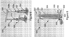
- a jack stand assembly 500 including a pair of jack stands 300 is shown in Figure 5 .
- Each jack stand includes a handle 502 fastened to the post 302.
- the jack stand assembly 500 includes two adjustable and extendable uprights 504 extending from the top of respective jack stands 300.
- a platform accessory 506 is supported by the uprights 504.
- Each upright 504 includes a pair of tubes 508a, 508b that can slide relative to each other to adjust the overall length.
- the assembly 500 further includes a screw fastener 510 for fastening the tubes 508a, 508b together at a fixed length.
- the assembly 500 further includes a bottom fastening arrangement 600 for fastening the tubular upright 504 to the base 400 of the stand 300.
- the fastening arrangement 600 includes a retainer 602 for inserting into the base 400 (see figure 7 ).
- the fastening arrangement 600 also includes a threaded screw fastener 604 for passing through the retainer 602 and engaging with a floor thread of the upright 504.
- the retainer 602 includes a plate from which one or more ledges extend into the base 400.
- the upright 504 includes a floor 606 defining the floor thread.
- the assembly 500 further includes a rotation inhibitor 608 for inhibiting rotation of the upright 504 in the stand 300.
- the inhibitor 608 includes a pin passing through the stand 300 and the upright 504.
- a collar 610 surrounds the upright 504 and forms a stop for abutting the jack top 106.
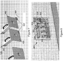
- Figure 8 shows a stand mounting bracket 800 for mounting the stand 300 along with a variety of accessories which can be used in conjunction with the stand 300.
- One accessory 506 includes a platform for supporting cables or hoses.
- Another accessory 802 includes one or more rollers for supporting metal strip material being fed to a cutting machine.
- Yet another accessory 804 includes a boat holder including a pair of angled rollers for holding the hull of a boat.
- Each accessory includes a bottom fastening receptacle 806 for fastening to the upright 504.
- the jack stand assembly 500 may similarly be formed using jack stands 100.
Landscapes
- Engineering & Computer Science (AREA)
- Mechanical Engineering (AREA)
- General Engineering & Computer Science (AREA)
- Life Sciences & Earth Sciences (AREA)
- Geology (AREA)
- Structural Engineering (AREA)
- Chemical & Material Sciences (AREA)
- Composite Materials (AREA)
- Moulding By Coating Moulds (AREA)
- Vehicle Cleaning, Maintenance, Repair, Refitting, And Outriggers (AREA)
- Jib Cranes (AREA)
Description
- The present invention relates to a light weight jack stand. The present invention has particular, although not excusive application to heavy-duty industrial jack stands for supporting vehicles, equipment, machinery and other like heavy loads (up to at least 30 tonne) in the earthmoving, trucking, mining and construction fields.
- The reference to any prior art in this specification is not, and should not be taken as an acknowledgement or any form of suggestion that the prior art forms part of the common general knowledge.
- Jack stands are commonly used to safely support heavy mining trucks that have been raised by a jack, or other means, for maintenance.
- Known jack stands are formed from metal parts such as steel to sustain the weight of the trucks. In turn, the jack stands themselves are very heavy which makes them cumbersome to move around. In practice, multiple persons are required to safely lift and position the jack stands in place which undesirably presents an injury risk. Alternatively, forklifts or loaders are used to lift and position the jack stands which is safer, but often less convenient, more expensive, slower and less productive.
- There is a need for a light weight jack stand that can be manually moved in a safe and convenient manner, but which can still safely support the required applied loads.
- Document
GB 1573877 - Document
WO 2008/147393 discloses a fiber reinforced core panel formed from strips of plastics foam helically wound with layers of rovings to form webs which may extend in a wave pattern or may intersect transverse webs. Hollow tubes may replace foam strips. Axial rovings cooperate with overlying helically wound rovings to form a beam or a column. Wound roving patterns may vary along strips for structural efficiency. Wound strips may alternate with spaced strips, and spacers between the strips enhance web buckling strength. Continuously wound rovings between spaced strips permit folding to form panels with reinforced edges. Continuously wound strips are helically wrapped to form annular structures, and composite panels may combine both thermoset and thermoplastic resins. Continuously wound strips or strip sections may be continuously fed either longitudinally or laterally into molding apparatus which may receive skin materials to form reinforced composite panels. - Document
US 5946880 discloses a one-piece unitary composite tubular support column. The tubular column includes relatively thin and strong sidewalls, capable of withstanding axial load distributions of at least 6,000 psi without failure of the composite. An embodiment includes a neck piece for mounting telescopically into an upper open end of the composite tubular support column. - According to one aspect of the present invention, there is provided a jack stand including:
- a base;
- a post including composite material formed via a pultrusion process and for extending from the base, the composite material including reinforcing fibres wound around the post to improve compressive strength, the reinforcing fibres being separately wound in both clock-wise and anticlockwise directions along the post to further improve compressive strength; and
- a top for topping the post and for engaging with a load.
- Advantageously, the post may be lightweight (typically less than 12kg) enabling the jack stand to be conveniently moved by a single person without exposing the person to significant risk of injury. The jack stand may be moved as a whole, or in parts.
- The composite material may include polymeric resin material and high strength fibres. The fibre material may include glass fibre, carbon fibre, and aramid fibre. The composite material may include a matting to align fibers in orientations other than longitudinally along the post to improve compressive strength. The post may be tubular. The post may be rated to up to at least 12 tonne. The post may have a single wall. The post may be rated up to 12 tonne. Alternatively, the post may have two or more walls. The post may be rated up to 30 tonne. The walls may be bonded together. The post may include a curved (e.g. circular) wall and a quadrilateral (e.g. square) wall.
- The base may be wider than the post to distribute weight of the load. The base may define a receptacle for receiving the post. The receptacle may include an outer wall and an inner wall of different shape and for forming a complementary fit with the post. The base may include a plate from which the receptacle extends. The base may further include one or more strengthening fillets extending between the receptacle and the plate.
- The top may define a receptacle for receiving the post. The top may define a cradle for cradling and contacting the load. The top may include a cap for capping the post.
- The base and/or top may include metal material, preferably steel or metal alloy.
- The jack stand may include a handle fastened to the post.
- According to another aspect of the present invention, there is provided a jack stand assembly including:
- at least one jack stand; and
- at least one upright extending from a respective jack stand; and
- an accessory supported by the upright.
- The upright may be adjustable. The upright may include a pair of tubes that can slide relative to each other. The assembly may include a fastener for fastening the tubes together.
- The upright may be received in a post of the jack stand. The assembly may include a fastening arrangement for fastening the upright to a base of the stand. The fastening arrangement may include a retainer for inserting into the base and a threaded fastener for passing through the retainer and engaging with a thread of the upright. The retainer may include a plate from which one or more ledges extend into the base. The upright may include a floor defining the thread.
- The assembly may include a rotation inhibitor for inhibiting rotation of the upright in the stand. The inhibitor may include a pin passing through the stand and the upright. The accessory may include a fastener for fastening to the upright.
- The accessory may include a platform for supporting cables or hoses. The accessory may include one or more rollers for supporting material being fed to a machine. The accessory may include a holder for holding a object. The holder may include a pair of angled rollers for holding the hull of a boat.
- According to another aspect of the present invention, there is provided a jack stand post including composite material formed via a pultrusion process, the composite material including reinforcing fibres wound around the post to improve compressive strength, the reinforcing fibres being separately wound in both clock-wise and anticlockwise directions along the post to further improve compressive strength.
- According to another aspect of the present invention, there is provided a method of manufacturing a jack stand, the method involving:
forming a post by pultruding with fibres and liquid polymeric resin material in a heated die to form composite material, the forming involving winding reinforcing fibres around the post to improve compressive strength, the reinforcing fibres being separately wound in both clock-wise and anticlockwise directions along the post to further improve compressive strength. - The step of forming may involve introducing a matting to align fibers of the composite material in orientations other than longitudinally along the post to improve compressive strength.
- Any of the features described herein can be combined in any combination with any one or more of the other features described herein within the scope of the invention.
- Preferred features, embodiments and variations of the invention may be discerned from the following Detailed Description which provides sufficient information for those skilled in the art to perform the invention. The Detailed Description is not to be regarded as limiting the scope of the preceding Summary of the Invention in any way. The Detailed Description will make reference to a number of drawings as follows:
-
Figure 1 is a perspective view of a 12 tonne jack stand in accordance with an embodiment of the present invention; -
Figure 2 is a sectional perspective view of the jack stand ofFigure 1 ; -
Figure 3 is a sectional perspective view of a 30 tonne jack stand in accordance with another embodiment of the present invention; -
Figure 4 is a perspective top view of a base of the jack stand ofFigure 3 ; -
Figure 5 is a perspective view of a jack stand assembly including the jack stand offigure 3 ; -
Figure 6 is a sectional perspective view of a portion of the jack stand assembly offigure 5 ; -
Figure 7 is a lower perspective view showing assembly of the jack stand assembly offigure 5 ; and -
Figure 8 is a perspective view of a jack stand and accessory mounting bracket. - According to an embodiment of the present invention, there is provided an industrial heavy-duty twelve-tonne (12t)
jack stand 100 as shown inFigure 1 . Thestand 100 includes abase 102 for resting on the ground. Apost 104 including composite material is provided and extends upwardly from thebase 102. The jack stand 100 further includes a top 106 for topping thepost 104 and for engaging with a vehicle (load). - Advantageously, the
post 104 is lightweight (typically less than 12kg) enabling the jack stand 100 to be conveniently moved by a single person without exposing the person to significant risk of injury. The jack stand 104 can be moved as a whole, or in parts. - Turning to
Figure 2 , thepost 104 has a square and tubularsingle wall 201, although is still comfortably rated to hold up to 12 tonne (with a safety factor of 3x). - The
base 102 is wider than thepost 104 to distribute weight of the vehicle and to provide stability relative to the height of the post. Furthermore, thebase 102 defines areceptacle 200, in the form of an endless square channel, for complementarily receiving a lower end of thepost 104. The base 102 also includes aflat plate 202 from which thereceptacle 200 extends. Strengtheningfillets 204 extend between thereceptacle 200 and theplate 204. - The top 106 also defines a
receptacle 206 for receiving the top end of thepost 104. In effect, the top 106 defines an annular cap for snugly capping thepost 104. In addition, the top 106 defines atopside cradle 208 for cradling an axle of the vehicle. The top 106 may also be of a flat section, for use on flat undersides of vehicles/machines or on their chassis rails. - The
base 102 and top 106 are cast from metal material, preferably steel or metal alloy. - The composite material of the
post 104 is pultruded, and includes polymeric resin material and fibres. The composite material also includes a matting to align fibers in orientations other than longitudinally along the post to improve compressive strength. The composite material further includes reinforcing fibres wound around the post to improve compressive strength. The reinforcing fibres can be separately wound in both clock-wise and anticlockwise directions along thepost 201 to further improve compressive strength. The foregoing construction provides alightweight jack stand 100 that is strong enough to sustain heavy-duty industrial loads. - A method of manufacturing the
jack stand 100, with thepost 104 including the light weight and strong composite material, is now briefly described. - The
post 104 is formed by pultruding fibres and polymeric material to form the composite material. Pultrusion is a continuous moulding process whereby reinforcing fibres are saturated with a liquid polymer resin and then carefully formed and pulled through a heated die to form a uniform composite part. The manufacturing of parts or components by pultrusion results in straight constant cross section parts of virtually any desired length. The liquid polymer resin can be added to the matrix of structural fibres either before or during forming in the heated die. - Conventional pultrusion processes usually utilise very long reinforcing fibres or braided strands. The reinforcing fibres may include glass fibre, carboin fibre or aramid fibre. The strands are unfurled from coiled rolls (often called rovings) and longitudinally drawn into the preforming, resin impregnation and stationary die system.
- Composite materials manufactured by the foregoing pultrusion process have exceptional strength to weight properties in resisting tensile loads but relatively poor strength to weight properties in resisting compressive loads. This is due to the exceptional tensile load bearing material properties of the reinforcing fibres contained within the composite structural matrix.
- The forming of the
post 104 involves introducing a woven reinforcing fibre matting in the structural fibre matrix of theresultant post 104 to align fibers of the composite material in orientations other than longitudinally along theelongate post 104 to improve compressive strength. The resulting product has an increased ability to resist compressive forces as compared to products that do not have any form of other than longitudinal fibre orientation, as these fibres are to a greater or lesser degree placed under some form of tensile load. The matting is introduced either within the body of the composite material and/or as a surfacing material, to bind and surround the matrix of structural fibres in the pultrusion process. The surfacing material contributes the structural ability of the product but more importantly ensures a smooth acceptable finish is achieved for the finished part. - The forming of the
post 104 further involves winding reinforcing fibres around the composite material to improve compressive strength. The additional reinforcing fibres are axially wound around the composite material along the longitudinal axis of thepost 104, and hence around the longitudinal fibres and the woven mat, which can significantly increase the ability of thepost 104 to resist compressive loads. - The reinforcing fibres may be separately wound in both clock-wise and anticlockwise directions along the
post 104 to further improve compressive strength. The windings are laced into the matrix to provide comprehensive tensile load capacity in multiple axes of load. - Winding of the reinforcing fibres into the pultruded fibre matrix can be undertaken with large rotating frames holding the coiled reinforcing fibre rovings. Each roving rotates at a desired rotational speed relative to the longitudinal pultrusion process flow rate, and rotates in the rotational direction to achieve desired axial windings and density of fibre construction. Successive rotating frames can be counter-rotating to achieve the differential orientation of the windings.
- Manufacturing pultruded composite products in such a manner exhibits a substantially improved capability to resist compressive loads when compared to conventionally manufactured products that are not manufactured in this manner. Such products can be of any form or shape, including round, square, rectangular or angular, and of differing dimensions.
- The manufacturing of pultruded composite products that can achieve an adequate level of compressive load resistance offers significant opportunities for industrial uses, given the product's inherent properties of light weight relative to its load bearing capacity. When compared to existing steel or metal allow products, the incorporation of pultruded composite products as the primary load bearing support element may offer significant advantages.
- According to another embodiment of the present invention, there is provided an industrial heavy-duty thirty-tonne (30t)
jack stand 300 as shown inFigure 3 . The light-weight jack stand 300 is of similar construction to the jack stand 100 ofFigure 1 . - However, the
upright post 302 has twowalls inner wall 304 and a square (i.e. quadrilateral)outer wall 306. Thewalls post 104 is lightweight (typically less than 15kg) enabling the jack stand 100 to still be conveniently moved by a single person. -
Figure 4 shows thebase 400 of thejack stand 300. Thebase 400 defines areceptacle 402 with a circularinner wall 404 and squareouter wall 406 to form a complementary fit with thepost 302. Thepost walls receptacle walls - A jack stand assembly 500 including a pair of jack stands 300 is shown in
Figure 5 . Each jack stand includes ahandle 502 fastened to thepost 302. Thejack stand assembly 500 includes two adjustable andextendable uprights 504 extending from the top of respective jack stands 300. Aplatform accessory 506 is supported by theuprights 504. - Each
upright 504 includes a pair oftubes assembly 500 further includes ascrew fastener 510 for fastening thetubes - As can best be seen in
figure 6 , theupright 504 is received in thepost 302 of thejack stand 300. Theassembly 500 further includes abottom fastening arrangement 600 for fastening thetubular upright 504 to thebase 400 of thestand 300. Thefastening arrangement 600 includes aretainer 602 for inserting into the base 400 (seefigure 7 ). Thefastening arrangement 600 also includes a threadedscrew fastener 604 for passing through theretainer 602 and engaging with a floor thread of theupright 504. Theretainer 602 includes a plate from which one or more ledges extend into thebase 400. The upright 504 includes a floor 606 defining the floor thread. - The
assembly 500 further includes arotation inhibitor 608 for inhibiting rotation of the upright 504 in thestand 300. Theinhibitor 608 includes a pin passing through thestand 300 and theupright 504. Acollar 610 surrounds theupright 504 and forms a stop for abutting thejack top 106. -
Figure 8 shows astand mounting bracket 800 for mounting thestand 300 along with a variety of accessories which can be used in conjunction with thestand 300. Oneaccessory 506 includes a platform for supporting cables or hoses. Anotheraccessory 802 includes one or more rollers for supporting metal strip material being fed to a cutting machine. Yet anotheraccessory 804 includes a boat holder including a pair of angled rollers for holding the hull of a boat. Each accessory includes abottom fastening receptacle 806 for fastening to theupright 504. - The jack stand assembly 500 may similarly be formed using jack stands 100.
- A person skilled in the art will appreciate that many embodiments and variations can be made without departing from the ambit of the present invention.
- In compliance with the statute, the invention has been described in language more or less specific to structural or methodical features. It is to be understood that the invention is not limited to specific features shown or described since the means herein described comprises preferred forms of putting the invention into effect.
- Reference throughout this specification to 'one embodiment' or 'an embodiment' means that a particular feature, structure, or characteristic described in connection with the embodiment is included in at least one embodiment of the present invention. Thus, the appearance of the phrases 'in one embodiment' or 'in an embodiment' in various places throughout this specification are not necessarily all referring to the same embodiment. Furthermore, the particular features, structures, or characteristics may be combined in any suitable manner in one or more combinations.
Claims (14)
- A jack stand (100) including:a base (400);a post (104) including composite material formed via a pultrusion process and for extending from the base (400), the composite material including reinforcing fibres wound around the post (104) to improve compressive strength, the reinforcing fibres being separately wound in both clock-wise and anticlockwise directions along the post (104) to further improve compressive strength; anda top (106) for topping the post (104) and for engaging with a load.
- A jack stand (100) as claimed in claim 1, wherein the post (104) is less than 12kg enabling the jack stand (100) to be conveniently moved by a single person without exposing the person to significant risk of injury; or optionally
wherein the jack stand (100) can be moved in parts. - A jack stand (100) as claimed in claim 1, wherein the composite material includes polymeric resin material and fibres; and optionally
wherein the fibres include any one or more of glass fibres, carbon fibres, and aramid fibres. - A jack stand (100) as claimed in claim 1, wherein the composite material includes a matting to align fibers in orientations other than longitudinally along the post (104) to improve compressive strength; or optionally
wherein the post (104) is tubular; or optionally
wherein the post (104) is rated up to at least 12 tonne or 30 tonne; or optionally
wherein the post (104) has a single wall or two or more walls that are bonded together. - A jack stand (100) as claimed in claim 1, wherein the post (104) includes a curved wall (304) and a quadrilateral wall (306); or optionally
wherein the base (400) is wider than the post (104) to distribute weight of the load; or optionally
wherein the base (400) defines a receptacle (402) for receiving the post (104). - A jack stand (100) as claimed in claim 5, wherein the receptacle (402) includes an outer wall (406) and an inner wall (404) of different shape and for forming a complementary fit with the post (104).
- A jack stand (100) as claimed in claim 6, wherein the base (400) includes a plate (204) from which the receptacle (402) extends; and optionally
wherein the base (400) further includes one or more strengthening fillets (204) extending between the receptacle (402) and the plate (204). - A jack stand (100) as claimed in claim 1, wherein the top (106) defines a receptacle for receiving the post (104); or optionally
wherein the top (106) defines a cradle (208) for cradling and contacting the load. - A jack stand (100) as claimed in claim 1, wherein the top (106) includes a cap for capping the post (104); or optionally
wherein the base (400) and/or top (106) include metal material, preferably steel or metal alloy; or optionally
further including a handle (502) fastened to the post (104). - A jack stand assembly (500) including:at least one jack stand (100) as claimed in claim 1;at least one upright (504) extending from a respective jack stand (100); andan accessory (506) supported by the upright (504).
- A jack stand assembly (500) as claimed in claim 10, wherein the upright (504) is length adjustable; or optionally
wherein the upright (504) is received in a post (104) of the jack stand (100); or optionally
further including a fastening arrangement (600) for fastening the upright (504) to a base (400) of the stand (100). - A jack stand assembly (500) as claimed in claim 10, including a rotation inhibitor (608) for inhibiting rotation of the upright (504) relative to the stand (100); or optionally
wherein the accessory (506) includes any one of a platform, rollers or a holder. - A method of manufacturing a jack stand (100), the method involving:
forming a post (104) by pultruding with fibres and liquid polymeric resin material in a heated die to form composite material, the forming involving winding reinforcing fibres around the post (104) to improve compressive strength, the reinforcing fibres being separately wound in both clock-wise and anticlockwise directions along the post (104) to further improve compressive strength. - A method as claimed in claim 13, wherein the step of forming involves introducing a matting to align fibers of the composite material in orientations other than longitudinally along the post (104) to improve compressive strength.
Applications Claiming Priority (2)
| Application Number | Priority Date | Filing Date | Title |
|---|---|---|---|
| AU2016901457A AU2016901457A0 (en) | 2016-04-19 | A light weight jack stand | |
| PCT/AU2017/050349 WO2017181229A1 (en) | 2016-04-19 | 2017-04-19 | A light weight jack stand |
Publications (3)
| Publication Number | Publication Date |
|---|---|
| EP3445531A1 EP3445531A1 (en) | 2019-02-27 |
| EP3445531A4 EP3445531A4 (en) | 2019-10-16 |
| EP3445531B1 true EP3445531B1 (en) | 2021-05-26 |
Family
ID=60115439
Family Applications (1)
| Application Number | Title | Priority Date | Filing Date |
|---|---|---|---|
| EP17785160.7A Active EP3445531B1 (en) | 2016-04-19 | 2017-04-19 | A light weight jack stand |
Country Status (8)
| Country | Link |
|---|---|
| US (1) | US11014792B2 (en) |
| EP (1) | EP3445531B1 (en) |
| JP (1) | JP2019513660A (en) |
| CN (1) | CN109070329A (en) |
| AU (1) | AU2017254731B2 (en) |
| CA (1) | CA3022762C (en) |
| WO (1) | WO2017181229A1 (en) |
| ZA (1) | ZA201807396B (en) |
Families Citing this family (9)
| Publication number | Priority date | Publication date | Assignee | Title |
|---|---|---|---|---|
| WO2017181229A1 (en) * | 2016-04-19 | 2017-10-26 | JP Composites Pty Ltd | A light weight jack stand |
| AU2019316498B2 (en) * | 2018-07-31 | 2025-05-08 | Stand Technologies Pty Ltd | A heavy-duty jack stand |
| AU2019229452A1 (en) * | 2018-09-06 | 2020-03-26 | Drill-Bourn Pty Ltd | Machine Stand and Method of Supporting a Machine using a Stand |
| USD901818S1 (en) * | 2018-12-14 | 2020-11-10 | Vis, Llc | Jack stand |
| USD937529S1 (en) * | 2020-08-19 | 2021-11-30 | Changyuan Lu | Adjustable stabilizer |
| USD1019047S1 (en) * | 2021-04-19 | 2024-03-19 | Pro Eagle LLC | Bottle jack |
| USD1028412S1 (en) * | 2022-07-15 | 2024-05-21 | Shenzhen Far-reaching Development Co., Ltd. | Support leg |
| USD1029445S1 (en) * | 2022-07-15 | 2024-05-28 | Shenzhen Far-reaching Development Co., Ltd. | Support leg |
| USD1110663S1 (en) * | 2023-10-11 | 2026-01-27 | Yihua Ou | Jack stabilizer |
Family Cites Families (43)
| Publication number | Priority date | Publication date | Assignee | Title |
|---|---|---|---|---|
| US964394A (en) * | 1909-10-11 | 1910-07-12 | Charles M Stuart | Lifting-jack. |
| US1171626A (en) * | 1915-04-26 | 1916-02-15 | Samuel E Moore | Jack. |
| US2723705A (en) | 1950-07-21 | 1955-11-15 | Owens Corning Fiberglass Corp | Method and apparatus for making reinforced plastic laminates |
| US4042202A (en) * | 1976-05-13 | 1977-08-16 | Molinari Delmo C | Jack stand with safety locking device |
| GB1573877A (en) * | 1977-03-24 | 1980-08-28 | Atomic Energy Of Australia | Formation of reinforced plastic tubing |
| US4245808A (en) * | 1979-05-21 | 1981-01-20 | Norco Industries, Inc. | Compact interlocking jack stand |
| US5048441A (en) * | 1989-06-15 | 1991-09-17 | Fiberspar, Inc. | Composite sail mast with high bending strength |
| US5085406A (en) * | 1990-12-05 | 1992-02-04 | Ausco Products, Inc. | Thumb wheel for a jack |
| US5180131A (en) * | 1991-07-25 | 1993-01-19 | Norco Industries, Inc | Spring loaded jack stand |
| US5692351A (en) | 1995-03-20 | 1997-12-02 | William S. Morrison, III | Column support system with neck piece for supporting overhead loads |
| US5575591A (en) * | 1995-04-24 | 1996-11-19 | Vanderklaauw; Peter M. | Apparatus and method for a modular support and lifting system |
| US5611514A (en) * | 1995-07-13 | 1997-03-18 | Oliver; James | Adjustable pipe pier |
| US5664762A (en) * | 1996-09-11 | 1997-09-09 | Ausco Products, Inc. | Automotive screw jack |
| JPH1118235A (en) * | 1997-06-27 | 1999-01-22 | Asahi Glass Matex Kk | Built-up type scaffolding |
| US6189285B1 (en) * | 1998-10-19 | 2001-02-20 | The Marley Cooling Tower Company | Pultruded FRP structural assembly for water cooling towers |
| JP2003012280A (en) * | 2001-07-02 | 2003-01-15 | Riken Seiko Kk | In-car jack |
| TW532445U (en) * | 2001-08-01 | 2003-05-11 | Shin-Tsai Huang | Locking mechanism for adjustment structure of bar component |
| US7487576B2 (en) | 2003-02-03 | 2009-02-10 | Husqvarna Outdoor Products Inc. | Composite track, column and other supports, including for machinery |
| US7214007B2 (en) * | 2003-02-03 | 2007-05-08 | Husqvarna Outdoor Products Inc. | Composite track, column and other supports, including for machinery |
| USD513819S1 (en) * | 2003-12-09 | 2006-01-24 | K.K.U. Incorporated | Jack stand |
| US20050211868A1 (en) * | 2004-02-13 | 2005-09-29 | Jason Scott | Support system and method |
| CN101238059A (en) * | 2005-04-28 | 2008-08-06 | 伍德利投资有限公司 | jack |
| US8201807B2 (en) * | 2005-11-23 | 2012-06-19 | Alltrade Tools Llc | Jack stand and combination and method of elevating a load |
| CN101646548B (en) * | 2006-11-09 | 2013-12-04 | 美利肯公司 | Fiber reinforced composite cores and panels |
| CA2621532C (en) * | 2007-02-15 | 2014-09-30 | Alltrade Tools Llc | Jack stand and jack combination and method of elevating a load |
| US20090179122A1 (en) * | 2007-11-30 | 2009-07-16 | James Inzero | Modular boat support |
| JP2011037001A (en) * | 2007-12-14 | 2011-02-24 | Nippon Zeon Co Ltd | Frp pipe |
| CN102066232B (en) * | 2008-02-11 | 2014-09-10 | 塞贝尔设计集团有限公司 | Ratcheting jack stand |
| US20090283653A1 (en) * | 2008-05-16 | 2009-11-19 | Larin Corporation | Jack stand and method for forming same |
| WO2010096935A1 (en) * | 2009-02-27 | 2010-09-02 | Flexpipe Systems Inc. | High temperature fiber reinforced pipe |
| JP2013541443A (en) * | 2010-09-17 | 2013-11-14 | スリーエム イノベイティブ プロパティズ カンパニー | Fiber reinforced nanoparticle loaded thermoset polymer composite wires and cables and methods |
| DE102012108132B4 (en) * | 2012-08-31 | 2015-01-22 | Firep Rebar Technology Gmbh | Process for the production of reinforcing elements made of fiber-reinforced plastic |
| US9080722B2 (en) * | 2012-11-23 | 2015-07-14 | Frank Carmel Ceravolo | Adjustable weight supporting apparatus and method |
| US9239126B2 (en) * | 2012-11-29 | 2016-01-19 | Bosch Automotive Service Solutions Inc. | Twist jack stand apparatus and method |
| DE102013001442B3 (en) * | 2013-01-29 | 2014-03-13 | Thyssenkrupp Presta Aktiengesellschaft | Steering column in fiber composite technology, based on pultrusion and braiding and / or winding technology |
| WO2015033135A1 (en) * | 2013-09-05 | 2015-03-12 | Oxford Plastic Systems Limited | Supporting temporary barriers |
| US9446743B2 (en) * | 2013-10-24 | 2016-09-20 | Kent R. Madison | Trailer jack support |
| USD746533S1 (en) * | 2014-04-28 | 2015-12-29 | Victor Hung | Jack stand |
| CN104626447A (en) * | 2014-12-02 | 2015-05-20 | 荣成复合材料有限公司 | Manufacturing method of composite material lifting jack |
| WO2017181229A1 (en) * | 2016-04-19 | 2017-10-26 | JP Composites Pty Ltd | A light weight jack stand |
| US20170349416A1 (en) * | 2016-06-01 | 2017-12-07 | Louis Joseph Sigouin | Jack Stand with Dual Column Support |
| WO2018160938A1 (en) * | 2017-03-02 | 2018-09-07 | B & B Steel Products | Jack mechanism with improved safety features |
| US10378680B2 (en) * | 2017-05-31 | 2019-08-13 | Erico International Corporation | Telescoping pipe stand |
-
2017
- 2017-04-19 WO PCT/AU2017/050349 patent/WO2017181229A1/en not_active Ceased
- 2017-04-19 US US16/094,010 patent/US11014792B2/en active Active
- 2017-04-19 CN CN201780024883.1A patent/CN109070329A/en active Pending
- 2017-04-19 JP JP2018555636A patent/JP2019513660A/en active Pending
- 2017-04-19 AU AU2017254731A patent/AU2017254731B2/en active Active
- 2017-04-19 EP EP17785160.7A patent/EP3445531B1/en active Active
- 2017-04-19 CA CA3022762A patent/CA3022762C/en active Active
-
2018
- 2018-11-05 ZA ZA2018/07396A patent/ZA201807396B/en unknown
Also Published As
| Publication number | Publication date |
|---|---|
| WO2017181229A1 (en) | 2017-10-26 |
| EP3445531A1 (en) | 2019-02-27 |
| CN109070329A (en) | 2018-12-21 |
| CA3022762C (en) | 2025-05-06 |
| CA3022762A1 (en) | 2017-10-26 |
| JP2019513660A (en) | 2019-05-30 |
| AU2017254731A1 (en) | 2018-11-08 |
| US20190127192A1 (en) | 2019-05-02 |
| EP3445531A4 (en) | 2019-10-16 |
| US11014792B2 (en) | 2021-05-25 |
| AU2017254731B2 (en) | 2020-07-02 |
| ZA201807396B (en) | 2019-09-25 |
Similar Documents
| Publication | Publication Date | Title |
|---|---|---|
| AU2017254731B2 (en) | A light weight jack stand | |
| EP1170117A1 (en) | Frp cylindrical body and production method thereof | |
| AU2025200207A1 (en) | A heavy-duty jack stand | |
| EP3062994B1 (en) | Continuous production of profiles in a sandwich structure with foam cores and profile with hard-foam core | |
| EP2951077B1 (en) | Steering column produced from fibre-composite and on the basis of pultrusion, braiding and/or winding technology | |
| WO2016044669A1 (en) | Hollow, composite rebar structure, associated fabrication methodolgy, and apparatus | |
| JP2009545466A (en) | Method of forming a plurality of fiber composite components | |
| DE3038820A1 (en) | STEERING WHEEL FOR A MOTOR VEHICLE AND METHOD FOR THE PRODUCTION THEREOF | |
| US9168701B2 (en) | Fiberglass reinforced plastic lightweight heavy-duty ladder and method of making same | |
| AU2021204617A1 (en) | Composite Rung for a Ladder and Method | |
| EP3883877B1 (en) | Cable drum for a cable winch and method for production thereof | |
| EP0018539A1 (en) | Fibre-web reinforced pneumatic tyres and process for their manufacture | |
| WO2024178470A1 (en) | Industrial hydraulic actuator safety device | |
| CN205876170U (en) | Combined material ladder | |
| JPS6148327B2 (en) | ||
| JPH0834065A (en) | FRP hollow body pultrusion method | |
| KR102300682B1 (en) | Lashing bar having composite materials, and manufacturing method for the same | |
| US3442296A (en) | Filament wound element | |
| CN106050123A (en) | Composite material ladder | |
| JPH0834066A (en) | Continuous pultrusion equipment | |
| AT518212B1 (en) | Mast, especially sailboat mast | |
| WO2021037389A1 (en) | Fiber-reinforced braided structural component having a plastic matrix, and method for producing said structural component | |
| WO2007001812A2 (en) | Composite dunnage bar system | |
| JPH07195539A (en) | Mandrel |
Legal Events
| Date | Code | Title | Description |
|---|---|---|---|
| STAA | Information on the status of an ep patent application or granted ep patent |
Free format text: STATUS: THE INTERNATIONAL PUBLICATION HAS BEEN MADE |
|
| PUAI | Public reference made under article 153(3) epc to a published international application that has entered the european phase |
Free format text: ORIGINAL CODE: 0009012 |
|
| STAA | Information on the status of an ep patent application or granted ep patent |
Free format text: STATUS: REQUEST FOR EXAMINATION WAS MADE |
|
| 17P | Request for examination filed |
Effective date: 20181016 |
|
| AK | Designated contracting states |
Kind code of ref document: A1 Designated state(s): AL AT BE BG CH CY CZ DE DK EE ES FI FR GB GR HR HU IE IS IT LI LT LU LV MC MK MT NL NO PL PT RO RS SE SI SK SM TR |
|
| AX | Request for extension of the european patent |
Extension state: BA ME |
|
| RAP1 | Party data changed (applicant data changed or rights of an application transferred) |
Owner name: STAND TECHNOLOGIES PTY LTD |
|
| DAV | Request for validation of the european patent (deleted) | ||
| DAX | Request for extension of the european patent (deleted) | ||
| A4 | Supplementary search report drawn up and despatched |
Effective date: 20190918 |
|
| RIC1 | Information provided on ipc code assigned before grant |
Ipc: B66F 3/00 20060101ALI20190912BHEP Ipc: F16M 11/00 20060101ALI20190912BHEP Ipc: F16M 11/22 20060101ALI20190912BHEP Ipc: B25H 1/00 20060101AFI20190912BHEP Ipc: B29C 70/52 20060101ALI20190912BHEP Ipc: F16M 11/26 20060101ALI20190912BHEP |
|
| RIC1 | Information provided on ipc code assigned before grant |
Ipc: B29C 70/52 20060101ALI20201221BHEP Ipc: B29L 31/06 20060101ALI20201221BHEP Ipc: F16M 11/00 20060101ALI20201221BHEP Ipc: B66F 3/00 20060101ALI20201221BHEP Ipc: B29C 70/32 20060101ALI20201221BHEP Ipc: F16M 11/22 20060101ALI20201221BHEP Ipc: F16M 11/26 20060101ALI20201221BHEP Ipc: B25H 1/00 20060101AFI20201221BHEP |
|
| GRAP | Despatch of communication of intention to grant a patent |
Free format text: ORIGINAL CODE: EPIDOSNIGR1 |
|
| STAA | Information on the status of an ep patent application or granted ep patent |
Free format text: STATUS: GRANT OF PATENT IS INTENDED |
|
| INTG | Intention to grant announced |
Effective date: 20210203 |
|
| GRAS | Grant fee paid |
Free format text: ORIGINAL CODE: EPIDOSNIGR3 |
|
| GRAA | (expected) grant |
Free format text: ORIGINAL CODE: 0009210 |
|
| STAA | Information on the status of an ep patent application or granted ep patent |
Free format text: STATUS: THE PATENT HAS BEEN GRANTED |
|
| AK | Designated contracting states |
Kind code of ref document: B1 Designated state(s): AL AT BE BG CH CY CZ DE DK EE ES FI FR GB GR HR HU IE IS IT LI LT LU LV MC MK MT NL NO PL PT RO RS SE SI SK SM TR |
|
| REG | Reference to a national code |
Ref country code: GB Ref legal event code: FG4D |
|
| REG | Reference to a national code |
Ref country code: CH Ref legal event code: EP |
|
| REG | Reference to a national code |
Ref country code: DE Ref legal event code: R096 Ref document number: 602017039334 Country of ref document: DE |
|
| REG | Reference to a national code |
Ref country code: AT Ref legal event code: REF Ref document number: 1395741 Country of ref document: AT Kind code of ref document: T Effective date: 20210615 |
|
| REG | Reference to a national code |
Ref country code: IE Ref legal event code: FG4D |
|
| REG | Reference to a national code |
Ref country code: LT Ref legal event code: MG9D |
|
| REG | Reference to a national code |
Ref country code: AT Ref legal event code: MK05 Ref document number: 1395741 Country of ref document: AT Kind code of ref document: T Effective date: 20210526 |
|
| PG25 | Lapsed in a contracting state [announced via postgrant information from national office to epo] |
Ref country code: AT Free format text: LAPSE BECAUSE OF FAILURE TO SUBMIT A TRANSLATION OF THE DESCRIPTION OR TO PAY THE FEE WITHIN THE PRESCRIBED TIME-LIMIT Effective date: 20210526 Ref country code: BG Free format text: LAPSE BECAUSE OF FAILURE TO SUBMIT A TRANSLATION OF THE DESCRIPTION OR TO PAY THE FEE WITHIN THE PRESCRIBED TIME-LIMIT Effective date: 20210826 Ref country code: HR Free format text: LAPSE BECAUSE OF FAILURE TO SUBMIT A TRANSLATION OF THE DESCRIPTION OR TO PAY THE FEE WITHIN THE PRESCRIBED TIME-LIMIT Effective date: 20210526 Ref country code: FI Free format text: LAPSE BECAUSE OF FAILURE TO SUBMIT A TRANSLATION OF THE DESCRIPTION OR TO PAY THE FEE WITHIN THE PRESCRIBED TIME-LIMIT Effective date: 20210526 Ref country code: LT Free format text: LAPSE BECAUSE OF FAILURE TO SUBMIT A TRANSLATION OF THE DESCRIPTION OR TO PAY THE FEE WITHIN THE PRESCRIBED TIME-LIMIT Effective date: 20210526 |
|
| REG | Reference to a national code |
Ref country code: NL Ref legal event code: MP Effective date: 20210526 |
|
| PG25 | Lapsed in a contracting state [announced via postgrant information from national office to epo] |
Ref country code: RS Free format text: LAPSE BECAUSE OF FAILURE TO SUBMIT A TRANSLATION OF THE DESCRIPTION OR TO PAY THE FEE WITHIN THE PRESCRIBED TIME-LIMIT Effective date: 20210526 Ref country code: SE Free format text: LAPSE BECAUSE OF FAILURE TO SUBMIT A TRANSLATION OF THE DESCRIPTION OR TO PAY THE FEE WITHIN THE PRESCRIBED TIME-LIMIT Effective date: 20210526 Ref country code: NO Free format text: LAPSE BECAUSE OF FAILURE TO SUBMIT A TRANSLATION OF THE DESCRIPTION OR TO PAY THE FEE WITHIN THE PRESCRIBED TIME-LIMIT Effective date: 20210826 Ref country code: PT Free format text: LAPSE BECAUSE OF FAILURE TO SUBMIT A TRANSLATION OF THE DESCRIPTION OR TO PAY THE FEE WITHIN THE PRESCRIBED TIME-LIMIT Effective date: 20210927 Ref country code: PL Free format text: LAPSE BECAUSE OF FAILURE TO SUBMIT A TRANSLATION OF THE DESCRIPTION OR TO PAY THE FEE WITHIN THE PRESCRIBED TIME-LIMIT Effective date: 20210526 Ref country code: LV Free format text: LAPSE BECAUSE OF FAILURE TO SUBMIT A TRANSLATION OF THE DESCRIPTION OR TO PAY THE FEE WITHIN THE PRESCRIBED TIME-LIMIT Effective date: 20210526 Ref country code: IS Free format text: LAPSE BECAUSE OF FAILURE TO SUBMIT A TRANSLATION OF THE DESCRIPTION OR TO PAY THE FEE WITHIN THE PRESCRIBED TIME-LIMIT Effective date: 20210926 Ref country code: GR Free format text: LAPSE BECAUSE OF FAILURE TO SUBMIT A TRANSLATION OF THE DESCRIPTION OR TO PAY THE FEE WITHIN THE PRESCRIBED TIME-LIMIT Effective date: 20210827 |
|
| PG25 | Lapsed in a contracting state [announced via postgrant information from national office to epo] |
Ref country code: NL Free format text: LAPSE BECAUSE OF FAILURE TO SUBMIT A TRANSLATION OF THE DESCRIPTION OR TO PAY THE FEE WITHIN THE PRESCRIBED TIME-LIMIT Effective date: 20210526 |
|
| PG25 | Lapsed in a contracting state [announced via postgrant information from national office to epo] |
Ref country code: SK Free format text: LAPSE BECAUSE OF FAILURE TO SUBMIT A TRANSLATION OF THE DESCRIPTION OR TO PAY THE FEE WITHIN THE PRESCRIBED TIME-LIMIT Effective date: 20210526 Ref country code: SM Free format text: LAPSE BECAUSE OF FAILURE TO SUBMIT A TRANSLATION OF THE DESCRIPTION OR TO PAY THE FEE WITHIN THE PRESCRIBED TIME-LIMIT Effective date: 20210526 Ref country code: ES Free format text: LAPSE BECAUSE OF FAILURE TO SUBMIT A TRANSLATION OF THE DESCRIPTION OR TO PAY THE FEE WITHIN THE PRESCRIBED TIME-LIMIT Effective date: 20210526 Ref country code: RO Free format text: LAPSE BECAUSE OF FAILURE TO SUBMIT A TRANSLATION OF THE DESCRIPTION OR TO PAY THE FEE WITHIN THE PRESCRIBED TIME-LIMIT Effective date: 20210526 Ref country code: DK Free format text: LAPSE BECAUSE OF FAILURE TO SUBMIT A TRANSLATION OF THE DESCRIPTION OR TO PAY THE FEE WITHIN THE PRESCRIBED TIME-LIMIT Effective date: 20210526 Ref country code: CZ Free format text: LAPSE BECAUSE OF FAILURE TO SUBMIT A TRANSLATION OF THE DESCRIPTION OR TO PAY THE FEE WITHIN THE PRESCRIBED TIME-LIMIT Effective date: 20210526 Ref country code: EE Free format text: LAPSE BECAUSE OF FAILURE TO SUBMIT A TRANSLATION OF THE DESCRIPTION OR TO PAY THE FEE WITHIN THE PRESCRIBED TIME-LIMIT Effective date: 20210526 |
|
| REG | Reference to a national code |
Ref country code: DE Ref legal event code: R097 Ref document number: 602017039334 Country of ref document: DE |
|
| PLBE | No opposition filed within time limit |
Free format text: ORIGINAL CODE: 0009261 |
|
| STAA | Information on the status of an ep patent application or granted ep patent |
Free format text: STATUS: NO OPPOSITION FILED WITHIN TIME LIMIT |
|
| 26N | No opposition filed |
Effective date: 20220301 |
|
| PG25 | Lapsed in a contracting state [announced via postgrant information from national office to epo] |
Ref country code: IS Free format text: LAPSE BECAUSE OF FAILURE TO SUBMIT A TRANSLATION OF THE DESCRIPTION OR TO PAY THE FEE WITHIN THE PRESCRIBED TIME-LIMIT Effective date: 20210926 Ref country code: AL Free format text: LAPSE BECAUSE OF FAILURE TO SUBMIT A TRANSLATION OF THE DESCRIPTION OR TO PAY THE FEE WITHIN THE PRESCRIBED TIME-LIMIT Effective date: 20210526 |
|
| PG25 | Lapsed in a contracting state [announced via postgrant information from national office to epo] |
Ref country code: IT Free format text: LAPSE BECAUSE OF FAILURE TO SUBMIT A TRANSLATION OF THE DESCRIPTION OR TO PAY THE FEE WITHIN THE PRESCRIBED TIME-LIMIT Effective date: 20210526 |
|
| REG | Reference to a national code |
Ref country code: CH Ref legal event code: PL |
|
| REG | Reference to a national code |
Ref country code: BE Ref legal event code: MM Effective date: 20220430 |
|
| PG25 | Lapsed in a contracting state [announced via postgrant information from national office to epo] |
Ref country code: MC Free format text: LAPSE BECAUSE OF FAILURE TO SUBMIT A TRANSLATION OF THE DESCRIPTION OR TO PAY THE FEE WITHIN THE PRESCRIBED TIME-LIMIT Effective date: 20210526 Ref country code: LU Free format text: LAPSE BECAUSE OF NON-PAYMENT OF DUE FEES Effective date: 20220419 Ref country code: LI Free format text: LAPSE BECAUSE OF NON-PAYMENT OF DUE FEES Effective date: 20220430 Ref country code: CH Free format text: LAPSE BECAUSE OF NON-PAYMENT OF DUE FEES Effective date: 20220430 |
|
| PG25 | Lapsed in a contracting state [announced via postgrant information from national office to epo] |
Ref country code: BE Free format text: LAPSE BECAUSE OF NON-PAYMENT OF DUE FEES Effective date: 20220430 |
|
| PG25 | Lapsed in a contracting state [announced via postgrant information from national office to epo] |
Ref country code: IE Free format text: LAPSE BECAUSE OF NON-PAYMENT OF DUE FEES Effective date: 20220419 |
|
| P01 | Opt-out of the competence of the unified patent court (upc) registered |
Effective date: 20230512 |
|
| P04 | Withdrawal of opt-out of the competence of the unified patent court (upc) registered |
Effective date: 20230522 |
|
| PG25 | Lapsed in a contracting state [announced via postgrant information from national office to epo] |
Ref country code: HU Free format text: LAPSE BECAUSE OF FAILURE TO SUBMIT A TRANSLATION OF THE DESCRIPTION OR TO PAY THE FEE WITHIN THE PRESCRIBED TIME-LIMIT; INVALID AB INITIO Effective date: 20170419 |
|
| PG25 | Lapsed in a contracting state [announced via postgrant information from national office to epo] |
Ref country code: MK Free format text: LAPSE BECAUSE OF FAILURE TO SUBMIT A TRANSLATION OF THE DESCRIPTION OR TO PAY THE FEE WITHIN THE PRESCRIBED TIME-LIMIT Effective date: 20210526 Ref country code: CY Free format text: LAPSE BECAUSE OF FAILURE TO SUBMIT A TRANSLATION OF THE DESCRIPTION OR TO PAY THE FEE WITHIN THE PRESCRIBED TIME-LIMIT Effective date: 20210526 |
|
| PG25 | Lapsed in a contracting state [announced via postgrant information from national office to epo] |
Ref country code: MT Free format text: LAPSE BECAUSE OF FAILURE TO SUBMIT A TRANSLATION OF THE DESCRIPTION OR TO PAY THE FEE WITHIN THE PRESCRIBED TIME-LIMIT Effective date: 20210526 |
|
| PGFP | Annual fee paid to national office [announced via postgrant information from national office to epo] |
Ref country code: DE Payment date: 20250325 Year of fee payment: 9 |
|
| PG25 | Lapsed in a contracting state [announced via postgrant information from national office to epo] |
Ref country code: TR Free format text: LAPSE BECAUSE OF FAILURE TO SUBMIT A TRANSLATION OF THE DESCRIPTION OR TO PAY THE FEE WITHIN THE PRESCRIBED TIME-LIMIT Effective date: 20210526 |
|
| PGFP | Annual fee paid to national office [announced via postgrant information from national office to epo] |
Ref country code: GB Payment date: 20260325 Year of fee payment: 10 |
|
| PGFP | Annual fee paid to national office [announced via postgrant information from national office to epo] |
Ref country code: FR Payment date: 20260323 Year of fee payment: 10 |