EP3444941A1 - Shorted rotating diode protection for synchronous machines - Google Patents
Shorted rotating diode protection for synchronous machines Download PDFInfo
- Publication number
- EP3444941A1 EP3444941A1 EP18188550.0A EP18188550A EP3444941A1 EP 3444941 A1 EP3444941 A1 EP 3444941A1 EP 18188550 A EP18188550 A EP 18188550A EP 3444941 A1 EP3444941 A1 EP 3444941A1
- Authority
- EP
- European Patent Office
- Prior art keywords
- gate
- exciter
- diode
- winding
- exciter winding
- Prior art date
- Legal status (The legal status is an assumption and is not a legal conclusion. Google has not performed a legal analysis and makes no representation as to the accuracy of the status listed.)
- Granted
Links
Images




Classifications
-
- H—ELECTRICITY
- H02—GENERATION; CONVERSION OR DISTRIBUTION OF ELECTRIC POWER
- H02P—CONTROL OR REGULATION OF ELECTRIC MOTORS, ELECTRIC GENERATORS OR DYNAMO-ELECTRIC CONVERTERS; CONTROLLING TRANSFORMERS, REACTORS OR CHOKE COILS
- H02P9/00—Arrangements for controlling electric generators for the purpose of obtaining a desired output
- H02P9/006—Means for protecting the generator by using control
-
- H—ELECTRICITY
- H02—GENERATION; CONVERSION OR DISTRIBUTION OF ELECTRIC POWER
- H02P—CONTROL OR REGULATION OF ELECTRIC MOTORS, ELECTRIC GENERATORS OR DYNAMO-ELECTRIC CONVERTERS; CONTROLLING TRANSFORMERS, REACTORS OR CHOKE COILS
- H02P9/00—Arrangements for controlling electric generators for the purpose of obtaining a desired output
- H02P9/14—Arrangements for controlling electric generators for the purpose of obtaining a desired output by variation of field
- H02P9/26—Arrangements for controlling electric generators for the purpose of obtaining a desired output by variation of field using discharge tubes or semiconductor devices
- H02P9/30—Arrangements for controlling electric generators for the purpose of obtaining a desired output by variation of field using discharge tubes or semiconductor devices using semiconductor devices
- H02P9/302—Brushless excitation
Definitions
- This disclosure relates generally to synchronous machines, and more specifically to protection or isolation of circuitry during operation.
- Synchronous machines are known. Synchronous machines include a stationary portion and a rotating portion, where the rotating portion and the stationary portion each have at least one winding.
- One application of synchronous machines is a generator arrangement for gas turbine engines to power the various components of the engine and/or aircraft.
- the synchronous machine includes a field winding on the rotating portion and an armature winding on the stationary portion.
- Current supplied to the field winding generates a magnetic field between the rotating portion and the stationary portion, causing current to be generated at the armature winding.
- the rotating portion typically includes one or more rotating diodes to rectify current to the field winding.
- one of the rotating diodes may become shorted or otherwise malfunction, sometimes referred to as a "shorted rotating diode" (SRD).
- SRD shorted rotating diode
- one or more portions of the stationary portion are electrically isolated from the SRD during an SRD event.
- An assembly engine includes a synchronous machine including a rotating portion and a stationary portion, the rotating portion including at least one rotating diode coupled to a field winding, and the stationary portion including a stator winding and an exciter winding, and a control unit including a first gate and a second gate.
- the exciter winding is connected in series to the first gate and the second gate during a first operating mode to energize the exciter winding.
- the exciter winding is electrically connected in series to a first gate but is electrically disconnected from the second gate in a second, different operating mode to electrically disconnect the exciter winding from an exciter energy source.
- a synchronous machine and a method of operating a synchronous machine are also disclosed.
- the disclosed embodiments of a synchronous machine include a rotating rectifier protection circuit that is operable to electrically isolate components of the synchronous machine in response to an SRD event that may occur due to a faulty rotating diode.
- FIG. 1 illustrates a synchronous machine 20 that may be utilized to generate power.
- the synchronous machine 20 includes a rotating portion 22 and a stationary portion 24 that is arranged at least partially about the rotating portion 22 to define an air gap.
- the rotating portion 22 includes a rotating rectifier 26 having one or more rotating diodes 28 (three pairs of diodes shown) coupled between one or more main rotor windings 30 and a rotating field winding 32.
- a supply of current from the main rotor windings 30 is communicated to the rotating rectifier 26 to convert AC current to DC current, for example, which is supplied to the rotating field winding 32.
- the stationary portion 24 includes an exciter energy source such as a permanent magnet generator (PMG) 34.
- the exciter energy source is a flux switching generator.
- the stationary portion 24 also includes an exciter winding 36 and one or more main stator windings 38.
- main rotor windings 30, PMG 34 and stator windings 38 are depicted as having three-phase windings, fewer or more than three phases can be utilized with the teachings herein, such as single-phase or two-phase arrangements.
- exciter winding 36 is depicted as having a single winding, more than one winding can be utilized, such as an exciter having three-phase windings.
- PMG 34 is depicted as a full-wave arrangement (i.e., no neutral). In other examples, the PMG 34 comprises a half-wave arrangement (i.e., phases A, B, C and neutral). The PMG 34 may be a portion of another synchronous machine, and supplies an amount of current to the exciter winding 36.
- a rotating magnetic field is generated by supplying current to the rotating field winding 32 which generates a rotating magnetic field to induce current in the main stator windings 38 in response to relative rotation of the rotating and stationary portions 22, 24.
- the induced current may be supplied to one or more loads L (one shown in dashed lines for illustrative purposes).
- Example loads L can include engine controls, actuators and auxiliary systems of an aircraft.
- the synchronous machine 20 includes a generator control relay or unit 40 provided with a rotating rectifier protection circuit.
- the control unit 40 is operable to control exciter winding 36 to selectively induce a current in, or otherwise energize, main rotor windings 30 in order to generate a magnetic field between rotating field winding 32 and stator windings 38.
- the control unit 40 has a first set of inputs 42 relating to each of three phases A-C and neutral N carried on output terminals 39 of the main stator windings 38, a second set of inputs 44 for windings of the PMG 34.
- the inputs 44 are coupled to one or more output terminals 45 of the PMG 34 via phase lines 47.
- FIG. 2A illustrates details of an exemplary control unit 140.
- like reference numerals designate like elements where appropriate and reference numerals with the addition of one-hundred or multiples thereof designate modified elements that are understood to incorporate the same features and benefits of the corresponding original elements.
- the control unit 140 includes a bridge rectifier 146.
- the rectifier 146 can include one or more pairs of diodes 148 coupled to respective output terminals 145 of the PMG 134 via phase lines 147.
- the PMG 134 supplies voltage to the rectifier 146, which rectifies AC current carried on phase lines 147 to DC current.
- the rectifier 146 communicates the DC current to exciter winding 136.
- the PMG 134 is a three-phase generator with phase lines 147 each coupled to respective pairs of diodes 148 of the rectifier 146.
- control unit 240 is arranged with rectifier 246 including three diodes 248, with phase lines 247 coupling phases A, B, C to respective diodes 248, and a neutral line N of PMG 234 connected to ground.
- the rectifier 146 is arranged in parallel with a capacitor 150.
- the exciter winding 136 is connected in parallel with the rectifier 146 and with the capacitor 150.
- the rectifier 146 can be arranged in parallel with a transient-voltage-suppression (TVS) diode 152 (connections shown in dashed lines), sometimes referred to as a "transorb.”
- TVS diodes can be utilized to "clamp" or otherwise maintain voltage within a desired range or value.
- the capacitor 150 and TVS diode 152 can be utilized to protect or isolate circuitry of the control unit 140 during an SRD event, as discussed in more detail below.
- the circuitry of the control unit 140 including between PMG 134 and exciter winding 136, is free of any TVS diodes. Omission of TVS diodes can reduce system complexity, size, and cost, for example.
- the control unit 140 includes a first switch or gate 154 and a second switch or gate 156.
- the control unit 140 also includes a first diode 158 and a second diode 160.
- the first gate 154 and the second gate 156 are NMOS transistors.
- Other transistors, including other types of field-effect transistors (FET) and bipolar junction transistors, and other types of switch logic may also be utilized.
- the control unit 140 is arranged to define a plurality of nodes.
- the nodes include at least a first node N1, a second node N2, a third node N3, and a fourth node N4.
- components of the first node N1 comprise the rectifier 146, the capacitor 150, the TVS diode 152, a drain terminal of the first gate 154, and a cathode of the second diode 160.
- the circuitry of the control unit 140 is free of any TVS diodes such that the first node N1 consists of the rectifier 146, the capacitor 150, the drain terminal of the first gate 154, and the cathode of the second diode 160.
- Components of the second node N2 comprise a first terminal 136A of the exciter winding 136, a cathode of the first diode 158, and a source terminal of the first gate 154.
- Components of the third node N3 comprise a second terminal 136B of the exciter winding 136, an anode of the second diode 160, and a drain terminal of the second transistor or gate 156.
- Components of the fourth node N4 include the rectifier 146, the capacitor 150, a source terminal of the second gate 156, and an anode of the first diode 158.
- node N4 is coupled to ground (shown schematically). In other examples, the ground (shown schematically) at node N4 is omitted.
- the control unit 140 includes a gate drive 162 that is operable to independently control each of the first and second gates 154, 156.
- the gate drive 162 includes a first drive module 162A and a second drive module 162B.
- the first drive module 162A is electrically coupled to the first gate 154 via a first gate drive signal line 164A
- the second drive module 162B is electrically coupled to the second gate 156 via a second gate drive signal line 164B.
- the gate drive 162 is programmed with control logic to independently modulate each of the first and second gates 154, 156.
- a gate drive communicated a single signal to two gates such that the gates operated together in the same opened and closed states.
- the gate drive 162 can include a processor and memory, for example.
- the processor may, for example only, be any type of known microprocessor having desired performance characteristics.
- the memory may, for example only, includes UVPROM, EEPROM, FLASH, RAM, ROM, DVD, CD, a hard drive, or other computer readable medium which may store data for operation of the control unit 140 as described herein.
- the gate drive 162 may comprise one or more digital and/or analog electrical devices to provide the desired solution.
- the control unit 140 is operable to simultaneously output and communicate a first gate signal carried on the first gate drive signal line 164A to the first gate 154 and a second, different gate signal carried on the second gate drive signal line 164B to the second gate 156 to independently move each of the gates 154, 156 between open and closed states.
- Each of the first and second gate signals may comprise "low” and “high” signals (or values).
- the low and high signals may correspond to insufficient and sufficient voltage (or current), respectively, to cause the respective gate 154, 156 to conduct current.
- the control unit 140 can also hold each of the first and second gates 154, 156 in a desired state.
- the first and second gates 154, 156 can define at least four mutually exclusive states (or switch conditions), including ON/ON, ON/OFF, OFF/ON and OFF/OFF, which may correspond to predetermined voltage and/or current values or thresholds.
- the first and second drive modules 162A, 162B can modulate the first and second gates 154, 156 to control the voltage at the output terminals 39 of the stator windings 38 ( Figure 1 ) within a desired range or value.
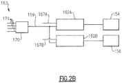
- FIG. 2B illustrates exemplary gate drive logic 163 for the gate drive 162 of control unit 140 of Figure 2A .
- Each of the first and second drive modules 162A is coupled to a respective enable signal line 167A, 167B to enable or disable the respective first and second gates 154, 156.
- Each of the first and second drive modules 162A is coupled to a modulation line 69.
- a point of regulation (POR) sensing module 170 is operable to sense a condition of such as voltage or current carried on POR lines 171.
- the POR lines 171 may correspond to each of three phases A-C and neutral N carried on output terminals 39 of the main stator windings 38 ( Figure 1 ), for example.
- the POR sensing module 170 is operable to generate a pulse width modulation (PWM) signal that is carried on the modulation line 69 to cause the exciter 136 to vary a desired voltage and/or current output of the synchronous machine 20.
- PWM pulse width modulation
- the gate drive 162 can be operable to detect an SRD event.
- Techniques for detection of an SRD event can include voltage or ripple detection, for example.
- detection of an SRD event can include measuring voltage and/or current at one or more of the nodes of the control unit 140, such as the first, second and/or third nodes N1, N2, N3.
- the gate drive 162 may be coupled to one or more sensors that observe voltage and/or current at one or more of the nodes, and may compare the observed values to a predetermined range or threshold to determine whether an SRD event has occurred, for example.
- the observed values may correspond to a build-up of voltage in the control unit 140 across the rectifier 146, for example.
- the gate drive 162 receives an indication that an SRD event has occurred from another portion of the synchronous machine 120 or another device.
- An SRD event can be caused by at least one of the rotating diodes 28 of the rotating rectifier 26 ( Figure 1 ), such as failure or deviation from a defined operating characteristic of the respective rotating diode 28.
- the first and second gates 154, 156 may be opened to move the synchronous machine 120 from an ON state to an OFF state.
- the SRD can cause current to be induced back into the exciter winding 136. This can cause voltages in the control unit 140 to build-up or otherwise increase.
- the capacitor 150 can absorb some voltage, but the voltage may continue to build up beyond a desired threshold.
- the TVS diode 152 can be utilized to clamp or otherwise maintain the voltage within a desired range.
- TVS diode 152 Prolonged inducement of current back into the exciter winding 136 may cause the TVS diode 152 to fail, however.
- TVS diodes can be omitted from the circuitry of the control unit 140 by incorporation of the gate drive 162 utilizing the techniques disclosed herein.
- FIGS 3A-3C illustrate the control unit 140 in various operating states or modes, with electrical connectivity or paths shown in solid lines and electrically disconnected portions or paths of the control unit 140 shown in dashed lines.
- Figure 4 shows an example state diagram 165 illustrating various operating modes of the control unit 140.
- the operating modes include at least a first operating mode 166A, a second operating mode 166B, and a third operating mode 166C.
- the first operating mode 166A may correspond to the open and closed electrical connections illustrated in Figure 3A .
- the second operating mode 166B may correspond to the open and closed electrical connections illustrated in Figure 3B
- the third operating mode may correspond to the open and closed electrical connections illustrated in Figure 3C .
- the control unit 140 includes a fourth operating mode 166D in which the exciter energy source, such as the PMG 134, is in an off state to de-energize the exciter 136 during normal operation.
- the control unit 140 is shown in the first operating mode 166A.
- the first and second drive modules 162A, 162B output respective first and second gate signals to cause the first and second gates 154, 156 to close.
- the first and second gates 154, 156 cause the PMG 134 to be electrically connected to the exciter winding 136, with the exciter winding 136 electrically in parallel with the rectifier 146 and the capacitor 150.
- the first and second gates 154, 156 are electrically connected in series with the exciter winding 136, and the first and second diodes 158, 160 are electrically disconnected from the exciter winding 136.
- the control unit 140 causes the exciter winding 136 to energize, thereby causing the rotating field winding 32 to induce a current in the main stator windings 38 ( Figure 1 ).
- FIG 6 illustrates a control unit 340 according to a third embodiment.
- the control unit 140 includes a third transistor or gate 359 in series with a resistance R1 (e.g., about 10 ohms) and a third diode 361.
- the third gate 359, resistance R1 and third diode 361 are connected between nodes N2 and N3.
- Gate drive 362 can include a third drive module 362C electrically coupled to the third gate 359 via a third gate drive signal line 364C to modulate the third gate 359 between open and closed states.
- the third gate 359 will be in the open state when the control unit 340 is switching normally between the first and second operating modes 166A, 166B ( Figure 4 ).
Landscapes
- Engineering & Computer Science (AREA)
- Power Engineering (AREA)
- Control Of Eletrric Generators (AREA)
Abstract
Description
- This disclosure relates generally to synchronous machines, and more specifically to protection or isolation of circuitry during operation.
- Synchronous machines are known. Synchronous machines include a stationary portion and a rotating portion, where the rotating portion and the stationary portion each have at least one winding. One application of synchronous machines is a generator arrangement for gas turbine engines to power the various components of the engine and/or aircraft.
- The synchronous machine includes a field winding on the rotating portion and an armature winding on the stationary portion. Current supplied to the field winding generates a magnetic field between the rotating portion and the stationary portion, causing current to be generated at the armature winding. The rotating portion typically includes one or more rotating diodes to rectify current to the field winding. During operation of the synchronous machine, one of the rotating diodes may become shorted or otherwise malfunction, sometimes referred to as a "shorted rotating diode" (SRD). In some arrangements, one or more portions of the stationary portion are electrically isolated from the SRD during an SRD event.
- An assembly engine according to an example of the present disclosure includes a synchronous machine including a rotating portion and a stationary portion, the rotating portion including at least one rotating diode coupled to a field winding, and the stationary portion including a stator winding and an exciter winding, and a control unit including a first gate and a second gate. The exciter winding is connected in series to the first gate and the second gate during a first operating mode to energize the exciter winding. The exciter winding is electrically connected in series to a first gate but is electrically disconnected from the second gate in a second, different operating mode to electrically disconnect the exciter winding from an exciter energy source.
- A synchronous machine and a method of operating a synchronous machine are also disclosed.
- The various features and advantages of disclosed embodiments will become apparent to those skilled in the art from the following detailed description. The drawings that accompany the detailed description can be briefly described as follows.
-
-
Figure 1 illustrates a synchronous machine. -
Figure 2A illustrates a control unit according to a first embodiment. -
Figure 2B illustrates exemplary gate drive logic of the control unit ofFigure 2A . -
Figure 3A illustrates the control unit ofFigure 2A in a first operating mode. -
Figure 3B illustrates the control unit ofFigure 2A in a second operating mode. -
Figure 3C illustrates the control unit ofFigure 2A in a third operating mode. -
Figure 4 illustrates a state diagram for a control unit. -
Figure 5 illustrates a control unit according to a second embodiment. -
Figure 6 illustrates a control unit according to a third embodiment. -
Figure 7 illustrates a control unit according to a fourth embodiment. - Like reference numbers and designations in the various drawings indicate like elements.
- The disclosed embodiments of a synchronous machine include a rotating rectifier protection circuit that is operable to electrically isolate components of the synchronous machine in response to an SRD event that may occur due to a faulty rotating diode.
-
Figure 1 illustrates asynchronous machine 20 that may be utilized to generate power. Thesynchronous machine 20 includes a rotatingportion 22 and astationary portion 24 that is arranged at least partially about the rotatingportion 22 to define an air gap. The rotatingportion 22 includes a rotatingrectifier 26 having one or more rotating diodes 28 (three pairs of diodes shown) coupled between one or more main rotor windings 30 and a rotating field winding 32. A supply of current from the main rotor windings 30 is communicated to the rotatingrectifier 26 to convert AC current to DC current, for example, which is supplied to the rotating field winding 32. - The
stationary portion 24 includes an exciter energy source such as a permanent magnet generator (PMG) 34. In other examples, the exciter energy source is a flux switching generator. Thestationary portion 24 also includes an exciter winding 36 and one or moremain stator windings 38. Although main rotor windings 30,PMG 34 andstator windings 38 are depicted as having three-phase windings, fewer or more than three phases can be utilized with the teachings herein, such as single-phase or two-phase arrangements. Additionally, although exciter winding 36 is depicted as having a single winding, more than one winding can be utilized, such as an exciter having three-phase windings. In the illustrated example ofFigure 1 ,PMG 34 is depicted as a full-wave arrangement (i.e., no neutral). In other examples, thePMG 34 comprises a half-wave arrangement (i.e., phases A, B, C and neutral). The PMG 34 may be a portion of another synchronous machine, and supplies an amount of current to the exciter winding 36. - During operation in a generator mode, a rotating magnetic field is generated by supplying current to the rotating field winding 32 which generates a rotating magnetic field to induce current in the
main stator windings 38 in response to relative rotation of the rotating andstationary portions - The
synchronous machine 20 includes a generator control relay orunit 40 provided with a rotating rectifier protection circuit. Thecontrol unit 40 is operable to control exciter winding 36 to selectively induce a current in, or otherwise energize, main rotor windings 30 in order to generate a magnetic field between rotating field winding 32 andstator windings 38. Thecontrol unit 40 has a first set ofinputs 42 relating to each of three phases A-C and neutral N carried on output terminals 39 of themain stator windings 38, a second set ofinputs 44 for windings of thePMG 34. Theinputs 44 are coupled to one ormore output terminals 45 of thePMG 34 viaphase lines 47. -
Figure 2A illustrates details of anexemplary control unit 140. In this disclosure, like reference numerals designate like elements where appropriate and reference numerals with the addition of one-hundred or multiples thereof designate modified elements that are understood to incorporate the same features and benefits of the corresponding original elements. - The
control unit 140 includes abridge rectifier 146. Therectifier 146 can include one or more pairs ofdiodes 148 coupled torespective output terminals 145 of thePMG 134 via phase lines 147. ThePMG 134 supplies voltage to therectifier 146, which rectifies AC current carried on phase lines 147 to DC current. Therectifier 146 communicates the DC current to exciter winding 136. In the illustrated example ofFigure 2A , thePMG 134 is a three-phase generator with phase lines 147 each coupled to respective pairs ofdiodes 148 of therectifier 146. In the alternative example ofFigure 6 ,control unit 240 is arranged withrectifier 246 including threediodes 248, with phase lines 247 coupling phases A, B, C torespective diodes 248, and a neutral line N ofPMG 234 connected to ground. - The
rectifier 146 is arranged in parallel with acapacitor 150. Theexciter winding 136 is connected in parallel with therectifier 146 and with thecapacitor 150. In some examples, therectifier 146 can be arranged in parallel with a transient-voltage-suppression (TVS) diode 152 (connections shown in dashed lines), sometimes referred to as a "transorb." TVS diodes can be utilized to "clamp" or otherwise maintain voltage within a desired range or value. Thecapacitor 150 andTVS diode 152 can be utilized to protect or isolate circuitry of thecontrol unit 140 during an SRD event, as discussed in more detail below. In other examples, the circuitry of thecontrol unit 140, including betweenPMG 134 and exciter winding 136, is free of any TVS diodes. Omission of TVS diodes can reduce system complexity, size, and cost, for example. - The
control unit 140 includes a first switch orgate 154 and a second switch orgate 156. Thecontrol unit 140 also includes afirst diode 158 and asecond diode 160. In the illustrated example ofFigure 2A , thefirst gate 154 and thesecond gate 156 are NMOS transistors. Other transistors, including other types of field-effect transistors (FET) and bipolar junction transistors, and other types of switch logic may also be utilized. - The
control unit 140 is arranged to define a plurality of nodes. The nodes include at least a first node N1, a second node N2, a third node N3, and a fourth node N4. In some examples, components of the first node N1 comprise therectifier 146, thecapacitor 150, theTVS diode 152, a drain terminal of thefirst gate 154, and a cathode of thesecond diode 160. In other examples, the circuitry of thecontrol unit 140 is free of any TVS diodes such that the first node N1 consists of therectifier 146, thecapacitor 150, the drain terminal of thefirst gate 154, and the cathode of thesecond diode 160. - Components of the second node N2 comprise a
first terminal 136A of the exciter winding 136, a cathode of thefirst diode 158, and a source terminal of thefirst gate 154. Components of the third node N3 comprise a second terminal 136B of the exciter winding 136, an anode of thesecond diode 160, and a drain terminal of the second transistor orgate 156. Components of the fourth node N4 include therectifier 146, thecapacitor 150, a source terminal of thesecond gate 156, and an anode of thefirst diode 158. In the illustrated example ofFigure 2A , node N4 is coupled to ground (shown schematically). In other examples, the ground (shown schematically) at node N4 is omitted. - The
control unit 140 includes agate drive 162 that is operable to independently control each of the first andsecond gates gate drive 162 includes afirst drive module 162A and asecond drive module 162B. Thefirst drive module 162A is electrically coupled to thefirst gate 154 via a first gatedrive signal line 164A, and thesecond drive module 162B is electrically coupled to thesecond gate 156 via a second gatedrive signal line 164B. - The
gate drive 162 is programmed with control logic to independently modulate each of the first andsecond gates gate drive 162 can include a processor and memory, for example. The processor may, for example only, be any type of known microprocessor having desired performance characteristics. The memory may, for example only, includes UVPROM, EEPROM, FLASH, RAM, ROM, DVD, CD, a hard drive, or other computer readable medium which may store data for operation of thecontrol unit 140 as described herein. In other examples, thegate drive 162 may comprise one or more digital and/or analog electrical devices to provide the desired solution. - The
control unit 140 is operable to simultaneously output and communicate a first gate signal carried on the first gatedrive signal line 164A to thefirst gate 154 and a second, different gate signal carried on the second gatedrive signal line 164B to thesecond gate 156 to independently move each of thegates respective gate control unit 140 can also hold each of the first andsecond gates second gates second drive modules second gates Figure 1 ) within a desired range or value. -
Figure 2B illustrates exemplarygate drive logic 163 for the gate drive 162 ofcontrol unit 140 ofFigure 2A . Each of the first andsecond drive modules 162A is coupled to a respective enablesignal line second gates second drive modules 162A is coupled to a modulation line 69. A point of regulation (POR)sensing module 170 is operable to sense a condition of such as voltage or current carried on POR lines 171. The POR lines 171 may correspond to each of three phases A-C and neutral N carried on output terminals 39 of the main stator windings 38 (Figure 1 ), for example. ThePOR sensing module 170 is operable to generate a pulse width modulation (PWM) signal that is carried on the modulation line 69 to cause theexciter 136 to vary a desired voltage and/or current output of thesynchronous machine 20. - The
gate drive 162 can be operable to detect an SRD event. Techniques for detection of an SRD event can include voltage or ripple detection, for example. In some examples, detection of an SRD event can include measuring voltage and/or current at one or more of the nodes of thecontrol unit 140, such as the first, second and/or third nodes N1, N2, N3. Thegate drive 162 may be coupled to one or more sensors that observe voltage and/or current at one or more of the nodes, and may compare the observed values to a predetermined range or threshold to determine whether an SRD event has occurred, for example. The observed values may correspond to a build-up of voltage in thecontrol unit 140 across therectifier 146, for example. In other examples, thegate drive 162 receives an indication that an SRD event has occurred from another portion of thesynchronous machine 120 or another device. - An SRD event can be caused by at least one of the
rotating diodes 28 of the rotating rectifier 26 (Figure 1 ), such as failure or deviation from a defined operating characteristic of the respectiverotating diode 28. During an SRD event, the first andsecond gates synchronous machine 120 from an ON state to an OFF state. The SRD can cause current to be induced back into the exciter winding 136. This can cause voltages in thecontrol unit 140 to build-up or otherwise increase. In the illustrated example, thecapacitor 150 can absorb some voltage, but the voltage may continue to build up beyond a desired threshold. TheTVS diode 152 can be utilized to clamp or otherwise maintain the voltage within a desired range. Prolonged inducement of current back into the exciter winding 136 may cause theTVS diode 152 to fail, however. TVS diodes can be omitted from the circuitry of thecontrol unit 140 by incorporation of thegate drive 162 utilizing the techniques disclosed herein. -
Figures 3A-3C illustrate thecontrol unit 140 in various operating states or modes, with electrical connectivity or paths shown in solid lines and electrically disconnected portions or paths of thecontrol unit 140 shown in dashed lines. -
Figure 4 shows an example state diagram 165 illustrating various operating modes of thecontrol unit 140. In the illustrated example ofFigure 4 , the operating modes include at least afirst operating mode 166A, asecond operating mode 166B, and athird operating mode 166C. In the illustrated example, thefirst operating mode 166A may correspond to the open and closed electrical connections illustrated inFigure 3A . Thesecond operating mode 166B may correspond to the open and closed electrical connections illustrated inFigure 3B , and the third operating mode may correspond to the open and closed electrical connections illustrated inFigure 3C . Thecontrol unit 140 includes afourth operating mode 166D in which the exciter energy source, such as thePMG 134, is in an off state to de-energize theexciter 136 during normal operation. In the illustrated example ofFigure 4 , the first, second, third andfourth operating modes 166A-166D are mutually exclusive. ThePOR sensing module 170 is operable to cause theexciter 136 to transition between each of theoperating modes lines Figure 2A ). - In the illustrated example of
Figure 3A , thecontrol unit 140 is shown in thefirst operating mode 166A. The first andsecond drive modules second gates second gates PMG 134 to be electrically connected to the exciter winding 136, with the exciter winding 136 electrically in parallel with therectifier 146 and thecapacitor 150. The first andsecond gates second diodes control unit 140 causes the exciter winding 136 to energize, thereby causing the rotating field winding 32 to induce a current in the main stator windings 38 (Figure 1 ). - In the illustrated example of
Figure 3B , thecontrol unit 140 is shown in thesecond operating mode 166B. The first andsecond drive modules second gates second gates PMG 134 to be electrically decoupled or disconnected from the exciter winding 136, which can cause the exciter winding 136 to de-energize the rotating portion 22 (Figure 1 ) after a period of time. Thecapacitor 150 may absorb some energy that is communicated back from the exciter winding 136. The first andsecond diodes second gates - To control the voltage observed by the load L (
Figure 1 ), thecontrol unit 140 may move between the first andsecond operating modes second operating modes synchronous machine 120, for example. For the purposes of this disclosure, the term "normal" means a condition in which an SRD event has not occurred. - In the illustrated example of
Figure 3C , thecontrol unit 140 is shown in thethird operating mode 166C. Thecontrol unit 140 may cause thesynchronous machine 120 to enter into thethird operating mode 166C in response to occurrence of an SRD event. Thethird operating mode 166C may correspond to a failure mode of thecontrol unit 140 orsynchronous machine 120, for example. For the purposes of this disclosure, the term "failure" means a condition in which an SRD event has occurred. - In the
third operating mode 166C, thefirst drive module 162A output respective first and second gate signals to cause thefirst gate 154 to close, and thesecond drive module 162B causes thesecond gate 156 to open. Thecontrol unit 140 causes thePMG 134 andrectifier 146 to be electrically decoupled or disconnected from the exciter winding 136 in response to closing thefirst gate 154 and opening thesecond gate 156, which can provide isolation or protection of components of thecontrol unit 140 from voltage increases that may be caused by the SRD. Thesecond diode 160 and thefirst gate 154 are electrically connected in series with the exciter winding 136, thefirst diode 158 and thesecond gate 156 are electrically disconnected from the exciter winding 136, and the exciter winding 136 is disconnected from thePMG 134. - In the
third operating mode 166C, current is looped back to the exciter winding 136, bypassing therectifier 146 and thecapacitor 150. Therectifier 146 andcapacitor 150 are electrically isolated from energy that is communicated back from the exciter winding 136, which prevents or otherwise reduces the amount of energy build-up in thecapacitor 150. This can reduce the sizing requirements of thecapacitor 150 and reduce system complexity. Also, TVS diodes can be omitted from the circuitry of thecontrol unit 140, which can reduce system weight and complexity. The first andsecond drive modules second gates synchronous machine 120 is serviced, for example. -
Figure 6 illustrates acontrol unit 340 according to a third embodiment. Thecontrol unit 140 includes a third transistor orgate 359 in series with a resistance R1 (e.g., about 10 ohms) and athird diode 361. Thethird gate 359, resistance R1 andthird diode 361 are connected between nodes N2 and N3.Gate drive 362 can include athird drive module 362C electrically coupled to thethird gate 359 via a third gatedrive signal line 364C to modulate thethird gate 359 between open and closed states. Thethird gate 359 will be in the open state when thecontrol unit 340 is switching normally between the first andsecond operating modes Figure 4 ). Thethird diode 361 prevents a body diode of thethird gate 359 from conducting during normal operation off time. Thegate drive 362 is operable to cause thethird gate 359 to close in thethird operating mode 166C, and thereby cause at least a portion of the current to flow through the resistance R1. -
Figure 7 illustrates a control unit 440 according to a fourth embodiment. In the illustrated embodiment ofFigure 7 , synchronous machine 420 is configured to have a generator mode and a starter mode. The synchronous machine 420 includes a three-phase exciter windings 436 including phases X, Y and Z. During the generator mode, thegate drive 462 causes switch S1 to close and switches S2-S4 to open to electrically couple phases X and Z of theexciter windings 436 to an exciter energy source (e.g.,PMG 134 ofFigure 2A ) via nodes N2 and N3. During the starter mode, thegate drive 462 causes switches S2-S4 to close and switch S1 to open to electrically couple phases X, Y and Z of theexciter windings 436 to a secondexciter energy source 468. The secondexciter energy source 468 can be operable to supply a quantity of three-phase alternating current, for example. - Although the different examples have a specific component shown in the illustrations, embodiments of this disclosure are not limited to those particular combinations. It is possible to use some of the components or features from one of the examples in combination with features or components from another one of the examples. It should also be understood that any particular quantities disclosed in the examples herein are provided for illustrative purposes only.
- Furthermore, the foregoing description shall be interpreted as illustrative and not in any limiting sense. A worker of ordinary skill in the art would understand that certain modifications could come within the scope of this disclosure. For these reasons, the following claims should be studied to determine the true scope and content of this disclosure.
Claims (15)
- An assembly comprising:a synchronous machine (20) including a rotating portion (22) and a stationary portion (24), the rotating portion (22) including at least one rotating diode (28) coupled to a field winding (32), and the stationary portion including a stator winding and an exciter winding (136);a control unit (140) including a first gate and a second gate;wherein the exciter winding (136) is connected in series to the first gate (154) and the second gate (156) during a first operating mode to energize the exciter winding (13 6); andwherein the exciter winding (136) is electrically connected in series to a first gate (154) but is electrically disconnected from the second gate (156) in a second, different operating mode to electrically disconnect the exciter winding (136)from an exciter energy source.
- The assembly as recited in claim 1, wherein the exciter energy source is electrically disconnected from the exciter winding in response to closing the first gate (154) and opening the second gate (156).
- The assembly as recited in claim 1 or 2, wherein the stationary portion includes a rectifier that electrically connects the exciter winding to the exciter energy source during the first operating mode.
- The assembly as recited in claim 3, wherein the exciter winding (136) is electrically in parallel with the rectifier and with a capacitor during the first operating mode, or
wherein the exciter energy source is a three-phase generator including phase lines each electrically coupled to a respective pair of diodes of the rectifier. - The assembly as recited in any preceding claim, wherein the first gate (154) and the second gate (156) are transistors, and/or
wherein circuitry between the exciter energy source and the exciter winding (136) is free of any transient voltage suppression diodes. - The assembly as recited in any preceding claim, wherein the control unit (140) is operable to simultaneously communicate a first gate signal to the first gate and a second, different gate signal to the second gate (156).
- The assembly as recited in claim 6, wherein the control unit (140) is operable to hold closed the first gate (154) during the second operating mode, and is operable to hold open the second gate (156) during the second operating mode, and preferably
wherein the second operating mode relates to a shorted rotating diode event caused by the at least one rotating diode. - The assembly as recited in any preceding claim, wherein:the stationary portion includes a first diode and a second diode;the first diode (158) and the second diode (160) are electrically disconnected from the exciter winding (136) during the first operating mode;the second diode (160) is electrically connected to the exciter winding (136), and the first diode (158) is electrically disconnected from the exciter winding (136) during the second operating mode; andthe first diode (158) and the second diode (160) are electrically connected in series to the exciter winding (136) during a third, different operating mode, and preferablywherein the exciter energy source is electrically disconnected from the exciter winding (136) in the third operating mode.
- A synchronous machine (20) comprising:a rotating portion including at least one rotating diode (28) coupled to a field winding (32);a stationary portion including a stator winding, an exciter winding (136), a bridge rectifier coupled to a permanent magnet generator, a capacitor, and a plurality of nodes, the plurality of nodes including a first node, a second node, a third node and a fourth node;a control unit (140) including a first gate, a second gate, a first diode, and a second diode;wherein components of the first node consist of the bridge rectifier, the capacitor, a drain terminal of the first gate, and a cathode of the second diode; andwherein components of the second node comprise a first terminal of the exciter winding, a cathode of the first diode, and a source terminal of the first gate;wherein components of the third node comprise a second terminal of the exciter winding, an anode of the second diode, and a drain terminal of the second gate;wherein components of the fourth node comprise the bridge rectifier, the capacitor, a source terminal of the second gate, and an anode of the first diode;wherein the exciter winding (136) is electrically connected in series to the first gate (154) and the second gate (156) during a first operating mode to energize the exciter winding (156); andwherein the exciter winding (136) is electrically connected in series to the first gate (154), but is electrically disconnected from the second gate (156) during a second, different operating mode to electrically disconnect the exciter winding (136) from the permanent magnet generator.
- A method of operating a synchronous machine, comprising:closing first (154) and second gates (156) to energize an exciter winding (136) in series between the first (154) and second gates (156); andopening the second gate (156), but closing the first gate (154) to electrically disconnect to the exciter winding (136) from a rectifier in response to a shorted rotating diode event.
- The method as recited in claim 10, wherein the rectifier is coupled to an exciter energy source, and the first gate (136) and the second gate (156) are transistors.
- The method as recited in claim 11, wherein circuitry between the exciter energy source and the exciter winding (136) is free of any transient voltage suppression diodes.
- The method as recited in claim 11, comprising opening the first (154) and second gates (156) to electrically disconnect the exciter winding (136) from the exciter energy source.
- The method as recited in claim 11, wherein phase lines of the exciter energy source are each coupled to a respective pair of diodes of the rectifier.
- The method as recited in any of claims 10 to 14, wherein the step of closing the first (154) and second gates (156) includes electrically connecting in parallel a capacitor with the exciter winding (136) and the rectifier, and preferably
wherein the step of opening the second gate (156) includes electrically connecting a first diode in series with the first gate (154) and the exciter winding (136).
Applications Claiming Priority (1)
| Application Number | Priority Date | Filing Date | Title |
|---|---|---|---|
| US15/675,090 US10469011B2 (en) | 2017-08-11 | 2017-08-11 | Shorted rotating diode protection for synchronous machines |
Publications (2)
| Publication Number | Publication Date |
|---|---|
| EP3444941A1 true EP3444941A1 (en) | 2019-02-20 |
| EP3444941B1 EP3444941B1 (en) | 2021-03-31 |
Family
ID=63209315
Family Applications (1)
| Application Number | Title | Priority Date | Filing Date |
|---|---|---|---|
| EP18188550.0A Active EP3444941B1 (en) | 2017-08-11 | 2018-08-10 | Shorted rotating diode protection for synchronous machines |
Country Status (2)
| Country | Link |
|---|---|
| US (2) | US10469011B2 (en) |
| EP (1) | EP3444941B1 (en) |
Families Citing this family (2)
| Publication number | Priority date | Publication date | Assignee | Title |
|---|---|---|---|---|
| US10469011B2 (en) * | 2017-08-11 | 2019-11-05 | Hamilton Sundstrand Corporation | Shorted rotating diode protection for synchronous machines |
| US12088108B2 (en) * | 2021-06-08 | 2024-09-10 | Hamilton Sundstrand Corporation | Smart power router and protection for medium voltage DC distribution |
Citations (2)
| Publication number | Priority date | Publication date | Assignee | Title |
|---|---|---|---|---|
| US20090167257A1 (en) * | 2008-01-02 | 2009-07-02 | Maddali Vijay K | Shorted rotating diode detection and protection |
| US20130128394A1 (en) * | 2010-02-05 | 2013-05-23 | Stefan Spannhake | Circuit Assembly for Overvoltage Limiting of An Excitation Coil of A Syncronous Machine Having Fast De-Excitation |
Family Cites Families (16)
| Publication number | Priority date | Publication date | Assignee | Title |
|---|---|---|---|---|
| US4486801A (en) | 1980-11-10 | 1984-12-04 | Sundstrand Corporation | Generator shorted diode protection system |
| US5508601A (en) | 1994-11-15 | 1996-04-16 | Sundstrand Corporation | Protection system for a shorted rectifying diode within a synchronous generator |
| DE19649790A1 (en) * | 1996-12-02 | 1998-06-04 | Bosch Gmbh Robert | Device for regulating the output voltage of a three-phase generator |
| US6111390A (en) * | 1998-01-20 | 2000-08-29 | Kokusan Kenki Co., Ltd. | Magneto-equipped power device |
| GB0221154D0 (en) * | 2002-09-12 | 2002-10-23 | Switched Reluctance Drives Ltd | A circuit for use with switched reluctance machines |
| US7106030B2 (en) * | 2004-01-14 | 2006-09-12 | Vanner, Inc. | Field excitation for an alternator |
| US7268552B1 (en) | 2004-06-21 | 2007-09-11 | United States Of America As Represented By The United States Department Of Energy | Capillary toroid cavity detector for high pressure NMR |
| US8134345B2 (en) * | 2005-11-29 | 2012-03-13 | General Electric Company | Cryogenic exciter |
| US7759909B2 (en) * | 2007-08-30 | 2010-07-20 | Infineon Technologies Ag | Generator control circuit |
| US8289005B2 (en) * | 2008-09-30 | 2012-10-16 | C.E. Niehoff & Co. | Field transient suppression system and method |
| US8487592B2 (en) * | 2010-02-10 | 2013-07-16 | Infineon Technologies Ag | Circuit and method for de-energizing a field coil |
| FR2976747B1 (en) * | 2011-06-15 | 2014-02-14 | Leroy Somer Moteurs | ALTERNATOR WITH VOLTAGE REGULATION |
| US8823208B2 (en) * | 2011-11-16 | 2014-09-02 | C. E. Niehoff & Co. | Self-energizing voltage regulator with improved transient recovery |
| CN102904515B (en) * | 2012-10-22 | 2015-03-04 | 中国矿业大学 | Control method for non-position sensor of switch reluctance generator |
| US9543876B2 (en) | 2013-06-20 | 2017-01-10 | Hamilton Sundstrand Corporation | Three phase flux switching generator in a three stage wound field synchronous machine |
| US10469011B2 (en) * | 2017-08-11 | 2019-11-05 | Hamilton Sundstrand Corporation | Shorted rotating diode protection for synchronous machines |
-
2017
- 2017-08-11 US US15/675,090 patent/US10469011B2/en active Active
-
2018
- 2018-08-10 EP EP18188550.0A patent/EP3444941B1/en active Active
-
2019
- 2019-09-10 US US16/566,062 patent/US11482955B2/en active Active
Patent Citations (2)
| Publication number | Priority date | Publication date | Assignee | Title |
|---|---|---|---|---|
| US20090167257A1 (en) * | 2008-01-02 | 2009-07-02 | Maddali Vijay K | Shorted rotating diode detection and protection |
| US20130128394A1 (en) * | 2010-02-05 | 2013-05-23 | Stefan Spannhake | Circuit Assembly for Overvoltage Limiting of An Excitation Coil of A Syncronous Machine Having Fast De-Excitation |
Also Published As
| Publication number | Publication date |
|---|---|
| EP3444941B1 (en) | 2021-03-31 |
| US20200007057A1 (en) | 2020-01-02 |
| US11482955B2 (en) | 2022-10-25 |
| US10469011B2 (en) | 2019-11-05 |
| US20190052204A1 (en) | 2019-02-14 |
Similar Documents
| Publication | Publication Date | Title |
|---|---|---|
| US6020711A (en) | Multiple winding channel, magnetic coupling-alterable reluctance electrical machines and their fault tolerant control | |
| EP3144186A1 (en) | Automobile power source device | |
| US12224690B2 (en) | Drive device and method for operating an electrical machine | |
| US10976762B2 (en) | Control of an electrical power system responsive to sensing a ground fault | |
| US20060091840A1 (en) | Circuit configuration and method for controlling an electric motor, in particular of a washing machine | |
| CN109245083B (en) | Power system and method of operating a power system | |
| US8427092B2 (en) | High voltage DC electric power generating system with permanent magnet generator protection | |
| US11482955B2 (en) | Shorted rotating diode protection for synchronous machines | |
| US20210021217A1 (en) | Fault-tolerant electrical drive | |
| JP7243490B2 (en) | Alternator drive system | |
| US9257877B2 (en) | Superconducting machine and method for the operation thereof | |
| McCrow et al. | Fault tolerant drives for safety critical applications | |
| US7638985B2 (en) | Self-excitation of switched reluctance generators during load bus faults | |
| US9240751B2 (en) | Phase current detection system | |
| US12424960B2 (en) | Activation system and method for operating an electric machine | |
| US11012021B2 (en) | Inverter device and control circuit therefor, and motor driving system | |
| US20210135447A1 (en) | Integrated circuit module for circuit breakers, relays and contactors | |
| CN114614688A (en) | Protection device for inverter, inverter system, and electric vehicle | |
| US8884590B2 (en) | Electricity generation device and permanent-magnet electric generator | |
| US12088108B2 (en) | Smart power router and protection for medium voltage DC distribution | |
| Atkinson et al. | Fault tolerant fuel pump drives for the all electric aircraft | |
| EP3255779B1 (en) | Reconfigurable multi-permanent magnet generator based power generating system | |
| US20250007437A1 (en) | Inverter for controlling an electrical machine, method of operating the inverter and safety control device | |
| US12206241B2 (en) | Redundant power supply, in particular for data centers, and method and computer program for the operation thereof | |
| JP2020156272A (en) | Rotating electric machine control device |
Legal Events
| Date | Code | Title | Description |
|---|---|---|---|
| PUAI | Public reference made under article 153(3) epc to a published international application that has entered the european phase |
Free format text: ORIGINAL CODE: 0009012 |
|
| STAA | Information on the status of an ep patent application or granted ep patent |
Free format text: STATUS: THE APPLICATION HAS BEEN PUBLISHED |
|
| AK | Designated contracting states |
Kind code of ref document: A1 Designated state(s): AL AT BE BG CH CY CZ DE DK EE ES FI FR GB GR HR HU IE IS IT LI LT LU LV MC MK MT NL NO PL PT RO RS SE SI SK SM TR |
|
| AX | Request for extension of the european patent |
Extension state: BA ME |
|
| STAA | Information on the status of an ep patent application or granted ep patent |
Free format text: STATUS: REQUEST FOR EXAMINATION WAS MADE |
|
| 17P | Request for examination filed |
Effective date: 20190808 |
|
| RBV | Designated contracting states (corrected) |
Designated state(s): AL AT BE BG CH CY CZ DE DK EE ES FI FR GB GR HR HU IE IS IT LI LT LU LV MC MK MT NL NO PL PT RO RS SE SI SK SM TR |
|
| GRAP | Despatch of communication of intention to grant a patent |
Free format text: ORIGINAL CODE: EPIDOSNIGR1 |
|
| STAA | Information on the status of an ep patent application or granted ep patent |
Free format text: STATUS: GRANT OF PATENT IS INTENDED |
|
| INTG | Intention to grant announced |
Effective date: 20200605 |
|
| GRAJ | Information related to disapproval of communication of intention to grant by the applicant or resumption of examination proceedings by the epo deleted |
Free format text: ORIGINAL CODE: EPIDOSDIGR1 |
|
| STAA | Information on the status of an ep patent application or granted ep patent |
Free format text: STATUS: REQUEST FOR EXAMINATION WAS MADE |
|
| GRAJ | Information related to disapproval of communication of intention to grant by the applicant or resumption of examination proceedings by the epo deleted |
Free format text: ORIGINAL CODE: EPIDOSDIGR1 |
|
| GRAP | Despatch of communication of intention to grant a patent |
Free format text: ORIGINAL CODE: EPIDOSNIGR1 |
|
| GRAP | Despatch of communication of intention to grant a patent |
Free format text: ORIGINAL CODE: EPIDOSNIGR1 |
|
| STAA | Information on the status of an ep patent application or granted ep patent |
Free format text: STATUS: GRANT OF PATENT IS INTENDED |
|
| INTC | Intention to grant announced (deleted) | ||
| INTG | Intention to grant announced |
Effective date: 20201029 |
|
| GRAS | Grant fee paid |
Free format text: ORIGINAL CODE: EPIDOSNIGR3 |
|
| GRAA | (expected) grant |
Free format text: ORIGINAL CODE: 0009210 |
|
| STAA | Information on the status of an ep patent application or granted ep patent |
Free format text: STATUS: THE PATENT HAS BEEN GRANTED |
|
| AK | Designated contracting states |
Kind code of ref document: B1 Designated state(s): AL AT BE BG CH CY CZ DE DK EE ES FI FR GB GR HR HU IE IS IT LI LT LU LV MC MK MT NL NO PL PT RO RS SE SI SK SM TR |
|
| REG | Reference to a national code |
Ref country code: GB Ref legal event code: FG4D Ref country code: CH Ref legal event code: EP |
|
| REG | Reference to a national code |
Ref country code: DE Ref legal event code: R096 Ref document number: 602018014632 Country of ref document: DE Ref country code: AT Ref legal event code: REF Ref document number: 1378088 Country of ref document: AT Kind code of ref document: T Effective date: 20210415 |
|
| REG | Reference to a national code |
Ref country code: IE Ref legal event code: FG4D |
|
| REG | Reference to a national code |
Ref country code: LT Ref legal event code: MG9D |
|
| PG25 | Lapsed in a contracting state [announced via postgrant information from national office to epo] |
Ref country code: NO Free format text: LAPSE BECAUSE OF FAILURE TO SUBMIT A TRANSLATION OF THE DESCRIPTION OR TO PAY THE FEE WITHIN THE PRESCRIBED TIME-LIMIT Effective date: 20210630 Ref country code: FI Free format text: LAPSE BECAUSE OF FAILURE TO SUBMIT A TRANSLATION OF THE DESCRIPTION OR TO PAY THE FEE WITHIN THE PRESCRIBED TIME-LIMIT Effective date: 20210331 Ref country code: HR Free format text: LAPSE BECAUSE OF FAILURE TO SUBMIT A TRANSLATION OF THE DESCRIPTION OR TO PAY THE FEE WITHIN THE PRESCRIBED TIME-LIMIT Effective date: 20210331 Ref country code: BG Free format text: LAPSE BECAUSE OF FAILURE TO SUBMIT A TRANSLATION OF THE DESCRIPTION OR TO PAY THE FEE WITHIN THE PRESCRIBED TIME-LIMIT Effective date: 20210630 |
|
| PG25 | Lapsed in a contracting state [announced via postgrant information from national office to epo] |
Ref country code: RS Free format text: LAPSE BECAUSE OF FAILURE TO SUBMIT A TRANSLATION OF THE DESCRIPTION OR TO PAY THE FEE WITHIN THE PRESCRIBED TIME-LIMIT Effective date: 20210331 Ref country code: LV Free format text: LAPSE BECAUSE OF FAILURE TO SUBMIT A TRANSLATION OF THE DESCRIPTION OR TO PAY THE FEE WITHIN THE PRESCRIBED TIME-LIMIT Effective date: 20210331 Ref country code: SE Free format text: LAPSE BECAUSE OF FAILURE TO SUBMIT A TRANSLATION OF THE DESCRIPTION OR TO PAY THE FEE WITHIN THE PRESCRIBED TIME-LIMIT Effective date: 20210331 |
|
| REG | Reference to a national code |
Ref country code: NL Ref legal event code: MP Effective date: 20210331 |
|
| REG | Reference to a national code |
Ref country code: AT Ref legal event code: MK05 Ref document number: 1378088 Country of ref document: AT Kind code of ref document: T Effective date: 20210331 |
|
| PG25 | Lapsed in a contracting state [announced via postgrant information from national office to epo] |
Ref country code: AT Free format text: LAPSE BECAUSE OF FAILURE TO SUBMIT A TRANSLATION OF THE DESCRIPTION OR TO PAY THE FEE WITHIN THE PRESCRIBED TIME-LIMIT Effective date: 20210331 Ref country code: NL Free format text: LAPSE BECAUSE OF FAILURE TO SUBMIT A TRANSLATION OF THE DESCRIPTION OR TO PAY THE FEE WITHIN THE PRESCRIBED TIME-LIMIT Effective date: 20210331 Ref country code: SM Free format text: LAPSE BECAUSE OF FAILURE TO SUBMIT A TRANSLATION OF THE DESCRIPTION OR TO PAY THE FEE WITHIN THE PRESCRIBED TIME-LIMIT Effective date: 20210331 Ref country code: LT Free format text: LAPSE BECAUSE OF FAILURE TO SUBMIT A TRANSLATION OF THE DESCRIPTION OR TO PAY THE FEE WITHIN THE PRESCRIBED TIME-LIMIT Effective date: 20210331 Ref country code: CZ Free format text: LAPSE BECAUSE OF FAILURE TO SUBMIT A TRANSLATION OF THE DESCRIPTION OR TO PAY THE FEE WITHIN THE PRESCRIBED TIME-LIMIT Effective date: 20210331 Ref country code: EE Free format text: LAPSE BECAUSE OF FAILURE TO SUBMIT A TRANSLATION OF THE DESCRIPTION OR TO PAY THE FEE WITHIN THE PRESCRIBED TIME-LIMIT Effective date: 20210331 |
|
| PG25 | Lapsed in a contracting state [announced via postgrant information from national office to epo] |
Ref country code: IS Free format text: LAPSE BECAUSE OF FAILURE TO SUBMIT A TRANSLATION OF THE DESCRIPTION OR TO PAY THE FEE WITHIN THE PRESCRIBED TIME-LIMIT Effective date: 20210731 Ref country code: PL Free format text: LAPSE BECAUSE OF FAILURE TO SUBMIT A TRANSLATION OF THE DESCRIPTION OR TO PAY THE FEE WITHIN THE PRESCRIBED TIME-LIMIT Effective date: 20210331 Ref country code: PT Free format text: LAPSE BECAUSE OF FAILURE TO SUBMIT A TRANSLATION OF THE DESCRIPTION OR TO PAY THE FEE WITHIN THE PRESCRIBED TIME-LIMIT Effective date: 20210802 Ref country code: SK Free format text: LAPSE BECAUSE OF FAILURE TO SUBMIT A TRANSLATION OF THE DESCRIPTION OR TO PAY THE FEE WITHIN THE PRESCRIBED TIME-LIMIT Effective date: 20210331 Ref country code: RO Free format text: LAPSE BECAUSE OF FAILURE TO SUBMIT A TRANSLATION OF THE DESCRIPTION OR TO PAY THE FEE WITHIN THE PRESCRIBED TIME-LIMIT Effective date: 20210331 |
|
| REG | Reference to a national code |
Ref country code: DE Ref legal event code: R097 Ref document number: 602018014632 Country of ref document: DE |
|
| PG25 | Lapsed in a contracting state [announced via postgrant information from national office to epo] |
Ref country code: ES Free format text: LAPSE BECAUSE OF FAILURE TO SUBMIT A TRANSLATION OF THE DESCRIPTION OR TO PAY THE FEE WITHIN THE PRESCRIBED TIME-LIMIT Effective date: 20210331 Ref country code: AL Free format text: LAPSE BECAUSE OF FAILURE TO SUBMIT A TRANSLATION OF THE DESCRIPTION OR TO PAY THE FEE WITHIN THE PRESCRIBED TIME-LIMIT Effective date: 20210331 Ref country code: DK Free format text: LAPSE BECAUSE OF FAILURE TO SUBMIT A TRANSLATION OF THE DESCRIPTION OR TO PAY THE FEE WITHIN THE PRESCRIBED TIME-LIMIT Effective date: 20210331 |
|
| PLBE | No opposition filed within time limit |
Free format text: ORIGINAL CODE: 0009261 |
|
| STAA | Information on the status of an ep patent application or granted ep patent |
Free format text: STATUS: NO OPPOSITION FILED WITHIN TIME LIMIT |
|
| 26N | No opposition filed |
Effective date: 20220104 |
|
| REG | Reference to a national code |
Ref country code: CH Ref legal event code: PL |
|
| PG25 | Lapsed in a contracting state [announced via postgrant information from national office to epo] |
Ref country code: MC Free format text: LAPSE BECAUSE OF FAILURE TO SUBMIT A TRANSLATION OF THE DESCRIPTION OR TO PAY THE FEE WITHIN THE PRESCRIBED TIME-LIMIT Effective date: 20210331 |
|
| REG | Reference to a national code |
Ref country code: BE Ref legal event code: MM Effective date: 20210831 |
|
| PG25 | Lapsed in a contracting state [announced via postgrant information from national office to epo] |
Ref country code: LI Free format text: LAPSE BECAUSE OF NON-PAYMENT OF DUE FEES Effective date: 20210831 Ref country code: CH Free format text: LAPSE BECAUSE OF NON-PAYMENT OF DUE FEES Effective date: 20210831 |
|
| PG25 | Lapsed in a contracting state [announced via postgrant information from national office to epo] |
Ref country code: IS Free format text: LAPSE BECAUSE OF FAILURE TO SUBMIT A TRANSLATION OF THE DESCRIPTION OR TO PAY THE FEE WITHIN THE PRESCRIBED TIME-LIMIT Effective date: 20210731 Ref country code: LU Free format text: LAPSE BECAUSE OF NON-PAYMENT OF DUE FEES Effective date: 20210810 |
|
| PG25 | Lapsed in a contracting state [announced via postgrant information from national office to epo] |
Ref country code: IT Free format text: LAPSE BECAUSE OF FAILURE TO SUBMIT A TRANSLATION OF THE DESCRIPTION OR TO PAY THE FEE WITHIN THE PRESCRIBED TIME-LIMIT Effective date: 20210331 Ref country code: IE Free format text: LAPSE BECAUSE OF NON-PAYMENT OF DUE FEES Effective date: 20210810 Ref country code: BE Free format text: LAPSE BECAUSE OF NON-PAYMENT OF DUE FEES Effective date: 20210831 |
|
| P01 | Opt-out of the competence of the unified patent court (upc) registered |
Effective date: 20230522 |
|
| PG25 | Lapsed in a contracting state [announced via postgrant information from national office to epo] |
Ref country code: CY Free format text: LAPSE BECAUSE OF FAILURE TO SUBMIT A TRANSLATION OF THE DESCRIPTION OR TO PAY THE FEE WITHIN THE PRESCRIBED TIME-LIMIT Effective date: 20210331 |
|
| PG25 | Lapsed in a contracting state [announced via postgrant information from national office to epo] |
Ref country code: HU Free format text: LAPSE BECAUSE OF FAILURE TO SUBMIT A TRANSLATION OF THE DESCRIPTION OR TO PAY THE FEE WITHIN THE PRESCRIBED TIME-LIMIT; INVALID AB INITIO Effective date: 20180810 Ref country code: GR Free format text: LAPSE BECAUSE OF FAILURE TO SUBMIT A TRANSLATION OF THE DESCRIPTION OR TO PAY THE FEE WITHIN THE PRESCRIBED TIME-LIMIT Effective date: 20210331 |
|
| PG25 | Lapsed in a contracting state [announced via postgrant information from national office to epo] |
Ref country code: MK Free format text: LAPSE BECAUSE OF FAILURE TO SUBMIT A TRANSLATION OF THE DESCRIPTION OR TO PAY THE FEE WITHIN THE PRESCRIBED TIME-LIMIT Effective date: 20210331 |
|
| PG25 | Lapsed in a contracting state [announced via postgrant information from national office to epo] |
Ref country code: MT Free format text: LAPSE BECAUSE OF FAILURE TO SUBMIT A TRANSLATION OF THE DESCRIPTION OR TO PAY THE FEE WITHIN THE PRESCRIBED TIME-LIMIT Effective date: 20210331 |
|
| PGFP | Annual fee paid to national office [announced via postgrant information from national office to epo] |
Ref country code: DE Payment date: 20250724 Year of fee payment: 8 |
|
| PGFP | Annual fee paid to national office [announced via postgrant information from national office to epo] |
Ref country code: GB Payment date: 20250725 Year of fee payment: 8 |
|
| PGFP | Annual fee paid to national office [announced via postgrant information from national office to epo] |
Ref country code: FR Payment date: 20250725 Year of fee payment: 8 |
|
| PG25 | Lapsed in a contracting state [announced via postgrant information from national office to epo] |
Ref country code: TR Free format text: LAPSE BECAUSE OF FAILURE TO SUBMIT A TRANSLATION OF THE DESCRIPTION OR TO PAY THE FEE WITHIN THE PRESCRIBED TIME-LIMIT Effective date: 20210331 |