EP3444837A1 - Method for obtaining the absorption position, mass and rigidity of a particle - Google Patents
Method for obtaining the absorption position, mass and rigidity of a particle Download PDFInfo
- Publication number
- EP3444837A1 EP3444837A1 EP17710586.3A EP17710586A EP3444837A1 EP 3444837 A1 EP3444837 A1 EP 3444837A1 EP 17710586 A EP17710586 A EP 17710586A EP 3444837 A1 EP3444837 A1 EP 3444837A1
- Authority
- EP
- European Patent Office
- Prior art keywords
- mass
- resonator
- rigidity
- functional
- values
- Prior art date
- Legal status (The legal status is an assumption and is not a legal conclusion. Google has not performed a legal analysis and makes no representation as to the accuracy of the status listed.)
- Granted
Links
Images



Classifications
-
- G—PHYSICS
- G01—MEASURING; TESTING
- G01G—WEIGHING
- G01G3/00—Weighing apparatus characterised by the use of elastically-deformable members, e.g. spring balances
- G01G3/12—Weighing apparatus characterised by the use of elastically-deformable members, e.g. spring balances wherein the weighing element is in the form of a solid body stressed by pressure or tension during weighing
- G01G3/16—Weighing apparatus characterised by the use of elastically-deformable members, e.g. spring balances wherein the weighing element is in the form of a solid body stressed by pressure or tension during weighing measuring variations of frequency of oscillations of the body
-
- G—PHYSICS
- G01—MEASURING; TESTING
- G01N—INVESTIGATING OR ANALYSING MATERIALS BY DETERMINING THEIR CHEMICAL OR PHYSICAL PROPERTIES
- G01N15/00—Investigating characteristics of particles; Investigating permeability, pore-volume or surface-area of porous materials
- G01N15/10—Investigating individual particles
- G01N15/1023—Microstructural devices for non-optical measurement
-
- G—PHYSICS
- G01—MEASURING; TESTING
- G01N—INVESTIGATING OR ANALYSING MATERIALS BY DETERMINING THEIR CHEMICAL OR PHYSICAL PROPERTIES
- G01N5/00—Analysing materials by weighing, e.g. weighing small particles separated from a gas or liquid
- G01N5/02—Analysing materials by weighing, e.g. weighing small particles separated from a gas or liquid by absorbing or adsorbing components of a material and determining change of weight of the adsorbent, e.g. determining moisture content
-
- H—ELECTRICITY
- H01—ELECTRIC ELEMENTS
- H01J—ELECTRIC DISCHARGE TUBES OR DISCHARGE LAMPS
- H01J49/00—Particle spectrometers or separator tubes
- H01J49/0027—Methods for using particle spectrometers
- H01J49/0036—Step by step routines describing the handling of the data generated during a measurement
-
- H—ELECTRICITY
- H01—ELECTRIC ELEMENTS
- H01J—ELECTRIC DISCHARGE TUBES OR DISCHARGE LAMPS
- H01J49/00—Particle spectrometers or separator tubes
- H01J49/26—Mass spectrometers or separator tubes
-
- G—PHYSICS
- G01—MEASURING; TESTING
- G01N—INVESTIGATING OR ANALYSING MATERIALS BY DETERMINING THEIR CHEMICAL OR PHYSICAL PROPERTIES
- G01N15/00—Investigating characteristics of particles; Investigating permeability, pore-volume or surface-area of porous materials
- G01N2015/0038—Investigating nanoparticles
-
- G—PHYSICS
- G01—MEASURING; TESTING
- G01N—INVESTIGATING OR ANALYSING MATERIALS BY DETERMINING THEIR CHEMICAL OR PHYSICAL PROPERTIES
- G01N15/00—Investigating characteristics of particles; Investigating permeability, pore-volume or surface-area of porous materials
- G01N15/10—Investigating individual particles
- G01N2015/1021—Measuring mass of individual particles
Definitions
- the present invention relates to mass spectrometry, in particular to the use of micro-cantilevers or bridges and their different vibration modes for obtaining parameters of interest, such as mass.
- Mass spectrometry very accurately measures the mass-to-charge ratio in molecular species between 100 Da and 100 kDa.
- classic methods do not offer sufficient efficiency with greater particle masses, such as cells, bacteria or viruses.
- New nanoelectromechanical systems such as cantilevers or bridges enable the mass of intact objects greater than 100 kDa to be measured, which means that these structures are considered especially appropriate for studying biological complexes and nanoparticles.
- the sample is introduced by means of an electrospray ionization (ESI) system and the resulting ions are guided by means of an electrostatic system towards a high vacuum chamber ( ⁇ ;10 -5 Torr) where the resonator is located.
- ESI electrospray ionization
- matrix-assisted laser desorption/ionization may be used to carry the sample to the resonator.
- MALDI matrix-assisted laser desorption/ionization
- the analysis of the data is simplified.
- the deconvolution of the absorption position throughout the NEMS and of the mass requires simultaneous measurement of at least two vibration modes, as proposed by Dohn et al. in "Mass and position determination of attached particles on cantilever based mass sensors", Review of Scientific Instruments 78, 103303, 2007 ) and is described in patent application US2014/0156224 .
- these methods do not enable the rigidity to be measured, which is a parameter that has been ignored to date as it is considered to have no influence when calculating mass.
- the present invention overcomes the technical prejudice described above and goes a step further in calculating parameters of interest by including the rigidity of particles, which is of great interest in the study of cells and other biological compounds that change state without significantly changing the mass (for example, healthy cells vs. cancer cells).
- the invention consists of a method for obtaining the absorption position, mass and rigidity of a particle deposited on the surface of a nanoelectromechanical resonator (cantilever or bridge) based on the changes in frequency of 3 or 4 flexural vibration modes.
- the particles may be inorganic, virus, bacteria, protein or cell particles.
- the mass spectrometer (MS) used may be seen in Figure 1 .
- the MS is made up of three differentiated vacuum chambers.
- the first chamber (1) is at atmospheric pressure and connected to the second by means of a hot capillary (8).
- the second chamber (2) is at 10 mbar and connected to the third by means of a skimmer and a microhole (100 ⁇ m) (4).
- the third chamber is at 0.1 mbar and contains the nanoelectromechanical resonator (5), which may be a cantilever or bridge.
- an electrospray ionization system responsible for sending the sample to the sensors.
- the ESI is made up of a bottle (7) with the dissolution and particles (inorganic, viral, etc.) of interest in suspension and a polyether ether ketone (PEEK) capillary (6).
- the dissolution is sent to the end of the capillary increasing the pressure in the bottle.
- a high voltage 3-5 kV
- a micro-jet ejects from the point of the cone from which small micro-droplets emerge that are positively charged (if the high voltage is positive, and negative if the high voltage is negative), which contain the dissolution and particles of interest.
- the micro-droplets generated in the first chamber (1) are sent to the second chamber (next differential vacuum) (2) where there is the hot capillary (8).
- the inner diameter of the hot capillary is between 400 and 500 ⁇ m and the temperature thereof is fixed between 150 and 300°, which favours the evaporation of the dissolution and prevents the particles from sticking to the walls by means of thermal agitation.
- the positively charged droplets lose part of their mass but not their charge, which means that these are progressively divided into smaller drops.
- the breaking point of a droplet into daughter droplets is caused when the Rayleigh criterion is reached, which is when the surface tension of the liquid and the repulsion caused by the positive charges (or negative in the case that the high voltage is negative) are in equilibrium.
- the particles enter the third chamber (3), or third differential vacuum, through a hole with a diameter of 100 ⁇ m.
- the nanoelectromechanical resonator (5) is in the third vacuum differential.
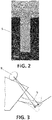
- the resonator is a bridge or cantilever as shown in figure 2 .
- the third chamber (3) has two optical windows that enable the natural frequency of the resonator oscillation to be measured using the beam deflection method ( figure 3 ).
- the laser (10) focuses on the resonator in the area where the product of the slopes of the vibration modes used is at a maximum by means of micro-positioners XYZ and the beam reflected is collected by a photodetector (9).
- the cantilever is excited by a piezoelectric element.
- a particle reaches the surface of the resonator, there is a change in the frequency corresponding to each vibration mode.
- the values of ⁇ 0 , ⁇ m and ⁇ s are found by numerical calculation, which maximise the probability density function.
- JPDF ⁇ ⁇ e ⁇ ⁇ ⁇ ⁇ M ⁇ ⁇ 1 ⁇ ⁇ ⁇ M T 2 2 ⁇ N / 2
- JPDF ⁇ ⁇ e ⁇ ⁇ ⁇ ⁇ M ⁇ 1 ⁇ ⁇ ⁇ M T 2 2 ⁇ N / 2
- the change in vibration frequency may be measured in several ways.
- a LASER is focused on the resonator in the area where the product of the slope of the vibration modes used is maximised.
- the reflected beam is detected by a 4 quadrant photo detector (or similar photodetector), which is known in the state of the art of beam deflection.
- the signal from the photodetector is preamplified and sent to an amplifier, preferably of the Lock-in type (a type of amplifier that can extract signals from incredibly noisy media).
- a piezoelectric material located below the resonator is used to carry out a sweep around the frequencies of interest in order to obtain the characteristic frequencies and phases of the resonator.
- the frequencies and phases obtained in the point about are used to configure the phase lock loops (PLLs), which monitor the corresponding frequencies over time.
- PLLs phase lock loops
- f n is the average of the frequency over the time corresponding to the mode n after absorption and f 0 n is the average of the frequency over the time corresponding to the mode n before absorption.
- ⁇ ⁇ s ⁇ m
- C n ( ⁇ 0 , ⁇ ) are given by:
- ⁇ n ( ⁇ 0 , ⁇ ) is given by:
- ⁇ n ⁇ 0 ⁇ ⁇ m ⁇ ⁇ n ⁇ 0 2 + ⁇ 1 ⁇ n 4 d 2 ⁇ n ⁇ 0 d ⁇ 2 2
- Figure 4 is obtained by following the second method for gold nanoparticles of 100nm with a nominal diameter. 174 absorptions of said nanoparticles were measured on the surface of a cantilever. Frequency changes in the first 3 flexural modes were stored and the second method described above was used to extract the mass, position and rigidity of the gold nanoparticles.
- the graph of the mass also shows the distribution provided by the manufacturer (Sigma Aldrich, segment with continuous line) and the distribution of the mass obtained without taking into account the rigidity (method described in the state of the art) where a displacement in the distribution of the mass towards smaller values when rigidity is not taken into account may be clearly seen.
- the graph also shows that the data that include the rigidity effect fit better with the distribution of the mass provided by the manufacturer, such that the method of the invention presents the additional advantage of improving the measurements of the mass parameter.
- ⁇ is a direct measurement and is proportional to the rigidity of the adsorbate.
Landscapes
- Chemical & Material Sciences (AREA)
- Analytical Chemistry (AREA)
- General Physics & Mathematics (AREA)
- Physics & Mathematics (AREA)
- Biochemistry (AREA)
- Life Sciences & Earth Sciences (AREA)
- Health & Medical Sciences (AREA)
- General Health & Medical Sciences (AREA)
- Immunology (AREA)
- Pathology (AREA)
- Dispersion Chemistry (AREA)
- Other Investigation Or Analysis Of Materials By Electrical Means (AREA)
- Solid-Sorbent Or Filter-Aiding Compositions (AREA)
Abstract
Description
- The present invention relates to mass spectrometry, in particular to the use of micro-cantilevers or bridges and their different vibration modes for obtaining parameters of interest, such as mass.
- Mass spectrometry (MS) very accurately measures the mass-to-charge ratio in molecular species between 100 Da and 100 kDa. However, classic methods do not offer sufficient efficiency with greater particle masses, such as cells, bacteria or viruses. New nanoelectromechanical systems (NEMS) such as cantilevers or bridges enable the mass of intact objects greater than 100 kDa to be measured, which means that these structures are considered especially appropriate for studying biological complexes and nanoparticles. In nanoelectromechanical systems mass spectrometry, the sample is introduced by means of an electrospray ionization (ESI) system and the resulting ions are guided by means of an electrostatic system towards a high vacuum chamber (<;10-5 Torr) where the resonator is located. Alternatively, matrix-assisted laser desorption/ionization (MALDI) may be used to carry the sample to the resonator. As the sample is absorbed by the resonator, sudden changes take place in the resonance frequency thereof, changes that are proportional to the mass of said particle with a proportionality constant that depends on the absorption position. Given that resonance is independent of the charge of the particle, the analysis of the data is simplified. The deconvolution of the absorption position throughout the NEMS and of the mass requires simultaneous measurement of at least two vibration modes, as proposed by Dohn et al. in "Mass and position determination of attached particles on cantilever based mass sensors", Review of Scientific Instruments 78, 103303, 2007) and is described in patent application
US2014/0156224 . However, these methods do not enable the rigidity to be measured, which is a parameter that has been ignored to date as it is considered to have no influence when calculating mass. - The present invention overcomes the technical prejudice described above and goes a step further in calculating parameters of interest by including the rigidity of particles, which is of great interest in the study of cells and other biological compounds that change state without significantly changing the mass (for example, healthy cells vs. cancer cells).
- As such, the invention consists of a method for obtaining the absorption position, mass and rigidity of a particle deposited on the surface of a nanoelectromechanical resonator (cantilever or bridge) based on the changes in frequency of 3 or 4 flexural vibration modes. The particles may be inorganic, virus, bacteria, protein or cell particles.
- In order to assist in a better understanding of the characteristics of the invention according to a preferred exemplary embodiment thereof and to complement this description, the following figures are attached constituting an integral part of the same, which, by way of illustration and not limitation, represent the following:
-
Figure 1 is a diagram of a mass spectrometry system that may be used to carry out the method of the invention. -
Figure 2 shows the micro-cantilever in greater detail. -
Figure 3 is a schematic drawing of the beam deflection technique used to measure the resonance frequencies. -
Figure 4 is a graph showing the mass of particles taking into account the rigidity compared to the mass calculated without taking into account the rigidity and the mass provided by the manufacturer (continuous line). -
Figure 5 is a graph of the ration between the rigidity term and the mass term
- The method of the invention enables the absorption position ξ 0, the mass term


- The mass spectrometer (MS) used may be seen in
Figure 1 . The MS is made up of three differentiated vacuum chambers. The first chamber (1) is at atmospheric pressure and connected to the second by means of a hot capillary (8). The second chamber (2) is at 10 mbar and connected to the third by means of a skimmer and a microhole (100 µm) (4). The third chamber is at 0.1 mbar and contains the nanoelectromechanical resonator (5), which may be a cantilever or bridge. In the section at atmospheric pressure there is an electrospray ionization system responsible for sending the sample to the sensors. The ESI is made up of a bottle (7) with the dissolution and particles (inorganic, viral, etc.) of interest in suspension and a polyether ether ketone (PEEK) capillary (6). The dissolution is sent to the end of the capillary increasing the pressure in the bottle. When the first drop reaches the end of the capillary, a high voltage (3-5 kV) is applied, generating the known Taylor cone. A micro-jet ejects from the point of the cone from which small micro-droplets emerge that are positively charged (if the high voltage is positive, and negative if the high voltage is negative), which contain the dissolution and particles of interest. The micro-droplets generated in the first chamber (1) are sent to the second chamber (next differential vacuum) (2) where there is the hot capillary (8). The inner diameter of the hot capillary is between 400 and 500 µm and the temperature thereof is fixed between 150 and 300°, which favours the evaporation of the dissolution and prevents the particles from sticking to the walls by means of thermal agitation. The positively charged droplets lose part of their mass but not their charge, which means that these are progressively divided into smaller drops. The breaking point of a droplet into daughter droplets is caused when the Rayleigh criterion is reached, which is when the surface tension of the liquid and the repulsion caused by the positive charges (or negative in the case that the high voltage is negative) are in equilibrium. Lastly, the dissolution evaporates completely, leaving only the particles of interest. The particles enter the third chamber (3), or third differential vacuum, through a hole with a diameter of 100 µm. The nanoelectromechanical resonator (5) is in the third vacuum differential. In a particular implementation, the resonator is a bridge or cantilever as shown infigure 2 . The third chamber (3) has two optical windows that enable the natural frequency of the resonator oscillation to be measured using the beam deflection method (figure 3 ). The laser (10) focuses on the resonator in the area where the product of the slopes of the vibration modes used is at a maximum by means of micro-positioners XYZ and the beam reflected is collected by a photodetector (9). The cantilever is excited by a piezoelectric element. When a particle reaches the surface of the resonator, there is a change in the frequency corresponding to each vibration mode. Based on the relative frequency changes, the values of ξ 0, Δ m and Δ s are found by numerical calculation, which maximise the probability density function.
- The change in vibration frequency may be measured in several ways. In a preferred example, a LASER is focused on the resonator in the area where the product of the slope of the vibration modes used is maximised. The reflected beam is detected by a 4 quadrant photo detector (or similar photodetector), which is known in the state of the art of beam deflection. Then, the signal from the photodetector is preamplified and sent to an amplifier, preferably of the Lock-in type (a type of amplifier that can extract signals from incredibly noisy media). A piezoelectric material located below the resonator is used to carry out a sweep around the frequencies of interest in order to obtain the characteristic frequencies and phases of the resonator. The frequencies and phases obtained in the point about are used to configure the phase lock loops (PLLs), which monitor the corresponding frequencies over time. When a particle reaches the surface of the resonator, there is a change in the resonance frequencies Δ fn. This change is registered by the PLLs. The changes in frequency are stored and, based on the same, the changes in relative frequency are calculated using the following formula:

- Where fn is the average of the frequency over the time corresponding to the mode n after absorption and f 0n is the average of the frequency over the time corresponding to the mode n before absorption. In this way, the relative changes of each vibration mode are obtained depending on the time and the standard deviation thereof.
- In order to obtain the absorption position, mass and rigidity of the adsorbed particle based on these data, which have been stored, the following steps must be carried out:
- 1. The standard deviation of the relative frequency change of each mode σn and the values of the relative frequency change corresponding to adsorption µn is calculated based on the data stored.
- 2. The following probability density function is formed based on the values of µn and σn for the N modes used (N=3 or N=4) which depend on three variables ξ 0, Δ m and Δ s :


M = (µ 1,µ 2,...,µN ) and Σ is the covariance matrix given by:
- 3. The values of ξ 0, Δ m and Δ s that maximise the probability density function JPDF(Ω̂) is found. At this point, a person skilled in the art will recognise that there are several methods for obtaining the values of ξ 0, Δ m and Δ s that maximise the probability density function JPDF(Ω̂). Two of them are proposed below.
- The following functional is formed:

- Functional F is numerically minimised using any existing optimisation routine, for example Newton's method.
- The following functional is formed:



- The values of ξ 0 and ε that minimise the functional G are found using any existing numerical routine (again, Newton's method can be used).
- The following functional is formed:

- The previously obtained values of ξ 0 and ε are used and are substituted in the functional F.
- The value of Δ m that minimised the functional F is found. Therefore, ξ 0, Δ m and Δs = εΔ m are perfectly determined. This method has computational advantages with respect to the first due to the fact that the function to be minimised has two variables instead of three. As well as these computational advantages, this method is also more accurate than the first.
-
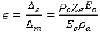
Figure 4 is obtained by following the second method for gold nanoparticles of 100nm with a nominal diameter. 174 absorptions of said nanoparticles were measured on the surface of a cantilever. Frequency changes in the first 3 flexural modes were stored and the second method described above was used to extract the mass, position and rigidity of the gold nanoparticles. A graph of the mass (figure 4 ) and another for ε) (figure 5 ) was prepared using this data. The graph of the mass also shows the distribution provided by the manufacturer (Sigma Aldrich, segment with continuous line) and the distribution of the mass obtained without taking into account the rigidity (method described in the state of the art) where a displacement in the distribution of the mass towards smaller values when rigidity is not taken into account may be clearly seen. The graph also shows that the data that include the rigidity effect fit better with the distribution of the mass provided by the manufacturer, such that the method of the invention presents the additional advantage of improving the measurements of the mass parameter. - Based on the definitions provided above for Δ m and Δ s , the parameter ε may be expressed as:
Claims (5)
- A method for obtaining the absorption position, mass and rigidity of a particle deposited on the surface of a resonator based on the relative change in the resonance frequency of said resonator in 3 or 4 flexural vibration modes, where said method comprises the following steps:a. the standard deviation of the relative frequency change of each mode σn and the values of the relative frequency change corresponding to adsorption µn is calculated,b. the following probability density function is formed


M = (µ 1,µ 2,...,µN ) and Σ is the covariance matrix given by: c. the values of ξ0, Δm and Δs that maximise the probability density function are calculated.
 - The method according to claim 1, wherein the resonator is a cantilever or a bridge.
- The method according to any of claims 1 or 2, wherein, in order to maximise the probability density function JPDF(Ω̂), the following functional is minimised:

- The method according to any of claims 1 or 2, wherein, in order to maximise the probability density function JPDF(Ω̂), the following functional is formed:



the following functional is formed:
the value of Δ m that minimises the functional F is found. - The method according to any of the preceding claims wherein the particles are inorganic, virus, bacteria, protein or cell particles.
Applications Claiming Priority (2)
| Application Number | Priority Date | Filing Date | Title |
|---|---|---|---|
| ES201630443A ES2642640B1 (en) | 2016-04-11 | 2016-04-11 | Procedure to obtain the adsorption position, mass and stiffness of a particle |
| PCT/ES2017/070098 WO2017178672A1 (en) | 2016-04-11 | 2017-02-22 | Method for obtaining the absorption position, mass and rigidity of a particle |
Publications (2)
| Publication Number | Publication Date |
|---|---|
| EP3444837A1 true EP3444837A1 (en) | 2019-02-20 |
| EP3444837B1 EP3444837B1 (en) | 2019-08-28 |
Family
ID=58267135
Family Applications (1)
| Application Number | Title | Priority Date | Filing Date |
|---|---|---|---|
| EP17710586.3A Active EP3444837B1 (en) | 2016-04-11 | 2017-02-22 | Method for obtaining the absorption position, mass and rigidity of a particle deposited on the surface of a resonator |
Country Status (4)
| Country | Link |
|---|---|
| US (1) | US10670447B2 (en) |
| EP (1) | EP3444837B1 (en) |
| ES (2) | ES2642640B1 (en) |
| WO (1) | WO2017178672A1 (en) |
Families Citing this family (1)
| Publication number | Priority date | Publication date | Assignee | Title |
|---|---|---|---|---|
| ES2776702B2 (en) * | 2019-01-31 | 2020-12-22 | Consejo Superior Investigacion | METHOD AND SYSTEM FOR THE IDENTIFICATION OF PARTICLES BASED ON MULTIFREQUENCY MEASUREMENTS OF RESONANT PLATES |
Family Cites Families (5)
| Publication number | Priority date | Publication date | Assignee | Title |
|---|---|---|---|---|
| JP2004028956A (en) * | 2002-06-28 | 2004-01-29 | National Institute Of Advanced Industrial & Technology | Adsorption / desorption measurement method and device |
| KR100552696B1 (en) * | 2003-11-12 | 2006-02-20 | 삼성전자주식회사 | Apparatus and method for fine mass measurement with oscillation circuit |
| US8507845B2 (en) * | 2011-06-02 | 2013-08-13 | Wisconsin Alumni Research Foundation | Membrane detector for time-of-flight mass spectrometry |
| US9347815B2 (en) * | 2012-05-09 | 2016-05-24 | California Institute Of Technology | Single-protein nanomechanical mass spectrometry in real time |
| WO2014130095A2 (en) * | 2013-02-22 | 2014-08-28 | California Institute Of Technology | Shape analysis and mass spectrometry of individual molecules by nanomechanical systems |
-
2016
- 2016-04-11 ES ES201630443A patent/ES2642640B1/en not_active Expired - Fee Related
-
2017
- 2017-02-22 EP EP17710586.3A patent/EP3444837B1/en active Active
- 2017-02-22 WO PCT/ES2017/070098 patent/WO2017178672A1/en not_active Ceased
- 2017-02-22 ES ES17710586T patent/ES2748291T3/en active Active
- 2017-02-22 US US16/093,088 patent/US10670447B2/en active Active
Also Published As
| Publication number | Publication date |
|---|---|
| ES2642640R1 (en) | 2018-01-04 |
| ES2642640B1 (en) | 2018-10-26 |
| EP3444837B1 (en) | 2019-08-28 |
| WO2017178672A1 (en) | 2017-10-19 |
| US20190162580A1 (en) | 2019-05-30 |
| US10670447B2 (en) | 2020-06-02 |
| ES2642640A2 (en) | 2017-11-17 |
| ES2748291T3 (en) | 2020-03-16 |
Similar Documents
| Publication | Publication Date | Title |
|---|---|---|
| US9347815B2 (en) | Single-protein nanomechanical mass spectrometry in real time | |
| US6906322B2 (en) | Charged particle source with droplet control for mass spectrometry | |
| US8716654B2 (en) | Electrostatic trap | |
| US6124592A (en) | Ion mobility storage trap and method | |
| US7928375B1 (en) | Microfabricated linear Paul-Straubel ion trap | |
| EP4022282B1 (en) | Photoacoustic gas sensor, manufacturing method and gas analysis | |
| US9058968B2 (en) | Micro-reflectron for time-of-flight mass spectrometer | |
| EP3931558B1 (en) | Photoacoustic spectroscope with a vibrating structure as sound detector | |
| EP2927666A1 (en) | Particle beam forming device | |
| EP2126961B1 (en) | Method to accurately discriminate gas phase ions with several filtering devices in tandem | |
| JPH08273588A (en) | Ion trap mass spectrometry method and device | |
| EP3919890B1 (en) | Photoacoustic spectroscopy of gas mixtures by means of tunable fabry-pérot interferometer | |
| EP3444837B1 (en) | Method for obtaining the absorption position, mass and rigidity of a particle deposited on the surface of a resonator | |
| Liu et al. | Rydberg electron transfer to SF6: Product ion lifetimes | |
| Lei et al. | Analysis of atmospheric particles: From the bulk to the interface | |
| Hrabovsky et al. | Charge Detection Mass Spectrometry for Megadalton Polymer Characterization and Measurement of Electrospray-Generated Charged Droplet Dynamics with a New “Direct Visualization of the Rayleigh Limit” Approach to Aid in m/z Calibration | |
| WO2024009203A1 (en) | Device and method for the determination of the size and electric charge distribution of an ensemble of particles | |
| Regord et al. | Real-Time Monitoring of Analyte Mass Dynamics with Nems-Based Mass Spectrometry | |
| Challamalla et al. | Negative ion mode mass spectrometry-an overview | |
| US10685827B2 (en) | Quadrupole ion trap apparatus and quadrupole mass spectrometer | |
| Carette et al. | Probing radial and axial secular frequencies in a quadrupole ion trap | |
| US8258464B2 (en) | Mass spectrometer and methods for detecting large biomolecules | |
| Djera et al. | Associative ionisation in Rb (nL)-K (4S) collisions | |
| Gustafson | Charge Detection Mass Spectrometry Using Printed Circuit Board Arrays for the Analysis of Microparticles in the Martian Atmosphere | |
| Tang et al. | Ion pair production in Li-Cs collisions |
Legal Events
| Date | Code | Title | Description |
|---|---|---|---|
| STAA | Information on the status of an ep patent application or granted ep patent |
Free format text: STATUS: UNKNOWN |
|
| STAA | Information on the status of an ep patent application or granted ep patent |
Free format text: STATUS: THE INTERNATIONAL PUBLICATION HAS BEEN MADE |
|
| PUAI | Public reference made under article 153(3) epc to a published international application that has entered the european phase |
Free format text: ORIGINAL CODE: 0009012 |
|
| STAA | Information on the status of an ep patent application or granted ep patent |
Free format text: STATUS: REQUEST FOR EXAMINATION WAS MADE |
|
| 17P | Request for examination filed |
Effective date: 20181009 |
|
| AK | Designated contracting states |
Kind code of ref document: A1 Designated state(s): AL AT BE BG CH CY CZ DE DK EE ES FI FR GB GR HR HU IE IS IT LI LT LU LV MC MK MT NL NO PL PT RO RS SE SI SK SM TR |
|
| AX | Request for extension of the european patent |
Extension state: BA ME |
|
| GRAP | Despatch of communication of intention to grant a patent |
Free format text: ORIGINAL CODE: EPIDOSNIGR1 |
|
| RIC1 | Information provided on ipc code assigned before grant |
Ipc: H01J 49/26 20060101AFI20190522BHEP Ipc: G01N 15/10 20060101ALI20190522BHEP |
|
| DAV | Request for validation of the european patent (deleted) | ||
| DAX | Request for extension of the european patent (deleted) | ||
| INTG | Intention to grant announced |
Effective date: 20190614 |
|
| STAA | Information on the status of an ep patent application or granted ep patent |
Free format text: STATUS: GRANT OF PATENT IS INTENDED |
|
| GRAS | Grant fee paid |
Free format text: ORIGINAL CODE: EPIDOSNIGR3 |
|
| GRAA | (expected) grant |
Free format text: ORIGINAL CODE: 0009210 |
|
| STAA | Information on the status of an ep patent application or granted ep patent |
Free format text: STATUS: THE PATENT HAS BEEN GRANTED |
|
| AK | Designated contracting states |
Kind code of ref document: B1 Designated state(s): AL AT BE BG CH CY CZ DE DK EE ES FI FR GB GR HR HU IE IS IT LI LT LU LV MC MK MT NL NO PL PT RO RS SE SI SK SM TR |
|
| REG | Reference to a national code |
Ref country code: GB Ref legal event code: FG4D |
|
| REG | Reference to a national code |
Ref country code: CH Ref legal event code: EP |
|
| REG | Reference to a national code |
Ref country code: AT Ref legal event code: REF Ref document number: 1173441 Country of ref document: AT Kind code of ref document: T Effective date: 20190915 |
|
| REG | Reference to a national code |
Ref country code: IE Ref legal event code: FG4D |
|
| REG | Reference to a national code |
Ref country code: DE Ref legal event code: R096 Ref document number: 602017006576 Country of ref document: DE |
|
| REG | Reference to a national code |
Ref country code: NL Ref legal event code: MP Effective date: 20190828 |
|
| REG | Reference to a national code |
Ref country code: LT Ref legal event code: MG4D |
|
| PG25 | Lapsed in a contracting state [announced via postgrant information from national office to epo] |
Ref country code: NO Free format text: LAPSE BECAUSE OF FAILURE TO SUBMIT A TRANSLATION OF THE DESCRIPTION OR TO PAY THE FEE WITHIN THE PRESCRIBED TIME-LIMIT Effective date: 20191128 Ref country code: SE Free format text: LAPSE BECAUSE OF FAILURE TO SUBMIT A TRANSLATION OF THE DESCRIPTION OR TO PAY THE FEE WITHIN THE PRESCRIBED TIME-LIMIT Effective date: 20190828 Ref country code: NL Free format text: LAPSE BECAUSE OF FAILURE TO SUBMIT A TRANSLATION OF THE DESCRIPTION OR TO PAY THE FEE WITHIN THE PRESCRIBED TIME-LIMIT Effective date: 20190828 Ref country code: BG Free format text: LAPSE BECAUSE OF FAILURE TO SUBMIT A TRANSLATION OF THE DESCRIPTION OR TO PAY THE FEE WITHIN THE PRESCRIBED TIME-LIMIT Effective date: 20191128 Ref country code: LT Free format text: LAPSE BECAUSE OF FAILURE TO SUBMIT A TRANSLATION OF THE DESCRIPTION OR TO PAY THE FEE WITHIN THE PRESCRIBED TIME-LIMIT Effective date: 20190828 Ref country code: HR Free format text: LAPSE BECAUSE OF FAILURE TO SUBMIT A TRANSLATION OF THE DESCRIPTION OR TO PAY THE FEE WITHIN THE PRESCRIBED TIME-LIMIT Effective date: 20190828 Ref country code: FI Free format text: LAPSE BECAUSE OF FAILURE TO SUBMIT A TRANSLATION OF THE DESCRIPTION OR TO PAY THE FEE WITHIN THE PRESCRIBED TIME-LIMIT Effective date: 20190828 Ref country code: PT Free format text: LAPSE BECAUSE OF FAILURE TO SUBMIT A TRANSLATION OF THE DESCRIPTION OR TO PAY THE FEE WITHIN THE PRESCRIBED TIME-LIMIT Effective date: 20191230 |
|
| PG25 | Lapsed in a contracting state [announced via postgrant information from national office to epo] |
Ref country code: GR Free format text: LAPSE BECAUSE OF FAILURE TO SUBMIT A TRANSLATION OF THE DESCRIPTION OR TO PAY THE FEE WITHIN THE PRESCRIBED TIME-LIMIT Effective date: 20191129 Ref country code: AL Free format text: LAPSE BECAUSE OF FAILURE TO SUBMIT A TRANSLATION OF THE DESCRIPTION OR TO PAY THE FEE WITHIN THE PRESCRIBED TIME-LIMIT Effective date: 20190828 Ref country code: LV Free format text: LAPSE BECAUSE OF FAILURE TO SUBMIT A TRANSLATION OF THE DESCRIPTION OR TO PAY THE FEE WITHIN THE PRESCRIBED TIME-LIMIT Effective date: 20190828 Ref country code: RS Free format text: LAPSE BECAUSE OF FAILURE TO SUBMIT A TRANSLATION OF THE DESCRIPTION OR TO PAY THE FEE WITHIN THE PRESCRIBED TIME-LIMIT Effective date: 20190828 Ref country code: IS Free format text: LAPSE BECAUSE OF FAILURE TO SUBMIT A TRANSLATION OF THE DESCRIPTION OR TO PAY THE FEE WITHIN THE PRESCRIBED TIME-LIMIT Effective date: 20191228 |
|
| REG | Reference to a national code |
Ref country code: AT Ref legal event code: MK05 Ref document number: 1173441 Country of ref document: AT Kind code of ref document: T Effective date: 20190828 |
|
| REG | Reference to a national code |
Ref country code: ES Ref legal event code: FG2A Ref document number: 2748291 Country of ref document: ES Kind code of ref document: T3 Effective date: 20200316 |
|
| PG25 | Lapsed in a contracting state [announced via postgrant information from national office to epo] |
Ref country code: TR Free format text: LAPSE BECAUSE OF FAILURE TO SUBMIT A TRANSLATION OF THE DESCRIPTION OR TO PAY THE FEE WITHIN THE PRESCRIBED TIME-LIMIT Effective date: 20190828 |
|
| PG25 | Lapsed in a contracting state [announced via postgrant information from national office to epo] |
Ref country code: AT Free format text: LAPSE BECAUSE OF FAILURE TO SUBMIT A TRANSLATION OF THE DESCRIPTION OR TO PAY THE FEE WITHIN THE PRESCRIBED TIME-LIMIT Effective date: 20190828 Ref country code: RO Free format text: LAPSE BECAUSE OF FAILURE TO SUBMIT A TRANSLATION OF THE DESCRIPTION OR TO PAY THE FEE WITHIN THE PRESCRIBED TIME-LIMIT Effective date: 20190828 Ref country code: PL Free format text: LAPSE BECAUSE OF FAILURE TO SUBMIT A TRANSLATION OF THE DESCRIPTION OR TO PAY THE FEE WITHIN THE PRESCRIBED TIME-LIMIT Effective date: 20190828 Ref country code: EE Free format text: LAPSE BECAUSE OF FAILURE TO SUBMIT A TRANSLATION OF THE DESCRIPTION OR TO PAY THE FEE WITHIN THE PRESCRIBED TIME-LIMIT Effective date: 20190828 Ref country code: DK Free format text: LAPSE BECAUSE OF FAILURE TO SUBMIT A TRANSLATION OF THE DESCRIPTION OR TO PAY THE FEE WITHIN THE PRESCRIBED TIME-LIMIT Effective date: 20190828 |
|
| PG25 | Lapsed in a contracting state [announced via postgrant information from national office to epo] |
Ref country code: SM Free format text: LAPSE BECAUSE OF FAILURE TO SUBMIT A TRANSLATION OF THE DESCRIPTION OR TO PAY THE FEE WITHIN THE PRESCRIBED TIME-LIMIT Effective date: 20190828 Ref country code: IS Free format text: LAPSE BECAUSE OF FAILURE TO SUBMIT A TRANSLATION OF THE DESCRIPTION OR TO PAY THE FEE WITHIN THE PRESCRIBED TIME-LIMIT Effective date: 20200224 Ref country code: SK Free format text: LAPSE BECAUSE OF FAILURE TO SUBMIT A TRANSLATION OF THE DESCRIPTION OR TO PAY THE FEE WITHIN THE PRESCRIBED TIME-LIMIT Effective date: 20190828 Ref country code: CZ Free format text: LAPSE BECAUSE OF FAILURE TO SUBMIT A TRANSLATION OF THE DESCRIPTION OR TO PAY THE FEE WITHIN THE PRESCRIBED TIME-LIMIT Effective date: 20190828 |
|
| REG | Reference to a national code |
Ref country code: DE Ref legal event code: R097 Ref document number: 602017006576 Country of ref document: DE |
|
| PLBE | No opposition filed within time limit |
Free format text: ORIGINAL CODE: 0009261 |
|
| STAA | Information on the status of an ep patent application or granted ep patent |
Free format text: STATUS: NO OPPOSITION FILED WITHIN TIME LIMIT |
|
| PG2D | Information on lapse in contracting state deleted |
Ref country code: IS |
|
| 26N | No opposition filed |
Effective date: 20200603 |
|
| REG | Reference to a national code |
Ref country code: CH Ref legal event code: PL |
|
| REG | Reference to a national code |
Ref country code: BE Ref legal event code: MM Effective date: 20200229 |
|
| PG25 | Lapsed in a contracting state [announced via postgrant information from national office to epo] |
Ref country code: MC Free format text: LAPSE BECAUSE OF FAILURE TO SUBMIT A TRANSLATION OF THE DESCRIPTION OR TO PAY THE FEE WITHIN THE PRESCRIBED TIME-LIMIT Effective date: 20190828 Ref country code: LU Free format text: LAPSE BECAUSE OF NON-PAYMENT OF DUE FEES Effective date: 20200222 |
|
| PG25 | Lapsed in a contracting state [announced via postgrant information from national office to epo] |
Ref country code: CH Free format text: LAPSE BECAUSE OF NON-PAYMENT OF DUE FEES Effective date: 20200229 Ref country code: LI Free format text: LAPSE BECAUSE OF NON-PAYMENT OF DUE FEES Effective date: 20200229 |
|
| PG25 | Lapsed in a contracting state [announced via postgrant information from national office to epo] |
Ref country code: IE Free format text: LAPSE BECAUSE OF NON-PAYMENT OF DUE FEES Effective date: 20200222 |
|
| PG25 | Lapsed in a contracting state [announced via postgrant information from national office to epo] |
Ref country code: BE Free format text: LAPSE BECAUSE OF NON-PAYMENT OF DUE FEES Effective date: 20200229 |
|
| PG25 | Lapsed in a contracting state [announced via postgrant information from national office to epo] |
Ref country code: MT Free format text: LAPSE BECAUSE OF FAILURE TO SUBMIT A TRANSLATION OF THE DESCRIPTION OR TO PAY THE FEE WITHIN THE PRESCRIBED TIME-LIMIT Effective date: 20190828 Ref country code: CY Free format text: LAPSE BECAUSE OF FAILURE TO SUBMIT A TRANSLATION OF THE DESCRIPTION OR TO PAY THE FEE WITHIN THE PRESCRIBED TIME-LIMIT Effective date: 20190828 |
|
| PG25 | Lapsed in a contracting state [announced via postgrant information from national office to epo] |
Ref country code: MK Free format text: LAPSE BECAUSE OF FAILURE TO SUBMIT A TRANSLATION OF THE DESCRIPTION OR TO PAY THE FEE WITHIN THE PRESCRIBED TIME-LIMIT Effective date: 20190828 |
|
| GRAP | Despatch of communication of intention to grant a patent |
Free format text: ORIGINAL CODE: EPIDOSNIGR1 |
|
| REG | Reference to a national code |
Ref country code: GB Ref legal event code: 732E Free format text: REGISTERED BETWEEN 20230608 AND 20230614 |
|
| PG25 | Lapsed in a contracting state [announced via postgrant information from national office to epo] |
Ref country code: SI Free format text: LAPSE BECAUSE OF FAILURE TO SUBMIT A TRANSLATION OF THE DESCRIPTION OR TO PAY THE FEE WITHIN THE PRESCRIBED TIME-LIMIT Effective date: 20190828 |
|
| REG | Reference to a national code |
Ref country code: ES Ref legal event code: PC2A Owner name: CONSEJO SUPERIOR DE INVESTIGACIONES CIENTIFICAS Effective date: 20240314 |
|
| PGFP | Annual fee paid to national office [announced via postgrant information from national office to epo] |
Ref country code: ES Payment date: 20240305 Year of fee payment: 8 |
|
| PGFP | Annual fee paid to national office [announced via postgrant information from national office to epo] |
Ref country code: DE Payment date: 20240228 Year of fee payment: 8 Ref country code: GB Payment date: 20240227 Year of fee payment: 8 |
|
| PGFP | Annual fee paid to national office [announced via postgrant information from national office to epo] |
Ref country code: IT Payment date: 20240222 Year of fee payment: 8 Ref country code: FR Payment date: 20240226 Year of fee payment: 8 |
|
| REG | Reference to a national code |
Ref country code: DE Ref legal event code: R119 Ref document number: 602017006576 Country of ref document: DE |
|
| GBPC | Gb: european patent ceased through non-payment of renewal fee |
Effective date: 20250222 |
|
| PG25 | Lapsed in a contracting state [announced via postgrant information from national office to epo] |
Ref country code: DE Free format text: LAPSE BECAUSE OF NON-PAYMENT OF DUE FEES Effective date: 20250902 |
|
| PG25 | Lapsed in a contracting state [announced via postgrant information from national office to epo] |
Ref country code: GB Free format text: LAPSE BECAUSE OF NON-PAYMENT OF DUE FEES Effective date: 20250222 |
|
| PG25 | Lapsed in a contracting state [announced via postgrant information from national office to epo] |
Ref country code: IT Free format text: LAPSE BECAUSE OF NON-PAYMENT OF DUE FEES Effective date: 20250222 Ref country code: FR Free format text: LAPSE BECAUSE OF NON-PAYMENT OF DUE FEES Effective date: 20250228 |
|
| REG | Reference to a national code |
Ref country code: ES Ref legal event code: FD2A Effective date: 20260406 |
|
| PG25 | Lapsed in a contracting state [announced via postgrant information from national office to epo] |
Ref country code: ES Free format text: LAPSE BECAUSE OF NON-PAYMENT OF DUE FEES Effective date: 20250223 |