EP3444831A1 - Vacuum circuit breaker and gas-insulated switchgear and air-insulated switchgear having integrated vacuum circuit breaker - Google Patents
Vacuum circuit breaker and gas-insulated switchgear and air-insulated switchgear having integrated vacuum circuit breaker Download PDFInfo
- Publication number
- EP3444831A1 EP3444831A1 EP17782133.7A EP17782133A EP3444831A1 EP 3444831 A1 EP3444831 A1 EP 3444831A1 EP 17782133 A EP17782133 A EP 17782133A EP 3444831 A1 EP3444831 A1 EP 3444831A1
- Authority
- EP
- European Patent Office
- Prior art keywords
- circuit breaker
- movable side
- vacuum circuit
- shaft
- energization
- Prior art date
- Legal status (The legal status is an assumption and is not a legal conclusion. Google has not performed a legal analysis and makes no representation as to the accuracy of the status listed.)
- Granted
Links
Images


Classifications
-
- H—ELECTRICITY
- H01—ELECTRIC ELEMENTS
- H01H—ELECTRIC SWITCHES; RELAYS; SELECTORS; EMERGENCY PROTECTIVE DEVICES
- H01H33/00—High-tension or heavy-current switches with arc-extinguishing or arc-preventing means
- H01H33/60—Switches wherein the means for extinguishing or preventing the arc do not include separate means for obtaining or increasing flow of arc-extinguishing fluid
- H01H33/66—Vacuum switches
- H01H33/6606—Terminal arrangements
-
- H—ELECTRICITY
- H01—ELECTRIC ELEMENTS
- H01H—ELECTRIC SWITCHES; RELAYS; SELECTORS; EMERGENCY PROTECTIVE DEVICES
- H01H33/00—High-tension or heavy-current switches with arc-extinguishing or arc-preventing means
- H01H33/02—Details
- H01H33/42—Driving mechanisms
-
- H—ELECTRICITY
- H01—ELECTRIC ELEMENTS
- H01H—ELECTRIC SWITCHES; RELAYS; SELECTORS; EMERGENCY PROTECTIVE DEVICES
- H01H33/00—High-tension or heavy-current switches with arc-extinguishing or arc-preventing means
- H01H33/60—Switches wherein the means for extinguishing or preventing the arc do not include separate means for obtaining or increasing flow of arc-extinguishing fluid
- H01H33/66—Vacuum switches
- H01H33/662—Housings or protective screens
- H01H33/66207—Specific housing details, e.g. sealing, soldering or brazing
-
- H—ELECTRICITY
- H01—ELECTRIC ELEMENTS
- H01H—ELECTRIC SWITCHES; RELAYS; SELECTORS; EMERGENCY PROTECTIVE DEVICES
- H01H33/00—High-tension or heavy-current switches with arc-extinguishing or arc-preventing means
- H01H33/60—Switches wherein the means for extinguishing or preventing the arc do not include separate means for obtaining or increasing flow of arc-extinguishing fluid
- H01H33/66—Vacuum switches
- H01H33/666—Operating arrangements
-
- H—ELECTRICITY
- H01—ELECTRIC ELEMENTS
- H01H—ELECTRIC SWITCHES; RELAYS; SELECTORS; EMERGENCY PROTECTIVE DEVICES
- H01H1/00—Contacts
- H01H1/58—Electric connections to or between contacts; Terminals
- H01H1/5822—Flexible connections between movable contact and terminal
-
- H—ELECTRICITY
- H01—ELECTRIC ELEMENTS
- H01H—ELECTRIC SWITCHES; RELAYS; SELECTORS; EMERGENCY PROTECTIVE DEVICES
- H01H33/00—High-tension or heavy-current switches with arc-extinguishing or arc-preventing means
- H01H33/02—Details
- H01H33/42—Driving mechanisms
- H01H2033/426—Details concerning the connection of the isolating driving rod to a metallic part
-
- H—ELECTRICITY
- H01—ELECTRIC ELEMENTS
- H01H—ELECTRIC SWITCHES; RELAYS; SELECTORS; EMERGENCY PROTECTIVE DEVICES
- H01H33/00—High-tension or heavy-current switches with arc-extinguishing or arc-preventing means
- H01H33/60—Switches wherein the means for extinguishing or preventing the arc do not include separate means for obtaining or increasing flow of arc-extinguishing fluid
- H01H33/66—Vacuum switches
- H01H33/662—Housings or protective screens
- H01H33/66238—Specific bellows details
-
- H—ELECTRICITY
- H01—ELECTRIC ELEMENTS
- H01H—ELECTRIC SWITCHES; RELAYS; SELECTORS; EMERGENCY PROTECTIVE DEVICES
- H01H33/00—High-tension or heavy-current switches with arc-extinguishing or arc-preventing means
- H01H33/60—Switches wherein the means for extinguishing or preventing the arc do not include separate means for obtaining or increasing flow of arc-extinguishing fluid
- H01H33/66—Vacuum switches
- H01H33/662—Housings or protective screens
- H01H33/66261—Specific screen details, e.g. mounting, materials, multiple screens or specific electrical field considerations
-
- H—ELECTRICITY
- H02—GENERATION; CONVERSION OR DISTRIBUTION OF ELECTRIC POWER
- H02B—BOARDS, SUBSTATIONS OR SWITCHING ARRANGEMENTS FOR THE SUPPLY OR DISTRIBUTION OF ELECTRIC POWER
- H02B13/00—Arrangement of switchgear in which switches are enclosed in, or structurally associated with, a casing, e.g. cubicle
- H02B13/02—Arrangement of switchgear in which switches are enclosed in, or structurally associated with, a casing, e.g. cubicle with metal casing
- H02B13/035—Gas-insulated switchgear
- H02B13/0354—Gas-insulated switchgear comprising a vacuum switch
Definitions
- the present invention relates to, for example, a vacuum circuit breaker that improves energization performance of a vacuum valve, and a gas insulated switchgear and an air insulated switchgear which are mounted with the vacuum circuit breaker.
- a vacuum circuit breaker compactifies the circuit breaker by using a vacuum valve that utilizes superior arc extinguishing performance and insulation performance in a vacuum. It is said that the vacuum circuit breaker is more superior in interruption performance and insulation performance than a gas circuit breaker; however, as for energization performance, the vacuum circuit breaker is more inferior than the gas circuit breaker.
- a movable shaft and a fixed shaft of the vacuum valve are made thick to reduce electrical resistance thereof and improve heat conductivity.
- the movable shaft and the fixed shaft of the vacuum valve are made thick to reduce the electrical resistance thereof and improve the heat conductivity.
- the movable shaft of the vacuum valve is made thick, the weight of a movable portion increases and accordingly large operational energy is required due to an operating mechanism of the vacuum circuit breaker.
- Patent Document 1 as shown in FIG. 1 of JP-A-2006-324 177 , a part where the movable shaft of the vacuum valve protrudes to the outside from the vacuum valve is made thicker in diameter than the movable shaft that communicates to the inside of the vacuum valve to improve the heat conductivity.
- the movable shaft of the thick diameter and that of a thin diameter are integrated into one body, it becomes a structure that cannot be assembled if a guide that mechanically supports the thin diameter part of the movable shaft is not divided into plurality; and accordingly, axial misalignment of the movable shaft is likely to be increased.
- the structure is such that tapping/threading is made at the tip of the thick diameter portion of the movable shaft to couple an operating shaft which is for opening and closing the vacuum valve.
- the thick diameter portion and the thin diameter portion of the movable shaft are each formed in a columnar shape and accordingly there is not a portion that prevents the movable shaft from pivoting during screw fastening.
- Patent Document 2 as shown in FIG. 1 of JP-A-2009-009 849 , a heat dissipation fin is mounted around a terminal that slides and comes into contact with the movable shaft of the vacuum valve to improve heat dissipation performance.
- the heated movable shaft only comes into contact with the terminal itself by a sliding contactor; and accordingly, a problem exists in that heat conductivity from the movable shaft to the terminal is bad and thus the heat dissipation performance from the terminal is not sufficiently exerted, either.
- the present invention has been made to solve the problem described above, and an object of the present invention is to provide a vacuum circuit breaker capable of efficiently dissipating heat generated in a vacuum valve.
- a vacuum circuit breaker including: a movable side contact and a fixed side contact which are arranged in the inside of a vacuum valve; a fixed side energization shaft to which the fixed side contact is fixed; a movable side energization shaft to which the movable side contact is fixed; an energization connection portion provided at a position where the movable side energization shaft protrudes from the vacuum valve; and a coupling body provided at the outside tip portion of the movable side energization shaft.
- the coupling body at the outside tip portion of the movable side energization shaft is coupled to an insulation operating rod.
- the vacuum circuit breaker capable of efficiently dissipating heat generated in the vacuum valve.
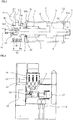
- FIG. 1 is a sectional view showing a main circuit in a vacuum circuit breaker according to Embodiment 1 of the present invention.
- FIG. 2 is a sectional view showing a switchgear mounted with the vacuum circuit breaker according to Embodiment 1 of the present invention.
- FIG. 3 is a sectional view showing a vacuum valve in the vacuum circuit breaker according to Embodiment 1 of the present invention.
- FIG. 4 is a perspective view showing the vacuum valve in the vacuum circuit breaker according to Embodiment 1 of the present invention.
- FIG. 5 is a front view showing the guide portion of a movable shaft of the vacuum valve in the vacuum circuit breaker according to Embodiment 1 of the present invention.
- FIG. 6 is a side view showing a split terminal in the vacuum circuit breaker according to Embodiment 1 of the present invention.
- FIG. 7 is a front view showing the split terminal in the vacuum circuit breaker according to Embodiment 1 of the present invention.
- FIG. 1 and FIG. 2 current energized from a cable 16 in the switchgear is energized by paths of an instrument current transformer 17, a vacuum circuit breaker 12, a disconnecting switch 14, and a bus 18.
- an instrument current transformer 17 a vacuum circuit breaker 12
- a disconnecting switch 14 a disconnecting switch 14
- a bus 18 a bus 18.
- this embodiment can be applicable to not only the vacuum circuit breaker for the gas insulated switchgear, but also the vacuum circuit breaker to be mounted on an air insulated switchgear that is used in the air. Furthermore, the vacuum circuit breaker 12 is operated by an operating mechanism 13 of the vacuum circuit breaker 12; and the disconnecting switch 14 is operated by an operating mechanism 15 of the disconnecting switch 14.
- the vacuum valve 1 is configured by a cylindrical insulation tube that uses an insulator such as alumina ceramic as a material; and a fixed side flange 1a and a movable side flange 1b which use metal such as stainless steel as a material are mounted on both end sides of the vacuum valve 1 to form a container so that the inside thereof is kept high vacuum and airtight.
- a pair of a movable side contact 2 and a fixed side contact 3 which are supported to be capable of being connected/disconnected by a movable side energization shaft 5 and a fixed side energization shaft 6 are arranged in the inside of the vacuum valve 1; and the fixed side contact 3 is connected to the fixed side terminal 7 outside the vacuum valve 1 via the fixed side energization shaft 6 fixed to the fixed side flange 1a.
- reference numeral 21a denotes a metallic thin sheet disk-shaped fixed side electric field relaxation shield and is retained in a manner being sandwiched between the fixed side energization shaft 6 and the fixed side terminal 7.
- reference numeral 21b denotes a metallic thin sheet disk-shaped movable side electric field relaxation shield and is retained in a manner being sandwiched between a guide 8 (to be described later) and an attaching seat 22 when the guide 8 is screwed to the attaching seat 22 attached to the end surface of the movable side flange 1b.
- the movable side contact 2 is linked to the movable side energization shaft 5 which is inserted through the movable side flange 1b and is extended to the outside.
- the movable side energization shaft 5 is formed in a polygonal shape such as a hexagon bar; and an energization connection portion 50 is provided at a position where the movable side energization shaft 5 of the hexagon bar protrudes to the outside of the vacuum valve 1.
- the energization connection portion 50 includes: an energization contact surface 5a that is formed, for example, in a columnar shape on the outer periphery of, for example, the movable side energization shaft 5 of the hexagon bar; and a split terminal 9 that is to be connected to the energization contact surface 5a.
- the split terminal 9 is coupled to a flexible conductor 11 to be connected to a movable side terminal.
- a bellows 4 is brazed to the movable side energization shaft 5, thereby enabling it to advance and retract the movable side energization shaft 5 in closing and opening directions while the inside of the vacuum valve 1 is kept vacuum.
- a structure is such that the guide 8 of the movable side energization shaft 5 is placed on the movable side flange 1b at a portion where the movable side energization shaft 5 protrudes to the outside of the vacuum valve 1 to prevent axial misalignment in the case of advancing and retracting the movable side energization shaft 5 in the closing and opening directions.
- the flexible conductor 11 is connected to the split terminal 9, thereby enabling it to advance and retract the movable side energization shaft 5 in the closing and opening directions while securing an energization path of the movable side energization shaft 5.
- an insulation operating rod 10 of the vacuum circuit breaker 12 is coupled to the tip of the movable side energization shaft 5; and the insulation operating rod 10 is coupled to the operating mechanism 13 of the vacuum circuit breaker 12, thereby enabling it to operate the vacuum circuit breaker 12 in a state where electrical insulation between the operating mechanism 13 of the vacuum circuit breaker 12 and the vacuum valve 1 is maintained.
- the movable side energization shaft 5 of the vacuum valve 1 is formed by, for example, the hexagon bar of copper or copper alloy as shown in FIG. 3 and FIG. 4 . Furthermore, a structure is such that the guide 8 of the movable side energization shaft 5 shown in FIG. 5 is formed with an insertion hole 8a formed, for example, in a hexagon shape, through which the movable side energization shaft 5 formed by the hexagon bar inserts, to support the movable side energization shaft 5 of the hexagon bar.
- the movable side energization shaft 5 is formed by the hexagon bar and the guide 8 is formed with the insertion hole 8a of the hexagon shape, whereby the guide 8 not only supports the movable side energization shaft 5 to prevent the axial misalignment when the movable side energization shaft 5 advances and retracts in the closing and opening directions, but also prevents the movable side energization shaft 5 from rotating during assembly.
- the movable side energization shaft 5 is connected to the bellows 4 of the vacuum valve 1; and accordingly, the bellows 4 is twisted when the movable side energization shaft 5 rotates and vacuum airtightness that is the most important performance of the vacuum valve 1 is likely to be reduced.
- the guide 8 of the movable side energization shaft 5 is made of a thermosetting or thermoplastic insulator and thus rotation during the advance and retraction of the movable side energization shaft 5 in the closing and opening directions can be prevented; however, when large torque at the time of fastening the movable side energization shaft 5 to the insulation operating rod 10 is supported, the guide 8 is likely to be split if the torque is supported by only the guide 8; and therefore, the structure is such that the wrench catcher portion 5b of the movable side energization shaft 5 is supported by a tool such as a wrench in fastening to the insulation operating rod 10.
- a hole 5b1 is formed in the inside of the wrench catcher portion 5b positioned at the tip part of the movable side energization shaft 5; a coupling body 19 made of, for example, a female screw rod is inserted into the hole 5b1 formed in the wrench catcher portion 5b of the movable side energization shaft 5; and the movable side energization shaft 5 and the coupling body 19 made of the female screw rod are bonded by, for example, blazing.
- Screw fastening is used in fastening to the insulation operating rod 10; however, when tapping/threading is made in the movable side energization shaft 5 made of copper or copper alloy, the copper or copper alloy is low in mechanical strength and thus it cannot endure against large fastening torque. Accordingly, screw threads are stripped; and when the vacuum valve 1 is opened and closed a large number of times, the screw threads are stripped and fastening between the insulation operating rod 10 and the movable side energization shaft 5 is likely to be unfastened.
- the coupling body 19 made of the female screw rod is blazed to the wrench catcher portion 5b that is the tip of the movable side energization shaft 5; however, it similarly functions even a male screw but not the female screw.
- the split terminal 9 is a pair of two terminals of a right side split terminal 9a and a left side split terminal 9b; and a part that is formed in a circular shape at a center portion serves as a connection portion 9c of the split terminal 9 with the movable side energization shaft 5.
- the connection portion 9c of the split terminal 9 is connected to the energization contact surface 5a of the movable side energization shaft 5, thereby enabling it to perform current energization and heat conduction.
- connection portion 9d with the flexible conductor 11, the connection portion 9d being formed at the upper portion of the split terminal 9, is connected to the flexible conductor 11.
- the lateral surface of the split terminal 9 is formed with fastening portions 9e of the split terminal 9 and the pair of two split terminals 9 are fastened at the fastening portions 9e to be integrated with the movable side energization shaft 5.
- the split terminal 9 is made of copper or copper alloy having high heat conductivity or made of lightweight aluminum or aluminum alloy.
- silver plating is applied to the surface to be connected to the movable side energization shaft 5 of the vacuum valve 1 to enhance energization performance; and in the case of the copper or copper alloy, bronze plating (bronze plating layer) is applied to the outer periphery; and in the case of the aluminum or aluminum alloy, black alumite treatment (black alumite treatment layer) is applied to the outer periphery.
- the split terminal 9 has a plurality of groove portions 9f at a lower portion thereof, whereby the surface area of the split terminal 9 is increased to improve heat dissipation performance and a reduction in weight of the split terminal 9 is achieved to reduce operational energy of the operating mechanism 13 of the vacuum circuit breaker 12.
- the structure is such that the pair of two split terminals 9 are fastened from both sides of the energization contact surface 5a of the movable side energization shaft 5, the movable side energization shaft 5 and the split terminal 9 are connected in parallel at two points; and current of the movable side energization shaft 5 is divided into the right side split terminal 9a and the left side split terminal 9b on both sides. Therefore, electrical connection resistance between the movable side energization shaft 5 and the split terminal 9 is reduced and heat generation at this part can be suppressed.
- the coupling body 19 made of the female screw rod is inserted into the wrench catcher portion 5b that is the tip of the movable side energization shaft 5 to connect mechanically; however, since the split terminal 9 is connected at the energization contact surface 5a of the movable side energization shaft 5 which is the nearest position at the outside of the vacuum valve 1, the mechanical connection portion by the coupling body 19 made of the female screw rod does not affect at all on electrical connection and thermal connection with the split terminal 9.
- the hexagon bar is used for the movable side energization shaft 5; however, since the use of the hexagon bar is for the purpose of preventing the rotation of the movable side energization shaft 5, the present invention is not limited to this, a bar of a polygonal shape such as a quadrilateral shape and a pentagon shape can be used, and the same effects can be exhibited.
- contact resistance is also smaller and energization performance and heat conduction performance are more superior than the state only coming into contact by the sliding contactor as aforementioned conventional example.
- the split terminal 9 made of the copper or copper alloy is more superior in energization performance and heat conductivity than that made of the aluminum or aluminum alloy; however, in the case where the black alumite treatment (black alumite treatment layer) is applied to the aluminum or aluminum alloy, this case is higher in radiation coefficient than the case where the bronze plating (bronze plating layer) is applied to the copper or copper alloy; and therefore, the heat dissipation performance is high.
- the aluminum or aluminum alloy is more lightweight than the copper or copper alloy, the operational energy of the circuit breaker can be reduced. It depends on a specification condition and a design condition of the entire circuit breaker as to which is more advantage, the split terminal 9 made of the aluminum or aluminum alloy or that made of the copper or copper alloy.
- the movable side energization shaft 5 of the vacuum valve 1 of the vacuum circuit breaker 12 is formed by the hexagon bar to support the movable side energization shaft 5 by the guide 8 having the insertion hole 8a of the hexagon shape. Only the nearest portion where the movable side energization shaft 5 of the hexagon bar protrudes to the outside of the vacuum valve 1 is formed in the columnar shape to serve as the energization contact surface 5a; and the pair of two split terminals 9 are connected from both sides of the energization contact surface 5a of the movable side energization shaft 5 to serve as the electrical energization path.
- the energization contact surface 5a shows the case of the columnar shape; however, the present invention is not limited to this, and the same effects can be exhibited even from a triangle shape to a polygonal shape of a decagon shape or more.
- the structure is such that the hole is formed in the wrench catcher portion 5b that is the tip of the movable side energization shaft 5 and the coupling body 19 made of stainless female screw rod is blazed. Further, the split terminal 9 mounted on the movable side energization shaft 5 is made of the copper having high heat conductivity or the lightweight aluminum.
- the silver plating is applied to the surface to be connected to the movable side energization shaft 5 of the vacuum valve 1 to enhance the energization performance; in the case of the copper or copper alloy, the bronze plating (bronze plating layer) is applied to the outer periphery; and in the case of the aluminum or aluminum alloy, the black alumite treatment (black alumite treatment layer) is applied to the outer periphery.
- the insulation operating rod 10 is fastened to the coupling body 19 made of the stainless female screw rod, thereby enabling it to mechanically open and close the vacuum valve 1. Since the wrench catcher portion 5b that is the tip of the movable side energization shaft 5 of the vacuum valve 1 is formed by the hexagon bar, the hexagon bar part of the wrench catcher portion 5b of the movable side energization shaft 5 can be caught in fastening the coupling body 19 made of the stainless female screw rod to the insulation operating rod 10 and thus torque during the fastening does not transmit to the inside of the vacuum valve 1.
- the movable side energization shaft 5 of the hexagon bar is supported by the guide 8 having the insertion hole 8a of the hexagon shape, the movable side energization shaft 5 does not rotate and there is no concern that the bellows 4 of the vacuum valve 1 is not twisted.
- the split terminal 9 Since the split terminal 9 is connected to the movable side energization shaft 5 of the vacuum valve 1 not by coming into contact by the sliding contactor like the aforementioned conventional example, the energization performance and heat conduction performance between the movable side energization shaft 5 of the vacuum valve 1 and the split terminal 9 are high.
- the bronze plating (bronze plating layer) is applied to the outer periphery in the case of the copper or copper alloy; and in the case of the aluminum or aluminum alloy, the black alumite treatment (black alumite treatment layer) is applied to the outer periphery; and therefore, the radiation coefficient of the surface is improved as compared to the cases of the basis material of the copper or copper alloy and the basis material of the aluminum or aluminum alloy and thus the heat transmitted from the inside of the vacuum valve 1 can be effectively dissipated.
- the structure is such that the pair of two split terminals 9 are fastened from both sides of the energization contact surface 5a of the movable side energization shaft 5, the movable side energization shaft 5 and the split terminal 9 are connected in parallel at two points; current of the movable side energization shaft 5 is divided into the split terminals 9 on both sides. Therefore, the electrical connection resistance between the movable side energization shaft 5 and the split terminal 9 is reduced and the heat generation at this part can be suppressed.
- the movable side energization shaft 5 itself is not thickened and, more particularly, when the split terminal 9 is made of aluminum or aluminum alloy, a reduction in weight of the weight of a movable portion can be achieved and thus an increase in operational energy can be suppressed as compared to the case where the movable side energization shaft 5 is thickened.
- the hole is formed in the wrench catcher portion 5b that is the tip of the movable side energization shaft 5 and the coupling body 19 made of stainless female screw rod is inserted; however, this part is an tip part after current energization and heat conduction are performed from the movable side energization shaft 5 of the vacuum valve 1 to the split terminal 9 and thus it does not affect electrical and thermal performance.
- FIG. 8 is a sectional view showing a vacuum valve in a vacuum circuit breaker according to Embodiment 2 of the present invention.
- a different point from the vacuum valve 1 of FIG. 3 is such that the hole is formed at the tip of the movable side energization shaft 5 in FIG. 3 ; whereas, in FIG. 8 , a coupling body 20 made of a female screw rod in which tapping/threading is made in a stainless hexagon bar is bonded by blazing to the tip of a movable side energization shaft 5. It is the same point that a nearest portion where the movable side energization shaft 5 protrudes to the outside from a vacuum valve 1 is formed in a columnar shape to serve as an energization contact surface 5a with a split terminal 9.
- a hole 5a1 is formed on the inner side of the energization contact surface 5a as the outside tip portion of the movable side energization shaft 5; and the coupling body 20 made of the female screw rod that is, for example, the stainless hexagon bar is attached by insertion into the hole 5a1 to be bonded by blazing to the inner side of the energization contact surface 5a that is the outside tip portion of the movable side energization shaft 5.
- the part of the coupling body 20 made of the female screw rod can be used as a wrench catcher and stainless steel is stronger in strength than the copper or copper alloy; and thus, the fastening by larger torque can be performed.
- the present invention can freely combine the respective embodiments and appropriately modify and/or omit the respective embodiments, within the scope of the present invention.
- the present invention is suitable to achieve a vacuum circuit breaker capable of efficiently dissipating heat generated in a vacuum valve.
Landscapes
- High-Tension Arc-Extinguishing Switches Without Spraying Means (AREA)
Abstract
Description
- The present invention relates to, for example, a vacuum circuit breaker that improves energization performance of a vacuum valve, and a gas insulated switchgear and an air insulated switchgear which are mounted with the vacuum circuit breaker.
- A vacuum circuit breaker compactifies the circuit breaker by using a vacuum valve that utilizes superior arc extinguishing performance and insulation performance in a vacuum. It is said that the vacuum circuit breaker is more superior in interruption performance and insulation performance than a gas circuit breaker; however, as for energization performance, the vacuum circuit breaker is more inferior than the gas circuit breaker.
- The reason is that since vacuum insulation is made in the inside of the vacuum valve, heat generated at a contact portion due to current that energizes the contact portion in the vacuum valve is conducted to the outside only via shafts on the movable side and the fixed side which are linked to contacts of the vacuum valve, and the heat is dissipated outside the vacuum valve.
- In general, in order to improve heat dissipation of the vacuum valve, a movable shaft and a fixed shaft of the vacuum valve are made thick to reduce electrical resistance thereof and improve heat conductivity.
-
- Patent Document 1:
JP-A-2006-324177 - Patent Document 2:
JP-A-2009-9849 - In the aforementioned vacuum circuit breaker, in general, in order to improve the energization performance of the vacuum valve, the movable shaft and the fixed shaft of the vacuum valve are made thick to reduce the electrical resistance thereof and improve the heat conductivity. However, if the movable shaft of the vacuum valve is made thick, the weight of a movable portion increases and accordingly large operational energy is required due to an operating mechanism of the vacuum circuit breaker.
- For example, in
Patent Document 1 as shown inFIG. 1 ofJP-A-2006-324 177 - However, since the part of the movable shaft is made thicker in diameter, a problem exists in that the weight of the movable portion increases and the operational energy of the circuit breaker increases.
- Furthermore, since the movable shaft of the thick diameter and that of a thin diameter are integrated into one body, it becomes a structure that cannot be assembled if a guide that mechanically supports the thin diameter part of the movable shaft is not divided into plurality; and accordingly, axial misalignment of the movable shaft is likely to be increased. Moreover, the structure is such that tapping/threading is made at the tip of the thick diameter portion of the movable shaft to couple an operating shaft which is for opening and closing the vacuum valve.
- However, the thick diameter portion and the thin diameter portion of the movable shaft are each formed in a columnar shape and accordingly there is not a portion that prevents the movable shaft from pivoting during screw fastening. Thus, a problem exists in that torsion is applied to a bellows portion which is for airtightly opening and closing the vacuum valve and accordingly vacuum airtight reliability of the vacuum valve is likely to be reduced.
- Furthermore, in
Patent Document 2 as shown inFIG. 1 ofJP-A-2009-009 849 - However, the heated movable shaft only comes into contact with the terminal itself by a sliding contactor; and accordingly, a problem exists in that heat conductivity from the movable shaft to the terminal is bad and thus the heat dissipation performance from the terminal is not sufficiently exerted, either.
- The present invention has been made to solve the problem described above, and an object of the present invention is to provide a vacuum circuit breaker capable of efficiently dissipating heat generated in a vacuum valve.
- According to the present invention, there is provided a vacuum circuit breaker including: a movable side contact and a fixed side contact which are arranged in the inside of a vacuum valve; a fixed side energization shaft to which the fixed side contact is fixed; a movable side energization shaft to which the movable side contact is fixed; an energization connection portion provided at a position where the movable side energization shaft protrudes from the vacuum valve; and a coupling body provided at the outside tip portion of the movable side energization shaft. The coupling body at the outside tip portion of the movable side energization shaft is coupled to an insulation operating rod.
- According to the vacuum circuit breaker according to the present invention, there can be obtained the vacuum circuit breaker capable of efficiently dissipating heat generated in the vacuum valve.
-
- FIG. 1
- is a sectional view showing a main circuit in a vacuum circuit breaker according to
Embodiment 1 of the present invention; - FIG. 2
- is a sectional view showing a switchgear mounted with the vacuum circuit breaker according to
Embodiment 1 of the present invention; - FIG. 3
- is a sectional view showing a vacuum valve in the vacuum circuit breaker according to
Embodiment 1 of the present invention; - FIG. 4
- is a perspective view showing the vacuum valve in the vacuum circuit breaker according to
Embodiment 1 of the present invention; - FIG. 5
- is a front view showing the guide portion of a movable shaft of the vacuum valve in the vacuum circuit breaker according to
Embodiment 1 of the present invention; - FIG. 6
- is a side view showing a split terminal in the vacuum circuit breaker according to
Embodiment 1 of the present invention; - FIG. 7
- is a front view showing the split terminal in the vacuum circuit breaker according to
Embodiment 1 of the present invention; and - FIG. 8
- is a sectional view showing a vacuum valve in a vacuum circuit breaker according to
Embodiment 2 of the present invention. - Hereinafter,
Embodiment 1 of the present invention will be described on the basis ofFIG. 1 to FIG. 7 . Then, in each of the drawings, identical or equivalent members and portions will be described with the same reference numerals (and letters) assigned thereto.FIG. 1 is a sectional view showing a main circuit in a vacuum circuit breaker according toEmbodiment 1 of the present invention. -
FIG. 2 is a sectional view showing a switchgear mounted with the vacuum circuit breaker according toEmbodiment 1 of the present invention.FIG. 3 is a sectional view showing a vacuum valve in the vacuum circuit breaker according toEmbodiment 1 of the present invention.FIG. 4 is a perspective view showing the vacuum valve in the vacuum circuit breaker according toEmbodiment 1 of the present invention. -
FIG. 5 is a front view showing the guide portion of a movable shaft of the vacuum valve in the vacuum circuit breaker according toEmbodiment 1 of the present invention.FIG. 6 is a side view showing a split terminal in the vacuum circuit breaker according toEmbodiment 1 of the present invention.FIG. 7 is a front view showing the split terminal in the vacuum circuit breaker according toEmbodiment 1 of the present invention. - In
FIG. 1 and FIG. 2 , current energized from acable 16 in the switchgear is energized by paths of an instrument current transformer 17, avacuum circuit breaker 12, a disconnectingswitch 14, and abus 18. Incidentally, here, for example, a case of a gas insulated switchgear as the switchgear is shown, and a description will be made on the case where the vacuum circuit breaker is mounted on the gas insulated switchgear as an example. - However, this embodiment can be applicable to not only the vacuum circuit breaker for the gas insulated switchgear, but also the vacuum circuit breaker to be mounted on an air insulated switchgear that is used in the air. Furthermore, the
vacuum circuit breaker 12 is operated by anoperating mechanism 13 of thevacuum circuit breaker 12; and the disconnectingswitch 14 is operated by anoperating mechanism 15 of the disconnectingswitch 14. - In the
vacuum circuit breaker 12 as shown inFIG. 1 , thevacuum valve 1 is configured by a cylindrical insulation tube that uses an insulator such as alumina ceramic as a material; and a fixed side flange 1a and amovable side flange 1b which use metal such as stainless steel as a material are mounted on both end sides of thevacuum valve 1 to form a container so that the inside thereof is kept high vacuum and airtight. - A pair of a
movable side contact 2 and a fixedside contact 3 which are supported to be capable of being connected/disconnected by a movableside energization shaft 5 and a fixedside energization shaft 6 are arranged in the inside of thevacuum valve 1; and thefixed side contact 3 is connected to thefixed side terminal 7 outside thevacuum valve 1 via the fixedside energization shaft 6 fixed to the fixed side flange 1a. Incidentally,reference numeral 21a denotes a metallic thin sheet disk-shaped fixed side electric field relaxation shield and is retained in a manner being sandwiched between the fixedside energization shaft 6 and thefixed side terminal 7. - Furthermore,
reference numeral 21b denotes a metallic thin sheet disk-shaped movable side electric field relaxation shield and is retained in a manner being sandwiched between a guide 8 (to be described later) and an attachingseat 22 when theguide 8 is screwed to the attachingseat 22 attached to the end surface of themovable side flange 1b. - The
movable side contact 2 is linked to the movableside energization shaft 5 which is inserted through themovable side flange 1b and is extended to the outside. There is shown a case where the movableside energization shaft 5 is formed in a polygonal shape such as a hexagon bar; and anenergization connection portion 50 is provided at a position where the movableside energization shaft 5 of the hexagon bar protrudes to the outside of thevacuum valve 1. - The
energization connection portion 50 includes: anenergization contact surface 5a that is formed, for example, in a columnar shape on the outer periphery of, for example, the movableside energization shaft 5 of the hexagon bar; and asplit terminal 9 that is to be connected to theenergization contact surface 5a. Thesplit terminal 9 is coupled to aflexible conductor 11 to be connected to a movable side terminal. Incidentally, abellows 4 is brazed to the movableside energization shaft 5, thereby enabling it to advance and retract the movableside energization shaft 5 in closing and opening directions while the inside of thevacuum valve 1 is kept vacuum. - Furthermore, a structure is such that the
guide 8 of the movableside energization shaft 5 is placed on themovable side flange 1b at a portion where the movableside energization shaft 5 protrudes to the outside of thevacuum valve 1 to prevent axial misalignment in the case of advancing and retracting the movableside energization shaft 5 in the closing and opening directions. - Moreover, the
flexible conductor 11 is connected to thesplit terminal 9, thereby enabling it to advance and retract the movableside energization shaft 5 in the closing and opening directions while securing an energization path of the movableside energization shaft 5. - As an energization path of the
vacuum circuit breaker 12, current is energized by paths of the fixedside terminal 7, the fixedside energization shaft 6, the fixedside contact 3, themovable side contact 2, the movableside energization shaft 5, thesplit terminal 9, and theflexible conductor 11. - Moreover, an
insulation operating rod 10 of thevacuum circuit breaker 12 is coupled to the tip of the movableside energization shaft 5; and theinsulation operating rod 10 is coupled to theoperating mechanism 13 of thevacuum circuit breaker 12, thereby enabling it to operate thevacuum circuit breaker 12 in a state where electrical insulation between the operatingmechanism 13 of thevacuum circuit breaker 12 and thevacuum valve 1 is maintained. - The movable
side energization shaft 5 of thevacuum valve 1 is formed by, for example, the hexagon bar of copper or copper alloy as shown inFIG. 3 and FIG. 4 . Furthermore, a structure is such that theguide 8 of the movableside energization shaft 5 shown inFIG. 5 is formed with aninsertion hole 8a formed, for example, in a hexagon shape, through which the movableside energization shaft 5 formed by the hexagon bar inserts, to support the movableside energization shaft 5 of the hexagon bar. - The movable
side energization shaft 5 is formed by the hexagon bar and theguide 8 is formed with theinsertion hole 8a of the hexagon shape, whereby theguide 8 not only supports the movableside energization shaft 5 to prevent the axial misalignment when the movableside energization shaft 5 advances and retracts in the closing and opening directions, but also prevents the movableside energization shaft 5 from rotating during assembly. - Incidentally, as described above, the movable
side energization shaft 5 is connected to thebellows 4 of thevacuum valve 1; and accordingly, thebellows 4 is twisted when the movableside energization shaft 5 rotates and vacuum airtightness that is the most important performance of thevacuum valve 1 is likely to be reduced. - Furthermore, only a part where the movable
side energization shaft 5 of the hexagon bar protrudes to the outside from thevacuum valve 1 is formed in a columnar shape to serve as theenergization contact surface 5a with thesplit terminal 9. A part at the tip side from theenergization contact surface 5a of the movableside energization shaft 5 remains the hexagon bar to serve as awrench catcher portion 5b in fastening. - The
guide 8 of the movableside energization shaft 5 is made of a thermosetting or thermoplastic insulator and thus rotation during the advance and retraction of the movableside energization shaft 5 in the closing and opening directions can be prevented; however, when large torque at the time of fastening the movableside energization shaft 5 to theinsulation operating rod 10 is supported, theguide 8 is likely to be split if the torque is supported by only theguide 8; and therefore, the structure is such that thewrench catcher portion 5b of the movableside energization shaft 5 is supported by a tool such as a wrench in fastening to theinsulation operating rod 10. - Furthermore, a hole 5b1 is formed in the inside of the
wrench catcher portion 5b positioned at the tip part of the movableside energization shaft 5; acoupling body 19 made of, for example, a female screw rod is inserted into the hole 5b1 formed in thewrench catcher portion 5b of the movableside energization shaft 5; and the movableside energization shaft 5 and thecoupling body 19 made of the female screw rod are bonded by, for example, blazing. - Screw fastening is used in fastening to the
insulation operating rod 10; however, when tapping/threading is made in the movableside energization shaft 5 made of copper or copper alloy, the copper or copper alloy is low in mechanical strength and thus it cannot endure against large fastening torque. Accordingly, screw threads are stripped; and when thevacuum valve 1 is opened and closed a large number of times, the screw threads are stripped and fastening between theinsulation operating rod 10 and the movableside energization shaft 5 is likely to be unfastened. - Therefore, a material such as stainless steel, which is stronger in strength than the copper or copper alloy is used for the
coupling body 19 made of the female screw rod. Incidentally, in this Embodiment, thecoupling body 19 made of the female screw rod is blazed to thewrench catcher portion 5b that is the tip of the movableside energization shaft 5; however, it similarly functions even a male screw but not the female screw. - As shown in
FIG. 6 andFIG. 7 , thesplit terminal 9 is a pair of two terminals of a right side splitterminal 9a and a left side splitterminal 9b; and a part that is formed in a circular shape at a center portion serves as aconnection portion 9c of thesplit terminal 9 with the movableside energization shaft 5. Theconnection portion 9c of thesplit terminal 9 is connected to theenergization contact surface 5a of the movableside energization shaft 5, thereby enabling it to perform current energization and heat conduction. - Furthermore, a
connection portion 9d with theflexible conductor 11, theconnection portion 9d being formed at the upper portion of thesplit terminal 9, is connected to theflexible conductor 11. The lateral surface of thesplit terminal 9 is formed withfastening portions 9e of thesplit terminal 9 and the pair of twosplit terminals 9 are fastened at thefastening portions 9e to be integrated with the movableside energization shaft 5. Thesplit terminal 9 is made of copper or copper alloy having high heat conductivity or made of lightweight aluminum or aluminum alloy. - In both cases of the copper or copper alloy and the aluminum or aluminum alloy, silver plating is applied to the surface to be connected to the movable
side energization shaft 5 of thevacuum valve 1 to enhance energization performance; and in the case of the copper or copper alloy, bronze plating (bronze plating layer) is applied to the outer periphery; and in the case of the aluminum or aluminum alloy, black alumite treatment (black alumite treatment layer) is applied to the outer periphery. - Since the bronze plating (bronze plating layer) or black alumite treatment (black alumite treatment layer) is applied, a radiation coefficient of the surface is improved as compared to a basis material of the copper or copper alloy and a basis material of the aluminum or aluminum alloy; and therefore, heat transmitted from the inside of the
vacuum valve 1 can be effectively dissipated. - Further, the
split terminal 9 has a plurality ofgroove portions 9f at a lower portion thereof, whereby the surface area of thesplit terminal 9 is increased to improve heat dissipation performance and a reduction in weight of thesplit terminal 9 is achieved to reduce operational energy of theoperating mechanism 13 of thevacuum circuit breaker 12. - Furthermore, since the structure is such that the pair of two
split terminals 9 are fastened from both sides of theenergization contact surface 5a of the movableside energization shaft 5, the movableside energization shaft 5 and thesplit terminal 9 are connected in parallel at two points; and current of the movableside energization shaft 5 is divided into the right side splitterminal 9a and the left side splitterminal 9b on both sides. Therefore, electrical connection resistance between the movableside energization shaft 5 and thesplit terminal 9 is reduced and heat generation at this part can be suppressed. - As described above, in the configuration of the vacuum circuit breaker shown in
Embodiment 1, since the movableside energization shaft 5 of thevacuum valve 1 is connected to thesplit terminal 9 at theenergization contact surface 5a which is a nearest portion where the movableside energization shaft 5 protrudes to the outside of thevacuum valve 1, it becomes the most effective configuration for the current energization and the heat conduction. - Then, the structure that prevents the movable
side energization shaft 5 of thevacuum valve 1 from twisting during the assembly and during the advance and retraction in the closing and opening directions; the structure that improves fastening property with theinsulation operating rod 10; and the structure which achieves the increase in heat dissipation area and the reduction in weight of thesplit terminal 9 by applying the grooves to thesplit terminal 9, and the improvement in heat dissipation performance by the surface finishing of thesplit terminal 9, can be achieved at the same time. - Further, the
coupling body 19 made of the female screw rod is inserted into thewrench catcher portion 5b that is the tip of the movableside energization shaft 5 to connect mechanically; however, since thesplit terminal 9 is connected at theenergization contact surface 5a of the movableside energization shaft 5 which is the nearest position at the outside of thevacuum valve 1, the mechanical connection portion by thecoupling body 19 made of the female screw rod does not affect at all on electrical connection and thermal connection with thesplit terminal 9. - Incidentally, in this embodiment, there has been described the case where the hexagon bar is used for the movable
side energization shaft 5; however, since the use of the hexagon bar is for the purpose of preventing the rotation of the movableside energization shaft 5, the present invention is not limited to this, a bar of a polygonal shape such as a quadrilateral shape and a pentagon shape can be used, and the same effects can be exhibited. - Furthermore, since the movable
side energization shaft 5 is fastened to thesplit terminal 9, contact resistance is also smaller and energization performance and heat conduction performance are more superior than the state only coming into contact by the sliding contactor as aforementioned conventional example. - The
split terminal 9 made of the copper or copper alloy is more superior in energization performance and heat conductivity than that made of the aluminum or aluminum alloy; however, in the case where the black alumite treatment (black alumite treatment layer) is applied to the aluminum or aluminum alloy, this case is higher in radiation coefficient than the case where the bronze plating (bronze plating layer) is applied to the copper or copper alloy; and therefore, the heat dissipation performance is high. - Furthermore, since the aluminum or aluminum alloy is more lightweight than the copper or copper alloy, the operational energy of the circuit breaker can be reduced. It depends on a specification condition and a design condition of the entire circuit breaker as to which is more advantage, the
split terminal 9 made of the aluminum or aluminum alloy or that made of the copper or copper alloy. - The movable
side energization shaft 5 of thevacuum valve 1 of thevacuum circuit breaker 12 is formed by the hexagon bar to support the movableside energization shaft 5 by theguide 8 having theinsertion hole 8a of the hexagon shape. Only the nearest portion where the movableside energization shaft 5 of the hexagon bar protrudes to the outside of thevacuum valve 1 is formed in the columnar shape to serve as theenergization contact surface 5a; and the pair of twosplit terminals 9 are connected from both sides of theenergization contact surface 5a of the movableside energization shaft 5 to serve as the electrical energization path. - Incidentally, the
energization contact surface 5a shows the case of the columnar shape; however, the present invention is not limited to this, and the same effects can be exhibited even from a triangle shape to a polygonal shape of a decagon shape or more. - Furthermore, the structure is such that the hole is formed in the
wrench catcher portion 5b that is the tip of the movableside energization shaft 5 and thecoupling body 19 made of stainless female screw rod is blazed. Further, thesplit terminal 9 mounted on the movableside energization shaft 5 is made of the copper having high heat conductivity or the lightweight aluminum. - In both cases of the copper or copper alloy and the aluminum or aluminum alloy, the silver plating is applied to the surface to be connected to the movable
side energization shaft 5 of thevacuum valve 1 to enhance the energization performance; in the case of the copper or copper alloy, the bronze plating (bronze plating layer) is applied to the outer periphery; and in the case of the aluminum or aluminum alloy, the black alumite treatment (black alumite treatment layer) is applied to the outer periphery. - Furthermore, according to this
Embodiment 1, theinsulation operating rod 10 is fastened to thecoupling body 19 made of the stainless female screw rod, thereby enabling it to mechanically open and close thevacuum valve 1. Since thewrench catcher portion 5b that is the tip of the movableside energization shaft 5 of thevacuum valve 1 is formed by the hexagon bar, the hexagon bar part of thewrench catcher portion 5b of the movableside energization shaft 5 can be caught in fastening thecoupling body 19 made of the stainless female screw rod to theinsulation operating rod 10 and thus torque during the fastening does not transmit to the inside of thevacuum valve 1. - Moreover, since the movable
side energization shaft 5 of the hexagon bar is supported by theguide 8 having theinsertion hole 8a of the hexagon shape, the movableside energization shaft 5 does not rotate and there is no concern that thebellows 4 of thevacuum valve 1 is not twisted. - Since the
split terminal 9 is connected to the movableside energization shaft 5 of thevacuum valve 1 not by coming into contact by the sliding contactor like the aforementioned conventional example, the energization performance and heat conduction performance between the movableside energization shaft 5 of thevacuum valve 1 and thesplit terminal 9 are high. - Since the movable
side energization shaft 5 of thevacuum valve 1 is connected to thesplit terminal 9 at theenergization contact surface 5a which is the nearest portion where the movableside energization shaft 5 protrudes to the outside of thevacuum valve 1, heat due to heat generation in thevacuum valve 1 can be efficiently transmitted to thesplit terminal 9. - As for the
split terminal 9, as described above, the bronze plating (bronze plating layer) is applied to the outer periphery in the case of the copper or copper alloy; and in the case of the aluminum or aluminum alloy, the black alumite treatment (black alumite treatment layer) is applied to the outer periphery; and therefore, the radiation coefficient of the surface is improved as compared to the cases of the basis material of the copper or copper alloy and the basis material of the aluminum or aluminum alloy and thus the heat transmitted from the inside of thevacuum valve 1 can be effectively dissipated. - Furthermore, since the structure is such that the pair of two
split terminals 9 are fastened from both sides of theenergization contact surface 5a of the movableside energization shaft 5, the movableside energization shaft 5 and thesplit terminal 9 are connected in parallel at two points; current of the movableside energization shaft 5 is divided into thesplit terminals 9 on both sides. Therefore, the electrical connection resistance between the movableside energization shaft 5 and thesplit terminal 9 is reduced and the heat generation at this part can be suppressed. - The movable
side energization shaft 5 itself is not thickened and, more particularly, when thesplit terminal 9 is made of aluminum or aluminum alloy, a reduction in weight of the weight of a movable portion can be achieved and thus an increase in operational energy can be suppressed as compared to the case where the movableside energization shaft 5 is thickened. - Moreover, the hole is formed in the
wrench catcher portion 5b that is the tip of the movableside energization shaft 5 and thecoupling body 19 made of stainless female screw rod is inserted; however, this part is an tip part after current energization and heat conduction are performed from the movableside energization shaft 5 of thevacuum valve 1 to thesplit terminal 9 and thus it does not affect electrical and thermal performance. -
Embodiment 2 of the present invention will be described on the basis ofFIG. 8 . Then, in the drawing, identical or equivalent members and portions will be described with the same reference numerals (and letters) assigned thereto.FIG. 8 is a sectional view showing a vacuum valve in a vacuum circuit breaker according toEmbodiment 2 of the present invention. - A different point from the
vacuum valve 1 ofFIG. 3 is such that the hole is formed at the tip of the movableside energization shaft 5 inFIG. 3 ; whereas, inFIG. 8 , acoupling body 20 made of a female screw rod in which tapping/threading is made in a stainless hexagon bar is bonded by blazing to the tip of a movableside energization shaft 5. It is the same point that a nearest portion where the movableside energization shaft 5 protrudes to the outside from avacuum valve 1 is formed in a columnar shape to serve as anenergization contact surface 5a with asplit terminal 9. - In the configuration of
FIG. 3 , when the movableside energization shaft 5 is fastened to theinsulation operating rod 10, thewrench catcher portion 5b is supported by the tool such as the wrench to apply fastening torque; however, since thewrench catcher portion 5b is made of the copper or copper alloy, there is a case where the hexagon portion of the copper or copper alloy is deformed in the case of excessive fastening torque and regular torque cannot be applied. - In the configuration of
FIG. 8 , a hole 5a1 is formed on the inner side of theenergization contact surface 5a as the outside tip portion of the movableside energization shaft 5; and thecoupling body 20 made of the female screw rod that is, for example, the stainless hexagon bar is attached by insertion into the hole 5a1 to be bonded by blazing to the inner side of theenergization contact surface 5a that is the outside tip portion of the movableside energization shaft 5. - The part of the
coupling body 20 made of the female screw rod can be used as a wrench catcher and stainless steel is stronger in strength than the copper or copper alloy; and thus, the fastening by larger torque can be performed. - Furthermore, although the aforementioned description has been described in relation to the vacuum circuit breaker, it can also be applied to a gas insulated switchgear and an air insulated switchgear mounted with the vacuum circuit breaker and the same effects can be exhibited.
- Incidentally, the present invention can freely combine the respective embodiments and appropriately modify and/or omit the respective embodiments, within the scope of the present invention.
- The present invention is suitable to achieve a vacuum circuit breaker capable of efficiently dissipating heat generated in a vacuum valve.
-
- 1
- Vacuum valve
- 2
- Movable side contact
- 3
- Fixed side contact
- 4
- Bellows
- 5
- Movable side energization shaft
- 5a
- Energization contact surface
- 5a1
- Hole
- 5b1
- Hole
- 6
- Fixed side energization shaft
- 7
- Fixed side terminal
- 8
- Guide
- 8a
- Insertion hole
- 9
- Split terminal
- 10
- Insulation operating rod
- 11
- Flexible conductor
- 12
- Vacuum circuit breaker
- 19
- Coupling body
- 20
- Coupling body
- 50
- Energization connection portion
Claims (20)
- A vacuum circuit breaker comprising:- a movable side contact and a fixed side contact which are arranged in the inside of a vacuum valve;- a fixed side energization shaft to which the fixed side contact is fixed;- a movable side energization shaft to which the movable side contact is fixed;- an energization connection portion provided at a position where the movable side energization shaft protrudes from the vacuum valve; and- a coupling body provided at the outside tip portion of the movable side energization shaft,wherein the coupling body at the outside tip portion of the movable side energization shaft is coupled to an insulation operating rod.
- The vacuum circuit breaker according to claim 1,
wherein the coupling body is made of a member higher in strength than material of the movable side energization shaft and is integrally fixed to the outside tip portion of the movable side energization shaft. - The vacuum circuit breaker according to claim 1 or claim 2,
wherein the coupling body is made of stainless steel. - The vacuum circuit breaker according to any one of claim 1 to claim 3,
wherein the coupling body has a female screw formed along the shaft center of the movable side energization shaft. - The vacuum circuit breaker according to claim 1,
wherein the energization connection portion includes:an energization contact surface formed along the shaft center direction of the movable side energization shaft at the position where the movable side energization shaft protrudes from the vacuum valve; anda split terminal which crosses at right angle to the shaft center of the movable side energization shaft and is fastened by coming in contact with the energization contact surface. - The vacuum circuit breaker according to claim 5,
wherein the energization contact surface is a columnar shape or from a triangle shape to a polygonal shape of a decagon or more. - The vacuum circuit breaker according to claim 5,
wherein the split terminal is made of aluminum or aluminum alloy. - The vacuum circuit breaker according to claim 7,
wherein the outer peripheral surface of the split terminal has a black alumite treatment layer. - The vacuum circuit breaker according to claim 5,
wherein the split terminal is made of copper or copper alloy. - The vacuum circuit breaker according to claim 9,
wherein the outer peripheral surface of the split terminal has a bronze plating layer. - The vacuum circuit breaker according to claim 5,
wherein the split terminal is connected by coming in contact with the energization contact surface and is formed so as to cover the outer peripheral portion of the coupling body. - The vacuum circuit breaker according to claim 5,
wherein the split terminal is connected to a flexible conductor; and the flexible conductor is configured to have a connecting piece at a connection portion on each end and to laminate thin sections in multiple layers or to bundle a large number of thin wires at an intermediate portion. - The vacuum circuit breaker according to claim 5,
wherein the split terminal is divided into two which are brought into contact with the energization contact surface from directions crossing at right angle to the shaft center of the movable side energization shaft. - The vacuum circuit breaker according to claim 5,
wherein the split terminal is formed with a plurality of groove portions. - The vacuum circuit breaker according to claim 5,
wherein a contact portion between the split terminal and the energization contact surface of the movable side energization shaft is applied by silver plating. - The vacuum circuit breaker according to claim 1,
wherein the movable side energization shaft formed in a polygonal shape is inserted through a polygonal shaped insertion hole of a guide arranged on the movable side of the vacuum valve. - The vacuum circuit breaker according to claim 1,
wherein the coupling body made of a female screw rod is attached to a hole formed in the outside tip portion of the movable side energization shaft. - The vacuum circuit breaker according to claim 1,
wherein the coupling body made of a female screw rod whose outer peripheral portion is a polygonal shape is attached to a hole formed in the outside tip portion of the movable side energization shaft. - A gas insulated switchgear mounted with the vacuum circuit breaker as set forth in any one of claim 1 to claim 18.
- An air insulated switchgear mounted with the vacuum circuit breaker as set forth in any one of claim 1 to claim 18.
Applications Claiming Priority (2)
| Application Number | Priority Date | Filing Date | Title |
|---|---|---|---|
| JP2016079279 | 2016-04-12 | ||
| PCT/JP2017/007121 WO2017179315A1 (en) | 2016-04-12 | 2017-02-24 | Vacuum circuit breaker and gas-insulated switchgear and air-insulated switchgear having integrated vacuum circuit breaker |
Publications (3)
| Publication Number | Publication Date |
|---|---|
| EP3444831A1 true EP3444831A1 (en) | 2019-02-20 |
| EP3444831A4 EP3444831A4 (en) | 2019-04-03 |
| EP3444831B1 EP3444831B1 (en) | 2020-03-25 |
Family
ID=60042174
Family Applications (1)
| Application Number | Title | Priority Date | Filing Date |
|---|---|---|---|
| EP17782133.7A Active EP3444831B1 (en) | 2016-04-12 | 2017-02-24 | Vacuum circuit breaker and gas-insulated switchgear and air-insulated switchgear having integrated vacuum circuit breaker |
Country Status (5)
| Country | Link |
|---|---|
| US (1) | US10923303B2 (en) |
| EP (1) | EP3444831B1 (en) |
| JP (1) | JP6227210B1 (en) |
| CN (1) | CN108885959B (en) |
| WO (1) | WO2017179315A1 (en) |
Families Citing this family (1)
| Publication number | Priority date | Publication date | Assignee | Title |
|---|---|---|---|---|
| JP2878513B2 (en) | 1991-12-27 | 1999-04-05 | 日本防蝕工業株式会社 | Attachment for attaching to sheet pile and covering corrosion prevention method using this attachment |
Family Cites Families (18)
| Publication number | Priority date | Publication date | Assignee | Title |
|---|---|---|---|---|
| US3021407A (en) * | 1958-09-16 | 1962-02-13 | Jennings Radio Mfg Corp | Vacuumized electric switch |
| JPS5782034U (en) | 1980-11-07 | 1982-05-20 | ||
| JPH08222090A (en) * | 1995-02-10 | 1996-08-30 | Toshiba Corp | Vacuum circuit breaker |
| JP3740799B2 (en) * | 1997-07-24 | 2006-02-01 | 三菱電機株式会社 | Vacuum switch terminal conductor |
| JP3841589B2 (en) | 1999-05-24 | 2006-11-01 | 三菱電機株式会社 | Electrode connection terminal and circuit breaker having the same |
| DE102004047259B3 (en) * | 2004-09-24 | 2006-05-04 | Siemens Ag | Solids-insulated switch pole with front-side moving contact connection |
| JP4653558B2 (en) | 2005-05-20 | 2011-03-16 | 株式会社東芝 | Vacuum valve |
| US8450630B2 (en) * | 2007-06-05 | 2013-05-28 | Cooper Technologies Company | Contact backing for a vacuum interrupter |
| JP2009009849A (en) | 2007-06-28 | 2009-01-15 | Fuji Electric Assets Management Co Ltd | Vacuum circuit breaker and radiator for vacuum circuit breaker |
| JP4946920B2 (en) * | 2008-03-03 | 2012-06-06 | 三菱電機株式会社 | Vacuum switch |
| JP4512648B2 (en) * | 2008-03-18 | 2010-07-28 | 株式会社日立製作所 | Switchgear |
| KR100996791B1 (en) * | 2008-04-10 | 2010-11-25 | 엘에스산전 주식회사 | Main Circuit Terminal Assembly of Vacuum Circuit Breaker |
| JP2010062092A (en) * | 2008-09-05 | 2010-03-18 | Toshiba Corp | Vacuum breaker |
| JP4770903B2 (en) * | 2008-10-02 | 2011-09-14 | 富士電機機器制御株式会社 | Contact structure of vacuum valve and manufacturing method thereof |
| JP5340043B2 (en) * | 2009-06-08 | 2013-11-13 | 三菱電機株式会社 | Breaker |
| AU2011371061B2 (en) | 2011-06-17 | 2014-12-04 | Mitsubishi Electric Corporation | Tank-shaped vacuum circuit breaker |
| JP2015106632A (en) | 2013-11-29 | 2015-06-08 | 富士通株式会社 | Electronic device |
| US9679708B2 (en) * | 2014-04-11 | 2017-06-13 | S&C Electric Company | Circuit interrupters with masses in contact spring assemblies |
-
2017
- 2017-02-24 US US16/090,868 patent/US10923303B2/en active Active
- 2017-02-24 EP EP17782133.7A patent/EP3444831B1/en active Active
- 2017-02-24 CN CN201780019205.6A patent/CN108885959B/en active Active
- 2017-02-24 JP JP2017539044A patent/JP6227210B1/en active Active
- 2017-02-24 WO PCT/JP2017/007121 patent/WO2017179315A1/en not_active Ceased
Also Published As
| Publication number | Publication date |
|---|---|
| CN108885959A (en) | 2018-11-23 |
| JPWO2017179315A1 (en) | 2018-04-19 |
| CN108885959B (en) | 2022-04-08 |
| EP3444831A4 (en) | 2019-04-03 |
| US10923303B2 (en) | 2021-02-16 |
| US20190108956A1 (en) | 2019-04-11 |
| JP6227210B1 (en) | 2017-11-08 |
| EP3444831B1 (en) | 2020-03-25 |
| WO2017179315A1 (en) | 2017-10-19 |
Similar Documents
| Publication | Publication Date | Title |
|---|---|---|
| US8168909B2 (en) | Vacuum switchgear | |
| EP1489693B1 (en) | joint structure of superconducting cable and insulating spacer for connecting superconducting cable | |
| CN104064397B (en) | The rotary equal pressure zone earth shield high-tension vacuum arc-extinguishing chamber solid sealed pole of lumbal branch | |
| US20100059480A1 (en) | Vacuum circuit breaker | |
| EP3444831B1 (en) | Vacuum circuit breaker and gas-insulated switchgear and air-insulated switchgear having integrated vacuum circuit breaker | |
| US11107652B2 (en) | Circuit breaker for gas insulated switchgear | |
| US11348748B2 (en) | Switch device | |
| JP2017063578A (en) | Superconducting cable terminal structure | |
| US20170133180A1 (en) | Rotary Contact System Intended to be Incorporated into the Tubular Conductors of a High-Voltage Switch | |
| US11257634B2 (en) | Disconnector pole for gas insulated switchgear | |
| HK1261127B (en) | Vacuum circuit breaker and gas-insulated switchgear and air-insulated switchgear having integrated vacuum circuit breaker | |
| HK1261127A1 (en) | Vacuum circuit breaker and gas-insulated switchgear and air-insulated switchgear having integrated vacuum circuit breaker | |
| JP6418643B2 (en) | Equipment direct connection terminal and cable connection structure | |
| KR20100008546A (en) | Coaxial cable connector | |
| JP4580767B2 (en) | Solid insulated conductor | |
| CN112787124B (en) | Electric connection mechanism | |
| CN113327805B (en) | Enclosed switch and working method thereof | |
| CN222482281U (en) | Docking device | |
| US10991519B2 (en) | Flexible conductor for disconnector and the disconnector thereof | |
| HK40105903A (en) | Ring-shaped coil spring of switchgear and switchgear using same | |
| WO2015036897A1 (en) | A gear retainer assembly for a circuit breaker |
Legal Events
| Date | Code | Title | Description |
|---|---|---|---|
| STAA | Information on the status of an ep patent application or granted ep patent |
Free format text: STATUS: THE INTERNATIONAL PUBLICATION HAS BEEN MADE |
|
| PUAI | Public reference made under article 153(3) epc to a published international application that has entered the european phase |
Free format text: ORIGINAL CODE: 0009012 |
|
| STAA | Information on the status of an ep patent application or granted ep patent |
Free format text: STATUS: REQUEST FOR EXAMINATION WAS MADE |
|
| 17P | Request for examination filed |
Effective date: 20181005 |
|
| AK | Designated contracting states |
Kind code of ref document: A1 Designated state(s): AL AT BE BG CH CY CZ DE DK EE ES FI FR GB GR HR HU IE IS IT LI LT LU LV MC MK MT NL NO PL PT RO RS SE SI SK SM TR |
|
| AX | Request for extension of the european patent |
Extension state: BA ME |
|
| A4 | Supplementary search report drawn up and despatched |
Effective date: 20190228 |
|
| RIC1 | Information provided on ipc code assigned before grant |
Ipc: H02B 13/035 20060101ALN20190222BHEP Ipc: H01H 33/666 20060101AFI20190222BHEP Ipc: H01H 1/58 20060101ALN20190222BHEP Ipc: H01H 33/42 20060101ALN20190222BHEP |
|
| DAV | Request for validation of the european patent (deleted) | ||
| DAX | Request for extension of the european patent (deleted) | ||
| REG | Reference to a national code |
Ref country code: DE Ref legal event code: R079 Ref document number: 602017013742 Country of ref document: DE Free format text: PREVIOUS MAIN CLASS: H01H0033662000 Ipc: H01H0033666000 |
|
| GRAP | Despatch of communication of intention to grant a patent |
Free format text: ORIGINAL CODE: EPIDOSNIGR1 |
|
| STAA | Information on the status of an ep patent application or granted ep patent |
Free format text: STATUS: GRANT OF PATENT IS INTENDED |
|
| RIC1 | Information provided on ipc code assigned before grant |
Ipc: H01H 1/58 20060101ALN20190910BHEP Ipc: H01H 33/666 20060101AFI20190910BHEP Ipc: H01H 33/42 20060101ALN20190910BHEP Ipc: H02B 13/035 20060101ALN20190910BHEP |
|
| INTG | Intention to grant announced |
Effective date: 20190930 |
|
| GRAS | Grant fee paid |
Free format text: ORIGINAL CODE: EPIDOSNIGR3 |
|
| GRAA | (expected) grant |
Free format text: ORIGINAL CODE: 0009210 |
|
| STAA | Information on the status of an ep patent application or granted ep patent |
Free format text: STATUS: THE PATENT HAS BEEN GRANTED |
|
| AK | Designated contracting states |
Kind code of ref document: B1 Designated state(s): AL AT BE BG CH CY CZ DE DK EE ES FI FR GB GR HR HU IE IS IT LI LT LU LV MC MK MT NL NO PL PT RO RS SE SI SK SM TR |
|
| REG | Reference to a national code |
Ref country code: GB Ref legal event code: FG4D |
|
| REG | Reference to a national code |
Ref country code: AT Ref legal event code: REF Ref document number: 1249539 Country of ref document: AT Kind code of ref document: T Effective date: 20200415 Ref country code: IE Ref legal event code: FG4D |
|
| REG | Reference to a national code |
Ref country code: DE Ref legal event code: R096 Ref document number: 602017013742 Country of ref document: DE |
|
| PG25 | Lapsed in a contracting state [announced via postgrant information from national office to epo] |
Ref country code: RS Free format text: LAPSE BECAUSE OF FAILURE TO SUBMIT A TRANSLATION OF THE DESCRIPTION OR TO PAY THE FEE WITHIN THE PRESCRIBED TIME-LIMIT Effective date: 20200325 Ref country code: FI Free format text: LAPSE BECAUSE OF FAILURE TO SUBMIT A TRANSLATION OF THE DESCRIPTION OR TO PAY THE FEE WITHIN THE PRESCRIBED TIME-LIMIT Effective date: 20200325 Ref country code: NO Free format text: LAPSE BECAUSE OF FAILURE TO SUBMIT A TRANSLATION OF THE DESCRIPTION OR TO PAY THE FEE WITHIN THE PRESCRIBED TIME-LIMIT Effective date: 20200625 |
|
| PG25 | Lapsed in a contracting state [announced via postgrant information from national office to epo] |
Ref country code: HR Free format text: LAPSE BECAUSE OF FAILURE TO SUBMIT A TRANSLATION OF THE DESCRIPTION OR TO PAY THE FEE WITHIN THE PRESCRIBED TIME-LIMIT Effective date: 20200325 Ref country code: LV Free format text: LAPSE BECAUSE OF FAILURE TO SUBMIT A TRANSLATION OF THE DESCRIPTION OR TO PAY THE FEE WITHIN THE PRESCRIBED TIME-LIMIT Effective date: 20200325 Ref country code: SE Free format text: LAPSE BECAUSE OF FAILURE TO SUBMIT A TRANSLATION OF THE DESCRIPTION OR TO PAY THE FEE WITHIN THE PRESCRIBED TIME-LIMIT Effective date: 20200325 Ref country code: GR Free format text: LAPSE BECAUSE OF FAILURE TO SUBMIT A TRANSLATION OF THE DESCRIPTION OR TO PAY THE FEE WITHIN THE PRESCRIBED TIME-LIMIT Effective date: 20200626 Ref country code: BG Free format text: LAPSE BECAUSE OF FAILURE TO SUBMIT A TRANSLATION OF THE DESCRIPTION OR TO PAY THE FEE WITHIN THE PRESCRIBED TIME-LIMIT Effective date: 20200625 |
|
| REG | Reference to a national code |
Ref country code: NL Ref legal event code: MP Effective date: 20200325 |
|
| REG | Reference to a national code |
Ref country code: LT Ref legal event code: MG4D |
|
| PG25 | Lapsed in a contracting state [announced via postgrant information from national office to epo] |
Ref country code: NL Free format text: LAPSE BECAUSE OF FAILURE TO SUBMIT A TRANSLATION OF THE DESCRIPTION OR TO PAY THE FEE WITHIN THE PRESCRIBED TIME-LIMIT Effective date: 20200325 |
|
| PG25 | Lapsed in a contracting state [announced via postgrant information from national office to epo] |
Ref country code: RO Free format text: LAPSE BECAUSE OF FAILURE TO SUBMIT A TRANSLATION OF THE DESCRIPTION OR TO PAY THE FEE WITHIN THE PRESCRIBED TIME-LIMIT Effective date: 20200325 Ref country code: EE Free format text: LAPSE BECAUSE OF FAILURE TO SUBMIT A TRANSLATION OF THE DESCRIPTION OR TO PAY THE FEE WITHIN THE PRESCRIBED TIME-LIMIT Effective date: 20200325 Ref country code: CZ Free format text: LAPSE BECAUSE OF FAILURE TO SUBMIT A TRANSLATION OF THE DESCRIPTION OR TO PAY THE FEE WITHIN THE PRESCRIBED TIME-LIMIT Effective date: 20200325 Ref country code: LT Free format text: LAPSE BECAUSE OF FAILURE TO SUBMIT A TRANSLATION OF THE DESCRIPTION OR TO PAY THE FEE WITHIN THE PRESCRIBED TIME-LIMIT Effective date: 20200325 Ref country code: SM Free format text: LAPSE BECAUSE OF FAILURE TO SUBMIT A TRANSLATION OF THE DESCRIPTION OR TO PAY THE FEE WITHIN THE PRESCRIBED TIME-LIMIT Effective date: 20200325 Ref country code: SK Free format text: LAPSE BECAUSE OF FAILURE TO SUBMIT A TRANSLATION OF THE DESCRIPTION OR TO PAY THE FEE WITHIN THE PRESCRIBED TIME-LIMIT Effective date: 20200325 Ref country code: IS Free format text: LAPSE BECAUSE OF FAILURE TO SUBMIT A TRANSLATION OF THE DESCRIPTION OR TO PAY THE FEE WITHIN THE PRESCRIBED TIME-LIMIT Effective date: 20200725 Ref country code: PT Free format text: LAPSE BECAUSE OF FAILURE TO SUBMIT A TRANSLATION OF THE DESCRIPTION OR TO PAY THE FEE WITHIN THE PRESCRIBED TIME-LIMIT Effective date: 20200818 |
|
| REG | Reference to a national code |
Ref country code: AT Ref legal event code: MK05 Ref document number: 1249539 Country of ref document: AT Kind code of ref document: T Effective date: 20200325 |
|
| REG | Reference to a national code |
Ref country code: DE Ref legal event code: R097 Ref document number: 602017013742 Country of ref document: DE |
|
| PG25 | Lapsed in a contracting state [announced via postgrant information from national office to epo] |
Ref country code: AT Free format text: LAPSE BECAUSE OF FAILURE TO SUBMIT A TRANSLATION OF THE DESCRIPTION OR TO PAY THE FEE WITHIN THE PRESCRIBED TIME-LIMIT Effective date: 20200325 Ref country code: ES Free format text: LAPSE BECAUSE OF FAILURE TO SUBMIT A TRANSLATION OF THE DESCRIPTION OR TO PAY THE FEE WITHIN THE PRESCRIBED TIME-LIMIT Effective date: 20200325 Ref country code: DK Free format text: LAPSE BECAUSE OF FAILURE TO SUBMIT A TRANSLATION OF THE DESCRIPTION OR TO PAY THE FEE WITHIN THE PRESCRIBED TIME-LIMIT Effective date: 20200325 Ref country code: IT Free format text: LAPSE BECAUSE OF FAILURE TO SUBMIT A TRANSLATION OF THE DESCRIPTION OR TO PAY THE FEE WITHIN THE PRESCRIBED TIME-LIMIT Effective date: 20200325 |
|
| PLBE | No opposition filed within time limit |
Free format text: ORIGINAL CODE: 0009261 |
|
| STAA | Information on the status of an ep patent application or granted ep patent |
Free format text: STATUS: NO OPPOSITION FILED WITHIN TIME LIMIT |
|
| PG25 | Lapsed in a contracting state [announced via postgrant information from national office to epo] |
Ref country code: PL Free format text: LAPSE BECAUSE OF FAILURE TO SUBMIT A TRANSLATION OF THE DESCRIPTION OR TO PAY THE FEE WITHIN THE PRESCRIBED TIME-LIMIT Effective date: 20200325 |
|
| 26N | No opposition filed |
Effective date: 20210112 |
|
| PG25 | Lapsed in a contracting state [announced via postgrant information from national office to epo] |
Ref country code: SI Free format text: LAPSE BECAUSE OF FAILURE TO SUBMIT A TRANSLATION OF THE DESCRIPTION OR TO PAY THE FEE WITHIN THE PRESCRIBED TIME-LIMIT Effective date: 20200325 |
|
| PG25 | Lapsed in a contracting state [announced via postgrant information from national office to epo] |
Ref country code: MC Free format text: LAPSE BECAUSE OF FAILURE TO SUBMIT A TRANSLATION OF THE DESCRIPTION OR TO PAY THE FEE WITHIN THE PRESCRIBED TIME-LIMIT Effective date: 20200325 |
|
| GBPC | Gb: european patent ceased through non-payment of renewal fee |
Effective date: 20210224 |
|
| REG | Reference to a national code |
Ref country code: BE Ref legal event code: MM Effective date: 20210228 |
|
| PG25 | Lapsed in a contracting state [announced via postgrant information from national office to epo] |
Ref country code: CH Free format text: LAPSE BECAUSE OF NON-PAYMENT OF DUE FEES Effective date: 20210228 Ref country code: LI Free format text: LAPSE BECAUSE OF NON-PAYMENT OF DUE FEES Effective date: 20210228 Ref country code: LU Free format text: LAPSE BECAUSE OF NON-PAYMENT OF DUE FEES Effective date: 20210224 |
|
| PG25 | Lapsed in a contracting state [announced via postgrant information from national office to epo] |
Ref country code: GB Free format text: LAPSE BECAUSE OF NON-PAYMENT OF DUE FEES Effective date: 20210224 Ref country code: IE Free format text: LAPSE BECAUSE OF NON-PAYMENT OF DUE FEES Effective date: 20210224 Ref country code: FR Free format text: LAPSE BECAUSE OF NON-PAYMENT OF DUE FEES Effective date: 20210228 |
|
| PG25 | Lapsed in a contracting state [announced via postgrant information from national office to epo] |
Ref country code: BE Free format text: LAPSE BECAUSE OF NON-PAYMENT OF DUE FEES Effective date: 20210228 |
|
| P01 | Opt-out of the competence of the unified patent court (upc) registered |
Effective date: 20230512 |
|
| PG25 | Lapsed in a contracting state [announced via postgrant information from national office to epo] |
Ref country code: CY Free format text: LAPSE BECAUSE OF FAILURE TO SUBMIT A TRANSLATION OF THE DESCRIPTION OR TO PAY THE FEE WITHIN THE PRESCRIBED TIME-LIMIT Effective date: 20200325 |
|
| PG25 | Lapsed in a contracting state [announced via postgrant information from national office to epo] |
Ref country code: HU Free format text: LAPSE BECAUSE OF FAILURE TO SUBMIT A TRANSLATION OF THE DESCRIPTION OR TO PAY THE FEE WITHIN THE PRESCRIBED TIME-LIMIT; INVALID AB INITIO Effective date: 20170224 |
|
| PG25 | Lapsed in a contracting state [announced via postgrant information from national office to epo] |
Ref country code: MK Free format text: LAPSE BECAUSE OF FAILURE TO SUBMIT A TRANSLATION OF THE DESCRIPTION OR TO PAY THE FEE WITHIN THE PRESCRIBED TIME-LIMIT Effective date: 20200325 |
|
| PG25 | Lapsed in a contracting state [announced via postgrant information from national office to epo] |
Ref country code: MT Free format text: LAPSE BECAUSE OF FAILURE TO SUBMIT A TRANSLATION OF THE DESCRIPTION OR TO PAY THE FEE WITHIN THE PRESCRIBED TIME-LIMIT Effective date: 20200325 |
|
| REG | Reference to a national code |
Ref country code: DE Ref legal event code: R084 Ref document number: 602017013742 Country of ref document: DE |
|
| PG25 | Lapsed in a contracting state [announced via postgrant information from national office to epo] |
Ref country code: TR Free format text: LAPSE BECAUSE OF FAILURE TO SUBMIT A TRANSLATION OF THE DESCRIPTION OR TO PAY THE FEE WITHIN THE PRESCRIBED TIME-LIMIT Effective date: 20200325 |
|
| PGFP | Annual fee paid to national office [announced via postgrant information from national office to epo] |
Ref country code: DE Payment date: 20260102 Year of fee payment: 10 |