EP3444784A1 - Self positioning camera system to 3d cad/bim model - Google Patents
Self positioning camera system to 3d cad/bim model Download PDFInfo
- Publication number
- EP3444784A1 EP3444784A1 EP18188560.9A EP18188560A EP3444784A1 EP 3444784 A1 EP3444784 A1 EP 3444784A1 EP 18188560 A EP18188560 A EP 18188560A EP 3444784 A1 EP3444784 A1 EP 3444784A1
- Authority
- EP
- European Patent Office
- Prior art keywords
- image
- model
- camera
- feature
- worksite
- Prior art date
- Legal status (The legal status is an assumption and is not a legal conclusion. Google has not performed a legal analysis and makes no representation as to the accuracy of the status listed.)
- Granted
Links
Images



Classifications
-
- G—PHYSICS
- G06—COMPUTING OR CALCULATING; COUNTING
- G06T—IMAGE DATA PROCESSING OR GENERATION, IN GENERAL
- G06T7/00—Image analysis
- G06T7/70—Determining position or orientation of objects or cameras
- G06T7/73—Determining position or orientation of objects or cameras using feature-based methods
- G06T7/75—Determining position or orientation of objects or cameras using feature-based methods involving models
-
- G—PHYSICS
- G06—COMPUTING OR CALCULATING; COUNTING
- G06T—IMAGE DATA PROCESSING OR GENERATION, IN GENERAL
- G06T7/00—Image analysis
- G06T7/10—Segmentation; Edge detection
- G06T7/13—Edge detection
-
- G—PHYSICS
- G06—COMPUTING OR CALCULATING; COUNTING
- G06T—IMAGE DATA PROCESSING OR GENERATION, IN GENERAL
- G06T7/00—Image analysis
- G06T7/30—Determination of transform parameters for the alignment of images, i.e. image registration
- G06T7/33—Determination of transform parameters for the alignment of images, i.e. image registration using feature-based methods
- G06T7/344—Determination of transform parameters for the alignment of images, i.e. image registration using feature-based methods involving models
-
- G—PHYSICS
- G06—COMPUTING OR CALCULATING; COUNTING
- G06T—IMAGE DATA PROCESSING OR GENERATION, IN GENERAL
- G06T7/00—Image analysis
- G06T7/70—Determining position or orientation of objects or cameras
- G06T7/73—Determining position or orientation of objects or cameras using feature-based methods
-
- H—ELECTRICITY
- H04—ELECTRIC COMMUNICATION TECHNIQUE
- H04N—PICTORIAL COMMUNICATION, e.g. TELEVISION
- H04N7/00—Television systems
- H04N7/18—Closed-circuit television [CCTV] systems, i.e. systems in which the video signal is not broadcast
- H04N7/181—Closed-circuit television [CCTV] systems, i.e. systems in which the video signal is not broadcast for receiving images from a plurality of remote sources
-
- G—PHYSICS
- G06—COMPUTING OR CALCULATING; COUNTING
- G06T—IMAGE DATA PROCESSING OR GENERATION, IN GENERAL
- G06T2200/00—Indexing scheme for image data processing or generation, in general
- G06T2200/04—Indexing scheme for image data processing or generation, in general involving 3D image data
-
- G—PHYSICS
- G06—COMPUTING OR CALCULATING; COUNTING
- G06T—IMAGE DATA PROCESSING OR GENERATION, IN GENERAL
- G06T2200/00—Indexing scheme for image data processing or generation, in general
- G06T2200/24—Indexing scheme for image data processing or generation, in general involving graphical user interfaces [GUIs]
-
- G—PHYSICS
- G06—COMPUTING OR CALCULATING; COUNTING
- G06T—IMAGE DATA PROCESSING OR GENERATION, IN GENERAL
- G06T2207/00—Indexing scheme for image analysis or image enhancement
- G06T2207/30—Subject of image; Context of image processing
- G06T2207/30196—Human being; Person
-
- G—PHYSICS
- G06—COMPUTING OR CALCULATING; COUNTING
- G06T—IMAGE DATA PROCESSING OR GENERATION, IN GENERAL
- G06T2207/00—Indexing scheme for image analysis or image enhancement
- G06T2207/30—Subject of image; Context of image processing
- G06T2207/30232—Surveillance
-
- G—PHYSICS
- G06—COMPUTING OR CALCULATING; COUNTING
- G06T—IMAGE DATA PROCESSING OR GENERATION, IN GENERAL
- G06T2207/00—Indexing scheme for image analysis or image enhancement
- G06T2207/30—Subject of image; Context of image processing
- G06T2207/30244—Camera pose
Definitions
- This disclosure relates to systems and methods that facilitate positioning points and objects in a work space or at a worksite, such as for example at a construction site.
- a worksite such as for example at a construction site.
- connectors, anchors, and the like are attached to the floors, ceilings and other structures in the building, and cuts are made and holes drilled using power saws and drills.
- Many tasks are accomplished using special power tools at predetermined locations, such that the tools are operated at numerous, precisely-defined positions in the building.
- nail guns, power saws, power-anchor tools, and the like are used to nail, cut, install fasteners, and perform other operations at predetermined points within the building.
- a large number of electrical, plumbing, and HVAC components are properly sited and installed, usually with power tools.
- finishing a building interior also uses a number of different tools that are not powered, yet are to be operated at precisely defined positions, such as for example reinforcement bar scanners. Positioning both power tools and non-power tools is to be accomplished quickly and with some precision with respect to the surrounding walls, ceilings, and floors as they are roughed in. Typically, it has used a significant amount of labor to lay out various construction points at a construction site. Teams of workers have been used to measure and mark predetermined locations. It will be appreciated that this process has been subject to errors, resulting from measurement mistakes and from accumulated errors. Further, the cost of this layout process and the time needed to perform the layout process have both been significant.
- Various location determining systems including systems that incorporate one or more robotic total stations, have been used for building layout.
- the total station in such a system positioned at a fixed, known location, directs a beam of laser light at a retro-reflective target.
- robotics in the total station cause the beam of light to track the target. Since the dimensional coordinates of the total station are known, the dimensional coordinates of the retro-reflective target can be determined. Based on the measured position of the retro-reflective target, and the desired position of some building feature, such as a drilled hole and/ or a fastener, the operator can move the reflector to the desired position, and mark the position.
- a system for tool positioning, as-built documentation, and/or personnel monitoring in construction site using a camera network is described.
- Camera units are placed at multiple, unknown locations in a construction site to visually cover a working volume.
- a camera unit is self-positioned by comparing an image to a model of the construction site.
- Camera units in combination with a main processing computer, can detect and calculate positions of objects in the working volume.
- a method for using a camera system to determine a location of a camera unit in relation to a three-dimensional model comprises: retrieving a model of a worksite, wherein the model is a three-dimensional model; retrieving an image of the worksite, wherein the image is acquired using a camera at the worksite; receiving coarse input for a position and/or an orientation of the camera in relation to the model; projecting a feature of the model onto the image; comparing a feature in the image to the feature in model projected onto the image; and/or calculating the position and/or the orientation of the camera in relation to the model based on aligning the feature of the model with the image.
- the feature of the model comprises a point; the feature of the model used comprises at least five points and no more than ten points; the feature of the model comprises a line; the line corresponds to an edge of a wall, a floor, and/or a ceiling; the feature of the model comprises outlines of two or more walls; and/or the feature in the image is identified by analyzing gradients of pixels in the image.
- the method further comprises acquiring the image of the worksite using the camera at the worksite, wherein the camera comprises two image sensors.
- a camera system comprises: a camera configured to acquire an image of a worksite; an electronic model of the worksite; and/or one or more processors configured to: retrieve the electronic model of the worksite, wherein the electronic model is a three-dimensional model, retrieve the image of the worksite, receive coarse input for a position and/or an orientation of the camera in relation to the electronic model, project a feature of the electronic model onto the image, compare a feature in the image to the feature in the electronic model projected onto the image, and/or calculate the position and/or the orientation of the camera in relation to the electronic model based on aligning the feature of the electronic model with the feature in the image.
- the feature in the electronic model comprises at least five points and no more than ten points; the feature in the electronic model comprises a line; the line corresponds to an edge of a wall, a floor, and/or a ceiling; the feature in the electronic model comprises outlines of two or more walls; and/or the feature in the image is identified by analyzing gradients of pixels in the image.
- a memory device comprises instructions that when executed cause one or more processors to: retrieve a model of a worksite, wherein the model is a three-dimensional model; retrieve an image of the worksite, wherein the image is acquired using a camera at the worksite; receive coarse input for a position and/or an orientation of the camera in relation to the model; project a feature of the model onto the image; compare a feature in the image to the feature of the model projected onto the image; and/or calculate the position and/or the orientation of the camera in relation to the model based on aligning the feature of the model with the image.
- finishing a building interior also uses a number of different tools that are not powered, which are also operated at precisely-defined positions, such as for example reinforcement bar scanners. Positioning both power tools and non-power tools quickly and with precision (e.g., with respect to surrounding walls, ceilings, and floors) can save time and reduce construction costs.
- systems and/or methods are described to speed up, reduce manual labor, and/or reduce expense of construction.
- the camera system comprises camera units 108 and a main processing computer.
- the camera system comprises two or more camera units 108.
- the camera system comprises two or more measurement sticks 104, and/or two or more main processing computers.
- a camera unit 108 comprises a processor unit, a communication device, and/or one or more imaging devices 112 (e.g., two and/or three imaging devices 112).
- the imaging devices 112 have a position and/or orientation that is known relative to other imaging device(s) 112 and/or camera unit(s) 108.
- the imaging devices 112 acquire image sequences.
- the processor unit in the camera unit 108 processes the image sequences.
- the communication device transmits and receives data with the main processing computer.
- FIG. 2 a simplified drawing of an embodiment of a configuration of camera units 108 at a worksite is shown.
- An operator attaches camera units 108 to a column, wall, etc.
- the operator can add and/or subtract camera units 108 depending on a size of the worksite and/or a position of the camera unit 108.
- FIG. 3 depicts a simplified perspective drawing of an embodiment of camera units 108 placed in a worksite.
- the operator attaches the camera units 108 to a column 304, wall 308, ceiling 312, floor 316, truss 320, etc.
- Camera units 108 which are modular, allow for quick setup.
- Camera units 108 can be used to determine a three-dimensional position of an object at the worksite.
- a collinearity condition sometimes referred to as collinearity equations, is used in calculating the three-dimensional line equation.
- FIG. 4 depicts a simplified drawing of the collinearity condition.
- the collinearity condition represents a geometric relationship wherein a point (A) in an object space, an image of the point (a) on an image plane 404, and a perspective center (L) of the image plane 404 are on a straight line in three-dimensional space.
- the collinearity condition can be expressed by the following equations:
- x a and y a are coordinates of the image of the point (a) (sometimes referred to as photo coordinates); x o and y o are coordinates of the principal point (the principal point is the point on the image plane 404 onto which the perspective center (L) is projected); f is a focal length of a camera (e.g., of an imaging device 112); X L , Y L , and Z L are object space coordinates of the perspective center L; X A , Y A , and Z A are object space coordinates of point A; and the m's are functions of the three rotation angles ( ⁇ , ⁇ , and ⁇ ) such that:
- the collinearity equations are nonlinear, the linearized forms of the equations are used to iteratively solve many photogrammetric solutions.
- the collinearity equations can be linearized by using Taylor's theorem. In this manner, the collinearity equations can be written as follows (simplified):
- Space Intersection is the photogrammetric process that estimates 3D coordinates of a point in the object space from photo coordinates observations in a stereo pair.
- FIG. 5 illustrates the concept of space intersection.
- Known values are the exterior orientation parameters of two photographs (L 1 , L 2 ), photo coordinates of a point (a 1 , a 2 ) in each photograph, and initial value for the point in object space (A).
- the initial value for the point in object space (A) is determined by calculating a first vector starting at the perspective center of the first camera and to photo coordinates of a point on an image plane of the first camera; calculate a second vector for the second camera (e.g., starting at a perspective center of the second camera to a point on an image plane of the second camera); calculating an intersection of the first vector and the second vector, and if an intersection does not exist, finding a point near (e.g., closest point between) the first vector and the second vector.
- the following equations shows the linearized form of the collinearity equations for space intersection. Since the exterior orientation parameters of each photograph are known, the object coordinate terms (dX A , dY A , dZ A ) are estimated iteratively in the linearized form of the collinearity condition equation.
- FIG. 6 illustrates the concept of space intersection for the multiple camera case.
- Known values are the exterior orientation parameters of the cameras or photographs (L 1 , L 2 , L 3 , and L 4 ), the photo coordinates of a point (a 1 , a 2 , a 3 , and a 4 ), and the initial value for the point in object space (A) is a center of the object space.
- the following equation shows a matrix form of space intersection equation for the multiple camera case.
- subscripts C 0 , C 1 , C 2 and C 3 represent cameras 0, 1, 2, and 3, respectively.
- Solution of equation can be estimated iteratively by using least-squares solution.
- the sizes of the design matrix and the observation matrix are 2n ⁇ 3 and 2n ⁇ 1, respectively; where n is the number of cameras (or photographs).
- Process 700 begins in step 704 with retrieving a model of the worksite.
- the model is a three-dimensional model.
- the model is a Building Information Modeling (BIM) file.
- BIM Building Information Modeling
- an image of the worksite is retrieved.
- the image is stored as an image file, such as a Joint Photographic Experts Group (JPEG), a Tagged Image File Format (TIFF), a Graphics Interchange Format (GIF), and/or a Windows bitmap (BMP) file.
- JPEG Joint Photographic Experts Group
- TIFF Tagged Image File Format
- GIF Graphics Interchange Format
- BMP Windows bitmap
- the image is acquired by the camera (e.g., using an image sensor in a camera unit 108) at the worksite.
- step 712 coarse input for a camera position is received.
- the coarse input for the camera is in relation to the model.
- the coarse input for the camera position is received by a user marking an estimated camera position in a computer application (e.g., on the model).
- the model is projected to a two-dimensional projection based on the coarse input, step 716.
- features in the image are comparted to features in the two-dimensional projection, 720.
- features in the image are identified, which correspond to features in the two-dimensional projection.
- a feature is a point.
- a feature is a line.
- an outline of a wall (e.g., four lines) in the two-dimensional projection is overlaid on the image.
- An outline of the wall in the image is detected.
- the position and/or orientation of the camera is calculated so that the outline of the wall in the two-dimensional projection overlaps the outline of the wall in the image.
- a least-squares fit is used to determine an overlap.
- step 728 an iterative process is used.
- step 728 a determination is made to refine the calculation of the position and/or orientation of the camera.
- the calculated position and/or orientation of the camera of step 724 is fed back into step 712 as coarse input and/or into step 720 for comparing features in the image to features of the two-dimensional projection.
- different features are used (e.g., a second wall, a third wall, a ceiling, and/or a floor).
- an estimation of a camera position and orientation is estimated in relation to a building information model (BIM). Since some BIMs contain a large amount of data, the example approach is semi-automated.
- the BIM is divided into a plurality of BIM files. In the example approach, only the BIM file(s), of the plurality of BIM files, that corresponds to a locality of the camera is retrieved. The BIM file is retrieved based on user input for the coarse position of the camera.
- the user After retrieval of the relevant model, the user provides the coarse position of the camera. Algorithms, starting from this coarse position, estimate position and orientation of the camera using both the BIM and the image.
- the coarsely aligned BIM provides 3D information of the worksite (e.g., dimensions of elements and relative placements of each element at the worksite).
- B corresponds to known two-dimensional points of the image.
- C corresponds to known internal parameters (e.g., focal length of a lens of the camera).
- D corresponds to camera orientation and position (unknown).
- E corresponds to three-dimensional known points (e.g., from the BIM file).
- An initial projection matrix can be determined using either points or lines.
- the initial estimation of the projection matrix starts with selecting point correspondences from the BIM and the image.
- a system selects lines in both the BIM and the image (e.g., selecting lines from an outline of a wall, ceiling, or floor).
- as few as five to nine points are used.
- selected points in the image do not have to exactly match BIM points, wherein others' approaches algorithms highly depend on points a user selects.
- a poor initial point selection does not have a significantly negative effect on the accuracy of the estimated position and orientation, it may be more consuming for processing compared to a more accurate initial point selection. Applicant has found that line-based projection is generally more stable than point-based projection.
- line-based estimation has a better performance than point-based estimation in terms of noise resistance from a computational point of view.
- estimation based on line correspondences is considered as a dual of one based on point correspondences, or is regarded projectively equivalent, we find from a numerical point of view, an estimation based on line correspondences is more robust.
- FIG. 8 depicts an embodiment of a point projection.
- C1 is a position of a first camera.
- the first camera has a first image plan 404-1.
- C2 is a position of a second camera.
- the second camera has a second image plan 404-2. Points p and q are imaged in the first image plane 404-1 and in the second image plane 404-2.
- FIG. 9 depicts an embodiment of a line projection.
- C1 is a position of a first camera.
- the first camera has a first image plane 404-1.
- C2 is a position of a second camera.
- the second camera has a second image plane 404-2. Lines l and n are imaged in the first image plane 404-1 and in the second image plane 404-2.
- An initial alignment comprises two steps: (1) a projection and (2) a homography.
- the projection maps the 3D model to the image.
- the homography uses the points and/or lines from the 3D model (e.g., lines outlining a wall). In some embodiments, the points and/or lines are selected by a user previously. In some embodiments, the system selects lines automatically (e.g., the system is configured to identify a wall, a floor, and/or a ceiling in the 3D model). In some embodiments, the homography uses a perspective from a coarse position of the camera entered by the user.
- FIG. 10 depicts an embodiment of an image 1000 with a projection 1004 of an outline of a wall from a 3D model.
- FIG. 10 demonstrates the projection and the homography steps of the initial estimation. Although the initial estimation is close to aligning the projection 1004 with a wall 1008 in the image, the projection 1004 can be aligned more closely to the wall 1008.
- the projection 1004 is fitted to edges in the image 1000.
- the image 1000 is converted from color to gray tone.
- a derivative filter is then applied to the gray-tone image to produce a derivative image.
- the derivative filter is a Laplacian filter.
- edges are easier to identify. Edges are areas where pixel values change rapidly (sometimes referred to as "corners").
- a plane e.g., projection 1004 is fitted to intensity of edges of the image 1000. After a parametric plane for each pixel intensity based on neighbor edges is defined, gradient of each pixel of the image edges can be determined from a plane normal vector.
- the parametric plane is a virtual plane (not physical) fitted to grayscale values in space (x,y, I(x,y)) where I(x,y) are intensity values.
- Plane fitting uses gradient of intensities; a normal of a virtual plane defines an edge direction.
- FIG. 11 shows an intensity-based fitting plane algorithm successfully aligning a BIM to an edge. Extrinsic camera parameters (rotation and position) are updated.
- FIG. 11 shows normal directions for fitted virtual planes np. A first normal direction np1, a second normal direction np2, a third normal direction np3, and a fourth normal direction np4 are shown.
- FIG. 12 shows an embodiment of the projection 1004 better aligned to the image 1000.
- Extrinsic camera parameters (rotation and position) are updated in each iteration and eventually final camera parameters are generated that align the projection 1004 and the image 1000, FIG. 13 .
- Final camera parameters generate a homography that maps the initial estimation from FIG. 10 to FIG. 13 .
- Extrinsic camera parameters are calculated based on constraints that fulfill characteristics of rotation and translation matrices.
- an accuracy of estimated camera orientation and position for a relatively large room is as low as 4 inches.
- a similar procedure can be done for other walls, ceiling, and/or floor.
- Each wall provides a different set of camera parameters. Since walls other than the wall 1008 used to estimate extrinsic parameters were not involved, camera parameters might be biased. To reduce biasing, camera parameters from walls, the ceiling, and/or the floor are used. Using camera parameters from more than one surface (e.g., wall) will reduce errors and render more accurate results.
- the single camera matrix reduces re-projection error using bundle adjustment.
- Bundle adjustment refines 3D coordinates describing a scene geometry, parameters of the relative motion, and/or optical characteristics of the camera.
- a typical bundle adjustment compensates re-projection errors using several cameras.
- bias caused by considering walls separately with a modified bundle adjustment(BA) algorithm can reduce errors.
- only one camera with parameters for different walls is used (e.g., first parameters for a first wall and second parameters for a second wall).
- Fig 14 displays how bundle adjustment reduces re-projection error.
- the variable, w ij is 1 if point j is visible, 0 otherwise.
- the computer system 1500 can include a computer 1502, keyboard 1522, a network router 1512, a printer 1508, and a monitor 1506.
- the monitor 1506, processor 1502 and keyboard 1522 are part of a computer system, which can be a laptop computer, desktop computer, handheld computer, mainframe computer, etc.
- the monitor 1506 can be a CRT, flat screen, etc.
- a designer 1504 can input commands into the computer 1502 using various input devices, such as a mouse, keyboard 1522, track ball, touch screen, etc. If the computer system 1500 comprises a mainframe, a designer 1504 can access the computer 1502 using, for example, a terminal or terminal interface. Additionally, the computer 1502 may be connected to a printer 1508 and a server 1510 using a network router 1512, which may connect to the Internet 1518 or a WAN.
- the server 1510 may, for example, be used to store additional software programs and data.
- software implementing the systems and methods described herein can be stored on a storage medium in the server 1510.
- the software can be run from the storage medium in the server 1510.
- software implementing the systems and methods described herein can be stored on a storage medium in the computer 1502.
- the software can be run from the storage medium in the computer 1502. Therefore, in this embodiment, the software can be used whether or not computer 1502 is connected to network router 1512.
- Printer 1508 may be connected directly to computer 1502, in which case, the computer system 1500 can print whether or not it is connected to network router 1512.
- a special-purpose computer system 1600 is shown.
- the above methods may be implemented by computer-program products that direct a computer system to perform the actions of the above-described methods and components.
- Each such computer-program product may comprise sets of instructions (codes) embodied on a computer-readable medium that directs the processor of a computer system to perform corresponding actions.
- the instructions may be configured to run in sequential order, or in parallel (such as under different processing threads), or in a combination thereof. After loading the computer-program products on a general purpose computer system, it is transformed into the special-purpose computer system 1600.
- Special-purpose computer system 1600 comprises a computer 1502, a monitor 1506 coupled to computer 1502, one or more additional user output devices 1630 (optional) coupled to computer 1502, one or more user input devices 1640 (e.g., keyboard, mouse, track ball, touch screen) coupled to computer 1502, an optional communications interface 1650 coupled to computer 1502, a computer-program product 1605 stored in a tangible computer-readable memory in computer 1502. Computer-program product 1605 directs system 1600 to perform the above-described methods.
- Computer 1502 may include one or more processors 1660 that communicate with a number of peripheral devices via a bus subsystem 1690.
- peripheral devices may include user output device(s) 1630, user input device(s) 1640, communications interface 1650, and a storage subsystem, such as random access memory (RAM) 1670 and non-volatile storage drive 1680 (e.g., disk drive, optical drive, solid state drive), which are forms of tangible computer-readable memory.
- RAM random access memory
- non-volatile storage drive 1680 e.g., disk drive, optical drive, solid state drive
- Computer-program product 1605 may be stored in non-volatile storage drive 1680 or another computer-readable medium accessible to computer 1502 and loaded into memory 1670.
- Each processor 1660 may comprise a microprocessor, such as a microprocessor from Intel® or Advanced Micro Devices, Inc.®, or the like.
- the computer 1502 runs an operating system that handles the communications of product 1605 with the above-noted components, as well as the communications between the above-noted components in support of the computer-program product 1605.
- Exemplary operating systems include Windows® or the like from Microsoft Corporation, Solaris® from Sun Microsystems, LINUX, UNIX, and the like.
- User input devices 1640 include all possible types of devices and mechanisms to input information to computer 1502. These may include a keyboard, a keypad, a mouse, a scanner, a digital drawing pad, a touch screen incorporated into the display, audio input devices such as voice recognition systems, microphones, and other types of input devices.
- user input devices 1640 are typically embodied as a computer mouse, a trackball, a track pad, a joystick, wireless remote, a drawing tablet, a voice command system.
- User input devices 1640 typically allow a user to select objects, icons, text and the like that appear on the monitor 1506 via a command such as a click of a button or the like.
- User output devices 1630 include all possible types of devices and mechanisms to output information from computer 1502. These may include a display ( e.g., monitor 1506), printers, non-visual displays such as audio output devices, etc.
- Communications interface 1650 provides an interface to other communication networks and devices and may serve as an interface to receive data from and transmit data to other systems, WANs and/or the Internet 1518.
- Embodiments of communications interface 1650 typically include an Ethernet card, a modem (telephone, satellite, cable, ISDN), a (asynchronous) digital subscriber line (DSL) unit, a FireWire® interface, a USB® interface, a wireless network adapter, and the like.
- communications interface 1650 may be coupled to a computer network, to a FireWire® bus, or the like.
- communications interface 1650 may be physically integrated on the motherboard of computer 1502, and/or may be a software program, or the like.
- RAM 1670 and non-volatile storage drive 1680 are examples of tangible computer-readable media configured to store data such as computer-program product embodiments of the present invention, including executable computer code, human-readable code, or the like.
- Other types of tangible computer-readable media include floppy disks, removable hard disks, optical storage media such as CD-ROMs, DVDs, bar codes, semiconductor memories such as flash memories, read-only-memories (ROMs), battery-backed volatile memories, networked storage devices, and the like.
- RAM 1670 and non-volatile storage drive 1680 may be configured to store the basic programming and data constructs that provide the functionality of various embodiments of the present invention, as described above.
- RAM 1670 and non-volatile storage drive 1680 may be stored in RAM 1670 and non-volatile storage drive 1680. These instruction sets or code may be executed by the processor(s) 1660. RAM 1670 and non-volatile storage drive 1680 may also provide a repository to store data and data structures used in accordance with the present invention. RAM 1670 and non-volatile storage drive 1680 may include a number of memories including a main random access memory (RAM) to store of instructions and data during program execution and a read-only memory (ROM) in which fixed instructions are stored. RAM 1670 and non-volatile storage drive 1680 may include a file storage subsystem providing persistent (non-volatile) storage of program and/or data files. RAM 1670 and non-volatile storage drive 1680 may also include removable storage systems, such as removable flash memory.
- RAM 1670 and non-volatile storage drive 1680 may also include removable storage systems, such as removable flash memory.
- Bus subsystem 1690 provides a mechanism to allow the various components and subsystems of computer 1502 communicate with each other as intended. Although bus subsystem 1690 is shown schematically as a single bus, alternative embodiments of the bus subsystem 1690 may utilize multiple busses or communication paths within the computer 1502.
- Implementation of the techniques, blocks, steps and means described above may be done in various ways. For example, these techniques, blocks, steps and means may be implemented in hardware, software, or a combination thereof.
- the processing units may be implemented within one or more application specific integrated circuits (ASICs), digital signal processors (DSPs), digital signal processing devices (DSPDs), programmable logic devices (PLDs), field programmable gate arrays (FPGAs), processors, controllers, micro-controllers, microprocessors, other electronic units designed to perform the functions described above, and/or a combination thereof.
- ASICs application specific integrated circuits
- DSPs digital signal processors
- DSPDs digital signal processing devices
- PLDs programmable logic devices
- FPGAs field programmable gate arrays
- processors controllers, micro-controllers, microprocessors, other electronic units designed to perform the functions described above, and/or a combination thereof.
- the embodiments may be described as a process which is depicted as a flowchart, a flow diagram, a data flow diagram, a structure diagram, or a block diagram. Although a flowchart may describe the operations as a sequential process, many of the operations can be performed in parallel or concurrently. In addition, the order of the operations may be re-arranged.
- a process is terminated when its operations are completed, but could have additional steps not included in the figure.
- a process may correspond to a method, a function, a procedure, a subroutine, a subprogram, etc. When a process corresponds to a function, its termination corresponds to a return of the function to the calling function or the main function.
- embodiments may be implemented by hardware, software, scripting languages, firmware, middleware, microcode, hardware description languages, and/or any combination thereof.
- the program code or code segments to perform the necessary tasks may be stored in a machine readable medium such as a storage medium.
- a code segment or machine-executable instruction may represent a procedure, a function, a subprogram, a program, a routine, a subroutine, a module, a software package, a script, a class, or any combination of instructions, data structures, and/or program statements.
- a code segment may be coupled to another code segment or a hardware circuit by passing and/or receiving information, data, arguments, parameters, and/or memory contents. Information, arguments, parameters, data, etc. may be passed, forwarded, or transmitted via any suitable means including memory sharing, message passing, token passing, network transmission, etc.
- the methodologies may be implemented with modules (e.g., procedures, functions, and so on) that perform the functions described herein.
- Any machine-readable medium tangibly embodying instructions may be used in implementing the methodologies described herein.
- software codes may be stored in a memory.
- Memory may be implemented within the processor or external to the processor.
- the term "memory" refers to any type of long term, short term, volatile, nonvolatile, or other storage medium and is not to be limited to any particular type of memory or number of memories, or type of media upon which memory is stored.
- the term “storage medium” may represent one or more memories for storing data, including read only memory (ROM), random access memory (RAM), magnetic RAM, core memory, magnetic disk storage mediums, optical storage mediums, flash memory devices and/or other machine readable mediums for storing information.
- ROM read only memory
- RAM random access memory
- magnetic RAM magnetic RAM
- core memory magnetic disk storage mediums
- optical storage mediums flash memory devices and/or other machine readable mediums for storing information.
- machine-readable medium includes, but is not limited to portable or fixed storage devices, optical storage devices, wireless channels, and/or various other storage mediums capable of storing that include or carry instruction(s) and/or data.
- the embodiments may be described as a process which is depicted as a flowchart, a flow diagram, a data flow diagram, a structure diagram, or a block diagram. Although a flowchart may describe the operations as a sequential process, many of the operations can be performed in parallel or concurrently. In addition, the order of the operations may be re-arranged. A process is terminated when its operations are completed, but could have additional steps not included in the figure. A process may correspond to a method, a function, a procedure, a subroutine, a subprogram, etc.
Landscapes
- Engineering & Computer Science (AREA)
- Computer Vision & Pattern Recognition (AREA)
- Physics & Mathematics (AREA)
- General Physics & Mathematics (AREA)
- Theoretical Computer Science (AREA)
- Multimedia (AREA)
- Signal Processing (AREA)
- Image Processing (AREA)
Abstract
Description
- This application is related to the following applications, the disclosures of each are incorporated by reference into this application for all purposes: Application
15/604,169, filed May 24, 2017 15/604,161, filed May 24, 2017 15/604,172, filed May 24, 2017 - This disclosure relates to systems and methods that facilitate positioning points and objects in a work space or at a worksite, such as for example at a construction site. When an interior of a building is being finished, connectors, anchors, and the like are attached to the floors, ceilings and other structures in the building, and cuts are made and holes drilled using power saws and drills. Many tasks are accomplished using special power tools at predetermined locations, such that the tools are operated at numerous, precisely-defined positions in the building. For example, nail guns, power saws, power-anchor tools, and the like are used to nail, cut, install fasteners, and perform other operations at predetermined points within the building. In a building, a large number of electrical, plumbing, and HVAC components are properly sited and installed, usually with power tools. Additionally, finishing a building interior also uses a number of different tools that are not powered, yet are to be operated at precisely defined positions, such as for example reinforcement bar scanners. Positioning both power tools and non-power tools is to be accomplished quickly and with some precision with respect to the surrounding walls, ceilings, and floors as they are roughed in. Typically, it has used a significant amount of labor to lay out various construction points at a construction site. Teams of workers have been used to measure and mark predetermined locations. It will be appreciated that this process has been subject to errors, resulting from measurement mistakes and from accumulated errors. Further, the cost of this layout process and the time needed to perform the layout process have both been significant.
- Various location determining systems, including systems that incorporate one or more robotic total stations, have been used for building layout. The total station in such a system, positioned at a fixed, known location, directs a beam of laser light at a retro-reflective target. As the target moves, robotics in the total station cause the beam of light to track the target. Since the dimensional coordinates of the total station are known, the dimensional coordinates of the retro-reflective target can be determined. Based on the measured position of the retro-reflective target, and the desired position of some building feature, such as a drilled hole and/ or a fastener, the operator can move the reflector to the desired position, and mark the position.
- Although position determination systems, such as ranging radio systems and robotic total station systems, can facilitate and speed the layout process, the layout process has continued to be lengthy, tedious, and expensive. Previous applications have been filed addressing systems and/or methods to reduce construction expense and/or labor. For example,
U.S. Patent Application No. 13/800,350, filed March 13, 2013 - In some embodiments, a system for tool positioning, as-built documentation, and/or personnel monitoring in construction site using a camera network is described. Camera units are placed at multiple, unknown locations in a construction site to visually cover a working volume. A camera unit is self-positioned by comparing an image to a model of the construction site. Camera units, in combination with a main processing computer, can detect and calculate positions of objects in the working volume.
- In some embodiments, a method for using a camera system to determine a location of a camera unit in relation to a three-dimensional model comprises: retrieving a model of a worksite, wherein the model is a three-dimensional model; retrieving an image of the worksite, wherein the image is acquired using a camera at the worksite; receiving coarse input for a position and/or an orientation of the camera in relation to the model; projecting a feature of the model onto the image; comparing a feature in the image to the feature in model projected onto the image; and/or calculating the position and/or the orientation of the camera in relation to the model based on aligning the feature of the model with the image. In some embodiments, the feature of the model comprises a point; the feature of the model used comprises at least five points and no more than ten points; the feature of the model comprises a line; the line corresponds to an edge of a wall, a floor, and/or a ceiling; the feature of the model comprises outlines of two or more walls; and/or the feature in the image is identified by analyzing gradients of pixels in the image. In some embodiments, the method further comprises acquiring the image of the worksite using the camera at the worksite, wherein the camera comprises two image sensors.
- In some embodiments, a camera system comprises: a camera configured to acquire an image of a worksite; an electronic model of the worksite; and/or one or more processors configured to: retrieve the electronic model of the worksite, wherein the electronic model is a three-dimensional model, retrieve the image of the worksite, receive coarse input for a position and/or an orientation of the camera in relation to the electronic model, project a feature of the electronic model onto the image, compare a feature in the image to the feature in the electronic model projected onto the image, and/or calculate the position and/or the orientation of the camera in relation to the electronic model based on aligning the feature of the electronic model with the feature in the image. In some embodiments, the feature in the electronic model comprises at least five points and no more than ten points; the feature in the electronic model comprises a line; the line corresponds to an edge of a wall, a floor, and/or a ceiling; the feature in the electronic model comprises outlines of two or more walls; and/or the feature in the image is identified by analyzing gradients of pixels in the image.
- In some embodiments, a memory device comprises instructions that when executed cause one or more processors to: retrieve a model of a worksite, wherein the model is a three-dimensional model; retrieve an image of the worksite, wherein the image is acquired using a camera at the worksite; receive coarse input for a position and/or an orientation of the camera in relation to the model; project a feature of the model onto the image; compare a feature in the image to the feature of the model projected onto the image; and/or calculate the position and/or the orientation of the camera in relation to the model based on aligning the feature of the model with the image.
- Further areas of applicability of the present disclosure will become apparent from the detailed description provided hereinafter. It should be understood that the detailed description and specific examples, while indicating various embodiments, are intended for purposes of illustration only and are not intended to necessarily limit the scope of the disclosure.
- The present disclosure is described in conjunction with the appended figures.
-
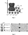
FIG. 1 depicts a simplified drawing of an embodiment of a camera system with a measurement stick. -
FIG. 2 depicts a simplified drawing of an embodiment of a configuration of camera units at a worksite. -
FIG. 3 depicts a simplified perspective drawing of an embodiment of camera units placed in a worksite. -
FIG. 4 depicts a simplified drawing of the collinearity condition. -
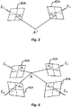
FIG. 5 illustrates the concept of space intersection for two cameras. -
FIG. 6 illustrates the concept of space intersection for four cameras. -
FIG. 7 illustrates a flowchart of an embodiment of a process for determining a position and/or orientation of a camera at a worksite. -
FIG. 8 depicts an embodiment of point projection. -
FIG. 9 depicts an embodiment of line projection. -
FIG. 10 depicts an embodiment of an image with a projection of an outline of a wall from a three-dimensional model. -
Fig. 11 shows an intensity-based fitting plane algorithm successfully aligning a BIM to an edge. -
FIGs. 12 and 13 show embodiments of the projection of the outline of the wall better aligned to the image. -
FIG. 14 depicts an embodiment of a single camera matrix. -
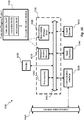
FIG. 15 depicts a block diagram of an embodiment of a computer system. -
FIG. 16 depicts a block diagram of an embodiment of a special-purpose computer system. - In the appended figures, similar components and/or features may have the same reference label. Further, various components of the same type may be distinguished by following the reference label by a dash and a second label that distinguishes among the similar components. If only the first reference label is used in the specification, the description is applicable to any one of the similar components having the same first reference label irrespective of the second reference label.
- The ensuing description provides preferred exemplary embodiment(s) only, and is not intended to limit the scope, applicability, or configuration of the disclosure. Rather, the ensuing description of the preferred exemplary embodiment(s) will provide those skilled in the art with an enabling description for implementing a preferred exemplary embodiment. It is understood that various changes may be made in the function and arrangement of elements without departing from the spirit and scope as set forth in the appended claims.
- While an interior of a building is being finished, connectors, anchors, and the like are attached to the floors, ceilings, and other structures in the building. Further, cuts are made and holes drilled using power saws and drills. Tools, such as special power tools, are used at predetermined locations, such that the tools are operated at numerous, precisely-defined positions in the building. For example, nail guns, power saws, power anchor tools, and the like are used to nail, cut, install fasteners, and/or perform other operations at predetermined points within the building. In some buildings, a large number of electrical, plumbing, and HVAC components are sited and installed, usually with power tools. Additionally, finishing a building interior also uses a number of different tools that are not powered, which are also operated at precisely-defined positions, such as for example reinforcement bar scanners. Positioning both power tools and non-power tools quickly and with precision (e.g., with respect to surrounding walls, ceilings, and floors) can save time and reduce construction costs. In some embodiments, systems and/or methods are described to speed up, reduce manual labor, and/or reduce expense of construction.
- Referring first to
FIG. 1 , a simplified drawing of an embodiment of a camera system is shown. The camera system comprisescamera units 108 and a main processing computer. The camera system comprises two ormore camera units 108. In some embodiments, the camera system comprises two or more measurement sticks 104, and/or two or more main processing computers. - A
camera unit 108 comprises a processor unit, a communication device, and/or one or more imaging devices 112 (e.g., two and/or three imaging devices 112). Theimaging devices 112 have a position and/or orientation that is known relative to other imaging device(s) 112 and/or camera unit(s) 108. Theimaging devices 112 acquire image sequences. The processor unit in thecamera unit 108 processes the image sequences. The communication device transmits and receives data with the main processing computer. - In
FIG. 2 , a simplified drawing of an embodiment of a configuration ofcamera units 108 at a worksite is shown. An operator attachescamera units 108 to a column, wall, etc. The operator can add and/or subtractcamera units 108 depending on a size of the worksite and/or a position of thecamera unit 108. -
FIG. 3 depicts a simplified perspective drawing of an embodiment ofcamera units 108 placed in a worksite. The operator attaches thecamera units 108 to acolumn 304,wall 308,ceiling 312,floor 316,truss 320, etc.Camera units 108, which are modular, allow for quick setup. -
Camera units 108 can be used to determine a three-dimensional position of an object at the worksite. In some embodiments, a collinearity condition, sometimes referred to as collinearity equations, is used in calculating the three-dimensional line equation.FIG. 4 depicts a simplified drawing of the collinearity condition. The collinearity condition represents a geometric relationship wherein a point (A) in an object space, an image of the point (a) on animage plane 404, and a perspective center (L) of theimage plane 404 are on a straight line in three-dimensional space. - The collinearity condition can be expressed by the following equations:


- In the above equations, xa and ya are coordinates of the image of the point (a) (sometimes referred to as photo coordinates); xo and yo are coordinates of the principal point (the principal point is the point on the
image plane 404 onto which the perspective center (L) is projected); f is a focal length of a camera (e.g., of an imaging device 112); XL, YL, and ZL are object space coordinates of the perspective center L; XA, YA, and ZA are object space coordinates of point A; and the m's are functions of the three rotation angles (ω, ϕ, and κ) such that:



- Since the collinearity equations are nonlinear, the linearized forms of the equations are used to iteratively solve many photogrammetric solutions. The collinearity equations can be linearized by using Taylor's theorem. In this manner, the collinearity equations can be written as follows (simplified):


- Space Intersection. Space intersection is the photogrammetric process that estimates 3D coordinates of a point in the object space from photo coordinates observations in a stereo pair.
FIG. 5 illustrates the concept of space intersection. Known values are the exterior orientation parameters of two photographs (L1, L2), photo coordinates of a point (a1, a2) in each photograph, and initial value for the point in object space (A). In some embodiments, the initial value for the point in object space (A) is determined by calculating a first vector starting at the perspective center of the first camera and to photo coordinates of a point on an image plane of the first camera; calculate a second vector for the second camera (e.g., starting at a perspective center of the second camera to a point on an image plane of the second camera); calculating an intersection of the first vector and the second vector, and if an intersection does not exist, finding a point near (e.g., closest point between) the first vector and the second vector. - The following equations shows the linearized form of the collinearity equations for space intersection. Since the exterior orientation parameters of each photograph are known, the object coordinate terms (dXA, dYA, dZA) are estimated iteratively in the linearized form of the collinearity condition equation.


- The following equation shows the matrix form of the previous equations. Subscripts C0 and C1 represent
cameras 0 and 1 (orphotographs 0 and 1), respectively. The solution of the equation can be estimated iteratively using Least-square solution.
- The following table shows the iterative space intersection algorithm.

- Space intersection with multiple cameras. A bundle adjustment technique can be used to solve for the space intersection solution in a multiple camera case.
FIG. 6 illustrates the concept of space intersection for the multiple camera case. Known values are the exterior orientation parameters of the cameras or photographs (L1, L2, L3, and L4), the photo coordinates of a point (a1, a2, a3, and a4), and the initial value for the point in object space (A) is a center of the object space. - The following equation shows a matrix form of space intersection equation for the multiple camera case. In this equation, subscripts C0, C1, C2 and C3 represent
cameras 
- Referring next to
FIG. 7 , a flowchart of an embodiment of aprocess 700 for determining a position and/or orientation of a camera at a worksite is illustrated.Process 700 begins instep 704 with retrieving a model of the worksite. The model is a three-dimensional model. In some embodiments, the model is a Building Information Modeling (BIM) file. - In
step 708, an image of the worksite is retrieved. In some embodiments, the image is stored as an image file, such as a Joint Photographic Experts Group (JPEG), a Tagged Image File Format (TIFF), a Graphics Interchange Format (GIF), and/or a Windows bitmap (BMP) file. The image is acquired by the camera (e.g., using an image sensor in a camera unit 108) at the worksite. - In
step 712, coarse input for a camera position is received. The coarse input for the camera is in relation to the model. In some embodiments, the coarse input for the camera position is received by a user marking an estimated camera position in a computer application (e.g., on the model). The model is projected to a two-dimensional projection based on the coarse input,step 716. - Features in the image are comparted to features in the two-dimensional projection, 720. To compare features in the image to features in the two-dimensional projection, features in the image are identified, which correspond to features in the two-dimensional projection. In some embodiments, a feature is a point. In some embodiments, a feature is a line. For example, an outline of a wall (e.g., four lines) in the two-dimensional projection is overlaid on the image. An outline of the wall in the image is detected. And the position and/or orientation of the camera is calculated so that the outline of the wall in the two-dimensional projection overlaps the outline of the wall in the image. In some embodiments, to determine an overlap, a least-squares fit is used.
- In
optional step 728, an iterative process is used. Instep 728, a determination is made to refine the calculation of the position and/or orientation of the camera. The calculated position and/or orientation of the camera ofstep 724 is fed back intostep 712 as coarse input and/or intostep 720 for comparing features in the image to features of the two-dimensional projection. In some embodiments, different features are used (e.g., a second wall, a third wall, a ceiling, and/or a floor). - In an example approach, an estimation of a camera position and orientation is estimated in relation to a building information model (BIM). Since some BIMs contain a large amount of data, the example approach is semi-automated. In the example approach, the BIM is divided into a plurality of BIM files. In the example approach, only the BIM file(s), of the plurality of BIM files, that corresponds to a locality of the camera is retrieved. The BIM file is retrieved based on user input for the coarse position of the camera.
- After retrieval of the relevant model, the user provides the coarse position of the camera. Algorithms, starting from this coarse position, estimate position and orientation of the camera using both the BIM and the image. The coarsely aligned BIM provides 3D information of the worksite (e.g., dimensions of elements and relative placements of each element at the worksite). To match a BIM to an image, the following equation is used:

where,


such that,
- B corresponds to known two-dimensional points of the image. C corresponds to known internal parameters (e.g., focal length of a lens of the camera). D corresponds to camera orientation and position (unknown). E corresponds to three-dimensional known points (e.g., from the BIM file).
- Initial estimation. An initial projection matrix can be determined using either points or lines. The initial estimation of the projection matrix starts with selecting point correspondences from the BIM and the image. In some embodiments, a system selects lines in both the BIM and the image (e.g., selecting lines from an outline of a wall, ceiling, or floor). In some embodiments, as few as five to nine points are used. In some embodiments, selected points in the image do not have to exactly match BIM points, wherein others' approaches algorithms highly depend on points a user selects. Although a poor initial point selection does not have a significantly negative effect on the accuracy of the estimated position and orientation, it may be more consuming for processing compared to a more accurate initial point selection. Applicant has found that line-based projection is generally more stable than point-based projection. Moreover, line-based estimation has a better performance than point-based estimation in terms of noise resistance from a computational point of view. Although estimation based on line correspondences is considered as a dual of one based on point correspondences, or is regarded projectively equivalent, we find from a numerical point of view, an estimation based on line correspondences is more robust.
-
FIG. 8 depicts an embodiment of a point projection. C1 is a position of a first camera. The first camera has a first image plan 404-1. C2 is a position of a second camera. The second camera has a second image plan 404-2. Points p and q are imaged in the first image plane 404-1 and in the second image plane 404-2. -
FIG. 9 depicts an embodiment of a line projection. C1 is a position of a first camera. The first camera has a first image plane 404-1. C2 is a position of a second camera. The second camera has a second image plane 404-2. Lines l and n are imaged in the first image plane 404-1 and in the second image plane 404-2. - An initial alignment comprises two steps: (1) a projection and (2) a homography. The projection maps the 3D model to the image. The homography uses the points and/or lines from the 3D model (e.g., lines outlining a wall). In some embodiments, the points and/or lines are selected by a user previously. In some embodiments, the system selects lines automatically (e.g., the system is configured to identify a wall, a floor, and/or a ceiling in the 3D model). In some embodiments, the homography uses a perspective from a coarse position of the camera entered by the user.
-
FIG. 10 depicts an embodiment of animage 1000 with aprojection 1004 of an outline of a wall from a 3D model.FIG. 10 demonstrates the projection and the homography steps of the initial estimation. Although the initial estimation is close to aligning theprojection 1004 with awall 1008 in the image, theprojection 1004 can be aligned more closely to thewall 1008. - The
projection 1004 is fitted to edges in theimage 1000. For example, theimage 1000 is converted from color to gray tone. A derivative filter is then applied to the gray-tone image to produce a derivative image. In some embodiments, the derivative filter is a Laplacian filter. In the derivative image, edges are easier to identify. Edges are areas where pixel values change rapidly (sometimes referred to as "corners"). A plane (e.g., projection 1004) is fitted to intensity of edges of theimage 1000. After a parametric plane for each pixel intensity based on neighbor edges is defined, gradient of each pixel of the image edges can be determined from a plane normal vector. In some embodiments, the parametric plane is a virtual plane (not physical) fitted to grayscale values in space (x,y, I(x,y)) where I(x,y) are intensity values. Plane fitting uses gradient of intensities; a normal of a virtual plane defines an edge direction. -
FIG. 11 shows an intensity-based fitting plane algorithm successfully aligning a BIM to an edge. Extrinsic camera parameters (rotation and position) are updated.FIG. 11 shows normal directions for fitted virtual planes np. A first normal direction np1, a second normal direction np2, a third normal direction np3, and a fourth normal direction np4 are shown.FIG. 12 shows an embodiment of theprojection 1004 better aligned to theimage 1000. Extrinsic camera parameters (rotation and position) are updated in each iteration and eventually final camera parameters are generated that align theprojection 1004 and theimage 1000,FIG. 13 . Final camera parameters generate a homography that maps the initial estimation fromFIG. 10 to FIG. 13 . - Extrinsic camera parameters (rotation and position) are calculated based on constraints that fulfill characteristics of rotation and translation matrices. In some embodiments, an accuracy of estimated camera orientation and position for a relatively large room (23x16x10 feet3) is as low as 4 inches. A similar procedure can be done for other walls, ceiling, and/or floor. Each wall provides a different set of camera parameters. Since walls other than the
wall 1008 used to estimate extrinsic parameters were not involved, camera parameters might be biased. To reduce biasing, camera parameters from walls, the ceiling, and/or the floor are used. Using camera parameters from more than one surface (e.g., wall) will reduce errors and render more accurate results. - Referring next to
FIG. 14 , an embodiment for a single camera matrix is shown. The single camera matrix reduces re-projection error using bundle adjustment. Bundle adjustment refines 3D coordinates describing a scene geometry, parameters of the relative motion, and/or optical characteristics of the camera. However, a typical bundle adjustment compensates re-projection errors using several cameras. Yet bias caused by considering walls separately with a modified bundle adjustment(BA) algorithm can reduce errors. Thus in some embodiments, only one camera with parameters for different walls is used (e.g., first parameters for a first wall and second parameters for a second wall).Fig 14 displays how bundle adjustment reduces re-projection error.Reprojection error 1404 is calculated by:

- Referring next to
FIG. 15 , an exemplary environment with which embodiments may be implemented is shown with acomputer system 1500 that can be used by adesigner 1504 to design, for example, electronic designs. Thecomputer system 1500 can include acomputer 1502,keyboard 1522, anetwork router 1512, a printer 1508, and amonitor 1506. Themonitor 1506,processor 1502 andkeyboard 1522 are part of a computer system, which can be a laptop computer, desktop computer, handheld computer, mainframe computer, etc. Themonitor 1506 can be a CRT, flat screen, etc. - A
designer 1504 can input commands into thecomputer 1502 using various input devices, such as a mouse,keyboard 1522, track ball, touch screen, etc. If thecomputer system 1500 comprises a mainframe, adesigner 1504 can access thecomputer 1502 using, for example, a terminal or terminal interface. Additionally, thecomputer 1502 may be connected to a printer 1508 and aserver 1510 using anetwork router 1512, which may connect to theInternet 1518 or a WAN. - The
server 1510 may, for example, be used to store additional software programs and data. In one embodiment, software implementing the systems and methods described herein can be stored on a storage medium in theserver 1510. Thus, the software can be run from the storage medium in theserver 1510. In another embodiment, software implementing the systems and methods described herein can be stored on a storage medium in thecomputer 1502. Thus, the software can be run from the storage medium in thecomputer 1502. Therefore, in this embodiment, the software can be used whether or notcomputer 1502 is connected tonetwork router 1512. Printer 1508 may be connected directly tocomputer 1502, in which case, thecomputer system 1500 can print whether or not it is connected tonetwork router 1512. - With reference to
FIG. 16 , an embodiment of a special-purpose computer system 1600 is shown. The above methods may be implemented by computer-program products that direct a computer system to perform the actions of the above-described methods and components. Each such computer-program product may comprise sets of instructions (codes) embodied on a computer-readable medium that directs the processor of a computer system to perform corresponding actions. The instructions may be configured to run in sequential order, or in parallel (such as under different processing threads), or in a combination thereof. After loading the computer-program products on a general purpose computer system, it is transformed into the special-purpose computer system 1600. - Special-
purpose computer system 1600 comprises acomputer 1502, amonitor 1506 coupled tocomputer 1502, one or more additional user output devices 1630 (optional) coupled tocomputer 1502, one or more user input devices 1640 (e.g., keyboard, mouse, track ball, touch screen) coupled tocomputer 1502, anoptional communications interface 1650 coupled tocomputer 1502, a computer-program product 1605 stored in a tangible computer-readable memory incomputer 1502. Computer-program product 1605 directssystem 1600 to perform the above-described methods.Computer 1502 may include one ormore processors 1660 that communicate with a number of peripheral devices via abus subsystem 1690. These peripheral devices may include user output device(s) 1630, user input device(s) 1640,communications interface 1650, and a storage subsystem, such as random access memory (RAM) 1670 and non-volatile storage drive 1680 (e.g., disk drive, optical drive, solid state drive), which are forms of tangible computer-readable memory. - Computer-
program product 1605 may be stored innon-volatile storage drive 1680 or another computer-readable medium accessible tocomputer 1502 and loaded intomemory 1670. Eachprocessor 1660 may comprise a microprocessor, such as a microprocessor from Intel® or Advanced Micro Devices, Inc.®, or the like. To support computer-program product 1605, thecomputer 1502 runs an operating system that handles the communications ofproduct 1605 with the above-noted components, as well as the communications between the above-noted components in support of the computer-program product 1605. Exemplary operating systems include Windows® or the like from Microsoft Corporation, Solaris® from Sun Microsystems, LINUX, UNIX, and the like. -
User input devices 1640 include all possible types of devices and mechanisms to input information tocomputer 1502. These may include a keyboard, a keypad, a mouse, a scanner, a digital drawing pad, a touch screen incorporated into the display, audio input devices such as voice recognition systems, microphones, and other types of input devices. In various embodiments,user input devices 1640 are typically embodied as a computer mouse, a trackball, a track pad, a joystick, wireless remote, a drawing tablet, a voice command system.User input devices 1640 typically allow a user to select objects, icons, text and the like that appear on themonitor 1506 via a command such as a click of a button or the like.User output devices 1630 include all possible types of devices and mechanisms to output information fromcomputer 1502. These may include a display (e.g., monitor 1506), printers, non-visual displays such as audio output devices, etc. -
Communications interface 1650 provides an interface to other communication networks and devices and may serve as an interface to receive data from and transmit data to other systems, WANs and/or theInternet 1518. Embodiments ofcommunications interface 1650 typically include an Ethernet card, a modem (telephone, satellite, cable, ISDN), a (asynchronous) digital subscriber line (DSL) unit, a FireWire® interface, a USB® interface, a wireless network adapter, and the like. For example,communications interface 1650 may be coupled to a computer network, to a FireWire® bus, or the like. In other embodiments,communications interface 1650 may be physically integrated on the motherboard ofcomputer 1502, and/or may be a software program, or the like. -
RAM 1670 andnon-volatile storage drive 1680 are examples of tangible computer-readable media configured to store data such as computer-program product embodiments of the present invention, including executable computer code, human-readable code, or the like. Other types of tangible computer-readable media include floppy disks, removable hard disks, optical storage media such as CD-ROMs, DVDs, bar codes, semiconductor memories such as flash memories, read-only-memories (ROMs), battery-backed volatile memories, networked storage devices, and the like.RAM 1670 andnon-volatile storage drive 1680 may be configured to store the basic programming and data constructs that provide the functionality of various embodiments of the present invention, as described above. - Software instruction sets that provide the functionality of the present invention may be stored in
RAM 1670 andnon-volatile storage drive 1680. These instruction sets or code may be executed by the processor(s) 1660.RAM 1670 andnon-volatile storage drive 1680 may also provide a repository to store data and data structures used in accordance with the present invention.RAM 1670 andnon-volatile storage drive 1680 may include a number of memories including a main random access memory (RAM) to store of instructions and data during program execution and a read-only memory (ROM) in which fixed instructions are stored.RAM 1670 andnon-volatile storage drive 1680 may include a file storage subsystem providing persistent (non-volatile) storage of program and/or data files.RAM 1670 andnon-volatile storage drive 1680 may also include removable storage systems, such as removable flash memory. -
Bus subsystem 1690 provides a mechanism to allow the various components and subsystems ofcomputer 1502 communicate with each other as intended. Althoughbus subsystem 1690 is shown schematically as a single bus, alternative embodiments of thebus subsystem 1690 may utilize multiple busses or communication paths within thecomputer 1502. - Specific details are given in the above description to provide a thorough understanding of the embodiments. However, it is understood that the embodiments may be practiced without these specific details. For example, circuits may be shown in block diagrams in order not to obscure the embodiments in unnecessary detail. In other instances, well-known circuits, processes, algorithms, structures, and techniques may be shown without unnecessary detail in order to avoid obscuring the embodiments.
- Implementation of the techniques, blocks, steps and means described above may be done in various ways. For example, these techniques, blocks, steps and means may be implemented in hardware, software, or a combination thereof. For a hardware implementation, the processing units may be implemented within one or more application specific integrated circuits (ASICs), digital signal processors (DSPs), digital signal processing devices (DSPDs), programmable logic devices (PLDs), field programmable gate arrays (FPGAs), processors, controllers, micro-controllers, microprocessors, other electronic units designed to perform the functions described above, and/or a combination thereof.
- Also, it is noted that the embodiments may be described as a process which is depicted as a flowchart, a flow diagram, a data flow diagram, a structure diagram, or a block diagram. Although a flowchart may describe the operations as a sequential process, many of the operations can be performed in parallel or concurrently. In addition, the order of the operations may be re-arranged. A process is terminated when its operations are completed, but could have additional steps not included in the figure. A process may correspond to a method, a function, a procedure, a subroutine, a subprogram, etc. When a process corresponds to a function, its termination corresponds to a return of the function to the calling function or the main function.
- Furthermore, embodiments may be implemented by hardware, software, scripting languages, firmware, middleware, microcode, hardware description languages, and/or any combination thereof. When implemented in software, firmware, middleware, scripting language, and/or microcode, the program code or code segments to perform the necessary tasks may be stored in a machine readable medium such as a storage medium. A code segment or machine-executable instruction may represent a procedure, a function, a subprogram, a program, a routine, a subroutine, a module, a software package, a script, a class, or any combination of instructions, data structures, and/or program statements. A code segment may be coupled to another code segment or a hardware circuit by passing and/or receiving information, data, arguments, parameters, and/or memory contents. Information, arguments, parameters, data, etc. may be passed, forwarded, or transmitted via any suitable means including memory sharing, message passing, token passing, network transmission, etc.
- For a firmware and/or software implementation, the methodologies may be implemented with modules (e.g., procedures, functions, and so on) that perform the functions described herein. Any machine-readable medium tangibly embodying instructions may be used in implementing the methodologies described herein. For example, software codes may be stored in a memory. Memory may be implemented within the processor or external to the processor. As used herein the term "memory" refers to any type of long term, short term, volatile, nonvolatile, or other storage medium and is not to be limited to any particular type of memory or number of memories, or type of media upon which memory is stored.
- Moreover, as disclosed herein, the term "storage medium" may represent one or more memories for storing data, including read only memory (ROM), random access memory (RAM), magnetic RAM, core memory, magnetic disk storage mediums, optical storage mediums, flash memory devices and/or other machine readable mediums for storing information. The term "machine-readable medium" includes, but is not limited to portable or fixed storage devices, optical storage devices, wireless channels, and/or various other storage mediums capable of storing that include or carry instruction(s) and/or data.
- While the principles of the disclosure have been described above in connection with specific apparatuses and methods, it is to be clearly understood that this description is made only by way of example and not as limitation on the scope of the disclosure.
- The specific details of particular embodiments may be combined in any suitable manner without departing from the spirit and scope of embodiments of the invention. However, other embodiments of the invention may be directed to specific embodiments relating to each individual aspect, or specific combinations of these individual aspects.
- The above description of exemplary embodiments of the invention has been presented for the purposes of illustration and description. It is not intended to be exhaustive or to limit the invention to the precise form described, and many modifications and variations are possible in light of the teaching above.
- The embodiments were chosen and described in order to explain the principles of the invention and practical applications to thereby enable others skilled in the art to best utilize the invention in various embodiments and with various modifications as are suited to the particular use contemplated.
- Also, it is noted that the embodiments may be described as a process which is depicted as a flowchart, a flow diagram, a data flow diagram, a structure diagram, or a block diagram. Although a flowchart may describe the operations as a sequential process, many of the operations can be performed in parallel or concurrently. In addition, the order of the operations may be re-arranged. A process is terminated when its operations are completed, but could have additional steps not included in the figure. A process may correspond to a method, a function, a procedure, a subroutine, a subprogram, etc.
- A recitation of "a", "an", or "the" is intended to mean "one or more" unless specifically indicated to the contrary.
- All patents, patent applications, publications, and descriptions mentioned here are incorporated by reference in their entirety for all purposes. None is admitted to be prior art.
Claims (15)
- A method for using a camera system to determine a location of a camera unit in relation to a three-dimensional model, the method comprising:retrieving a model of a worksite, wherein the model is a three-dimensional model;retrieving an image of the worksite, wherein the image is acquired using a camera at the worksite;receiving coarse input for a position and/or an orientation of the camera in relation to the model;projecting a feature of the model onto the image;comparing a feature in the image to the feature in model projected onto the image; andcalculating the position and/or the orientation of the camera in relation to the model based on aligning the feature of the model with the image.
- The method of claim 1, the feature of the model comprises a point.
- The method of claim 2, wherein the feature of the model used comprises at least five points and no more than ten points.
- The method of claim 1, wherein the feature of the model comprises a line.
- The method of claim 4, wherein the line corresponds to an edge of a wall, a floor, and/or a ceiling.
- The method of claim 4, wherein the feature of the model comprises outlines of two or more walls.
- The method of claim 1, wherein the feature in the image is identified by analyzing gradients of pixels in the image.
- The method of claim 1, further comprising acquiring the image of the worksite using the camera at the worksite, wherein the camera comprises two image sensors.
- A camera system comprising:a camera configured to acquire an image of a worksite;an electronic model of the worksite; andone or more processors configured to:retrieve the electronic model of the worksite, wherein the electronic model is a three-dimensional model,retrieve the image of the worksite,receive coarse input for a position and/or an orientation of the camera in relation to the electronic model,project a feature of the electronic model onto the image,compare a feature in the image to the feature in the electronic model projected onto the image, andcalculate the position and/or the orientation of the camera in relation to the electronic model based on aligning the feature of the electronic model with the feature in the image.
- The camera system of claim 9, wherein the feature in the electronic model comprises at least five points and no more than ten points.
- The camera system of claim 9, wherein the feature in the electronic model comprises a line.
- The camera system of claim 11, wherein the line corresponds to an edge of a wall, a floor, and/or a ceiling.
- The camera system of claim 11, wherein the feature in the electronic model comprises outlines of two or more walls.
- The camera system of claim 9, wherein the feature in the image is identified by analyzing gradients of pixels in the image.
- A memory device comprising instructions that when executed cause one or more processors to:retrieve a model of a worksite, wherein the model is a three-dimensional model;retrieve an image of the worksite, wherein the image is acquired using a camera at the worksite;receive coarse input for a position and/or an orientation of the camera in relation to the model;project a feature of the model onto the image;compare a feature in the image to the feature of the model projected onto the image; andcalculate the position and/or the orientation of the camera in relation to the model based on aligning the feature of the model with the image.
Applications Claiming Priority (1)
| Application Number | Priority Date | Filing Date | Title |
|---|---|---|---|
| US15/676,023 US10347008B2 (en) | 2017-08-14 | 2017-08-14 | Self positioning camera system to 3D CAD/BIM model |
Publications (2)
| Publication Number | Publication Date |
|---|---|
| EP3444784A1 true EP3444784A1 (en) | 2019-02-20 |
| EP3444784B1 EP3444784B1 (en) | 2025-05-07 |
Family
ID=63442383
Family Applications (1)
| Application Number | Title | Priority Date | Filing Date |
|---|---|---|---|
| EP18188560.9A Active EP3444784B1 (en) | 2017-08-14 | 2018-08-10 | Self positioning camera system to 3d cad/bim model |
Country Status (2)
| Country | Link |
|---|---|
| US (1) | US10347008B2 (en) |
| EP (1) | EP3444784B1 (en) |
Families Citing this family (11)
| Publication number | Priority date | Publication date | Assignee | Title |
|---|---|---|---|---|
| CN112912937B (en) | 2018-10-31 | 2025-03-25 | 米沃奇电动工具公司 | Spatial Awareness Tool System |
| EP3938919A4 (en) * | 2019-04-02 | 2022-05-18 | Buildots Ltd. | DETERMINING THE POSITION OF AN IMAGE CAPTURE DEVICE |
| US10997747B2 (en) | 2019-05-09 | 2021-05-04 | Trimble Inc. | Target positioning with bundle adjustment |
| US11002541B2 (en) | 2019-07-23 | 2021-05-11 | Trimble Inc. | Target positioning with electronic distance measuring and bundle adjustment |
| CN110345920A (en) * | 2019-08-20 | 2019-10-18 | 南通四建集团有限公司 | An automatic synchronization method of scene and model images based on Beidou GNSS and BIM |
| US11295473B2 (en) * | 2019-12-18 | 2022-04-05 | Intel Corporation | Continuous local 3D reconstruction refinement in video |
| WO2021156312A1 (en) * | 2020-02-03 | 2021-08-12 | Unity IPR ApS | Method and system for aligning a digital model of a structure with a video stream |
| US11232582B2 (en) | 2020-04-21 | 2022-01-25 | Here Global B.V. | Visual localization using a three-dimensional model and image segmentation |
| SE2030252A1 (en) * | 2020-08-13 | 2022-02-14 | Nagoon AB | Method performed by a computer system for creation of augmented reality experiences and connection of these to the real world |
| CN112835064B (en) * | 2020-12-31 | 2022-11-01 | 上海蔚建科技有限公司 | Mapping positioning method, system, terminal and medium |
| CN113010936B (en) * | 2021-02-23 | 2023-07-21 | 上海巡智科技有限公司 | Auxiliary construction method, equipment and readable storage medium |
Citations (3)
| Publication number | Priority date | Publication date | Assignee | Title |
|---|---|---|---|---|
| US6985620B2 (en) * | 2000-03-07 | 2006-01-10 | Sarnoff Corporation | Method of pose estimation and model refinement for video representation of a three dimensional scene |
| US20140016821A1 (en) * | 2012-07-12 | 2014-01-16 | Qualcomm Incorporated | Sensor-aided wide-area localization on mobile devices |
| US20170228878A1 (en) * | 2014-05-28 | 2017-08-10 | Elbit Systems Land And C4I Ltd. | Method and system for image georegistration |
Family Cites Families (26)
| Publication number | Priority date | Publication date | Assignee | Title |
|---|---|---|---|---|
| US2685082A (en) | 1951-03-28 | 1954-07-27 | Telecomputing Corp | Position indicating device |
| US2966090A (en) | 1954-12-28 | 1960-12-27 | Gasaccumulator Svenska Ab | Optical distance measuring device |
| FR2630538A1 (en) | 1988-04-22 | 1989-10-27 | Image Technologie | Method, device and video camera for measuring lengths using video images |
| US6064398A (en) | 1993-09-10 | 2000-05-16 | Geovector Corporation | Electro-optic vision systems |
| US5926260A (en) | 1995-01-19 | 1999-07-20 | Laser Technology, Inc. | Compact laser-based distance measuring apparatus |
| US6097429A (en) | 1997-08-01 | 2000-08-01 | Esco Electronics Corporation | Site control unit for video security system |
| US6919880B2 (en) | 2001-06-01 | 2005-07-19 | Smart Technologies Inc. | Calibrating camera offsets to facilitate object position determination using triangulation |
| US7215364B2 (en) | 2002-04-10 | 2007-05-08 | Panx Imaging, Inc. | Digital imaging system using overlapping images to formulate a seamless composite image and implemented using either a digital imaging sensor array |
| KR100556612B1 (en) | 2002-06-29 | 2006-03-06 | 삼성전자주식회사 | Position measuring device and method using laser |
| FI115414B (en) | 2003-07-03 | 2005-04-29 | Sandvik Tamrock Oy | Arrangement for monitoring the location of the mining vehicle in the mine |
| US20060174302A1 (en) | 2005-02-01 | 2006-08-03 | Bryan Mattern | Automated remote monitoring system for construction sites |
| WO2006099059A2 (en) | 2005-03-10 | 2006-09-21 | Witten Technologies, Inc. | Method for correcting a 3d location measured by a tracking system assuming a vertical offset |
| GB2459602B (en) | 2007-02-21 | 2011-09-21 | Pixel Velocity Inc | Scalable system for wide area surveillance |
| US7949150B2 (en) | 2007-04-02 | 2011-05-24 | Objectvideo, Inc. | Automatic camera calibration and geo-registration using objects that provide positional information |
| WO2009032366A2 (en) | 2007-05-22 | 2009-03-12 | Vidsys, Inc. | Optimal routing of audio, video, and control data through heterogeneous networks |
| EP2116919A1 (en) | 2008-05-09 | 2009-11-11 | MBDA UK Limited | display of 3-dimensional objects |
| JP5624615B2 (en) | 2009-06-23 | 2014-11-12 | ライカ・ジオシステムズ・アクチェンゲゼルシャフトLeica Geosystems Ag | TRACKING METHOD AND MEASUREMENT SYSTEM HAVING LASER TRACKER |
| EP2499827A4 (en) | 2009-11-13 | 2018-01-03 | Pixel Velocity, Inc. | Method for tracking an object through an environment across multiple cameras |
| DE102009058802B4 (en) | 2009-12-18 | 2018-03-29 | Airbus Operations Gmbh | Arrangement for the combined representation of a real and a virtual model |
| ES2817800T3 (en) | 2010-04-22 | 2021-04-08 | Metronor As | Optical measurement system |
| AU2011362799B2 (en) * | 2011-03-18 | 2016-02-25 | Apple Inc. | 3D streets |
| US10139985B2 (en) * | 2012-06-22 | 2018-11-27 | Matterport, Inc. | Defining, displaying and interacting with tags in a three-dimensional model |
| US9706264B2 (en) | 2013-02-06 | 2017-07-11 | Robert Bosch Gmbh | Multiple field-of-view video streaming |
| US9687950B2 (en) | 2013-03-13 | 2017-06-27 | Trimble Inc. | System and method for positioning a tool in a work space |
| US10203762B2 (en) * | 2014-03-11 | 2019-02-12 | Magic Leap, Inc. | Methods and systems for creating virtual and augmented reality |
| EP3034995B1 (en) * | 2014-12-19 | 2024-02-28 | Leica Geosystems AG | Method for determining a position and orientation offset of a geodetic surveying device and corresponding measuring device |
-
2017
- 2017-08-14 US US15/676,023 patent/US10347008B2/en active Active
-
2018
- 2018-08-10 EP EP18188560.9A patent/EP3444784B1/en active Active
Patent Citations (3)
| Publication number | Priority date | Publication date | Assignee | Title |
|---|---|---|---|---|
| US6985620B2 (en) * | 2000-03-07 | 2006-01-10 | Sarnoff Corporation | Method of pose estimation and model refinement for video representation of a three dimensional scene |
| US20140016821A1 (en) * | 2012-07-12 | 2014-01-16 | Qualcomm Incorporated | Sensor-aided wide-area localization on mobile devices |
| US20170228878A1 (en) * | 2014-05-28 | 2017-08-10 | Elbit Systems Land And C4I Ltd. | Method and system for image georegistration |
Also Published As
| Publication number | Publication date |
|---|---|
| EP3444784B1 (en) | 2025-05-07 |
| US10347008B2 (en) | 2019-07-09 |
| US20190051014A1 (en) | 2019-02-14 |
Similar Documents
| Publication | Publication Date | Title |
|---|---|---|
| EP3444784B1 (en) | Self positioning camera system to 3d cad/bim model | |
| US10341618B2 (en) | Infrastructure positioning camera system | |
| US10646975B2 (en) | Measurement, layout, marking, firestop stick | |
| US10406645B2 (en) | Calibration approach for camera placement | |
| US20240249141A1 (en) | Monitoring construction of a structure | |
| US10977857B2 (en) | Apparatus and method of three-dimensional reverse modeling of building structure by using photographic images | |
| US9687950B2 (en) | System and method for positioning a tool in a work space | |
| EP1993072A1 (en) | Method for comparison of 3D computer model and as-built situation of an industrial plant | |
| EP3459682B1 (en) | 3d tool tracking & positioning using cameras | |
| US12524962B2 (en) | Computer vision systems and methods for end to end image inspection | |
| US10997747B2 (en) | Target positioning with bundle adjustment | |
| JP2017151026A (en) | Three-dimensional information acquisition apparatus, three-dimensional information acquisition method, and program | |
| JP2020012774A (en) | Method for measuring building | |
| JP6770826B2 (en) | Automatic collimation method and automatic collimation device for measuring the placement position of structures | |
| CN111523334A (en) | Method and device for setting virtual forbidden zone, terminal equipment, label and storage medium | |
| JP7144991B2 (en) | Autonomous mobile device, autonomous mobile program and position estimation system | |
| US20220222909A1 (en) | Systems and Methods for Adjusting Model Locations and Scales Using Point Clouds | |
| CN110058260A (en) | Method for orienting the map of LIDAR system | |
| CN114510035A (en) | Robot remote surveying method, device and storage medium | |
| CN113077500A (en) | Panoramic viewpoint positioning and attitude determining method, system, equipment and medium based on plane graph | |
| JP7743784B2 (en) | Augmented reality display device, method, and program | |
| WO2026004279A1 (en) | Point cloud merging device and point cloud merging method | |
| JP2025038766A (en) | MOBILE BODY AND METHOD FOR DETECTING POSITION OF MOBILE BODY | |
| WO2024185470A1 (en) | Installation object management system | |
| CN112053586A (en) | Vehicle position confirmation method and device based on infrared distance meter |
Legal Events
| Date | Code | Title | Description |
|---|---|---|---|
| PUAI | Public reference made under article 153(3) epc to a published international application that has entered the european phase |
Free format text: ORIGINAL CODE: 0009012 |
|
| STAA | Information on the status of an ep patent application or granted ep patent |
Free format text: STATUS: THE APPLICATION HAS BEEN PUBLISHED |
|
| AK | Designated contracting states |
Kind code of ref document: A1 Designated state(s): AL AT BE BG CH CY CZ DE DK EE ES FI FR GB GR HR HU IE IS IT LI LT LU LV MC MK MT NL NO PL PT RO RS SE SI SK SM TR |
|
| AX | Request for extension of the european patent |
Extension state: BA ME |
|
| STAA | Information on the status of an ep patent application or granted ep patent |
Free format text: STATUS: REQUEST FOR EXAMINATION WAS MADE |
|
| 17P | Request for examination filed |
Effective date: 20190819 |
|
| RBV | Designated contracting states (corrected) |
Designated state(s): AL AT BE BG CH CY CZ DE DK EE ES FI FR GB GR HR HU IE IS IT LI LT LU LV MC MK MT NL NO PL PT RO RS SE SI SK SM TR |
|
| STAA | Information on the status of an ep patent application or granted ep patent |
Free format text: STATUS: EXAMINATION IS IN PROGRESS |
|
| 17Q | First examination report despatched |
Effective date: 20200327 |
|
| GRAP | Despatch of communication of intention to grant a patent |
Free format text: ORIGINAL CODE: EPIDOSNIGR1 |
|
| STAA | Information on the status of an ep patent application or granted ep patent |
Free format text: STATUS: GRANT OF PATENT IS INTENDED |
|
| INTG | Intention to grant announced |
Effective date: 20250113 |
|
| GRAS | Grant fee paid |
Free format text: ORIGINAL CODE: EPIDOSNIGR3 |
|
| GRAA | (expected) grant |
Free format text: ORIGINAL CODE: 0009210 |
|
| STAA | Information on the status of an ep patent application or granted ep patent |
Free format text: STATUS: THE PATENT HAS BEEN GRANTED |
|
| AK | Designated contracting states |
Kind code of ref document: B1 Designated state(s): AL AT BE BG CH CY CZ DE DK EE ES FI FR GB GR HR HU IE IS IT LI LT LU LV MC MK MT NL NO PL PT RO RS SE SI SK SM TR |
|
| REG | Reference to a national code |
Ref country code: GB Ref legal event code: FG4D |
|
| REG | Reference to a national code |
Ref country code: CH Ref legal event code: EP |
|
| REG | Reference to a national code |
Ref country code: DE Ref legal event code: R096 Ref document number: 602018081679 Country of ref document: DE |
|
| REG | Reference to a national code |
Ref country code: IE Ref legal event code: FG4D |
|
| REG | Reference to a national code |
Ref country code: NL Ref legal event code: MP Effective date: 20250507 |
|
| PG25 | Lapsed in a contracting state [announced via postgrant information from national office to epo] |
Ref country code: PT Free format text: LAPSE BECAUSE OF FAILURE TO SUBMIT A TRANSLATION OF THE DESCRIPTION OR TO PAY THE FEE WITHIN THE PRESCRIBED TIME-LIMIT Effective date: 20250908 Ref country code: FI Free format text: LAPSE BECAUSE OF FAILURE TO SUBMIT A TRANSLATION OF THE DESCRIPTION OR TO PAY THE FEE WITHIN THE PRESCRIBED TIME-LIMIT Effective date: 20250507 Ref country code: ES Free format text: LAPSE BECAUSE OF FAILURE TO SUBMIT A TRANSLATION OF THE DESCRIPTION OR TO PAY THE FEE WITHIN THE PRESCRIBED TIME-LIMIT Effective date: 20250507 |
|
| PGFP | Annual fee paid to national office [announced via postgrant information from national office to epo] |
Ref country code: DE Payment date: 20250827 Year of fee payment: 8 |
|
| REG | Reference to a national code |
Ref country code: LT Ref legal event code: MG9D |
|
| PG25 | Lapsed in a contracting state [announced via postgrant information from national office to epo] |
Ref country code: NO Free format text: LAPSE BECAUSE OF FAILURE TO SUBMIT A TRANSLATION OF THE DESCRIPTION OR TO PAY THE FEE WITHIN THE PRESCRIBED TIME-LIMIT Effective date: 20250807 Ref country code: GR Free format text: LAPSE BECAUSE OF FAILURE TO SUBMIT A TRANSLATION OF THE DESCRIPTION OR TO PAY THE FEE WITHIN THE PRESCRIBED TIME-LIMIT Effective date: 20250808 |
|
| PG25 | Lapsed in a contracting state [announced via postgrant information from national office to epo] |
Ref country code: PL Free format text: LAPSE BECAUSE OF FAILURE TO SUBMIT A TRANSLATION OF THE DESCRIPTION OR TO PAY THE FEE WITHIN THE PRESCRIBED TIME-LIMIT Effective date: 20250507 Ref country code: NL Free format text: LAPSE BECAUSE OF FAILURE TO SUBMIT A TRANSLATION OF THE DESCRIPTION OR TO PAY THE FEE WITHIN THE PRESCRIBED TIME-LIMIT Effective date: 20250507 |
|
| REG | Reference to a national code |
Ref country code: AT Ref legal event code: MK05 Ref document number: 1793334 Country of ref document: AT Kind code of ref document: T Effective date: 20250507 |
|
| PG25 | Lapsed in a contracting state [announced via postgrant information from national office to epo] |
Ref country code: BG Free format text: LAPSE BECAUSE OF FAILURE TO SUBMIT A TRANSLATION OF THE DESCRIPTION OR TO PAY THE FEE WITHIN THE PRESCRIBED TIME-LIMIT Effective date: 20250507 |
|
| PGFP | Annual fee paid to national office [announced via postgrant information from national office to epo] |
Ref country code: GB Payment date: 20250826 Year of fee payment: 8 |
|
| PG25 | Lapsed in a contracting state [announced via postgrant information from national office to epo] |
Ref country code: HR Free format text: LAPSE BECAUSE OF FAILURE TO SUBMIT A TRANSLATION OF THE DESCRIPTION OR TO PAY THE FEE WITHIN THE PRESCRIBED TIME-LIMIT Effective date: 20250507 |
|
| PG25 | Lapsed in a contracting state [announced via postgrant information from national office to epo] |
Ref country code: AT Free format text: LAPSE BECAUSE OF FAILURE TO SUBMIT A TRANSLATION OF THE DESCRIPTION OR TO PAY THE FEE WITHIN THE PRESCRIBED TIME-LIMIT Effective date: 20250507 |
|
| PGFP | Annual fee paid to national office [announced via postgrant information from national office to epo] |
Ref country code: FR Payment date: 20250825 Year of fee payment: 8 |
|
| PG25 | Lapsed in a contracting state [announced via postgrant information from national office to epo] |
Ref country code: RS Free format text: LAPSE BECAUSE OF FAILURE TO SUBMIT A TRANSLATION OF THE DESCRIPTION OR TO PAY THE FEE WITHIN THE PRESCRIBED TIME-LIMIT Effective date: 20250807 |
|
| PG25 | Lapsed in a contracting state [announced via postgrant information from national office to epo] |
Ref country code: IS Free format text: LAPSE BECAUSE OF FAILURE TO SUBMIT A TRANSLATION OF THE DESCRIPTION OR TO PAY THE FEE WITHIN THE PRESCRIBED TIME-LIMIT Effective date: 20250907 |
|
| PG25 | Lapsed in a contracting state [announced via postgrant information from national office to epo] |
Ref country code: LV Free format text: LAPSE BECAUSE OF FAILURE TO SUBMIT A TRANSLATION OF THE DESCRIPTION OR TO PAY THE FEE WITHIN THE PRESCRIBED TIME-LIMIT Effective date: 20250507 |
|
| PG25 | Lapsed in a contracting state [announced via postgrant information from national office to epo] |
Ref country code: SM Free format text: LAPSE BECAUSE OF FAILURE TO SUBMIT A TRANSLATION OF THE DESCRIPTION OR TO PAY THE FEE WITHIN THE PRESCRIBED TIME-LIMIT Effective date: 20250507 Ref country code: DK Free format text: LAPSE BECAUSE OF FAILURE TO SUBMIT A TRANSLATION OF THE DESCRIPTION OR TO PAY THE FEE WITHIN THE PRESCRIBED TIME-LIMIT Effective date: 20250507 |
|
| PG25 | Lapsed in a contracting state [announced via postgrant information from national office to epo] |
Ref country code: CZ Free format text: LAPSE BECAUSE OF FAILURE TO SUBMIT A TRANSLATION OF THE DESCRIPTION OR TO PAY THE FEE WITHIN THE PRESCRIBED TIME-LIMIT Effective date: 20250507 |
|
| PG25 | Lapsed in a contracting state [announced via postgrant information from national office to epo] |
Ref country code: EE Free format text: LAPSE BECAUSE OF FAILURE TO SUBMIT A TRANSLATION OF THE DESCRIPTION OR TO PAY THE FEE WITHIN THE PRESCRIBED TIME-LIMIT Effective date: 20250507 |
|
| PG25 | Lapsed in a contracting state [announced via postgrant information from national office to epo] |
Ref country code: SK Free format text: LAPSE BECAUSE OF FAILURE TO SUBMIT A TRANSLATION OF THE DESCRIPTION OR TO PAY THE FEE WITHIN THE PRESCRIBED TIME-LIMIT Effective date: 20250507 Ref country code: RO Free format text: LAPSE BECAUSE OF FAILURE TO SUBMIT A TRANSLATION OF THE DESCRIPTION OR TO PAY THE FEE WITHIN THE PRESCRIBED TIME-LIMIT Effective date: 20250507 |
|
| PG25 | Lapsed in a contracting state [announced via postgrant information from national office to epo] |
Ref country code: IT Free format text: LAPSE BECAUSE OF FAILURE TO SUBMIT A TRANSLATION OF THE DESCRIPTION OR TO PAY THE FEE WITHIN THE PRESCRIBED TIME-LIMIT Effective date: 20250507 |
|
| REG | Reference to a national code |
Ref country code: DE Ref legal event code: R097 Ref document number: 602018081679 Country of ref document: DE |
|
| PLBE | No opposition filed within time limit |
Free format text: ORIGINAL CODE: 0009261 |
|
| STAA | Information on the status of an ep patent application or granted ep patent |
Free format text: STATUS: NO OPPOSITION FILED WITHIN TIME LIMIT |
|
| REG | Reference to a national code |
Ref country code: CH Ref legal event code: L10 Free format text: ST27 STATUS EVENT CODE: U-0-0-L10-L00 (AS PROVIDED BY THE NATIONAL OFFICE) Effective date: 20260318 |
|
| REG | Reference to a national code |
Ref country code: CH Ref legal event code: H13 Free format text: ST27 STATUS EVENT CODE: U-0-0-H10-H13 (AS PROVIDED BY THE NATIONAL OFFICE) Effective date: 20260324 |
|
| PG25 | Lapsed in a contracting state [announced via postgrant information from national office to epo] |
Ref country code: MC Free format text: LAPSE BECAUSE OF FAILURE TO SUBMIT A TRANSLATION OF THE DESCRIPTION OR TO PAY THE FEE WITHIN THE PRESCRIBED TIME-LIMIT Effective date: 20250507 |
|
| 26N | No opposition filed |
Effective date: 20260210 |
|
| PG25 | Lapsed in a contracting state [announced via postgrant information from national office to epo] |
Ref country code: LU Free format text: LAPSE BECAUSE OF NON-PAYMENT OF DUE FEES Effective date: 20250810 |
|
| PG25 | Lapsed in a contracting state [announced via postgrant information from national office to epo] |
Ref country code: CH Free format text: LAPSE BECAUSE OF NON-PAYMENT OF DUE FEES Effective date: 20250831 |
|
| REG | Reference to a national code |
Ref country code: BE Ref legal event code: MM Effective date: 20250831 |
|
| PG25 | Lapsed in a contracting state [announced via postgrant information from national office to epo] |
Ref country code: LT Free format text: LAPSE BECAUSE OF FAILURE TO SUBMIT A TRANSLATION OF THE DESCRIPTION OR TO PAY THE FEE WITHIN THE PRESCRIBED TIME-LIMIT Effective date: 20250507 |
|
| PG25 | Lapsed in a contracting state [announced via postgrant information from national office to epo] |
Ref country code: IE Free format text: LAPSE BECAUSE OF NON-PAYMENT OF DUE FEES Effective date: 20250810 Ref country code: BE Free format text: LAPSE BECAUSE OF NON-PAYMENT OF DUE FEES Effective date: 20250831 |
|
| PG25 | Lapsed in a contracting state [announced via postgrant information from national office to epo] |
Ref country code: SE Free format text: LAPSE BECAUSE OF FAILURE TO SUBMIT A TRANSLATION OF THE DESCRIPTION OR TO PAY THE FEE WITHIN THE PRESCRIBED TIME-LIMIT Effective date: 20250507 |