EP3444647A1 - Optical fiber protection structure and method for producing optical element - Google Patents
Optical fiber protection structure and method for producing optical element Download PDFInfo
- Publication number
- EP3444647A1 EP3444647A1 EP17782117.0A EP17782117A EP3444647A1 EP 3444647 A1 EP3444647 A1 EP 3444647A1 EP 17782117 A EP17782117 A EP 17782117A EP 3444647 A1 EP3444647 A1 EP 3444647A1
- Authority
- EP
- European Patent Office
- Prior art keywords
- fiber
- accommodation groove
- optical
- bare
- resin
- Prior art date
- Legal status (The legal status is an assumption and is not a legal conclusion. Google has not performed a legal analysis and makes no representation as to the accuracy of the status listed.)
- Withdrawn
Links
- 239000013307 optical fiber Substances 0.000 title claims abstract description 157
- 230000003287 optical effect Effects 0.000 title claims abstract description 112
- 238000004519 manufacturing process Methods 0.000 title claims abstract description 43
- 239000000835 fiber Substances 0.000 claims abstract description 282
- 239000011347 resin Substances 0.000 claims abstract description 245
- 229920005989 resin Polymers 0.000 claims abstract description 245
- 230000004308 accommodation Effects 0.000 claims abstract description 148
- 238000007789 sealing Methods 0.000 claims abstract description 5
- 230000017525 heat dissipation Effects 0.000 claims description 62
- 238000005253 cladding Methods 0.000 claims description 11
- 238000000034 method Methods 0.000 claims description 5
- 230000006866 deterioration Effects 0.000 abstract description 20
- 230000000116 mitigating effect Effects 0.000 abstract description 4
- 239000000463 material Substances 0.000 description 20
- 230000004927 fusion Effects 0.000 description 18
- 230000001902 propagating effect Effects 0.000 description 11
- 238000010586 diagram Methods 0.000 description 7
- 238000007526 fusion splicing Methods 0.000 description 6
- 230000015572 biosynthetic process Effects 0.000 description 2
- 230000000694 effects Effects 0.000 description 1
- 239000011521 glass Substances 0.000 description 1
- 230000005764 inhibitory process Effects 0.000 description 1
- 239000010453 quartz Substances 0.000 description 1
- VYPSYNLAJGMNEJ-UHFFFAOYSA-N silicon dioxide Inorganic materials O=[Si]=O VYPSYNLAJGMNEJ-UHFFFAOYSA-N 0.000 description 1
- 230000008961 swelling Effects 0.000 description 1
Images





Classifications
-
- G—PHYSICS
- G02—OPTICS
- G02B—OPTICAL ELEMENTS, SYSTEMS OR APPARATUS
- G02B6/00—Light guides; Structural details of arrangements comprising light guides and other optical elements, e.g. couplings
- G02B6/24—Coupling light guides
- G02B6/255—Splicing of light guides, e.g. by fusion or bonding
- G02B6/2558—Reinforcement of splice joint
-
- G—PHYSICS
- G02—OPTICS
- G02B—OPTICAL ELEMENTS, SYSTEMS OR APPARATUS
- G02B6/00—Light guides; Structural details of arrangements comprising light guides and other optical elements, e.g. couplings
- G02B6/24—Coupling light guides
- G02B6/255—Splicing of light guides, e.g. by fusion or bonding
-
- G—PHYSICS
- G02—OPTICS
- G02B—OPTICAL ELEMENTS, SYSTEMS OR APPARATUS
- G02B6/00—Light guides; Structural details of arrangements comprising light guides and other optical elements, e.g. couplings
- G02B6/24—Coupling light guides
- G02B6/36—Mechanical coupling means
- G02B6/3628—Mechanical coupling means for mounting fibres to supporting carriers
- G02B6/3632—Mechanical coupling means for mounting fibres to supporting carriers characterised by the cross-sectional shape of the mechanical coupling means
- G02B6/3636—Mechanical coupling means for mounting fibres to supporting carriers characterised by the cross-sectional shape of the mechanical coupling means the mechanical coupling means being grooves
-
- G—PHYSICS
- G02—OPTICS
- G02B—OPTICAL ELEMENTS, SYSTEMS OR APPARATUS
- G02B6/00—Light guides; Structural details of arrangements comprising light guides and other optical elements, e.g. couplings
- G02B6/24—Coupling light guides
- G02B6/36—Mechanical coupling means
- G02B6/3628—Mechanical coupling means for mounting fibres to supporting carriers
- G02B6/3648—Supporting carriers of a microbench type, i.e. with micromachined additional mechanical structures
- G02B6/3652—Supporting carriers of a microbench type, i.e. with micromachined additional mechanical structures the additional structures being prepositioning mounting areas, allowing only movement in one dimension, e.g. grooves, trenches or vias in the microbench surface, i.e. self aligning supporting carriers
Definitions
- the present invention relates to an optical fiber protection structure and a method of manufacturing an optical element, and more particularly to an optical fiber protection structure that receives at least a portion of an optical fiber therein and an optical combiner structure using the same.
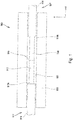
- FIG. 1 is a plan view showing an optical combiner structure 500 to which such a conventional optical fiber protection structure has been applied. As shown in Fig.
- a fusion splice portion 519 and bare fiber exposure portions 517 and 518 of optical fibers 511 and 512 are received within a fiber accommodation groove 521 of a fiber accommodation portion 520, which has a high tensile strength.
- those portions are protected from external forces such as impact or vibration.
- portions 517A and 518A located between the bare fiber exposure portions 517, 518 and coverings 513, 514 are bared in the optical combiner structure 500. Therefore, moisture may be introduced from such portions 517A and 518A so that the coverings 513 and 514 swell so as to compress the optical fibers 511 and 512. In this case, the optical characteristics of the optical fibers, such as the beam quality and the numerical aperture, may be deteriorated.
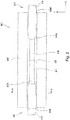
- FIG. 2 is a plan view showing an optical combiner structure 600 to which such a conventional optical fiber protection structure has been applied
- Figs. 3 and 4 are cross-sectional views of the optical combiner structure 600 illustrated in Fig. 2 , taken along line A-A.
- the optical combiner structure 600 includes optical fibers 611 and 612 and a fiber accommodation portion 620 in which a fiber accommodation groove 621 is formed to receive a portion of the optical fibers 611 and 612.
- resins 640A and 640B are filled into portions of the fiber accommodation groove 621 where a boundary portion 617A between a bare fiber exposure portion 617 and a covering 613 and a boundary portion 618A between a bare fiber exposure portion 618 and a covering 614 are respectively located.
- the boundary portions 617A and 618A between the bare fiber exposure portions 617, 618 and the coverings 613, 614 are sealed from an exterior of the boundary portions 617A and 618A. Therefore, according to the optical combiner structure 600, moisture is prevented from being introduced from those portions 617A and 618A.
- those resins 640A and 640B are formed of a material having a low refractive index in order to prevent light propagating through the optical fibers 611 and 612 from leaking into the structure 600.
- Fig. 3 shows a state in which the resin 640A has swelled
- Fig. 4 shows a state in which the resin 640A has shrunk.
- the resins 640A and 640B may be formed of a material having a low rate of cure shrinkage to reduce the stresses.
- the number of currently available materials that have both properties of a low rate of cure shrinkage and a low refractive index are very small. Therefore, when the resins 640A and 640B are formed of a material having a low refractive index in order to prevent light propagating through the optical fibers 611 and 612 from leaking into the structure 600, then it is difficult to use a material having a low rate of cure shrinkage.
- the optical combiner structure 600 has difficulties in solving both of problems to prevent generation of microbend and leakage of light. In this aspect, the optical characteristics of the optical fibers may problematically be deteriorated.
- a first object of the present invention is to provide an optical fiber protection structure capable of mitigating deterioration of optical characteristics of an optical fiber under a high-temperature environment.
- a second object of the present invention is to provide a method of manufacturing an optical element that can avoid deterioration of optical characteristics.
- an optical fiber protection structure capable of mitigating deterioration of optical characteristics of an optical fiber under a high-temperature environment.
- This optical fiber protection structure protects a bare fiber exposure portion in which a bare fiber is exposed from a covering of at least one optical fiber.
- the optical fiber protection structure has a fiber accommodation portion having a fiber accommodation groove that receives the bare fiber exposure portion therein, a fixation resin filled within the fiber accommodation groove for fixing a portion of the covering within the fiber accommodation groove, and two seal resins for sealing a space between the bare fiber and the covering on both ends of the bare fiber exposure portion. At least one of the two seal resins is formed so as to be spaced from an inner surface of the fiber accommodation groove.
- an optical fiber protection structure capable of mitigating deterioration of optical characteristics of an optical fiber under a high-temperature environment.
- This optical fiber protection structure protects a bare fiber exposure portion in which a bare fiber is exposed from a covering of at least one optical fiber.
- the optical fiber protection structure has a fiber accommodation portion having a fiber accommodation groove that receives the bare fiber exposure portion therein, a fixation resin filled within the fiber accommodation groove for fixing a portion of the covering within the fiber accommodation groove, and a single seal resin for sealing a space between the bare fiber and the covering on both ends of the bare fiber exposure portion.
- the single seal resin is formed so as to be spaced from an inner surface of the fiber accommodation groove.
- a single seal resin seals a space between the bare fiber and the covering on both ends of the bare fiber exposure portion, moisture is prevented from being introduced into the optical fiber from between the bare fiber and the covering. Furthermore, since the single seal resin is formed so as to be spaced from the inner surface of the fiber accommodation groove, the seal resin can expand isotropically. Accordingly, microbend is prevented from being generated in the optical fiber under a high-temperature environment. As a result, deterioration of the optical characteristics of the optical fiber is mitigated under a high-temperature environment.
- the seal resin may preferably have a refractive index lower than that of a cladding in the bare fiber. In this case, light propagating through the optical fiber is prevented from leaking out. Furthermore, the seal resin may have a thermal conductivity higher than those of a cladding in the bare fiber and the covering. In this case, heat generated by light propagating through the optical fiber is dissipated to an exterior of the optical combiner structure.
- the optical fiber protection structure may further include a heat dissipation resin having a thermal conductivity higher than those of a cladding in the bare fiber and the covering.
- the heat dissipation resin may cover an outer circumference of the covering located within the fiber accommodation groove.
- the heat dissipation resin is formed so as to be spaced from the inner surface of the fiber accommodation groove.
- heat generated by light propagating through the optical fiber is dissipated to an exterior of the optical combiner structure.
- at least a portion of the heat dissipation resin may preferably be in contact with the seal resin.
- at least a portion of the heat dissipation resin may preferably be in contact with the fixation resin.
- This manufacturing method of an optical element is to manufacture an optical element using an optical fiber protection structure for protecting a bare fiber exposure portion in which a bare fiber is exposed from a covering of at least one optical fiber.
- two seal resins are first formed on both ends of the bare fiber exposure portion to seal a space between the bare fiber and the covering such that at least one of the two seal resins has such a thickness so as not to reach an inner surface of a fiber accommodation groove formed in a fiber accommodation portion when the bare fiber exposure portion is accommodated within the fiber accommodation groove.
- the bare fiber exposure portion is accommodated within the fiber accommodation groove of the fiber accommodation portion such that the at least one of the two seal resins is spaced from the inner surface of the fiber accommodation groove. Then a fixation resin is filled into the fiber accommodation groove to fix a portion of the covering accommodated in the fiber accommodation groove to the fiber accommodation groove to complete the optical element.
- two seal resins are formed before the optical fiber is accommodated in the fiber accommodation groove.
- they can shrink isotropically. Therefore, microbend is prevented from being generated in the optical fiber during the manufacturing process. As a result, deterioration of the optical characteristics of the optical fiber is mitigated at the manufacturing stage.
- the seal resins can thus shrink isotropically, generation of microbend is suppressed even if the seal resins are formed of a material having a high rate of cure shrinkage. Therefore, the seal resins can be formed of a material having a low refractive index.
- This manufacturing method of an optical element is to manufacture an optical element using an optical fiber protection structure for protecting a bare fiber exposure portion in which a bare fiber is exposed from a covering of at least one optical fiber.
- a single seal resin is first formed to seal a space between the bare fiber and the covering on both ends of the bare fiber exposure portion such that the single seal resin has such a thickness so as not to reach an inner surface of a fiber accommodation groove formed in a fiber accommodation portion when the bare fiber exposure portion is accommodated within the fiber accommodation groove.
- the bare fiber exposure portion is accommodated within the fiber accommodation groove of the fiber accommodation portion such that the single seal resin is spaced from the inner surface of the fiber accommodation groove.
- a fixation resin is filled into the fiber accommodation groove to fix a portion of the covering accommodated in the fiber accommodation groove to the fiber accommodation groove to complete the optical element.
- a single seal resin is formed before the optical fiber is accommodated in the fiber accommodation groove.
- the single seal resin can shrink isotropically. Therefore, microbend is prevented from being generated in the optical fiber during the manufacturing process. As a result, deterioration of the optical characteristics of the optical fiber is mitigated at the manufacturing stage.
- the seal resin can thus shrink isotropically, generation of microbend is suppressed even if the seal resin is formed of a material having a high rate of cure shrinkage. Therefore, the seal resin can be formed of a material having a low refractive index.
- a heat dissipation resin having a thermal conductivity higher than those of a cladding in the bare fiber and the covering may be formed on an outer circumference of the covering such that the heat dissipation resin has such a thickness so as not to reach the inner surface of the fiber accommodation groove when the bare fiber exposure portion is accommodated within the fiber accommodation groove.
- the seal resin and the heat dissipation resin may be spaced from the inner surface of the fiber accommodation groove. This configuration can produce an optical element that can dissipate heat generated by light propagating through the optical fiber to an exterior of the optical combiner structure.
- the seal resin can expand isotropically. Therefore, microbend is prevented from being generated in the optical fiber under a high-temperature environment. As a result, deterioration of the optical characteristics of the optical fiber is mitigated under a high-temperature environment.
- the seal resin since the single seal resin is formed so as to be spaced from the inner surface of the fiber accommodation groove, the seal resin can expand isotropically. Therefore, microbend is prevented from being generated in the optical fiber under a high-temperature environment. As a result, deterioration of the optical characteristics of the optical fiber is mitigated under a high-temperature environment.
- two seal resins can be formed before the optical fiber is accommodated in the fiber accommodation groove. Therefore, microbend is prevented from being generated in the optical fiber during the manufacturing process. As a result, deterioration of the optical characteristics of the optical fiber is mitigated at the manufacturing stage, and the seal resins can be formed of a material having a low refractive index.
- a single seal resin can be formed before the optical fiber is accommodated in the fiber accommodation groove. Therefore, microbend is prevented from being generated in the optical fiber during the manufacturing stage. As a result, deterioration of the optical characteristics of the optical fiber is mitigated at the manufacturing stage, and the seal resin can be formed of a material having a low refractive index.
- FIG. 5 to 20B Embodiments of an optical fiber protection structure and an optical combiner structure using such an optical fiber protection structure according to the present invention will be described in detail below with reference to Figs. 5 to 20B .
- the same or corresponding components are denoted by the same or corresponding reference numerals and will not be described below repetitively.
- the scales or dimensions of components may be exaggerated, or some components may be omitted.
- Fig. 5 is a plan view showing an optical combiner structure 1 according to a first embodiment of the present invention
- Fig. 6 is a cross-sectional view taken along line B-B of Fig. 5
- the optical combiner structure 1 includes an optical combiner 10 having optical fibers 11 and 12 connected to each other by fusion splicing and a fiber accommodation portion 20 that protects a fusion splice portion 19 between the optical fibers 11 and 12.
- the optical combiner 10 has a first optical fiber 11, a second optical fiber 12, and a fusion splice portion 19 at which the first optical fiber 11 and the second optical fiber 12 are connected to each other by fusion splicing.
- the fiber accommodation portion 20 serves to protect the optical fibers 11 and 12 and the fusion splice portion 19 from external forces, impact, and vibration.
- Fig. 7 is a cross-sectional view taken along line C-C of Fig. 5
- Fig. 8 is a cross-sectional view taken along line D-D of Fig. 5
- the fiber accommodation portion 20 is in the form of a generally rectangular parallelepiped with a longitudinal direction along the X-direction.
- a fiber accommodation groove 21 extending along the X-direction is formed in an upper surface 20A of the fiber accommodation portion 20.
- a covering 13 of the first optical fiber 11 is removed over a predetermined distance from an end of the first optical fiber 11.
- a bare fiber exposure portion 17 in which a bare fiber 15 is exposed is formed.
- a covering 14 of the second optical fiber 12 is removed over a predetermined distance from an end of the second optical fiber 12.
- a bare fiber exposure portion 18 in which a bare fiber 16 is exposed is formed.
- the bare fiber exposure portion 17 of the first optical fiber 11 and the bare fiber exposure portion 18 of the second optical fiber 12 are connected to each other at the fusion splice portion 19 by fusion splicing.
- the bare fiber exposure portion 17 of the first optical fiber 11 and the bare fiber exposure portion 18 of the second optical fiber 12 are disposed within the fiber accommodation groove 21 of the fiber accommodation portion 20 in a state in which the bare fiber exposure portion 17 and the bare fiber exposure portion 18 are connected to each other at the fusion splice portion 19 by fusion splicing.
- the fusion splice portion 19 and the bare fiber exposure portions 17 and 18 are accommodated within the fiber accommodation groove 21 of the fiber accommodation portion 20.
- the fiber accommodation portion 20 may be formed of a glass material such as Neoceram (trademark) or quartz.
- the first optical fiber 11 is formed by a single fiber having a core 11A (see Fig. 7 ), and the second optical fiber 12 is formed by a bundle fiber into which a plurality of optical fibers (seven optical fibers in the illustrated example) each having a core 12A are bundled (see Fig. 8 ).
- the optical combiner 10 of the present embodiment is formed as a 7 ⁇ 1 combiner.
- the number of the core 11A of the first optical fiber 11 and the number of the cores 12A of the second optical fiber 12 may be changed in an appropriate manner.
- the first optical fiber 11 is fixed within the fiber accommodation groove 21 by a fixation resin 40A, which is filled into a first end of the fiber accommodation groove 21 along the X-direction. As shown in Fig. 7 , this fixation resin 40A surrounds the whole circumference of the covering 13 of the first optical fiber 11.
- the second optical fiber 12 is fixed within the fiber accommodation groove 21 by a fixation resin 40B, which is filled into a second end of the fiber accommodation groove 21 along the X-direction. As shown in Fig. 8 , this fixation resin 40B also surrounds the whole circumference of the covering 14 of the second optical fiber 12.
- the bare fiber exposure portions 17 and 18 and the fusion splice portion 19 of the optical fibers 11 and 12 are accommodated within the fiber accommodation groove 21 of the fiber accommodation portion 20. Therefore, the bare fiber exposure portions 17 and 18 and the fusion splice portion 19 of the optical fibers 11 and 12, which are particularly vulnerable to external forces, are protected from external forces, impact, and vibration.
- the fiber accommodation portion 20 serves as a protection structure for the optical combiner 10 having the optical fibers 11 and 12 and the fusion splice portion 19.
- a seal resin 42A is provided near an end 17A of the bare fiber exposure portion 17 that is located on an opposite side of the fusion splice portion 19.
- the seal resin 42A covers a portion of the bare fiber exposure portion 17 and a portion of the covering 13.
- Fig. 9 is a cross-sectional view taken along line E-E of Fig. 5 .
- the seal resin 42A covers the whole circumferences of the bare fiber 15 and the covering 13 near the end 17A. With such a configuration, a space between the bare fiber 15 and the covering 13 at the end 17A is sealed by the seal resin 42A.
- a seal resin 42B is provided near an end 18A of the bare fiber exposure portion 18 that is located on an opposite side of the fusion splice portion 19.
- the seal resin 42B covers a portion of the bare fiber exposure portion 18 and a portion of the covering 14.
- Fig. 10 is a cross-sectional view taken along line F-F of Fig. 5 .
- the seal resin 42B covers the whole circumferences of the bare fiber 16 and the covering 14 near the end 18A. With such a configuration, a space between the bare fiber 16 and the covering 14 at the end 18A is sealed by the seal resin 42B.
- the space between the end 17A of the bare fiber exposure portion 17 and the covering 13 and the space between the end 18A of the bare fiber exposure portion 18 and the covering 14 are sealed by the seal resins 42A. Therefore, moisture is prevented from being introduced between the ends 17A, 18A and the coverings 13, 14. Accordingly, the coverings 13 and 14 are prevented from swelling due to the introduced moisture. Thus, deterioration of the optical characteristics of the optical combiner 10 is mitigated.
- the aforementioned seal resin 42A is spaced from an inner surface of the fiber accommodation groove 21.
- the seal resin 42B is spaced from the inner surface of the fiber accommodation groove 21.
- the seal resins 42A and 42B are provided within the fiber accommodation groove 21 such that they are out of contact with the inner surface of the fiber accommodation groove 21.
- the seal resins 42A and 42B can expand isotropically over a circumferential direction without any inhibition by the inner surface of the fiber accommodation groove 21. Therefore, no anisotropic stresses are applied to the seal resins 42A and 42B by the inner surface of the fiber accommodation groove 21 when the seal resins 42A and 42B expand. Accordingly, microbend is prevented from being generated at portions of the optical fibers 11 and 12 where the seal resins 42A and 42B are provided. As a result, deterioration of the optical characteristics of the optical combiner 10 is mitigated under a high-temperature environment.
- the seal resin 42A is provided to seal the space between the bare fiber 15 and the covering 13 at the end 17A
- the seal resin 42B is provided to seal the space between the bare fiber 16 and the covering 14 at the end 18A.
- a single seal resin may be provided so as to cover the entire length of the bare fiber exposure portions 17 and 18 in a state in which it is spaced from the inner surface of the fiber accommodation groove 21. This single seal resin may seal the space between the bare fiber 15 and the covering 13 at the end 17A and the space between the bare fiber 16 and the covering 14 at the end 18A.
- the bare fiber 15 of the first optical fiber 11 is formed so as to have such a large diameter that it is connected to all (seven) bare fibers of the second optical fiber 12.
- the bare fiber 15 of the first optical fiber 11 may not be subject to enormous influence of the aforementioned anisotropic stresses as compared to the small-diameter bare fibers of the second optical fiber 12.
- the seal resin 42A may not necessarily be spaced from the inner surface of the fiber accommodation groove 21, and a portion of the seal resin 42A or the entire seal resin 42A may be brought into contact with the inner surface of the fiber accommodation groove 21.
- seal resins 42A and 42B of a material having a refractive index lower than those of claddings in the bare fibers 15 and 16. Such a configuration can effectively prevent light propagating through the optical combiner 10 from leaking out (particularly from the vicinity of the ends 17A and 18A).
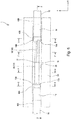
- Fig. 11 is a plan view showing an optical combiner structure 100 according to a second embodiment of the present invention.
- Fig. 12 is a cross-sectional view of the optical combiner structure 100 taken along line G-G shown in Fig. 11 .
- the optical combiner structure 100 further includes a heat dissipation resin 44A formed between the fixation resin 40A and the seal resin 42A so as to cover an outer circumference of the covering 13 and a heat dissipation resin 44B formed between the fixation resin 40B and the seal resin 42B so as to cover an outer circumference of the covering 14.
- the heat dissipation resin 44A is formed such that at least a portion of the heat dissipation resin 44A is brought into contact with the fixation resin 40A and the seal resin 42A
- the heat dissipation resin 44B is formed such that at least a portion of the heat dissipation resin 44B is brought into contact with the fixation resin 40B and the seal resin 42B.
- the heat dissipation resin 44A is spaced from the inner surface of the fiber accommodation groove 21.
- the heat dissipation resin 44B is also spaced from the inner surface of the fiber accommodation groove 21, which is not illustrated.
- Those heat dissipation resins 44A and 44B are formed of a material having a thermal conductivity higher than those of the claddings in the bare fibers 15 and 16 and the covering 13 and 14.
- At least a portion of the heat dissipation resins 44A and 44B are formed so as to be in contact with the seal resins 42A and 42B. Therefore, heat generated in the seal resins 42A and 42B by light propagating through the optical fibers 11 and 12 is likely to be transmitted through the heat dissipation resins 44A and 44B along the axial direction. Furthermore, at least a portion of the heat dissipation resins 44A and 44B is formed so as to be in contact with the fixation resins 40A and 40B. Therefore, heat transmitted through the heat dissipation resins 44A and 44B as described above is likely to be transmitted through the fixation resins 40A and 40B to the fiber accommodation portion 20. Thus, the external heat dissipation performance is improved.
- the heat dissipation resins 44A and 44B are formed so as to cover the entire regions ranging from the fixation resins 40A and 40B to the seal resins 42A and 42B.
- the heat dissipation resins 44A and 44B may be formed so as to cover a portion of those regions. Furthermore, only either one of the heat dissipation resins 44A and 44B may be provided.
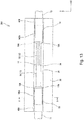
- Fig. 13 is a plan view showing an optical combiner structure 200 according to a third embodiment of the present invention.
- Fig. 14 is a cross-sectional view of the optical combiner structure 200, which corresponds to Fig. 12 .
- the optical combiner structure 200 has seal resins 342A and 342B, which are formed by extending the seal resins 42A and 42B of the optical combiner structure 1 to locations where the seal resins 42A and 42B are brought into contact with the fixation resins 40A and 40B.
- the seal resin 342A is spaced from the inner surface of the fiber accommodation groove 21.
- the seal resin 342B is also spaced from the inner surface of the fiber accommodation groove 21, which is not illustrated.
- Those seal resins 342A and 342B are formed of a material having a thermal conductivity higher than those of the claddings in the bare fibers 15 and 16 and the coverings 13 and 14.
- the seal resins 342A and 342B not only serve to seal a space between the bare fibers 15, 16 and the coverings 13, 14, but also serve as heat dissipation resins to dissipate heat of the optical fibers 11 and 12 to the exterior of the optical combiner structure 200 in the present embodiment. Therefore, according to the present embodiment, the seal resins and the heat dissipation resins can be formed of the same material.
- the seal resins 342A and 342B are spaced from the inner surface of the fiber accommodation groove 21, no microbend is caused to the optical fibers 11 and 12 for the aforementioned reasons even if the seal resins 342A and 342B are under a high-temperature environment.
- deterioration of the optical characteristics of the optical combiner 10 is prevented under a high-temperature environment.
- Fig. 15 is a view showing an optical combiner structure 400 according to a fourth embodiment of the present invention and is a cross-sectional view corresponding to Fig. 6 .
- the entire surface of the covering end face S1 formed between the end 13A of the covering 13 and the end 17A of the bare fiber exposure portion 17 and the entire surface of the covering end face 2 formed between the end 14A of the covering 14 and the end 18A of the bare fiber exposure portion 18 are covered with the seal resins 42A and 42B, respectively (see Fig. 6 ).
- the seal resins 442A and 442B only a portion of the covering end faces S1 and S2 is covered with the seal resins 442A and 442B.
- only portions of the covering end faces S1 and S2 near the bare fibers 15 and 16 are covered with the seal resins 442A and 442B.
- spaces between the bare fibers 15, 16 and the coverings 13, 14 are sealed.
- the optical combiner structure 400 is configured such that the seal resins 442A and 442Bd do not cover the entire covering end surfaces S1 and S2, but cover only a portion of the covering end surfaces S1 and S2. Therefore, the spaces between the bare fibers 15, 16 and the coverings 13, 14 can be sealed with a smaller amount of the seal resins as compared to the other embodiments. Therefore, a manufacturing cost can be reduced.
- the present invention may be applied to either one of the covering end faces S1 and S2.
- Figs. 16 , 17 , 18 , and 20A are plan views corresponding to Fig. 11
- Fig. 19 is a cross-sectional view taken along line H-H of Fig. 18
- Fig. 20B is a cross-sectional view corresponding to Fig. 6 .
- the covering 13 is peeled from an end of the first optical fiber 11 by a predetermined distance to form a bare fiber exposure portion 17.
- the covering 14 is peeled from an end of the second optical fiber 12 by a predetermined distance to form a bare fiber exposure portion 18.
- the bare fiber exposure portion 17 and the bare fiber exposure portion 18 are connected to each other by fusion splicing to form an optical combiner 10 having a fusion splice portion 19.
- a seal resin 42A is provided near the end 17A of the bare fiber exposure portion 17 that is located at the opposite side of the fusion splice portion 19 so as to cover a portion of the bare fiber exposure portion 17 and a portion of the covering 13. At that time, the seal resin 42A is formed so as to have such a thickness that the seal resin 42A does not reach an inner surface of the fiber accommodation groove 21 of the fiber accommodation portion 20.
- a seal resin 42B is provided near the end 18A of the bare fiber exposure portion 18 that is located at the opposite side of the fusion splice portion 19 so as to cover a portion of the bare fiber exposure portion 18 and a portion of the covering 14. At that time, the seal resin 42B is formed so as to have such a thickness that the seal resin 42B does not reach the inner surface of the fiber accommodation groove 21 of the fiber accommodation portion 20.
- a single seal resin may be formed so as to cover the entire length of the bare fiber exposure portions 17 and 18 with such a thickness that it does not reach the inner surface of the fiber accommodation groove 21.
- a heat dissipation resin 44A is provided on an outer circumference of the covering 13 so as to extend toward the opposite side of the fusion splice portion 19. At that time, the heat dissipation resin 44A is formed so as to have such a thickness that the heat dissipation resin 44A does not reach the inner surface of the fiber accommodation groove 21 of the fiber accommodation portion 20.
- the heat dissipation resin 44A may be formed so as to overlap with at least a portion of the seal resin 42A. Furthermore, the heat dissipation resin 44A may be formed so as to extend across the entire region ranging between the seal resin 42A and the fixation resin 40A.
- a heat dissipation resin 44B is provided on an outer circumference of the covering 14 so as to extend toward the opposite side of the fusion splice portion 19. At that time, the heat dissipation resin 44B is formed so as to have such a thickness that the heat dissipation resin 44B does not reach the inner surface of the fiber accommodation groove 21 of the fiber accommodation portion 20.
- the heat dissipation resin 44B may be formed so as to overlap with at least a portion of the seal resin 42B. Furthermore, the heat dissipation resin 44B may be formed so as to extend across the entire region ranging between the seal resin 42B and the fixation resin 40B.
- the seal resins 42A and 42B and the heat dissipation resins 44A and 44B are hardened.
- the seal resins 42A and 42B and the heat dissipation resins 44A and 44B are hardened before the optical fibers 11 and 12 are accommodated within the fiber accommodation groove 21.
- the seal resins 42A and 42B and the heat dissipation resins 44A and 44B isotropically shrink over the circumferential direction. Accordingly, microbend is prevented from being generated at portions where the seal resins 42A and 42B and the heat dissipation resins 44A and 44B have been provided in the optical fibers 11 and 12.
- the optical fibers 11 and 12 are received into the fiber accommodation groove 21 such that the seal resins 42A and 42B and the heat dissipation resins 44A and 44B are spaced from the inner surface of the fiber accommodation groove 21.
- the optical fibers 11 and 12 are held in the accommodated locations. While the seal resins 42A and 42B and the heat dissipation resins 44A and 44B are held in such a state in which they are spaced from the inner surface of the fiber accommodation groove 21, fixation resins 40A and 40B are filled into both ends of the fiber accommodation groove 21.
- the optical fibers 11 and 12 are fixed in the fiber accommodation groove 21.
- an optical combiner structure 100 is completed (see Fig. 11 ).
- the fixation resins 40A and 40B may be formed so as to overlap with at least a portion of the heat dissipation resins 44A and 44B.
- the seal resins 42A and 42B and the heat dissipation resins 44A and 44B are hardened before the optical fibers 11 and 12 are received into the fiber accommodation groove 21. That is, according to the present manufacturing method, the seal resins 42A and 42B and the heat dissipation resins 44A and 44B can be hardened so that they shrink isotropically over the circumferential direction. Accordingly, anisotropic stresses are prevented from being applied to the optical fibers 11 and 12 by those resins.
- the seal resins 42A and 42B and the heat dissipation resins 44A and 44B are formed of a material having a high rate of cure shrinkage, microbend is prevented from being generated at portions where those resins are provided (see Fig. 19 ).
- a material having a low refractive index can be selected as a material for the seal resins 42A and 42B.
- generation of microbend is prevented even if the seal resins are formed of a material having a low refractive index. Accordingly, deterioration of the optical characteristics of the optical combiner structure is mitigated during the manufacturing process, and an optical combiner structure having excellent optical characteristics can be provided.
- the bare fiber 15 of the first optical fiber 11 is formed so as to have such a large diameter that it is connected to all (seven) bare fibers of the second optical fiber 12.
- the bare fiber 15 of the first optical fiber 11 may not be subject to enormous influence of the aforementioned anisotropic stresses as compared to the small-diameter bare fibers of the second optical fiber 12.
- the seal resin 42A may not need to be formed so as to have such a thickness that it does not reach the inner surface of the fiber accommodation groove 21, and the seal resin 42A may be formed so as to have such a thickness that a portion of the seal resin 42A or the entire seal resin 42A is brought into contact with the inner surface of the fiber accommodation groove 21.
- an optical fiber protection structure according to the present invention is applicable to any optical element other than an optical combiner and a method of manufacturing such an optical element.
- the present invention is suitably used for an optical fiber protection structure that accommodates at least a portion of an optical fiber therein.
Landscapes
- Physics & Mathematics (AREA)
- General Physics & Mathematics (AREA)
- Optics & Photonics (AREA)
- Engineering & Computer Science (AREA)
- Plasma & Fusion (AREA)
- Chemical & Material Sciences (AREA)
- Crystallography & Structural Chemistry (AREA)
- Mechanical Coupling Of Light Guides (AREA)
- Optical Couplings Of Light Guides (AREA)
- Road Signs Or Road Markings (AREA)
Abstract
Description
- The present invention relates to an optical fiber protection structure and a method of manufacturing an optical element, and more particularly to an optical fiber protection structure that receives at least a portion of an optical fiber therein and an optical combiner structure using the same.
- For example, in many cases, optical fibers are connected to each other by removing coverings of the optical fibers and fusion-splicing bare fibers of the optical fibers to each other. Such portions of the optical fibers where the coverings have been removed are vulnerable to external forces and may be broken when any impact or vibration is exerted to those portions. In order to prevent such a problem, for example, an optical fiber protection structure as illustrated in
Patent Literature 1 may be applied.Fig. 1 is a plan view showing anoptical combiner structure 500 to which such a conventional optical fiber protection structure has been applied. As shown inFig. 1 , according to theoptical combiner structure 500, afusion splice portion 519 and barefiber exposure portions optical fibers fiber accommodation groove 521 of afiber accommodation portion 520, which has a high tensile strength. With such a structure, those portions are protected from external forces such as impact or vibration. - However,
portions fiber exposure portions coverings optical combiner structure 500. Therefore, moisture may be introduced fromsuch portions coverings optical fibers - In order to solve the aforementioned problems, for example, an optical fiber protection structure disclosed in
Patent Literature 2 may be applied.Fig. 2 is a plan view showing anoptical combiner structure 600 to which such a conventional optical fiber protection structure has been applied, andFigs. 3 and 4 are cross-sectional views of theoptical combiner structure 600 illustrated inFig. 2 , taken along line A-A. As shown inFig. 2 , theoptical combiner structure 600 includesoptical fibers fiber accommodation portion 620 in which afiber accommodation groove 621 is formed to receive a portion of theoptical fibers - As shown in
Figs. 2 to 4 , in theoptical combiner structure 600,resins fiber accommodation groove 621 where aboundary portion 617A between a barefiber exposure portion 617 and acovering 613 and aboundary portion 618A between a barefiber exposure portion 618 and a covering 614 are respectively located. Thus, theboundary portions fiber exposure portions coverings boundary portions optical combiner structure 600, moisture is prevented from being introduced from thoseportions resins optical fibers structure 600.Fig. 3 shows a state in which theresin 640A has swelled, andFig. 4 shows a state in which theresin 640A has shrunk. - Meanwhile, as shown in
Figs. 2 to 4 , when theresins fiber accommodation groove 621, they are brought into contact with right and left inner surfaces (opposed inner surfaces in the Y-direction) and a lower inner surface (in the -Z-direction) of thefiber accommodation groove 621. In contrast, upper sides (in the +Z-direction) of theresins resins optical fibers fiber accommodation groove 621 as indicated by arrows ofFig. 3 . On the other hand, since the upper sides of theresins fiber accommodation groove 621. In other words, anisotropic compressive stresses are applied to theoptical fibers resins resins optical fibers optical combiner structure 600 is applied, the optical characteristics of the optical fibers may problematically be deteriorated under a high-temperature environment. - Furthermore, when the
resins optical fibers fiber accommodation groove 621 as indicated by arrows ofFig. 4 . On the other hand, since the upper sides of theresins fiber accommodation groove 621. In other words, anisotropic tensile stresses are applied to theoptical fibers resins resins optical fibers optical combiner structure 600 is manufactured, the optical characteristics of the optical fibers may problematically be deteriorated. - In order to avoid the problem that the aforementioned anisotropic stresses may cause microbend to the optical fibers when the resins shrink by curing, the
resins resins optical fibers structure 600, then it is difficult to use a material having a low rate of cure shrinkage. In other words, theoptical combiner structure 600 has difficulties in solving both of problems to prevent generation of microbend and leakage of light. In this aspect, the optical characteristics of the optical fibers may problematically be deteriorated. -
- Patent Literature 1:
JP 2009-116076 A - Patent Literature 2:
JP 2005-202200 A - The present invention has been made in view of the above drawbacks of the prior art. It is, therefore, a first object of the present invention is to provide an optical fiber protection structure capable of mitigating deterioration of optical characteristics of an optical fiber under a high-temperature environment.
- Furthermore, a second object of the present invention is to provide a method of manufacturing an optical element that can avoid deterioration of optical characteristics.
- According to a first aspect of the present invention, there is provided an optical fiber protection structure capable of mitigating deterioration of optical characteristics of an optical fiber under a high-temperature environment. This optical fiber protection structure protects a bare fiber exposure portion in which a bare fiber is exposed from a covering of at least one optical fiber. The optical fiber protection structure has a fiber accommodation portion having a fiber accommodation groove that receives the bare fiber exposure portion therein, a fixation resin filled within the fiber accommodation groove for fixing a portion of the covering within the fiber accommodation groove, and two seal resins for sealing a space between the bare fiber and the covering on both ends of the bare fiber exposure portion. At least one of the two seal resins is formed so as to be spaced from an inner surface of the fiber accommodation groove.
- With this configuration, since two seal resins seal a space between the bare fiber and the covering on both ends of the bare fiber exposure portion, moisture is prevented from being introduced into the optical fiber from between the bare fiber and the covering. Furthermore, since at least one of the two seal resins is formed so as to be spaced from the inner surface of the fiber accommodation groove, the seal resin can expand isotropically. Accordingly, microbend is prevented from being generated in the optical fiber under a high-temperature environment. As a result, deterioration of the optical characteristics of the optical fiber is mitigated under a high-temperature environment.
- According to a second aspect of the present invention, there is provided an optical fiber protection structure capable of mitigating deterioration of optical characteristics of an optical fiber under a high-temperature environment. This optical fiber protection structure protects a bare fiber exposure portion in which a bare fiber is exposed from a covering of at least one optical fiber. The optical fiber protection structure has a fiber accommodation portion having a fiber accommodation groove that receives the bare fiber exposure portion therein, a fixation resin filled within the fiber accommodation groove for fixing a portion of the covering within the fiber accommodation groove, and a single seal resin for sealing a space between the bare fiber and the covering on both ends of the bare fiber exposure portion. The single seal resin is formed so as to be spaced from an inner surface of the fiber accommodation groove.
- With this configuration, since a single seal resin seals a space between the bare fiber and the covering on both ends of the bare fiber exposure portion, moisture is prevented from being introduced into the optical fiber from between the bare fiber and the covering. Furthermore, since the single seal resin is formed so as to be spaced from the inner surface of the fiber accommodation groove, the seal resin can expand isotropically. Accordingly, microbend is prevented from being generated in the optical fiber under a high-temperature environment. As a result, deterioration of the optical characteristics of the optical fiber is mitigated under a high-temperature environment.
- The seal resin may preferably have a refractive index lower than that of a cladding in the bare fiber. In this case, light propagating through the optical fiber is prevented from leaking out. Furthermore, the seal resin may have a thermal conductivity higher than those of a cladding in the bare fiber and the covering. In this case, heat generated by light propagating through the optical fiber is dissipated to an exterior of the optical combiner structure.
- Furthermore, the optical fiber protection structure may further include a heat dissipation resin having a thermal conductivity higher than those of a cladding in the bare fiber and the covering. The heat dissipation resin may cover an outer circumference of the covering located within the fiber accommodation groove. The heat dissipation resin is formed so as to be spaced from the inner surface of the fiber accommodation groove. Thus, heat generated by light propagating through the optical fiber is dissipated to an exterior of the optical combiner structure. In order to enhance the conductivity of heat generated by light propagating through the optical fiber, at least a portion of the heat dissipation resin may preferably be in contact with the seal resin. Furthermore, in order to improve dissipation of heat thus transmitted, at least a portion of the heat dissipation resin may preferably be in contact with the fixation resin.
- According to a third aspect of the present invention, there is provided a method that can manufacture an optical element while deterioration of optical characteristics is mitigated. This manufacturing method of an optical element is to manufacture an optical element using an optical fiber protection structure for protecting a bare fiber exposure portion in which a bare fiber is exposed from a covering of at least one optical fiber. According to the manufacturing method, two seal resins are first formed on both ends of the bare fiber exposure portion to seal a space between the bare fiber and the covering such that at least one of the two seal resins has such a thickness so as not to reach an inner surface of a fiber accommodation groove formed in a fiber accommodation portion when the bare fiber exposure portion is accommodated within the fiber accommodation groove. After the formation of the two seal resins, the bare fiber exposure portion is accommodated within the fiber accommodation groove of the fiber accommodation portion such that the at least one of the two seal resins is spaced from the inner surface of the fiber accommodation groove. Then a fixation resin is filled into the fiber accommodation groove to fix a portion of the covering accommodated in the fiber accommodation groove to the fiber accommodation groove to complete the optical element.
- In this manufacturing method, two seal resins are formed before the optical fiber is accommodated in the fiber accommodation groove. When the two seal resins are formed, they can shrink isotropically. Therefore, microbend is prevented from being generated in the optical fiber during the manufacturing process. As a result, deterioration of the optical characteristics of the optical fiber is mitigated at the manufacturing stage. Furthermore, since the seal resins can thus shrink isotropically, generation of microbend is suppressed even if the seal resins are formed of a material having a high rate of cure shrinkage. Therefore, the seal resins can be formed of a material having a low refractive index.
- According to a fourth aspect of the present invention, there is provided a method that can manufacture an optical element while deterioration of optical characteristics is mitigated. This manufacturing method of an optical element is to manufacture an optical element using an optical fiber protection structure for protecting a bare fiber exposure portion in which a bare fiber is exposed from a covering of at least one optical fiber. According to the manufacturing method, a single seal resin is first formed to seal a space between the bare fiber and the covering on both ends of the bare fiber exposure portion such that the single seal resin has such a thickness so as not to reach an inner surface of a fiber accommodation groove formed in a fiber accommodation portion when the bare fiber exposure portion is accommodated within the fiber accommodation groove. After the formation of the single seal resin, the bare fiber exposure portion is accommodated within the fiber accommodation groove of the fiber accommodation portion such that the single seal resin is spaced from the inner surface of the fiber accommodation groove. A fixation resin is filled into the fiber accommodation groove to fix a portion of the covering accommodated in the fiber accommodation groove to the fiber accommodation groove to complete the optical element.
- In this manufacturing method, a single seal resin is formed before the optical fiber is accommodated in the fiber accommodation groove. When the single seal resin is formed, it can shrink isotropically. Therefore, microbend is prevented from being generated in the optical fiber during the manufacturing process. As a result, deterioration of the optical characteristics of the optical fiber is mitigated at the manufacturing stage. Furthermore, since the seal resin can thus shrink isotropically, generation of microbend is suppressed even if the seal resin is formed of a material having a high rate of cure shrinkage. Therefore, the seal resin can be formed of a material having a low refractive index.
- Before the bare fiber exposure portion is accommodated within the fiber accommodation groove, a heat dissipation resin having a thermal conductivity higher than those of a cladding in the bare fiber and the covering may be formed on an outer circumference of the covering such that the heat dissipation resin has such a thickness so as not to reach the inner surface of the fiber accommodation groove when the bare fiber exposure portion is accommodated within the fiber accommodation groove. When the bare fiber exposure portion is accommodated within the fiber accommodation groove, the seal resin and the heat dissipation resin may be spaced from the inner surface of the fiber accommodation groove. This configuration can produce an optical element that can dissipate heat generated by light propagating through the optical fiber to an exterior of the optical combiner structure.
- According to an optical fiber protection structure of the first aspect of the present invention, since at least one of the two seal resins is formed so as to be spaced from the inner surface of the fiber accommodation groove, the seal resin can expand isotropically. Therefore, microbend is prevented from being generated in the optical fiber under a high-temperature environment. As a result, deterioration of the optical characteristics of the optical fiber is mitigated under a high-temperature environment.
- According to an optical fiber protection structure of the second aspect of the present invention, since the single seal resin is formed so as to be spaced from the inner surface of the fiber accommodation groove, the seal resin can expand isotropically. Therefore, microbend is prevented from being generated in the optical fiber under a high-temperature environment. As a result, deterioration of the optical characteristics of the optical fiber is mitigated under a high-temperature environment.
- Furthermore, according to a manufacturing method of an optical element of the third aspect of the present invention, two seal resins can be formed before the optical fiber is accommodated in the fiber accommodation groove. Therefore, microbend is prevented from being generated in the optical fiber during the manufacturing process. As a result, deterioration of the optical characteristics of the optical fiber is mitigated at the manufacturing stage, and the seal resins can be formed of a material having a low refractive index.
- Moreover, according to a manufacturing method of an optical element of the fourth aspect of the present invention, a single seal resin can be formed before the optical fiber is accommodated in the fiber accommodation groove. Therefore, microbend is prevented from being generated in the optical fiber during the manufacturing stage. As a result, deterioration of the optical characteristics of the optical fiber is mitigated at the manufacturing stage, and the seal resin can be formed of a material having a low refractive index.
-
-
Fig. 1 is a plan view schematically showing a conventional optical fiber protection structure. -
Fig. 2 is a plan view schematically showing a conventional optical fiber protection structure. -
Fig. 3 is a cross-sectional view taken along line A-A ofFig. 2 , schematically showing a state in which a resin has expanded. -
Fig. 4 is a cross-sectional view taken along line A-A ofFig. 2 , schematically showing a state in which a resin has shrunk. -
Fig. 5 is a plan view showing an optical combiner structure according to a first embodiment of the present invention. -
Fig. 6 is a cross-sectional view of the optical combiner structure taken along line B-B ofFig. 5 . -
Fig. 7 is a cross-sectional view taken along line C-C ofFig. 5 . -
Fig. 8 is a cross-sectional view taken along line D-D ofFig. 5 . -
Fig. 9 is a cross-sectional view taken along line E-E ofFig. 5 . -
Fig. 10 is a cross-sectional view taken along line F-F ofFig. 5 . -
Fig. 11 is a plan view showing an optical combiner structure according to a second embodiment of the present invention. -
Fig. 12 is a cross-sectional view taken along line G-G ofFig. 11 . -
Fig. 13 is a plan view showing an optical combiner structure according to a third embodiment of the present invention. -
Fig. 14 is a cross-sectional view showing the optical combiner structure according to the third embodiment of the present invention, which corresponds toFig. 12 . -
Fig. 15 is a diagram showing an optical combiner structure according to a fourth embodiment of the present invention and is a cross-sectional view corresponding toFig. 6 . -
Fig. 16 is a diagram illustrating an example of a method of manufacturing an optical combiner structure according to the second embodiment of the present invention. -
Fig. 17 is a diagram illustrating an example of a method of manufacturing the optical combiner structure according to the second embodiment of the present invention. -
Fig. 18 is a diagram illustrating an example of a method of manufacturing the optical combiner structure according to the second embodiment of the present invention. -
Fig. 19 is a diagram illustrating an example of a method of manufacturing the optical combiner structure according to the second embodiment of the present invention and is a cross-sectional view taken along line H-H ofFig. 18 . -
Fig. 20A is a diagram illustrating an example of a method of manufacturing the optical combiner structure according to the second embodiment of the present invention. -
Fig. 20B is a diagram illustrating an example of a method of manufacturing the optical combiner structure according to the second embodiment of the present invention and is a cross-sectional view corresponding toFig. 6 . - Embodiments of an optical fiber protection structure and an optical combiner structure using such an optical fiber protection structure according to the present invention will be described in detail below with reference to
Figs. 5 to 20B . InFigs. 5 to 20B , the same or corresponding components are denoted by the same or corresponding reference numerals and will not be described below repetitively. Furthermore, inFigs. 5 to 20B , the scales or dimensions of components may be exaggerated, or some components may be omitted. -
Fig. 5 is a plan view showing anoptical combiner structure 1 according to a first embodiment of the present invention, andFig. 6 is a cross-sectional view taken along line B-B ofFig. 5 . As shown inFigs. 5 and6 , theoptical combiner structure 1 includes anoptical combiner 10 havingoptical fibers fiber accommodation portion 20 that protects afusion splice portion 19 between theoptical fibers optical combiner 10 has a firstoptical fiber 11, a secondoptical fiber 12, and afusion splice portion 19 at which the firstoptical fiber 11 and the secondoptical fiber 12 are connected to each other by fusion splicing. Thefiber accommodation portion 20 serves to protect theoptical fibers fusion splice portion 19 from external forces, impact, and vibration. -
Fig. 7 is a cross-sectional view taken along line C-C ofFig. 5 , andFig. 8 is a cross-sectional view taken along line D-D ofFig. 5 . As shown inFigs. 5 to 8 , thefiber accommodation portion 20 is in the form of a generally rectangular parallelepiped with a longitudinal direction along the X-direction. Afiber accommodation groove 21 extending along the X-direction is formed in anupper surface 20A of thefiber accommodation portion 20. - As shown in
Figs. 5 and6 , a covering 13 of the firstoptical fiber 11 is removed over a predetermined distance from an end of the firstoptical fiber 11. Thus, a barefiber exposure portion 17 in which abare fiber 15 is exposed is formed. Furthermore, a covering 14 of the secondoptical fiber 12 is removed over a predetermined distance from an end of the secondoptical fiber 12. Thus, a barefiber exposure portion 18 in which abare fiber 16 is exposed is formed. The barefiber exposure portion 17 of the firstoptical fiber 11 and the barefiber exposure portion 18 of the secondoptical fiber 12 are connected to each other at thefusion splice portion 19 by fusion splicing. - The bare
fiber exposure portion 17 of the firstoptical fiber 11 and the barefiber exposure portion 18 of the secondoptical fiber 12 are disposed within thefiber accommodation groove 21 of thefiber accommodation portion 20 in a state in which the barefiber exposure portion 17 and the barefiber exposure portion 18 are connected to each other at thefusion splice portion 19 by fusion splicing. With such a configuration, thefusion splice portion 19 and the barefiber exposure portions fiber accommodation groove 21 of thefiber accommodation portion 20. For example, thefiber accommodation portion 20 may be formed of a glass material such as Neoceram (trademark) or quartz. - In the present embodiment, the first
optical fiber 11 is formed by a single fiber having acore 11A (seeFig. 7 ), and the secondoptical fiber 12 is formed by a bundle fiber into which a plurality of optical fibers (seven optical fibers in the illustrated example) each having a core 12A are bundled (seeFig. 8 ). Thus, theoptical combiner 10 of the present embodiment is formed as a 7 × 1 combiner. As a matter of course, the number of the core 11A of the firstoptical fiber 11 and the number of thecores 12A of the secondoptical fiber 12 may be changed in an appropriate manner. - As shown in
Figs. 6 and7 , the firstoptical fiber 11 is fixed within thefiber accommodation groove 21 by afixation resin 40A, which is filled into a first end of thefiber accommodation groove 21 along the X-direction. As shown inFig. 7 , thisfixation resin 40A surrounds the whole circumference of the covering 13 of the firstoptical fiber 11. Similarly, as shown inFigs. 6 and7 , the secondoptical fiber 12 is fixed within thefiber accommodation groove 21 by afixation resin 40B, which is filled into a second end of thefiber accommodation groove 21 along the X-direction. As shown inFig. 8 , thisfixation resin 40B also surrounds the whole circumference of the covering 14 of the secondoptical fiber 12. - As described above, the bare
fiber exposure portions fusion splice portion 19 of theoptical fibers fiber accommodation groove 21 of thefiber accommodation portion 20. Therefore, the barefiber exposure portions fusion splice portion 19 of theoptical fibers fiber accommodation portion 20 serves as a protection structure for theoptical combiner 10 having theoptical fibers fusion splice portion 19. - As shown in
Figs. 5 and6 , aseal resin 42A is provided near anend 17A of the barefiber exposure portion 17 that is located on an opposite side of thefusion splice portion 19. Theseal resin 42A covers a portion of the barefiber exposure portion 17 and a portion of thecovering 13.Fig. 9 is a cross-sectional view taken along line E-E ofFig. 5 . As shown inFigs. 7 and9 , theseal resin 42A covers the whole circumferences of thebare fiber 15 and the covering 13 near theend 17A. With such a configuration, a space between thebare fiber 15 and the covering 13 at theend 17A is sealed by theseal resin 42A. - Similarly, as shown in
Figs. 5 and6 , aseal resin 42B is provided near anend 18A of the barefiber exposure portion 18 that is located on an opposite side of thefusion splice portion 19. Theseal resin 42B covers a portion of the barefiber exposure portion 18 and a portion of thecovering 14.Fig. 10 is a cross-sectional view taken along line F-F ofFig. 5 . As shown inFigs. 7 and10 , theseal resin 42B covers the whole circumferences of thebare fiber 16 and the covering 14 near theend 18A. With such a configuration, a space between thebare fiber 16 and the covering 14 at theend 18A is sealed by theseal resin 42B. - Thus, in the present embodiment, the space between the
end 17A of the barefiber exposure portion 17 and the covering 13 and the space between theend 18A of the barefiber exposure portion 18 and the covering 14 are sealed by the seal resins 42A. Therefore, moisture is prevented from being introduced between theends coverings coverings optical combiner 10 is mitigated. - Referring again to
Figs. 5 and6 , theaforementioned seal resin 42A is spaced from an inner surface of thefiber accommodation groove 21. Similarly, theseal resin 42B is spaced from the inner surface of thefiber accommodation groove 21. In other words, the seal resins 42A and 42B are provided within thefiber accommodation groove 21 such that they are out of contact with the inner surface of thefiber accommodation groove 21. - With such an arrangement, even if the
optical combiner structure 1 is under a high-temperature environment, the seal resins 42A and 42B can expand isotropically over a circumferential direction without any inhibition by the inner surface of thefiber accommodation groove 21. Therefore, no anisotropic stresses are applied to the seal resins 42A and 42B by the inner surface of thefiber accommodation groove 21 when the seal resins 42A and 42B expand. Accordingly, microbend is prevented from being generated at portions of theoptical fibers optical combiner 10 is mitigated under a high-temperature environment. - As shown in
Fig. 6 , in the present embodiment, theseal resin 42A is provided to seal the space between thebare fiber 15 and the covering 13 at theend 17A, and theseal resin 42B is provided to seal the space between thebare fiber 16 and the covering 14 at theend 18A. A single seal resin may be provided so as to cover the entire length of the barefiber exposure portions fiber accommodation groove 21. This single seal resin may seal the space between thebare fiber 15 and the covering 13 at theend 17A and the space between thebare fiber 16 and the covering 14 at theend 18A. - As shown in
Fig. 5 , thebare fiber 15 of the firstoptical fiber 11 is formed so as to have such a large diameter that it is connected to all (seven) bare fibers of the secondoptical fiber 12. Thus, thebare fiber 15 of the firstoptical fiber 11 may not be subject to enormous influence of the aforementioned anisotropic stresses as compared to the small-diameter bare fibers of the secondoptical fiber 12. In such a case, therefore, theseal resin 42A may not necessarily be spaced from the inner surface of thefiber accommodation groove 21, and a portion of theseal resin 42A or theentire seal resin 42A may be brought into contact with the inner surface of thefiber accommodation groove 21. - It is preferable to form
such seal resins bare fibers optical combiner 10 from leaking out (particularly from the vicinity of theends -
Fig. 11 is a plan view showing anoptical combiner structure 100 according to a second embodiment of the present invention.Fig. 12 is a cross-sectional view of theoptical combiner structure 100 taken along line G-G shown inFig. 11 . As shown inFig. 11 , theoptical combiner structure 100 further includes aheat dissipation resin 44A formed between thefixation resin 40A and theseal resin 42A so as to cover an outer circumference of the covering 13 and aheat dissipation resin 44B formed between thefixation resin 40B and theseal resin 42B so as to cover an outer circumference of thecovering 14. In the present embodiment, theheat dissipation resin 44A is formed such that at least a portion of theheat dissipation resin 44A is brought into contact with thefixation resin 40A and theseal resin 42A, and theheat dissipation resin 44B is formed such that at least a portion of theheat dissipation resin 44B is brought into contact with thefixation resin 40B and theseal resin 42B. - As shown in
Fig. 12 , theheat dissipation resin 44A is spaced from the inner surface of thefiber accommodation groove 21. Similarly, theheat dissipation resin 44B is also spaced from the inner surface of thefiber accommodation groove 21, which is not illustrated. Thoseheat dissipation resins bare fibers - With such a configuration, heat generated by light propagating through the
optical fibers optical combiner structure 100 via theheat dissipation resins heat dissipation resins fiber accommodation groove 21, no microbend is caused to theoptical fibers heat dissipation resins optical combiner 10 is prevented under a high-temperature environment. - Particularly, in the present embodiment, at least a portion of the
heat dissipation resins optical fibers heat dissipation resins heat dissipation resins fixation resins heat dissipation resins fixation resins fiber accommodation portion 20. Thus, the external heat dissipation performance is improved. - In the present embodiment, the
heat dissipation resins fixation resins heat dissipation resins heat dissipation resins -
Fig. 13 is a plan view showing anoptical combiner structure 200 according to a third embodiment of the present invention.Fig. 14 is a cross-sectional view of theoptical combiner structure 200, which corresponds toFig. 12 . As shown inFig. 13 , theoptical combiner structure 200 hasseal resins optical combiner structure 1 to locations where the seal resins 42A and 42B are brought into contact with thefixation resins Fig. 14 , theseal resin 342A is spaced from the inner surface of thefiber accommodation groove 21. Similarly, theseal resin 342B is also spaced from the inner surface of thefiber accommodation groove 21, which is not illustrated. Thoseseal resins bare fibers coverings - With such a configuration, heat generated by light propagating through the
optical fibers optical combiner structure 200 via the seal resins 342A and 342B. As a result, increase of the temperature in the optical fibers is suppressed. In other words, the seal resins 342A and 342B not only serve to seal a space between thebare fibers coverings optical fibers optical combiner structure 200 in the present embodiment. Therefore, according to the present embodiment, the seal resins and the heat dissipation resins can be formed of the same material. Accordingly, a manufacturing process can be simplified, and a manufacturing cost can be reduced. Furthermore, since the seal resins 342A and 342B are spaced from the inner surface of thefiber accommodation groove 21, no microbend is caused to theoptical fibers optical combiner 10 is prevented under a high-temperature environment. -
Fig. 15 is a view showing anoptical combiner structure 400 according to a fourth embodiment of the present invention and is a cross-sectional view corresponding toFig. 6 . In the aforementioned other embodiments, the entire surface of the covering end face S1 formed between theend 13A of the covering 13 and theend 17A of the barefiber exposure portion 17 and the entire surface of the coveringend face 2 formed between theend 14A of the covering 14 and theend 18A of the barefiber exposure portion 18 are covered with the seal resins 42A and 42B, respectively (seeFig. 6 ). Meanwhile, in the present embodiment, only a portion of the covering end faces S1 and S2 is covered with the seal resins 442A and 442B. In other words, only portions of the covering end faces S1 and S2 near thebare fibers bare fibers coverings - In this manner, the
optical combiner structure 400 is configured such that the seal resins 442A and 442Bd do not cover the entire covering end surfaces S1 and S2, but cover only a portion of the covering end surfaces S1 and S2. Therefore, the spaces between thebare fibers coverings - Next, an example of a method of manufacturing an
optical combiner structure 100 according to the second embodiment of the present invention will be described with reference toFig. 11 andFigs. 16 to 20B .Figs. 16 ,17 ,18 , and20A are plan views corresponding toFig. 11 ,Fig. 19 is a cross-sectional view taken along line H-H ofFig. 18 , andFig. 20B is a cross-sectional view corresponding toFig. 6 . - First, the covering 13 is peeled from an end of the first
optical fiber 11 by a predetermined distance to form a barefiber exposure portion 17. Similarly, the covering 14 is peeled from an end of the secondoptical fiber 12 by a predetermined distance to form a barefiber exposure portion 18. As shown inFig. 16 , the barefiber exposure portion 17 and the barefiber exposure portion 18 are connected to each other by fusion splicing to form anoptical combiner 10 having afusion splice portion 19. - Then, as shown in
Fig. 17 , aseal resin 42A is provided near theend 17A of the barefiber exposure portion 17 that is located at the opposite side of thefusion splice portion 19 so as to cover a portion of the barefiber exposure portion 17 and a portion of thecovering 13. At that time, theseal resin 42A is formed so as to have such a thickness that theseal resin 42A does not reach an inner surface of thefiber accommodation groove 21 of thefiber accommodation portion 20. Similarly, aseal resin 42B is provided near theend 18A of the barefiber exposure portion 18 that is located at the opposite side of thefusion splice portion 19 so as to cover a portion of the barefiber exposure portion 18 and a portion of thecovering 14. At that time, theseal resin 42B is formed so as to have such a thickness that theseal resin 42B does not reach the inner surface of thefiber accommodation groove 21 of thefiber accommodation portion 20. - Instead of the seal resins 42A and 42B, a single seal resin may be formed so as to cover the entire length of the bare
fiber exposure portions fiber accommodation groove 21. - Furthermore, as shown in
Fig. 18 , aheat dissipation resin 44A is provided on an outer circumference of the covering 13 so as to extend toward the opposite side of thefusion splice portion 19. At that time, theheat dissipation resin 44A is formed so as to have such a thickness that theheat dissipation resin 44A does not reach the inner surface of thefiber accommodation groove 21 of thefiber accommodation portion 20. Theheat dissipation resin 44A may be formed so as to overlap with at least a portion of theseal resin 42A. Furthermore, theheat dissipation resin 44A may be formed so as to extend across the entire region ranging between theseal resin 42A and thefixation resin 40A. Similarly, aheat dissipation resin 44B is provided on an outer circumference of the covering 14 so as to extend toward the opposite side of thefusion splice portion 19. At that time, theheat dissipation resin 44B is formed so as to have such a thickness that theheat dissipation resin 44B does not reach the inner surface of thefiber accommodation groove 21 of thefiber accommodation portion 20. Theheat dissipation resin 44B may be formed so as to overlap with at least a portion of theseal resin 42B. Furthermore, theheat dissipation resin 44B may be formed so as to extend across the entire region ranging between theseal resin 42B and thefixation resin 40B. - When no
heat dissipation resins optical combiner structure 1 according to the first embodiment is manufactured, the process illustrated inFig. 18 does not need to be performed. - After the seal resins 42A and 42B and the
heat dissipation resins optical combiner 10, the seal resins 42A and 42B and theheat dissipation resins heat dissipation resins optical fibers fiber accommodation groove 21. Thus, as shown inFig. 19 , the seal resins 42A and 42B and theheat dissipation resins heat dissipation resins optical fibers - After the seal resins 42A and 42B and the
heat dissipation resins Figs. 20A and20B , theoptical fibers fiber accommodation groove 21 such that the seal resins 42A and 42B and theheat dissipation resins fiber accommodation groove 21. Theoptical fibers heat dissipation resins fiber accommodation groove 21,fixation resins fiber accommodation groove 21. Thus, theoptical fibers 11 and 12 (the optical combiner 10) are fixed in thefiber accommodation groove 21. In this manner, anoptical combiner structure 100 is completed (seeFig. 11 ). At that time, thefixation resins heat dissipation resins - As described above, according to the present manufacturing method, the seal resins 42A and 42B and the
heat dissipation resins optical fibers fiber accommodation groove 21. That is, according to the present manufacturing method, the seal resins 42A and 42B and theheat dissipation resins optical fibers heat dissipation resins Fig. 19 ). As a result, a material having a low refractive index can be selected as a material for the seal resins 42A and 42B. As described above, according to the present manufacturing method, generation of microbend is prevented even if the seal resins are formed of a material having a low refractive index. Accordingly, deterioration of the optical characteristics of the optical combiner structure is mitigated during the manufacturing process, and an optical combiner structure having excellent optical characteristics can be provided. - As described above, the
bare fiber 15 of the firstoptical fiber 11 is formed so as to have such a large diameter that it is connected to all (seven) bare fibers of the secondoptical fiber 12. Thus, thebare fiber 15 of the firstoptical fiber 11 may not be subject to enormous influence of the aforementioned anisotropic stresses as compared to the small-diameter bare fibers of the secondoptical fiber 12. In such a case, therefore, theseal resin 42A may not need to be formed so as to have such a thickness that it does not reach the inner surface of thefiber accommodation groove 21, and theseal resin 42A may be formed so as to have such a thickness that a portion of theseal resin 42A or theentire seal resin 42A is brought into contact with the inner surface of thefiber accommodation groove 21. - The terms "left," "right," "up," "down," "lower," and "upper," and other positional terms used herein are used in connection with the illustrated embodiments and may be varied depending on the relative positional relationship between components of the apparatus.
- Although some preferred embodiments of the present invention have been described, the present invention is not limited to the aforementioned embodiments. It should be understood that various different forms may be applied to the present invention within the technical idea thereof.
- The aforementioned embodiments exemplarily describe an optical combiner structure using an optical fiber protection structure according to the present invention and a method of manufacturing such an optical combiner structure. As a matter of course, however, an optical fiber protection structure according to the present invention is applicable to any optical element other than an optical combiner and a method of manufacturing such an optical element.
- The present invention is suitably used for an optical fiber protection structure that accommodates at least a portion of an optical fiber therein.
-
- 1, 100, 200, 400
- Optical combiner structure
- 10
- Optical combiner
- 11
- First optical fiber
- 11A, 12A
- Core
- 12
- Second optical fiber
- 13, 14
- Covering
- 13A, 14A, 17A, 18A
- End
- 15, 16
- Bare fiber
- 17, 18
- Bare fiber exposure portion
- 19
- Fusion splice portion
- 20
- Fiber accommodation portion
- 21
- Fiber accommodation groove
- 20A
- Upper surface
- 40A, 40B
- Fixation resin
- 42A, 42B, 342A, 342B, 442A, 442B
- Seal resin
- 44A, 44B
- Heat dissipation resin
- S1, S2
- Covering end face
Claims (10)
- An optical fiber protection structure for protecting a bare fiber exposure portion in which a bare fiber is exposed from a covering of at least one optical fiber, the optical fiber protection structure comprising:a fiber accommodation portion having a fiber accommodation groove that receives the bare fiber exposure portion therein;a fixation resin filled within the fiber accommodation groove for fixing a portion of the covering within the fiber accommodation groove; andtwo seal resins for sealing a space between the bare fiber and the covering on both ends of the bare fiber exposure portion,wherein at least one of the two seal resins is formed so as to be spaced from an inner surface of the fiber accommodation groove.
- An optical fiber protection structure for protecting a bare fiber exposure portion in which a bare fiber is exposed from a covering of at least one optical fiber, the optical fiber protection structure comprising:a fiber accommodation portion having a fiber accommodation groove that receives the bare fiber exposure portion therein;a fixation resin filled within the fiber accommodation groove for fixing a portion of the covering within the fiber accommodation groove; anda single seal resin for sealing a space between the bare fiber and the covering on both ends of the bare fiber exposure portion, the single seal resin being formed so as to be spaced from an inner surface of the fiber accommodation groove.
- The optical fiber protection structure as recited in claim 1 or 2, wherein the seal resin has a refractive index lower than that of a cladding in the bare fiber.
- The optical fiber protection structure as recited in claim 1 or 2, wherein the seal resin has a thermal conductivity higher than those of a cladding in the bare fiber and the covering.
- The optical fiber protection structure as recited in any one of claims 1 to 4, further comprising a heat dissipation resin having a thermal conductivity higher than those of a cladding in the bare fiber and the covering, the heat dissipation resin covering an outer circumference of the covering located within the fiber accommodation groove,
wherein the heat dissipation resin is formed so as to be spaced from the inner surface of the fiber accommodation groove. - The optical fiber protection structure as recited in claim 5, wherein at least a portion of the heat dissipation resin is in contact with the seal resin.
- The optical fiber protection structure as recited in claim 5 or 6, wherein at least a portion of the heat dissipation resin is in contact with the fixation resin.
- A method of manufacturing an optical element using an optical fiber protection structure for protecting a bare fiber exposure portion in which a bare fiber is exposed from a covering of at least one optical fiber, the method comprising:forming two seal resins on both ends of the bare fiber exposure portion to seal a space between the bare fiber and the covering such that at least one of the two seal resins has such a thickness so as not to reach an inner surface of a fiber accommodation groove formed in a fiber accommodation portion when the bare fiber exposure portion is accommodated within the fiber accommodation groove;after the forming the two seal resins, accommodating the bare fiber exposure portion within the fiber accommodation groove of the fiber accommodation portion such that the at least one of the two seal resins is spaced from the inner surface of the fiber accommodation groove; andfilling a fixation resin into the fiber accommodation groove to fix a portion of the covering accommodated in the fiber accommodation groove to the fiber accommodation groove.
- A method of manufacturing an optical element using an optical fiber protection structure for protecting a bare fiber exposure portion in which a bare fiber is exposed from a covering of at least one optical fiber, the method comprising:forming a single seal resin to seal a space between the bare fiber and the covering on both ends of the bare fiber exposure portion such that the single seal resin has such a thickness so as not to reach an inner surface of a fiber accommodation groove formed in a fiber accommodation portion when the bare fiber exposure portion is accommodated within the fiber accommodation groove;after the forming the single seal resin, accommodating the bare fiber exposure portion within the fiber accommodation groove of the fiber accommodation portion such that the single seal resin is spaced from the inner surface of the fiber accommodation groove; andfilling a fixation resin into the fiber accommodation groove to fix a portion of the covering accommodated in the fiber accommodation groove to the fiber accommodation groove.
- The method of manufacturing an optical element as recited in claim 8 or 9, further comprising, before the accommodating the bare fiber exposure portion within the fiber accommodation groove, forming on an outer circumference of the covering a heat dissipation resin having a thermal conductivity higher than those of a cladding in the bare fiber and the covering such that the heat dissipation resin has such a thickness so as not to reach the inner surface of the fiber accommodation groove when the bare fiber exposure portion is accommodated within the fiber accommodation groove,
wherein the accommodating the bare fiber exposure portion within the fiber accommodation groove comprises accommodating the bare fiber exposure portion within the fiber accommodation groove such that the seal resin and the heat dissipation resin are spaced from the inner surface of the fiber accommodation groove.
Applications Claiming Priority (2)
| Application Number | Priority Date | Filing Date | Title |
|---|---|---|---|
| JP2016082515A JP6368734B2 (en) | 2016-04-15 | 2016-04-15 | Optical fiber protection structure and optical element manufacturing method |
| PCT/JP2017/006298 WO2017179299A1 (en) | 2016-04-15 | 2017-02-21 | Optical fiber protection structure and method for producing optical element |
Publications (2)
| Publication Number | Publication Date |
|---|---|
| EP3444647A1 true EP3444647A1 (en) | 2019-02-20 |
| EP3444647A4 EP3444647A4 (en) | 2019-12-18 |
Family
ID=60041793
Family Applications (1)
| Application Number | Title | Priority Date | Filing Date |
|---|---|---|---|
| EP17782117.0A Withdrawn EP3444647A4 (en) | 2016-04-15 | 2017-02-21 | Optical fiber protection structure and method for producing optical element |
Country Status (5)
| Country | Link |
|---|---|
| US (1) | US11061189B2 (en) |
| EP (1) | EP3444647A4 (en) |
| JP (1) | JP6368734B2 (en) |
| CN (1) | CN109073831B (en) |
| WO (1) | WO2017179299A1 (en) |
Families Citing this family (9)
| Publication number | Priority date | Publication date | Assignee | Title |
|---|---|---|---|---|
| JP7134828B2 (en) * | 2018-10-12 | 2022-09-12 | 株式会社フジクラ | Optical device and laser device |
| JP6814776B2 (en) * | 2018-10-12 | 2021-01-20 | 株式会社フジクラ | Optical devices and laser devices |
| JPWO2020171058A1 (en) | 2019-02-21 | 2021-10-21 | 株式会社フジクラ | Optical fiber fixed structure, laser transmission cable using optical fiber fixed structure, and laser device |
| US11086075B2 (en) * | 2019-10-30 | 2021-08-10 | Alliance Fiber Optic Products, Inc. | Fiber array units with mode-field diameter conversion, and fabrication method |
| JP2021096370A (en) * | 2019-12-17 | 2021-06-24 | 株式会社フジクラ | Beam quality controlling device and laser device using the same |
| JP7391710B2 (en) * | 2020-02-17 | 2023-12-05 | 株式会社フジクラ | Fiber structures, optical combiners, laser light sources and laser devices |
| US20230056098A1 (en) * | 2020-02-17 | 2023-02-23 | Fujikura Ltd. | Fiber structure, optical combiner, laser light source, and laser device |
| CN114236693B (en) * | 2021-12-31 | 2024-06-04 | 合肥正阳光电科技有限责任公司 | Suspension type micro optical cable rapid connection connector and connection method |
| TWI913549B (en) | 2023-06-08 | 2026-02-01 | 萊凌科技股份有限公司 | Heat dissipation method and structure thereof for optical fiber element in vacuum environment |
Family Cites Families (22)
| Publication number | Priority date | Publication date | Assignee | Title |
|---|---|---|---|---|
| JPS6122004U (en) * | 1984-07-13 | 1986-02-08 | 昭和電線電纜株式会社 | Optical fiber protrusion prevention tool |
| JP3136741B2 (en) * | 1992-02-07 | 2001-02-19 | 住友電気工業株式会社 | Optical fiber reinforcement method |
| JPH05264848A (en) * | 1992-03-19 | 1993-10-15 | Sumitomo Electric Ind Ltd | Method for reinforcing optical fiber juncture |
| JPH08122553A (en) * | 1994-10-20 | 1996-05-17 | Japan Aviation Electron Ind Ltd | Fixing device for optical fiber fusion part |
| JPH09211250A (en) | 1996-01-31 | 1997-08-15 | Hoya Corp | Optical fiber connector and its manufacture |
| KR100219710B1 (en) * | 1996-07-30 | 1999-09-01 | 윤종용 | Metal coating optical fiber connecting method |
| CN1270322A (en) * | 2000-05-18 | 2000-10-18 | 林棱 | Multi-unit fused optical fibre coupler, its making method and equipment for implementing the method |
| JP4134499B2 (en) * | 2000-08-07 | 2008-08-20 | 住友電気工業株式会社 | Optical device |
| JP3699363B2 (en) * | 2001-05-15 | 2005-09-28 | Tdk株式会社 | Optical waveguide module mounting components |
| JP4100966B2 (en) * | 2002-06-04 | 2008-06-11 | 古河電気工業株式会社 | Fusion splicing method of optical fiber |
| JP2004069955A (en) * | 2002-08-06 | 2004-03-04 | Fuji Xerox Co Ltd | Method for manufacturing macromolecular optical waveguide |
| JP2005202200A (en) * | 2004-01-16 | 2005-07-28 | Fujikura Ltd | Optical fiber collimator and optical components |
| JP2006039273A (en) * | 2004-07-28 | 2006-02-09 | Kyocera Corp | Hermetic sealing structure of optical fiber mounting part |
| JP5124225B2 (en) * | 2007-05-15 | 2013-01-23 | 株式会社フジクラ | Optical fiber fusion splicing structure |
| JP2009116076A (en) | 2007-11-07 | 2009-05-28 | Mitsubishi Electric Corp | Optical fiber fused part holding structure |
| JP2011525706A (en) * | 2008-06-25 | 2011-09-22 | コラクティヴ ハイ−テック インコーポレイティド | Energy dissipation package for high power optical fiber components |
| JP5151953B2 (en) * | 2008-12-12 | 2013-02-27 | 住友電気工業株式会社 | Manufacturing method of optical module |
| JP5265025B2 (en) * | 2010-01-06 | 2013-08-14 | 株式会社フジクラ | Optical coupling structure and optical transceiver module |
| CN101852894B (en) * | 2010-04-29 | 2012-08-22 | 哈尔滨工程大学 | Coupling method for suspended-core optical fibers |
| JP5750997B2 (en) * | 2010-05-17 | 2015-07-22 | 住友電気工業株式会社 | Optical connector module |
| JP5790942B2 (en) * | 2012-06-22 | 2015-10-07 | 住友電気工業株式会社 | Optical fiber |
| CN104965259A (en) * | 2015-06-16 | 2015-10-07 | 深圳联品激光技术有限公司 | Optical fiber connector and fiber fusion method |
-
2016
- 2016-04-15 JP JP2016082515A patent/JP6368734B2/en active Active
-
2017
- 2017-02-21 CN CN201780023046.7A patent/CN109073831B/en active Active
- 2017-02-21 WO PCT/JP2017/006298 patent/WO2017179299A1/en not_active Ceased
- 2017-02-21 US US16/082,089 patent/US11061189B2/en active Active
- 2017-02-21 EP EP17782117.0A patent/EP3444647A4/en not_active Withdrawn
Also Published As
| Publication number | Publication date |
|---|---|
| EP3444647A4 (en) | 2019-12-18 |
| CN109073831B (en) | 2020-10-23 |
| JP6368734B2 (en) | 2018-08-01 |
| US20200292761A1 (en) | 2020-09-17 |
| JP2017191298A (en) | 2017-10-19 |
| CN109073831A (en) | 2018-12-21 |
| WO2017179299A1 (en) | 2017-10-19 |
| US11061189B2 (en) | 2021-07-13 |
Similar Documents
| Publication | Publication Date | Title |
|---|---|---|
| US11061189B2 (en) | Optical fiber protection structure and method of manufacturing optical element | |
| US7272282B1 (en) | Fiber optic cables and assemblies suitable for distribution | |
| KR100387187B1 (en) | Optical fiber grating element, production method thereof and optical fiber filter | |
| US10690872B2 (en) | Optical fiber protection structure and optical combiner structure using the same | |
| KR0137123B1 (en) | Protective structure and protection method of optical fiber coupler | |
| US7918612B1 (en) | Method and apparatus for mechanically splicing optic fibers | |
| US20080069503A1 (en) | Fiber optic cable splice | |
| US20170131467A1 (en) | Optical device and optical device manufacturing method | |
| CN105378524A (en) | Polarisation maintaining optical fiber package | |
| US20230003941A1 (en) | Fusion spliced fiber optic cable assemblies and breakout kits | |
| US7306382B2 (en) | Mechanical splice optical fiber connector | |
| CN100549742C (en) | Optical interconnect device | |
| JP7197722B2 (en) | Optical fiber fixing structure and laser device | |
| JP2024035601A (en) | Multi-core optical fiber cord with optical components, manufacturing method of multi-core optical fiber cord with optical components | |
| KR100342473B1 (en) | Optical fiber ribbon cable | |
| AU2016211698B2 (en) | Hybrid connection system using factory connectorized pigtail | |
| EP3929637B1 (en) | Optical fiber fixing structure, laser transmission cable using optical fiber fixing structure, and laser device | |
| KR20210102578A (en) | Optical fiber preventing leakage of optical signal and optical cable including the same | |
| Dugan | Passive optical branching components: increasing their reliability | |
| JP2010191233A (en) | Optical fiber | |
| CA2800064C (en) | Cable expansion joint | |
| BR112021016355A2 (en) | METHOD FOR FORMING A PRESSURE SENSOR, PRESSURE SENSOR, PRESSURE MONITORING SYSTEM, AND, FIBER OPTIC | |
| US20040047571A1 (en) | Hermetically sealed ferrule | |
| JP2008256885A (en) | Optical fiber coupler | |
| BR112021016355B1 (en) | METHOD FOR FORMING A PRESSURE SENSOR |
Legal Events
| Date | Code | Title | Description |
|---|---|---|---|
| STAA | Information on the status of an ep patent application or granted ep patent |
Free format text: STATUS: THE INTERNATIONAL PUBLICATION HAS BEEN MADE |
|
| PUAI | Public reference made under article 153(3) epc to a published international application that has entered the european phase |
Free format text: ORIGINAL CODE: 0009012 |
|
| STAA | Information on the status of an ep patent application or granted ep patent |
Free format text: STATUS: REQUEST FOR EXAMINATION WAS MADE |
|
| 17P | Request for examination filed |
Effective date: 20181115 |
|
| AK | Designated contracting states |
Kind code of ref document: A1 Designated state(s): AL AT BE BG CH CY CZ DE DK EE ES FI FR GB GR HR HU IE IS IT LI LT LU LV MC MK MT NL NO PL PT RO RS SE SI SK SM TR |
|
| AX | Request for extension of the european patent |
Extension state: BA ME |
|
| DAV | Request for validation of the european patent (deleted) | ||
| DAX | Request for extension of the european patent (deleted) | ||
| A4 | Supplementary search report drawn up and despatched |
Effective date: 20191115 |
|
| RIC1 | Information provided on ipc code assigned before grant |
Ipc: G02B 6/36 20060101ALI20191111BHEP Ipc: G02B 6/255 20060101AFI20191111BHEP |
|
| STAA | Information on the status of an ep patent application or granted ep patent |
Free format text: STATUS: THE APPLICATION HAS BEEN WITHDRAWN |
|
| 18W | Application withdrawn |
Effective date: 20201215 |