EP3444537A1 - Heat storage device - Google Patents
Heat storage device Download PDFInfo
- Publication number
- EP3444537A1 EP3444537A1 EP16898558.8A EP16898558A EP3444537A1 EP 3444537 A1 EP3444537 A1 EP 3444537A1 EP 16898558 A EP16898558 A EP 16898558A EP 3444537 A1 EP3444537 A1 EP 3444537A1
- Authority
- EP
- European Patent Office
- Prior art keywords
- flow path
- heat storage
- heating medium
- storage device
- filler port
- Prior art date
- Legal status (The legal status is an assumption and is not a legal conclusion. Google has not performed a legal analysis and makes no representation as to the accuracy of the status listed.)
- Granted
Links
Images




Classifications
-
- F—MECHANICAL ENGINEERING; LIGHTING; HEATING; WEAPONS; BLASTING
- F24—HEATING; RANGES; VENTILATING
- F24D—DOMESTIC- OR SPACE-HEATING SYSTEMS, e.g. CENTRAL HEATING SYSTEMS; DOMESTIC HOT-WATER SUPPLY SYSTEMS; ELEMENTS OR COMPONENTS THEREFOR
- F24D3/00—Hot-water central heating systems
- F24D3/10—Feed-line arrangements, e.g. providing for heat-accumulator tanks, expansion tanks ; Hydraulic components of a central heating system
- F24D3/1083—Filling valves or arrangements for filling
-
- F—MECHANICAL ENGINEERING; LIGHTING; HEATING; WEAPONS; BLASTING
- F24—HEATING; RANGES; VENTILATING
- F24D—DOMESTIC- OR SPACE-HEATING SYSTEMS, e.g. CENTRAL HEATING SYSTEMS; DOMESTIC HOT-WATER SUPPLY SYSTEMS; ELEMENTS OR COMPONENTS THEREFOR
- F24D17/00—Domestic hot-water supply systems
- F24D17/02—Domestic hot-water supply systems using heat pumps
-
- F—MECHANICAL ENGINEERING; LIGHTING; HEATING; WEAPONS; BLASTING
- F24—HEATING; RANGES; VENTILATING
- F24H—FLUID HEATERS, e.g. WATER OR AIR HEATERS, HAVING HEAT-GENERATING MEANS, e.g. HEAT PUMPS, IN GENERAL
- F24H4/00—Fluid heaters characterised by the use of heat pumps
- F24H4/02—Water heaters
- F24H4/04—Storage heaters
-
- F—MECHANICAL ENGINEERING; LIGHTING; HEATING; WEAPONS; BLASTING
- F28—HEAT EXCHANGE IN GENERAL
- F28D—HEAT-EXCHANGE APPARATUS, NOT PROVIDED FOR IN ANOTHER SUBCLASS, IN WHICH THE HEAT-EXCHANGE MEDIA DO NOT COME INTO DIRECT CONTACT
- F28D20/00—Heat storage plants or apparatus in general; Regenerative heat-exchange apparatus not covered by groups F28D17/00 or F28D19/00
- F28D20/0034—Heat storage plants or apparatus in general; Regenerative heat-exchange apparatus not covered by groups F28D17/00 or F28D19/00 using liquid heat storage material
-
- F—MECHANICAL ENGINEERING; LIGHTING; HEATING; WEAPONS; BLASTING
- F24—HEATING; RANGES; VENTILATING
- F24D—DOMESTIC- OR SPACE-HEATING SYSTEMS, e.g. CENTRAL HEATING SYSTEMS; DOMESTIC HOT-WATER SUPPLY SYSTEMS; ELEMENTS OR COMPONENTS THEREFOR
- F24D2220/00—Components of central heating installations excluding heat sources
- F24D2220/02—Fluid distribution means
- F24D2220/025—Check valves
-
- F—MECHANICAL ENGINEERING; LIGHTING; HEATING; WEAPONS; BLASTING
- F24—HEATING; RANGES; VENTILATING
- F24D—DOMESTIC- OR SPACE-HEATING SYSTEMS, e.g. CENTRAL HEATING SYSTEMS; DOMESTIC HOT-WATER SUPPLY SYSTEMS; ELEMENTS OR COMPONENTS THEREFOR
- F24D2220/00—Components of central heating installations excluding heat sources
- F24D2220/08—Storage tanks
-
- Y—GENERAL TAGGING OF NEW TECHNOLOGICAL DEVELOPMENTS; GENERAL TAGGING OF CROSS-SECTIONAL TECHNOLOGIES SPANNING OVER SEVERAL SECTIONS OF THE IPC; TECHNICAL SUBJECTS COVERED BY FORMER USPC CROSS-REFERENCE ART COLLECTIONS [XRACs] AND DIGESTS
- Y02—TECHNOLOGIES OR APPLICATIONS FOR MITIGATION OR ADAPTATION AGAINST CLIMATE CHANGE
- Y02E—REDUCTION OF GREENHOUSE GAS [GHG] EMISSIONS, RELATED TO ENERGY GENERATION, TRANSMISSION OR DISTRIBUTION
- Y02E60/00—Enabling technologies; Technologies with a potential or indirect contribution to GHG emissions mitigation
- Y02E60/14—Thermal energy storage
Definitions
- a hot water tank structure disclosed in PTL 1 described below has the following configuration.
- a circulation pipeline (R) is formed from an inlet pipeline (10) extending from a hot water supplying outlet (11) to an inlet (4a) of a hot water tank (4), an outlet pipeline (17) extending from an outlet (4b) of the hot water tank (4) to a hot water outlet (18), and a bypass passage (19) connecting the hot water supplying outlet (11) to the hot water outlet (18).
- a check valve (15) is provided in the inlet pipeline (10) in the forward direction.
- the air in the closed circuit can be efficiently removed when the operation of filling the closed circuit with the heating medium is performed.
- the heat storage device 1 can perform heat accumulating operation.
- the heat accumulating operation is an operation of accumulating a high-temperature heating medium in the heat storage tank 2.
- the heat accumulating operation is performed as follows.
- the pump 9 and the heat pump device 11 are operated.
- a low-temperature heating medium in the heat storage tank 2 exits the outlet 2b and is sent to the heat pump device 11 through the pipe 12.
- the heating medium of which temperature has increased by being heated in the heat pump device 11 returns to the heat storage tank 2 through the pipe 13.
- the high-temperature heating medium flows into the heat storage tank 2 from the inlet 2a.
- the high-temperature heating medium gradually accumulates in the heat storage tank 2 from the top to the bottom thereof.
- the heat exchanger 8 exchanges heat between the heating medium supplied from the heat storage tank 2 and water supplied from the outside.
- a flow path 8a of the heating medium included in the heat exchanger 8 forms a part of the first flow path 4.
- the flow path of the water included in the heat exchanger 8 includes a first end 8b connected a water supply pipe 14 and a second end 8c connected to a hot water supply pipe 15.
- the pump 6 is downstream of the heat exchanger 8 in the first flow path 4.
- the filler port 7 is downstream of the pump 6.
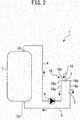
- Fig. 2 is a view illustrating the heat storage device 1 of the first embodiment.
- Fig. 2 is a view omitting the illustration of some devices included in the heat storage device 1 illustrated in Fig. 1 .
- the inverted U-shaped flow path 18 includes a first vertical portion 18a, a top portion 18b, a second vertical portion 18c, a first bend portion 18d, and a second bend portion 18e.
- the first vertical portion 18a and the second vertical portion 18c extend along the vertical direction.
- the top portion 18b extends along the horizontal direction.
- the first bend portion 18d is a bend portion between the upper end of the first vertical portion 18a and one end of the top portion 18b.
- the first vertical portion 18a, the top portion 18b, the first bend portion 18d, and the second bend portion 18e of the inverted U-shaped flow path 18 belongs to the first flow path 4.
- a part of the second vertical portion 18c belongs to the first flow path 4.
- the rest of the second vertical portion 18c belongs to the second flow path 5.
- the check valve 3 is provided in the second vertical portion 18c. Not limited to the configuration as above, all of the inverted U-shaped flow path 18 may belong to the first flow path 4.
- An operation of filling the closed circuit in the heat storage device 1 with heating medium is performed when the operation of the heat storage device 1 is started for the first time.
- the operation is hereinafter referred to as "filling operation".
- filling operation it is important to prevent air from remaining in the closed circuit.
- the pump 6 is operated in a state in which air remains in the closed circuit, there is a fear that the heating medium does not circulate smoothly or the pump 6 receives damage.
- the filler port 7 may include a valve (not shown) that automatically closes.
- the opening of the filler tube 19 may be closed instead of closing the filler port 7.
- the filler tube 19 may include a valve (not shown).
- FIG. 3 is a view illustrating a heat storage device 1A of the second embodiment.
- the illustration of some devices included in the heat storage device 1A is omitted as in Fig. 2 .
- the injected heating medium can also flow in the direction toward the pump 6 and an outlet 2d in the upper portion of the heat storage tank 2 from the filler port 7 through the first flow path 4.
- the air in the first flow path 4 and the pump 6 can also be efficiently removed.
- the filler port 7 may include a valve (not shown) that automatically closes.
- the second filler port 20 may be closed instead of closing the filler port 7.
- the second filler port 20 may include a valve (not shown) that automatically closes.
- the filler tube 21 may include a valve (not shown).
- FIG. 5 is a view illustrating a heat storage device 1C of the fourth embodiment.
- the illustration of some devices included in the heat storage device 1C is omitted as in Fig. 2 .
- the following effects can be further obtained in the filling operation in addition to the same effects as the third embodiment.
- the heating medium entering from the filler port 7 flows into the first vertical portion 18a through the first bend portion 18d.
- the heating medium is directly injected into the first bend portion 18d by providing the filler port 7 in the first bend portion 18d.
- the air in the first bend portion 18d can be removed more efficiently.
- the air in the bend portion 4a can be removed more efficiently by providing the filler port 7 vertically above the bend portion 4a.
- the heating medium easily enters the pump 6 by connecting the pump 6 to a place in the middle of the first vertical portion 18a, and hence the air in the pump 6 can be removed more efficiently.
- the same effects as the fourth embodiment can be obtained.
- the pump 6 may also be connected to a place in the middle of the first vertical portion 18a of the inverted U-shaped flow path 18 in the first embodiment and the third embodiment. Effects similar to that as above can be obtained also in that case.
- the heat storage device IE of the sixth embodiment includes the inverted U-shaped flow path 18.
- the inverted U-shaped flow path 18 includes the first vertical portion 18a, the top portion 18b, the second vertical portion 18c, the first bend portion 18d, and the second bend portion 18e.
- the first vertical portion 18a and the second vertical portion 18c extend along the vertical direction.
- the first bend portion 18d is a bend portion between the upper end of the first vertical portion 18a and one end of the top portion 18b.
- the second bend portion 18e is a bend portion between the upper end of the second vertical portion 18c and the other end of the top portion 18b.
- the filler port 7 is provided in the first bend portion 18d.
- the top portion 18b is inclined downward from the filler port 7 to the second bend portion 18e.
- the first bend portion 18d corresponds to the uppermost portion of the inverted U-shaped flow path 18.
- the bend portion 4a is provided between the lower end of the first vertical portion 18a and the discharge outlet of the pump 6.
- the filler port 7 is provided vertically above the bend portion 4a.
Landscapes
- Engineering & Computer Science (AREA)
- Physics & Mathematics (AREA)
- Thermal Sciences (AREA)
- Mechanical Engineering (AREA)
- General Engineering & Computer Science (AREA)
- Chemical & Material Sciences (AREA)
- Combustion & Propulsion (AREA)
- Heat-Pump Type And Storage Water Heaters (AREA)
- Details Of Fluid Heaters (AREA)
Abstract
Description
- The present invention relates to a heat storage device.
- A hot water tank structure disclosed in PTL 1 described below has the following configuration. A circulation pipeline (R) is formed from an inlet pipeline (10) extending from a hot water supplying outlet (11) to an inlet (4a) of a hot water tank (4), an outlet pipeline (17) extending from an outlet (4b) of the hot water tank (4) to a hot water outlet (18), and a bypass passage (19) connecting the hot water supplying outlet (11) to the hot water outlet (18). A check valve (15) is provided in the inlet pipeline (10) in the forward direction.
- [PTL 1]
Japanese Patent Application Publication No.2001-124417 - In the feature of PTL 1, hot water from the outside flows into the hot water supplying outlet (11), and hot water in the hot water tank (4) is supplied to the outside from the hot water outlet (18). That is, the circulation pipeline (R) described in PTL 1 is an open system. A pump is not installed in the circulation pipeline (R).
- There is a heat storage device that circulates a liquid heating medium stored in a heat storage tank in a closed circuit with use of a pump. In such a heat storage device having a closed system, an operation of injecting the heating medium into the closed circuit from the outside and filling the closed circuit with the heating medium is needed only at the beginning of the operation of the heat storage device. When the pump operates while there is still air in the closed circuit, there is a fear that the heating medium does not circulate smoothly or the pump receives damage.
- The present invention has been made in order to solve the problems as described above, and an object thereof is to provide a heat storage device capable of efficiently removing air in a closed circuit when an operation of filling the closed circuit with a heating medium is performed.
- A heat storage device according to the present invention includes: a heat storage tank having an inlet and an outlet, and configured to store a liquid heating medium; a check valve having an inlet and an outlet; a first flow path configured to connect the outlet of the heat storage tank to the inlet of the check valve; a second flow path configured to connect the outlet of the check valve to the inlet of the heat storage tank; a pump provided in the first flow path and configured to transfer the heating medium; and a filler port provided in the first flow path. When a closed circuit including the heat storage tank, the check valve, the first flow path, the second flow path, and the pump is filled with the heating medium, the heating medium supplied from an external supply source is injected into the first flow path through the filler port.
- According to the heat storage device of the present invention, the air in the closed circuit can be efficiently removed when the operation of filling the closed circuit with the heating medium is performed.
-
-
Fig. 1 is a view illustrating a heat storage device of a first embodiment. -
Fig. 2 is a view illustrating the heat storage device of the first embodiment. -
Fig. 3 is a view illustrating a heat storage device of a second embodiment. -
Fig. 4 is a view illustrating a heat storage device of a third embodiment. -
Fig. 5 is a view illustrating a heat storage device of a fourth embodiment. -
Fig. 6 is a view illustrating a heat storage device of a fifth embodiment. -
Fig. 7 is a view illustrating a heat storage device of a sixth embodiment. - Embodiments are described below with reference to the drawings. Common elements in the drawings are denoted by the same symbols, and overlapping descriptions are simplified or omitted. This disclosure may include all the combinations of the combinable configurations out of the configurations to be described in the embodiments below.
-
Fig. 1 is a view illustrating a heat storage device of a first embodiment. As illustrated inFig. 1 , a heat storage device 1 of the first embodiment includes ahousing 10. The heat storage device 1 further includes aheat storage tank 2, acheck valve 3, afirst flow path 4, asecond flow path 5, apump 6, afiller port 7, aheat exchanger 8, and apump 9 accommodated in thehousing 10. - The heat storage device 1 further includes a
heat pump device 11. In the example illustrated inFig. 1 , theheat pump device 11 is installed outside thehousing 10. Theheat pump device 11 may be installed in thehousing 10. Theheat pump device 11 is an example of heating means for heating a liquid heating medium. The heating medium may be water. The heating medium may be brine other than water such as calcium chloride solution, ethylene glycol solution, and alcohol. - Although not shown, the
heat pump device 11 includes a refrigerant circuit. The refrigerant circuit may include a compressor that compresses a refrigerant, a heat exchanger that exchanges heat between the high-pressure and high-temperature refrigerant compressed by the compressor and the heating medium, a decompression device that decompresses the refrigerant, and an evaporator that evaporates the refrigerant. - The heating means for heating the heating medium is not limited to the
heat pump device 11. The heating means may be one of an electric heater, a solar thermal collector, and a fuel burning heater. A plurality of heating means may be included. - The
heat storage tank 2 stores the heating medium. When the heat storage device 1 is in operation, theheat storage tank 2 is maintained to be in a state filled with the heating medium. Thermal stratification in which the temperature of the upper side is high and the temperature of the lower side is low can be formed in theheat storage tank 2 due to the density difference in the heating medium depending on temperature difference. - The
heat storage tank 2 includes aninlet 2a, anoutlet 2b, aninlet 2c, and anoutlet 2d. Theinlet 2a and theoutlet 2d are provided in the upper portion of theheat storage tank 2. In the example illustrated inFig. 1 , theinlet 2a and theoutlet 2d are provided in the uppermost portion of theheat storage tank 2. Theoutlet 2b and theinlet 2c are provided in the lower portion of theheat storage tank 2. In the example illustrated inFig. 1 , theoutlet 2b and theinlet 2c are provided in the lowermost portion of theheat storage tank 2. Apipe 12 connects theoutlet 2b in the lower portion of theheat storage tank 2 to an inlet of theheat pump device 11. Thepump 9 that transfers the heating medium is installed in the middle of thepipe 12. Apipe 13 connects an outlet of theheat pump device 11 to theinlet 2a in the upper portion of theheat storage tank 2. - The heat storage device 1 can perform heat accumulating operation. The heat accumulating operation is an operation of accumulating a high-temperature heating medium in the
heat storage tank 2. The heat accumulating operation is performed as follows. Thepump 9 and theheat pump device 11 are operated. A low-temperature heating medium in theheat storage tank 2 exits theoutlet 2b and is sent to theheat pump device 11 through thepipe 12. The heating medium of which temperature has increased by being heated in theheat pump device 11 returns to theheat storage tank 2 through thepipe 13. The high-temperature heating medium flows into theheat storage tank 2 from theinlet 2a. The high-temperature heating medium gradually accumulates in theheat storage tank 2 from the top to the bottom thereof. - The circuit in which the heating medium circulates in the heat accumulating operation is a closed circuit. That is, the circuit including the
heat storage tank 2, thepump 9, theheat pump device 11, thepipe 12, and thepipe 13 is a closed circuit. The expression "closed circuit" herein means a closed system into or out of which a substance, that is, a heating medium does not enter or exit the outside of the system. - The
first flow path 4 connects theoutlet 2d in the upper portion of theheat storage tank 2 to an inlet of thecheck valve 3. Thesecond flow path 5 connects an outlet of thecheck valve 3 to theinlet 2c in the lower portion of theheat storage tank 2. Thepump 6 transfers the heating medium. Thepump 6 is provided in thefirst flow path 4. Thefiller port 7 is provided in thefirst flow path 4. - The
heat exchanger 8 exchanges heat between the heating medium supplied from theheat storage tank 2 and water supplied from the outside. Aflow path 8a of the heating medium included in theheat exchanger 8 forms a part of thefirst flow path 4. The flow path of the water included in theheat exchanger 8 includes afirst end 8b connected awater supply pipe 14 and asecond end 8c connected to a hotwater supply pipe 15. Thepump 6 is downstream of theheat exchanger 8 in thefirst flow path 4. Thefiller port 7 is downstream of thepump 6. - The heat storage device 1 can perform hot water supply operation. The hot water supply operation is performed as following. The
pump 6 is operated. The heating medium flows through thefirst flow path 4 and thesecond flow path 5. Water flows from an external water source into theheat exchanger 8 through thewater supply pipe 14. The high-temperature heating medium exiting theoutlet 2d in the upper portion of theheat storage tank 2 flows into theheat exchanger 8. The heating medium heats the water in theheat exchanger 8. The hot water of which temperature has increased by being heated in theheat exchanger 8 is supplied to an external terminal through the hotwater supply pipe 15. The heating medium of which temperature has decreased by being cooled in theheat exchanger 8 returns to theheat storage tank 2 via thepump 6, thecheck valve 3, and thesecond flow path 5. The heating medium flows into theheat storage tank 2 from theinlet 2c. - The circuit in which the heating medium circulates in the hot water supply operation is a closed circuit. That is, the circuit including the
heat storage tank 2, thecheck valve 3, thefirst flow path 4, thesecond flow path 5, and thepump 6 is a closed circuit. The expression "closed circuit" herein means a closed system into or out of which a substance, that is, a heating medium does not enter or exit the outside of the system. - An
air vent valve 16 is connected to the uppermost portion of thepipe 13. Anair vent valve 17 is connected to the uppermost portion of thefirst flow path 4. Theair vent valves air vent valves air vent valves heat storage tank 2. - There may be a case where the
pump 6 is removed from thefirst flow path 4 in order to maintain thepump 6. In a case without thecheck valve 3, when thepump 6 is removed, the heating medium in theheat storage tank 2 flows backward in thesecond flow path 5 due to hydraulic head pressure and starts to leak from the place in which thepump 6 used to be connected. Meanwhile, in this embodiment, the following effect can be obtained by including thecheck valve 3. The heating medium in theheat storage tank 2 can be automatically prevented from flowing backward in thesecond flow path 5 when thepump 6 is removed. - The heat storage device 1 of this embodiment includes an inverted
U-shaped flow path 18. The invertedU-shaped flow path 18 is provided for the purpose of efficiently accommodating devices in the small space in thehousing 10 in order to miniaturize the heat storage device 1. The invertedU-shaped flow path 18 is provided in order to step over other devices (not shown). Thefiller port 7 is provided in the upper portion of the invertedU-shaped flow path 18. -
Fig. 2 is a view illustrating the heat storage device 1 of the first embodiment.Fig. 2 is a view omitting the illustration of some devices included in the heat storage device 1 illustrated inFig. 1 . As illustrated inFig. 2 , the invertedU-shaped flow path 18 includes a firstvertical portion 18a, atop portion 18b, a secondvertical portion 18c, afirst bend portion 18d, and asecond bend portion 18e. The firstvertical portion 18a and the secondvertical portion 18c extend along the vertical direction. Thetop portion 18b extends along the horizontal direction. Thefirst bend portion 18d is a bend portion between the upper end of the firstvertical portion 18a and one end of thetop portion 18b. Thesecond bend portion 18e is a bend portion between the upper end of the secondvertical portion 18c and the other end of thetop portion 18b. Thefiller port 7 is provided in thetop portion 18b. Thetop portion 18b corresponds to the uppermost portion of the invertedU-shaped flow path 18. - In this embodiment, the first
vertical portion 18a, thetop portion 18b, thefirst bend portion 18d, and thesecond bend portion 18e of the invertedU-shaped flow path 18 belongs to thefirst flow path 4. A part of the secondvertical portion 18c belongs to thefirst flow path 4. The rest of the secondvertical portion 18c belongs to thesecond flow path 5. Thecheck valve 3 is provided in the secondvertical portion 18c. Not limited to the configuration as above, all of the invertedU-shaped flow path 18 may belong to thefirst flow path 4. - An operation of filling the closed circuit in the heat storage device 1 with heating medium is performed when the operation of the heat storage device 1 is started for the first time. The operation is hereinafter referred to as "filling operation". In the filling operation, it is important to prevent air from remaining in the closed circuit. When the
pump 6 is operated in a state in which air remains in the closed circuit, there is a fear that the heating medium does not circulate smoothly or thepump 6 receives damage. - The filling operation is described below. The direction in which the heating medium flows in the filling operation is indicated by the arrows in
Fig. 2 . The filling operation is performed as the following. An external supply source is connected to afiller tube 19 communicating with thefiller port 7. A heating medium supplied from the supply source is injected into thefirst flow path 4 through thefiller tube 19 and thefiller port 7. The injected heating medium can flow into theheat storage tank 2 from theinlet 2c in the lower portion of theheat storage tank 2 through thecheck valve 3 and thesecond flow path 5. As a result, the heating medium is accumulated in theheat storage tank 2. The injected heating medium can also flow in the direction toward thepump 6 and theoutlet 2d in the upper portion of theheat storage tank 2 from thefiller port 7 through thefirst flow path 4. As a result, thefirst flow path 4 and thepump 6 can also be filled with the heating medium without causing air to remain therein. The air in the closed circuit is discharged to the outside of the system through theair vent valves pipe 12, thepump 9, theheat pump device 11, and thepipe 13 are also filled with the heating medium because the heating medium in theheat storage tank 2 flows into thepipe 12 from theoutlet 2b. - If the
filler port 7 is provided in thesecond flow path 5, the following result is obtained. The injected heating medium cannot flow into thefirst flow path 4 due to thecheck valve 3. As a result, air tends to remain in thefirst flow path 4 and thepump 6. That is, the air in the closed circuit cannot be efficiently removed. Meanwhile, in this embodiment, thefiller port 7 is provided in thefirst flow path 4, and hence the air in the closed circuit can be efficiently removed. - In general, when there is an inverted U-shaped flow path, the air in the upper portion of the inverted U-shaped flow path is not easily removed. In general, an air vent valve for removing air is connected to the upper portion of the inverted U-shaped flow path in many cases. Meanwhile, in this embodiment, the following effect can be obtained by directly injecting the heating medium into the upper portion of the inverted
U-shaped flow path 18 from thefiller port 7. The air in the invertedU-shaped flow path 18 can be efficiently removed even without connecting an air vent valve to the upper portion of the invertedU-shaped flow path 18. In particular, in this embodiment, the air in the invertedU-shaped flow path 18 can be removed more efficiently by providing thefiller port 7 in the uppermost portion of the invertedU-shaped flow path 18. - After the filling operation has completed, sealing is performed so that the heating medium does not leak from the
filler port 7. Thefiller port 7 may include a valve (not shown) that automatically closes. The opening of thefiller tube 19 may be closed instead of closing thefiller port 7. Thefiller tube 19 may include a valve (not shown). - Next, a second embodiment is described with reference to
Fig. 3 . The differences from the first embodiment described above are mainly described, and the description of the same parts or corresponding parts are simplified or omitted.Fig. 3 is a view illustrating aheat storage device 1A of the second embodiment. InFig. 3 , the illustration of some devices included in theheat storage device 1A is omitted as inFig. 2 . - The
heat storage device 1A of the second embodiment illustrated inFig. 3 does not include the invertedU-shaped flow path 18. A filling operation of the second embodiment is described below. The direction in which the heating medium flows in the filling operation is indicated by the arrows inFig. 3 . The filling operation is performed as follows. The external supply source is connected to thefiller tube 19 communicating with thefiller port 7. The heating medium supplied from the supply source is injected into thefirst flow path 4 through thefiller tube 19 and thefiller port 7. The injected heating medium can flow into theheat storage tank 2 from aninlet 2c in the lower portion of theheat storage tank 2 through thecheck valve 3 and thesecond flow path 5. The injected heating medium can also flow in the direction toward thepump 6 and anoutlet 2d in the upper portion of theheat storage tank 2 from thefiller port 7 through thefirst flow path 4. As a result, the air in thefirst flow path 4 and thepump 6 can also be efficiently removed. - If the
filler port 7 is provided in thesecond flow path 5, the following result is obtained. The injected heating medium cannot flow into thefirst flow path 4 due to thecheck valve 3. As a result, air tends to remain in thefirst flow path 4 and thepump 6. That is, the air in the closed circuit cannot be efficiently removed. Meanwhile, in this embodiment, thefiller port 7 is provided in thefirst flow path 4, and hence the air in the closed circuit can be efficiently removed. - Next, a third embodiment is described with reference to
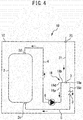
Fig. 4 . The differences from the first embodiment described above are mainly described, and the description of the same parts or corresponding parts are simplified or omitted.Fig. 4 is a view illustrating aheat storage device 1B of the third embodiment. InFig. 4 , the illustration of some devices included in theheat storage device 1B is omitted as inFig. 2 . - The
heat storage device 1B of the third embodiment illustrated inFig. 4 includes asecond filler port 20 provided in thehousing 10. Theheat storage device 1B includes afiller tube 21 instead of thefiller tube 19 of the first embodiment. Thefiller tube 21 connects thefiller port 7 to thesecond filler port 20. Thesecond filler port 20 is provided in the upper portion of thehousing 10. - A filling operation of the third embodiment is described below. The direction in which the heating medium flows in the filling operation is indicated by the arrows in
Fig. 4 . The filling operation is performed as follows. The external supply source is connected to thesecond filler port 20. The heating medium supplied from the supply source is injected into thefirst flow path 4 through thesecond filler port 20, thefiller tube 21, and thefiller port 7. The flow of the heating medium thereafter is the same as that in the first embodiment, and hence description thereof is omitted. - In this embodiment, the following effect can be further obtained in addition to the same effects as the first embodiment. The supply source of the heating medium can be connected to the
second filler port 20 from the outside of thehousing 10 in the filling operation. Therefore, there is no need to remove a part of thehousing 10 or open thehousing 10 in the filling operation, and it is easy to work. There is a low possibility of air remaining in the filling operation because thesecond filler port 20 is provided in the upper portion of thehousing 10, and hence the air in the closed circuit can be efficiently removed. - After the filling operation has completed, sealing is performed so that the heating medium does not leak from the
filler port 7. Thefiller port 7 may include a valve (not shown) that automatically closes. Thesecond filler port 20 may be closed instead of closing thefiller port 7. Thesecond filler port 20 may include a valve (not shown) that automatically closes. Thefiller tube 21 may include a valve (not shown). - Next, a fourth embodiment is described with reference to
Fig. 5 . The differences from the first embodiment described above are mainly described, and the description of the same parts or corresponding parts are simplified or omitted.Fig. 5 is a view illustrating a heat storage device 1C of the fourth embodiment. InFig. 5 , the illustration of some devices included in the heat storage device 1C is omitted as inFig. 2 . - The heat storage device 1C of the fourth embodiment illustrated in
Fig. 5 includes the invertedU-shaped flow path 18. The invertedU-shaped flow path 18 includes the firstvertical portion 18a, thetop portion 18b, the secondvertical portion 18c, thefirst bend portion 18d, and thesecond bend portion 18e. The firstvertical portion 18a and the secondvertical portion 18c extend along the vertical direction. Thetop portion 18b extends along the horizontal direction. Thefirst bend portion 18d is a bend portion between the upper end of the firstvertical portion 18a and one end of thetop portion 18b. Thesecond bend portion 18e is a bend portion between the upper end of the secondvertical portion 18c and the other end of thetop portion 18b. Thefiller port 7 is provided in thefirst bend portion 18d. Abend portion 4a is provided between the lower end of the firstvertical portion 18a and a discharge outlet of thepump 6. Thefiller port 7 is provided vertically above thebend portion 4a. - In the fourth embodiment, the following effects can be further obtained in the filling operation in addition to the same effects as the third embodiment. When a bend portion in the flow path is filled with the heating medium, there is a fear that air is collected in the bend portion. In the third embodiment, the heating medium entering from the
filler port 7 flows into the firstvertical portion 18a through thefirst bend portion 18d. Meanwhile, in the fourth embodiment, the heating medium is directly injected into thefirst bend portion 18d by providing thefiller port 7 in thefirst bend portion 18d. As a result, the air in thefirst bend portion 18d can be removed more efficiently. Further, in this embodiment, the air in thebend portion 4a can be removed more efficiently by providing thefiller port 7 vertically above thebend portion 4a. - The position of the
filler port 7 may be in thesecond bend portion 18e instead of in thefirst bend portion 18d. Effects similar to those as above can be obtained also in that case. - Next, a fifth embodiment is described with reference to
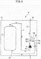
Fig. 6 . The differences from the fourth embodiment described above are mainly described, and the description of the same parts or corresponding parts are simplified or omitted.Fig. 6 is a view illustrating a heat storage device ID of the fifth embodiment. InFig. 6 , the illustration of some devices included in the heat storage device ID is omitted as inFig. 2 . - As illustrated in
Fig. 6 , in the heat storage device ID of the fifth embodiment, the position of thepump 6 is different from that of the fourth embodiment. Thepump 6 is connected to a place in the middle of the firstvertical portion 18a of the invertedU-shaped flow path 18. - In general, it may take time to remove the air in the
pump 6 in the filling operation. In the fifth embodiment, the heating medium easily enters thepump 6 by connecting thepump 6 to a place in the middle of the firstvertical portion 18a, and hence the air in thepump 6 can be removed more efficiently. In addition, in the fifth embodiment, the same effects as the fourth embodiment can be obtained. - The
pump 6 may also be connected to a place in the middle of the firstvertical portion 18a of the invertedU-shaped flow path 18 in the first embodiment and the third embodiment. Effects similar to that as above can be obtained also in that case. - Next, a sixth embodiment is described with reference to
Fig. 7 . The differences from the fifth embodiment described above are mainly described, and the description of the same parts or corresponding parts are simplified or omitted.Fig. 7 is a view illustrating a heat storage device IE of the sixth embodiment. InFig. 7 , the illustration of some devices included in the heat storage device IE is omitted as inFig. 2 . - As illustrated in
Fig. 7 , the heat storage device IE of the sixth embodiment includes the invertedU-shaped flow path 18. The invertedU-shaped flow path 18 includes the firstvertical portion 18a, thetop portion 18b, the secondvertical portion 18c, thefirst bend portion 18d, and thesecond bend portion 18e. The firstvertical portion 18a and the secondvertical portion 18c extend along the vertical direction. Thefirst bend portion 18d is a bend portion between the upper end of the firstvertical portion 18a and one end of thetop portion 18b. Thesecond bend portion 18e is a bend portion between the upper end of the secondvertical portion 18c and the other end of thetop portion 18b. Thefiller port 7 is provided in thefirst bend portion 18d. Thetop portion 18b is inclined downward from thefiller port 7 to thesecond bend portion 18e. Thefirst bend portion 18d corresponds to the uppermost portion of the invertedU-shaped flow path 18. Thebend portion 4a is provided between the lower end of the firstvertical portion 18a and the discharge outlet of thepump 6. Thefiller port 7 is provided vertically above thebend portion 4a. - In the sixth embodiment, the following effect can be further obtained in the filling operation in addition to the same effects as the fifth embodiment. The air collected in the
second bend portion 18e is guided to thefiller port 7 due to buoyancy. As a result, the air in thesecond bend portion 18e can be removed more efficiently. -
- 1, 1A, 1B, 1C, 1D, 1E Heat storage device
- 2 Heat storage tank
- 2a Inlet
- 2b Outlet
- 2c Inlet
- 2d Outlet
- 3 Check valve
- 4 First flow path
- 4a Bend portion
- 5 Second flow path
- 6 Pump
- 7 Filler port
- 8 Heat exchanger
- 9 Pump
- 10 Housing
- 11 Heat pump device
- 12, 13 Pipe
- 14 Water supply pipe
- 15 Hot water supply pipe
- 16, 17 Air vent valve
- 18 Inverted U-shaped flow path
- 18a First vertical portion
- 18b Top portion
- 18c Second vertical portion
- 18d First bend portion
- 18e Second bend portion
- 19 Filler tube
- 20 Second filler port
- 21 Filler tube
Claims (7)
- A heat storage device, comprising:a heat storage tank having an inlet and an outlet, and configured to store a liquid heating medium;a check valve having an inlet and an outlet;a first flow path configured to connect the outlet of the heat storage tank to the inlet of the check valve;a second flow path configured to connect the outlet of the check valve to the inlet of the heat storage tank;a pump provided in the first flow path and configured to transfer the heating medium; anda filler port provided in the first flow path, whereinwhen a closed circuit including the heat storage tank, the check valve, the first flow path, the second flow path, and the pump is filled with the heating medium, the heating medium supplied from an external supply source is injected into the first flow path through the filler port.
- The heat storage device according to claim 1, further comprising an inverted U-shaped flow path, wherein
the filler port is provided in an upper portion of the inverted U-shaped flow path. - The heat storage device according to claim 2, wherein:the inverted U-shaped flow path includes a vertical portion, a top portion, and a bend portion between the vertical portion and the top portion; andthe filler port is provided in the bend portion.
- The heat storage device according to claim 2 or 3, wherein:the inverted U-shaped flow path includes a vertical portion; andthe pump is provided in the vertical portion.
- The heat storage device according to any one of claims 2 to 4, wherein the filler port is provided in an uppermost portion of the inverted U-shaped flow path.
- The heat storage device according to any one of claims 1 to 5, further comprising:a housing configured to accommodate the heat storage tank, the check valve, the first flow path, the second flow path, and the pump;a second filler port provided in the housing; anda filler tube configured to connect the filler port to the second filler port.
- The heat storage device according to any one of claims 1 to 6, further comprising air removing means configured to remove air in the closed circuit.
Applications Claiming Priority (1)
| Application Number | Priority Date | Filing Date | Title |
|---|---|---|---|
| PCT/JP2016/061693 WO2017179098A1 (en) | 2016-04-11 | 2016-04-11 | Heat storage device |
Publications (3)
| Publication Number | Publication Date |
|---|---|
| EP3444537A1 true EP3444537A1 (en) | 2019-02-20 |
| EP3444537A4 EP3444537A4 (en) | 2019-03-27 |
| EP3444537B1 EP3444537B1 (en) | 2021-03-03 |
Family
ID=60042412
Family Applications (1)
| Application Number | Title | Priority Date | Filing Date |
|---|---|---|---|
| EP16898558.8A Not-in-force EP3444537B1 (en) | 2016-04-11 | 2016-04-11 | Heat storage device |
Country Status (3)
| Country | Link |
|---|---|
| EP (1) | EP3444537B1 (en) |
| JP (1) | JP6528903B2 (en) |
| WO (1) | WO2017179098A1 (en) |
Families Citing this family (1)
| Publication number | Priority date | Publication date | Assignee | Title |
|---|---|---|---|---|
| CN113405078B (en) * | 2021-07-09 | 2024-12-10 | 上海电气集团股份有限公司 | A heat storage steam supply system |
Family Cites Families (10)
| Publication number | Priority date | Publication date | Assignee | Title |
|---|---|---|---|---|
| JPH0579313U (en) * | 1992-03-16 | 1993-10-29 | ダイキン工業株式会社 | Heat medium circulation heating system |
| JP2001124417A (en) * | 1999-10-22 | 2001-05-11 | Inax Corp | Hot-water tank structure |
| CA2434379C (en) * | 2003-07-04 | 2005-11-15 | Robert Moncrieff | Heat exchanger device |
| DE50313603D1 (en) * | 2003-11-03 | 2011-05-19 | Grundfos As | Assembly unit for a compact heating system |
| JP5166709B2 (en) * | 2006-07-12 | 2013-03-21 | 東芝キヤリア株式会社 | Water heater |
| EP1884720B1 (en) * | 2006-07-28 | 2016-01-13 | Grundfos Management A/S | Assembly for a compact heating installation |
| JP2008128508A (en) * | 2006-11-17 | 2008-06-05 | Toshiba Electric Appliance Co Ltd | Hot water supply system |
| JP2010255964A (en) * | 2009-04-27 | 2010-11-11 | Sanyo Electric Co Ltd | Cleaning method of heat pump water heater, and heat pump water heater |
| JP5492059B2 (en) * | 2010-11-19 | 2014-05-14 | 日立アプライアンス株式会社 | Water heater |
| JP2015175540A (en) * | 2014-03-14 | 2015-10-05 | パナソニックIpマネジメント株式会社 | Heat exchange device for hot water supply and hot water supply device having the same |
-
2016
- 2016-04-11 EP EP16898558.8A patent/EP3444537B1/en not_active Not-in-force
- 2016-04-11 WO PCT/JP2016/061693 patent/WO2017179098A1/en not_active Ceased
- 2016-04-11 JP JP2018511555A patent/JP6528903B2/en active Active
Also Published As
| Publication number | Publication date |
|---|---|
| JP6528903B2 (en) | 2019-06-12 |
| EP3444537B1 (en) | 2021-03-03 |
| JPWO2017179098A1 (en) | 2018-07-26 |
| WO2017179098A1 (en) | 2017-10-19 |
| EP3444537A4 (en) | 2019-03-27 |
Similar Documents
| Publication | Publication Date | Title |
|---|---|---|
| ES2574432T3 (en) | Refrigerant circuit | |
| CN206235051U (en) | A kind of interval cooling liquid cool equipment of double water tank | |
| CN116923139A (en) | Cooling equipment for charging station | |
| EP3444537A1 (en) | Heat storage device | |
| KR101606531B1 (en) | Hybrid Heat Pump Boiler System | |
| JP6209941B2 (en) | Boiler system | |
| CN100541065C (en) | Heat-transfer-medium heating and cooling apparatus | |
| US11035628B2 (en) | System for fast draining of an airfan heat exchanger and methods of using the same | |
| JP5399327B2 (en) | Hot water storage tank unit | |
| JP6209940B2 (en) | Boiler system | |
| JP5556476B2 (en) | Hot water storage water heater | |
| EP4344369A1 (en) | Pump-driven two-phase liquid cooling system, and liquid supplementation control method for pump-driven two-phase liquid cooling system | |
| JP2006286516A (en) | Fuel cell system | |
| KR100853965B1 (en) | Solar heating system using heating water pipe | |
| JPWO2016189663A1 (en) | Heat pump hot water supply system | |
| JP4969422B2 (en) | Hot water storage type electric water heater | |
| KR20150084424A (en) | System for supplying hot water using solar enegy | |
| CN217509291U (en) | Degasser of cooling circulation system | |
| RU2761108C1 (en) | Passive heat discharge system of the reactor plant | |
| JP2015190742A (en) | Boiler system | |
| US20250354719A1 (en) | Water heating system | |
| CN203744541U (en) | Hot water supply device | |
| EP3290823B1 (en) | Solar heat collection system | |
| CN117183784A (en) | A cooling system for new energy vehicle charging stations | |
| KR101784107B1 (en) | Solar heating apparatus |
Legal Events
| Date | Code | Title | Description |
|---|---|---|---|
| STAA | Information on the status of an ep patent application or granted ep patent |
Free format text: STATUS: THE INTERNATIONAL PUBLICATION HAS BEEN MADE |
|
| PUAI | Public reference made under article 153(3) epc to a published international application that has entered the european phase |
Free format text: ORIGINAL CODE: 0009012 |
|
| STAA | Information on the status of an ep patent application or granted ep patent |
Free format text: STATUS: REQUEST FOR EXAMINATION WAS MADE |
|
| 17P | Request for examination filed |
Effective date: 20180914 |
|
| AK | Designated contracting states |
Kind code of ref document: A1 Designated state(s): AL AT BE BG CH CY CZ DE DK EE ES FI FR GB GR HR HU IE IS IT LI LT LU LV MC MK MT NL NO PL PT RO RS SE SI SK SM TR |
|
| AX | Request for extension of the european patent |
Extension state: BA ME |
|
| A4 | Supplementary search report drawn up and despatched |
Effective date: 20190226 |
|
| RIC1 | Information provided on ipc code assigned before grant |
Ipc: F24D 3/10 20060101ALI20190220BHEP Ipc: F24H 4/04 20060101ALI20190220BHEP Ipc: F24H 9/00 20060101AFI20190220BHEP Ipc: F24H 1/18 20060101ALI20190220BHEP Ipc: F24D 17/02 20060101ALI20190220BHEP |
|
| DAV | Request for validation of the european patent (deleted) | ||
| DAX | Request for extension of the european patent (deleted) | ||
| STAA | Information on the status of an ep patent application or granted ep patent |
Free format text: STATUS: EXAMINATION IS IN PROGRESS |
|
| 17Q | First examination report despatched |
Effective date: 20191203 |
|
| GRAP | Despatch of communication of intention to grant a patent |
Free format text: ORIGINAL CODE: EPIDOSNIGR1 |
|
| STAA | Information on the status of an ep patent application or granted ep patent |
Free format text: STATUS: GRANT OF PATENT IS INTENDED |
|
| RIC1 | Information provided on ipc code assigned before grant |
Ipc: F24D 17/02 20060101ALI20200511BHEP Ipc: F28D 20/00 20060101ALI20200511BHEP Ipc: F24D 3/10 20060101ALI20200511BHEP Ipc: F24H 9/00 20060101AFI20200511BHEP Ipc: F24H 1/18 20060101ALI20200511BHEP Ipc: F24H 4/04 20060101ALI20200511BHEP |
|
| INTG | Intention to grant announced |
Effective date: 20200603 |
|
| GRAJ | Information related to disapproval of communication of intention to grant by the applicant or resumption of examination proceedings by the epo deleted |
Free format text: ORIGINAL CODE: EPIDOSDIGR1 |
|
| STAA | Information on the status of an ep patent application or granted ep patent |
Free format text: STATUS: EXAMINATION IS IN PROGRESS |
|
| GRAP | Despatch of communication of intention to grant a patent |
Free format text: ORIGINAL CODE: EPIDOSNIGR1 |
|
| STAA | Information on the status of an ep patent application or granted ep patent |
Free format text: STATUS: GRANT OF PATENT IS INTENDED |
|
| GRAJ | Information related to disapproval of communication of intention to grant by the applicant or resumption of examination proceedings by the epo deleted |
Free format text: ORIGINAL CODE: EPIDOSDIGR1 |
|
| STAA | Information on the status of an ep patent application or granted ep patent |
Free format text: STATUS: EXAMINATION IS IN PROGRESS |
|
| INTG | Intention to grant announced |
Effective date: 20201016 |
|
| GRAP | Despatch of communication of intention to grant a patent |
Free format text: ORIGINAL CODE: EPIDOSNIGR1 |
|
| STAA | Information on the status of an ep patent application or granted ep patent |
Free format text: STATUS: GRANT OF PATENT IS INTENDED |
|
| INTC | Intention to grant announced (deleted) | ||
| INTG | Intention to grant announced |
Effective date: 20201119 |
|
| GRAS | Grant fee paid |
Free format text: ORIGINAL CODE: EPIDOSNIGR3 |
|
| GRAA | (expected) grant |
Free format text: ORIGINAL CODE: 0009210 |
|
| STAA | Information on the status of an ep patent application or granted ep patent |
Free format text: STATUS: THE PATENT HAS BEEN GRANTED |
|
| AK | Designated contracting states |
Kind code of ref document: B1 Designated state(s): AL AT BE BG CH CY CZ DE DK EE ES FI FR GB GR HR HU IE IS IT LI LT LU LV MC MK MT NL NO PL PT RO RS SE SI SK SM TR |
|
| REG | Reference to a national code |
Ref country code: GB Ref legal event code: FG4D |
|
| REG | Reference to a national code |
Ref country code: AT Ref legal event code: REF Ref document number: 1367639 Country of ref document: AT Kind code of ref document: T Effective date: 20210315 Ref country code: CH Ref legal event code: EP |
|
| REG | Reference to a national code |
Ref country code: DE Ref legal event code: R096 Ref document number: 602016053824 Country of ref document: DE |
|
| REG | Reference to a national code |
Ref country code: SE Ref legal event code: TRGR |
|
| REG | Reference to a national code |
Ref country code: IE Ref legal event code: FG4D |
|
| REG | Reference to a national code |
Ref country code: LT Ref legal event code: MG9D |
|
| PG25 | Lapsed in a contracting state [announced via postgrant information from national office to epo] |
Ref country code: LT Free format text: LAPSE BECAUSE OF FAILURE TO SUBMIT A TRANSLATION OF THE DESCRIPTION OR TO PAY THE FEE WITHIN THE PRESCRIBED TIME-LIMIT Effective date: 20210303 Ref country code: BG Free format text: LAPSE BECAUSE OF FAILURE TO SUBMIT A TRANSLATION OF THE DESCRIPTION OR TO PAY THE FEE WITHIN THE PRESCRIBED TIME-LIMIT Effective date: 20210603 Ref country code: NO Free format text: LAPSE BECAUSE OF FAILURE TO SUBMIT A TRANSLATION OF THE DESCRIPTION OR TO PAY THE FEE WITHIN THE PRESCRIBED TIME-LIMIT Effective date: 20210603 Ref country code: GR Free format text: LAPSE BECAUSE OF FAILURE TO SUBMIT A TRANSLATION OF THE DESCRIPTION OR TO PAY THE FEE WITHIN THE PRESCRIBED TIME-LIMIT Effective date: 20210604 Ref country code: FI Free format text: LAPSE BECAUSE OF FAILURE TO SUBMIT A TRANSLATION OF THE DESCRIPTION OR TO PAY THE FEE WITHIN THE PRESCRIBED TIME-LIMIT Effective date: 20210303 Ref country code: HR Free format text: LAPSE BECAUSE OF FAILURE TO SUBMIT A TRANSLATION OF THE DESCRIPTION OR TO PAY THE FEE WITHIN THE PRESCRIBED TIME-LIMIT Effective date: 20210303 |
|
| REG | Reference to a national code |
Ref country code: NL Ref legal event code: MP Effective date: 20210303 |
|
| REG | Reference to a national code |
Ref country code: AT Ref legal event code: MK05 Ref document number: 1367639 Country of ref document: AT Kind code of ref document: T Effective date: 20210303 |
|
| PG25 | Lapsed in a contracting state [announced via postgrant information from national office to epo] |
Ref country code: LV Free format text: LAPSE BECAUSE OF FAILURE TO SUBMIT A TRANSLATION OF THE DESCRIPTION OR TO PAY THE FEE WITHIN THE PRESCRIBED TIME-LIMIT Effective date: 20210303 Ref country code: PL Free format text: LAPSE BECAUSE OF FAILURE TO SUBMIT A TRANSLATION OF THE DESCRIPTION OR TO PAY THE FEE WITHIN THE PRESCRIBED TIME-LIMIT Effective date: 20210303 Ref country code: RS Free format text: LAPSE BECAUSE OF FAILURE TO SUBMIT A TRANSLATION OF THE DESCRIPTION OR TO PAY THE FEE WITHIN THE PRESCRIBED TIME-LIMIT Effective date: 20210303 |
|
| PG25 | Lapsed in a contracting state [announced via postgrant information from national office to epo] |
Ref country code: NL Free format text: LAPSE BECAUSE OF FAILURE TO SUBMIT A TRANSLATION OF THE DESCRIPTION OR TO PAY THE FEE WITHIN THE PRESCRIBED TIME-LIMIT Effective date: 20210303 |
|
| PG25 | Lapsed in a contracting state [announced via postgrant information from national office to epo] |
Ref country code: EE Free format text: LAPSE BECAUSE OF FAILURE TO SUBMIT A TRANSLATION OF THE DESCRIPTION OR TO PAY THE FEE WITHIN THE PRESCRIBED TIME-LIMIT Effective date: 20210303 Ref country code: CZ Free format text: LAPSE BECAUSE OF FAILURE TO SUBMIT A TRANSLATION OF THE DESCRIPTION OR TO PAY THE FEE WITHIN THE PRESCRIBED TIME-LIMIT Effective date: 20210303 Ref country code: AT Free format text: LAPSE BECAUSE OF FAILURE TO SUBMIT A TRANSLATION OF THE DESCRIPTION OR TO PAY THE FEE WITHIN THE PRESCRIBED TIME-LIMIT Effective date: 20210303 Ref country code: SM Free format text: LAPSE BECAUSE OF FAILURE TO SUBMIT A TRANSLATION OF THE DESCRIPTION OR TO PAY THE FEE WITHIN THE PRESCRIBED TIME-LIMIT Effective date: 20210303 |
|
| PG25 | Lapsed in a contracting state [announced via postgrant information from national office to epo] |
Ref country code: PT Free format text: LAPSE BECAUSE OF FAILURE TO SUBMIT A TRANSLATION OF THE DESCRIPTION OR TO PAY THE FEE WITHIN THE PRESCRIBED TIME-LIMIT Effective date: 20210705 Ref country code: SK Free format text: LAPSE BECAUSE OF FAILURE TO SUBMIT A TRANSLATION OF THE DESCRIPTION OR TO PAY THE FEE WITHIN THE PRESCRIBED TIME-LIMIT Effective date: 20210303 Ref country code: RO Free format text: LAPSE BECAUSE OF FAILURE TO SUBMIT A TRANSLATION OF THE DESCRIPTION OR TO PAY THE FEE WITHIN THE PRESCRIBED TIME-LIMIT Effective date: 20210303 Ref country code: IS Free format text: LAPSE BECAUSE OF FAILURE TO SUBMIT A TRANSLATION OF THE DESCRIPTION OR TO PAY THE FEE WITHIN THE PRESCRIBED TIME-LIMIT Effective date: 20210703 |
|
| REG | Reference to a national code |
Ref country code: DE Ref legal event code: R097 Ref document number: 602016053824 Country of ref document: DE |
|
| PG25 | Lapsed in a contracting state [announced via postgrant information from national office to epo] |
Ref country code: LU Free format text: LAPSE BECAUSE OF NON-PAYMENT OF DUE FEES Effective date: 20210411 |
|
| PLBE | No opposition filed within time limit |
Free format text: ORIGINAL CODE: 0009261 |
|
| STAA | Information on the status of an ep patent application or granted ep patent |
Free format text: STATUS: NO OPPOSITION FILED WITHIN TIME LIMIT |
|
| REG | Reference to a national code |
Ref country code: BE Ref legal event code: MM Effective date: 20210430 |
|
| PG25 | Lapsed in a contracting state [announced via postgrant information from national office to epo] |
Ref country code: LI Free format text: LAPSE BECAUSE OF NON-PAYMENT OF DUE FEES Effective date: 20210430 Ref country code: MC Free format text: LAPSE BECAUSE OF FAILURE TO SUBMIT A TRANSLATION OF THE DESCRIPTION OR TO PAY THE FEE WITHIN THE PRESCRIBED TIME-LIMIT Effective date: 20210303 Ref country code: AL Free format text: LAPSE BECAUSE OF FAILURE TO SUBMIT A TRANSLATION OF THE DESCRIPTION OR TO PAY THE FEE WITHIN THE PRESCRIBED TIME-LIMIT Effective date: 20210303 Ref country code: CH Free format text: LAPSE BECAUSE OF NON-PAYMENT OF DUE FEES Effective date: 20210430 Ref country code: DK Free format text: LAPSE BECAUSE OF FAILURE TO SUBMIT A TRANSLATION OF THE DESCRIPTION OR TO PAY THE FEE WITHIN THE PRESCRIBED TIME-LIMIT Effective date: 20210303 Ref country code: FR Free format text: LAPSE BECAUSE OF NON-PAYMENT OF DUE FEES Effective date: 20210503 Ref country code: ES Free format text: LAPSE BECAUSE OF FAILURE TO SUBMIT A TRANSLATION OF THE DESCRIPTION OR TO PAY THE FEE WITHIN THE PRESCRIBED TIME-LIMIT Effective date: 20210303 |
|
| 26N | No opposition filed |
Effective date: 20211206 |
|
| PG25 | Lapsed in a contracting state [announced via postgrant information from national office to epo] |
Ref country code: SI Free format text: LAPSE BECAUSE OF FAILURE TO SUBMIT A TRANSLATION OF THE DESCRIPTION OR TO PAY THE FEE WITHIN THE PRESCRIBED TIME-LIMIT Effective date: 20210303 |
|
| PG25 | Lapsed in a contracting state [announced via postgrant information from national office to epo] |
Ref country code: IT Free format text: LAPSE BECAUSE OF FAILURE TO SUBMIT A TRANSLATION OF THE DESCRIPTION OR TO PAY THE FEE WITHIN THE PRESCRIBED TIME-LIMIT Effective date: 20210303 Ref country code: IE Free format text: LAPSE BECAUSE OF NON-PAYMENT OF DUE FEES Effective date: 20210411 |
|
| PG25 | Lapsed in a contracting state [announced via postgrant information from national office to epo] |
Ref country code: IS Free format text: LAPSE BECAUSE OF FAILURE TO SUBMIT A TRANSLATION OF THE DESCRIPTION OR TO PAY THE FEE WITHIN THE PRESCRIBED TIME-LIMIT Effective date: 20210703 |
|
| PG25 | Lapsed in a contracting state [announced via postgrant information from national office to epo] |
Ref country code: BE Free format text: LAPSE BECAUSE OF NON-PAYMENT OF DUE FEES Effective date: 20210430 |
|
| P01 | Opt-out of the competence of the unified patent court (upc) registered |
Effective date: 20230512 |
|
| PG25 | Lapsed in a contracting state [announced via postgrant information from national office to epo] |
Ref country code: CY Free format text: LAPSE BECAUSE OF FAILURE TO SUBMIT A TRANSLATION OF THE DESCRIPTION OR TO PAY THE FEE WITHIN THE PRESCRIBED TIME-LIMIT Effective date: 20210303 |
|
| REG | Reference to a national code |
Ref country code: DE Ref legal event code: R084 Ref document number: 602016053824 Country of ref document: DE |
|
| PG25 | Lapsed in a contracting state [announced via postgrant information from national office to epo] |
Ref country code: HU Free format text: LAPSE BECAUSE OF FAILURE TO SUBMIT A TRANSLATION OF THE DESCRIPTION OR TO PAY THE FEE WITHIN THE PRESCRIBED TIME-LIMIT; INVALID AB INITIO Effective date: 20160411 |
|
| REG | Reference to a national code |
Ref country code: GB Ref legal event code: 746 Effective date: 20240402 |
|
| PG25 | Lapsed in a contracting state [announced via postgrant information from national office to epo] |
Ref country code: MK Free format text: LAPSE BECAUSE OF FAILURE TO SUBMIT A TRANSLATION OF THE DESCRIPTION OR TO PAY THE FEE WITHIN THE PRESCRIBED TIME-LIMIT Effective date: 20210303 |
|
| PGFP | Annual fee paid to national office [announced via postgrant information from national office to epo] |
Ref country code: GB Payment date: 20240229 Year of fee payment: 9 |
|
| PGFP | Annual fee paid to national office [announced via postgrant information from national office to epo] |
Ref country code: SE Payment date: 20240312 Year of fee payment: 9 |
|
| PG25 | Lapsed in a contracting state [announced via postgrant information from national office to epo] |
Ref country code: TR Free format text: LAPSE BECAUSE OF FAILURE TO SUBMIT A TRANSLATION OF THE DESCRIPTION OR TO PAY THE FEE WITHIN THE PRESCRIBED TIME-LIMIT Effective date: 20210303 |
|
| PGFP | Annual fee paid to national office [announced via postgrant information from national office to epo] |
Ref country code: DE Payment date: 20240227 Year of fee payment: 9 |
|
| PG25 | Lapsed in a contracting state [announced via postgrant information from national office to epo] |
Ref country code: MT Free format text: LAPSE BECAUSE OF FAILURE TO SUBMIT A TRANSLATION OF THE DESCRIPTION OR TO PAY THE FEE WITHIN THE PRESCRIBED TIME-LIMIT Effective date: 20210303 |
|
| REG | Reference to a national code |
Ref country code: DE Ref legal event code: R119 Ref document number: 602016053824 Country of ref document: DE |
|
| REG | Reference to a national code |
Ref country code: SE Ref legal event code: EUG |
|
| GBPC | Gb: european patent ceased through non-payment of renewal fee |
Effective date: 20250411 |
|
| PG25 | Lapsed in a contracting state [announced via postgrant information from national office to epo] |
Ref country code: DE Free format text: LAPSE BECAUSE OF NON-PAYMENT OF DUE FEES Effective date: 20251104 |
|
| PG25 | Lapsed in a contracting state [announced via postgrant information from national office to epo] |
Ref country code: GB Free format text: LAPSE BECAUSE OF NON-PAYMENT OF DUE FEES Effective date: 20250411 |
|
| PG25 | Lapsed in a contracting state [announced via postgrant information from national office to epo] |
Ref country code: SE Free format text: LAPSE BECAUSE OF NON-PAYMENT OF DUE FEES Effective date: 20250412 |