EP3444525B1 - Light emitting unit and vehicle lamp fitting - Google Patents
Light emitting unit and vehicle lamp fitting Download PDFInfo
- Publication number
- EP3444525B1 EP3444525B1 EP17782282.2A EP17782282A EP3444525B1 EP 3444525 B1 EP3444525 B1 EP 3444525B1 EP 17782282 A EP17782282 A EP 17782282A EP 3444525 B1 EP3444525 B1 EP 3444525B1
- Authority
- EP
- European Patent Office
- Prior art keywords
- light source
- reflector
- light
- positioning
- emitting unit
- Prior art date
- Legal status (The legal status is an assumption and is not a legal conclusion. Google has not performed a legal analysis and makes no representation as to the accuracy of the status listed.)
- Active
Links
Images


Classifications
-
- F—MECHANICAL ENGINEERING; LIGHTING; HEATING; WEAPONS; BLASTING
- F21—LIGHTING
- F21S—NON-PORTABLE LIGHTING DEVICES; SYSTEMS THEREOF; VEHICLE LIGHTING DEVICES SPECIALLY ADAPTED FOR VEHICLE EXTERIORS
- F21S41/00—Illuminating devices specially adapted for vehicle exteriors, e.g. headlamps
- F21S41/10—Illuminating devices specially adapted for vehicle exteriors, e.g. headlamps characterised by the light source
- F21S41/14—Illuminating devices specially adapted for vehicle exteriors, e.g. headlamps characterised by the light source characterised by the type of light source
- F21S41/141—Light emitting diodes [LED]
- F21S41/147—Light emitting diodes [LED] the main emission direction of the LED being angled to the optical axis of the illuminating device
- F21S41/148—Light emitting diodes [LED] the main emission direction of the LED being angled to the optical axis of the illuminating device the main emission direction of the LED being perpendicular to the optical axis
-
- B—PERFORMING OPERATIONS; TRANSPORTING
- B60—VEHICLES IN GENERAL
- B60Q—ARRANGEMENT OF SIGNALLING OR LIGHTING DEVICES, THE MOUNTING OR SUPPORTING THEREOF OR CIRCUITS THEREFOR, FOR VEHICLES IN GENERAL
- B60Q1/00—Arrangement of optical signalling or lighting devices, the mounting or supporting thereof or circuits therefor
- B60Q1/02—Arrangement of optical signalling or lighting devices, the mounting or supporting thereof or circuits therefor the devices being primarily intended to illuminate the way ahead or to illuminate other areas of way or environments
- B60Q1/04—Arrangement of optical signalling or lighting devices, the mounting or supporting thereof or circuits therefor the devices being primarily intended to illuminate the way ahead or to illuminate other areas of way or environments the devices being headlights
- B60Q1/06—Arrangement of optical signalling or lighting devices, the mounting or supporting thereof or circuits therefor the devices being primarily intended to illuminate the way ahead or to illuminate other areas of way or environments the devices being headlights adjustable, e.g. remotely-controlled from inside vehicle
- B60Q1/068—Arrangement of optical signalling or lighting devices, the mounting or supporting thereof or circuits therefor the devices being primarily intended to illuminate the way ahead or to illuminate other areas of way or environments the devices being headlights adjustable, e.g. remotely-controlled from inside vehicle by mechanical means
- B60Q1/0683—Adjustable by rotation of a screw
-
- F—MECHANICAL ENGINEERING; LIGHTING; HEATING; WEAPONS; BLASTING
- F21—LIGHTING
- F21S—NON-PORTABLE LIGHTING DEVICES; SYSTEMS THEREOF; VEHICLE LIGHTING DEVICES SPECIALLY ADAPTED FOR VEHICLE EXTERIORS
- F21S41/00—Illuminating devices specially adapted for vehicle exteriors, e.g. headlamps
-
- F—MECHANICAL ENGINEERING; LIGHTING; HEATING; WEAPONS; BLASTING
- F21—LIGHTING
- F21S—NON-PORTABLE LIGHTING DEVICES; SYSTEMS THEREOF; VEHICLE LIGHTING DEVICES SPECIALLY ADAPTED FOR VEHICLE EXTERIORS
- F21S41/00—Illuminating devices specially adapted for vehicle exteriors, e.g. headlamps
- F21S41/10—Illuminating devices specially adapted for vehicle exteriors, e.g. headlamps characterised by the light source
- F21S41/14—Illuminating devices specially adapted for vehicle exteriors, e.g. headlamps characterised by the light source characterised by the type of light source
- F21S41/16—Laser light sources
-
- F—MECHANICAL ENGINEERING; LIGHTING; HEATING; WEAPONS; BLASTING
- F21—LIGHTING
- F21S—NON-PORTABLE LIGHTING DEVICES; SYSTEMS THEREOF; VEHICLE LIGHTING DEVICES SPECIALLY ADAPTED FOR VEHICLE EXTERIORS
- F21S41/00—Illuminating devices specially adapted for vehicle exteriors, e.g. headlamps
- F21S41/10—Illuminating devices specially adapted for vehicle exteriors, e.g. headlamps characterised by the light source
- F21S41/14—Illuminating devices specially adapted for vehicle exteriors, e.g. headlamps characterised by the light source characterised by the type of light source
- F21S41/176—Light sources where the light is generated by photoluminescent material spaced from a primary light generating element
-
- F—MECHANICAL ENGINEERING; LIGHTING; HEATING; WEAPONS; BLASTING
- F21—LIGHTING
- F21S—NON-PORTABLE LIGHTING DEVICES; SYSTEMS THEREOF; VEHICLE LIGHTING DEVICES SPECIALLY ADAPTED FOR VEHICLE EXTERIORS
- F21S41/00—Illuminating devices specially adapted for vehicle exteriors, e.g. headlamps
- F21S41/10—Illuminating devices specially adapted for vehicle exteriors, e.g. headlamps characterised by the light source
- F21S41/19—Attachment of light sources or lamp holders
- F21S41/192—Details of lamp holders, terminals or connectors
-
- F—MECHANICAL ENGINEERING; LIGHTING; HEATING; WEAPONS; BLASTING
- F21—LIGHTING
- F21S—NON-PORTABLE LIGHTING DEVICES; SYSTEMS THEREOF; VEHICLE LIGHTING DEVICES SPECIALLY ADAPTED FOR VEHICLE EXTERIORS
- F21S41/00—Illuminating devices specially adapted for vehicle exteriors, e.g. headlamps
- F21S41/20—Illuminating devices specially adapted for vehicle exteriors, e.g. headlamps characterised by refractors, transparent cover plates, light guides or filters
- F21S41/285—Refractors, transparent cover plates, light guides or filters not provided in groups F21S41/24-F21S41/28
-
- F—MECHANICAL ENGINEERING; LIGHTING; HEATING; WEAPONS; BLASTING
- F21—LIGHTING
- F21S—NON-PORTABLE LIGHTING DEVICES; SYSTEMS THEREOF; VEHICLE LIGHTING DEVICES SPECIALLY ADAPTED FOR VEHICLE EXTERIORS
- F21S41/00—Illuminating devices specially adapted for vehicle exteriors, e.g. headlamps
- F21S41/30—Illuminating devices specially adapted for vehicle exteriors, e.g. headlamps characterised by reflectors
- F21S41/32—Optical layout thereof
- F21S41/321—Optical layout thereof the reflector being a surface of revolution or a planar surface, e.g. truncated
-
- F—MECHANICAL ENGINEERING; LIGHTING; HEATING; WEAPONS; BLASTING
- F21—LIGHTING
- F21S—NON-PORTABLE LIGHTING DEVICES; SYSTEMS THEREOF; VEHICLE LIGHTING DEVICES SPECIALLY ADAPTED FOR VEHICLE EXTERIORS
- F21S41/00—Illuminating devices specially adapted for vehicle exteriors, e.g. headlamps
- F21S41/30—Illuminating devices specially adapted for vehicle exteriors, e.g. headlamps characterised by reflectors
- F21S41/39—Attachment thereof
-
- F—MECHANICAL ENGINEERING; LIGHTING; HEATING; WEAPONS; BLASTING
- F21—LIGHTING
- F21S—NON-PORTABLE LIGHTING DEVICES; SYSTEMS THEREOF; VEHICLE LIGHTING DEVICES SPECIALLY ADAPTED FOR VEHICLE EXTERIORS
- F21S41/00—Illuminating devices specially adapted for vehicle exteriors, e.g. headlamps
- F21S41/60—Illuminating devices specially adapted for vehicle exteriors, e.g. headlamps characterised by a variable light distribution
- F21S41/67—Illuminating devices specially adapted for vehicle exteriors, e.g. headlamps characterised by a variable light distribution by acting on reflectors
- F21S41/675—Illuminating devices specially adapted for vehicle exteriors, e.g. headlamps characterised by a variable light distribution by acting on reflectors by moving reflectors
-
- F—MECHANICAL ENGINEERING; LIGHTING; HEATING; WEAPONS; BLASTING
- F21—LIGHTING
- F21V—FUNCTIONAL FEATURES OR DETAILS OF LIGHTING DEVICES OR SYSTEMS THEREOF; STRUCTURAL COMBINATIONS OF LIGHTING DEVICES WITH OTHER ARTICLES, NOT OTHERWISE PROVIDED FOR
- F21V29/00—Protecting lighting devices from thermal damage; Cooling or heating arrangements specially adapted for lighting devices or systems
- F21V29/50—Cooling arrangements
- F21V29/502—Cooling arrangements characterised by the adaptation for cooling of specific components
- F21V29/503—Cooling arrangements characterised by the adaptation for cooling of specific components of light sources
-
- F—MECHANICAL ENGINEERING; LIGHTING; HEATING; WEAPONS; BLASTING
- F21—LIGHTING
- F21V—FUNCTIONAL FEATURES OR DETAILS OF LIGHTING DEVICES OR SYSTEMS THEREOF; STRUCTURAL COMBINATIONS OF LIGHTING DEVICES WITH OTHER ARTICLES, NOT OTHERWISE PROVIDED FOR
- F21V29/00—Protecting lighting devices from thermal damage; Cooling or heating arrangements specially adapted for lighting devices or systems
- F21V29/50—Cooling arrangements
- F21V29/70—Cooling arrangements characterised by passive heat-dissipating elements, e.g. heat-sinks
-
- F—MECHANICAL ENGINEERING; LIGHTING; HEATING; WEAPONS; BLASTING
- F21—LIGHTING
- F21S—NON-PORTABLE LIGHTING DEVICES; SYSTEMS THEREOF; VEHICLE LIGHTING DEVICES SPECIALLY ADAPTED FOR VEHICLE EXTERIORS
- F21S45/00—Arrangements within vehicle lighting devices specially adapted for vehicle exteriors, for purposes other than emission or distribution of light
- F21S45/40—Cooling of lighting devices
- F21S45/47—Passive cooling, e.g. using fins, thermal conductive elements or openings
Definitions
- the present invention relates to a light-emitting unit according to claim 1 and a vehicle lamp comprising such light-emitting unit according to claim 6.
- the position of an optical axis in an actual product may differ from the position according to the design within a range of various tolerances, such as an accuracy of assembling optical components.
- Such a positional deviation of an optical axis is very small but, in a strict sense, leads to an error in the irradiation position of the light from the vehicle lamp.
- a semiconductor laser light source has a high luminance and can illuminate a far place, and thus a slight deviation of the optical axis can result in a relatively large error in the irradiation position. It is desired that the optical axis be as highly accurate as possible also in light sources provided with other semiconductor light-emitting elements.
- the present invention has been made to address such a situation and is directed to providing a light-emitting unit with an accuracy-improved optical axis and a vehicle lamp provided with such a light-emitting unit.
- a light-emitting unit includes a light source including a semiconductor light-emitting element, a light source base that supports the light source, a heat-dissipating member to which the light source base is attached, and an optical member.
- the light source base includes an optical member positioning structure that positions the optical member relative to the light source.
- a light-emitting unit includes a light source exhibiting the characterizing features of claim 1.
- the light source supporting member is provided with the optical member tilting mechanism. Therefore, a positional deviation of an optical axis can be corrected by tilting the optical member relative to the light source with the use of the optical member tilting mechanism after the light-emitting unit is attached to a predetermined location. Accordingly, the accuracy of the optical axis of the light-emitting unit can be improved.
- the optical member tilting mechanism may be configured to allow the optical member to tilt about a first axis of tilt relative to the light source and to allow the optical member to tilt about a second axis of tilt relative to the light source, the first axis of tilt may be an optical axis of the light source, and the second axis of tilt may be orthogonal to the optical axis and located at a height of a light-exit surface of the light source.
- the positioning structure may include a leading end surface located at a first height in an optical axis direction, and a light-exit surface of the light source may be located at a second height higher than the first height in the optical axis direction.
- the light source supporting member may include a light source base that supports the light source, and a heat-dissipating member to which the light source base is attached or that is formed integrally with the light source base.
- the positioning structure may include a positioning pin provided with a slit.
- a vehicle lamp may include the light-emitting unit described above.
- a light-emitting unit with an accuracy-improved optical axis and a vehicle lamp provided with such a light-emitting unit can be provided.
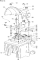
- Fig. 1 schematically illustrates an inner structure of a vehicle lamp 10 according to an embodiment.
- the vehicle lamp 10 is a left-side vehicle headlamp provided in the left end portion of the front end portion of a vehicle body.
- a right-side vehicle headlamp having a shape that is a mirror image of the vehicle lamp 10 is disposed in the right end portion of the front end portion of the vehicle body.
- the left-side vehicle headlamp and the right-side vehicle headlamp have similar structures, and thus the left-side vehicle headlamp will be described as an example, hereinafter.
- the vehicle lamp 10 includes a lamp body 12 having a recess portion that opens frontward and a light-transmissive cover 14 that closes the opening in the lamp body 12.
- the lamp body 12 and the cover 14 constitute a lamp housing 16.
- the inner space of the lamp housing 16 serves as a lamp room 18.
- a light-emitting unit 20, an extension 22, and an optical member 24 are disposed in the lamp room 18.
- the optical member 24 is provided to condense or focus the light emitted from the light-emitting unit 20.
- the optical member 24 is, for example, a convex lens, a projection lens, a condenser lens, a light guide, a cylindrical lens, or the like.
- the light-emitting unit 20 includes a laser light source 26, a light source base 28 that supports the laser light source 26, a heat-dissipating member (hereinafter, also referred to as a heat sink) 30 to which the light source base 28 is attached, and a reflector 32 that reflects the light from the laser light source 26 toward the front of the lamp.
- a positioning structure 34 is provided in the light source base 28 for positioning the reflector 32 relative to the laser light source 26. The light-emitting unit 20 and the positioning structure 34 will be described later in detail.
- the heat sink 30 is attached to a metal support member 40 at a substantially middle portion thereof.
- a first aiming screw 42 is attached to an upper portion of the metal support member 40, and a second aiming screw 44 is attached to a lower portion of the metal support member 40.
- the metal support member 40 is supported by the first aiming screw 42 and the second aiming screw 44 so as to be tiltable relative to the lamp body 12. Then, rotating the first aiming screw 42 and/or the second aiming screw 44 causes the metal support member 40 to tilt, and the light-emitting unit 20 is tilted along therewith to adjust the optical axis of the illumination light (aiming adjustment).
- the laser light source 26 includes a laser diode 46, which is a type of semiconductor light-emitting element; a condenser lens 48 that condenses the light emitted from the laser diode 46; a housing 50 that houses the laser diode 46 and the condenser lens 48; and an optical wavelength conversion unit 52 provided in a penetrating portion formed in an upper portion of the housing 50.
- the laser diode 46 is provided on a bottom portion of the housing 50.
- One or more blue LDs are arrayed in the laser diode 46.
- a transparent sealing member having yellow phosphor dispersed therein, plate-shaped yellow phosphor ceramics, or the like is used as the optical wavelength conversion unit 52, for example.
- An upper surface of the optical wavelength conversion unit 52 serves as a light-exit surface 54 of the laser light source 26.
- An optical axis 56 of the laser light source 26 extends in a direction along which the emission light of the laser light source 26 is most intense.
- the optical axis 56 passes through the center of the light-exit surface 54 and is perpendicular to the light-exit surface 54.
- the center of the light-exit surface 54 is also referred to as a light source center 57.
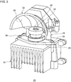
- Fig. 3 is a perspective view schematically illustrating an appearance of the light-emitting unit 20 according to the embodiment.
- Fig. 4 is a perspective view schematically illustrating an appearance of the light source base 28 and the reflector 32 according to the embodiment. To facilitate understanding, the reflector 32 is hatched in Fig. 4 .
- the light source base 28 is directly attached to the heat sink 30 with a bottom plate 29 of the light source base 28 abutting an upper surface of the heat sink 30.
- the light source base 28 is attached to the heat sink 30 with the use of light source base attaching screws 58, but any other attaching unit may be used.
- the reflector 32 has a reflective surface 60 and is disposed outside the laser light source 26 (above the laser light source 26 in the drawings) to receive the light from the light-exit surface 54 with the reflective surface 60.
- the reflective surface 60 opposes the light-exit surface 54.
- the reflector 32 is directly attached to the light source base 28. In the illustrated example, the reflector 32 is attached to the light source base 28 with the use of reflector attaching screws 62, but any other attaching unit may be used.
- a fan (not illustrated) may be attached to a bottom portion of the heat sink 30.
- Fig. 5 is a perspective view schematically illustrating an appearance of the laser light source 26 and the light source base 28 according to the embodiment. To facilitate understanding, positioning surfaces are hatched in Fig. 5 .
- Fig. 6A is a schematic top view of the laser light source 26 and the light source base 28 according to the embodiment
- Fig. 6B is a schematic front view of the laser light source 26 and the light source base 28 according to the embodiment. As illustrated in Fig. 6A and Fig. 6B , an orthogonal coordinate system with the origin lying at the light source center 57 is considered for convenience of description below.
- the front-back direction and the right-left direction of the lamp extend along the X-axis and the Y-axis, respectively, and the optical axis direction extends along the Z-axis.
- the light emitted from the laser light source 26 is deflected by the reflector 32 toward the front in the X-direction.
- a hole into which a feeder terminal of the laser light source 26 is inserted is omitted for convenience.
- Fig. 7 is a schematic bottom view of the reflector 32 according to the embodiment.
- Fig. 8 is a schematic front view of the light source base 28 and the reflector 32 according to the embodiment.
- Fig. 9 is a sectional view along the A-A line indicated in Fig. 8 .
- the positioning structure 34 in the light source base 28 includes a cylindrical first positioning pin 64 and a columnar second positioning pin 66.
- the first positioning pin 64 and the second positioning pin 66 are erected on the bottom plate 29 of the light source base 28 and formed integrally with the light source base 28.
- the light source base 28 is formed substantially symmetric with respect to the X-axis.
- the light source base 28 is a member that holds the laser light source 26 while allowing power to be fed thereto.
- a feeder substrate 68 for feeding power to the laser light source 26 is installed on the light source base 28.
- the center of the first positioning pin 64 coincides with the optical axis 56.
- the position of the center of the second positioning pin 66 in the Y-direction coincides with the position of the center of the first positioning pin 64 in the Y-direction.
- the center of the first positioning pin 64 and the center of the second positioning pin 66 both lie on the X-axis.
- the second positioning pin 66 is disposed more backward than the first positioning pin 64 in the X-direction.
- the first positioning pin 64 defines a first positioning side surface 70 centered at the optical axis 56.
- the first positioning side surface 70 is an outer peripheral surface of the first positioning pin 64.
- the first positioning side surface 70 is used to position the reflector 32 relative to the laser light source 26 in the direction of rotation about the optical axis 56.
- the first positioning pin 64 also defines a first positioning end surface 72.
- the first positioning end surface 72 is an upper surface of the first positioning pin 64 (i.e., the leading end surface in the optical axis direction).
- the first positioning end surface 72 is used to position the reflector 32 relative to the laser light source 26 in the optical axis direction.
- the first positioning end surface 72 is at a first height H1 from the bottom plate 29 of the light source base 28 in the optical axis direction.
- the light-exit surface 54 is at a second height H2 from the bottom plate 29 of the light source base 28 in the optical axis direction.
- the second height H2 is higher than the first height H1. In this manner, the light-exit surface 54 is located higher than the first positioning end surface 72.
- a light source mounting recess portion 74 is formed in the first positioning pin 64 for mounting the laser light source 26 therein.
- a large portion of the laser light source 26 is housed in the light source mounting recess portion 74 except for the light-exit surface 54 and the vicinity thereof.
- the light source mounting recess portion 74 has a larger diameter than the laser light source 26, and a space is present between the inner peripheral surface of the first positioning pin 64 and the outer peripheral surface of the laser light source 26. In this manner, the first positioning pin 64 is formed to enclose the laser light source 26.
- the second positioning pin 66 defines a second positioning side surface 76.
- the second positioning side surface 76 is an outer peripheral surface of the second positioning pin 66.
- the second positioning side surface 76 is used to position the reflector 32 relative to the laser light source 26 in the direction of rotation about the optical axis 56.
- the outer diameter of the second positioning pin 66 is smaller than the outer diameter of the first positioning pin 64.
- the light source base 28 includes two reflector attaching screw hole portions 78.
- the two reflector attaching screw hole portions 78 are disposed on respective sides across the X-axis.
- the reflector attaching screw hole portions 78 are each erected in a columnar shape on the bottom plate 29 of the light source base 28 and formed integrally with the light source base 28.
- a screw hole for the reflector attaching screw 62 (see Fig. 4 ) is formed at the center of each reflector attaching screw hole portion 78.
- the reflector attaching screw hole portions 78 each define a second positioning end surface 80.
- the second positioning end surfaces 80 are upper surfaces of the respective reflector attaching screw hole portions 78.
- the second positioning end surfaces 80 are used to position the reflector 32 relative to the laser light source 26 in the optical axis direction.
- the second positioning end surfaces 80 are a part of the positioning structure 34.
- the second positioning end surfaces 80 are located at the same heightwise position as the first positioning end surface 72 in the optical axis direction.
- Two heat sink attaching screw holes 82 are formed in the bottom plate 29 of the light source base 28.
- the two heat sink attaching screw holes 82 are disposed on respective sides across the X-axis.
- the heat sink attaching screw holes 82 are provided more outward than the reflector attaching screw hole portions 78 in the X-direction.
- the light source base attaching screws 58 (see Fig. 3 ) are inserted into the heat sink attaching screw holes 82.
- the reflector 32 includes an engagement portion 84 that engages with the first positioning pin 64.
- the engagement portion 84 is a circular portion having an opening 85 through which the optical axis 56 passes.
- An upper surface 89 of the engagement portion 84 is located at the same heightwise position as the light-exit surface 54 in the optical axis direction.
- the engagement portion 84 defines a first positioning hole 86 corresponding to the first positioning side surface 70 of the first positioning pin 64.
- the first positioning hole 86 is an inner peripheral surface of the engagement portion 84.
- the engagement portion 84 also defines a first abutment surface 88 that abuts the first positioning end surface 72 of the first positioning pin 64.
- the first abutment surface 88 is a region between the opening 85 and the first positioning hole 86.
- the reflector 32 includes a reflector base portion 83 for supporting the reflector 32.
- the engagement portion 84 is a part of the reflector base portion 83.
- the reflector base portion 83 is coupled to the reflective surface 60 of the reflector 32 at a position backward in the X-direction.
- the reflector base portion 83 can support the reflective surface 60 of the reflector 32 above the laser light source 26.
- the reflector base portion 83 includes a second positioning hole 90 that engages with the second positioning pin 66.
- the second positioning hole 90 is a long hole that can accept the second positioning pin 66 thereinto and is elongated in the X-direction.
- Attaching screw holes 92 are formed in the reflector base portion 83 to correspond to the reflector attaching screw hole portions 78 in the light source base 28.
- the reflector base portion 83 defines second abutment surfaces 94 that abut the second positioning end surfaces 80 around the respective attaching screw holes 92.
- the light source base 28 can position the reflector 32 relative to the laser light source 26 in the direction of rotation about the optical axis 56.
- the light source base 28 can position the reflector 32 relative to the laser light source 26 in the optical axis direction.
- the positioning structure 34 that positions the reflector 32 relative to the laser light source 26 is provided in the light source base 28.
- the laser light source 26 and the reflector 32 are both supported on the light source base 28.
- the light source base 28 is attached to the heat sink 30. Therefore, the reflector 32 is directly fixed to the light source base 28 without the heat sink 30 interposed therebetween.
- an accumulation of dimensional tolerances is considered with the light source center 57 serving as a start point and the diameter of the first positioning hole 86 in the reflector 32 serving as an end point.
- the result of this accumulation reflects a variation in the accuracy of assembling the optical components in the light-emitting unit 20, namely, the accuracy of the optical axis. Since the reflector 32 is directly fixed to the light source base 28, the result of the accumulation of the dimensional tolerances can be kept relatively small. Accordingly, the light-emitting unit 20 with an accuracy-improved optical axis and the vehicle lamp 10 provided with such a light-emitting unit 20 can be provided.
- a light source base and a reflector are each attached to a heat sink.
- the reflector is attached to the light source base with the heat sink interposed therebetween.
- the first positioning pin 64 defines the first positioning side surface 70 centered at the optical axis 56 of the laser light source 26.
- the center of the first positioning pin 64 coincides with the light source center 57.
- This design makes it possible to omit a dimensional tolerance between the center of the first positioning pin 64 and the light source center 57 in the accumulation, and the accuracy of the optical axis can thus be improved.
- the center of the second positioning pin 66 coincides with the light source center 57 in the X-direction. This also helps to improve the accuracy of the optical axis.
- the first positioning pin 64 defines the light source mounting recess portion 74 for mounting the laser light source 26 therein, and the first positioning side surface 70 is the outer peripheral surface of the first positioning pin 64. This configuration makes it possible to dispose the laser light source 26 and the first positioning pin 64 coaxially and to house the laser light source 26 in the light source mounting recess portion 74. Thus, the size of the light source base 28 can be reduced.
- the first positioning pin 64 includes the first positioning end surface 72 located at the first height H1 in the optical axis direction, and the light-exit surface 54 is located at the second height H2 that is higher than the first height H1 in the optical axis direction. In this manner, the height of the leading end surface of the first positioning pin 64 in the optical axis direction is lower than the light-exit surface 54 of the laser light source 26.
- the upper surface 89 of the engagement portion 84 of the reflector 32 can be disposed at the same height as the light-exit surface 54.
- the upper surface 89 of the engagement portion 84 of the reflector 32 can be disposed at a position lower than the height of the light-exit surface 54. Accordingly, the engagement portion 84 does not block the light emitted from the light-exit surface 54 toward the reflector 32.
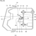
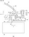
- Fig. 10 schematically illustrates an inner structure of a vehicle lamp 110 according to an embodiment.
- the vehicle lamp 110 is a left-side vehicle headlamp provided in the left end portion of the front end portion of a vehicle body.
- a right-side vehicle headlamp having a shape that is a mirror image of the vehicle lamp 110 is disposed in the right end portion of the front end portion of the vehicle body.
- the left-side vehicle headlamp and the right-side vehicle headlamp have similar structures, and thus the left-side vehicle headlamp will be described as an example, hereinafter.
- the vehicle lamp 110 includes a lamp body 112 having a recess portion that opens frontward and a light-transmissive cover 114 that closes the opening in the lamp body 112.
- the lamp body 112 and the cover 114 constitute a lamp housing 116.
- the inner space of the lamp housing 116 serves as a lamp room 118.
- a light-emitting unit 120, an extension 122, and an optical member 124 are disposed in the lamp room 118.
- the optical member 124 is provided to condense or focus the light emitted from the light-emitting unit 120.
- the optical member 124 is, for example, a convex lens, a projection lens, a condenser lens, a light guide, a cylindrical lens, or the like.
- the light-emitting unit 120 includes a laser light source 126, a light source base 128 that supports the laser light source 126, a heat-dissipating member (hereinafter, also referred to as a heat sink) 130 to which the light source base 128 is attached, and a reflector 132 that reflects the light from the laser light source 126 toward the front of the lamp.
- a heat sink heat-dissipating member
- a positioning structure 134 is provided in the light source base 128 for positioning the reflector 132 relative to the laser light source 126.
- the light-emitting unit 120 includes a reflector tilting mechanism 136 provided on the light source base 128 for allowing the reflector 132 to tilt about each of two different axes relative to the laser light source 126.
- the reflector 132 is attached to the light source base 128 and the heat sink 130 with the reflector tilting mechanism 136 interposed therebetween.
- the positioning structure 134 is also a part of the reflector tilting mechanism 136. The light-emitting unit 120, the positioning structure 134, and the reflector tilting mechanism 136 will be described later in detail.
- the heat sink 130 is attached to a light-emitting unit supporting member 140 at a substantially middle portion thereof.
- the light-emitting unit supporting member 140 may be, for example, a metal bracket.
- a first aiming screw 142 is attached to an upper portion of the light-emitting unit supporting member 140, and a second aiming screw 144 is attached to a lower portion of the light-emitting unit supporting member 140.
- the light-emitting unit supporting member 140 is supported by the first aiming screw 142 and the second aiming screw 144 so as to be tiltable relative to the lamp body 112.
- rotating the first aiming screw 142 and/or the second aiming screw 144 causes the light-emitting unit supporting member 140 to tilt, and the light-emitting unit 120 is tilted along therewith to adjust the optical axis of the illumination light (aiming adjustment).
- the vehicle lamp 110 may be provided with a plurality of light-emitting units 120.
- Heat sinks 130 in the respective light-emitting units 120 may be attached to a common light-emitting unit supporting member 140.
- the optical axis of one light-emitting unit 120 can be adjusted relative to another light-emitting unit 120 with the use of the reflector tilting mechanism 136 of the one light-emitting unit 120.
- the laser light source 126 is suitable for illuminating a far place, and thus the light-emitting unit 120 may be provided to form a high-beam light-distribution pattern.
- the vehicle lamp 110 may further be provided with another light-emitting unit for forming a low-beam light-distribution pattern.
- the reflector tilting mechanism 136 may be used to adjust the optical axis of the light-emitting unit 120 relative to the other light-emitting unit. For example, the optical axis of the light-emitting unit 120 may be adjusted relative to an elbow point in the low-beam light-distribution pattern.
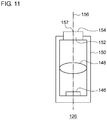
- the laser light source 126 includes a laser diode 146, which is a type of semiconductor light-emitting element; a condenser lens 148 that condenses the light emitted from the laser diode 146; a housing 150 that houses the laser diode 146 and the condenser lens 148; and an optical wavelength conversion unit 152 provided in a penetrating portion formed in an upper portion of the housing 150.
- the laser diode 146 is provided on a bottom portion of the housing 150.
- One or more blue LDs are arrayed in the laser diode 146.
- a transparent sealing member having yellow phosphor dispersed therein, plate-shaped yellow phosphor ceramics, or the like is used as the optical wavelength conversion unit 152, for example.
- An upper surface of the optical wavelength conversion unit 152 serves as a light-exit surface 154 of the laser light source 126.
- An optical axis 156 of the laser light source 126 extends in a direction along which the emission light of the laser light source 126 is most intense.
- the optical axis 156 passes through the center of the light-exit surface 154 and is perpendicular to the light-exit surface 154.
- the center of the light-exit surface 154 is also referred to as a light source center 157.
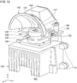
- Fig. 12 is a perspective view schematically illustrating an appearance of the light-emitting unit 120 according to the embodiment.
- Fig. 13 is a schematic exploded perspective view of the light-emitting unit 120 illustrated in Fig. 12 . To facilitate understanding, positioning surfaces are hatched in Fig. 13 .
- Fig. 14 is a schematic sectional view of the light-emitting unit 120 illustrated in Fig. 12 .
- An orthogonal coordinate system with the origin on the light source center 157 is considered for convenience of description below.
- the front-back direction and the right-left direction of the lamp extend along the X-axis and the Y-axis, respectively, and the optical axis direction extends along the Z-axis.
- the light emitted from the laser light source 126 is deflected by the reflector 132 toward the front in the X-direction.
- a section along an XZ-plane is illustrated in Fig. 14 .
- the reflector tilting mechanism 136 is configured to allow the reflector 132 to tilt about a first axis of tilt relative to the laser light source 126 and to allow the reflector 132 to tilt about a second axis of tilt 158 relative to the laser light source 126.
- the first axis of tilt is the optical axis 156 of the laser light source 126.
- the second axis of tilt 158 is orthogonal to the optical axis 156 and is located at the height of the light-exit surface 154 of the laser light source 126.
- the first axis of tilt and the second axis of tilt 158 correspond to the Z-axis and the Y-axis, respectively, and pass through the light source center 157.
- the light source base 128 is directly attached to the heat sink 130 with a bottom plate 129 of the light source base 128 abutting an upper surface of the heat sink 130.
- the light source base 128 is attached to the heat sink 130 with a screw or any other attaching unit.
- the light source base 128 and the heat sink 130 are formed substantially symmetric with respect to the X-axis.
- the heat sink 130 includes boss portions 131 provided at portions toward the back surface in the X-direction, and the boss portions 131 are for fixing the heat sink 130 to a fixing location, such as the light-emitting unit supporting member 140, for example.
- a fan (not illustrated) may be attached to a bottom portion of the heat sink 130.
- the positioning structure 134 in the light source base 128 includes a cylindrical positioning pin 164 having a center coinciding with the optical axis 156.
- the positioning pin 164 is erected on the bottom plate 129 of the light source base 128 and formed integrally with the light source base 128.
- the first positioning pin 164 defines a cylindrical positioning side surface 170 centered at the optical axis 156.
- the positioning side surface 170 is an outer peripheral surface of the positioning pin 164.
- the positioning side surface 170 is used to position the reflector 132 relative to the laser light source 126 in the direction of rotation about the optical axis 156.
- the positioning pin 164 also defines a first positioning end surface 172.
- the first positioning end surface 172 is an upper surface of the positioning pin 164 (i.e., the leading end surface in the optical axis direction) and lies in a plane perpendicular to the optical axis 156.
- the first positioning end surface 172 is used to position the reflector 132 relative to the laser light source 126 in the optical axis direction.
- the first positioning end surface 172 is at a first height H1 from the bottom plate 129 of the light source base 128 in the optical axis direction.
- the light-exit surface 154 is at a second height H2 from the bottom plate 129 of the light source base 128 in the optical axis direction.
- the second height H2 is higher than the first height H1. In this manner, the light-exit surface 154 is located higher than the first positioning end surface 172.
- a light source mounting recess portion 174 is formed in the positioning pin 164 for mounting the laser light source 126 therein.
- a large portion of the laser light source 126 is housed in the light source mounting recess portion 174 except for the light-exit surface 154 and the vicinity thereof.
- the light source mounting recess portion 174 has a larger diameter than the laser light source 126, and a space is present between the inner peripheral surface of the positioning pin 164 and the outer peripheral surface of the laser light source 126. In this manner, the positioning pin 164 is formed to enclose the laser light source 126. This configuration makes it possible to dispose the laser light source 126 and the positioning pin 164 coaxially and to house the laser light source 126 in the light source mounting recess portion 174. Thus, the size of the light source base 128 can be reduced.
- the light source base 128 is a member that holds the laser light source 126 while allowing power to be fed thereto.
- a feeder substrate 168 for feeding power to the laser light source 126 is installed on the light source base 128.
- the heat sink 130 includes two reflector base attachment portions 178.
- the two reflector base attachment portions 178 are disposed on respective sides across the X-axis.
- the reflector base attachment portions 178 are disposed more backward than the positioning pin 164 in the X-direction.
- the reflector base attachment portions 178 each define a second positioning end surface 180.
- the second positioning end surfaces 180 are each formed to enclose a screw hole 179 in the reflector base attachment portion 178.
- the second positioning end surfaces 180 are a part of upper surfaces of the respective reflector base attachment portions 178 and lie in a plane perpendicular to the optical axis 156.
- the second positioning end surfaces 180 are located at the same heightwise position as the first positioning end surface 172 in the optical axis direction. Since the reflector base attachment portions 178 are located more backward than the positioning pin 164 in the X-direction, the second positioning end surfaces 180 are located also more backward than the positioning pin 164 in the X-direction.
- the second positioning end surfaces 180 are used to position the reflector 132 relative to the laser light source 126 in the optical axis direction. As such, the second positioning end surfaces 180 are a part of the positioning structure 134.
- the reflector tilting mechanism 136 includes a reflector base 138 for supporting the reflector 132.
- An engagement portion 184 having a circular lid shape is formed in the reflector base 138 at a front middle portion thereof in the X-direction, and the engagement portion 184 engages with the positioning pin 164.
- the reflector base 138 is a substantially rectangular plate member, and a front semicircular portion of the engagement portion 184 in the X-direction projects frontward from the plate member in the X-direction.
- An upper surface 189 of the engagement portion 184 is located at the same heightwise position as the light-exit surface 154 in the optical axis direction.
- the engagement portion 184 has a cylindrical inner peripheral surface corresponding to the positioning side surface 170 of the positioning pin 164 and an annular planar surface corresponding to the first positioning end surface 172.
- the annular planar surface of the engagement portion 184 is a back surface opposite to the upper surface 189 of the engagement portion 184.
- the reflector base 138 includes two arc-shaped groove portions 160 disposed to correspond to the respective reflector base attachment portions 178.
- the two arc-shaped groove portions 160 are formed along a single arc centered at the light source center 157.
- outer peripheral portions of the arc-shaped groove portions 160 make contact with the respective second positioning end surfaces 180 on a back surface of the reflector base 138, and the arc-shaped groove portions 160 communicate with the screw holes 179 in the respective reflector base attachment portions 178.
- Rotating the engagement portion 184 about the optical axis 156 relative to the positioning pin 164 allows the reflector base 138 and the reflector 132 supported by the reflector base 138 to tilt about the optical axis 156 relative to the laser light source 126.
- the reflector tilting mechanism 136 is provided on the light source base 128 to allow the reflector 132 to tilt about the optical axis 156 relative to the laser light source 126.
- Appropriately selecting an installation angle of the reflector 132 about the optical axis 156 relative to the laser light source 126 within an arc length of the arc-shaped groove portions 160 allows the optical axis of the light-emitting unit 120 to be adjusted in the Y-direction (i.e., the right-left direction of the lamp).
- the reflector base 138 is positioned in the optical axis direction by the first positioning end surface 172 and the second positioning end surfaces 180.
- reflector base attaching screws 162 are inserted into the respective arc-shaped groove portions 160 from the upper surface side of the reflector base 138 and attached into the screw holes 179 in the reflector base attachment portions 178. In this manner, the reflector base 138 is fixed to the light source base 128 and the heat sink 130.
- the number of the reflector base attachment portions 178 and of the arc-shaped groove portions 160 is not limited to two each. One each or three or more each of the reflector base attachment portions 178 and the arc-shaped groove portions 160 may be provided.
- the engagement portion 184 includes an opening 185 through which the optical axis 156 passes.
- the light emitted from the light-exit surface 154 of the laser light source 126 passes through the opening 185 and travels toward the reflector 132.
- the light reflected by the reflector 132 is directed toward the front in the X-direction.
- the opening 185 has a diameter B that is smaller than a diameter C of the laser light source 126.
- the laser light source 126 can be prevented from falling out of the light source mounting recess portion 174 through the opening 185.
- the reflector base 138 supports the reflector 132, allowing the reflector 132 to tilt about the second axis of tilt 158.
- the reflector tilting mechanism 136 includes two coupling portions 182 and an adjustment portion 183.
- the coupling portions 182 couple the reflector 132 to the reflector base 138, allowing the reflector 132 to tilt about the second axis of tilt 158.
- the adjustment portion 183 is configured to be capable of adjusting the gap between the reflector 132 and the reflector base 138.
- the two coupling portions 182 are disposed on respective sides across the X-axis.
- the coupling portions 182 each include a shaft 186 that is disposed in the second axis of tilt 158 and extends along the second axis of tilt 158, and the coupling portions 182 are therefore located at respective sides of the engagement portion 184.
- the shafts 186 are each inserted in a first shaft insertion hole 187 in the reflector base 138 and a second shaft insertion hole 188 in the reflector 132.
- a pair of E rings 190 are attached to the shafts 186 so as to sandwich, from the two sides, the first shaft insertion holes 187 and the second shaft insertion holes 188 in which the shafts 186 are being inserted. In this manner, the coupling portions 182 couple the reflector 132 to the reflector base 138, allowing the reflector 132 to rotate about the shafts 186 relative to the reflector base 138.
- the adjustment portion 183 is disposed at a position offset from the second axis of tilt 158. As illustrated, the adjustment portion 183 couples the reflector 132 to the reflector base 138 at a position more backward than the coupling portions 182 in the X-direction.
- the adjustment portion 183 includes an adjustment screw 91, a spring 192, and an adjustment screw hole portion 193.
- the adjustment screw hole portion 193 is provided in the reflector base 138.
- the adjustment screw 91 is inserted into an adjustment screw insertion hole 194 in the reflector 132 in the optical axis direction and attached into a screw hole of the adjustment screw hole portion 193.
- the spring 192 is disposed between the reflector 132 and the reflector base 138 along the adjustment screw 91 to retain the gap between the reflector 132 and the reflector base 138.
- the gap between the reflector 132 and the reflector base 138 in the optical axis direction is adjusted as the adjustment screw 91 is rotated. Since the reflector 132 is coupled to the reflector base 138 with the coupling portions 182, the reflector 132 can be tilted about the second axis of tilt 158 relative to the reflector base 138. Thus, the optical axis of the light-emitting unit 120 can be adjusted in the Z-direction (i.e., the up-down direction of the lamp).
- the reflector tilting mechanism 136 that can tilt about two different axes is provided on the light source base 128 of the light-emitting unit 120. Accordingly, the angle of the reflector 132 relative to the laser light source 126 can be adjusted in each of the two axes in a state in which the light-emitting unit 120 is attached to a predetermined location, such as the light-emitting unit supporting member 140. In this manner, the optical axis of the light-emitting unit 120 can be finely adjusted, and the accuracy of the optical axis of the light-emitting unit 120 can be improved.
- the first axis of tilt i.e., the optical axis 156) and the second axis of tilt 158 correspond to the Z-axis and the Y-axis, respectively, and pass through the light source center 157.
- the center of rotation of the reflector tilting mechanism 136 coincides with the light source center 157. Accordingly, the optical axis of the light-emitting unit 120 can be adjusted while an influence on the light distribution is kept to a minimum.
- the positioning pin 164 defines the positioning side surface 170 centered at the optical axis 156 of the laser light source 126. In other words, the center of the positioning pin 164 coincides with the light source center 157.
- This design makes it possible to omit the dimensional tolerance between the center of the positioning pin 164 and the light source center 157 when considering an accumulation of the dimensional tolerances. This also helps to improve the accuracy of the optical axis.
- the positioning pin 164 includes the first positioning end surface 172 located at the first height H1 in the optical axis direction, and the light-exit surface 154 is located at the second height H2 that is higher than the first height H1 in the optical axis direction. In this manner, the height of the leading end surface of the positioning pin 164 in the optical axis direction is lower than the light-exit surface 154 of the laser light source 126.
- the upper surface 189 of the engagement portion 184 of the reflector 132 can be disposed at the same height as the light-exit surface 154.
- the upper surface 189 of the engagement portion 184 of the reflector 132 can be disposed at a position lower than the height of the light-exit surface 154. Accordingly, the engagement portion 184 does not block the light emitted from the light-exit surface 154 toward the reflector 132.
- the laser light sources 26 and 126 have a columnar shape, but the light source may have any shape.
- the laser light sources 26 and 126 may have a prism shape or any other prismoidal shape or may have a flat shape such as a baseplate shape.
- the laser light sources 26 and 126 including the laser diodes 46 and 146, respectively, are used as a light source, but this is not a limiting example.
- the light-emitting units 20 and 120 may include a light source including other semiconductor light-emitting element such as a light-emitting diode (LED).
- LED light-emitting diode
- Fig. 15 illustrates an LED light source 95 that can be employed in the light-emitting units 20 and 120.
- the LED light source 95 includes a substrate 96, an LED chip 97 mounted on the substrate 96, and a fluorescent layer 98 provided on the LED chip 97.
- One or more blue LEDs, for example, are arrayed in the LED chip 97.
- An optical wavelength conversion member such as a transparent sealing member having yellow phosphor dispersed therein or plate-shaped yellow phosphor ceramics, is used as the fluorescent layer 98, for example.
- an upper surface of the fluorescent layer 98 serves as a light-exit surface 54.
- An optical axis 56 extends in a direction along which the emission light of the LED light source 95 is most intense. In addition, the optical axis 56 passes through the center of the light-exit surface 54 (i.e., a light source center 57) and is perpendicular to the light-exit surface 54.
- the positioning structures 34 and 134 include a cylindrical or columnar positioning pin, but the shape of the positioning pin is not limited thereto.
- the positioning pin may have a rectangular tubular shape, a prism shape, or any other shape.
- the positioning surface of a tubular positioning pin (e.g., the first positioning pin 64, the positioning pin 164) is not limited to the outer peripheral surface of the tubular positioning pin and may be the inner peripheral surface thereof.
- the engagement portion of the optical member e.g., the reflector 32, the reflector base 138
- the tubular positioning pin need not be continuous along the entire circumference in the circumferential direction about the optical axis 56 or 156.
- the tubular positioning pin may have one or more slits extending in the optical axis direction.
- the tubular positioning pin may be a plurality of projections arrayed to surround the optical axis 56 or 156.
- the tubular positioning pin or the positioning structure may be a tubular positioning pin or a positioning structure having any shape as long as the tubular positioning pin or the positioning structure can define a positioning surface.
- Fig. 16A is a schematic perspective view illustrating a first positioning pin 64 provided with slits
- Fig. 16B illustrates transport of the laser light source 26.
- the X-axis, the Y-axis, and the Z-axis are illustrated in Fig. 16A .
- the outer peripheral surface of the first positioning pin 64 serves as a first positioning side surface 70, and the first positioning pin 64 is erected on the bottom plate 29 of the light source base 28.
- the first positioning pin 64 is tubular and has a light source mounting recess portion 74 defined thereinside.
- slits 64a are formed in the first positioning pin 64.
- the slits 64a are provided at an equal interval in the circumferential direction.
- the three slits 64a split the first positioning pin 64 into three projections arrayed to surround the optical axis 56. As such, a first positioning end surface 72 is also split into three by the slits 64a.
- the first positioning pin 64 has an annular base portion 64b provided on the bottom plate 29 of the light source base 28, and the three projections project along the optical axis 56 from the base portion 64b.
- the first positioning pin 64 need not include the base portion 64b, and the three projections may project from the bottom plate 29 of the light source base 28.
- Fig. 16B illustrates how the laser light source 26 is transported by a mounting device 99.
- the laser light source 26 is transported to the light source base 28 by the mounting device 99 and mounted into the light source mounting recess portion 74 in the first positioning pin 64.
- the mounting device 99 includes three claw chucks 99a for holding the laser light source 26.
- the three claw chucks 99a are disposed to correspond to the three slits 64a described above (i.e., the three claw chucks 99a are disposed at an equal angular interval to surround the laser light source 26), and thus the three claw chucks 99a do not make contact with the first positioning pin 64 when the laser light source 26 is mounted into the light source mounting recess portion 74.
- the mounting device 99 Upon the laser light source 26 being mounted in the light source mounting recess portion 74, the mounting device 99 releases the claw chucks 99a. In this manner, the mounting device 99 can position the laser light source 26 relative to the light source base 28 in the Z-direction without the claw chucks 99a interfering with the first positioning pin 64.
- the laser light source 26 includes a feeder terminal 26a provided on a bottom portion thereof.
- the light source base 28 includes an insertion hole 29a into which the feeder terminal 26a of the laser light source 26 is inserted.
- the insertion hole 29a penetrates the bottom plate 29 of the light source base 28 from the light source mounting recess portion 74 to the back surface of the bottom plate 29.
- the feeder terminal 26a of the laser light source 26 is inserted into the insertion hole 29a.
- the feeder terminal 26a of the laser light source 26 is connected to a feeder unit at a back surface side of the bottom plate 29 of the light source base 28.
- Such an insertion hole 29a may be provided in the light source base 28 similarly in the embodiments described with reference to Fig. 1 to Fig. 15 .
- the number of the claw chucks 99a of the mounting device 99 is desirably three or more.
- the slits 64a are formed in the first positioning pin 64 desirably in the same number as the number of the claw chucks 99a.
- the first positioning pin 64 may have four slits 64a.
- the slits 64a may be provided in the positioning pin 164.
- the optical member that is positioned relative to the light source by the positioning structure is not limited to the reflector 32.
- the optical member may be other optical members such as a lens.
- the optical member that is allowed to tilt relative to the light source by the tilting mechanism is not limited to the reflector 132.
- the optical member may be other optical members such as a lens.
- the light-emitting unit 120 includes the light source base 128 serving as a light source supporting member, and the heat sink 130 is provided as a member separate from the light source base 128, but this is not a limiting example.
- a light-emitting unit may include a light source supporting member in which a light source base and a heat-dissipating member are integrated.
- the positioning structure 34 may include the reflector tilting mechanism 136.
- the optical member positioning structure may include an optical member tilting mechanism configured to allow an optical member to tilt about each of two different axes relative to a light source.
- the present invention can be used in light-emitting units and vehicle lamps.
Description
- The present invention relates to a light-emitting unit according to claim 1 and a vehicle lamp comprising such light-emitting unit according to claim 6.
- To date, light source units provided with semiconductor laser light sources and for use in vehicle headlamps have been conceived (see, for example, patent document 1).
- [patent document 1]
JP2013-38010 - [patent document 2]
JP2008-108613 - [patent document 3]
US2015/204503 discloses a light-emitting device for a motor vehicle exhibiting the features of the preamble of claim 1. - The position of an optical axis in an actual product may differ from the position according to the design within a range of various tolerances, such as an accuracy of assembling optical components. Such a positional deviation of an optical axis is very small but, in a strict sense, leads to an error in the irradiation position of the light from the vehicle lamp. A semiconductor laser light source has a high luminance and can illuminate a far place, and thus a slight deviation of the optical axis can result in a relatively large error in the irradiation position. It is desired that the optical axis be as highly accurate as possible also in light sources provided with other semiconductor light-emitting elements.
- The present invention has been made to address such a situation and is directed to providing a light-emitting unit with an accuracy-improved optical axis and a vehicle lamp provided with such a light-emitting unit.
- To solve the problem described above, a light-emitting unit according to an aspect of the present invention includes a light source including a semiconductor light-emitting element, a light source base that supports the light source, a heat-dissipating member to which the light source base is attached, and an optical member. The light source base includes an optical member positioning structure that positions the optical member relative to the light source.
- A light-emitting unit according to the present invention includes a light source exhibiting the characterizing features of claim 1.
- According to this aspect, the light source supporting member is provided with the optical member tilting mechanism. Therefore, a positional deviation of an optical axis can be corrected by tilting the optical member relative to the light source with the use of the optical member tilting mechanism after the light-emitting unit is attached to a predetermined location. Accordingly, the accuracy of the optical axis of the light-emitting unit can be improved.
- The optical member tilting mechanism may be configured to allow the optical member to tilt about a first axis of tilt relative to the light source and to allow the optical member to tilt about a second axis of tilt relative to the light source, the first axis of tilt may be an optical axis of the light source, and the second axis of tilt may be orthogonal to the optical axis and located at a height of a light-exit surface of the light source.
- The positioning structure may include a leading end surface located at a first height in an optical axis direction, and a light-exit surface of the light source may be located at a second height higher than the first height in the optical axis direction.
- The light source supporting member may include a light source base that supports the light source, and a heat-dissipating member to which the light source base is attached or that is formed integrally with the light source base.
- The positioning structure may include a positioning pin provided with a slit.
- A vehicle lamp may include the light-emitting unit described above.
- According to the present invention, a light-emitting unit with an accuracy-improved optical axis and a vehicle lamp provided with such a light-emitting unit can be provided.
-
-
Fig. 1 schematically illustrates an inner structure of a vehicle lamp according to a first embodiment; -
Fig. 2 schematically illustrates an inner structure of a laser light source according to the first embodiment; -
Fig. 3 is a perspective view schematically illustrating an appearance of a light-emitting unit according to the first embodiment; -
Fig. 4 is a perspective view schematically illustrating an appearance of a light source base and a reflector according to the first embodiment; -
Fig. 5 is a perspective view schematically illustrating an appearance of the laser light source and the light source base according to the first embodiment; -
Fig. 6A is a schematic top view of the laser light source and the light source base according to the first embodiment, andFig. 6B is a schematic front view of the laser light source and the light source base according to the first embodiment; -
Fig. 7 is a schematic bottom view of the reflector according to the first embodiment; -
Fig. 8 is a schematic front view of the light source base and the reflector according to the first embodiment; -
Fig. 9 is a sectional view along the A-A line indicated inFig. 8 ; -
Fig. 10 schematically illustrates an inner structure of a vehicle lamp according to a second embodiment; -
Fig. 11 schematically illustrates an inner structure of a laser light source according to the second embodiment; -
Fig. 12 is a perspective view schematically illustrating an appearance of a light-emitting unit according to the second embodiment; -
Fig. 13 is a schematic exploded perspective view of the light-emitting unit illustrated inFig. 12 ; -
Fig. 14 is a schematic sectional view of the light-emitting unit illustrated inFig. 12 ; -
Fig. 15 illustrates another light source that can be employed in a light-emitting unit; and -
Fig. 16A is a schematic perspective view illustrating a first positioning pin provided with slits, andFig. 16B illustrates transport of the laser light source. - Hereinafter, the present invention will be described on the basis of exemplary embodiments with reference to the drawings. The embodiments are illustrative in nature and are not intended to limit the invention. Not all the features and combinations thereof described in the embodiments are necessarily essential to the invention. Identical or equivalent constituent elements, members, and processes illustrated in the drawings are given identical reference characters, and duplicate descriptions thereof will be omitted as appropriate. The scales and the shapes of the components illustrated in the drawings are set merely for convenience to facilitate the descriptions and are not to be interpreted as limiting the invention, unless specifically indicated otherwise.
-
Fig. 1 schematically illustrates an inner structure of avehicle lamp 10 according to an embodiment. Thevehicle lamp 10 is a left-side vehicle headlamp provided in the left end portion of the front end portion of a vehicle body. A right-side vehicle headlamp having a shape that is a mirror image of thevehicle lamp 10 is disposed in the right end portion of the front end portion of the vehicle body. The left-side vehicle headlamp and the right-side vehicle headlamp have similar structures, and thus the left-side vehicle headlamp will be described as an example, hereinafter. - The
vehicle lamp 10 includes alamp body 12 having a recess portion that opens frontward and a light-transmissive cover 14 that closes the opening in thelamp body 12. Thelamp body 12 and thecover 14 constitute alamp housing 16. The inner space of thelamp housing 16 serves as alamp room 18. - A light-
emitting unit 20, anextension 22, and anoptical member 24 are disposed in thelamp room 18. Theoptical member 24 is provided to condense or focus the light emitted from the light-emittingunit 20. Theoptical member 24 is, for example, a convex lens, a projection lens, a condenser lens, a light guide, a cylindrical lens, or the like. - The light-emitting
unit 20 includes alaser light source 26, alight source base 28 that supports thelaser light source 26, a heat-dissipating member (hereinafter, also referred to as a heat sink) 30 to which thelight source base 28 is attached, and areflector 32 that reflects the light from thelaser light source 26 toward the front of the lamp. Apositioning structure 34 is provided in thelight source base 28 for positioning thereflector 32 relative to thelaser light source 26. The light-emittingunit 20 and thepositioning structure 34 will be described later in detail. - The
heat sink 30 is attached to ametal support member 40 at a substantially middle portion thereof. A first aimingscrew 42 is attached to an upper portion of themetal support member 40, and a second aimingscrew 44 is attached to a lower portion of themetal support member 40. Themetal support member 40 is supported by the first aimingscrew 42 and the second aimingscrew 44 so as to be tiltable relative to thelamp body 12. Then, rotating the first aimingscrew 42 and/or the second aimingscrew 44 causes themetal support member 40 to tilt, and the light-emittingunit 20 is tilted along therewith to adjust the optical axis of the illumination light (aiming adjustment). -
Fig. 2 schematically illustrates an inner structure of thelaser light source 26 according to the embodiment. Thelaser light source 26 includes alaser diode 46, which is a type of semiconductor light-emitting element; acondenser lens 48 that condenses the light emitted from thelaser diode 46; ahousing 50 that houses thelaser diode 46 and thecondenser lens 48; and an opticalwavelength conversion unit 52 provided in a penetrating portion formed in an upper portion of thehousing 50. Thelaser diode 46 is provided on a bottom portion of thehousing 50. One or more blue LDs, for example, are arrayed in thelaser diode 46. A transparent sealing member having yellow phosphor dispersed therein, plate-shaped yellow phosphor ceramics, or the like is used as the opticalwavelength conversion unit 52, for example. An upper surface of the opticalwavelength conversion unit 52 serves as a light-exit surface 54 of thelaser light source 26. - An
optical axis 56 of thelaser light source 26 extends in a direction along which the emission light of thelaser light source 26 is most intense. In addition, theoptical axis 56 passes through the center of the light-exit surface 54 and is perpendicular to the light-exit surface 54. In the present specification, for convenience of description, the center of the light-exit surface 54 is also referred to as alight source center 57. -
Fig. 3 is a perspective view schematically illustrating an appearance of the light-emittingunit 20 according to the embodiment.Fig. 4 is a perspective view schematically illustrating an appearance of thelight source base 28 and thereflector 32 according to the embodiment. To facilitate understanding, thereflector 32 is hatched inFig. 4 . - The
light source base 28 is directly attached to theheat sink 30 with abottom plate 29 of thelight source base 28 abutting an upper surface of theheat sink 30. In the illustrated example, thelight source base 28 is attached to theheat sink 30 with the use of light sourcebase attaching screws 58, but any other attaching unit may be used. - The
reflector 32 has areflective surface 60 and is disposed outside the laser light source 26 (above thelaser light source 26 in the drawings) to receive the light from the light-exit surface 54 with thereflective surface 60. Thereflective surface 60 opposes the light-exit surface 54. Thereflector 32 is directly attached to thelight source base 28. In the illustrated example, thereflector 32 is attached to thelight source base 28 with the use ofreflector attaching screws 62, but any other attaching unit may be used. - A fan (not illustrated) may be attached to a bottom portion of the
heat sink 30. -
Fig. 5 is a perspective view schematically illustrating an appearance of thelaser light source 26 and thelight source base 28 according to the embodiment. To facilitate understanding, positioning surfaces are hatched inFig. 5 .Fig. 6A is a schematic top view of thelaser light source 26 and thelight source base 28 according to the embodiment, andFig. 6B is a schematic front view of thelaser light source 26 and thelight source base 28 according to the embodiment. As illustrated inFig. 6A and Fig. 6B , an orthogonal coordinate system with the origin lying at thelight source center 57 is considered for convenience of description below. In other words, the front-back direction and the right-left direction of the lamp extend along the X-axis and the Y-axis, respectively, and the optical axis direction extends along the Z-axis. The light emitted from thelaser light source 26 is deflected by thereflector 32 toward the front in the X-direction. InFig. 6A , a hole into which a feeder terminal of thelaser light source 26 is inserted is omitted for convenience. -
Fig. 7 is a schematic bottom view of thereflector 32 according to the embodiment.Fig. 8 is a schematic front view of thelight source base 28 and thereflector 32 according to the embodiment.Fig. 9 is a sectional view along the A-A line indicated inFig. 8 . - The
positioning structure 34 in thelight source base 28 includes a cylindricalfirst positioning pin 64 and a columnarsecond positioning pin 66. Thefirst positioning pin 64 and thesecond positioning pin 66 are erected on thebottom plate 29 of thelight source base 28 and formed integrally with thelight source base 28. Thelight source base 28 is formed substantially symmetric with respect to the X-axis. - The
light source base 28 is a member that holds thelaser light source 26 while allowing power to be fed thereto. Afeeder substrate 68 for feeding power to thelaser light source 26 is installed on thelight source base 28. - The center of the
first positioning pin 64 coincides with theoptical axis 56. The position of the center of thesecond positioning pin 66 in the Y-direction coincides with the position of the center of thefirst positioning pin 64 in the Y-direction. In other words, the center of thefirst positioning pin 64 and the center of thesecond positioning pin 66 both lie on the X-axis. Thesecond positioning pin 66 is disposed more backward than thefirst positioning pin 64 in the X-direction. - The
first positioning pin 64 defines a firstpositioning side surface 70 centered at theoptical axis 56. The firstpositioning side surface 70 is an outer peripheral surface of thefirst positioning pin 64. The firstpositioning side surface 70 is used to position thereflector 32 relative to thelaser light source 26 in the direction of rotation about theoptical axis 56. - The
first positioning pin 64 also defines a firstpositioning end surface 72. The firstpositioning end surface 72 is an upper surface of the first positioning pin 64 (i.e., the leading end surface in the optical axis direction). The firstpositioning end surface 72 is used to position thereflector 32 relative to thelaser light source 26 in the optical axis direction. - As illustrated in
Fig. 9 , the firstpositioning end surface 72 is at a first height H1 from thebottom plate 29 of thelight source base 28 in the optical axis direction. The light-exit surface 54 is at a second height H2 from thebottom plate 29 of thelight source base 28 in the optical axis direction. The second height H2 is higher than the first height H1. In this manner, the light-exit surface 54 is located higher than the firstpositioning end surface 72. - A light source mounting
recess portion 74 is formed in thefirst positioning pin 64 for mounting thelaser light source 26 therein. A large portion of thelaser light source 26 is housed in the light source mountingrecess portion 74 except for the light-exit surface 54 and the vicinity thereof. The light source mountingrecess portion 74 has a larger diameter than thelaser light source 26, and a space is present between the inner peripheral surface of thefirst positioning pin 64 and the outer peripheral surface of thelaser light source 26. In this manner, thefirst positioning pin 64 is formed to enclose thelaser light source 26. - Referring again to
Fig. 5 ,Fig. 6A, and Fig. 6B , thesecond positioning pin 66 defines a secondpositioning side surface 76. The secondpositioning side surface 76 is an outer peripheral surface of thesecond positioning pin 66. The secondpositioning side surface 76 is used to position thereflector 32 relative to thelaser light source 26 in the direction of rotation about theoptical axis 56. The outer diameter of thesecond positioning pin 66 is smaller than the outer diameter of thefirst positioning pin 64. - The
light source base 28 includes two reflector attachingscrew hole portions 78. The two reflector attachingscrew hole portions 78 are disposed on respective sides across the X-axis. The reflector attachingscrew hole portions 78 are each erected in a columnar shape on thebottom plate 29 of thelight source base 28 and formed integrally with thelight source base 28. A screw hole for the reflector attaching screw 62 (seeFig. 4 ) is formed at the center of each reflector attachingscrew hole portion 78. - The reflector attaching
screw hole portions 78 each define a secondpositioning end surface 80. The second positioning end surfaces 80 are upper surfaces of the respective reflector attachingscrew hole portions 78. The second positioning end surfaces 80 are used to position thereflector 32 relative to thelaser light source 26 in the optical axis direction. As such, the second positioning end surfaces 80 are a part of thepositioning structure 34. The second positioning end surfaces 80 are located at the same heightwise position as the firstpositioning end surface 72 in the optical axis direction. - Two heat sink attaching screw holes 82 are formed in the
bottom plate 29 of thelight source base 28. The two heat sink attaching screw holes 82 are disposed on respective sides across the X-axis. The heat sink attaching screw holes 82 are provided more outward than the reflector attachingscrew hole portions 78 in the X-direction. The light source base attaching screws 58 (seeFig. 3 ) are inserted into the heat sink attaching screw holes 82. - As illustrated in
Fig. 7 to Fig. 9 , thereflector 32 includes anengagement portion 84 that engages with thefirst positioning pin 64. Theengagement portion 84 is a circular portion having anopening 85 through which theoptical axis 56 passes. In other words, the light emitted from the light-exit surface 54 passes through theopening 85 and travels toward thereflective surface 60 of thereflector 32. Anupper surface 89 of theengagement portion 84 is located at the same heightwise position as the light-exit surface 54 in the optical axis direction. - The
engagement portion 84 defines afirst positioning hole 86 corresponding to the firstpositioning side surface 70 of thefirst positioning pin 64. Thefirst positioning hole 86 is an inner peripheral surface of theengagement portion 84. Theengagement portion 84 also defines afirst abutment surface 88 that abuts the firstpositioning end surface 72 of thefirst positioning pin 64. Thefirst abutment surface 88 is a region between theopening 85 and thefirst positioning hole 86. - The
reflector 32 includes areflector base portion 83 for supporting thereflector 32. Theengagement portion 84 is a part of thereflector base portion 83. Thereflector base portion 83 is coupled to thereflective surface 60 of thereflector 32 at a position backward in the X-direction. When theengagement portion 84 is disposed to cover thefirst positioning pin 64, thereflector base portion 83 can support thereflective surface 60 of thereflector 32 above thelaser light source 26. - The
reflector base portion 83 includes asecond positioning hole 90 that engages with thesecond positioning pin 66. Thesecond positioning hole 90 is a long hole that can accept thesecond positioning pin 66 thereinto and is elongated in the X-direction. - Attaching screw holes 92 are formed in the
reflector base portion 83 to correspond to the reflector attachingscrew hole portions 78 in thelight source base 28. Thereflector base portion 83 defines second abutment surfaces 94 that abut the second positioning end surfaces 80 around the respective attaching screw holes 92. - As the
first positioning hole 86 and thesecond positioning hole 90 engage with thefirst positioning pin 64 and thesecond positioning pin 66, respectively, thelight source base 28 can position thereflector 32 relative to thelaser light source 26 in the direction of rotation about theoptical axis 56. - As the
first abutment surface 88 and the second abutment surfaces 94 abut the firstpositioning end surface 72 and the second positioning end surfaces 80, respectively, thelight source base 28 can position thereflector 32 relative to thelaser light source 26 in the optical axis direction. - As described thus far, the
positioning structure 34 that positions thereflector 32 relative to thelaser light source 26 is provided in thelight source base 28. In other words, thelaser light source 26 and thereflector 32 are both supported on thelight source base 28. Thelight source base 28 is attached to theheat sink 30. Therefore, thereflector 32 is directly fixed to thelight source base 28 without theheat sink 30 interposed therebetween. - In evaluating the accuracy of the optical axis of the light-emitting
unit 20, an accumulation of dimensional tolerances is considered with thelight source center 57 serving as a start point and the diameter of thefirst positioning hole 86 in thereflector 32 serving as an end point. The result of this accumulation reflects a variation in the accuracy of assembling the optical components in the light-emittingunit 20, namely, the accuracy of the optical axis. Since thereflector 32 is directly fixed to thelight source base 28, the result of the accumulation of the dimensional tolerances can be kept relatively small. Accordingly, the light-emittingunit 20 with an accuracy-improved optical axis and thevehicle lamp 10 provided with such a light-emittingunit 20 can be provided. - In contrast, in a typical light-emitting unit, a light source base and a reflector are each attached to a heat sink. In this case, the reflector is attached to the light source base with the heat sink interposed therebetween. When an accumulation of dimensional tolerances is considered in a similar manner with a light source center serving as a start point and the diameter of a positioning hole in the reflector serving as an end point, the result of the accumulation of the dimensional tolerances becomes relatively large in this typical configuration since the heat sink is interposed therebetween.
- Furthermore, the
first positioning pin 64 defines the firstpositioning side surface 70 centered at theoptical axis 56 of thelaser light source 26. In other words, the center of thefirst positioning pin 64 coincides with thelight source center 57. This design makes it possible to omit a dimensional tolerance between the center of thefirst positioning pin 64 and thelight source center 57 in the accumulation, and the accuracy of the optical axis can thus be improved. In addition, the center of thesecond positioning pin 66 coincides with thelight source center 57 in the X-direction. This also helps to improve the accuracy of the optical axis. - The
first positioning pin 64 defines the light source mountingrecess portion 74 for mounting thelaser light source 26 therein, and the firstpositioning side surface 70 is the outer peripheral surface of thefirst positioning pin 64. This configuration makes it possible to dispose thelaser light source 26 and thefirst positioning pin 64 coaxially and to house thelaser light source 26 in the light source mountingrecess portion 74. Thus, the size of thelight source base 28 can be reduced. - The
first positioning pin 64 includes the firstpositioning end surface 72 located at the first height H1 in the optical axis direction, and the light-exit surface 54 is located at the second height H2 that is higher than the first height H1 in the optical axis direction. In this manner, the height of the leading end surface of thefirst positioning pin 64 in the optical axis direction is lower than the light-exit surface 54 of thelaser light source 26. Thus, theupper surface 89 of theengagement portion 84 of thereflector 32 can be disposed at the same height as the light-exit surface 54. Alternatively, theupper surface 89 of theengagement portion 84 of thereflector 32 can be disposed at a position lower than the height of the light-exit surface 54. Accordingly, theengagement portion 84 does not block the light emitted from the light-exit surface 54 toward thereflector 32. -
Fig. 10 schematically illustrates an inner structure of avehicle lamp 110 according to an embodiment. Thevehicle lamp 110 is a left-side vehicle headlamp provided in the left end portion of the front end portion of a vehicle body. A right-side vehicle headlamp having a shape that is a mirror image of thevehicle lamp 110 is disposed in the right end portion of the front end portion of the vehicle body. The left-side vehicle headlamp and the right-side vehicle headlamp have similar structures, and thus the left-side vehicle headlamp will be described as an example, hereinafter. - The
vehicle lamp 110 includes alamp body 112 having a recess portion that opens frontward and a light-transmissive cover 114 that closes the opening in thelamp body 112. Thelamp body 112 and thecover 114 constitute alamp housing 116. The inner space of thelamp housing 116 serves as alamp room 118. - A light-emitting
unit 120, anextension 122, and anoptical member 124 are disposed in thelamp room 118. Theoptical member 124 is provided to condense or focus the light emitted from the light-emittingunit 120. Theoptical member 124 is, for example, a convex lens, a projection lens, a condenser lens, a light guide, a cylindrical lens, or the like. - The light-emitting
unit 120 includes alaser light source 126, alight source base 128 that supports thelaser light source 126, a heat-dissipating member (hereinafter, also referred to as a heat sink) 130 to which thelight source base 128 is attached, and areflector 132 that reflects the light from thelaser light source 126 toward the front of the lamp. - A
positioning structure 134 is provided in thelight source base 128 for positioning thereflector 132 relative to thelaser light source 126. The light-emittingunit 120 includes areflector tilting mechanism 136 provided on thelight source base 128 for allowing thereflector 132 to tilt about each of two different axes relative to thelaser light source 126. Thereflector 132 is attached to thelight source base 128 and theheat sink 130 with thereflector tilting mechanism 136 interposed therebetween. Thepositioning structure 134 is also a part of thereflector tilting mechanism 136. The light-emittingunit 120, thepositioning structure 134, and thereflector tilting mechanism 136 will be described later in detail. - The
heat sink 130 is attached to a light-emittingunit supporting member 140 at a substantially middle portion thereof. The light-emittingunit supporting member 140 may be, for example, a metal bracket. A first aimingscrew 142 is attached to an upper portion of the light-emittingunit supporting member 140, and a second aimingscrew 144 is attached to a lower portion of the light-emittingunit supporting member 140. The light-emittingunit supporting member 140 is supported by the first aimingscrew 142 and the second aimingscrew 144 so as to be tiltable relative to thelamp body 112. Then, rotating the first aimingscrew 142 and/or the second aimingscrew 144 causes the light-emittingunit supporting member 140 to tilt, and the light-emittingunit 120 is tilted along therewith to adjust the optical axis of the illumination light (aiming adjustment). - The
vehicle lamp 110 may be provided with a plurality of light-emittingunits 120. Heat sinks 130 in the respective light-emittingunits 120 may be attached to a common light-emittingunit supporting member 140. In this case, the optical axis of one light-emittingunit 120 can be adjusted relative to another light-emittingunit 120 with the use of thereflector tilting mechanism 136 of the one light-emittingunit 120. - The
laser light source 126 is suitable for illuminating a far place, and thus the light-emittingunit 120 may be provided to form a high-beam light-distribution pattern. Thevehicle lamp 110 may further be provided with another light-emitting unit for forming a low-beam light-distribution pattern. Thereflector tilting mechanism 136 may be used to adjust the optical axis of the light-emittingunit 120 relative to the other light-emitting unit. For example, the optical axis of the light-emittingunit 120 may be adjusted relative to an elbow point in the low-beam light-distribution pattern. -
Fig. 11 schematically illustrates an inner structure of thelaser light source 126 according to the embodiment. Thelaser light source 126 includes alaser diode 146, which is a type of semiconductor light-emitting element; acondenser lens 148 that condenses the light emitted from thelaser diode 146; ahousing 150 that houses thelaser diode 146 and thecondenser lens 148; and an opticalwavelength conversion unit 152 provided in a penetrating portion formed in an upper portion of thehousing 150. Thelaser diode 146 is provided on a bottom portion of thehousing 150. One or more blue LDs, for example, are arrayed in thelaser diode 146. A transparent sealing member having yellow phosphor dispersed therein, plate-shaped yellow phosphor ceramics, or the like is used as the opticalwavelength conversion unit 152, for example. An upper surface of the opticalwavelength conversion unit 152 serves as a light-exit surface 154 of thelaser light source 126. - An
optical axis 156 of thelaser light source 126 extends in a direction along which the emission light of thelaser light source 126 is most intense. In addition, theoptical axis 156 passes through the center of the light-exit surface 154 and is perpendicular to the light-exit surface 154. In the present specification, for convenience of description, the center of the light-exit surface 154 is also referred to as alight source center 157. -
Fig. 12 is a perspective view schematically illustrating an appearance of the light-emittingunit 120 according to the embodiment.Fig. 13 is a schematic exploded perspective view of the light-emittingunit 120 illustrated inFig. 12 . To facilitate understanding, positioning surfaces are hatched inFig. 13 .Fig. 14 is a schematic sectional view of the light-emittingunit 120 illustrated inFig. 12 . An orthogonal coordinate system with the origin on thelight source center 157 is considered for convenience of description below. In other words, the front-back direction and the right-left direction of the lamp extend along the X-axis and the Y-axis, respectively, and the optical axis direction extends along the Z-axis. The light emitted from thelaser light source 126 is deflected by thereflector 132 toward the front in the X-direction. A section along an XZ-plane is illustrated inFig. 14 . - The
reflector tilting mechanism 136 is configured to allow thereflector 132 to tilt about a first axis of tilt relative to thelaser light source 126 and to allow thereflector 132 to tilt about a second axis oftilt 158 relative to thelaser light source 126. Herein, the first axis of tilt is theoptical axis 156 of thelaser light source 126. The second axis oftilt 158 is orthogonal to theoptical axis 156 and is located at the height of the light-exit surface 154 of thelaser light source 126. The first axis of tilt and the second axis oftilt 158 correspond to the Z-axis and the Y-axis, respectively, and pass through thelight source center 157. - The
light source base 128 is directly attached to theheat sink 130 with abottom plate 129 of thelight source base 128 abutting an upper surface of theheat sink 130. Thelight source base 128 is attached to theheat sink 130 with a screw or any other attaching unit. Thelight source base 128 and theheat sink 130 are formed substantially symmetric with respect to the X-axis. Theheat sink 130 includesboss portions 131 provided at portions toward the back surface in the X-direction, and theboss portions 131 are for fixing theheat sink 130 to a fixing location, such as the light-emittingunit supporting member 140, for example. A fan (not illustrated) may be attached to a bottom portion of theheat sink 130. - The
positioning structure 134 in thelight source base 128 includes acylindrical positioning pin 164 having a center coinciding with theoptical axis 156. Thepositioning pin 164 is erected on thebottom plate 129 of thelight source base 128 and formed integrally with thelight source base 128. - The
first positioning pin 164 defines a cylindricalpositioning side surface 170 centered at theoptical axis 156. Thepositioning side surface 170 is an outer peripheral surface of thepositioning pin 164. Thepositioning side surface 170 is used to position thereflector 132 relative to thelaser light source 126 in the direction of rotation about theoptical axis 156. - The
positioning pin 164 also defines a firstpositioning end surface 172. The firstpositioning end surface 172 is an upper surface of the positioning pin 164 (i.e., the leading end surface in the optical axis direction) and lies in a plane perpendicular to theoptical axis 156. The firstpositioning end surface 172 is used to position thereflector 132 relative to thelaser light source 126 in the optical axis direction. - As illustrated in
Fig. 14 , the firstpositioning end surface 172 is at a first height H1 from thebottom plate 129 of thelight source base 128 in the optical axis direction. The light-exit surface 154 is at a second height H2 from thebottom plate 129 of thelight source base 128 in the optical axis direction. The second height H2 is higher than the first height H1. In this manner, the light-exit surface 154 is located higher than the firstpositioning end surface 172. - A light source mounting
recess portion 174 is formed in thepositioning pin 164 for mounting thelaser light source 126 therein. A large portion of thelaser light source 126 is housed in the light source mountingrecess portion 174 except for the light-exit surface 154 and the vicinity thereof. The light source mountingrecess portion 174 has a larger diameter than thelaser light source 126, and a space is present between the inner peripheral surface of thepositioning pin 164 and the outer peripheral surface of thelaser light source 126. In this manner, thepositioning pin 164 is formed to enclose thelaser light source 126. This configuration makes it possible to dispose thelaser light source 126 and thepositioning pin 164 coaxially and to house thelaser light source 126 in the light source mountingrecess portion 174. Thus, the size of thelight source base 128 can be reduced. - The
light source base 128 is a member that holds thelaser light source 126 while allowing power to be fed thereto. Afeeder substrate 168 for feeding power to thelaser light source 126 is installed on thelight source base 128. - As illustrated in
Fig. 13 , theheat sink 130 includes two reflectorbase attachment portions 178. The two reflectorbase attachment portions 178 are disposed on respective sides across the X-axis. The reflectorbase attachment portions 178 are disposed more backward than thepositioning pin 164 in the X-direction. - The reflector
base attachment portions 178 each define a secondpositioning end surface 180. The second positioning end surfaces 180 are each formed to enclose ascrew hole 179 in the reflectorbase attachment portion 178. The second positioning end surfaces 180 are a part of upper surfaces of the respective reflectorbase attachment portions 178 and lie in a plane perpendicular to theoptical axis 156. The second positioning end surfaces 180 are located at the same heightwise position as the firstpositioning end surface 172 in the optical axis direction. Since the reflectorbase attachment portions 178 are located more backward than thepositioning pin 164 in the X-direction, the second positioning end surfaces 180 are located also more backward than thepositioning pin 164 in the X-direction. The second positioning end surfaces 180 are used to position thereflector 132 relative to thelaser light source 126 in the optical axis direction. As such, the second positioning end surfaces 180 are a part of thepositioning structure 134. - The
reflector tilting mechanism 136 includes areflector base 138 for supporting thereflector 132. Anengagement portion 184 having a circular lid shape is formed in thereflector base 138 at a front middle portion thereof in the X-direction, and theengagement portion 184 engages with thepositioning pin 164. Thereflector base 138 is a substantially rectangular plate member, and a front semicircular portion of theengagement portion 184 in the X-direction projects frontward from the plate member in the X-direction. Anupper surface 189 of theengagement portion 184 is located at the same heightwise position as the light-exit surface 154 in the optical axis direction. - The
engagement portion 184 has a cylindrical inner peripheral surface corresponding to thepositioning side surface 170 of thepositioning pin 164 and an annular planar surface corresponding to the firstpositioning end surface 172. The annular planar surface of theengagement portion 184 is a back surface opposite to theupper surface 189 of theengagement portion 184. When theengagement portion 184 is disposed to cover thepositioning pin 164, the cylindrical inner peripheral surface and the annular planar surface of theengagement portion 184 make contact with the positioningend surface 170 and the first positioning end surfaces 172, respectively. In this contact state, theengagement portion 184 can rotate about theoptical axis 156 relative to thepositioning pin 164. - The
reflector base 138 includes two arc-shapedgroove portions 160 disposed to correspond to the respective reflectorbase attachment portions 178. The two arc-shapedgroove portions 160 are formed along a single arc centered at thelight source center 157. When theengagement portion 184 is disposed to cover thepositioning pin 164, outer peripheral portions of the arc-shapedgroove portions 160 make contact with the respective second positioning end surfaces 180 on a back surface of thereflector base 138, and the arc-shapedgroove portions 160 communicate with the screw holes 179 in the respective reflectorbase attachment portions 178. - Rotating the
engagement portion 184 about theoptical axis 156 relative to thepositioning pin 164 allows thereflector base 138 and thereflector 132 supported by thereflector base 138 to tilt about theoptical axis 156 relative to thelaser light source 126. In this manner, thereflector tilting mechanism 136 is provided on thelight source base 128 to allow thereflector 132 to tilt about theoptical axis 156 relative to thelaser light source 126. Appropriately selecting an installation angle of thereflector 132 about theoptical axis 156 relative to thelaser light source 126 within an arc length of the arc-shapedgroove portions 160 allows the optical axis of the light-emittingunit 120 to be adjusted in the Y-direction (i.e., the right-left direction of the lamp). - The
reflector base 138 is positioned in the optical axis direction by the firstpositioning end surface 172 and the second positioning end surfaces 180. - As illustrated in
Fig. 13 , reflectorbase attaching screws 162 are inserted into the respective arc-shapedgroove portions 160 from the upper surface side of thereflector base 138 and attached into the screw holes 179 in the reflectorbase attachment portions 178. In this manner, thereflector base 138 is fixed to thelight source base 128 and theheat sink 130. - The number of the reflector
base attachment portions 178 and of the arc-shapedgroove portions 160 is not limited to two each. One each or three or more each of the reflectorbase attachment portions 178 and the arc-shapedgroove portions 160 may be provided. - The
engagement portion 184 includes anopening 185 through which theoptical axis 156 passes. In other words, the light emitted from the light-exit surface 154 of thelaser light source 126 passes through theopening 185 and travels toward thereflector 132. The light reflected by thereflector 132 is directed toward the front in the X-direction. - The
opening 185 has a diameter B that is smaller than a diameter C of thelaser light source 126. Thus, thelaser light source 126 can be prevented from falling out of the light source mountingrecess portion 174 through theopening 185. - The
reflector base 138 supports thereflector 132, allowing thereflector 132 to tilt about the second axis oftilt 158. As such, thereflector tilting mechanism 136 includes twocoupling portions 182 and anadjustment portion 183. Thecoupling portions 182 couple thereflector 132 to thereflector base 138, allowing thereflector 132 to tilt about the second axis oftilt 158. Theadjustment portion 183 is configured to be capable of adjusting the gap between thereflector 132 and thereflector base 138. - The two
coupling portions 182 are disposed on respective sides across the X-axis. Thecoupling portions 182 each include ashaft 186 that is disposed in the second axis oftilt 158 and extends along the second axis oftilt 158, and thecoupling portions 182 are therefore located at respective sides of theengagement portion 184. Theshafts 186 are each inserted in a firstshaft insertion hole 187 in thereflector base 138 and a secondshaft insertion hole 188 in thereflector 132. A pair of E rings 190 are attached to theshafts 186 so as to sandwich, from the two sides, the first shaft insertion holes 187 and the second shaft insertion holes 188 in which theshafts 186 are being inserted. In this manner, thecoupling portions 182 couple thereflector 132 to thereflector base 138, allowing thereflector 132 to rotate about theshafts 186 relative to thereflector base 138. - The
adjustment portion 183 is disposed at a position offset from the second axis oftilt 158. As illustrated, theadjustment portion 183 couples thereflector 132 to thereflector base 138 at a position more backward than thecoupling portions 182 in the X-direction. Theadjustment portion 183 includes an adjustment screw 91, aspring 192, and an adjustmentscrew hole portion 193. The adjustmentscrew hole portion 193 is provided in thereflector base 138. The adjustment screw 91 is inserted into an adjustmentscrew insertion hole 194 in thereflector 132 in the optical axis direction and attached into a screw hole of the adjustmentscrew hole portion 193. Thespring 192 is disposed between thereflector 132 and thereflector base 138 along the adjustment screw 91 to retain the gap between thereflector 132 and thereflector base 138. - The gap between the
reflector 132 and thereflector base 138 in the optical axis direction is adjusted as the adjustment screw 91 is rotated. Since thereflector 132 is coupled to thereflector base 138 with thecoupling portions 182, thereflector 132 can be tilted about the second axis oftilt 158 relative to thereflector base 138. Thus, the optical axis of the light-emittingunit 120 can be adjusted in the Z-direction (i.e., the up-down direction of the lamp). - As described thus far, the
reflector tilting mechanism 136 that can tilt about two different axes is provided on thelight source base 128 of the light-emittingunit 120. Accordingly, the angle of thereflector 132 relative to thelaser light source 126 can be adjusted in each of the two axes in a state in which the light-emittingunit 120 is attached to a predetermined location, such as the light-emittingunit supporting member 140. In this manner, the optical axis of the light-emittingunit 120 can be finely adjusted, and the accuracy of the optical axis of the light-emittingunit 120 can be improved. - As described above, the first axis of tilt (i.e., the optical axis 156) and the second axis of
tilt 158 correspond to the Z-axis and the Y-axis, respectively, and pass through thelight source center 157. In this manner, the center of rotation of thereflector tilting mechanism 136 coincides with thelight source center 157. Accordingly, the optical axis of the light-emittingunit 120 can be adjusted while an influence on the light distribution is kept to a minimum. - Furthermore, the
positioning pin 164 defines thepositioning side surface 170 centered at theoptical axis 156 of thelaser light source 126. In other words, the center of thepositioning pin 164 coincides with thelight source center 157. This design makes it possible to omit the dimensional tolerance between the center of thepositioning pin 164 and thelight source center 157 when considering an accumulation of the dimensional tolerances. This also helps to improve the accuracy of the optical axis. - The
positioning pin 164 includes the firstpositioning end surface 172 located at the first height H1 in the optical axis direction, and the light-exit surface 154 is located at the second height H2 that is higher than the first height H1 in the optical axis direction. In this manner, the height of the leading end surface of thepositioning pin 164 in the optical axis direction is lower than the light-exit surface 154 of thelaser light source 126. Thus, theupper surface 189 of theengagement portion 184 of thereflector 132 can be disposed at the same height as the light-exit surface 154. Alternatively, theupper surface 189 of theengagement portion 184 of thereflector 132 can be disposed at a position lower than the height of the light-exit surface 154. Accordingly, theengagement portion 184 does not block the light emitted from the light-exit surface 154 toward thereflector 132. - The present invention is not limited to the embodiments described above. Modifications, including various design changes, can be made thereto on the basis of the knowledge of a person skilled in the art, and embodiments with such modifications are also encompassed by the scope of the present invention.
- In the embodiments described above, the
laser light sources laser light sources - In the embodiments described above, the
laser light sources laser diodes units -
Fig. 15 illustrates anLED light source 95 that can be employed in the light-emittingunits LED light source 95 includes asubstrate 96, anLED chip 97 mounted on thesubstrate 96, and afluorescent layer 98 provided on theLED chip 97. One or more blue LEDs, for example, are arrayed in theLED chip 97. An optical wavelength conversion member, such as a transparent sealing member having yellow phosphor dispersed therein or plate-shaped yellow phosphor ceramics, is used as thefluorescent layer 98, for example. In the case of theLED light source 95, an upper surface of thefluorescent layer 98 serves as a light-exit surface 54. Anoptical axis 56 extends in a direction along which the emission light of theLED light source 95 is most intense. In addition, theoptical axis 56 passes through the center of the light-exit surface 54 (i.e., a light source center 57) and is perpendicular to the light-exit surface 54. - In the embodiments described above, the
positioning structures - The positioning surface of a tubular positioning pin (e.g., the
first positioning pin 64, the positioning pin 164) is not limited to the outer peripheral surface of the tubular positioning pin and may be the inner peripheral surface thereof. In this case, the engagement portion of the optical member (e.g., thereflector 32, the reflector base 138) may have an outer peripheral surface that engages with the inner peripheral surface of the tubular positioning pin. - The tubular positioning pin need not be continuous along the entire circumference in the circumferential direction about the
optical axis optical axis -
Fig. 16A is a schematic perspective view illustrating afirst positioning pin 64 provided with slits, andFig. 16B illustrates transport of thelaser light source 26. To facilitate understanding, the X-axis, the Y-axis, and the Z-axis are illustrated inFig. 16A . - Similarly to the embodiments described above, the outer peripheral surface of the
first positioning pin 64 serves as a firstpositioning side surface 70, and thefirst positioning pin 64 is erected on thebottom plate 29 of thelight source base 28. Thefirst positioning pin 64 is tubular and has a light source mountingrecess portion 74 defined thereinside. - As illustrated in
Fig. 16A , threeslits 64a are formed in thefirst positioning pin 64. Theslits 64a are provided at an equal interval in the circumferential direction. The threeslits 64a split thefirst positioning pin 64 into three projections arrayed to surround theoptical axis 56. As such, a firstpositioning end surface 72 is also split into three by theslits 64a. - The
first positioning pin 64 has anannular base portion 64b provided on thebottom plate 29 of thelight source base 28, and the three projections project along theoptical axis 56 from thebase portion 64b. Thefirst positioning pin 64 need not include thebase portion 64b, and the three projections may project from thebottom plate 29 of thelight source base 28. -
Fig. 16B illustrates how thelaser light source 26 is transported by a mountingdevice 99. Thelaser light source 26 is transported to thelight source base 28 by the mountingdevice 99 and mounted into the light source mountingrecess portion 74 in thefirst positioning pin 64. The mountingdevice 99 includes threeclaw chucks 99a for holding thelaser light source 26. The threeclaw chucks 99a are disposed to correspond to the threeslits 64a described above (i.e., the threeclaw chucks 99a are disposed at an equal angular interval to surround the laser light source 26), and thus the threeclaw chucks 99a do not make contact with thefirst positioning pin 64 when thelaser light source 26 is mounted into the light source mountingrecess portion 74. Upon thelaser light source 26 being mounted in the light source mountingrecess portion 74, the mountingdevice 99 releases the claw chucks 99a. In this manner, the mountingdevice 99 can position thelaser light source 26 relative to thelight source base 28 in the Z-direction without the claw chucks 99a interfering with thefirst positioning pin 64. - As illustrated in
Fig. 16B , thelaser light source 26 includes afeeder terminal 26a provided on a bottom portion thereof. As illustrated inFig. 16A , thelight source base 28 includes aninsertion hole 29a into which thefeeder terminal 26a of thelaser light source 26 is inserted. Theinsertion hole 29a penetrates thebottom plate 29 of the light source base 28 from the light source mountingrecess portion 74 to the back surface of thebottom plate 29. When thelaser light source 26 is mounted into the light source mountingrecess portion 74, thefeeder terminal 26a of thelaser light source 26 is inserted into theinsertion hole 29a. Thefeeder terminal 26a of thelaser light source 26 is connected to a feeder unit at a back surface side of thebottom plate 29 of thelight source base 28. Such aninsertion hole 29a may be provided in thelight source base 28 similarly in the embodiments described with reference toFig. 1 to Fig. 15 . - In order to transport the
laser light source 26 without being tilted, the number of the claw chucks 99a of the mountingdevice 99 is desirably three or more. Theslits 64a are formed in thefirst positioning pin 64 desirably in the same number as the number of the claw chucks 99a. For example, when the mountingdevice 99 has fourclaw chucks 99a, thefirst positioning pin 64 may have fourslits 64a. - The
slits 64a may be provided in thepositioning pin 164. - The optical member that is positioned relative to the light source by the positioning structure is not limited to the
reflector 32. The optical member may be other optical members such as a lens. - In a similar manner, the optical member that is allowed to tilt relative to the light source by the tilting mechanism is not limited to the
reflector 132. The optical member may be other optical members such as a lens. - In the embodiments described above, the light-emitting
unit 120 includes thelight source base 128 serving as a light source supporting member, and theheat sink 130 is provided as a member separate from thelight source base 128, but this is not a limiting example. In one embodiment, a light-emitting unit may include a light source supporting member in which a light source base and a heat-dissipating member are integrated. - The features described in relation to the first embodiment may be applied to the second embodiment as well, if applicable. In a similar manner, the features described in relation to the second embodiment may be applied to the first embodiment as well, if applicable. For example, the
positioning structure 34 may include thereflector tilting mechanism 136. The optical member positioning structure may include an optical member tilting mechanism configured to allow an optical member to tilt about each of two different axes relative to a light source. - 10 vehicle lamp, 20 light-emitting unit, 24 optical member, 26 laser light source, 28 light source base, 30 heat sink, 32 reflector, 34 positioning structure, 46 laser diode, 54 light-exit surface, 56 optical axis, 57 light source center, 60 reflective surface, 64 first positioning pin, 66 second positioning pin, 70 first positioning side surface, 72 first positioning end surface, 74 light source mounting recess portion, 76 second positioning side surface, 80 second positioning end surface, 84 engagement portion, 86 first positioning hole, 90 second positioning hole, 110 vehicle lamp, 120 light-emitting unit, 124 optical member, 126 laser light source, 128 light source base, 132 reflector, 134 positioning structure, 136 reflector tilting mechanism, 138 reflector base, 146 laser diode, 154 light-exit surface, 156 optical axis, 157 light source center, 158 second axis of tilt, 164 positioning pin, 170 positioning side surface, 172 first positioning end surface, 180 second positioning end surface, 182 coupling portion, 183 adjustment portion, 184 engagement portion, 186 shaft, 191 adjustment screw
- The present invention can be used in light-emitting units and vehicle lamps.
Claims (6)
- A light-emitting unit (120), comprising:a light source (126) including a semiconductor light-emitting element (146);a light source supporting member (128) for supporting the light source (126);an optical member (132); andan optical member tilting mechanism (136) provided in the light source supporting member (128), the optical member tilting mechanism (136) allowing the optical member (132) to tilt about each of two different axes (156,158) relative to the light source (126), characterized in thatthe light source supporting member (128) includes a positioning structure (134) that positions the optical member tilting mechanism (136) relative to the light source (126), andthe positioning structure (134) defines a positioning surface (170, 172) centered at an optical axis (156) of the light source (126).
- The light-emitting unit (120) according to claim 1, wherein
the optical member tiltingmechanism (136) is configured to allow the optical member (132) to tilt about a first axis of tilt (156) relative to the light source (126) and to allow the optical member (132) to tilt about a second axis of tilt (158) relative to the light source (126),
the first axis of tilt (156) is an optical axis (156) of the light source (126), and
the second axis of tilt (158) is orthogonal to the optical axis (156) and is located at a height of a light-exit surface (154) of the light source (126). - The light-emitting unit (120) according to claim 1, wherein
the positioning structure (134) includes a leading end surface (172) located at a first height (H1) in an optical axis direction, and
a light-exit surface (154) of the light source (126) is located at a second height (H2) higher than the first height (H1) in the optical axis direction. - The light-emitting unit (120) according to any one of the claims 1-3, wherein
the positioning structure (134) includes a positioning pin (164) provided with a slit (64a). - The light-emitting unit (120) according to any one of claims 1 to 4, wherein
the light source supporting member (128) includes
a light source base (128) that supports the light source (126), and
a heat-dissipating member (130) to which the light source base (128) is attached or that is formed integrally with the light source base (128). - A vehicle lamp (10), comprising:
the light-emitting unit (20) according to any one of claims 1 to 5.
Applications Claiming Priority (3)
| Application Number | Priority Date | Filing Date | Title |
|---|---|---|---|
| JP2016080337 | 2016-04-13 | ||
| JP2016085829 | 2016-04-22 | ||
| PCT/JP2017/014175 WO2017179465A1 (en) | 2016-04-13 | 2017-04-05 | Light emitting unit and vehicle lamp fitting |
Publications (3)
| Publication Number | Publication Date |
|---|---|
| EP3444525A1 EP3444525A1 (en) | 2019-02-20 |
| EP3444525A4 EP3444525A4 (en) | 2019-11-06 |
| EP3444525B1 true EP3444525B1 (en) | 2020-10-07 |
Family
ID=60041539
Family Applications (1)
| Application Number | Title | Priority Date | Filing Date |
|---|---|---|---|
| EP17782282.2A Active EP3444525B1 (en) | 2016-04-13 | 2017-04-05 | Light emitting unit and vehicle lamp fitting |
Country Status (5)
| Country | Link |
|---|---|
| US (1) | US20190041020A1 (en) |
| EP (1) | EP3444525B1 (en) |
| JP (1) | JPWO2017179465A1 (en) |
| CN (1) | CN109073182B (en) |
| WO (1) | WO2017179465A1 (en) |
Families Citing this family (2)
| Publication number | Priority date | Publication date | Assignee | Title |
|---|---|---|---|---|
| JP7288173B2 (en) * | 2018-09-28 | 2023-06-07 | 日亜化学工業株式会社 | Method for manufacturing light-emitting device, method for manufacturing light-emitting module, and light-emitting device |
| FR3086734B1 (en) | 2018-09-28 | 2022-06-24 | Valeo Vision | VEHICLE LIGHT MODULE COMPRISING A REFERENCE PIECE WITH A FLEXIBLE PART AND A RIGID PART |
Family Cites Families (6)
| Publication number | Priority date | Publication date | Assignee | Title |
|---|---|---|---|---|
| JP4677971B2 (en) * | 2006-10-26 | 2011-04-27 | 市光工業株式会社 | Vehicle lighting |
| JP5141567B2 (en) * | 2009-01-15 | 2013-02-13 | 市光工業株式会社 | Vehicle lighting |
| CN201582652U (en) * | 2009-09-04 | 2010-09-15 | 宁波安迪光电科技有限公司 | LED light-emitting module |
| JP5071495B2 (en) * | 2010-03-04 | 2012-11-14 | ウシオ電機株式会社 | Light source device |
| JP5666977B2 (en) * | 2011-04-26 | 2015-02-12 | 株式会社小糸製作所 | Vehicle lighting |
| AT513123B1 (en) * | 2012-07-11 | 2023-11-15 | Zkw Group Gmbh | Lighting device for a motor vehicle, headlight and headlight system |
-
2017
- 2017-04-05 JP JP2018511972A patent/JPWO2017179465A1/en active Pending
- 2017-04-05 EP EP17782282.2A patent/EP3444525B1/en active Active
- 2017-04-05 CN CN201780023246.2A patent/CN109073182B/en active Active
- 2017-04-05 WO PCT/JP2017/014175 patent/WO2017179465A1/en active Application Filing
-
2018
- 2018-10-10 US US16/156,804 patent/US20190041020A1/en not_active Abandoned
Non-Patent Citations (1)
| Title |
|---|
| None * |
Also Published As
| Publication number | Publication date |
|---|---|
| WO2017179465A1 (en) | 2017-10-19 |
| JPWO2017179465A1 (en) | 2019-02-21 |
| CN109073182A (en) | 2018-12-21 |
| CN109073182B (en) | 2021-05-25 |
| EP3444525A1 (en) | 2019-02-20 |
| US20190041020A1 (en) | 2019-02-07 |
| EP3444525A4 (en) | 2019-11-06 |
Similar Documents
| Publication | Publication Date | Title |
|---|---|---|
| US10434928B2 (en) | Lamp device for vehicle and lighting device for vehicle | |
| CN106500026B (en) | Lamps apparatus for vehicle | |
| US20100208483A1 (en) | Vehicle lighting system | |
| EP3135535A1 (en) | Lighting device for vehicle | |
| KR20050012127A (en) | Vehicular lamp and light source module | |
| JP5332688B2 (en) | Vehicle lighting | |
| JP6508924B2 (en) | Vehicle lamp | |
| EP3444525B1 (en) | Light emitting unit and vehicle lamp fitting | |
| JP6060677B2 (en) | Vehicle lighting | |
| CN211821815U (en) | Lamp unit | |
| WO2014185512A1 (en) | Lamp for vehicles | |
| KR101371563B1 (en) | Vehicular lamp | |
| JP6171166B2 (en) | Vehicle lighting | |
| JP2020064872A (en) | Light emitting device and light emitting system | |
| JP7151317B2 (en) | lighting equipment | |
| US20230097767A1 (en) | Lamp unit | |
| JP7151321B2 (en) | lighting equipment | |
| JP2023536890A (en) | automotive floodlight | |
| JP2020191263A (en) | Vehicular lighting fixture | |
| JP2020174024A (en) | Vehicle lamp fitting | |
| JP6175893B2 (en) | Vehicle lighting | |
| JP2015011953A (en) | Light-emitting device | |
| JP2014229347A (en) | Vehicular lighting fixture | |
| JP2010170814A (en) | Lighting fixture for vehicle |
Legal Events
| Date | Code | Title | Description |
|---|---|---|---|
| STAA | Information on the status of an ep patent application or granted ep patent |
Free format text: STATUS: THE INTERNATIONAL PUBLICATION HAS BEEN MADE |
|
| PUAI | Public reference made under article 153(3) epc to a published international application that has entered the european phase |
Free format text: ORIGINAL CODE: 0009012 |
|
| STAA | Information on the status of an ep patent application or granted ep patent |
Free format text: STATUS: REQUEST FOR EXAMINATION WAS MADE |
|
| 17P | Request for examination filed |
Effective date: 20181012 |
|
| AK | Designated contracting states |
Kind code of ref document: A1 Designated state(s): AL AT BE BG CH CY CZ DE DK EE ES FI FR GB GR HR HU IE IS IT LI LT LU LV MC MK MT NL NO PL PT RO RS SE SI SK SM TR |
|
| AX | Request for extension of the european patent |
Extension state: BA ME |
|
| DAV | Request for validation of the european patent (deleted) | ||
| DAX | Request for extension of the european patent (deleted) | ||
| A4 | Supplementary search report drawn up and despatched |
Effective date: 20191004 |
|
| RIC1 | Information provided on ipc code assigned before grant |
Ipc: B60Q 1/068 20060101ALI20190927BHEP Ipc: F21S 41/675 20180101ALI20190927BHEP Ipc: F21S 41/16 20180101ALI20190927BHEP Ipc: F21V 29/70 20150101ALI20190927BHEP Ipc: F21Y 115/30 20160101ALI20190927BHEP Ipc: F21S 41/39 20180101ALI20190927BHEP Ipc: F21V 29/503 20150101AFI20190927BHEP |
|
| REG | Reference to a national code |
Ref country code: DE Ref legal event code: R079 Ref document number: 602017025139 Country of ref document: DE Free format text: PREVIOUS MAIN CLASS: F21S0008120000 Ipc: F21V0029503000 |
|
| RIC1 | Information provided on ipc code assigned before grant |
Ipc: F21S 41/39 20180101ALI20200407BHEP Ipc: F21V 29/503 20150101AFI20200407BHEP Ipc: F21S 41/675 20180101ALI20200407BHEP Ipc: F21S 41/16 20180101ALI20200407BHEP Ipc: F21V 29/70 20150101ALI20200407BHEP Ipc: B60Q 1/068 20060101ALI20200407BHEP Ipc: F21Y 115/30 20160101ALI20200407BHEP |
|
| GRAP | Despatch of communication of intention to grant a patent |
Free format text: ORIGINAL CODE: EPIDOSNIGR1 |
|
| STAA | Information on the status of an ep patent application or granted ep patent |
Free format text: STATUS: GRANT OF PATENT IS INTENDED |
|
| INTG | Intention to grant announced |
Effective date: 20200519 |
|
| GRAS | Grant fee paid |
Free format text: ORIGINAL CODE: EPIDOSNIGR3 |
|
| GRAA | (expected) grant |
Free format text: ORIGINAL CODE: 0009210 |
|
| STAA | Information on the status of an ep patent application or granted ep patent |
Free format text: STATUS: THE PATENT HAS BEEN GRANTED |
|
| AK | Designated contracting states |
Kind code of ref document: B1 Designated state(s): AL AT BE BG CH CY CZ DE DK EE ES FI FR GB GR HR HU IE IS IT LI LT LU LV MC MK MT NL NO PL PT RO RS SE SI SK SM TR |
|
| REG | Reference to a national code |
Ref country code: GB Ref legal event code: FG4D |
|
| REG | Reference to a national code |
Ref country code: CH Ref legal event code: EP Ref country code: AT Ref legal event code: REF Ref document number: 1321528 Country of ref document: AT Kind code of ref document: T Effective date: 20201015 |
|
| REG | Reference to a national code |
Ref country code: IE Ref legal event code: FG4D |
|
| REG | Reference to a national code |
Ref country code: DE Ref legal event code: R096 Ref document number: 602017025139 Country of ref document: DE |
|
| REG | Reference to a national code |
Ref country code: NL Ref legal event code: MP Effective date: 20201007 |
|
| REG | Reference to a national code |
Ref country code: AT Ref legal event code: MK05 Ref document number: 1321528 Country of ref document: AT Kind code of ref document: T Effective date: 20201007 |
|
| PG25 | Lapsed in a contracting state [announced via postgrant information from national office to epo] |
Ref country code: GR Free format text: LAPSE BECAUSE OF FAILURE TO SUBMIT A TRANSLATION OF THE DESCRIPTION OR TO PAY THE FEE WITHIN THE PRESCRIBED TIME-LIMIT Effective date: 20210108 Ref country code: NO Free format text: LAPSE BECAUSE OF FAILURE TO SUBMIT A TRANSLATION OF THE DESCRIPTION OR TO PAY THE FEE WITHIN THE PRESCRIBED TIME-LIMIT Effective date: 20210107 Ref country code: FI Free format text: LAPSE BECAUSE OF FAILURE TO SUBMIT A TRANSLATION OF THE DESCRIPTION OR TO PAY THE FEE WITHIN THE PRESCRIBED TIME-LIMIT Effective date: 20201007 Ref country code: PT Free format text: LAPSE BECAUSE OF FAILURE TO SUBMIT A TRANSLATION OF THE DESCRIPTION OR TO PAY THE FEE WITHIN THE PRESCRIBED TIME-LIMIT Effective date: 20210208 Ref country code: RS Free format text: LAPSE BECAUSE OF FAILURE TO SUBMIT A TRANSLATION OF THE DESCRIPTION OR TO PAY THE FEE WITHIN THE PRESCRIBED TIME-LIMIT Effective date: 20201007 |
|
| REG | Reference to a national code |
Ref country code: LT Ref legal event code: MG4D |
|
| PG25 | Lapsed in a contracting state [announced via postgrant information from national office to epo] |
Ref country code: AT Free format text: LAPSE BECAUSE OF FAILURE TO SUBMIT A TRANSLATION OF THE DESCRIPTION OR TO PAY THE FEE WITHIN THE PRESCRIBED TIME-LIMIT Effective date: 20201007 Ref country code: ES Free format text: LAPSE BECAUSE OF FAILURE TO SUBMIT A TRANSLATION OF THE DESCRIPTION OR TO PAY THE FEE WITHIN THE PRESCRIBED TIME-LIMIT Effective date: 20201007 Ref country code: SE Free format text: LAPSE BECAUSE OF FAILURE TO SUBMIT A TRANSLATION OF THE DESCRIPTION OR TO PAY THE FEE WITHIN THE PRESCRIBED TIME-LIMIT Effective date: 20201007 Ref country code: PL Free format text: LAPSE BECAUSE OF FAILURE TO SUBMIT A TRANSLATION OF THE DESCRIPTION OR TO PAY THE FEE WITHIN THE PRESCRIBED TIME-LIMIT Effective date: 20201007 Ref country code: LV Free format text: LAPSE BECAUSE OF FAILURE TO SUBMIT A TRANSLATION OF THE DESCRIPTION OR TO PAY THE FEE WITHIN THE PRESCRIBED TIME-LIMIT Effective date: 20201007 Ref country code: IS Free format text: LAPSE BECAUSE OF FAILURE TO SUBMIT A TRANSLATION OF THE DESCRIPTION OR TO PAY THE FEE WITHIN THE PRESCRIBED TIME-LIMIT Effective date: 20210207 Ref country code: BG Free format text: LAPSE BECAUSE OF FAILURE TO SUBMIT A TRANSLATION OF THE DESCRIPTION OR TO PAY THE FEE WITHIN THE PRESCRIBED TIME-LIMIT Effective date: 20210107 |
|
| PG25 | Lapsed in a contracting state [announced via postgrant information from national office to epo] |
Ref country code: HR Free format text: LAPSE BECAUSE OF FAILURE TO SUBMIT A TRANSLATION OF THE DESCRIPTION OR TO PAY THE FEE WITHIN THE PRESCRIBED TIME-LIMIT Effective date: 20201007 Ref country code: NL Free format text: LAPSE BECAUSE OF FAILURE TO SUBMIT A TRANSLATION OF THE DESCRIPTION OR TO PAY THE FEE WITHIN THE PRESCRIBED TIME-LIMIT Effective date: 20201007 |
|
| REG | Reference to a national code |
Ref country code: DE Ref legal event code: R097 Ref document number: 602017025139 Country of ref document: DE |
|
| PG25 | Lapsed in a contracting state [announced via postgrant information from national office to epo] |
Ref country code: LT Free format text: LAPSE BECAUSE OF FAILURE TO SUBMIT A TRANSLATION OF THE DESCRIPTION OR TO PAY THE FEE WITHIN THE PRESCRIBED TIME-LIMIT Effective date: 20201007 Ref country code: EE Free format text: LAPSE BECAUSE OF FAILURE TO SUBMIT A TRANSLATION OF THE DESCRIPTION OR TO PAY THE FEE WITHIN THE PRESCRIBED TIME-LIMIT Effective date: 20201007 Ref country code: CZ Free format text: LAPSE BECAUSE OF FAILURE TO SUBMIT A TRANSLATION OF THE DESCRIPTION OR TO PAY THE FEE WITHIN THE PRESCRIBED TIME-LIMIT Effective date: 20201007 Ref country code: SM Free format text: LAPSE BECAUSE OF FAILURE TO SUBMIT A TRANSLATION OF THE DESCRIPTION OR TO PAY THE FEE WITHIN THE PRESCRIBED TIME-LIMIT Effective date: 20201007 Ref country code: RO Free format text: LAPSE BECAUSE OF FAILURE TO SUBMIT A TRANSLATION OF THE DESCRIPTION OR TO PAY THE FEE WITHIN THE PRESCRIBED TIME-LIMIT Effective date: 20201007 Ref country code: SK Free format text: LAPSE BECAUSE OF FAILURE TO SUBMIT A TRANSLATION OF THE DESCRIPTION OR TO PAY THE FEE WITHIN THE PRESCRIBED TIME-LIMIT Effective date: 20201007 |
|
| PLBE | No opposition filed within time limit |
Free format text: ORIGINAL CODE: 0009261 |
|
| STAA | Information on the status of an ep patent application or granted ep patent |
Free format text: STATUS: NO OPPOSITION FILED WITHIN TIME LIMIT |
|
| PG25 | Lapsed in a contracting state [announced via postgrant information from national office to epo] |
Ref country code: DK Free format text: LAPSE BECAUSE OF FAILURE TO SUBMIT A TRANSLATION OF THE DESCRIPTION OR TO PAY THE FEE WITHIN THE PRESCRIBED TIME-LIMIT Effective date: 20201007 |
|
| 26N | No opposition filed |
Effective date: 20210708 |
|
| PG25 | Lapsed in a contracting state [announced via postgrant information from national office to epo] |
Ref country code: AL Free format text: LAPSE BECAUSE OF FAILURE TO SUBMIT A TRANSLATION OF THE DESCRIPTION OR TO PAY THE FEE WITHIN THE PRESCRIBED TIME-LIMIT Effective date: 20201007 Ref country code: IT Free format text: LAPSE BECAUSE OF FAILURE TO SUBMIT A TRANSLATION OF THE DESCRIPTION OR TO PAY THE FEE WITHIN THE PRESCRIBED TIME-LIMIT Effective date: 20201007 |
|
| REG | Reference to a national code |
Ref country code: DE Ref legal event code: R119 Ref document number: 602017025139 Country of ref document: DE |
|
| PG25 | Lapsed in a contracting state [announced via postgrant information from national office to epo] |
Ref country code: SI Free format text: LAPSE BECAUSE OF FAILURE TO SUBMIT A TRANSLATION OF THE DESCRIPTION OR TO PAY THE FEE WITHIN THE PRESCRIBED TIME-LIMIT Effective date: 20201007 Ref country code: MC Free format text: LAPSE BECAUSE OF FAILURE TO SUBMIT A TRANSLATION OF THE DESCRIPTION OR TO PAY THE FEE WITHIN THE PRESCRIBED TIME-LIMIT Effective date: 20201007 |
|
| GBPC | Gb: european patent ceased through non-payment of renewal fee |
Effective date: 20210405 |
|
| PG25 | Lapsed in a contracting state [announced via postgrant information from national office to epo] |
Ref country code: LU Free format text: LAPSE BECAUSE OF NON-PAYMENT OF DUE FEES Effective date: 20210405 |
|
| REG | Reference to a national code |
Ref country code: BE Ref legal event code: MM Effective date: 20210430 |
|
| PG25 | Lapsed in a contracting state [announced via postgrant information from national office to epo] |
Ref country code: LI Free format text: LAPSE BECAUSE OF NON-PAYMENT OF DUE FEES Effective date: 20210430 Ref country code: DE Free format text: LAPSE BECAUSE OF NON-PAYMENT OF DUE FEES Effective date: 20211103 Ref country code: CH Free format text: LAPSE BECAUSE OF NON-PAYMENT OF DUE FEES Effective date: 20210430 Ref country code: FR Free format text: LAPSE BECAUSE OF NON-PAYMENT OF DUE FEES Effective date: 20210430 Ref country code: GB Free format text: LAPSE BECAUSE OF NON-PAYMENT OF DUE FEES Effective date: 20210405 |
|
| PG25 | Lapsed in a contracting state [announced via postgrant information from national office to epo] |
Ref country code: IE Free format text: LAPSE BECAUSE OF NON-PAYMENT OF DUE FEES Effective date: 20210405 |
|
| PG25 | Lapsed in a contracting state [announced via postgrant information from national office to epo] |
Ref country code: IS Free format text: LAPSE BECAUSE OF FAILURE TO SUBMIT A TRANSLATION OF THE DESCRIPTION OR TO PAY THE FEE WITHIN THE PRESCRIBED TIME-LIMIT Effective date: 20210207 |
|
| PG25 | Lapsed in a contracting state [announced via postgrant information from national office to epo] |
Ref country code: BE Free format text: LAPSE BECAUSE OF NON-PAYMENT OF DUE FEES Effective date: 20210430 |
|
| PG25 | Lapsed in a contracting state [announced via postgrant information from national office to epo] |
Ref country code: CY Free format text: LAPSE BECAUSE OF FAILURE TO SUBMIT A TRANSLATION OF THE DESCRIPTION OR TO PAY THE FEE WITHIN THE PRESCRIBED TIME-LIMIT Effective date: 20201007 |
|
| PG25 | Lapsed in a contracting state [announced via postgrant information from national office to epo] |
Ref country code: HU Free format text: LAPSE BECAUSE OF FAILURE TO SUBMIT A TRANSLATION OF THE DESCRIPTION OR TO PAY THE FEE WITHIN THE PRESCRIBED TIME-LIMIT; INVALID AB INITIO Effective date: 20170405 |