EP3444480A1 - Blower device and cleaner - Google Patents
Blower device and cleaner Download PDFInfo
- Publication number
- EP3444480A1 EP3444480A1 EP17782314.3A EP17782314A EP3444480A1 EP 3444480 A1 EP3444480 A1 EP 3444480A1 EP 17782314 A EP17782314 A EP 17782314A EP 3444480 A1 EP3444480 A1 EP 3444480A1
- Authority
- EP
- European Patent Office
- Prior art keywords
- base plate
- shroud
- impeller
- blade
- projection
- Prior art date
- Legal status (The legal status is an assumption and is not a legal conclusion. Google has not performed a legal analysis and makes no representation as to the accuracy of the status listed.)
- Withdrawn
Links
- 239000012530 fluid Substances 0.000 claims abstract description 10
- 238000007664 blowing Methods 0.000 description 19
- 239000000428 dust Substances 0.000 description 13
- 230000004048 modification Effects 0.000 description 12
- 238000012986 modification Methods 0.000 description 12
- 238000004140 cleaning Methods 0.000 description 10
- 230000015556 catabolic process Effects 0.000 description 7
- 238000006731 degradation reaction Methods 0.000 description 7
- 239000011347 resin Substances 0.000 description 2
- 229920005989 resin Polymers 0.000 description 2
- 238000001816 cooling Methods 0.000 description 1
- 230000000694 effects Effects 0.000 description 1
- 239000000463 material Substances 0.000 description 1
- 238000000465 moulding Methods 0.000 description 1
Images






Classifications
-
- F—MECHANICAL ENGINEERING; LIGHTING; HEATING; WEAPONS; BLASTING
- F04—POSITIVE - DISPLACEMENT MACHINES FOR LIQUIDS; PUMPS FOR LIQUIDS OR ELASTIC FLUIDS
- F04D—NON-POSITIVE-DISPLACEMENT PUMPS
- F04D29/00—Details, component parts, or accessories
- F04D29/08—Sealings
- F04D29/16—Sealings between pressure and suction sides
- F04D29/161—Sealings between pressure and suction sides especially adapted for elastic fluid pumps
- F04D29/162—Sealings between pressure and suction sides especially adapted for elastic fluid pumps of a centrifugal flow wheel
-
- A—HUMAN NECESSITIES
- A47—FURNITURE; DOMESTIC ARTICLES OR APPLIANCES; COFFEE MILLS; SPICE MILLS; SUCTION CLEANERS IN GENERAL
- A47L—DOMESTIC WASHING OR CLEANING; SUCTION CLEANERS IN GENERAL
- A47L5/00—Structural features of suction cleaners
- A47L5/12—Structural features of suction cleaners with power-driven air-pumps or air-compressors, e.g. driven by motor vehicle engine vacuum
- A47L5/22—Structural features of suction cleaners with power-driven air-pumps or air-compressors, e.g. driven by motor vehicle engine vacuum with rotary fans
-
- A—HUMAN NECESSITIES
- A47—FURNITURE; DOMESTIC ARTICLES OR APPLIANCES; COFFEE MILLS; SPICE MILLS; SUCTION CLEANERS IN GENERAL
- A47L—DOMESTIC WASHING OR CLEANING; SUCTION CLEANERS IN GENERAL
- A47L9/00—Details or accessories of suction cleaners, e.g. mechanical means for controlling the suction or for effecting pulsating action; Storing devices specially adapted to suction cleaners or parts thereof; Carrying-vehicles specially adapted for suction cleaners
- A47L9/0081—Means for exhaust-air diffusion; Means for sound or vibration damping
-
- F—MECHANICAL ENGINEERING; LIGHTING; HEATING; WEAPONS; BLASTING
- F04—POSITIVE - DISPLACEMENT MACHINES FOR LIQUIDS; PUMPS FOR LIQUIDS OR ELASTIC FLUIDS
- F04D—NON-POSITIVE-DISPLACEMENT PUMPS
- F04D17/00—Radial-flow pumps, e.g. centrifugal pumps; Helico-centrifugal pumps
- F04D17/08—Centrifugal pumps
- F04D17/16—Centrifugal pumps for displacing without appreciable compression
-
- F—MECHANICAL ENGINEERING; LIGHTING; HEATING; WEAPONS; BLASTING
- F04—POSITIVE - DISPLACEMENT MACHINES FOR LIQUIDS; PUMPS FOR LIQUIDS OR ELASTIC FLUIDS
- F04D—NON-POSITIVE-DISPLACEMENT PUMPS
- F04D29/00—Details, component parts, or accessories
- F04D29/08—Sealings
- F04D29/16—Sealings between pressure and suction sides
-
- F—MECHANICAL ENGINEERING; LIGHTING; HEATING; WEAPONS; BLASTING
- F04—POSITIVE - DISPLACEMENT MACHINES FOR LIQUIDS; PUMPS FOR LIQUIDS OR ELASTIC FLUIDS
- F04D—NON-POSITIVE-DISPLACEMENT PUMPS
- F04D29/00—Details, component parts, or accessories
- F04D29/18—Rotors
- F04D29/22—Rotors specially for centrifugal pumps
- F04D29/2238—Special flow patterns
-
- F—MECHANICAL ENGINEERING; LIGHTING; HEATING; WEAPONS; BLASTING
- F04—POSITIVE - DISPLACEMENT MACHINES FOR LIQUIDS; PUMPS FOR LIQUIDS OR ELASTIC FLUIDS
- F04D—NON-POSITIVE-DISPLACEMENT PUMPS
- F04D29/00—Details, component parts, or accessories
- F04D29/26—Rotors specially for elastic fluids
- F04D29/28—Rotors specially for elastic fluids for centrifugal or helico-centrifugal pumps for radial-flow or helico-centrifugal pumps
-
- F—MECHANICAL ENGINEERING; LIGHTING; HEATING; WEAPONS; BLASTING
- F04—POSITIVE - DISPLACEMENT MACHINES FOR LIQUIDS; PUMPS FOR LIQUIDS OR ELASTIC FLUIDS
- F04D—NON-POSITIVE-DISPLACEMENT PUMPS
- F04D29/00—Details, component parts, or accessories
- F04D29/26—Rotors specially for elastic fluids
- F04D29/28—Rotors specially for elastic fluids for centrifugal or helico-centrifugal pumps for radial-flow or helico-centrifugal pumps
- F04D29/281—Rotors specially for elastic fluids for centrifugal or helico-centrifugal pumps for radial-flow or helico-centrifugal pumps for fans or blowers
- F04D29/282—Rotors specially for elastic fluids for centrifugal or helico-centrifugal pumps for radial-flow or helico-centrifugal pumps for fans or blowers the leading edge of each vane being substantially parallel to the rotation axis
-
- F—MECHANICAL ENGINEERING; LIGHTING; HEATING; WEAPONS; BLASTING
- F04—POSITIVE - DISPLACEMENT MACHINES FOR LIQUIDS; PUMPS FOR LIQUIDS OR ELASTIC FLUIDS
- F04D—NON-POSITIVE-DISPLACEMENT PUMPS
- F04D29/00—Details, component parts, or accessories
- F04D29/40—Casings; Connections of working fluid
- F04D29/42—Casings; Connections of working fluid for radial or helico-centrifugal pumps
-
- F—MECHANICAL ENGINEERING; LIGHTING; HEATING; WEAPONS; BLASTING
- F04—POSITIVE - DISPLACEMENT MACHINES FOR LIQUIDS; PUMPS FOR LIQUIDS OR ELASTIC FLUIDS
- F04D—NON-POSITIVE-DISPLACEMENT PUMPS
- F04D29/00—Details, component parts, or accessories
- F04D29/40—Casings; Connections of working fluid
- F04D29/42—Casings; Connections of working fluid for radial or helico-centrifugal pumps
- F04D29/4206—Casings; Connections of working fluid for radial or helico-centrifugal pumps especially adapted for elastic fluid pumps
- F04D29/4226—Fan casings
-
- F—MECHANICAL ENGINEERING; LIGHTING; HEATING; WEAPONS; BLASTING
- F04—POSITIVE - DISPLACEMENT MACHINES FOR LIQUIDS; PUMPS FOR LIQUIDS OR ELASTIC FLUIDS
- F04D—NON-POSITIVE-DISPLACEMENT PUMPS
- F04D29/00—Details, component parts, or accessories
- F04D29/40—Casings; Connections of working fluid
- F04D29/42—Casings; Connections of working fluid for radial or helico-centrifugal pumps
- F04D29/44—Fluid-guiding means, e.g. diffusers
- F04D29/441—Fluid-guiding means, e.g. diffusers especially adapted for elastic fluid pumps
-
- A—HUMAN NECESSITIES
- A47—FURNITURE; DOMESTIC ARTICLES OR APPLIANCES; COFFEE MILLS; SPICE MILLS; SUCTION CLEANERS IN GENERAL
- A47L—DOMESTIC WASHING OR CLEANING; SUCTION CLEANERS IN GENERAL
- A47L2201/00—Robotic cleaning machines, i.e. with automatic control of the travelling movement or the cleaning operation
Definitions
- the present invention relates to a blower and a vacuum cleaner.
- Japanese Laid-Open Patent Publication No. 2002-156128 discloses a conventional blower.
- a turbofan disclosed in Japanese Laid-open Patent Publication No. 2002-156128 includes a casing, a motor, a base plate, a blade, and a shroud.
- the base plate, the blade, and the shroud are accommodated in the casing.
- a plurality of blades are circumferentially arranged.
- the shroud connects ends of the plurality of blades.
- the plurality of blades are arranged on a circumference of the base plate.
- the casing includes an intake-side end, a straight portion, and an inclined step.
- An inner diameter of an intake-side end is equal to or larger than an outer diameter of the base plate.
- Air is discharged from a turbofan center portion to an outer circumferential direction. It is claimed that a noise of the turbofan is reduced because the shroud has the above characteristics.
- Patent Literature 1 Japanese Laid-Open Patent Publication No. 2002-156128
- An object of the present invention is to provide a blower capable of preventing the generation of the turbulence in the airflow passage of a duct, and improving blowing efficiency by preventing the airflow from flowing backward to the radial inside.
- another object of the present invention is to provide a vacuum cleaner including the blower capable of improving the blowing efficiency.
- a blower includes: an impeller rotatable about a central axis extending in a vertical direction; a motor that is positioned on a lower side of the impeller and rotates the impeller about the central axis; and a duct including an airflow passage in an inner space, a suction port through which a fluid flows in the inner space, and an air outlet through which the fluid is discharged from the inner space, the impeller being accommodated in the duct.
- the impeller includes: a plurality of blades arranged in a circumferential direction; a shroud that has an annular shape, connects upper portions of the plurality of blades, and includes an opening located opposite the suction port in an axial direction; and a base plate that connects lower portions of the plurality of blades and extends in a radial direction, the duct includes a cover covering at least a part of the blade and an upper portion of the shroud, an inner diameter of the shroud is equal to or larger than an outer diameter of the base plate, and the cover includes a first projection that projects axially downward from a bottom surface of the cover and is disposed on a radial inside of an inner circumferential surface of the shroud.
- An exemplary embodiment of the present invention can provide the blower capable of improving the blowing efficiency. Additionally, an exemplary embodiment of the present invention can provide the vacuum cleaner including the blower.
- FIG. 1 is a sectional view of a cleaning robot 100 according to an exemplary embodiment of the present invention. As illustrated in Fig. 1 , the blower 1 is mounted on the cleaning robot (vacuum cleaner) 100 to serve as suction means.
- the cleaning robot 100 sucks air containing dust on a floor surface F while self-propelling the floor surface F at an installed place, and exhausts the air from which the dust is removed, thereby cleaning the floor surface F.
- the cleaning robot 100 includes a disc-shaped chassis 101 and includes, in the disc-shaped chassis 101, a suction passage 104, a dust container 105, a filter 106, an exhaust passage 107, and the blower 1.
- a driving wheel 109 and a front wheels 110 are provided on a bottom surface of the chassis 101.
- the chassis 101 includes an inlet port 103 in a center of the bottom surface and an exhaust port 108 at the side surface.
- the cleaning robot 100 sucks the air including the dust on the floor surface F from the inlet port 103 while self-propelling.
- the air containing the dust sucked into the chassis 101 from the inlet port 103 passes through the suction passage 104, and flows into the dust container 105.
- the airflow flowing in the dust container 105 passes through the filter 106, and is sucked in the blower 1 through the exhaust passage 107.
- the air sucked by the blower 1 is exhausted diagonally upward rearward from the exhaust port 108. At this point, the dust contained in the airflow in the dust container 105 is caught by the filter 106, and dust D is accumulated in the dust container 105.
- Fig. 2 is a perspective view illustrating the blower 1 of the embodiment of the present invention.
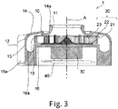
- Fig. 3 is a longitudinal sectional view illustrating the blower 1 of the embodiment of the present invention.
- the blower 1 includes the impeller 20, a motor 30, and a duct 10.
- the impeller 20 is accommodated in an internal space of the duct 10.
- the motor 30 is located below the impeller 20, and rotates the impeller 20 about the central axis A.
- the impeller 20 is connected to a shaft (not illustrated) extending in an axial direction from the motor 30, and supported so as to be rotatable about the central axis A. That is, the impeller 20 is rotatable about the central axis A extending in the vertical direction.
- a control board 40 is disposed on a lower side of the motor 30 in the axial direction, and controls the motor 30.
- the duct 10 includes an airflow passage 13 in the inner space thereof, a suction port 11 through which a fluid flows in the inner space, and an air outlet 12 through which the fluid is discharged from the inner space.
- the impeller 20 is accommodated in the duct 10.
- the duct 10 is constructed with a cover 14, a circumferential wall 15, and a motor housing 16, and the airflow passage 13 is formed in the internal space surrounded by these components. More particularly, the duct 10 includes the cover 14 covering at least a part of a blade 23 and an upper portion of a shroud 22.
- the cover 14 covers the upper portion of the impeller 20, and is formed into an annular shape as seen in axial plan view. An outer diameter of the cover 14 is larger than an outer diameter of the impeller 20.
- the duct 10 is constructed with a member including the cover 14 and a part of the circumferential wall 15 and a member including a part of the circumferential wall 15 and the motor housing 16. Consequently, the duct 10 can be constructed at low cost because the two members can be molded as separate resin members.
- a cylindrical portion 14a extending upward in the axial direction is provided at the central portion of the cover 14.
- the circular suction port 11 is formed in the cylindrical portion 14a as seen in axial plan view.
- the suction port 11 is disposed opposite an opening 22a of the shroud 22 (to be described later) in the axial direction, and gas (fluid) flows into the internal space of the duct 10 from the outside through the suction port 11.
- the circumferential wall 15 covers the impeller 20 from the lateral side, extends downward in the axial direction from an outer circumference of the cover 14, and is formed into a cylindrical shape.
- a nozzle 15a extending to the radial outside is provided in the circumferential wall 15, and the air outlet 12 through which the gas (fluid) is discharged from the internal space of the duct 10 is formed in the nozzle 15a.
- the motor housing 16 is located on a lower side in the axial direction of the impeller 20. More particularly, the blower 1 further includes the motor housing 16 located below a base plate 21 (to be described later). A top surface of the motor housing 16 spreads radially, extends to the lower end of the circumferential wall 15, and is connected to the circumferential wall 15. In addition, the circumferential surface of the motor housing 16 is formed in a cylindrical shape extending axially downward from the outer circumference of the circumferential wall 15, and the motor 30 and the control board 40 are accommodated in the motor housing 16.
- An annular recess 16a recessed downward on the radial outside of the impeller 20 is formed on the top surface of the motor housing 16.
- the airflow passage 13 including an annular region on the radial outside of the impeller 20 is formed between the suction port 11 and the air outlet 12 by the circumferential wall 15, the recess 16a, and the cover 14.
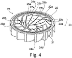
- Fig. 4 is a perspective view illustrating the impeller 20 of the embodiment of the present invention when the impeller 20 is viewed from above
- Fig. 5 is a plan view illustrating the impeller 20 of the embodiment of the present invention
- Fig. 6 is a side sectional view illustrating the impeller 20 of the embodiment of the present invention.
- the impeller 20 includes a plurality of blades 23, the annular shroud 22, and the base plate 21.
- the blade 23 is interposed between the base plate 21 and the shroud 22.
- the plurality of blades 23 are circumferentially arranged.
- the shroud 22 has an annular shape connecting the upper portions of the plurality of blades 23, and has the opening 22a located opposite the suction port 11 in the axial direction. More particularly, the shroud 22 is formed into the annular shape by connecting upper portions of the plurality of blades 23, and the opening 22a for taking the gas is formed in a central portion of the shroud 22.
- the opening 22a has a circular shape as seen in axial plan view.
- the base plate 21 connects the lower portions of the plurality of blades 23, and spreads in the radial direction.
- the base plate 21 is formed into a disc shape.
- the base plate 21 has a base plate protrusion 21a protruding downward from the bottom surface of the base plate 21. More particularly, the base plate protrusion 21a protrudes from the radial outer edge of the bottom surface of the base plate 21, and is formed into the annular shape (see Fig. 6 ).
- the blade 23 includes a first blade 23a and a second blade 23b, which have different radial lengths, and the first blades 23a and the second blades 23b are alternately arranged in the circumferential direction.
- the first blade 23a and the second blade 23b are a plate-shaped member, which rises in the axial direction and extends from the radial inside to the outside.
- the radially inner end of the first blade 23a is located on the radial inside of the radially inner end of the second blade 23b, and the first blade 23a is longer than the second blade 23b in the radial direction.
- the first blade 23a and the second blade 23b are curved such that the radially outer end is inclined on a rear side in the rotational direction with respect to the radial inner end, and such that the rear side in the rotation direction is recessed (see Fig. 5 ).
- a distance between the first blade 23a and the second blade 23b increases toward the radial outside.
- the radially outer ends 24a, 24b of the first blade 23a and the second blade 23b extend to the radial outside of the outer circumference of the base plate 21 (see Fig. 4 ). That is, the radially outer ends 24a, 24b of the blade 23 extend to the radial outside of the outer circumference of the base plate 21.
- the radially inner ends of the first blade 23a and the second blade 23b extend to the radial inside of the suction port 11 (see Fig. 3 ). That is, the radially inner end of the blade 23 extends to the radial inside of the suction port 11. Consequently, the blade 23 can be formed large in the radial direction, and an amount of air generated by the rotation of the impeller 20 can be increased.
- the outer circumference of the base plate 21 may have another shape, for example, a part of a member from a circumferential outer edge may be notched radially inward.
- the upper ends of the first blade 23a and the second blade 23b have protrusions 25a, 25b that protrude upward in the axial direction (see Fig. 6 ).
- the protrusions 25a, 25b are located on the radial inside of the opening 22a while aligned on an identical circle, and protrude upward from the upper end of the shroud 22.
- first blade 23a and the second blade 23b include inclined surfaces 26a, 26b extending downward from the protrusions 25a, 25b toward the radial inside and inclined surfaces 27a, 27b extending downward from the protrusions 25a, 25b toward the radial outside, respectively.
- protrusions 28a, 28b protruding axially upward are formed on the radial outside of the opening 22a of the shroud 22, and the upper ends of the protrusions 28a, 28b extend to the bottom surface of the shroud 22 and is connected to the shroud 22. That is, the blade 23 includes the protrusions 28a, 28b protruding axially upward on the radial outside of a first projection 17 (see Fig. 7 ) (to be described later). Consequently, the blade 23 can axially be formed larger on the radial outside of the opening 22a, and the amount of air generated by the rotation of the impeller 20 can be increased.
- the base plate 21, the shroud 22, and the blade 23 are formed by an identical resin molding product made of an identical material, and an inner diameter D2 of the shroud 22 is formed equal to an outer diameter D1 of the base plate 21 (see Fig. 6 ).
- the impeller 20 can integrally be molded using the die, and mass productivity of the impeller 20 can be improved. Note that, even in the case that the inner diameter D2 of the shroud 22 is formed larger than the outer diameter D1 of the base plate 21, the impeller 20 can integrally be molded using the die.
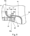
- Figs. 7 and 8 are enlarged longitudinal sectional views illustrating a part of the blower 1 of the embodiment of the present invention, and illustrate a relationship between the duct 10 and the impeller 20.
- the shroud 22 includes an inner circumferential surface 22b constituting the opening 22a.
- the cover 14 includes the first projection 17, which projects axially downward from the bottom surface of the cover 14 and is disposed on the radial inside of the inner circumferential surface 22b of the shroud 22.
- the outer circumferential surface of the first projection 17 is radially opposed to the inner circumferential surface 22b of the shroud 22.
- the outer circumferential surface of the first projection 17 and the inner circumferential surface 22b of the shroud 22 are not necessarily opposed to each other on the circumferential surface. That is, the outer surface of the first projection 17 may radially be opposed to the inner surface 22b of the shroud 22.
- the shapes of the outer surface of the first projection 17 and the inner surface 22b of the shroud 22 are not limited to the circumferential surface. For example, in the outer surface of the first projection 17 and the inner surface 22b of the shroud 22, irregularities may be formed on a part of the circumferential surface.
- the first projection 17 blocks the flow path of the air R1 that flows backward onto the radial inside from the gap between the shroud 22 and the cover 14. Consequently, a part of the air blown out onto the radial outside of the impeller 20 can be prevented from flowing backward from the gap between the shroud 22 and the cover 14. Thus, the degradation of the blowing efficiency can be prevented by the generation of the turbulence or the air resistance of the flowing-back air in the airflow passage 13.
- the radial gap between the outer circumferential surface of the first projection 17 and the inner circumferential surface 22b of the shroud 22 is narrower than the axial gap between the shroud 22 and the cover 14. Thus, a flow of air R1 flowing backward to the radial inside from the gap between the shroud 22 and the cover 14 can be blocked.
- the lower end of the radially outer end of the first projection 17 extends to the position where the height in the axial direction is substantially equal to or lower than the height at the lower end of the inner circumferential surface 22b of the shroud 22. Consequently, the air circulating toward the radial outside along the bottom surface of the cover 14 is smoothly guided from the lower end of the first projection 17 to the lower end of the inner circumferential surface 22b of the shroud 22, and blown out to the radial outside of the impeller 20 through the bottom surface of the shroud 22.
- This enables the further improvement of the blowing efficiency of the blower 1. In other words, a strike of the circulating air on the inner circumferential surface 22b of the shroud 22 is reduced, so that the air can efficiently be blown out onto the radial outside.
- the protrusions 28a, 28b (not illustrated in Fig. 7 , see Fig. 4 ) of the first blade 23a and the second blade 23b are connected to the bottom surface of the shroud 22 on the radial outside with respect to the first projection 17, and the first projection 17 is vertically opposed to the inclined surfaces 27a, 27b.
- a region of the first blade 23a and the second blade 23b located on the radial outside of the first projection 17 is a blade first region L1
- a region vertically opposed to the first projection 17 is a blade second region L2
- the upper end of the blade first region L1 is located above the upper end at the radially outer end of the blade second region L2 in the upper ends of the first blade 23a and the second blade 23b.
- the blade 23 includes the blade first region L1 located on the radial outside of the first projection 17 and the blade second region L2 vertically opposed to the first projection 17, and the upper end of the blade first region L1 is located above the upper end at the radially outer end of the blade second region L2.
- annular groove 16b which is axially opposed to the base plate protrusion 21a protruding from the outer circumference of the bottom surface of the base plate 21, is provided on the top surface of the motor housing 16.
- a radial width of the groove 16b is larger than that of the base plate protrusion 21a.
- the axial gap between the lower end of the base plate protrusion 21a and the top surface of the motor housing 16 is narrower than the axial gap between the bottom surface of the base plate 21 and the top surface of the motor housing 16.
- the base plate protrusion 21a may be formed at a position other than the radially outer edge of the base plate 21.
- the base plate protrusion 21a may be formed at a position inside the radially outer edge. Even in this case, a part of the air blown out onto the radial outside of the impeller 20 can be prevented from flowing in the gap between the bottom surface of the base plate 21 and the top surface of the motor housing 16 as air R2 to flow backward onto the radial inside.
- the impeller 20 rotates about the central axis A. Consequently, the air is taken in the duct 10 through the suction port 11.
- the air taken in the duct 10 is accelerated toward the radial outside by the impeller 20.
- the air accelerated toward the radial outside passes between the shroud 22 and the base plate 21, and is blown out to the radial outside of the impeller 20.
- the air blown out to the radial outside of the impeller 20 is discharged from the air outlet 12 to the outside of the duct 10 through the airflow passage 13 formed in the circumferential direction in the duct 10.
- Fig. 9 is an enlarged longitudinal sectional view illustrating a part of a blower 1 according to a modification of the exemplary embodiment of the present invention.
- the second projection 18 projecting downward in the axial direction may be provided on the bottom surface of the cover 14.
- the inner circumferential surface of the second projection 18 is radially opposed to the outer circumferential surface of the shroud 22.
- the second projection 18 blocks the airflow flowing in a gap between the shroud 22 and the cover 14. Consequently, a part of the air blown out onto the radial outside of the impeller 20 can be prevented from flowing in the gap between the shroud 22 and the cover 14, and the generation of the turbulence or the backward flow in the airflow passage 13 can be prevented. Note that, although both of the first projection 17 and the second projection 18 may be provided, the degradation of the blowing efficiency due to the generation of the turbulence or the air resistance of flowing-back air in the airflow passage 13 can be prevented even if only one of the first projection 17 and the second projection 18 is provided.
- the radial gap between the inner circumferential surface of the second projection 18 and the outer circumferential surface of the shroud 22 is narrower than the axial gap between the shroud 22 and the cover 14.
- Fig. 10 is an enlarged longitudinal sectional view illustrating a vicinity of the shroud 22 in the blower 1 of the modification of the exemplary embodiment of the present invention.
- the inner circumferential surface 22b of the shroud 22 includes a first inner circumferential surface 221 and a second inner circumferential surface 222, and the first inner circumferential surface 221 is disposed axially above the second inner circumferential surface 222.
- the first inner circumferential surface 221 is formed in parallel to the axial direction, and the second inner circumferential surface 222 is inclined with respect to the axial direction so as to be away from the central axis A toward the lower side in axial direction, and projectively curved toward the radial inside.
- first inner circumferential surface 221 and the second inner circumferential surface 222 are connected to each other while a curved portion 223 projectively curved toward the radial inside is interposed therebetween. That is, the lower end of the first inner circumferential surface 221 and the upper end of the second inner circumferential surface 222 are smoothly connected to each other.
- the radial gap between the outer circumferential surface of the first projection 17 and the inner circumferential surface 22b of the shroud 22 is formed wider in the axial lower side than the axial upper side.
- the first inner circumferential surface 221 and the second inner circumferential surface 222 are connected to each other while the curved portion 223 projectively curved toward the radial inside is interposed therebetween, and the second inner circumferential surface 222 is projectively curved toward the radial inside, which allows the air circulating along the inner circumferential surface 22b of the shroud 22 to be smoothly guided onto the radial outside. Consequently, the reduction in the blowing efficiency of the blower 1 can further be prevented.
- the expression "connected to each other with the curved portion 223 interposed therebetween” means that the lower end of the first inner circumferential surface 221 and the upper end of the second inner circumferential surface 222 are smoothly connected to each other.
- a vertical thickness of the shroud 22 is secured by a predetermined width from the upper end of the inner circumferential surface 22b, so that the reduction in rigidity of the shroud 22 can be prevented.
- Fig. 11 is an enlarged longitudinal sectional view illustrating the vicinity of the shroud 22 of the blower 1 according to the modification of the exemplary embodiment of the present invention.
- the plane parallel to the axial direction may be omitted in the inner circumferential surface 22b of the shroud 22.
- the entire inner circumferential surface 22b is constructed with the second inner circumferential surface 222.
- the second inner circumferential surface 222 is projectively curved toward the radial inside.
- the second inner circumferential surface 222 may be formed by a conical surface that is not curved but inclined with respect to the axial direction so as to be away from the central axis A toward the lower side in axial direction.
- the inner diameter of the shroud 22 is formed equal to or larger than the outer diameter of the base plate 21, so that the upper and lower dies can be pulled out onto the upper side and the lower side in the axial direction, respectively, while the mutual interference between the upper and lower dies is prevented.
- the impeller 20 can integrally be molded using the die, and the mass productivity of the impeller 20 can be improved.
- the first projection 17 projects axially downward from the bottom surface of the cover 14, and the first projection 17 is disposed on the radial inside of the inner circumferential surface of the shroud 22. This enables the first projection 17 to block the passage of the air flowing backward onto the radial inside due to the air flowing in the gap between the shroud 22 and the cover 14. Consequently, a part of the air blown out to the radial outside of the impeller 20 is prevented from flowing in the gap between the shroud 22 and the cover 14, and the degradation of the blowing efficiency due to the generation of the turbulence or the air resistance of the flowing-back air in the airflow passage 13 can be prevented.
- the outer circumferential surface of the first projection 17 is radially opposed to the inner circumferential surface of the shroud 22. Consequently, the radial inside of the gap between the shroud 22 and the cover 14 is closed by the first projection 17, and the degradation of the blowing efficiency due to the generation of the turbulence or the air resistance of the flowing-back air in the airflow passage 13 can be prevented.
- the radial gap between the outer circumferential surface of the first projection 17 and the inner circumferential surface of the shroud 22 is kept constant in the axial direction.
- the radial gap between the outer circumferential surface of the first projection 17 and the inner circumferential surface of the shroud 22 may not be kept constant in the axial direction.
- at least one of the outer circumferential surface of the first projection 17 and the inner circumferential surface of the shroud 22 may be curved.
- the upper end of the blade first region is located above the upper end at the radially outer end of the blade second region in the upper end of the blade 23.
- the lower end of the inner circumferential surface 22b of the shroud 22 and the lower end of the radially outer end of the first projection 17 have the substantially identical height in the axial direction. Consequently, the air circulating toward the radial outside along the bottom surface of the cover 14 is smoothly guided from the lower end of the first projection 17 to the lower end of the inner circumferential surface 22b of the shroud 22, and blown out to the radial outside of the impeller 20 through the bottom surface of the shroud 22.
- the blowing efficiency can further be improved by reducing the air resistance of the first projection 17.
- the lower end of the inner circumferential surface 22b of the shroud 22 may axially be located above the lower end of the radially outer end of the first projection 17. Even in this case, the air circulating toward the radial outside along the bottom surface of the cover 14 is smoothly guided from the lower end of the first projection 17 to the lower end of the inner circumferential surface 22b of the shroud 22, so that the blowing efficiency of the blower 1 can be improved.
- the radial gap between the inner circumferential surface 22b of the shroud 22 and the radially outer end of the first projection 17 is also narrowed, so that a part of the air blown out onto the radial outside of the impeller 20 can be prevented from flowing backward from the gap between the shroud 22 and the cover 14.
- the radially outer end of the blade 23 extends to the radial outside of the outer circumference of the base plate 21, and the radially inner end of the blade 23 extends to the radial inside of the suction port 11, so that the blade 23 can radially be formed larger to increase the amount of air generated by the rotation of the impeller 20.
- the axial gap between the lower end of the base plate protrusion 21a and the top surface of the motor housing 16 is narrower than the axial gap between the bottom surface of the base plate 21 and the top surface of the motor housing 16, so that the base plate protrusion 21a blocks the airflow flowing in the axial gap between the bottom surface of the base plate 21 and the top surface of the motor housing 16. Consequently, a part of the air blown out onto the radial outside of the impeller 20 can be prevented from flowing in the gap between the bottom surface of the base plate 21 and the top surface of the motor housing 16, and the degradation of the blowing efficiency due to the generation of the turbulence or the air resistance of the flowing-back air in the airflow passage 13 can be prevented.
- the base plate protrusion 21a is located on the radially outer edge of the base plate 21.
- the groove 16b vertically opposed to the base plate protrusion 21a is provided on the top surface of the motor housing 16.
- the groove 16b is larger than the base plate protrusion 21a in the radial width. That is, the groove 16b is formed on the top surface of the motor housing 16.
- the groove 16b is vertically opposed to the base plate protrusion 21a and has the radial width larger than a radial width of the base plate protrusion 21a.
- the base plate protrusion 21a is disposed close to the groove 16b, so that the axial gap between the bottom surface of the base plate 21 and the top surface of the motor housing 16 can further be narrowed. Therefore, the part of the air flowing in the gap between the bottom surface of the base plate 21 and the top surface of the motor housing 16 can further be prevented.
- the blower 1 of the present invention is mounted on the cleaning robot 100 as illustrated in Fig. 1 .
- the blower 1 may be mounted on not only the cleaning robot 100 but also vacuum cleaners such as a handy cleaner. Consequently, the vacuum cleaner having the high blowing efficiency can be constructed.
- the blower 1 may also be mounted on an apparatus other than the vacuum cleaner.
- the blower 1 of the present invention may be mounted on an electronic device such as a personal computer for the purpose of internal cooling.
- the blower 1 of the present invention may also be mounted on various other office automation instruments, medical instruments, household electrical appliances, or transport instruments.
- blower 1 may be different from the above embodiment and modifications. Furthermore, each element appearing in the embodiment and the modifications may appropriately be combined within a range in which inconsistency is not generated.
- the blower of the present invention having the high blowing efficiency is suitable for the vacuum cleaner.
- the blower of the present invention can also be used for other electronic devices.
Landscapes
- Engineering & Computer Science (AREA)
- Mechanical Engineering (AREA)
- General Engineering & Computer Science (AREA)
- Structures Of Non-Positive Displacement Pumps (AREA)
- Electric Suction Cleaners (AREA)
Abstract
Description
- The present invention relates to a blower and a vacuum cleaner.
- For example, Japanese Laid-Open Patent Publication No.
2002-156128 2002-156128 - The casing includes an intake-side end, a straight portion, and an inclined step. An inner diameter of an intake-side end is equal to or larger than an outer diameter of the base plate.
- Air is discharged from a turbofan center portion to an outer circumferential direction. It is claimed that a noise of the turbofan is reduced because the shroud has the above characteristics.
- Patent Literature 1: Japanese Laid-Open Patent Publication No.
2002-156128 - However, in the turbofan disclosed in Japanese Laid-Open Patent Publication No.
2002-156128 - An object of the present invention is to provide a blower capable of preventing the generation of the turbulence in the airflow passage of a duct, and improving blowing efficiency by preventing the airflow from flowing backward to the radial inside. In addition, another object of the present invention is to provide a vacuum cleaner including the blower capable of improving the blowing efficiency.
- According to an exemplary embodiment of the present invention, a blower includes: an impeller rotatable about a central axis extending in a vertical direction; a motor that is positioned on a lower side of the impeller and rotates the impeller about the central axis; and a duct including an airflow passage in an inner space, a suction port through which a fluid flows in the inner space, and an air outlet through which the fluid is discharged from the inner space, the impeller being accommodated in the duct. The impeller includes: a plurality of blades arranged in a circumferential direction; a shroud that has an annular shape, connects upper portions of the plurality of blades, and includes an opening located opposite the suction port in an axial direction; and a base plate that connects lower portions of the plurality of blades and extends in a radial direction, the duct includes a cover covering at least a part of the blade and an upper portion of the shroud, an inner diameter of the shroud is equal to or larger than an outer diameter of the base plate, and the cover includes a first projection that projects axially downward from a bottom surface of the cover and is disposed on a radial inside of an inner circumferential surface of the shroud.
- An exemplary embodiment of the present invention can provide the blower capable of improving the blowing efficiency. Additionally, an exemplary embodiment of the present invention can provide the vacuum cleaner including the blower.
-
-
Fig. 1 is a sectional view illustrating a cleaning robot according to an embodiment of the present invention. -
Fig. 2 is a perspective view illustrating a blower of the embodiment of the present invention. -
Fig. 3 is a longitudinal sectional view illustrating the blower of the embodiment of the present invention. -
Fig. 4 is a perspective view illustrating an impeller of the embodiment of the present invention when the impeller is viewed from above. -
Fig. 5 is a plan view illustrating the impeller of the embodiment of the present invention. -
Fig. 6 is a side sectional view illustrating the impeller of the embodiment of the present invention. -
Fig. 7 is an enlarged longitudinal sectional view illustrating a part of the blower of the embodiment of the present invention. -
Fig. 8 is an enlarged longitudinal sectional view illustrating a part of the blower of the embodiment of the present invention. -
Fig. 9 is an enlarged longitudinal sectional view illustrating a part of a blower according to a modification of the embodiment of the present invention. -
Fig. 10 is an enlarged longitudinal sectional view illustrating a vicinity of a shroud in the blower of the modification of the embodiment of the present invention. -
Fig. 11 is an enlarged longitudinal sectional view illustrating the vicinity of the shroud in the blower of the modification of the embodiment of the present invention. - Hereinafter, an exemplary embodiment of the present invention will be described with reference to the drawings. Note that, in the following description, an extending direction of a central axis A of a
blower 1 inFig. 3 is simply referred to as an "axial direction", and a radial direction and a circumferential direction about the central axis A of theblower 1 are simply referred to as a "radial direction" and a "circumferential direction". Similarly, with respect to animpeller 20 inFigs. 4 to 6 , directions matched with the axial direction, the radial direction, and the circumferential direction of theblower 1 in a state where theimpeller 20 is incorporated in theblower 1 are simply referred to as the "axial direction", the "radial direction", and the "circumferential direction". Note that, a vertical direction is simply used for the description, but does not limit an actual positional relationship and a direction. - A blower according to an exemplary embodiment of the present invention will be described.
Fig. 1 is a sectional view of acleaning robot 100 according to an exemplary embodiment of the present invention. As illustrated inFig. 1 , theblower 1 is mounted on the cleaning robot (vacuum cleaner) 100 to serve as suction means. - The
cleaning robot 100 sucks air containing dust on a floor surface F while self-propelling the floor surface F at an installed place, and exhausts the air from which the dust is removed, thereby cleaning the floor surface F. Thecleaning robot 100 includes a disc-shaped chassis 101 and includes, in the disc-shaped chassis 101, asuction passage 104, adust container 105, afilter 106, anexhaust passage 107, and theblower 1. Adriving wheel 109 and afront wheels 110 are provided on a bottom surface of thechassis 101. - The
chassis 101 includes aninlet port 103 in a center of the bottom surface and anexhaust port 108 at the side surface. By driving theblower 1, thecleaning robot 100 sucks the air including the dust on the floor surface F from theinlet port 103 while self-propelling. The air containing the dust sucked into thechassis 101 from theinlet port 103 passes through thesuction passage 104, and flows into thedust container 105. The airflow flowing in thedust container 105 passes through thefilter 106, and is sucked in theblower 1 through theexhaust passage 107. The air sucked by theblower 1 is exhausted diagonally upward rearward from theexhaust port 108. At this point, the dust contained in the airflow in thedust container 105 is caught by thefilter 106, and dust D is accumulated in thedust container 105. -
Fig. 2 is a perspective view illustrating theblower 1 of the embodiment of the present invention. In addition,Fig. 3 is a longitudinal sectional view illustrating theblower 1 of the embodiment of the present invention. As illustrated inFigs. 2 and3 , theblower 1 includes theimpeller 20, amotor 30, and aduct 10. Theimpeller 20 is accommodated in an internal space of theduct 10. Themotor 30 is located below theimpeller 20, and rotates theimpeller 20 about the central axis A. - The
impeller 20 is connected to a shaft (not illustrated) extending in an axial direction from themotor 30, and supported so as to be rotatable about the central axis A. That is, theimpeller 20 is rotatable about the central axis A extending in the vertical direction. Acontrol board 40 is disposed on a lower side of themotor 30 in the axial direction, and controls themotor 30. - The
duct 10 includes anairflow passage 13 in the inner space thereof, asuction port 11 through which a fluid flows in the inner space, and anair outlet 12 through which the fluid is discharged from the inner space. Theimpeller 20 is accommodated in theduct 10. Theduct 10 is constructed with acover 14, acircumferential wall 15, and amotor housing 16, and theairflow passage 13 is formed in the internal space surrounded by these components. More particularly, theduct 10 includes thecover 14 covering at least a part of ablade 23 and an upper portion of ashroud 22. Thecover 14 covers the upper portion of theimpeller 20, and is formed into an annular shape as seen in axial plan view. An outer diameter of thecover 14 is larger than an outer diameter of theimpeller 20. Note that, in the embodiment, theduct 10 is constructed with a member including thecover 14 and a part of thecircumferential wall 15 and a member including a part of thecircumferential wall 15 and themotor housing 16. Consequently, theduct 10 can be constructed at low cost because the two members can be molded as separate resin members. - A
cylindrical portion 14a extending upward in the axial direction is provided at the central portion of thecover 14. Thecircular suction port 11 is formed in thecylindrical portion 14a as seen in axial plan view. Thesuction port 11 is disposed opposite anopening 22a of the shroud 22 (to be described later) in the axial direction, and gas (fluid) flows into the internal space of theduct 10 from the outside through thesuction port 11. - The
circumferential wall 15 covers theimpeller 20 from the lateral side, extends downward in the axial direction from an outer circumference of thecover 14, and is formed into a cylindrical shape. In addition, anozzle 15a extending to the radial outside is provided in thecircumferential wall 15, and theair outlet 12 through which the gas (fluid) is discharged from the internal space of theduct 10 is formed in thenozzle 15a. - The
motor housing 16 is located on a lower side in the axial direction of theimpeller 20. More particularly, theblower 1 further includes themotor housing 16 located below a base plate 21 (to be described later). A top surface of themotor housing 16 spreads radially, extends to the lower end of thecircumferential wall 15, and is connected to thecircumferential wall 15. In addition, the circumferential surface of themotor housing 16 is formed in a cylindrical shape extending axially downward from the outer circumference of thecircumferential wall 15, and themotor 30 and thecontrol board 40 are accommodated in themotor housing 16. - An
annular recess 16a recessed downward on the radial outside of theimpeller 20 is formed on the top surface of themotor housing 16. Theairflow passage 13 including an annular region on the radial outside of theimpeller 20 is formed between thesuction port 11 and theair outlet 12 by thecircumferential wall 15, therecess 16a, and thecover 14. -
Fig. 4 is a perspective view illustrating theimpeller 20 of the embodiment of the present invention when theimpeller 20 is viewed from above, andFig. 5 is a plan view illustrating theimpeller 20 of the embodiment of the present invention. In addition,Fig. 6 is a side sectional view illustrating theimpeller 20 of the embodiment of the present invention. - As illustrated in
Figs. 4 to 6 , theimpeller 20 includes a plurality ofblades 23, theannular shroud 22, and thebase plate 21. Theblade 23 is interposed between thebase plate 21 and theshroud 22. The plurality ofblades 23 are circumferentially arranged. - The
shroud 22 has an annular shape connecting the upper portions of the plurality ofblades 23, and has theopening 22a located opposite thesuction port 11 in the axial direction. More particularly, theshroud 22 is formed into the annular shape by connecting upper portions of the plurality ofblades 23, and theopening 22a for taking the gas is formed in a central portion of theshroud 22. Theopening 22a has a circular shape as seen in axial plan view. - The
base plate 21 connects the lower portions of the plurality ofblades 23, and spreads in the radial direction. Thebase plate 21 is formed into a disc shape. Thebase plate 21 has abase plate protrusion 21a protruding downward from the bottom surface of thebase plate 21. More particularly, thebase plate protrusion 21a protrudes from the radial outer edge of the bottom surface of thebase plate 21, and is formed into the annular shape (seeFig. 6 ). - The
blade 23 includes afirst blade 23a and asecond blade 23b, which have different radial lengths, and thefirst blades 23a and thesecond blades 23b are alternately arranged in the circumferential direction. Thefirst blade 23a and thesecond blade 23b are a plate-shaped member, which rises in the axial direction and extends from the radial inside to the outside. The radially inner end of thefirst blade 23a is located on the radial inside of the radially inner end of thesecond blade 23b, and thefirst blade 23a is longer than thesecond blade 23b in the radial direction. - In addition, in the case that the
impeller 20 is rotated counterclockwise as seen in axial plan view from above, thefirst blade 23a and thesecond blade 23b are curved such that the radially outer end is inclined on a rear side in the rotational direction with respect to the radial inner end, and such that the rear side in the rotation direction is recessed (seeFig. 5 ). In addition, a distance between thefirst blade 23a and thesecond blade 23b increases toward the radial outside. - In addition, the radially outer ends 24a, 24b of the
first blade 23a and thesecond blade 23b extend to the radial outside of the outer circumference of the base plate 21 (seeFig. 4 ). That is, the radially outer ends 24a, 24b of theblade 23 extend to the radial outside of the outer circumference of thebase plate 21. In addition, the radially inner ends of thefirst blade 23a and thesecond blade 23b extend to the radial inside of the suction port 11 (seeFig. 3 ). That is, the radially inner end of theblade 23 extends to the radial inside of thesuction port 11. Consequently, theblade 23 can be formed large in the radial direction, and an amount of air generated by the rotation of theimpeller 20 can be increased. The outer circumference of thebase plate 21 may have another shape, for example, a part of a member from a circumferential outer edge may be notched radially inward. - The upper ends of the
first blade 23a and thesecond blade 23b haveprotrusions Fig. 6 ). Theprotrusions opening 22a while aligned on an identical circle, and protrude upward from the upper end of theshroud 22. - In addition, the upper ends of the
first blade 23a and thesecond blade 23b includeinclined surfaces protrusions inclined surfaces protrusions - In addition, in the
inclined surfaces protrusions opening 22a of theshroud 22, and the upper ends of theprotrusions shroud 22 and is connected to theshroud 22. That is, theblade 23 includes theprotrusions Fig. 7 ) (to be described later). Consequently, theblade 23 can axially be formed larger on the radial outside of theopening 22a, and the amount of air generated by the rotation of theimpeller 20 can be increased. - The
base plate 21, theshroud 22, and theblade 23 are formed by an identical resin molding product made of an identical material, and an inner diameter D2 of theshroud 22 is formed equal to an outer diameter D1 of the base plate 21 (seeFig. 6 ). - Consequently, in forming the
impeller 20 straddling thebase plate 21 and theshroud 22, upper and lower dies can be pulled out onto the upper side and the lower side in the axial direction, respectively, while mutual interference between the upper and lower dies is prevented. Thus, theimpeller 20 can integrally be molded using the die, and mass productivity of theimpeller 20 can be improved. Note that, even in the case that the inner diameter D2 of theshroud 22 is formed larger than the outer diameter D1 of thebase plate 21, theimpeller 20 can integrally be molded using the die. -
Figs. 7 and8 are enlarged longitudinal sectional views illustrating a part of theblower 1 of the embodiment of the present invention, and illustrate a relationship between theduct 10 and theimpeller 20. In addition, as illustrated inFig. 7 , theshroud 22 includes an innercircumferential surface 22b constituting theopening 22a. Thecover 14 includes thefirst projection 17, which projects axially downward from the bottom surface of thecover 14 and is disposed on the radial inside of the innercircumferential surface 22b of theshroud 22. The outer circumferential surface of thefirst projection 17 is radially opposed to the innercircumferential surface 22b of theshroud 22. Note that, the outer circumferential surface of thefirst projection 17 and the innercircumferential surface 22b of theshroud 22 are not necessarily opposed to each other on the circumferential surface. That is, the outer surface of thefirst projection 17 may radially be opposed to theinner surface 22b of theshroud 22. Note that, the shapes of the outer surface of thefirst projection 17 and theinner surface 22b of theshroud 22 are not limited to the circumferential surface. For example, in the outer surface of thefirst projection 17 and theinner surface 22b of theshroud 22, irregularities may be formed on a part of the circumferential surface. - The
first projection 17 blocks the flow path of the air R1 that flows backward onto the radial inside from the gap between theshroud 22 and thecover 14. Consequently, a part of the air blown out onto the radial outside of theimpeller 20 can be prevented from flowing backward from the gap between theshroud 22 and thecover 14. Thus, the degradation of the blowing efficiency can be prevented by the generation of the turbulence or the air resistance of the flowing-back air in theairflow passage 13. In addition, the radial gap between the outer circumferential surface of thefirst projection 17 and the innercircumferential surface 22b of theshroud 22 is narrower than the axial gap between theshroud 22 and thecover 14. Thus, a flow of air R1 flowing backward to the radial inside from the gap between theshroud 22 and thecover 14 can be blocked. - In addition, the lower end of the radially outer end of the
first projection 17 extends to the position where the height in the axial direction is substantially equal to or lower than the height at the lower end of the innercircumferential surface 22b of theshroud 22. Consequently, the air circulating toward the radial outside along the bottom surface of thecover 14 is smoothly guided from the lower end of thefirst projection 17 to the lower end of the innercircumferential surface 22b of theshroud 22, and blown out to the radial outside of theimpeller 20 through the bottom surface of theshroud 22. This enables the further improvement of the blowing efficiency of theblower 1. In other words, a strike of the circulating air on the innercircumferential surface 22b of theshroud 22 is reduced, so that the air can efficiently be blown out onto the radial outside. - Note that, as illustrated in
Fig. 8 , theprotrusions Fig. 7 , seeFig. 4 ) of thefirst blade 23a and thesecond blade 23b are connected to the bottom surface of theshroud 22 on the radial outside with respect to thefirst projection 17, and thefirst projection 17 is vertically opposed to theinclined surfaces first blade 23a and thesecond blade 23b located on the radial outside of thefirst projection 17 is a blade first region L1, and that a region vertically opposed to thefirst projection 17 is a blade second region L2, the upper end of the blade first region L1 is located above the upper end at the radially outer end of the blade second region L2 in the upper ends of thefirst blade 23a and thesecond blade 23b. - That is, the
blade 23 includes the blade first region L1 located on the radial outside of thefirst projection 17 and the blade second region L2 vertically opposed to thefirst projection 17, and the upper end of the blade first region L1 is located above the upper end at the radially outer end of the blade second region L2. Thus, even if theimpeller 20 vibrates vertically during the rotation, thefirst blade 23a and thesecond blade 23b can be prevented from contacting with thefirst projection 17. - In addition, referring to
Fig. 7 , anannular groove 16b, which is axially opposed to thebase plate protrusion 21a protruding from the outer circumference of the bottom surface of thebase plate 21, is provided on the top surface of themotor housing 16. A radial width of thegroove 16b is larger than that of thebase plate protrusion 21a. The axial gap between the bottom surface of thebase plate 21 and the top surface of themotor housing 16 can be narrowed by disposing thebase plate protrusion 21a close to thegroove 16b. - Consequently, a part of the air blown out onto the radial outside of the
impeller 20 can be prevented from flowing backward from the gap between the bottom surface of thebase plate 21 and the top surface of themotor housing 16, and the degradation of the blowing efficiency due to the generation of the turbulence or the air resistance of the flowing-back air in theairflow passage 13 can be prevented. - In addition, the axial gap between the lower end of the
base plate protrusion 21a and the top surface of themotor housing 16 is narrower than the axial gap between the bottom surface of thebase plate 21 and the top surface of themotor housing 16. Thus, a part of the air blown out onto the radial outside of theimpeller 20 can be prevented from flowing in the gap between the bottom surface of thebase plate 21 and the top surface of themotor housing 16 to flow backward onto the radial inside. - Note that, the
base plate protrusion 21a may be formed at a position other than the radially outer edge of thebase plate 21. For example, on the bottom surface of thebase plate 21, thebase plate protrusion 21a may be formed at a position inside the radially outer edge. Even in this case, a part of the air blown out onto the radial outside of theimpeller 20 can be prevented from flowing in the gap between the bottom surface of thebase plate 21 and the top surface of themotor housing 16 as air R2 to flow backward onto the radial inside. - When the
motor 30 is driven, theimpeller 20 rotates about the central axis A. Consequently, the air is taken in theduct 10 through thesuction port 11. The air taken in theduct 10 is accelerated toward the radial outside by theimpeller 20. The air accelerated toward the radial outside passes between theshroud 22 and thebase plate 21, and is blown out to the radial outside of theimpeller 20. The air blown out to the radial outside of theimpeller 20 is discharged from theair outlet 12 to the outside of theduct 10 through theairflow passage 13 formed in the circumferential direction in theduct 10. -
Fig. 9 is an enlarged longitudinal sectional view illustrating a part of ablower 1 according to a modification of the exemplary embodiment of the present invention. Thesecond projection 18 projecting downward in the axial direction may be provided on the bottom surface of thecover 14. The inner circumferential surface of thesecond projection 18 is radially opposed to the outer circumferential surface of theshroud 22. - The
second projection 18 blocks the airflow flowing in a gap between theshroud 22 and thecover 14. Consequently, a part of the air blown out onto the radial outside of theimpeller 20 can be prevented from flowing in the gap between theshroud 22 and thecover 14, and the generation of the turbulence or the backward flow in theairflow passage 13 can be prevented. Note that, although both of thefirst projection 17 and thesecond projection 18 may be provided, the degradation of the blowing efficiency due to the generation of the turbulence or the air resistance of flowing-back air in theairflow passage 13 can be prevented even if only one of thefirst projection 17 and thesecond projection 18 is provided. In addition, the radial gap between the inner circumferential surface of thesecond projection 18 and the outer circumferential surface of theshroud 22 is narrower than the axial gap between theshroud 22 and thecover 14. Thus, the flow of air flowing backward to the radial inside from the gap between theshroud 22 and thecover 14 can be blocked. -
Fig. 10 is an enlarged longitudinal sectional view illustrating a vicinity of theshroud 22 in theblower 1 of the modification of the exemplary embodiment of the present invention. The innercircumferential surface 22b of theshroud 22 includes a first inner circumferential surface 221 and a second innercircumferential surface 222, and the first inner circumferential surface 221 is disposed axially above the second innercircumferential surface 222. The first inner circumferential surface 221 is formed in parallel to the axial direction, and the second innercircumferential surface 222 is inclined with respect to the axial direction so as to be away from the central axis A toward the lower side in axial direction, and projectively curved toward the radial inside. In addition, the first inner circumferential surface 221 and the second innercircumferential surface 222 are connected to each other while acurved portion 223 projectively curved toward the radial inside is interposed therebetween. That is, the lower end of the first inner circumferential surface 221 and the upper end of the second innercircumferential surface 222 are smoothly connected to each other. - That is, the radial gap between the outer circumferential surface of the
first projection 17 and the innercircumferential surface 22b of theshroud 22 is formed wider in the axial lower side than the axial upper side. - Consequently, even if the
impeller 20 vibrates vertically during the rotation and even if the lower end of the innercircumferential surface 22b of theshroud 22 is axially lowered lower than the lower end of the radially outer end of thefirst projection 17, the air circulating toward the radial outside along the bottom surface of thecover 14 is smoothly guided from the lower end of thefirst projection 17 onto the radial outside along the second innercircumferential surface 222. Thus, reduction of the blowing efficiency of theblower 1 can be prevented even if theimpeller 20 vibrates vertically during the rotation. - The first inner circumferential surface 221 and the second inner
circumferential surface 222 are connected to each other while thecurved portion 223 projectively curved toward the radial inside is interposed therebetween, and the second innercircumferential surface 222 is projectively curved toward the radial inside, which allows the air circulating along the innercircumferential surface 22b of theshroud 22 to be smoothly guided onto the radial outside. Consequently, the reduction in the blowing efficiency of theblower 1 can further be prevented. As used herein, the expression "connected to each other with thecurved portion 223 interposed therebetween" means that the lower end of the first inner circumferential surface 221 and the upper end of the second innercircumferential surface 222 are smoothly connected to each other. - In addition, when the inner
circumferential surface 22b of theshroud 22 includes the first inner circumferential surface 221 formed in parallel to the axial direction, a vertical thickness of theshroud 22 is secured by a predetermined width from the upper end of the innercircumferential surface 22b, so that the reduction in rigidity of theshroud 22 can be prevented. - Note that,
Fig. 11 is an enlarged longitudinal sectional view illustrating the vicinity of theshroud 22 of theblower 1 according to the modification of the exemplary embodiment of the present invention. As illustrated inFig. 11 , the plane parallel to the axial direction may be omitted in the innercircumferential surface 22b of theshroud 22. In this case, the entire innercircumferential surface 22b is constructed with the second innercircumferential surface 222. With this configuration, even if theimpeller 20 vibrates vertically during the rotation, the reduction of the blowing efficiency of theblower 1 can further be prevented. - Note that, in
Figs. 10 and11 , the second innercircumferential surface 222 is projectively curved toward the radial inside. Alternatively, the second innercircumferential surface 222 may be formed by a conical surface that is not curved but inclined with respect to the axial direction so as to be away from the central axis A toward the lower side in axial direction. - According to the embodiment, the inner diameter of the
shroud 22 is formed equal to or larger than the outer diameter of thebase plate 21, so that the upper and lower dies can be pulled out onto the upper side and the lower side in the axial direction, respectively, while the mutual interference between the upper and lower dies is prevented. Thus, theimpeller 20 can integrally be molded using the die, and the mass productivity of theimpeller 20 can be improved. - In addition, the
first projection 17 projects axially downward from the bottom surface of thecover 14, and thefirst projection 17 is disposed on the radial inside of the inner circumferential surface of theshroud 22. This enables thefirst projection 17 to block the passage of the air flowing backward onto the radial inside due to the air flowing in the gap between theshroud 22 and thecover 14. Consequently, a part of the air blown out to the radial outside of theimpeller 20 is prevented from flowing in the gap between theshroud 22 and thecover 14, and the degradation of the blowing efficiency due to the generation of the turbulence or the air resistance of the flowing-back air in theairflow passage 13 can be prevented. - In addition, the outer circumferential surface of the
first projection 17 is radially opposed to the inner circumferential surface of theshroud 22. Consequently, the radial inside of the gap between theshroud 22 and thecover 14 is closed by thefirst projection 17, and the degradation of the blowing efficiency due to the generation of the turbulence or the air resistance of the flowing-back air in theairflow passage 13 can be prevented. Note that, in the embodiment, the radial gap between the outer circumferential surface of thefirst projection 17 and the inner circumferential surface of theshroud 22 is kept constant in the axial direction. However, the radial gap between the outer circumferential surface of thefirst projection 17 and the inner circumferential surface of theshroud 22 may not be kept constant in the axial direction. For example, at least one of the outer circumferential surface of thefirst projection 17 and the inner circumferential surface of theshroud 22 may be curved. - The provision of the
second projection 18, which projects axially downward from the bottom surface of thecover 14 and is opposed to the outer circumferential surface of theshroud 22, allows thesecond projection 18 to block the air flowing in the gap between theshroud 22 and thecover 14. Consequently, a part of the air blown out onto the radial outside of theimpeller 20 is prevented from flowing in the gap between theshroud 22 and thecover 14, and the degradation of the blowing efficiency due to the generation of the turbulence or the air resistance of the flowing-back air in theairflow passage 13 can be prevented. - Assuming that the region of the
blade 23 located on the radial outside of thefirst projection 17 is the blade first region, and that the region vertically opposed to thefirst projection 17 is the blade second region, the upper end of the blade first region is located above the upper end at the radially outer end of the blade second region in the upper end of theblade 23. Thus, even if theimpeller 20 vibrates vertically during the rotation, the upper end of theblade 23 can be prevented from contacting with thefirst projection 17. Theblade 23 can axially be formed larger on the radial outside of thefirst projection 17, and the amount of air generated by the rotation of theimpeller 20 can be increased. - The lower end of the inner
circumferential surface 22b of theshroud 22 and the lower end of the radially outer end of thefirst projection 17 have the substantially identical height in the axial direction. Consequently, the air circulating toward the radial outside along the bottom surface of thecover 14 is smoothly guided from the lower end of thefirst projection 17 to the lower end of the innercircumferential surface 22b of theshroud 22, and blown out to the radial outside of theimpeller 20 through the bottom surface of theshroud 22. Thus, the blowing efficiency can further be improved by reducing the air resistance of thefirst projection 17. - Note that, the lower end of the inner
circumferential surface 22b of theshroud 22 may axially be located above the lower end of the radially outer end of thefirst projection 17. Even in this case, the air circulating toward the radial outside along the bottom surface of thecover 14 is smoothly guided from the lower end of thefirst projection 17 to the lower end of the innercircumferential surface 22b of theshroud 22, so that the blowing efficiency of theblower 1 can be improved. In this configuration, the radial gap between the innercircumferential surface 22b of theshroud 22 and the radially outer end of thefirst projection 17 is also narrowed, so that a part of the air blown out onto the radial outside of theimpeller 20 can be prevented from flowing backward from the gap between theshroud 22 and thecover 14. - The radially outer end of the
blade 23 extends to the radial outside of the outer circumference of thebase plate 21, and the radially inner end of theblade 23 extends to the radial inside of thesuction port 11, so that theblade 23 can radially be formed larger to increase the amount of air generated by the rotation of theimpeller 20. - The axial gap between the lower end of the
base plate protrusion 21a and the top surface of themotor housing 16 is narrower than the axial gap between the bottom surface of thebase plate 21 and the top surface of themotor housing 16, so that thebase plate protrusion 21a blocks the airflow flowing in the axial gap between the bottom surface of thebase plate 21 and the top surface of themotor housing 16. Consequently, a part of the air blown out onto the radial outside of theimpeller 20 can be prevented from flowing in the gap between the bottom surface of thebase plate 21 and the top surface of themotor housing 16, and the degradation of the blowing efficiency due to the generation of the turbulence or the air resistance of the flowing-back air in theairflow passage 13 can be prevented. - The
base plate protrusion 21a is located on the radially outer edge of thebase plate 21. Thegroove 16b vertically opposed to thebase plate protrusion 21a is provided on the top surface of themotor housing 16. Thegroove 16b is larger than thebase plate protrusion 21a in the radial width. That is, thegroove 16b is formed on the top surface of themotor housing 16. Thegroove 16b is vertically opposed to thebase plate protrusion 21a and has the radial width larger than a radial width of thebase plate protrusion 21a. Thus, thebase plate protrusion 21a is disposed close to thegroove 16b, so that the axial gap between the bottom surface of thebase plate 21 and the top surface of themotor housing 16 can further be narrowed. Therefore, the part of the air flowing in the gap between the bottom surface of thebase plate 21 and the top surface of themotor housing 16 can further be prevented. - The above embodiment and modifications are merely examples of the present invention. The configurations of the embodiment and modifications may appropriately be changed without departing from the technical idea of the present invention. In addition, the embodiment and the plurality of modifications may be may be implemented in combination within a feasible range.
- Furthermore, the
blower 1 of the present invention is mounted on thecleaning robot 100 as illustrated inFig. 1 . Note that, theblower 1 may be mounted on not only the cleaningrobot 100 but also vacuum cleaners such as a handy cleaner. Consequently, the vacuum cleaner having the high blowing efficiency can be constructed. Theblower 1 may also be mounted on an apparatus other than the vacuum cleaner. For example, theblower 1 of the present invention may be mounted on an electronic device such as a personal computer for the purpose of internal cooling. Theblower 1 of the present invention may also be mounted on various other office automation instruments, medical instruments, household electrical appliances, or transport instruments. - In addition, the detailed configuration of the
blower 1 may be different from the above embodiment and modifications. Furthermore, each element appearing in the embodiment and the modifications may appropriately be combined within a range in which inconsistency is not generated. - For example, the blower of the present invention having the high blowing efficiency is suitable for the vacuum cleaner. Note that, the blower of the present invention can also be used for other electronic devices.
-
- 1
- blower
- 10
- duct
- 11
- suction port
- 12
- air outlet
- 13
- airflow passage
- 14
- cover
- 14a
- cylindrical portion
- 15
- circumferential wall
- 15a
- nozzle
- 16
- motor housing
- 16a
- recess
- 16b
- groove
- 17
- first projection
- 18
- second projection
- 20
- impeller
- 21
- base plate
- 21a
- base plate protrusion
- 22
- shroud
- 22a
- opening
- 22b
- inner circumferential surface
- 23
- blade
- 23a
- first blade
- 23b
- second blade
- 24a, 24b
- radially outer end
- 25a, 25b
- protrusion
- 26a, 26b
- inclined surface
- 27a, 27b
- inclined surface
- 30
- motor
- 40
- control board
- 100
- cleaning robot
- 101
- chassis
- 103
- inlet port
- 104
- suction passage
- 105
- dust container
- 106
- filter
- 107
- exhaust passage
- 108
- exhaust port
- 109
- driving wheel
- 110
- front wheel
- 221
- first inner circumferential surface
- 222
- second inner circumferential surface
- 223
- curved portion
- A
- central axis
- D
- dust
- D1
- outer diameter
- D2
- inner diameter
- F
- floor
- R1
- air
- R2
- air
- L1
- blade first region
- L2
- blade second region
Claims (11)
- A blower comprising:an impeller rotatable about a central axis extending in a vertical direction;a motor that is positioned on a lower side of the impeller and rotates the impeller about the central axis; anda duct including an airflow passage in an inner space, a suction port through which a fluid flows in the inner space, and an air outlet through which the fluid is discharged from the inner space, the impeller being accommodated in the duct,whereinthe impeller includes:a plurality of blades arranged in a circumferential direction;a shroud that has an annular shape, connects upper portions of the plurality of blades, and includes an opening located opposite the suction port in an axial direction; anda base plate that connects lower portions of the plurality of blades and extends in a radial direction,the duct includes a cover covering at least a part of the blade and an upper portion of the shroud,an inner diameter of the shroud is equal to or larger than an outer diameter of the base plate, andthe cover includes a first projection that projects axially downward from a bottom surface of the cover and is disposed on a radial inside of an inner circumferential surface of the shroud.
- The blower according to claim 1, wherein an outer circumferential surface of the first projection is radially opposed to the inner circumferential surface of the shroud.
- The blower according to claim 2, wherein a lower side in the axial direction is wider than an upper side in the axial direction in a radial gap between the outer circumferential surface of the first projection and the inner circumferential surface of the shroud.
- The blower according to any one of claims 1 to 3, wherein
the blade includes:a blade first region located on a radial outside of the first projection; anda blade second region vertically opposed to the first projection, andan upper end of the blade first region is located above an upper end at a radially outer end of the blade second region. - The blower according to any one of claims 1 to 4, wherein the blade includes a protrusion that protrudes axially upward on the radial outside of the first projection.
- The blower according to any one of claims 1 to 5, wherein a lower end of the inner circumferential surface of the shroud and a lower end of a radially outer end of the first projection have a substantially identical height in the axial direction.
- The blower according to any one of claims 1 to 6, wherein a radially outer end of the blade extends to the radial outside of an outer circumference of the base plate.
- The blower according to any one of claims 1 to 7, wherein the radially inner end of the blade extends to the radial inside of the suction port.
- The blower according to any one of claims 1 to 8, further comprising a motor housing located below the base plate,
wherein
the base plate includes a base plate protrusion protruding downward from a bottom surface of the base plate, and
an axial gap between the lower end of the base plate protrusion and a top surface of the motor housing is narrower than an axial gap between the bottom surface of the base plate and the top surface of the motor housing. - The blower according to claim 9, wherein
the base plate protrusion is located at a radially outer edge of the base plate, and
a groove is formed on the top surface of the motor housing, is vertically opposed to the base plate protrusion, and has a radial width larger than a radial width of the base plate protrusion. - A vacuum cleaner comprising the blower according to any one of claims 1 to 10.
Applications Claiming Priority (2)
| Application Number | Priority Date | Filing Date | Title |
|---|---|---|---|
| JP2016078953 | 2016-04-11 | ||
| PCT/JP2017/014450 WO2017179498A1 (en) | 2016-04-11 | 2017-04-07 | Blower device and cleaner |
Publications (2)
| Publication Number | Publication Date |
|---|---|
| EP3444480A1 true EP3444480A1 (en) | 2019-02-20 |
| EP3444480A4 EP3444480A4 (en) | 2019-12-04 |
Family
ID=60042418
Family Applications (1)
| Application Number | Title | Priority Date | Filing Date |
|---|---|---|---|
| EP17782314.3A Withdrawn EP3444480A4 (en) | 2016-04-11 | 2017-04-07 | Blower device and cleaner |
Country Status (5)
| Country | Link |
|---|---|
| US (1) | US20190290081A1 (en) |
| EP (1) | EP3444480A4 (en) |
| JP (1) | JPWO2017179498A1 (en) |
| CN (1) | CN108700084B (en) |
| WO (1) | WO2017179498A1 (en) |
Cited By (1)
| Publication number | Priority date | Publication date | Assignee | Title |
|---|---|---|---|---|
| EP3489523A1 (en) * | 2017-11-22 | 2019-05-29 | Shinano Kenshi Kabushiki Kaisha | Blower |
Families Citing this family (8)
| Publication number | Priority date | Publication date | Assignee | Title |
|---|---|---|---|---|
| GB2554762B (en) * | 2016-10-10 | 2020-04-01 | Aspen Pumps Ltd | Centrifugal pump flow modifier |
| JP6827486B2 (en) * | 2019-02-25 | 2021-02-10 | シナノケンシ株式会社 | Blower |
| JP2021080869A (en) * | 2019-11-18 | 2021-05-27 | 日本電産株式会社 | Blower and cleaner |
| CN113048095A (en) * | 2019-12-27 | 2021-06-29 | 日本电产科宝电子株式会社 | Blower and respirator |
| CN113074127B (en) * | 2020-01-06 | 2023-02-03 | 广东威灵电机制造有限公司 | Air supply device and dust collector |
| JP2023067008A (en) * | 2021-10-29 | 2023-05-16 | 三星電子株式会社 | impeller and vacuum cleaner using the same |
| WO2025206527A1 (en) * | 2024-03-27 | 2025-10-02 | 삼성전자주식회사 | Centrifugal fan and home appliance including same |
| CN118462643B (en) * | 2024-06-14 | 2024-11-08 | 广东晟辉科技股份有限公司 | Special-shaped fan blade structure capable of reducing noise |
Family Cites Families (10)
| Publication number | Priority date | Publication date | Assignee | Title |
|---|---|---|---|---|
| JPS5592100U (en) * | 1978-12-20 | 1980-06-25 | ||
| DE4335686B4 (en) * | 1993-10-20 | 2006-07-27 | Robert Bosch Gmbh | fan |
| JPH10311294A (en) * | 1997-05-14 | 1998-11-24 | Matsushita Seiko Co Ltd | Centrifugal blower |
| US6224335B1 (en) * | 1999-08-27 | 2001-05-01 | Delphi Technologies, Inc. | Automotive air conditioning fan assembly |
| US7883312B2 (en) * | 2005-03-31 | 2011-02-08 | Mitsubishi Heavy Industries, Ltd. | Centrifugal blower |
| JP4831811B2 (en) * | 2005-03-31 | 2011-12-07 | 三菱重工業株式会社 | Centrifugal blower |
| JP4865497B2 (en) * | 2006-10-19 | 2012-02-01 | 三菱重工業株式会社 | Centrifugal blower |
| JP4910809B2 (en) * | 2007-03-20 | 2012-04-04 | 株式会社デンソー | Centrifugal blower |
| JP5888494B2 (en) * | 2011-12-15 | 2016-03-22 | 日本電産株式会社 | Centrifugal fan device |
| JP5981902B2 (en) * | 2013-10-21 | 2016-08-31 | リンナイ株式会社 | Centrifugal fan |
-
2017
- 2017-04-07 CN CN201780013657.3A patent/CN108700084B/en active Active
- 2017-04-07 EP EP17782314.3A patent/EP3444480A4/en not_active Withdrawn
- 2017-04-07 WO PCT/JP2017/014450 patent/WO2017179498A1/en not_active Ceased
- 2017-04-07 JP JP2018511984A patent/JPWO2017179498A1/en active Pending
-
2018
- 2018-09-21 US US16/137,574 patent/US20190290081A1/en not_active Abandoned
Cited By (1)
| Publication number | Priority date | Publication date | Assignee | Title |
|---|---|---|---|---|
| EP3489523A1 (en) * | 2017-11-22 | 2019-05-29 | Shinano Kenshi Kabushiki Kaisha | Blower |
Also Published As
| Publication number | Publication date |
|---|---|
| CN108700084B (en) | 2020-07-14 |
| JPWO2017179498A1 (en) | 2019-02-14 |
| WO2017179498A1 (en) | 2017-10-19 |
| US20190290081A1 (en) | 2019-09-26 |
| EP3444480A4 (en) | 2019-12-04 |
| CN108700084A (en) | 2018-10-23 |
Similar Documents
| Publication | Publication Date | Title |
|---|---|---|
| US20190290081A1 (en) | Blower and vacuum cleaner | |
| CN108953229B (en) | Air supply unit and vacuum cleaner | |
| US20120195747A1 (en) | Centrifugal fan | |
| US10638900B2 (en) | Air blowing device and vacuum cleaner | |
| JP6585873B2 (en) | Blower and vacuum cleaner | |
| US11415331B2 (en) | Cookware and exhaust device | |
| CN209743188U (en) | Air supply device and dust collector | |
| US20080229776A1 (en) | Centrifugal blower and air conditioner having the same | |
| CN111622984A (en) | Air supply unit and vacuum cleaner | |
| CN108350899A (en) | Air blower and vacuum cleaner | |
| CN102959251A (en) | Air supply device | |
| JP2016023598A (en) | Centrifugal fan | |
| JP7354569B2 (en) | Air blower and vacuum cleaner | |
| EP3076025B1 (en) | Vacuum suction unit | |
| KR102786156B1 (en) | Motor assembly and a cleaner comprising the same | |
| CN114600347B (en) | Fan | |
| JP6422596B2 (en) | Electric blower and vacuum cleaner | |
| JP6460957B2 (en) | Centrifugal fan | |
| WO2013021618A1 (en) | Centrifugal blower | |
| JP7006195B2 (en) | Blower | |
| JP2018053804A (en) | Air blower | |
| JP6487179B2 (en) | Blower | |
| KR100725813B1 (en) | Centrifugal fan | |
| JPWO2017154151A1 (en) | Electric blower and vacuum cleaner | |
| JP6181908B2 (en) | Blower |
Legal Events
| Date | Code | Title | Description |
|---|---|---|---|
| STAA | Information on the status of an ep patent application or granted ep patent |
Free format text: STATUS: THE INTERNATIONAL PUBLICATION HAS BEEN MADE |
|
| PUAI | Public reference made under article 153(3) epc to a published international application that has entered the european phase |
Free format text: ORIGINAL CODE: 0009012 |
|
| STAA | Information on the status of an ep patent application or granted ep patent |
Free format text: STATUS: REQUEST FOR EXAMINATION WAS MADE |
|
| 17P | Request for examination filed |
Effective date: 20180921 |
|
| AK | Designated contracting states |
Kind code of ref document: A1 Designated state(s): AL AT BE BG CH CY CZ DE DK EE ES FI FR GB GR HR HU IE IS IT LI LT LU LV MC MK MT NL NO PL PT RO RS SE SI SK SM TR |
|
| AX | Request for extension of the european patent |
Extension state: BA ME |
|
| DAV | Request for validation of the european patent (deleted) | ||
| DAX | Request for extension of the european patent (deleted) | ||
| STAA | Information on the status of an ep patent application or granted ep patent |
Free format text: STATUS: THE APPLICATION HAS BEEN WITHDRAWN |
|
| A4 | Supplementary search report drawn up and despatched |
Effective date: 20191107 |
|
| RIC1 | Information provided on ipc code assigned before grant |
Ipc: F04D 29/28 20060101AFI20191031BHEP Ipc: A47L 5/22 20060101ALI20191031BHEP Ipc: F04D 29/16 20060101ALI20191031BHEP Ipc: F04D 29/42 20060101ALI20191031BHEP |
|
| 18W | Application withdrawn |
Effective date: 20191111 |