EP3444455A1 - Filter reproduction system, ecu and filter reproduction program - Google Patents
Filter reproduction system, ecu and filter reproduction program Download PDFInfo
- Publication number
- EP3444455A1 EP3444455A1 EP17782096.6A EP17782096A EP3444455A1 EP 3444455 A1 EP3444455 A1 EP 3444455A1 EP 17782096 A EP17782096 A EP 17782096A EP 3444455 A1 EP3444455 A1 EP 3444455A1
- Authority
- EP
- European Patent Office
- Prior art keywords
- remaining
- dpf
- amount
- regeneration
- basis
- Prior art date
- Legal status (The legal status is an assumption and is not a legal conclusion. Google has not performed a legal analysis and makes no representation as to the accuracy of the status listed.)
- Granted
Links
Images



Classifications
-
- F—MECHANICAL ENGINEERING; LIGHTING; HEATING; WEAPONS; BLASTING
- F01—MACHINES OR ENGINES IN GENERAL; ENGINE PLANTS IN GENERAL; STEAM ENGINES
- F01N—GAS-FLOW SILENCERS OR EXHAUST APPARATUS FOR MACHINES OR ENGINES IN GENERAL; GAS-FLOW SILENCERS OR EXHAUST APPARATUS FOR INTERNAL-COMBUSTION ENGINES
- F01N3/00—Exhaust or silencing apparatus having means for purifying, rendering innocuous, or otherwise treating exhaust
- F01N3/02—Exhaust or silencing apparatus having means for purifying, rendering innocuous, or otherwise treating exhaust for cooling, or for removing solid constituents of, exhaust
- F01N3/021—Exhaust or silencing apparatus having means for purifying, rendering innocuous, or otherwise treating exhaust for cooling, or for removing solid constituents of, exhaust by means of filters
- F01N3/023—Exhaust or silencing apparatus having means for purifying, rendering innocuous, or otherwise treating exhaust for cooling, or for removing solid constituents of, exhaust by means of filters using means for regenerating the filters, e.g. by burning trapped particles
-
- F—MECHANICAL ENGINEERING; LIGHTING; HEATING; WEAPONS; BLASTING
- F01—MACHINES OR ENGINES IN GENERAL; ENGINE PLANTS IN GENERAL; STEAM ENGINES
- F01N—GAS-FLOW SILENCERS OR EXHAUST APPARATUS FOR MACHINES OR ENGINES IN GENERAL; GAS-FLOW SILENCERS OR EXHAUST APPARATUS FOR INTERNAL-COMBUSTION ENGINES
- F01N9/00—Electrical control of exhaust gas treating apparatus
- F01N9/002—Electrical control of exhaust gas treating apparatus of filter regeneration
-
- F—MECHANICAL ENGINEERING; LIGHTING; HEATING; WEAPONS; BLASTING
- F01—MACHINES OR ENGINES IN GENERAL; ENGINE PLANTS IN GENERAL; STEAM ENGINES
- F01N—GAS-FLOW SILENCERS OR EXHAUST APPARATUS FOR MACHINES OR ENGINES IN GENERAL; GAS-FLOW SILENCERS OR EXHAUST APPARATUS FOR INTERNAL-COMBUSTION ENGINES
- F01N2900/00—Details of electrical control or of the monitoring of the exhaust gas treating apparatus
- F01N2900/06—Parameters used for exhaust control or diagnosing
- F01N2900/14—Parameters used for exhaust control or diagnosing said parameters being related to the exhaust gas
- F01N2900/1404—Exhaust gas temperature
-
- F—MECHANICAL ENGINEERING; LIGHTING; HEATING; WEAPONS; BLASTING
- F01—MACHINES OR ENGINES IN GENERAL; ENGINE PLANTS IN GENERAL; STEAM ENGINES
- F01N—GAS-FLOW SILENCERS OR EXHAUST APPARATUS FOR MACHINES OR ENGINES IN GENERAL; GAS-FLOW SILENCERS OR EXHAUST APPARATUS FOR INTERNAL-COMBUSTION ENGINES
- F01N2900/00—Details of electrical control or of the monitoring of the exhaust gas treating apparatus
- F01N2900/06—Parameters used for exhaust control or diagnosing
- F01N2900/14—Parameters used for exhaust control or diagnosing said parameters being related to the exhaust gas
- F01N2900/1406—Exhaust gas pressure
-
- F—MECHANICAL ENGINEERING; LIGHTING; HEATING; WEAPONS; BLASTING
- F01—MACHINES OR ENGINES IN GENERAL; ENGINE PLANTS IN GENERAL; STEAM ENGINES
- F01N—GAS-FLOW SILENCERS OR EXHAUST APPARATUS FOR MACHINES OR ENGINES IN GENERAL; GAS-FLOW SILENCERS OR EXHAUST APPARATUS FOR INTERNAL-COMBUSTION ENGINES
- F01N2900/00—Details of electrical control or of the monitoring of the exhaust gas treating apparatus
- F01N2900/06—Parameters used for exhaust control or diagnosing
- F01N2900/14—Parameters used for exhaust control or diagnosing said parameters being related to the exhaust gas
- F01N2900/1411—Exhaust gas flow rate, e.g. mass flow rate or volumetric flow rate
-
- F—MECHANICAL ENGINEERING; LIGHTING; HEATING; WEAPONS; BLASTING
- F01—MACHINES OR ENGINES IN GENERAL; ENGINE PLANTS IN GENERAL; STEAM ENGINES
- F01N—GAS-FLOW SILENCERS OR EXHAUST APPARATUS FOR MACHINES OR ENGINES IN GENERAL; GAS-FLOW SILENCERS OR EXHAUST APPARATUS FOR INTERNAL-COMBUSTION ENGINES
- F01N2900/00—Details of electrical control or of the monitoring of the exhaust gas treating apparatus
- F01N2900/06—Parameters used for exhaust control or diagnosing
- F01N2900/16—Parameters used for exhaust control or diagnosing said parameters being related to the exhaust apparatus, e.g. particulate filter or catalyst
- F01N2900/1602—Temperature of exhaust gas apparatus
-
- F—MECHANICAL ENGINEERING; LIGHTING; HEATING; WEAPONS; BLASTING
- F01—MACHINES OR ENGINES IN GENERAL; ENGINE PLANTS IN GENERAL; STEAM ENGINES
- F01N—GAS-FLOW SILENCERS OR EXHAUST APPARATUS FOR MACHINES OR ENGINES IN GENERAL; GAS-FLOW SILENCERS OR EXHAUST APPARATUS FOR INTERNAL-COMBUSTION ENGINES
- F01N2900/00—Details of electrical control or of the monitoring of the exhaust gas treating apparatus
- F01N2900/06—Parameters used for exhaust control or diagnosing
- F01N2900/16—Parameters used for exhaust control or diagnosing said parameters being related to the exhaust apparatus, e.g. particulate filter or catalyst
- F01N2900/1606—Particle filter loading or soot amount
-
- Y—GENERAL TAGGING OF NEW TECHNOLOGICAL DEVELOPMENTS; GENERAL TAGGING OF CROSS-SECTIONAL TECHNOLOGIES SPANNING OVER SEVERAL SECTIONS OF THE IPC; TECHNICAL SUBJECTS COVERED BY FORMER USPC CROSS-REFERENCE ART COLLECTIONS [XRACs] AND DIGESTS
- Y02—TECHNOLOGIES OR APPLICATIONS FOR MITIGATION OR ADAPTATION AGAINST CLIMATE CHANGE
- Y02T—CLIMATE CHANGE MITIGATION TECHNOLOGIES RELATED TO TRANSPORTATION
- Y02T10/00—Road transport of goods or passengers
- Y02T10/10—Internal combustion engine [ICE] based vehicles
- Y02T10/40—Engine management systems
Definitions
- the present invention relates to a filter regeneration system, an ECU, and a filter regeneration program and is in particular suited for application to a filter regeneration system, an ECU, and a filter regeneration program displaying an estimated remaining filter regeneration time.
- the diesel particulate filter collects particulate matter (PM) contained in exhaust gas of an internal combustion engine (an engine) (for example, see PTL 1).
- the DPF is a component that collects the PM from a diesel vehicle to prevent PM emissions to the atmosphere.
- DPF regeneration is performed to regenerate the DPF by burning the DPF using a heater or the like (in particular, burning off smut of the PM). Smut is also referred to as soot.
- This DPF regeneration is automatically initiated during travel by control of an engine control unit (ECU) controlling the engine. Meanwhile, in the case where the regeneration during the travel is insufficient, the DPF regeneration is possibly initiated by a driver's switch operation when the vehicle is stopped.
- ECU engine control unit
- a DPF system calculates a time used as an indication of terminating the DPF regeneration in advance, and terminates the DPF regeneration at the calculated time as the indication.
- the time used as the indication of terminating the DPF regeneration is only used by the ECU to control the DPF regeneration and is not notified to the driver. Accordingly, the driver cannot recognize the time as the indication of terminating the DPF regeneration and thus cannot create an efficient travel plan for which the DPF regeneration is considered.
- the present invention has a purpose of proposing a filter regeneration system, an ECU, and a filter regeneration program capable of creating an efficient travel plan for a driver by notifying the driver of an estimated remaining DPF regeneration time.
- the present invention is a filter regeneration system for a DPF collecting particulate matter.
- the filter regeneration system includes an ECU that controls filter regeneration processing for the DPF.
- the ECU calculates a remaining soot amount (Rp) at a current time point on the basis of a physical model indicative of an actual remaining soot amount, calculates a remaining soot amount (Rt) at the current time point on the basis of a time model indicative of a theoretical remaining soot amount, calculates an estimated remaining DPF regeneration time (Tp, Tt) at the current time point on the basis of larger one of the remaining soot amounts (Rp, Rt), and notifies a driver of the estimated remaining DPF regeneration time (Tp, Tt).
- an efficient travel plan can be created for the driver by notifying the driver of the estimated remaining DPF regeneration time.
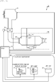
- Fig. 1 is an overall configuration diagram of a filter regeneration system 10.
- the filter regeneration system 10 includes: an engine 11 that serves as a power source of a vehicle; an ECU 12 that controls the engine 11; an aftertreatment device 20 that treats exhaust gas from the engine 11; and an in-vehicle instrument 30 that acquires information of the vehicle from the ECU 12 and displays the information of the vehicle for a driver.
- the aftertreatment device 20 includes: a DPF 21 that performs after treatment of the exhaust gas from the engine 11; a temperature sensor 22 that acquires a temperature T EXH of the exhaust gas flowing into the DPF 21; a flow rate sensor 23 that acquires a flow rate M EXH of the exhaust gas flowing into the DPF 21; and a pressure sensor 24 that detects a differential pressure P EXH between the exhaust gas on an upstream side of the DPF and the exhaust gas on a downstream side of the DPF.
- the in-vehicle instrument 30 includes: a remaining soot amount display section 31 that displays an integrated soot accumulation amount or a remaining soot amount; a DPF lamp 32 that notifies the driver of a state of the DPF by flashing or lighting; and a DPF switch 33 that is operated by the driver who has determined the state of the DPF from a state of the DPF lamp. Note that, when the driver operates the DPF switch 33 to instruct the ECU 12 to initiate DPF regeneration, the ECU 12 instructs the engine 11 to initiate the DPF regeneration.
- the remaining soot amount display section 31 may display the remaining soot amount by arranging bars in different lengths as in Fig. 7 , which will be described below, or may display a remaining time. Alternatively, the remaining soot amount display section 31 may display estimated finish time by referring to current time. The remaining soot amount display section 31 is instructed by a display instruction section 120E, which will be described below.
- the ECU 12 is connected to the engine 11 and the aftertreatment device 20 and calculates the integrated soot accumulation amount or the remaining soot amount in a specified cycle on the basis of the information acquired from the aftertreatment device 20 (the temperature T EXH , the flow rate M EXH , and the differential pressure P EXH of the exhaust gas flowing into the DPF 21).
- the ECU 12 Upon the DPF regeneration, the ECU 12 calculates an integrated soot reduction amount as a burned soot amount in a specified cycle from the temperature T EXH and the like of the exhaust gas and subtracts the integrated soot reduction amount from the integrated soot accumulation amount. In this way, the remaining soot amount at the time when soot is burned off is calculated.
- the specified cycle may be a short cycle, such as 20 milliseconds, that can be displayed such that it seems for the driver that the cycle is constantly updated.
- the specified cycle may be a relatively long cycle, such as one second, 30 seconds, or one minute, so that the driver can recognize an update cycle.
- a remaining soot amount calculation method For the DPF regeneration, two models are defined as a remaining soot amount calculation method.
- One of the models is a physical model to calculate the remaining soot amount in the specified cycle as described above.
- the other model is a time model to calculate the remaining soot amount on the basis of the information acquired from the aftertreatment device 20 (the temperature T EXH , the flow rate M EXH , and the differential pressure P EXH of the exhaust gas flowing into the DPF 21) only at the initiation of the DPF regeneration and thereafter reduce the calculated remaining soot amount per the specified cycle in a specified period (based on a specified linear function that defines a linear relationship between the time and the remaining soot amount).
- the specified period may be a time (the longest time) that is taken until the remaining soot amount becomes zero in the case where the vehicle travels on a congested road, for example.
- the specified period may be a time (a standard time) that is taken until the remaining soot amount becomes zero in the case where the vehicle travels on a relatively major road, such as a highway, at a legal speed.
- the specified period can be set to any time, such as a value based on an experiment or a value acquired from a calculation result based on each type of the information from the ECU 12 at the initiation of the DPF regeneration.
- the exhaust gas flow rate M EXH may not be the value acquired from the flow rate sensor 23 but may be a value calculated from an intake airflow rate measured value, an opening amount of an EGR valve 13, an engine speed detected by a sensor, and the like.
- the remaining soot amount may be calculated from the engine speed and an engine load that is computed from a fuel injection amount (an instruction value from the ECU 12 to the engine 11).
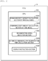
- the ECU 12 has a central processing unit (CPU) 120 that includes: a remaining soot amount calculation section 120A by the physical model; a remaining soot amount calculation section 120B by the time model; a regeneration model selection section 120C that selects a calculation result of one of the remaining soot amount by the physical model and the remaining soot amount by the time model; an estimated remaining DPF regeneration time calculation section 120D that calculates an estimated remaining DPF regeneration time on the basis of the selected calculation result; and the display instruction section 120E that provides a display instruction to the in-vehicle instrument 30 so as to make the in-vehicle instrument 30 display the calculated estimated remaining DPF regeneration time.
- CPU central processing unit
- Each of the remaining soot amount calculation section 120A by the physical model, the remaining soot amount calculation section 120B by the time model, the regeneration model selection section 120C, the estimated remaining DPF regeneration time calculation section 120D, and the display instruction section 120E is realized by software and/or hardware.
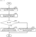
- the ECU 12 executes processing as illustrated in Fig. 3 .
- the remaining soot amount calculation section 120A by the physical model calculates the integrated soot accumulation amount or the remaining soot amount (SP11).
- the estimated remaining DPF regeneration time calculation section 120D converts the estimated remaining DPF regeneration time from the integrated soot accumulation amount or the remaining soot amount based on a graph illustrated in Fig. 5 , which will be described below, and calculates the estimated remaining DPF regeneration time (SP12).
- the display instruction section 120E instructs the remaining soot amount display section 31 of the in-vehicle instrument 30 to display the estimated remaining DPF regeneration time (SP13).
- contents of the display instructed to the in-vehicle instrument 30 by the display instruction section 120E may not only be the estimated remaining DPF regeneration time, and the display instruction section 120E may instruct the in-vehicle instrument 30 to display the integrated soot accumulation amount or the remaining soot amount.
- the ECU 12 executes processing as illustrated in Fig. 4 upon the DPF regeneration.
- the remaining soot amount calculation section 120A by the physical model calculates a remaining soot amount (Rp) by the physical model (SP21).
- the remaining soot amount calculation section 120B by the time model calculates a remaining soot amount (Rt) by the time model (SP22).
- the regeneration model selection section 120C compares the remaining soot amount (Rp) calculated by the physical model and the remaining soot amount (Rt) calculated by the time model and selects a larger value (a larger remaining soot amount) thereof (SP23).
- the estimated remaining DPF regeneration time calculation section 120D calculates an estimated remaining DPF regeneration time (Tp or Tt) that corresponds to the remaining soot amount (Rp or Rt) selected in step SP23.
- the display instruction section 120E instructs the in-vehicle instrument 30 to display the estimated remaining DPF regeneration time (Tp or Tt) (SP24, SP25). These types of the processing (SP21 to SP25) are repeatedly executed in a specified cycle.
- contents of the display instructed to the in-vehicle instrument 30 by the display instruction section 120E may not only be the estimated remaining DPF regeneration time (Tp or Tt), and the display instruction section 120E may instruct the in-vehicle instrument 30 to display the remaining soot amount (Rp or Rt) .
- Fig. 5 is a graph that is used when the remaining soot amount calculation section 120A by the physical model calculates the integrated soot accumulation amount or the remaining soot amount.
- Fig. 5 illustrates a relationship between a PM amount and a time taken to burn off PM for every temperature T EXH of the exhaust gas flowing into the DPF 21 in the case where the flow rate M EXH of the exhaust gas to the DPF 21 is constant.
- the PM can be regarded to be almost equal to the integrated soot accumulation amount or the remaining soot amount.
- a case where the temperature T EXH of the exhaust gas flowing into the DPF 21 is 550 °C is indicated by a solid line
- a case where the temperature T EXH of the exhaust gas flowing into the DPF 21 is 600 °C is indicated by a broken line
- a case where the temperature T EXH of the exhaust gas flowing into the DPF 21 is 650 °C is indicated by a dotted line.
- the physical model as illustrated in Fig. 5 is referred in the specified cycle, for example, at every 20 milliseconds. In this way, it is possible to calculate the PM amount or either one of the integrated soot accumulation amount and the remaining soot amount corresponding to the temperature T EXH and the flow rate M EXH of the exhaust gas flowing into the DPF 21 at the time. By comparing the remaining soot amount calculated at the time and the integrated soot accumulation amount at the initiation of the regeneration, a remaining soot amount rate can be calculated, and a relationship as the physical model indicated by a solid line in Fig. 6 is established.
- a period T1 in Fig. 6 in regard to the physical model indicated by the solid line, the remaining soot amount rate is hardly reduced because the temperature T EXH of the exhaust gas flowing into the DPF 21 is low (does not reach 550 °C) .
- the temperature T EXH of the exhaust gas flowing into the DPF 21 is stabilized at approximately 550 °C to 600 °C, and the remaining soot amount rate is reduced naturally.
- a reduction rate of the remaining soot amount rate is slowed because the temperature T EXH is reduced again.
- a graph of the display model indicated by a bold line in Fig. 6 is acquired by graphically illustrating the processing result in Fig. 4 .
- the graph by the physical model and a graph by the time model are compared, and a larger value on the remaining soot amount rate axis with respect to the same time axis is adopted for the graph.
- the graph of the display model is the same as the graph of the physical model
- the graph of the display model is the same as the graph of the time model. That is, the model having the higher remaining soot amount rate is selected as the display model and is actually displayed.
- Fig. 7 is a chart illustrating the remaining soot amount calculated by the remaining soot amount calculation section 120B by the time model.
- the integrated soot accumulation amount and the specified period based on the integrated soot accumulation amount are calculated at the initiation of the DPF regeneration (31A). Thereafter, the integrated soot accumulation amount is reduced at the certain rate at every certain time, so as to calculate (estimate) the remaining soot amount. Note that an example of displaying the remaining soot amount rate, which is acquired by comparing the integrated soot accumulation amount at the initiation of the regeneration and the remaining soot amount, instead of the remaining soot amount is illustrated herein.
- 31A is an image that is displayed in the remaining soot amount display section 31 when the remaining soot amount rate is 100%.
- the remaining soot amount rate is reduced equally from 100% to 80%, 60%, 40%, and 20%.
- An update cycle of the remaining soot amount rate is set as the specified cycle. Note that a dotted line in Fig. 6 represents a graph illustrating a relationship between the remaining soot amount rate by the time model and the time.
- the filter regeneration system 10 on the basis of the two models of the physical model and the time model, the integrated accumulation amount or the remaining soot amount, the estimated remaining DPF regeneration time, and the estimated DPF regeneration time are displayed on the in-vehicle instrument 30.
- the driver can recognize the time as an indication of terminating the DPF regeneration and thus can create an efficient travel plan for which the DPF regeneration is considered.
- the model having the estimation result of the longer time is adopted as the display model.
- the travel plan with a spare time can be created.
- this embodiment can also be applied to a case where the DPF regeneration is performed during travel (automatic regeneration) and a case where the DPF regeneration is performed by operating the DPF switch 33 by the driver and bringing the engine into a specified engine operation state when the vehicle is stopped (manual regeneration).
- the effects of this embodiment are particularly exerted when the embodiment is applied to the automatic regeneration. Because the engine operation state is changed from moment to moment in the automatic regeneration, a result that is not based on the estimation result by the time model is frequently produced.
- the driver can flexibly change the travel plan in accordance with the estimated finish time that is displayed from moment to moment. Therefore, the efficient travel plan can be created overall.
- the physical model or the time model may be selected by comparing the estimated remaining DPF regeneration times.
- the physical model is used to create the display model.
- the PM amount or the remaining soot amount which corresponds to the temperature T EXH and the flow rate M EXH of the exhaust gas flowing into the DPF 21 at the time, is constantly calculated in the specified cycle.
- the display model may be calculated in the same manner as the calculation of the time model.
- the temperature T EXH , the flow rate M EXH , and the like of the exhaust gas flowing into the DPF 21 may be checked only in a certain period at the initiation of the regeneration, and the display may be made on the basis of the estimated display model based on those values.
- the present invention may cooperate with a car navigation system.
- a traffic jam condition and the legal speed of a road to be traveled may be acquired from the car navigation system, and the estimated remaining DPF regeneration time may be calculated on the basis of those types of information.
Landscapes
- Engineering & Computer Science (AREA)
- Chemical & Material Sciences (AREA)
- Combustion & Propulsion (AREA)
- Mechanical Engineering (AREA)
- General Engineering & Computer Science (AREA)
- Processes For Solid Components From Exhaust (AREA)
- Exhaust Gas After Treatment (AREA)
Abstract
Description
- The present invention relates to a filter regeneration system, an ECU, and a filter regeneration program and is in particular suited for application to a filter regeneration system, an ECU, and a filter regeneration program displaying an estimated remaining filter regeneration time.
- Conventionally, a collection device referred to as a diesel particulate filter (DPF) has been known. The diesel particulate filter (DPF) collects particulate matter (PM) contained in exhaust gas of an internal combustion engine (an engine) (for example, see PTL 1). The DPF is a component that collects the PM from a diesel vehicle to prevent PM emissions to the atmosphere.
- In the vehicle provided with the DPF, in order to prevent deterioration of a filter function caused by clogging, DPF regeneration is performed to regenerate the DPF by burning the DPF using a heater or the like (in particular, burning off smut of the PM). Smut is also referred to as soot. This DPF regeneration is automatically initiated during travel by control of an engine control unit (ECU) controlling the engine. Meanwhile, in the case where the regeneration during the travel is insufficient, the DPF regeneration is possibly initiated by a driver's switch operation when the vehicle is stopped.
- A DPF system calculates a time used as an indication of terminating the DPF regeneration in advance, and terminates the DPF regeneration at the calculated time as the indication.
- PTL 1:
JP-A-2013-160045 - The time used as the indication of terminating the DPF regeneration is only used by the ECU to control the DPF regeneration and is not notified to the driver. Accordingly, the driver cannot recognize the time as the indication of terminating the DPF regeneration and thus cannot create an efficient travel plan for which the DPF regeneration is considered.
- In view of the above, the present invention has a purpose of proposing a filter regeneration system, an ECU, and a filter regeneration program capable of creating an efficient travel plan for a driver by notifying the driver of an estimated remaining DPF regeneration time.
- In order to achieve the above purpose, the present invention is a filter regeneration system for a DPF collecting particulate matter. The filter regeneration system includes an ECU that controls filter regeneration processing for the DPF. The ECU calculates a remaining soot amount (Rp) at a current time point on the basis of a physical model indicative of an actual remaining soot amount, calculates a remaining soot amount (Rt) at the current time point on the basis of a time model indicative of a theoretical remaining soot amount, calculates an estimated remaining DPF regeneration time (Tp, Tt) at the current time point on the basis of larger one of the remaining soot amounts (Rp, Rt), and notifies a driver of the estimated remaining DPF regeneration time (Tp, Tt). Advantageous Effects of Invention
- According to the present invention, an efficient travel plan can be created for the driver by notifying the driver of the estimated remaining DPF regeneration time.
-
-
Fig. 1 is an overall configuration diagram of a filter regeneration system. -
Fig. 2 is an internal configuration diagram of an ECU. -
Fig. 3 is a flowchart of estimated remaining DPF regeneration time calculation processing. -
Fig. 4 is a flowchart of the estimated remaining DPF regeneration time calculation processing at the time when a DPF is regenerated. -
Fig. 5 is a conceptual graph of a physical model. -
Fig. 6 is a conceptual graph of a display model. -
Fig. 7 is a conceptual chart of a time model. - An embodiment of the present invention will be described with reference to the drawings. Note that the following description does not limit the present invention and can appropriately be changed within the scope of the present invention.
-
Fig. 1 is an overall configuration diagram of afilter regeneration system 10. Thefilter regeneration system 10 includes: anengine 11 that serves as a power source of a vehicle; anECU 12 that controls theengine 11; anaftertreatment device 20 that treats exhaust gas from theengine 11; and an in-vehicle instrument 30 that acquires information of the vehicle from theECU 12 and displays the information of the vehicle for a driver. - The
aftertreatment device 20 includes: a DPF 21 that performs after treatment of the exhaust gas from theengine 11; a temperature sensor 22 that acquires a temperature TEXH of the exhaust gas flowing into the DPF 21; aflow rate sensor 23 that acquires a flow rate MEXH of the exhaust gas flowing into the DPF 21; and apressure sensor 24 that detects a differential pressure PEXH between the exhaust gas on an upstream side of the DPF and the exhaust gas on a downstream side of the DPF. - The in-
vehicle instrument 30 includes: a remaining sootamount display section 31 that displays an integrated soot accumulation amount or a remaining soot amount; aDPF lamp 32 that notifies the driver of a state of the DPF by flashing or lighting; and aDPF switch 33 that is operated by the driver who has determined the state of the DPF from a state of the DPF lamp. Note that, when the driver operates theDPF switch 33 to instruct theECU 12 to initiate DPF regeneration, theECU 12 instructs theengine 11 to initiate the DPF regeneration. - The remaining soot
amount display section 31 may display the remaining soot amount by arranging bars in different lengths as inFig. 7 , which will be described below, or may display a remaining time. Alternatively, the remaining sootamount display section 31 may display estimated finish time by referring to current time. The remaining sootamount display section 31 is instructed by adisplay instruction section 120E, which will be described below. - The
ECU 12 is connected to theengine 11 and theaftertreatment device 20 and calculates the integrated soot accumulation amount or the remaining soot amount in a specified cycle on the basis of the information acquired from the aftertreatment device 20 (the temperature TEXH, the flow rate MEXH, and the differential pressure PEXH of the exhaust gas flowing into the DPF 21). - Upon the DPF regeneration, the
ECU 12 calculates an integrated soot reduction amount as a burned soot amount in a specified cycle from the temperature TEXH and the like of the exhaust gas and subtracts the integrated soot reduction amount from the integrated soot accumulation amount. In this way, the remaining soot amount at the time when soot is burned off is calculated. - The specified cycle may be a short cycle, such as 20 milliseconds, that can be displayed such that it seems for the driver that the cycle is constantly updated. Alternatively, the specified cycle may be a relatively long cycle, such as one second, 30 seconds, or one minute, so that the driver can recognize an update cycle.
- For the DPF regeneration, two models are defined as a remaining soot amount calculation method. One of the models is a physical model to calculate the remaining soot amount in the specified cycle as described above. The other model is a time model to calculate the remaining soot amount on the basis of the information acquired from the aftertreatment device 20 (the temperature TEXH, the flow rate MEXH, and the differential pressure PEXH of the exhaust gas flowing into the DPF 21) only at the initiation of the DPF regeneration and thereafter reduce the calculated remaining soot amount per the specified cycle in a specified period (based on a specified linear function that defines a linear relationship between the time and the remaining soot amount).
- The specified period may be a time (the longest time) that is taken until the remaining soot amount becomes zero in the case where the vehicle travels on a congested road, for example. Alternatively, the specified period may be a time (a standard time) that is taken until the remaining soot amount becomes zero in the case where the vehicle travels on a relatively major road, such as a highway, at a legal speed. The specified period can be set to any time, such as a value based on an experiment or a value acquired from a calculation result based on each type of the information from the
ECU 12 at the initiation of the DPF regeneration. - The exhaust gas flow rate MEXH may not be the value acquired from the
flow rate sensor 23 but may be a value calculated from an intake airflow rate measured value, an opening amount of anEGR valve 13, an engine speed detected by a sensor, and the like. In addition, the remaining soot amount may be calculated from the engine speed and an engine load that is computed from a fuel injection amount (an instruction value from theECU 12 to the engine 11). - As illustrated in
Fig. 2 , theECU 12 has a central processing unit (CPU) 120 that includes: a remaining sootamount calculation section 120A by the physical model; a remaining sootamount calculation section 120B by the time model; a regenerationmodel selection section 120C that selects a calculation result of one of the remaining soot amount by the physical model and the remaining soot amount by the time model; an estimated remaining DPF regenerationtime calculation section 120D that calculates an estimated remaining DPF regeneration time on the basis of the selected calculation result; and thedisplay instruction section 120E that provides a display instruction to the in-vehicle instrument 30 so as to make the in-vehicle instrument 30 display the calculated estimated remaining DPF regeneration time. - Each of the remaining soot
amount calculation section 120A by the physical model, the remaining sootamount calculation section 120B by the time model, the regenerationmodel selection section 120C, the estimated remaining DPF regenerationtime calculation section 120D, and thedisplay instruction section 120E is realized by software and/or hardware. - The
ECU 12 executes processing as illustrated inFig. 3 . First, the remaining sootamount calculation section 120A by the physical model calculates the integrated soot accumulation amount or the remaining soot amount (SP11). Next, the estimated remaining DPF regenerationtime calculation section 120D converts the estimated remaining DPF regeneration time from the integrated soot accumulation amount or the remaining soot amount based on a graph illustrated inFig. 5 , which will be described below, and calculates the estimated remaining DPF regeneration time (SP12). Finally, thedisplay instruction section 120E instructs the remaining sootamount display section 31 of the in-vehicle instrument 30 to display the estimated remaining DPF regeneration time (SP13). These types of the processing (SP11 to SP13) are repeatedly executed in a specified cycle. Note that contents of the display instructed to the in-vehicle instrument 30 by thedisplay instruction section 120E may not only be the estimated remaining DPF regeneration time, and thedisplay instruction section 120E may instruct the in-vehicle instrument 30 to display the integrated soot accumulation amount or the remaining soot amount. - In addition, the
ECU 12 executes processing as illustrated inFig. 4 upon the DPF regeneration. First, the remaining sootamount calculation section 120A by the physical model calculates a remaining soot amount (Rp) by the physical model (SP21). Next, the remaining sootamount calculation section 120B by the time model calculates a remaining soot amount (Rt) by the time model (SP22). - Next, the regeneration
model selection section 120C compares the remaining soot amount (Rp) calculated by the physical model and the remaining soot amount (Rt) calculated by the time model and selects a larger value (a larger remaining soot amount) thereof (SP23). The estimated remaining DPF regenerationtime calculation section 120D calculates an estimated remaining DPF regeneration time (Tp or Tt) that corresponds to the remaining soot amount (Rp or Rt) selected in step SP23. Thedisplay instruction section 120E instructs the in-vehicle instrument 30 to display the estimated remaining DPF regeneration time (Tp or Tt) (SP24, SP25). These types of the processing (SP21 to SP25) are repeatedly executed in a specified cycle. Note that contents of the display instructed to the in-vehicle instrument 30 by thedisplay instruction section 120E may not only be the estimated remaining DPF regeneration time (Tp or Tt), and thedisplay instruction section 120E may instruct the in-vehicle instrument 30 to display the remaining soot amount (Rp or Rt) . -
Fig. 5 is a graph that is used when the remaining sootamount calculation section 120A by the physical model calculates the integrated soot accumulation amount or the remaining soot amount.Fig. 5 illustrates a relationship between a PM amount and a time taken to burn off PM for every temperature TEXH of the exhaust gas flowing into the DPF 21 in the case where the flow rate MEXH of the exhaust gas to the DPF 21 is constant. Here, the PM can be regarded to be almost equal to the integrated soot accumulation amount or the remaining soot amount. InFig. 5 , a case where the temperature TEXH of the exhaust gas flowing into the DPF 21 is 550 °C is indicated by a solid line, a case where the temperature TEXH of the exhaust gas flowing into the DPF 21 is 600 °C is indicated by a broken line, and a case where the temperature TEXH of the exhaust gas flowing into the DPF 21 is 650 °C is indicated by a dotted line. - The physical model as illustrated in
Fig. 5 is referred in the specified cycle, for example, at every 20 milliseconds. In this way, it is possible to calculate the PM amount or either one of the integrated soot accumulation amount and the remaining soot amount corresponding to the temperature TEXH and the flow rate MEXH of the exhaust gas flowing into the DPF 21 at the time. By comparing the remaining soot amount calculated at the time and the integrated soot accumulation amount at the initiation of the regeneration, a remaining soot amount rate can be calculated, and a relationship as the physical model indicated by a solid line inFig. 6 is established. - In a period T1 in
Fig. 6 , in regard to the physical model indicated by the solid line, the remaining soot amount rate is hardly reduced because the temperature TEXH of the exhaust gas flowing into the DPF 21 is low (does not reach 550 °C) . In a period T2, the temperature TEXH of the exhaust gas flowing into the DPF 21 is stabilized at approximately 550 °C to 600 °C, and the remaining soot amount rate is reduced naturally. In a period T3, a reduction rate of the remaining soot amount rate is slowed because the temperature TEXH is reduced again. - A graph of the display model indicated by a bold line in
Fig. 6 is acquired by graphically illustrating the processing result inFig. 4 . In the case where the processing in steps SP23 to SP25 is illustrated graphically, the graph by the physical model and a graph by the time model are compared, and a larger value on the remaining soot amount rate axis with respect to the same time axis is adopted for the graph. - More specifically, in periods S1 and S3, the graph of the display model is the same as the graph of the physical model, and in periods S2 and S4, the graph of the display model is the same as the graph of the time model. That is, the model having the higher remaining soot amount rate is selected as the display model and is actually displayed.
-
Fig. 7 is a chart illustrating the remaining soot amount calculated by the remaining sootamount calculation section 120B by the time model. As described above, in the processing based on the time model, the integrated soot accumulation amount and the specified period based on the integrated soot accumulation amount are calculated at the initiation of the DPF regeneration (31A). Thereafter, the integrated soot accumulation amount is reduced at the certain rate at every certain time, so as to calculate (estimate) the remaining soot amount. Note that an example of displaying the remaining soot amount rate, which is acquired by comparing the integrated soot accumulation amount at the initiation of the regeneration and the remaining soot amount, instead of the remaining soot amount is illustrated herein. - 31A is an image that is displayed in the remaining soot
amount display section 31 when the remaining soot amount rate is 100%. In the cases where the remaining soot amount rate is only based on the time model and time elapses at the same intervals among 31A, 31B, 31C, 31D, and 31E, the remaining soot amount rate is reduced equally from 100% to 80%, 60%, 40%, and 20%. An update cycle of the remaining soot amount rate is set as the specified cycle. Note that a dotted line inFig. 6 represents a graph illustrating a relationship between the remaining soot amount rate by the time model and the time. - As it has been described so far, in the
filter regeneration system 10 according to this embodiment, on the basis of the two models of the physical model and the time model, the integrated accumulation amount or the remaining soot amount, the estimated remaining DPF regeneration time, and the estimated DPF regeneration time are displayed on the in-vehicle instrument 30. - Thus, the driver can recognize the time as an indication of terminating the DPF regeneration and thus can create an efficient travel plan for which the DPF regeneration is considered. In addition, of the two models of the physical model and the time model, the model having the estimation result of the longer time is adopted as the display model. Thus, the travel plan with a spare time can be created.
- Note that this embodiment can also be applied to a case where the DPF regeneration is performed during travel (automatic regeneration) and a case where the DPF regeneration is performed by operating the
DPF switch 33 by the driver and bringing the engine into a specified engine operation state when the vehicle is stopped (manual regeneration). The effects of this embodiment are particularly exerted when the embodiment is applied to the automatic regeneration. Because the engine operation state is changed from moment to moment in the automatic regeneration, a result that is not based on the estimation result by the time model is frequently produced. - However, even when the DPF regeneration time is longer than the estimation result by the time model, the result is corrected by the estimation result by the physical model, and the result as of the display model is displayed on the in-
vehicle instrument 30. Thus, the slowed reduction of the remaining soot amount, the slowed reduction of the remaining time, or a delay of the estimated finish time is displayed on the in-vehicle instrument 30. In this case, the driver can flexibly change the travel plan in accordance with the estimated finish time that is displayed from moment to moment. Therefore, the efficient travel plan can be created overall. - In the above-described embodiment, the description has been made on the case where the physical model or the time model is selected by comparing the remaining soot amounts. However, the physical model or the time model may be selected by comparing the estimated remaining DPF regeneration times.
- In addition, in the above-described embodiment, the physical model is used to create the display model. Thus, the PM amount or the remaining soot amount, which corresponds to the temperature TEXH and the flow rate MEXH of the exhaust gas flowing into the DPF 21 at the time, is constantly calculated in the specified cycle. However, the display model may be calculated in the same manner as the calculation of the time model.
- More specifically, the temperature TEXH, the flow rate MEXH, and the like of the exhaust gas flowing into the DPF 21 may be checked only in a certain period at the initiation of the regeneration, and the display may be made on the basis of the estimated display model based on those values.
- Furthermore, the present invention may cooperate with a car navigation system. A traffic jam condition and the legal speed of a road to be traveled may be acquired from the car navigation system, and the estimated remaining DPF regeneration time may be calculated on the basis of those types of information.
-
- 10:
- Filter regeneration system
- 11:
- Engine
- 12:
- ECU
- 21:
- DPF
- 22:
- Temperature sensor
- 23:
- Flow rate sensor
- 30:
- In-vehicle instrument
Claims (6)
- A filter regeneration system (10) for a DPF (21) collecting particulate matter, the filter regeneration system comprising:an ECU (12) that controls filter regeneration processing for the DPF (21), whereinthe ECU (12)calculates a remaining soot amount (Rp) at a current time point on the basis of a physical model indicative of an actual remaining soot amount and calculates a remaining soot amount (Rt) at the current time point on the basis of a time model indicative of a theoretical remaining soot amount,calculates an estimated remaining DPF regeneration time (Tp, Tt) at the current time point on the basis of larger one of the remaining soot amounts (Rp, Rt), andnotifies a driver of the estimated remaining DPF regeneration time (Tp, Tt).
- The filter regeneration system according to claim 1, wherein
on the basis of the physical model, the ECU (12)
calculates a soot reduction amount in a specified cycle upon regeneration on the basis of a signal from a temperature sensor (22) measuring a temperature of exhaust gas flowing into the DPF (21) and a signal from a flow rate sensor (23) measuring a flow rate of the exhaust gas flowing into the DPF (21), and
calculates the remaining soot amount (Rp) at the current time point by subtracting the soot reduction amount from an integrated soot accumulation amount that is acquired in a specified cycle upon the regeneration of the DPF (21). - The filter regeneration system according to claim 1, wherein
on the basis of the time model, the ECU (12)
calculates the remaining soot amount (Rt) at the current time point on the basis of a linear function indicative of a linear relationship between time and the remaining soot amount from an integrated soot accumulation amount, which is acquired at initiation of the regeneration of the DPF (21), and a specified period. - The filter regeneration system according to claim 1, wherein
the ECU (12)
displays the estimated remaining DPF regeneration time (Tp, Tt) in an in-vehicle instrument (30). - An ECU (12) that controls regeneration processing of a DPF (21) collecting particulate matter, wherein
the ECU (12)
calculates a remaining soot amount (Rp) at a current time point on the basis of a physical model indicative of an actual remaining soot amount and calculates a remaining soot amount (Rt) at the current time point on the basis of a time model indicative of a theoretical remaining soot amount,
calculates an estimated remaining DPF regeneration time (Tp, Tt) at the current time point on the basis of larger one of the remaining soot amounts (Rp, Rt), and
notifies a driver of the estimated remaining DPF regeneration time (Tp, Tt). - A filter regeneration program for a DPF (21) collecting particulate matter, wherein
the filter regeneration program makes a computer realize a function of calculating a remaining soot amount (Rp) at a current time point on the basis of a physical model indicative of an actual remaining soot amount and calculating a remaining soot amount (Rt) at the current time point on the basis of a time model indicative of a theoretical remaining soot amount,
a function of calculating an estimated remaining DPF regeneration time (Tp, Tt) at the current time point on the basis of larger one of the remaining soot amounts (Rp, Rt), and
a function of notifying a driver of the estimated remaining DPF regeneration time (Tp, Tt).
Applications Claiming Priority (2)
| Application Number | Priority Date | Filing Date | Title |
|---|---|---|---|
| JP2016078779 | 2016-04-11 | ||
| PCT/JP2017/004656 WO2017179277A1 (en) | 2016-04-11 | 2017-02-09 | Filter reproduction system, ecu and filter reproduction program |
Publications (3)
| Publication Number | Publication Date |
|---|---|
| EP3444455A1 true EP3444455A1 (en) | 2019-02-20 |
| EP3444455A4 EP3444455A4 (en) | 2019-04-24 |
| EP3444455B1 EP3444455B1 (en) | 2020-04-08 |
Family
ID=60042546
Family Applications (1)
| Application Number | Title | Priority Date | Filing Date |
|---|---|---|---|
| EP17782096.6A Active EP3444455B1 (en) | 2016-04-11 | 2017-02-09 | Filter reproduction system, ecu and filter reproduction program |
Country Status (8)
| Country | Link |
|---|---|
| EP (1) | EP3444455B1 (en) |
| JP (1) | JP6670530B2 (en) |
| CN (1) | CN109072745B (en) |
| AU (1) | AU2017248873A1 (en) |
| ES (1) | ES2794846T3 (en) |
| SG (1) | SG11201807958UA (en) |
| TW (1) | TWI708890B (en) |
| WO (1) | WO2017179277A1 (en) |
Families Citing this family (8)
| Publication number | Priority date | Publication date | Assignee | Title |
|---|---|---|---|---|
| CN110206616A (en) * | 2019-06-28 | 2019-09-06 | 安徽江淮汽车集团股份有限公司 | A kind of indicating means of particulate filter regeneration state, device and system |
| CN113404575B (en) * | 2020-03-17 | 2022-11-08 | 联合汽车电子有限公司 | GPF regeneration optimization method and GPF regeneration opportunity evaluation system |
| CN111810280A (en) * | 2020-04-26 | 2020-10-23 | 东风商用车有限公司 | System for DPF carbon loading capacity early warning |
| CN111980791B (en) * | 2020-09-02 | 2021-10-29 | 潍柴动力股份有限公司 | A data processing method and system |
| CN113448270B (en) * | 2021-06-24 | 2022-08-30 | 瑞立集团瑞安汽车零部件有限公司 | Regeneration control method for drying equipment in whole vehicle air treatment system |
| CN115898601B (en) * | 2022-11-21 | 2025-07-18 | 潍柴动力股份有限公司 | Regeneration control method and related device for particle catcher |
| CN117248988A (en) * | 2023-11-07 | 2023-12-19 | 中国第一汽车股份有限公司 | Particle trap regeneration interruption method, device, electronic device and storage medium |
| WO2025142075A1 (en) * | 2023-12-27 | 2025-07-03 | 株式会社クボタ | Information display system, information display method, computer program, and work vehicle |
Family Cites Families (10)
| Publication number | Priority date | Publication date | Assignee | Title |
|---|---|---|---|---|
| JP4333180B2 (en) * | 2003-03-27 | 2009-09-16 | いすゞ自動車株式会社 | Exhaust gas purification system |
| JP3925484B2 (en) * | 2003-10-29 | 2007-06-06 | マツダ株式会社 | Engine control device |
| JP4325565B2 (en) * | 2005-02-10 | 2009-09-02 | 日産自動車株式会社 | Exhaust gas purification device and exhaust gas purification method for internal combustion engine |
| EP2032810B1 (en) * | 2006-05-18 | 2012-03-14 | Clean Diesel Technologies, Inc. | Improvements in diesel particulate control |
| JP5206644B2 (en) * | 2009-10-22 | 2013-06-12 | 株式会社豊田自動織機 | Diesel engine exhaust gas purification system |
| FR2966514A3 (en) * | 2010-10-22 | 2012-04-27 | Renault Sa | METHOD FOR DETERMINING THE HOURS OF REGENERATIONS OF A PARTICLE FILTER |
| US9140169B2 (en) * | 2011-11-17 | 2015-09-22 | GM Global Technology Operations LLC | Method for controlling regeneration within an after-treatment component of a compression-ignition engine |
| KR101880307B1 (en) * | 2011-12-23 | 2018-07-20 | 두산인프라코어 주식회사 | Forced Regeneration Control Machine for Diesel Particulate Filter |
| GB2513586A (en) * | 2013-04-30 | 2014-11-05 | Gm Global Tech Operations Inc | Method of controlling a diesel particulate filter |
| US20150088399A1 (en) * | 2013-09-24 | 2015-03-26 | GM Global Technology Operations LLC | Exhaust system and method of estimating diesel particulate filter soot loading for same |
-
2017
- 2017-02-09 TW TW106104262A patent/TWI708890B/en active
- 2017-02-09 CN CN201780022772.7A patent/CN109072745B/en active Active
- 2017-02-09 EP EP17782096.6A patent/EP3444455B1/en active Active
- 2017-02-09 SG SG11201807958UA patent/SG11201807958UA/en unknown
- 2017-02-09 AU AU2017248873A patent/AU2017248873A1/en not_active Abandoned
- 2017-02-09 WO PCT/JP2017/004656 patent/WO2017179277A1/en not_active Ceased
- 2017-02-09 ES ES17782096T patent/ES2794846T3/en active Active
- 2017-02-09 JP JP2018511895A patent/JP6670530B2/en active Active
Also Published As
| Publication number | Publication date |
|---|---|
| JPWO2017179277A1 (en) | 2018-11-08 |
| CN109072745A (en) | 2018-12-21 |
| CN109072745B (en) | 2020-12-22 |
| WO2017179277A1 (en) | 2017-10-19 |
| SG11201807958UA (en) | 2018-10-30 |
| TW201741546A (en) | 2017-12-01 |
| AU2017248873A1 (en) | 2018-10-11 |
| EP3444455A4 (en) | 2019-04-24 |
| JP6670530B2 (en) | 2020-03-25 |
| ES2794846T3 (en) | 2020-11-19 |
| EP3444455B1 (en) | 2020-04-08 |
| TWI708890B (en) | 2020-11-01 |
Similar Documents
| Publication | Publication Date | Title |
|---|---|---|
| EP3444455B1 (en) | Filter reproduction system, ecu and filter reproduction program | |
| US11073060B2 (en) | Method for optimizing an active regeneration of a diesel particulate filter | |
| US10161845B2 (en) | Method for monitoring a particulate filter | |
| US7474953B2 (en) | Process for determining particle emission in the exhaust fume stream from an internal combustion engine | |
| JP4385775B2 (en) | Exhaust gas purification device for internal combustion engine | |
| US8935953B2 (en) | Adaptive soot mass estimation in a vehicle exhaust after-treatment device | |
| EP1905991A1 (en) | Control method of exhaust gas purification system and exhaust gas purification system | |
| CN108252780B (en) | System and method for regenerating a particulate filter in a motor vehicle | |
| JP5034536B2 (en) | Exhaust gas purification device for in-vehicle internal combustion engine | |
| GB2479196A (en) | Method for regenerating a particulate filter using a navigation system | |
| US8631644B2 (en) | Method for operating post injections of fuel in an internal combustion engine | |
| US11274589B2 (en) | Method for timing a regeneration process | |
| JP4816606B2 (en) | Exhaust gas purification system for internal combustion engine | |
| EP2581572B1 (en) | Exhaust-gas purification system | |
| US20030131586A1 (en) | Deterioration determining for an exhaust gas purifier of an internal-combustion engine | |
| CN108952910B (en) | System and method for controlling bypass of exhaust aftertreatment device | |
| US20140060010A1 (en) | Method for the regeneration of a carbon particulate filter | |
| US20240093625A1 (en) | Method for operating a particle filter taking the ash quantity into consideration | |
| GB2532977A (en) | A method of scheduling the regeneration of a lean NOx trap | |
| EP2980377A1 (en) | Exhaust gas purification apparatus for internal combustion engine | |
| JP2008215218A (en) | In-vehicle internal combustion engine fuel level warning device | |
| JP2018204596A (en) | Engine exhaust treatment equipment | |
| JP4259944B2 (en) | Method for determining the amount of particulate accumulated in a particulate filter | |
| JP5799591B2 (en) | Internal combustion engine control device | |
| JP2008286208A (en) | Method for determining the amount of particulate accumulated in a particulate filter |
Legal Events
| Date | Code | Title | Description |
|---|---|---|---|
| STAA | Information on the status of an ep patent application or granted ep patent |
Free format text: STATUS: THE INTERNATIONAL PUBLICATION HAS BEEN MADE |
|
| PUAI | Public reference made under article 153(3) epc to a published international application that has entered the european phase |
Free format text: ORIGINAL CODE: 0009012 |
|
| STAA | Information on the status of an ep patent application or granted ep patent |
Free format text: STATUS: REQUEST FOR EXAMINATION WAS MADE |
|
| 17P | Request for examination filed |
Effective date: 20181112 |
|
| AK | Designated contracting states |
Kind code of ref document: A1 Designated state(s): AL AT BE BG CH CY CZ DE DK EE ES FI FR GB GR HR HU IE IS IT LI LT LU LV MC MK MT NL NO PL PT RO RS SE SI SK SM TR |
|
| AX | Request for extension of the european patent |
Extension state: BA ME |
|
| REG | Reference to a national code |
Ref country code: DE Ref legal event code: R079 Ref document number: 602017014556 Country of ref document: DE Free format text: PREVIOUS MAIN CLASS: F01N0003023000 Ipc: F01N0009000000 |
|
| A4 | Supplementary search report drawn up and despatched |
Effective date: 20190321 |
|
| RIC1 | Information provided on ipc code assigned before grant |
Ipc: F01N 3/24 20060101ALI20190315BHEP Ipc: F01N 9/00 20060101AFI20190315BHEP Ipc: F01N 3/18 20060101ALI20190315BHEP Ipc: F01N 3/023 20060101ALI20190315BHEP |
|
| DAV | Request for validation of the european patent (deleted) | ||
| DAX | Request for extension of the european patent (deleted) | ||
| GRAP | Despatch of communication of intention to grant a patent |
Free format text: ORIGINAL CODE: EPIDOSNIGR1 |
|
| STAA | Information on the status of an ep patent application or granted ep patent |
Free format text: STATUS: GRANT OF PATENT IS INTENDED |
|
| INTG | Intention to grant announced |
Effective date: 20190916 |
|
| GRAS | Grant fee paid |
Free format text: ORIGINAL CODE: EPIDOSNIGR3 |
|
| GRAA | (expected) grant |
Free format text: ORIGINAL CODE: 0009210 |
|
| STAA | Information on the status of an ep patent application or granted ep patent |
Free format text: STATUS: THE PATENT HAS BEEN GRANTED |
|
| AK | Designated contracting states |
Kind code of ref document: B1 Designated state(s): AL AT BE BG CH CY CZ DE DK EE ES FI FR GB GR HR HU IE IS IT LI LT LU LV MC MK MT NL NO PL PT RO RS SE SI SK SM TR |
|
| REG | Reference to a national code |
Ref country code: AT Ref legal event code: REF Ref document number: 1254678 Country of ref document: AT Kind code of ref document: T Effective date: 20200415 Ref country code: CH Ref legal event code: EP |
|
| REG | Reference to a national code |
Ref country code: DE Ref legal event code: R096 Ref document number: 602017014556 Country of ref document: DE |
|
| REG | Reference to a national code |
Ref country code: IE Ref legal event code: FG4D |
|
| REG | Reference to a national code |
Ref country code: NL Ref legal event code: MP Effective date: 20200408 |
|
| REG | Reference to a national code |
Ref country code: LT Ref legal event code: MG4D |
|
| PG25 | Lapsed in a contracting state [announced via postgrant information from national office to epo] |
Ref country code: NL Free format text: LAPSE BECAUSE OF FAILURE TO SUBMIT A TRANSLATION OF THE DESCRIPTION OR TO PAY THE FEE WITHIN THE PRESCRIBED TIME-LIMIT Effective date: 20200408 Ref country code: LT Free format text: LAPSE BECAUSE OF FAILURE TO SUBMIT A TRANSLATION OF THE DESCRIPTION OR TO PAY THE FEE WITHIN THE PRESCRIBED TIME-LIMIT Effective date: 20200408 Ref country code: SE Free format text: LAPSE BECAUSE OF FAILURE TO SUBMIT A TRANSLATION OF THE DESCRIPTION OR TO PAY THE FEE WITHIN THE PRESCRIBED TIME-LIMIT Effective date: 20200408 Ref country code: IS Free format text: LAPSE BECAUSE OF FAILURE TO SUBMIT A TRANSLATION OF THE DESCRIPTION OR TO PAY THE FEE WITHIN THE PRESCRIBED TIME-LIMIT Effective date: 20200808 Ref country code: FI Free format text: LAPSE BECAUSE OF FAILURE TO SUBMIT A TRANSLATION OF THE DESCRIPTION OR TO PAY THE FEE WITHIN THE PRESCRIBED TIME-LIMIT Effective date: 20200408 Ref country code: GR Free format text: LAPSE BECAUSE OF FAILURE TO SUBMIT A TRANSLATION OF THE DESCRIPTION OR TO PAY THE FEE WITHIN THE PRESCRIBED TIME-LIMIT Effective date: 20200709 Ref country code: NO Free format text: LAPSE BECAUSE OF FAILURE TO SUBMIT A TRANSLATION OF THE DESCRIPTION OR TO PAY THE FEE WITHIN THE PRESCRIBED TIME-LIMIT Effective date: 20200708 Ref country code: PT Free format text: LAPSE BECAUSE OF FAILURE TO SUBMIT A TRANSLATION OF THE DESCRIPTION OR TO PAY THE FEE WITHIN THE PRESCRIBED TIME-LIMIT Effective date: 20200817 |
|
| REG | Reference to a national code |
Ref country code: AT Ref legal event code: MK05 Ref document number: 1254678 Country of ref document: AT Kind code of ref document: T Effective date: 20200408 |
|
| REG | Reference to a national code |
Ref country code: ES Ref legal event code: FG2A Ref document number: 2794846 Country of ref document: ES Kind code of ref document: T3 Effective date: 20201119 |
|
| PG25 | Lapsed in a contracting state [announced via postgrant information from national office to epo] |
Ref country code: HR Free format text: LAPSE BECAUSE OF FAILURE TO SUBMIT A TRANSLATION OF THE DESCRIPTION OR TO PAY THE FEE WITHIN THE PRESCRIBED TIME-LIMIT Effective date: 20200408 Ref country code: RS Free format text: LAPSE BECAUSE OF FAILURE TO SUBMIT A TRANSLATION OF THE DESCRIPTION OR TO PAY THE FEE WITHIN THE PRESCRIBED TIME-LIMIT Effective date: 20200408 Ref country code: LV Free format text: LAPSE BECAUSE OF FAILURE TO SUBMIT A TRANSLATION OF THE DESCRIPTION OR TO PAY THE FEE WITHIN THE PRESCRIBED TIME-LIMIT Effective date: 20200408 Ref country code: BG Free format text: LAPSE BECAUSE OF FAILURE TO SUBMIT A TRANSLATION OF THE DESCRIPTION OR TO PAY THE FEE WITHIN THE PRESCRIBED TIME-LIMIT Effective date: 20200708 |
|
| PG25 | Lapsed in a contracting state [announced via postgrant information from national office to epo] |
Ref country code: AL Free format text: LAPSE BECAUSE OF FAILURE TO SUBMIT A TRANSLATION OF THE DESCRIPTION OR TO PAY THE FEE WITHIN THE PRESCRIBED TIME-LIMIT Effective date: 20200408 |
|
| REG | Reference to a national code |
Ref country code: DE Ref legal event code: R097 Ref document number: 602017014556 Country of ref document: DE |
|
| PG25 | Lapsed in a contracting state [announced via postgrant information from national office to epo] |
Ref country code: RO Free format text: LAPSE BECAUSE OF FAILURE TO SUBMIT A TRANSLATION OF THE DESCRIPTION OR TO PAY THE FEE WITHIN THE PRESCRIBED TIME-LIMIT Effective date: 20200408 Ref country code: CZ Free format text: LAPSE BECAUSE OF FAILURE TO SUBMIT A TRANSLATION OF THE DESCRIPTION OR TO PAY THE FEE WITHIN THE PRESCRIBED TIME-LIMIT Effective date: 20200408 Ref country code: AT Free format text: LAPSE BECAUSE OF FAILURE TO SUBMIT A TRANSLATION OF THE DESCRIPTION OR TO PAY THE FEE WITHIN THE PRESCRIBED TIME-LIMIT Effective date: 20200408 Ref country code: EE Free format text: LAPSE BECAUSE OF FAILURE TO SUBMIT A TRANSLATION OF THE DESCRIPTION OR TO PAY THE FEE WITHIN THE PRESCRIBED TIME-LIMIT Effective date: 20200408 Ref country code: SM Free format text: LAPSE BECAUSE OF FAILURE TO SUBMIT A TRANSLATION OF THE DESCRIPTION OR TO PAY THE FEE WITHIN THE PRESCRIBED TIME-LIMIT Effective date: 20200408 Ref country code: DK Free format text: LAPSE BECAUSE OF FAILURE TO SUBMIT A TRANSLATION OF THE DESCRIPTION OR TO PAY THE FEE WITHIN THE PRESCRIBED TIME-LIMIT Effective date: 20200408 |
|
| PLBE | No opposition filed within time limit |
Free format text: ORIGINAL CODE: 0009261 |
|
| STAA | Information on the status of an ep patent application or granted ep patent |
Free format text: STATUS: NO OPPOSITION FILED WITHIN TIME LIMIT |
|
| PG25 | Lapsed in a contracting state [announced via postgrant information from national office to epo] |
Ref country code: SK Free format text: LAPSE BECAUSE OF FAILURE TO SUBMIT A TRANSLATION OF THE DESCRIPTION OR TO PAY THE FEE WITHIN THE PRESCRIBED TIME-LIMIT Effective date: 20200408 Ref country code: PL Free format text: LAPSE BECAUSE OF FAILURE TO SUBMIT A TRANSLATION OF THE DESCRIPTION OR TO PAY THE FEE WITHIN THE PRESCRIBED TIME-LIMIT Effective date: 20200408 |
|
| 26N | No opposition filed |
Effective date: 20210112 |
|
| PG25 | Lapsed in a contracting state [announced via postgrant information from national office to epo] |
Ref country code: SI Free format text: LAPSE BECAUSE OF FAILURE TO SUBMIT A TRANSLATION OF THE DESCRIPTION OR TO PAY THE FEE WITHIN THE PRESCRIBED TIME-LIMIT Effective date: 20200408 |
|
| PG25 | Lapsed in a contracting state [announced via postgrant information from national office to epo] |
Ref country code: MC Free format text: LAPSE BECAUSE OF FAILURE TO SUBMIT A TRANSLATION OF THE DESCRIPTION OR TO PAY THE FEE WITHIN THE PRESCRIBED TIME-LIMIT Effective date: 20200408 |
|
| REG | Reference to a national code |
Ref country code: BE Ref legal event code: MM Effective date: 20210228 |
|
| PG25 | Lapsed in a contracting state [announced via postgrant information from national office to epo] |
Ref country code: LU Free format text: LAPSE BECAUSE OF NON-PAYMENT OF DUE FEES Effective date: 20210209 Ref country code: LI Free format text: LAPSE BECAUSE OF NON-PAYMENT OF DUE FEES Effective date: 20210228 Ref country code: CH Free format text: LAPSE BECAUSE OF NON-PAYMENT OF DUE FEES Effective date: 20210228 |
|
| PG25 | Lapsed in a contracting state [announced via postgrant information from national office to epo] |
Ref country code: FR Free format text: LAPSE BECAUSE OF NON-PAYMENT OF DUE FEES Effective date: 20210228 Ref country code: IE Free format text: LAPSE BECAUSE OF NON-PAYMENT OF DUE FEES Effective date: 20210209 |
|
| PG25 | Lapsed in a contracting state [announced via postgrant information from national office to epo] |
Ref country code: BE Free format text: LAPSE BECAUSE OF NON-PAYMENT OF DUE FEES Effective date: 20210228 |
|
| PG25 | Lapsed in a contracting state [announced via postgrant information from national office to epo] |
Ref country code: CY Free format text: LAPSE BECAUSE OF FAILURE TO SUBMIT A TRANSLATION OF THE DESCRIPTION OR TO PAY THE FEE WITHIN THE PRESCRIBED TIME-LIMIT Effective date: 20200408 |
|
| PG25 | Lapsed in a contracting state [announced via postgrant information from national office to epo] |
Ref country code: HU Free format text: LAPSE BECAUSE OF FAILURE TO SUBMIT A TRANSLATION OF THE DESCRIPTION OR TO PAY THE FEE WITHIN THE PRESCRIBED TIME-LIMIT; INVALID AB INITIO Effective date: 20170209 |
|
| PG25 | Lapsed in a contracting state [announced via postgrant information from national office to epo] |
Ref country code: MK Free format text: LAPSE BECAUSE OF FAILURE TO SUBMIT A TRANSLATION OF THE DESCRIPTION OR TO PAY THE FEE WITHIN THE PRESCRIBED TIME-LIMIT Effective date: 20200408 |
|
| PG25 | Lapsed in a contracting state [announced via postgrant information from national office to epo] |
Ref country code: MT Free format text: LAPSE BECAUSE OF FAILURE TO SUBMIT A TRANSLATION OF THE DESCRIPTION OR TO PAY THE FEE WITHIN THE PRESCRIBED TIME-LIMIT Effective date: 20200408 |
|
| PGFP | Annual fee paid to national office [announced via postgrant information from national office to epo] |
Ref country code: DE Payment date: 20250422 Year of fee payment: 9 |
|
| PG25 | Lapsed in a contracting state [announced via postgrant information from national office to epo] |
Ref country code: TR Free format text: LAPSE BECAUSE OF FAILURE TO SUBMIT A TRANSLATION OF THE DESCRIPTION OR TO PAY THE FEE WITHIN THE PRESCRIBED TIME-LIMIT Effective date: 20200408 |
|
| PGFP | Annual fee paid to national office [announced via postgrant information from national office to epo] |
Ref country code: GB Payment date: 20260219 Year of fee payment: 10 |
|
| PGFP | Annual fee paid to national office [announced via postgrant information from national office to epo] |
Ref country code: ES Payment date: 20260319 Year of fee payment: 10 |
|
| PGFP | Annual fee paid to national office [announced via postgrant information from national office to epo] |
Ref country code: IT Payment date: 20260227 Year of fee payment: 10 |