EP3444454A1 - Blow-by gas heating device - Google Patents
Blow-by gas heating device Download PDFInfo
- Publication number
- EP3444454A1 EP3444454A1 EP17846639.7A EP17846639A EP3444454A1 EP 3444454 A1 EP3444454 A1 EP 3444454A1 EP 17846639 A EP17846639 A EP 17846639A EP 3444454 A1 EP3444454 A1 EP 3444454A1
- Authority
- EP
- European Patent Office
- Prior art keywords
- blow
- heat emitting
- gas
- oil separator
- oil
- Prior art date
- Legal status (The legal status is an assumption and is not a legal conclusion. Google has not performed a legal analysis and makes no representation as to the accuracy of the status listed.)
- Granted
Links
Images



Classifications
-
- F—MECHANICAL ENGINEERING; LIGHTING; HEATING; WEAPONS; BLASTING
- F01—MACHINES OR ENGINES IN GENERAL; ENGINE PLANTS IN GENERAL; STEAM ENGINES
- F01M—LUBRICATING OF MACHINES OR ENGINES IN GENERAL; LUBRICATING INTERNAL COMBUSTION ENGINES; CRANKCASE VENTILATING
- F01M13/00—Crankcase ventilating or breathing
- F01M13/04—Crankcase ventilating or breathing having means for purifying air before leaving crankcase, e.g. removing oil
-
- F—MECHANICAL ENGINEERING; LIGHTING; HEATING; WEAPONS; BLASTING
- F01—MACHINES OR ENGINES IN GENERAL; ENGINE PLANTS IN GENERAL; STEAM ENGINES
- F01M—LUBRICATING OF MACHINES OR ENGINES IN GENERAL; LUBRICATING INTERNAL COMBUSTION ENGINES; CRANKCASE VENTILATING
- F01M5/00—Heating, cooling, or controlling temperature of lubricant; Lubrication means facilitating engine starting
- F01M5/02—Conditioning lubricant for aiding engine starting, e.g. heating
- F01M5/021—Conditioning lubricant for aiding engine starting, e.g. heating by heating
-
- F—MECHANICAL ENGINEERING; LIGHTING; HEATING; WEAPONS; BLASTING
- F01—MACHINES OR ENGINES IN GENERAL; ENGINE PLANTS IN GENERAL; STEAM ENGINES
- F01M—LUBRICATING OF MACHINES OR ENGINES IN GENERAL; LUBRICATING INTERNAL COMBUSTION ENGINES; CRANKCASE VENTILATING
- F01M13/00—Crankcase ventilating or breathing
-
- F—MECHANICAL ENGINEERING; LIGHTING; HEATING; WEAPONS; BLASTING
- F01—MACHINES OR ENGINES IN GENERAL; ENGINE PLANTS IN GENERAL; STEAM ENGINES
- F01M—LUBRICATING OF MACHINES OR ENGINES IN GENERAL; LUBRICATING INTERNAL COMBUSTION ENGINES; CRANKCASE VENTILATING
- F01M5/00—Heating, cooling, or controlling temperature of lubricant; Lubrication means facilitating engine starting
-
- F—MECHANICAL ENGINEERING; LIGHTING; HEATING; WEAPONS; BLASTING
- F01—MACHINES OR ENGINES IN GENERAL; ENGINE PLANTS IN GENERAL; STEAM ENGINES
- F01M—LUBRICATING OF MACHINES OR ENGINES IN GENERAL; LUBRICATING INTERNAL COMBUSTION ENGINES; CRANKCASE VENTILATING
- F01M5/00—Heating, cooling, or controlling temperature of lubricant; Lubrication means facilitating engine starting
- F01M5/02—Conditioning lubricant for aiding engine starting, e.g. heating
- F01M5/021—Conditioning lubricant for aiding engine starting, e.g. heating by heating
- F01M2005/023—Oil sump with partition for facilitating heating of oil during starting
-
- F—MECHANICAL ENGINEERING; LIGHTING; HEATING; WEAPONS; BLASTING
- F01—MACHINES OR ENGINES IN GENERAL; ENGINE PLANTS IN GENERAL; STEAM ENGINES
- F01M—LUBRICATING OF MACHINES OR ENGINES IN GENERAL; LUBRICATING INTERNAL COMBUSTION ENGINES; CRANKCASE VENTILATING
- F01M13/00—Crankcase ventilating or breathing
- F01M13/0011—Breather valves
- F01M2013/0027—Breather valves with a de-icing or defrosting system
-
- F—MECHANICAL ENGINEERING; LIGHTING; HEATING; WEAPONS; BLASTING
- F01—MACHINES OR ENGINES IN GENERAL; ENGINE PLANTS IN GENERAL; STEAM ENGINES
- F01M—LUBRICATING OF MACHINES OR ENGINES IN GENERAL; LUBRICATING INTERNAL COMBUSTION ENGINES; CRANKCASE VENTILATING
- F01M13/00—Crankcase ventilating or breathing
- F01M13/04—Crankcase ventilating or breathing having means for purifying air before leaving crankcase, e.g. removing oil
- F01M2013/0438—Crankcase ventilating or breathing having means for purifying air before leaving crankcase, e.g. removing oil with a filter
-
- F—MECHANICAL ENGINEERING; LIGHTING; HEATING; WEAPONS; BLASTING
- F01—MACHINES OR ENGINES IN GENERAL; ENGINE PLANTS IN GENERAL; STEAM ENGINES
- F01M—LUBRICATING OF MACHINES OR ENGINES IN GENERAL; LUBRICATING INTERNAL COMBUSTION ENGINES; CRANKCASE VENTILATING
- F01M13/00—Crankcase ventilating or breathing
- F01M13/04—Crankcase ventilating or breathing having means for purifying air before leaving crankcase, e.g. removing oil
- F01M2013/0455—Crankcase ventilating or breathing having means for purifying air before leaving crankcase, e.g. removing oil with a de-icing or defrosting system
-
- F—MECHANICAL ENGINEERING; LIGHTING; HEATING; WEAPONS; BLASTING
- F01—MACHINES OR ENGINES IN GENERAL; ENGINE PLANTS IN GENERAL; STEAM ENGINES
- F01M—LUBRICATING OF MACHINES OR ENGINES IN GENERAL; LUBRICATING INTERNAL COMBUSTION ENGINES; CRANKCASE VENTILATING
- F01M13/00—Crankcase ventilating or breathing
- F01M13/04—Crankcase ventilating or breathing having means for purifying air before leaving crankcase, e.g. removing oil
- F01M2013/0472—Crankcase ventilating or breathing having means for purifying air before leaving crankcase, e.g. removing oil using heating means
Definitions
- the present invention relates to a blow-by gas heating apparatus mounted on a blow-by gas return apparatus-equipped engine for an industrial or traveling vehicle. Specifically, the present invention relates to a blow-by gas heating apparatus including a heat emitting structure abutted onto an oil separator that traps and removes oil from blow-by gas.
- blow-by gas is leakage of an air-fuel mixture or combustion gas from a combustion chamber of an internal combustion engine into a crankcase through a gap between a piston and a cylinder (specifically, through a gap between a piston ring and a cylinder). That is, blow-by gas contains unburned gas, exhaust gas, and what is called oil mist, which is a mixture of the foregoing and engine oil (hereinafter simply referred to as the oil).
- the entry of the blow-by gas into the crankcase causes deterioration of the engine oil, corrosion of metal, and contamination of the atmosphere.
- blow-by gas return apparatus that is, a mechanism that returns blow-by gas accumulated in the crankcase to an intake passage, so that the returned blow-by gas is mixed with a new air-fuel mixture and burned and thereby prevented from being released into the atmosphere as it is.
- blow-by gas contains not only oil mist but also moisture contained in exhaust gas, in some cases, returning the blow-by gas into the intake passage as it is works adversely.
- a blow-by gas return apparatus is provided with an oil separator for trapping and removing mainly an oil component in blow-by gas, in order to remove liquid components such as oil (oil mist) and water contained in blow-by gas as much as possible and return the blow-by gas to the intake passage.
- an oil separator for trapping and removing mainly an oil component in blow-by gas, in order to remove liquid components such as oil (oil mist) and water contained in blow-by gas as much as possible and return the blow-by gas to the intake passage.
- Patent Documents 1 and 2 discloses the oil separator as a ventilator (2)
- Patent Document 2 discloses the oil separator as a ventilator apparatus (1).
- the blow-by gas return apparatus including a pipe for returning blow-by gas to the intake passage is basically externally mounted on an engine and exposed outside and, therefore, tends to be susceptible to cold. That is, under an extremely low temperature condition such as -20°C to -30°C in northern countries in winter, cooled blow-by gas makes moisture in the blow-by gas freeze, possibly resulting in clogging.
- an oil separator externally mounted on an engine has a large surface area and tends to be cooled, inviting freezing of moisture in the blow-by gas contained therein.
- the frozen moisture not only hinders the blow-by gas returning function, but also may clog the retuning port for trapped oil, inviting an excessive accumulation of the oil inside the oil separator, whereby the oil separation function is hindered.
- the clogging may increase the internal pressure in the crankcase, which may result in unexpected oil leakage.
- Patent Document 2 which is the provision of an antifreeze cover, exhibits the effect to some extent. Still, it is easily expected that the antifreeze effect will be poor under rigorous conditions where the antifreeze cover is exposed in low temperatures for long hours such as in starting the engine of a working machine in the next morning following the day the working machine was operated, or in extremely low temperatures. Thus, the technique still needs further improvements.
- the present invention has been made as a further improvement of the technique of minimizing or preventing excessive cooling of an oil separator, and an object thereof is to provide an effective blow-by gas heating apparatus which minimizes or solves the above-described problems due to frozen blow-by gas in an engine externally equipped with an oil separator.
- An inventive aspect according to claim 1 is a blow-by gas heating apparatus including a heat emitting structure 19 abutted onto an oil separator 9 configured to trap and remove oil from blow-by gas.
- the heat emitting structure 19 has a heat emitting case 20 including inside a passage 21 for engine cooling water.
- the heat emitting case 20 includes a ceiling wall 22 being in surface-contact from below with a bottom surface 16A of the oil separator 9.
- a height of an inner surface 22B of the ceiling wall 22 is configured to increase from a central part toward a peripheral part of the heat emitting case 20 as seen in a vertical direction.
- the height of the inner surface 22B of the ceiling wall 22 is set to be highest at an outlet part 24 for cooling water.
- the outlet part 24 has an outlet pipe 24A led below the heat emitting case 20.
- An upper edge 24a of the outlet pipe 24A is set at a position second highest to a site 27a of the outlet part 24 in the inner surface 22B of the ceiling wall 22.
- the heat emitting case 20 is set to be branched shaped as seen in a vertical direction, with a lateral clearance recess 25 for avoiding a downward oil outlet 9c of the oil separator 9. At one end and other end of the heat emitting case 20 in a circumferential direction as seen in a vertical direction, an inlet part 23 for cooling water and the outlet part 24 are respectively provided.
- the heat emitting case and the bottom surface of the oil separator are in surface-contact with each other over a large area, thereby efficiently transferring heat of the heat emitting structure from the heat emitting case to the oil separator.
- heat is transferred to the case bottom where water gathers, whereby the frozen portion quickly thaws and its temperature rises. Further, by virtue of heat being transferred upward, the entire oil separator is efficiently warmed.
- the heat emitting structure uses the cooling water which is an existing element. Therefore, the present invention is preferable also in terms of reasonable means such as low cost and space saving.
- the present invention provides, as a further improvement of the technique of minimizing or preventing excessive cooling of an oil separator, an effective blow-by gas heating apparatus which minimizes or solves the problems due to frozen blow-by gas in an engine externally equipped with an oil separator.
- an engine E includes: a cylinder head 2 mounted on the upper part of a cylinder block 1; a head cover (cylinder head cover) 3 mounted on the upper part of the cylinder head 2; and an oil pan 4 mounted on the lower part of the cylinder block 1.
- a transmission case 5 is mounted on the front end of the cylinder block 1.
- a cooling fan shaft 6 including an engine cooling fan (not shown) is disposed at the front part of the transmission case 5.
- a flywheel housing 7 housing a flywheel is disposed at the rear part of the cylinder block 1.
- the upper half part of the cylinder block 1 forms a cylinder portion 1A, and the lower half part of the cylinder block 1 forms a crankcase 1B.
- the crankshaft is denoted by 1K.
- the engine E is equipped with a blow-by gas return apparatus 12 that returns blow-by gas generated in the crankcase 1B to an intake passage Q.
- the cylinder block 1, the cylinder head 2, and the head cover 3 are collectively referred to as an engine body 1H.
- the engine E is equipped with the blow-by gas return apparatus 12 that removes any oil component from blow-by gas generated in the crankcase 1B and thereafter returns the blow-by gas to the intake passage Q.
- the intake passage Q may be the intake manifold 8 (or its main tube), the supercharger 11 and the like.
- the blow-by gas return apparatus 12 includes the oil separator 9 that traps and removes oil from blow-by gas, and a blow-by gas heating apparatus A capable of heating (warming) the oil separator 9. That is, blow-by gas from which oil (any liquid component) is mostly removed by the oil separator 9 is returned to the intake passage Q through a downstream pipe 14 on the returning side.
- the oil separator 9 includes a separator case having a blow-by gas inlet part 9a communicating with the head cover 3 via an upstream pipe 13, a blow-by gas outlet 9b communicating with the intake passage Q via the downstream pipe 14, and an oil outlet 9c for discharging oil (engine oil) trapped and collected from blow-by gas.
- the separator case houses at least a filter (not shown) capable of trapping and removing any liquid component from blow-by gas.
- an oil return passage 15 formed by a pipe or the like is connected so as to establish communication, so that the oil collected by the oil separator is returned to the inside of the crankcase 1B by gravity.
- the separator case is circular as seen in a vertical direction.
- the pipe-like oil outlet 9c is disposed at the center as seen in a vertical direction to project downward.
- the case bottom 16 has a center projection 17 provided with the oil outlet 9c at its center and projecting downward, and an inclined bottom peripheral wall 18 around the center projection 17.
- the inclined bottom peripheral wall 18 is inclined so that the height of the lower surface rises from the central part toward the peripheral part. That is, the case bottom 16 is formed as a stepped bowl-like bottom peripheral wall about the oil outlet 9c.
- the case bottom 16 has an inner bottom surface (not shown) which becomes lower toward the oil outlet 9c disposed at the center surrounded by the front, rear, right and left sides.
- oil specifically, any liquid component including oil and water collected inside the separator case shifts downward in the separator case and flows on the inner bottom surface (not shown), which is the inner surface of the case bottom 16, toward the oil outlet 9c.
- the oil separator 9 tends to freeze starting from the case bottom 16 where moisture gathers.
- the blow-by gas heating apparatus A has a heater (exemplary heat emitting structure) 19 closely abutting onto a bottom surface 16A of the oil separator 9.
- the heater 19 has a heat emitting case 20 including therein a passage 21 for engine cooling water, an inlet pipe 23A for cooling water attached to the heat emitting case 20, and an outlet pipe 24A.
- the heat emitting case 20 includes a ceiling wall 22 that is in surface-contact from below with the bottom surface 16A of the oil separator 9.
- the heat emitting case 20 is formed to be a box made of metal (e.g., aluminum alloy) having the ceiling wall 22 including an upper surface 22A conforming to the shape of the bottom surface 16A of the oil separator 9, a horizontal bottom wall 26, and the passage 21 for cooling water which is the inner space of the case.
- the heat emitting case 20 is set to have a branched shape (a C-shape, an inverted C-shape) as seen in a vertical direction, with a lateral clearance recess 25 for avoiding interference with the downward oil outlet 9c of the oil separator 9.
- an inlet part 23 for cooling water is provided at the right front end of the heat emitting case 20 (one end in the circumferential direction as seen in a vertical direction).
- an outlet part 24 is provided at the left rear end of the heat emitting case 20 (other end in the circumferential direction as seen in a vertical direction).
- the inlet part 23 includes an L-shaped inlet pipe 23A opening at the bottom surface of the passage 21, and an inlet supporting part 23B for attaching the inlet pipe 23A to the bottom wall 26.
- the tip of the inlet pipe 23A is led in the left direction, so as to avoid interference between the inlet pipe 23A including any pipe connected to the inlet pipe 23A and the oil outlet 9c.
- the return route for cooling water having passed through the cylinder head 2 and the like is connected so as to establish communication.
- the cooling water in the passage 21 flows from the inlet part 23 toward the outlet part 24, along the S-shaped route formed by a circumferential route and an inverted curved route.
- the outlet part 24 includes a linear outlet pipe 24A extending downward, and an outlet supporting part 24B for supporting and fixing the outlet pipe 24A to the bottom wall 26.
- the passage 21 at that corresponding portion forms an upper projection 27 projecting upward, and an upper edge 24a of the outlet pipe 24A is provided at a position higher than the ceiling wall 22 excluding the upper projection 27.
- the pipe for cooling water flowing toward the returning port of a radiator is connected so as to establish communication.
- the ceiling wall 22 of the heat emitting case 20 has a central upper wall part 28 which is the basal site of the clearance recess 25 where the oil outlet 9c is disposed and which is inclined sharply by an angle ⁇ (e.g., 45 degrees), a main upper wall part 29 continuous to the outer peripheral side of the central upper wall part 28 and inclined mildly by an angle of ⁇ (e.g., 7 to 8 degrees), and a horizontal outer upper wall part 30 continuous to the outer peripheral side of the main upper wall part 29.
- ⁇ e.g. 45 degrees
- ⁇ e.g., 45 degrees
- ⁇ e.g., 7 to 8 degrees
- An upper surface 28a of the central upper wall part 28 and an upper surface 29a of the main upper wall part 29 structure the upper surface 22A capable of being closely in surface-contact with the bottom surface 16A of the oil separator 9.
- An inner surface 22B of the ceiling wall 22 which is the ceiling surface of the passage 21 is formed by a lower surface 28b of the central upper wall part 28, a lower surface 29b of the main upper wall part 29, and a lower surface 30b of the outer upper wall part 30. That is, the height of the inner surface 22B of the ceiling wall 22 increases from the central part toward the peripheral part of the heat emitting case 20 as seen in a vertical direction.
- the height of the inner surface 22B is set to be highest at the outlet part 24 for the cooling water, that is, at the upper projection 27.
- the upper edge 24a of the outlet pipe 24A is set at a position second highest to the lower surface 27a of the upper projection 27, which lower surface 27a is the site of the outlet part 24 in the inner surface 22B of the ceiling wall 22.
- These elements in the inner surface 22B of the ceiling wall 22 are in the following descending order of height: the lower surface 27a of the upper projection 27 > the upper edge 24a of the outlet pipe 24A > the lower surface 30b of the outer upper wall part 30 > the lower surface 29b of the main upper wall part 29 > the lower surface 28b of the central upper wall part 28.
- the operation and effect of the blow-by gas heating apparatus A are as follows.
- the ceiling wall 22 of the heat emitting case 20 and the oil separator 9 are in surface-contact with each other, over a large area between a group including the upper surface 28a of the central upper wall part 28 and the upper surface 29a of the main upper wall part 29, and other group including the center projection 17 and the inclined bottom peripheral wall 18.
- heat generated by the heater 19 is efficiently transferred to the oil separator 9 from the heat emitting case 20.
- Heat is transferred to the case bottom 16 where water gathers, whereby the frozen portion quickly thaws and its temperature rises. Further, by virtue of heat being transferred upward, the entire oil separator 9 is efficiently warmed.
- the heater 19 is configured to generate heat by allowing cooling water, which is warmed by the engine being started, to pass through the heat emitting case 20. That is, the heater 19 is implemented by effectively using an existing engine element. Therefore, the present embodiment can dispense with any dedicated heat source, and provides the blow-by gas heating apparatus A capable of heating blow-by gas by cost-effective and space-saving reasonable means.
- the passage 21 is formed C-shaped, having the inlet part 23 and the outlet part 24 disposed at its opposite ends. Therefore, cooling water which is the heat source smoothly flows from the inlet part 23 to the outlet part 24, and the heat is efficiently transferred to the heat emitting case 20. Provided that air that adversely affects heat transfer enters the heat emitting case 20, the air is carried by the cooling water to the outlet part 24 and discharged. Additionally, the inner surface 22B of the ceiling wall 22 becoming higher outward is advantageous in that, air shifts toward the outer peripheral side while flowing in the passage 21, and is easily and thoroughly discharged from the outlet pipe 24A whose upper edge 24a is at the highest position and positioned on the outer side in the radial direction than the bottom surface (the case bottom 16) of the oil separator 9. It goes without saying that the upper projection 27 is also positioned on the outer side in the radial direction than oil separator 9.
- the passage 21 forms a single-system route, realizing smooth flow of cooling water. Additionally, in the state where any pipe is connected to the oil outlet 9c, shifting laterally in the clearance recess 25 direction advantageously allows the heater 19 to be attached to or removed from the oil separator 9. Further, the clearance recess 25 allows the heater 19 to be supported by the engine body 1H while avoiding interference with any projection of the engine body 1H and any other disposed components.
- the oil separator 9 and the heater 19 are integrated to each other using a first coupling member 31 screwed across respective right surfaces of the oil separator 9 and the heater 19, and a second coupling member 32 screwed across respective left surfaces of the oil separator 9 and the heater 19.
- the first coupling member 31 is formed of a quadrangular steel plate, and screwed to the right surface of the oil separator 9 with two bolts 33, and to the left surface 20L of the heat emitting case 20 with two bolts 33. Nut parts 20n for the bolts 33 at the heat emitting case 20 are formed to extend in the passage 21.
- the upper two bolts 33 for attaching the first coupling member 31 join the first coupling member 31 and supporting hardware 34 formed of a steel plate.
- the upstream pipe 13 is supported by a fastening band 36 at a rear upward extending piece 34a of the supporting hardware 34.
- the supporting hardware 34 is configured to function as a supporting component for other engine accessories.
- the second coupling member 32 formed of a steel plate having a greater thickness than the first coupling member 31 is fixed with the bolts 33 at two locations in the left surface of the oil separator 9, and fixed with the bolt 33 at one nut part 20n formed at the right surface of an inlet-side extending part 20A (see Fig. 4 ) of the heat emitting case 20.
- the right side of an outlet-side extending part 20B (see Fig. 4 ) of the heat emitting case 20 is left free.
- Mounting holes 32a are formed at one location in a bent upper end 32A of the second coupling member 32, and two locations in a folded lower end 32B. Bolts 35 (see Figs. 7 , 9 ) inserted to these three mounting holes 32a attach and fix the second coupling member 32 to the left surface of the engine body 1H. Further, three nut parts 32b formed at lower end of the second coupling member 32 are configured to be capable of attaching also other engine accessories.
- the heat emitting case 20 may be formed to annularly continuously surround the oil outlet 9c. Alternatively, the heat emitting case 20 may be formed across the lateral surfaces on the front, rear, right, and left side of the oil separator 9 (to have a U-shaped cross section).
Landscapes
- Engineering & Computer Science (AREA)
- Mechanical Engineering (AREA)
- General Engineering & Computer Science (AREA)
- Lubrication Details And Ventilation Of Internal Combustion Engines (AREA)
Abstract
Description
- The present invention relates to a blow-by gas heating apparatus mounted on a blow-by gas return apparatus-equipped engine for an industrial or traveling vehicle. Specifically, the present invention relates to a blow-by gas heating apparatus including a heat emitting structure abutted onto an oil separator that traps and removes oil from blow-by gas.
- Blow-by gas is leakage of an air-fuel mixture or combustion gas from a combustion chamber of an internal combustion engine into a crankcase through a gap between a piston and a cylinder (specifically, through a gap between a piston ring and a cylinder). That is, blow-by gas contains unburned gas, exhaust gas, and what is called oil mist, which is a mixture of the foregoing and engine oil (hereinafter simply referred to as the oil). The entry of the blow-by gas into the crankcase causes deterioration of the engine oil, corrosion of metal, and contamination of the atmosphere.
- Addressing thereto, what is generally practiced is provision of a blow-by gas return apparatus, that is, a mechanism that returns blow-by gas accumulated in the crankcase to an intake passage, so that the returned blow-by gas is mixed with a new air-fuel mixture and burned and thereby prevented from being released into the atmosphere as it is. However, since blow-by gas contains not only oil mist but also moisture contained in exhaust gas, in some cases, returning the blow-by gas into the intake passage as it is works adversely.
- In view of the foregoing, a blow-by gas return apparatus is provided with an oil separator for trapping and removing mainly an oil component in blow-by gas, in order to remove liquid components such as oil (oil mist) and water contained in blow-by gas as much as possible and return the blow-by gas to the intake passage. There exists known engine that is externally equipped with an oil separator as an independent component, which is disclosed in
Patent Documents Patent Document 1 discloses the oil separator as a ventilator (2), andPatent Document 2 discloses the oil separator as a ventilator apparatus (1). - The blow-by gas return apparatus including a pipe for returning blow-by gas to the intake passage is basically externally mounted on an engine and exposed outside and, therefore, tends to be susceptible to cold. That is, under an extremely low temperature condition such as -20°C to -30°C in northern countries in winter, cooled blow-by gas makes moisture in the blow-by gas freeze, possibly resulting in clogging.
- Particularly, an oil separator externally mounted on an engine has a large surface area and tends to be cooled, inviting freezing of moisture in the blow-by gas contained therein. The frozen moisture not only hinders the blow-by gas returning function, but also may clog the retuning port for trapped oil, inviting an excessive accumulation of the oil inside the oil separator, whereby the oil separation function is hindered. Also, the clogging may increase the internal pressure in the crankcase, which may result in unexpected oil leakage.
- Addressing the problems, as disclosed in
Fig. 1 ofPatent Document 2, there is known a technique of providing an antifreeze cover (26) including an insulator member (28) covering the outside of the bottom wall of an oil separator, thereby preventing the inside of the oil separator from being excessively cooled. -
- Patent Document 1: Japanese Patent Application Laid-open No.
2014-211088 - Patent Document 2: Japanese Patent Application Laid-open No.
2007-247552 - The technique disclosed in
Patent Document 2, which is the provision of an antifreeze cover, exhibits the effect to some extent. Still, it is easily expected that the antifreeze effect will be poor under rigorous conditions where the antifreeze cover is exposed in low temperatures for long hours such as in starting the engine of a working machine in the next morning following the day the working machine was operated, or in extremely low temperatures. Thus, the technique still needs further improvements. - The present invention has been made as a further improvement of the technique of minimizing or preventing excessive cooling of an oil separator, and an object thereof is to provide an effective blow-by gas heating apparatus which minimizes or solves the above-described problems due to frozen blow-by gas in an engine externally equipped with an oil separator.
- An inventive aspect according to
claim 1 is a blow-by gas heating apparatus including aheat emitting structure 19 abutted onto anoil separator 9 configured to trap and remove oil from blow-by gas. Theheat emitting structure 19 has aheat emitting case 20 including inside apassage 21 for engine cooling water. Theheat emitting case 20 includes aceiling wall 22 being in surface-contact from below with abottom surface 16A of theoil separator 9. - In an inventive aspect according to
claim 2, in the blow-by gas heating apparatus according toclaim 1, a height of aninner surface 22B of theceiling wall 22 is configured to increase from a central part toward a peripheral part of theheat emitting case 20 as seen in a vertical direction. - In an inventive aspect according to
claim 3, in the blow-by gas heating apparatus according toclaim 2, the height of theinner surface 22B of theceiling wall 22 is set to be highest at anoutlet part 24 for cooling water. - In an inventive aspect according to
claim 4, in the blow-by gas heating apparatus according toclaim 3, theoutlet part 24 has anoutlet pipe 24A led below theheat emitting case 20. Anupper edge 24a of theoutlet pipe 24A is set at a position second highest to asite 27a of theoutlet part 24 in theinner surface 22B of theceiling wall 22. - In an inventive aspect according to
claim 5, in the blow-by gas heating apparatus according to one ofclaims heat emitting case 20 is set to be branched shaped as seen in a vertical direction, with a lateral clearance recess 25 for avoiding adownward oil outlet 9c of theoil separator 9. At one end and other end of theheat emitting case 20 in a circumferential direction as seen in a vertical direction, aninlet part 23 for cooling water and theoutlet part 24 are respectively provided. - According to the present invention, the heat emitting case and the bottom surface of the oil separator are in surface-contact with each other over a large area, thereby efficiently transferring heat of the heat emitting structure from the heat emitting case to the oil separator. Thus, heat is transferred to the case bottom where water gathers, whereby the frozen portion quickly thaws and its temperature rises. Further, by virtue of heat being transferred upward, the entire oil separator is efficiently warmed. The heat emitting structure uses the cooling water which is an existing element. Therefore, the present invention is preferable also in terms of reasonable means such as low cost and space saving.
- As a result, the present invention provides, as a further improvement of the technique of minimizing or preventing excessive cooling of an oil separator, an effective blow-by gas heating apparatus which minimizes or solves the problems due to frozen blow-by gas in an engine externally equipped with an oil separator.
-
-
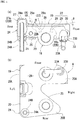
Fig. 1 shows a heater, in which (a) is a partially cutaway left side view, and (b) is a bottom view. -
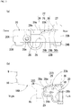
Fig. 2 shows a heat emitting case, in which (a) is a plan view, and (b) is a left side view. -
Fig. 3 shows the heat emitting case, in which (a) is a right side view, and (b) is a cross-sectional view taken along line Z-Z inFig. 2(a) . -
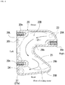
Fig. 4 is a cross-sectional view of the heat emitting case taken along line Y-Y inFig. 2(b) . -
Fig. 5 is a left side view of a heating apparatus-equipped oil separator ASSY. -
Fig. 6 is a rear view of the heating apparatus-equipped oil separator ASSY. -
Fig. 7 is a right side view of the heating apparatus-equipped oil separator ASSY. -
Fig. 8 is a front view of an inline multi-cylinder diesel engine. -
Fig. 9 is a left side view of the engine shown inFig. 8 . -
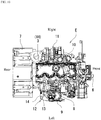
Fig. 10 is a plan view of the engine shown inFig. 8 . - In the following, with reference to the drawings, a description will be given of an embodiment of a blow-by gas heating apparatus of the present invention applied to an industrial inline multi-cylinder diesel engine such as an agricultural tractor engine. Hereinafter, it is defined that, with reference to the direction of a
crankshaft 1K, the side on which aflywheel housing 7 is mounted is rear; the side opposite thereto is front; the side where anintake manifold 8 is mounted is left; and the side where anexhaust manifold 10 is mounted is right. - As shown in
Figs. 8 to 10 , an engine E includes: acylinder head 2 mounted on the upper part of acylinder block 1; a head cover (cylinder head cover) 3 mounted on the upper part of thecylinder head 2; and anoil pan 4 mounted on the lower part of thecylinder block 1. Atransmission case 5 is mounted on the front end of thecylinder block 1. Acooling fan shaft 6 including an engine cooling fan (not shown) is disposed at the front part of thetransmission case 5. A flywheel housing 7 housing a flywheel is disposed at the rear part of thecylinder block 1. - The upper half part of the
cylinder block 1 forms acylinder portion 1A, and the lower half part of thecylinder block 1 forms acrankcase 1B. The crankshaft is denoted by 1K. On the left side of thecylinder head 2, anintake manifold 8 and anoil separator 9 are disposed. On the right side of thecylinder head 2, anexhaust manifold 10, asupercharger 11 and the like are disposed. The engine E is equipped with a blow-bygas return apparatus 12 that returns blow-by gas generated in thecrankcase 1B to an intake passage Q. Note that, thecylinder block 1, thecylinder head 2, and thehead cover 3 are collectively referred to as anengine body 1H. - As shown in
Fig. 5 , the engine E is equipped with the blow-bygas return apparatus 12 that removes any oil component from blow-by gas generated in thecrankcase 1B and thereafter returns the blow-by gas to the intake passage Q. The intake passage Q may be the intake manifold 8 (or its main tube), thesupercharger 11 and the like. The blow-bygas return apparatus 12 includes theoil separator 9 that traps and removes oil from blow-by gas, and a blow-by gas heating apparatus A capable of heating (warming) theoil separator 9. That is, blow-by gas from which oil (any liquid component) is mostly removed by theoil separator 9 is returned to the intake passage Q through adownstream pipe 14 on the returning side. - As shown in
Figs. 5 to 7 , theoil separator 9 includes a separator case having a blow-bygas inlet part 9a communicating with thehead cover 3 via anupstream pipe 13, a blow-bygas outlet 9b communicating with the intake passage Q via thedownstream pipe 14, and anoil outlet 9c for discharging oil (engine oil) trapped and collected from blow-by gas. The separator case houses at least a filter (not shown) capable of trapping and removing any liquid component from blow-by gas. To theoil outlet 9c, anoil return passage 15 formed by a pipe or the like is connected so as to establish communication, so that the oil collected by the oil separator is returned to the inside of thecrankcase 1B by gravity. - The separator case is circular as seen in a vertical direction. As shown in
Fig. 3(b) , at a case bottom 16 of the separator case, the pipe-like oil outlet 9c is disposed at the center as seen in a vertical direction to project downward. The case bottom 16 has acenter projection 17 provided with theoil outlet 9c at its center and projecting downward, and an inclined bottomperipheral wall 18 around thecenter projection 17. The inclined bottomperipheral wall 18 is inclined so that the height of the lower surface rises from the central part toward the peripheral part. That is, the case bottom 16 is formed as a stepped bowl-like bottom peripheral wall about theoil outlet 9c. The case bottom 16 has an inner bottom surface (not shown) which becomes lower toward theoil outlet 9c disposed at the center surrounded by the front, rear, right and left sides. - That is, oil (specifically, any liquid component including oil and water) collected inside the separator case shifts downward in the separator case and flows on the inner bottom surface (not shown), which is the inner surface of the case bottom 16, toward the
oil outlet 9c. - Accordingly, in an extremely low temperature condition, the
oil separator 9 tends to freeze starting from the case bottom 16 where moisture gathers. - Next, a description will be given of a blow-by gas heating apparatus A. As shown in
Figs. 1 ,5 to 7 , the blow-by gas heating apparatus A has a heater (exemplary heat emitting structure) 19 closely abutting onto abottom surface 16A of theoil separator 9. Theheater 19 has aheat emitting case 20 including therein apassage 21 for engine cooling water, aninlet pipe 23A for cooling water attached to theheat emitting case 20, and anoutlet pipe 24A. Theheat emitting case 20 includes aceiling wall 22 that is in surface-contact from below with thebottom surface 16A of theoil separator 9. - As shown in
Figs. 1 to 4 , theheat emitting case 20 is formed to be a box made of metal (e.g., aluminum alloy) having theceiling wall 22 including anupper surface 22A conforming to the shape of thebottom surface 16A of theoil separator 9, ahorizontal bottom wall 26, and thepassage 21 for cooling water which is the inner space of the case. Theheat emitting case 20 is set to have a branched shape (a C-shape, an inverted C-shape) as seen in a vertical direction, with alateral clearance recess 25 for avoiding interference with thedownward oil outlet 9c of theoil separator 9. At the right front end of the heat emitting case 20 (one end in the circumferential direction as seen in a vertical direction), aninlet part 23 for cooling water is provided. At the left rear end of the heat emitting case 20 (other end in the circumferential direction as seen in a vertical direction), anoutlet part 24 is provided. - The
inlet part 23 includes an L-shapedinlet pipe 23A opening at the bottom surface of thepassage 21, and aninlet supporting part 23B for attaching theinlet pipe 23A to thebottom wall 26. The tip of theinlet pipe 23A is led in the left direction, so as to avoid interference between theinlet pipe 23A including any pipe connected to theinlet pipe 23A and theoil outlet 9c. For example, to theinlet pipe 23A, the return route for cooling water having passed through thecylinder head 2 and the like is connected so as to establish communication. - As shown in
Fig. 4 , the cooling water in thepassage 21 flows from theinlet part 23 toward theoutlet part 24, along the S-shaped route formed by a circumferential route and an inverted curved route. - The
outlet part 24 includes alinear outlet pipe 24A extending downward, and anoutlet supporting part 24B for supporting and fixing theoutlet pipe 24A to thebottom wall 26. In theceiling wall 22 corresponding to theoutlet pipe 24A as seen in a vertical direction, thepassage 21 at that corresponding portion forms anupper projection 27 projecting upward, and anupper edge 24a of theoutlet pipe 24A is provided at a position higher than theceiling wall 22 excluding theupper projection 27. For example, to theoutlet pipe 24A, the pipe for cooling water flowing toward the returning port of a radiator is connected so as to establish communication. - As shown in
Figs. 1 to 3 , theceiling wall 22 of theheat emitting case 20 has a centralupper wall part 28 which is the basal site of theclearance recess 25 where theoil outlet 9c is disposed and which is inclined sharply by an angle α (e.g., 45 degrees), a mainupper wall part 29 continuous to the outer peripheral side of the centralupper wall part 28 and inclined mildly by an angle of β (e.g., 7 to 8 degrees), and a horizontal outerupper wall part 30 continuous to the outer peripheral side of the mainupper wall part 29. - An
upper surface 28a of the centralupper wall part 28 and anupper surface 29a of the mainupper wall part 29 structure theupper surface 22A capable of being closely in surface-contact with thebottom surface 16A of theoil separator 9. - An
inner surface 22B of theceiling wall 22 which is the ceiling surface of thepassage 21 is formed by alower surface 28b of the centralupper wall part 28, alower surface 29b of the mainupper wall part 29, and alower surface 30b of the outerupper wall part 30. That is, the height of theinner surface 22B of theceiling wall 22 increases from the central part toward the peripheral part of theheat emitting case 20 as seen in a vertical direction. The height of theinner surface 22B is set to be highest at theoutlet part 24 for the cooling water, that is, at theupper projection 27. - As shown in
Fig. 1 , theupper edge 24a of theoutlet pipe 24A is set at a position second highest to thelower surface 27a of theupper projection 27, whichlower surface 27a is the site of theoutlet part 24 in theinner surface 22B of theceiling wall 22. These elements in theinner surface 22B of theceiling wall 22 are in the following descending order of height: thelower surface 27a of theupper projection 27 > theupper edge 24a of theoutlet pipe 24A > thelower surface 30b of the outerupper wall part 30 > thelower surface 29b of the mainupper wall part 29 > thelower surface 28b of the centralupper wall part 28. - The operation and effect of the blow-by gas heating apparatus A are as follows. The
ceiling wall 22 of theheat emitting case 20 and theoil separator 9 are in surface-contact with each other, over a large area between a group including theupper surface 28a of the centralupper wall part 28 and theupper surface 29a of the mainupper wall part 29, and other group including thecenter projection 17 and the inclined bottomperipheral wall 18. Thus, heat generated by theheater 19 is efficiently transferred to theoil separator 9 from theheat emitting case 20. - Heat is transferred to the case bottom 16 where water gathers, whereby the frozen portion quickly thaws and its temperature rises. Further, by virtue of heat being transferred upward, the
entire oil separator 9 is efficiently warmed. - The
heater 19 is configured to generate heat by allowing cooling water, which is warmed by the engine being started, to pass through theheat emitting case 20. That is, theheater 19 is implemented by effectively using an existing engine element. Therefore, the present embodiment can dispense with any dedicated heat source, and provides the blow-by gas heating apparatus A capable of heating blow-by gas by cost-effective and space-saving reasonable means. - The
passage 21 is formed C-shaped, having theinlet part 23 and theoutlet part 24 disposed at its opposite ends. Therefore, cooling water which is the heat source smoothly flows from theinlet part 23 to theoutlet part 24, and the heat is efficiently transferred to theheat emitting case 20. Provided that air that adversely affects heat transfer enters theheat emitting case 20, the air is carried by the cooling water to theoutlet part 24 and discharged. Additionally, theinner surface 22B of theceiling wall 22 becoming higher outward is advantageous in that, air shifts toward the outer peripheral side while flowing in thepassage 21, and is easily and thoroughly discharged from theoutlet pipe 24A whoseupper edge 24a is at the highest position and positioned on the outer side in the radial direction than the bottom surface (the case bottom 16) of theoil separator 9. It goes without saying that theupper projection 27 is also positioned on the outer side in the radial direction thanoil separator 9. - By virtue of the
heat emitting case 20 including theclearance recess 25 which is not continuous around theoil outlet 9c, thepassage 21 forms a single-system route, realizing smooth flow of cooling water. Additionally, in the state where any pipe is connected to theoil outlet 9c, shifting laterally in theclearance recess 25 direction advantageously allows theheater 19 to be attached to or removed from theoil separator 9. Further, theclearance recess 25 allows theheater 19 to be supported by theengine body 1H while avoiding interference with any projection of theengine body 1H and any other disposed components. - Next, a description will be given of the integration structure between the
oil separator 9 and the blow-by gas heating apparatus A, and the attachment structure to theengine body 1H. - As shown in
Figs. 5 to 7 , theoil separator 9 and theheater 19 are integrated to each other using afirst coupling member 31 screwed across respective right surfaces of theoil separator 9 and theheater 19, and asecond coupling member 32 screwed across respective left surfaces of theoil separator 9 and theheater 19. - As shown in
Fig. 5 , thefirst coupling member 31 is formed of a quadrangular steel plate, and screwed to the right surface of theoil separator 9 with twobolts 33, and to theleft surface 20L of theheat emitting case 20 with twobolts 33.Nut parts 20n for thebolts 33 at theheat emitting case 20 are formed to extend in thepassage 21. - The upper two
bolts 33 for attaching thefirst coupling member 31 join thefirst coupling member 31 and supportinghardware 34 formed of a steel plate. Theupstream pipe 13 is supported by afastening band 36 at a rear upward extendingpiece 34a of the supportinghardware 34. The supportinghardware 34 is configured to function as a supporting component for other engine accessories. - As shown in
Figs. 5 to 7 , thesecond coupling member 32 formed of a steel plate having a greater thickness than thefirst coupling member 31 is fixed with thebolts 33 at two locations in the left surface of theoil separator 9, and fixed with thebolt 33 at onenut part 20n formed at the right surface of an inlet-side extending part 20A (seeFig. 4 ) of theheat emitting case 20. The right side of an outlet-side extending part 20B (seeFig. 4 ) of theheat emitting case 20 is left free. - Mounting
holes 32a are formed at one location in a bentupper end 32A of thesecond coupling member 32, and two locations in a foldedlower end 32B. Bolts 35 (seeFigs. 7 ,9 ) inserted to these three mountingholes 32a attach and fix thesecond coupling member 32 to the left surface of theengine body 1H. Further, threenut parts 32b formed at lower end of thesecond coupling member 32 are configured to be capable of attaching also other engine accessories. - The
heat emitting case 20 may be formed to annularly continuously surround theoil outlet 9c. Alternatively, theheat emitting case 20 may be formed across the lateral surfaces on the front, rear, right, and left side of the oil separator 9 (to have a U-shaped cross section). -
- 9:
- Oil separator
- 9c:
- Oil outlet
- 16A:
- Bottom surface
- 19:
- Heater (Heat emitting structure)
- 20:
- Heat emitting case
- 21:
- Passage for engine cooling water
- 22:
- Ceiling wall
- 22B:
- Inner surface
- 23:
- Inlet part
- 24:
- Outlet part
- 24A:
- Outlet pipe
- 24a:
- Upper edge of outlet pipe
- 25:
- Clearance recess
- 27a:
- Site of outlet part in inner surface
- A:
- Blow-by gas heating apparatus
Claims (5)
- A blow-by gas heating apparatus comprising
a heat emitting structure abutted onto an oil separator configured to trap and remove oil from blow-by gas, wherein
the heat emitting structure has a heat emitting case including inside a passage for engine cooling water, and
the heat emitting case includes a ceiling wall being in surface-contact from below with a bottom surface of the oil separator. - The blow-by gas heating apparatus according to claim 1, wherein a height of an inner surface of the ceiling wall is configured to increase from a central part toward a peripheral part of the heat emitting case as seen in a vertical direction.
- The blow-by gas heating apparatus according to claim 2, wherein the height of the inner surface of the ceiling wall is set to be highest at an outlet part for cooling water.
- The blow-by gas heating apparatus according to claim 3, wherein
the outlet part has an outlet pipe led below the heat emitting case, and
an upper edge of the outlet pipe is set at a position second highest to a site of the outlet part in the inner surface of the ceiling wall. - The blow-by gas heating apparatus according to one of claims 3 and 4, wherein
the heat emitting case is set to be branched shaped as seen in a vertical direction, with a lateral clearance recess for avoiding a downward-oriented oil outlet of the oil separator, and
at one end and other end of the heat emitting case in a circumferential direction as seen in a vertical direction, a cooling water inlet part and the outlet part are respectively provided.
Applications Claiming Priority (2)
| Application Number | Priority Date | Filing Date | Title |
|---|---|---|---|
| JP2016171699A JP6678543B2 (en) | 2016-09-02 | 2016-09-02 | Blow-by gas heating device |
| PCT/JP2017/031326 WO2018043635A1 (en) | 2016-09-02 | 2017-08-31 | Blow-by gas heating device |
Publications (3)
| Publication Number | Publication Date |
|---|---|
| EP3444454A1 true EP3444454A1 (en) | 2019-02-20 |
| EP3444454A4 EP3444454A4 (en) | 2019-12-18 |
| EP3444454B1 EP3444454B1 (en) | 2022-02-23 |
Family
ID=61301038
Family Applications (1)
| Application Number | Title | Priority Date | Filing Date |
|---|---|---|---|
| EP17846639.7A Active EP3444454B1 (en) | 2016-09-02 | 2017-08-31 | Blow-by gas heating device |
Country Status (4)
| Country | Link |
|---|---|
| US (1) | US10704434B2 (en) |
| EP (1) | EP3444454B1 (en) |
| JP (1) | JP6678543B2 (en) |
| WO (1) | WO2018043635A1 (en) |
Families Citing this family (5)
| Publication number | Priority date | Publication date | Assignee | Title |
|---|---|---|---|---|
| JP2021017845A (en) * | 2019-07-19 | 2021-02-15 | いすゞ自動車株式会社 | Blow-by gas treatment device |
| CN111636948A (en) * | 2020-04-30 | 2020-09-08 | 中国第一汽车股份有限公司 | Crankcase heating system and control method thereof |
| US12497912B2 (en) | 2023-01-03 | 2025-12-16 | Caterpillar Inc. | Crankcase oil separator for internal combustion engine |
| US12359593B2 (en) | 2023-01-03 | 2025-07-15 | Caterpillar Inc. | Modular assemblies for crankcase oil separators |
| US11946397B1 (en) * | 2023-05-01 | 2024-04-02 | Caterpillar Inc. | Pre-heated crankcase ventilation system architecture |
Family Cites Families (11)
| Publication number | Priority date | Publication date | Assignee | Title |
|---|---|---|---|---|
| DE19736039B4 (en) * | 1997-08-20 | 2018-01-11 | Man Truck & Bus Ag | Internal combustion engine with an oil module |
| JP3423649B2 (en) * | 1999-09-03 | 2003-07-07 | 本田技研工業株式会社 | Breather chamber structure of internal combustion engine |
| JP2006299932A (en) | 2005-04-20 | 2006-11-02 | Toyota Motor Corp | Heat exchange structure of blow-by gas reduction device |
| JP2007247552A (en) | 2006-03-16 | 2007-09-27 | Hino Motors Ltd | Ventilator equipment |
| JP4162020B2 (en) * | 2006-07-18 | 2008-10-08 | トヨタ自動車株式会社 | Oil recovery structure of blow-by gas reduction device |
| US7942122B2 (en) * | 2006-12-01 | 2011-05-17 | Toyota Motor Engineering & Manufacturing North America, Inc. | Engine head cover assembly having an integrated oil separator and a removable cover |
| FR2913249B1 (en) | 2007-03-01 | 2012-03-16 | Peugeot Citroen Automobiles Sa | METHOD AND DEVICE FOR REHAUTING CARTER GAS AND DECANTATION CHAMBER FOR CARTER GAS |
| JP6162461B2 (en) | 2013-04-17 | 2017-07-12 | 日野自動車株式会社 | Closed breather system |
| EP2865934B1 (en) * | 2013-10-28 | 2016-04-06 | Aisin Seiki Kabushiki Kaisha | Internal combustion engine and separator structure thereof |
| JP6299298B2 (en) * | 2013-11-07 | 2018-03-28 | アイシン精機株式会社 | Internal combustion engine and internal combustion engine separator structure |
| DE102013021983B4 (en) * | 2013-12-20 | 2016-03-24 | Mtu Friedrichshafen Gmbh | A method for improving the cold start property of an internal combustion engine and crankcase ventilation device thereto |
-
2016
- 2016-09-02 JP JP2016171699A patent/JP6678543B2/en active Active
-
2017
- 2017-08-31 WO PCT/JP2017/031326 patent/WO2018043635A1/en not_active Ceased
- 2017-08-31 US US16/305,932 patent/US10704434B2/en active Active
- 2017-08-31 EP EP17846639.7A patent/EP3444454B1/en active Active
Also Published As
| Publication number | Publication date |
|---|---|
| JP2018035786A (en) | 2018-03-08 |
| WO2018043635A1 (en) | 2018-03-08 |
| EP3444454A4 (en) | 2019-12-18 |
| EP3444454B1 (en) | 2022-02-23 |
| JP6678543B2 (en) | 2020-04-08 |
| US20190218947A1 (en) | 2019-07-18 |
| US10704434B2 (en) | 2020-07-07 |
Similar Documents
| Publication | Publication Date | Title |
|---|---|---|
| EP3444454B1 (en) | Blow-by gas heating device | |
| US6058898A (en) | Structural oil pan with integrated oil filtration and cooling system | |
| US8997487B2 (en) | Turbocharger | |
| US10371026B2 (en) | Blow-by gas return structure | |
| JP6660854B2 (en) | Oil separator exterior engine | |
| US20110146638A1 (en) | Blow-by gas recirculation system | |
| US20150322843A1 (en) | Air flow guide for an internal combustion engine | |
| EP2853726B1 (en) | Engine | |
| JP2015010495A (en) | Exhaust gas recirculation device for vehicle engine | |
| JP5665701B2 (en) | Water droplet separator contamination prevention structure for cleaning air and ship equipped with the same | |
| JP2015124692A (en) | Internal combustion engine | |
| JP6782200B2 (en) | Blow-by gas reflux device | |
| JP7343580B2 (en) | Blow-by gas recirculation device | |
| JP7103928B2 (en) | Blow-by gas recirculation device | |
| US11359526B2 (en) | Blowby gas discharging device | |
| JP7206945B2 (en) | internal combustion engine for vehicle | |
| US20180179927A1 (en) | Engine | |
| JP2015068190A (en) | Intake manifold structure for vehicle engine | |
| EP3517769B1 (en) | Engine intake and exhaust system and internal combustion engine | |
| RU2439355C2 (en) | Internal combustion engine with liquid cooling | |
| EP4253750A1 (en) | Egr device for internal combustion engine | |
| EP4253751B1 (en) | Egr device for internal combustion engine | |
| JP2016125452A (en) | Internal combustion engine | |
| JP7081976B2 (en) | Engine with blow-by gas recirculation device | |
| JP2020180606A (en) | Engine for vehicle |
Legal Events
| Date | Code | Title | Description |
|---|---|---|---|
| STAA | Information on the status of an ep patent application or granted ep patent |
Free format text: STATUS: THE INTERNATIONAL PUBLICATION HAS BEEN MADE |
|
| PUAI | Public reference made under article 153(3) epc to a published international application that has entered the european phase |
Free format text: ORIGINAL CODE: 0009012 |
|
| STAA | Information on the status of an ep patent application or granted ep patent |
Free format text: STATUS: REQUEST FOR EXAMINATION WAS MADE |
|
| 17P | Request for examination filed |
Effective date: 20181115 |
|
| AK | Designated contracting states |
Kind code of ref document: A1 Designated state(s): AL AT BE BG CH CY CZ DE DK EE ES FI FR GB GR HR HU IE IS IT LI LT LU LV MC MK MT NL NO PL PT RO RS SE SI SK SM TR |
|
| AX | Request for extension of the european patent |
Extension state: BA ME |
|
| DAV | Request for validation of the european patent (deleted) | ||
| DAX | Request for extension of the european patent (deleted) | ||
| A4 | Supplementary search report drawn up and despatched |
Effective date: 20191120 |
|
| RIC1 | Information provided on ipc code assigned before grant |
Ipc: F01M 5/00 20060101ALI20191114BHEP Ipc: F01M 13/04 20060101ALI20191114BHEP Ipc: F01M 13/00 20060101AFI20191114BHEP |
|
| GRAP | Despatch of communication of intention to grant a patent |
Free format text: ORIGINAL CODE: EPIDOSNIGR1 |
|
| STAA | Information on the status of an ep patent application or granted ep patent |
Free format text: STATUS: GRANT OF PATENT IS INTENDED |
|
| GRAJ | Information related to disapproval of communication of intention to grant by the applicant or resumption of examination proceedings by the epo deleted |
Free format text: ORIGINAL CODE: EPIDOSDIGR1 |
|
| STAA | Information on the status of an ep patent application or granted ep patent |
Free format text: STATUS: REQUEST FOR EXAMINATION WAS MADE |
|
| GRAP | Despatch of communication of intention to grant a patent |
Free format text: ORIGINAL CODE: EPIDOSNIGR1 |
|
| STAA | Information on the status of an ep patent application or granted ep patent |
Free format text: STATUS: GRANT OF PATENT IS INTENDED |
|
| INTG | Intention to grant announced |
Effective date: 20211014 |
|
| INTC | Intention to grant announced (deleted) | ||
| INTG | Intention to grant announced |
Effective date: 20211026 |
|
| GRAS | Grant fee paid |
Free format text: ORIGINAL CODE: EPIDOSNIGR3 |
|
| GRAA | (expected) grant |
Free format text: ORIGINAL CODE: 0009210 |
|
| STAA | Information on the status of an ep patent application or granted ep patent |
Free format text: STATUS: THE PATENT HAS BEEN GRANTED |
|
| AK | Designated contracting states |
Kind code of ref document: B1 Designated state(s): AL AT BE BG CH CY CZ DE DK EE ES FI FR GB GR HR HU IE IS IT LI LT LU LV MC MK MT NL NO PL PT RO RS SE SI SK SM TR |
|
| REG | Reference to a national code |
Ref country code: GB Ref legal event code: FG4D |
|
| REG | Reference to a national code |
Ref country code: CH Ref legal event code: EP |
|
| REG | Reference to a national code |
Ref country code: AT Ref legal event code: REF Ref document number: 1470622 Country of ref document: AT Kind code of ref document: T Effective date: 20220315 |
|
| REG | Reference to a national code |
Ref country code: IE Ref legal event code: FG4D |
|
| REG | Reference to a national code |
Ref country code: DE Ref legal event code: R096 Ref document number: 602017053827 Country of ref document: DE |
|
| REG | Reference to a national code |
Ref country code: LT Ref legal event code: MG9D |
|
| REG | Reference to a national code |
Ref country code: NL Ref legal event code: MP Effective date: 20220223 |
|
| REG | Reference to a national code |
Ref country code: AT Ref legal event code: MK05 Ref document number: 1470622 Country of ref document: AT Kind code of ref document: T Effective date: 20220223 |
|
| PG25 | Lapsed in a contracting state [announced via postgrant information from national office to epo] |
Ref country code: SE Free format text: LAPSE BECAUSE OF FAILURE TO SUBMIT A TRANSLATION OF THE DESCRIPTION OR TO PAY THE FEE WITHIN THE PRESCRIBED TIME-LIMIT Effective date: 20220223 Ref country code: RS Free format text: LAPSE BECAUSE OF FAILURE TO SUBMIT A TRANSLATION OF THE DESCRIPTION OR TO PAY THE FEE WITHIN THE PRESCRIBED TIME-LIMIT Effective date: 20220223 Ref country code: PT Free format text: LAPSE BECAUSE OF FAILURE TO SUBMIT A TRANSLATION OF THE DESCRIPTION OR TO PAY THE FEE WITHIN THE PRESCRIBED TIME-LIMIT Effective date: 20220623 Ref country code: NO Free format text: LAPSE BECAUSE OF FAILURE TO SUBMIT A TRANSLATION OF THE DESCRIPTION OR TO PAY THE FEE WITHIN THE PRESCRIBED TIME-LIMIT Effective date: 20220523 Ref country code: NL Free format text: LAPSE BECAUSE OF FAILURE TO SUBMIT A TRANSLATION OF THE DESCRIPTION OR TO PAY THE FEE WITHIN THE PRESCRIBED TIME-LIMIT Effective date: 20220223 Ref country code: LT Free format text: LAPSE BECAUSE OF FAILURE TO SUBMIT A TRANSLATION OF THE DESCRIPTION OR TO PAY THE FEE WITHIN THE PRESCRIBED TIME-LIMIT Effective date: 20220223 Ref country code: HR Free format text: LAPSE BECAUSE OF FAILURE TO SUBMIT A TRANSLATION OF THE DESCRIPTION OR TO PAY THE FEE WITHIN THE PRESCRIBED TIME-LIMIT Effective date: 20220223 Ref country code: ES Free format text: LAPSE BECAUSE OF FAILURE TO SUBMIT A TRANSLATION OF THE DESCRIPTION OR TO PAY THE FEE WITHIN THE PRESCRIBED TIME-LIMIT Effective date: 20220223 Ref country code: BG Free format text: LAPSE BECAUSE OF FAILURE TO SUBMIT A TRANSLATION OF THE DESCRIPTION OR TO PAY THE FEE WITHIN THE PRESCRIBED TIME-LIMIT Effective date: 20220523 |
|
| PG25 | Lapsed in a contracting state [announced via postgrant information from national office to epo] |
Ref country code: PL Free format text: LAPSE BECAUSE OF FAILURE TO SUBMIT A TRANSLATION OF THE DESCRIPTION OR TO PAY THE FEE WITHIN THE PRESCRIBED TIME-LIMIT Effective date: 20220223 Ref country code: LV Free format text: LAPSE BECAUSE OF FAILURE TO SUBMIT A TRANSLATION OF THE DESCRIPTION OR TO PAY THE FEE WITHIN THE PRESCRIBED TIME-LIMIT Effective date: 20220223 Ref country code: GR Free format text: LAPSE BECAUSE OF FAILURE TO SUBMIT A TRANSLATION OF THE DESCRIPTION OR TO PAY THE FEE WITHIN THE PRESCRIBED TIME-LIMIT Effective date: 20220524 Ref country code: FI Free format text: LAPSE BECAUSE OF FAILURE TO SUBMIT A TRANSLATION OF THE DESCRIPTION OR TO PAY THE FEE WITHIN THE PRESCRIBED TIME-LIMIT Effective date: 20220223 Ref country code: AT Free format text: LAPSE BECAUSE OF FAILURE TO SUBMIT A TRANSLATION OF THE DESCRIPTION OR TO PAY THE FEE WITHIN THE PRESCRIBED TIME-LIMIT Effective date: 20220223 |
|
| PG25 | Lapsed in a contracting state [announced via postgrant information from national office to epo] |
Ref country code: IS Free format text: LAPSE BECAUSE OF FAILURE TO SUBMIT A TRANSLATION OF THE DESCRIPTION OR TO PAY THE FEE WITHIN THE PRESCRIBED TIME-LIMIT Effective date: 20220623 |
|
| PG25 | Lapsed in a contracting state [announced via postgrant information from national office to epo] |
Ref country code: SM Free format text: LAPSE BECAUSE OF FAILURE TO SUBMIT A TRANSLATION OF THE DESCRIPTION OR TO PAY THE FEE WITHIN THE PRESCRIBED TIME-LIMIT Effective date: 20220223 Ref country code: SK Free format text: LAPSE BECAUSE OF FAILURE TO SUBMIT A TRANSLATION OF THE DESCRIPTION OR TO PAY THE FEE WITHIN THE PRESCRIBED TIME-LIMIT Effective date: 20220223 Ref country code: RO Free format text: LAPSE BECAUSE OF FAILURE TO SUBMIT A TRANSLATION OF THE DESCRIPTION OR TO PAY THE FEE WITHIN THE PRESCRIBED TIME-LIMIT Effective date: 20220223 Ref country code: EE Free format text: LAPSE BECAUSE OF FAILURE TO SUBMIT A TRANSLATION OF THE DESCRIPTION OR TO PAY THE FEE WITHIN THE PRESCRIBED TIME-LIMIT Effective date: 20220223 Ref country code: DK Free format text: LAPSE BECAUSE OF FAILURE TO SUBMIT A TRANSLATION OF THE DESCRIPTION OR TO PAY THE FEE WITHIN THE PRESCRIBED TIME-LIMIT Effective date: 20220223 Ref country code: CZ Free format text: LAPSE BECAUSE OF FAILURE TO SUBMIT A TRANSLATION OF THE DESCRIPTION OR TO PAY THE FEE WITHIN THE PRESCRIBED TIME-LIMIT Effective date: 20220223 |
|
| REG | Reference to a national code |
Ref country code: DE Ref legal event code: R097 Ref document number: 602017053827 Country of ref document: DE |
|
| PG25 | Lapsed in a contracting state [announced via postgrant information from national office to epo] |
Ref country code: AL Free format text: LAPSE BECAUSE OF FAILURE TO SUBMIT A TRANSLATION OF THE DESCRIPTION OR TO PAY THE FEE WITHIN THE PRESCRIBED TIME-LIMIT Effective date: 20220223 |
|
| PLBE | No opposition filed within time limit |
Free format text: ORIGINAL CODE: 0009261 |
|
| STAA | Information on the status of an ep patent application or granted ep patent |
Free format text: STATUS: NO OPPOSITION FILED WITHIN TIME LIMIT |
|
| 26N | No opposition filed |
Effective date: 20221124 |
|
| PG25 | Lapsed in a contracting state [announced via postgrant information from national office to epo] |
Ref country code: SI Free format text: LAPSE BECAUSE OF FAILURE TO SUBMIT A TRANSLATION OF THE DESCRIPTION OR TO PAY THE FEE WITHIN THE PRESCRIBED TIME-LIMIT Effective date: 20220223 |
|
| PG25 | Lapsed in a contracting state [announced via postgrant information from national office to epo] |
Ref country code: MC Free format text: LAPSE BECAUSE OF FAILURE TO SUBMIT A TRANSLATION OF THE DESCRIPTION OR TO PAY THE FEE WITHIN THE PRESCRIBED TIME-LIMIT Effective date: 20220223 |
|
| REG | Reference to a national code |
Ref country code: CH Ref legal event code: PL |
|
| PG25 | Lapsed in a contracting state [announced via postgrant information from national office to epo] |
Ref country code: LU Free format text: LAPSE BECAUSE OF NON-PAYMENT OF DUE FEES Effective date: 20220831 Ref country code: LI Free format text: LAPSE BECAUSE OF NON-PAYMENT OF DUE FEES Effective date: 20220831 Ref country code: CH Free format text: LAPSE BECAUSE OF NON-PAYMENT OF DUE FEES Effective date: 20220831 |
|
| REG | Reference to a national code |
Ref country code: BE Ref legal event code: MM Effective date: 20220831 |
|
| PG25 | Lapsed in a contracting state [announced via postgrant information from national office to epo] |
Ref country code: IT Free format text: LAPSE BECAUSE OF FAILURE TO SUBMIT A TRANSLATION OF THE DESCRIPTION OR TO PAY THE FEE WITHIN THE PRESCRIBED TIME-LIMIT Effective date: 20220223 Ref country code: IE Free format text: LAPSE BECAUSE OF NON-PAYMENT OF DUE FEES Effective date: 20220831 Ref country code: FR Free format text: LAPSE BECAUSE OF NON-PAYMENT OF DUE FEES Effective date: 20220831 |
|
| PG25 | Lapsed in a contracting state [announced via postgrant information from national office to epo] |
Ref country code: BE Free format text: LAPSE BECAUSE OF NON-PAYMENT OF DUE FEES Effective date: 20220831 |
|
| PG25 | Lapsed in a contracting state [announced via postgrant information from national office to epo] |
Ref country code: HU Free format text: LAPSE BECAUSE OF FAILURE TO SUBMIT A TRANSLATION OF THE DESCRIPTION OR TO PAY THE FEE WITHIN THE PRESCRIBED TIME-LIMIT; INVALID AB INITIO Effective date: 20170831 |
|
| PG25 | Lapsed in a contracting state [announced via postgrant information from national office to epo] |
Ref country code: CY Free format text: LAPSE BECAUSE OF FAILURE TO SUBMIT A TRANSLATION OF THE DESCRIPTION OR TO PAY THE FEE WITHIN THE PRESCRIBED TIME-LIMIT Effective date: 20220223 |
|
| PG25 | Lapsed in a contracting state [announced via postgrant information from national office to epo] |
Ref country code: MK Free format text: LAPSE BECAUSE OF FAILURE TO SUBMIT A TRANSLATION OF THE DESCRIPTION OR TO PAY THE FEE WITHIN THE PRESCRIBED TIME-LIMIT Effective date: 20220223 |
|
| PG25 | Lapsed in a contracting state [announced via postgrant information from national office to epo] |
Ref country code: MT Free format text: LAPSE BECAUSE OF FAILURE TO SUBMIT A TRANSLATION OF THE DESCRIPTION OR TO PAY THE FEE WITHIN THE PRESCRIBED TIME-LIMIT Effective date: 20220223 |
|
| PGFP | Annual fee paid to national office [announced via postgrant information from national office to epo] |
Ref country code: DE Payment date: 20250702 Year of fee payment: 9 |
|
| PGFP | Annual fee paid to national office [announced via postgrant information from national office to epo] |
Ref country code: GB Payment date: 20250703 Year of fee payment: 9 |
|
| PG25 | Lapsed in a contracting state [announced via postgrant information from national office to epo] |
Ref country code: TR Free format text: LAPSE BECAUSE OF FAILURE TO SUBMIT A TRANSLATION OF THE DESCRIPTION OR TO PAY THE FEE WITHIN THE PRESCRIBED TIME-LIMIT Effective date: 20220223 |