EP3444383A1 - Positive electrode for alkaline water electrolysis and method for producing positive electrode for alkaline water electrolysis - Google Patents
Positive electrode for alkaline water electrolysis and method for producing positive electrode for alkaline water electrolysis Download PDFInfo
- Publication number
- EP3444383A1 EP3444383A1 EP17782290.5A EP17782290A EP3444383A1 EP 3444383 A1 EP3444383 A1 EP 3444383A1 EP 17782290 A EP17782290 A EP 17782290A EP 3444383 A1 EP3444383 A1 EP 3444383A1
- Authority
- EP
- European Patent Office
- Prior art keywords
- nickel
- anode
- water electrolysis
- alkaline water
- catalyst layer
- Prior art date
- Legal status (The legal status is an assumption and is not a legal conclusion. Google has not performed a legal analysis and makes no representation as to the accuracy of the status listed.)
- Granted
Links
Images

Classifications
-
- C—CHEMISTRY; METALLURGY
- C25—ELECTROLYTIC OR ELECTROPHORETIC PROCESSES; APPARATUS THEREFOR
- C25B—ELECTROLYTIC OR ELECTROPHORETIC PROCESSES FOR THE PRODUCTION OF COMPOUNDS OR NON-METALS; APPARATUS THEREFOR
- C25B11/00—Electrodes; Manufacture thereof not otherwise provided for
- C25B11/04—Electrodes; Manufacture thereof not otherwise provided for characterised by the material
- C25B11/051—Electrodes formed of electrocatalysts on a substrate or carrier
- C25B11/073—Electrodes formed of electrocatalysts on a substrate or carrier characterised by the electrocatalyst material
- C25B11/091—Electrodes formed of electrocatalysts on a substrate or carrier characterised by the electrocatalyst material consisting of at least one catalytic element and at least one catalytic compound; consisting of two or more catalytic elements or catalytic compounds
- C25B11/093—Electrodes formed of electrocatalysts on a substrate or carrier characterised by the electrocatalyst material consisting of at least one catalytic element and at least one catalytic compound; consisting of two or more catalytic elements or catalytic compounds at least one noble metal or noble metal oxide and at least one non-noble metal oxide
-
- C—CHEMISTRY; METALLURGY
- C25—ELECTROLYTIC OR ELECTROPHORETIC PROCESSES; APPARATUS THEREFOR
- C25B—ELECTROLYTIC OR ELECTROPHORETIC PROCESSES FOR THE PRODUCTION OF COMPOUNDS OR NON-METALS; APPARATUS THEREFOR
- C25B11/00—Electrodes; Manufacture thereof not otherwise provided for
- C25B11/04—Electrodes; Manufacture thereof not otherwise provided for characterised by the material
- C25B11/051—Electrodes formed of electrocatalysts on a substrate or carrier
- C25B11/055—Electrodes formed of electrocatalysts on a substrate or carrier characterised by the substrate or carrier material
- C25B11/057—Electrodes formed of electrocatalysts on a substrate or carrier characterised by the substrate or carrier material consisting of a single element or compound
-
- B—PERFORMING OPERATIONS; TRANSPORTING
- B01—PHYSICAL OR CHEMICAL PROCESSES OR APPARATUS IN GENERAL
- B01J—CHEMICAL OR PHYSICAL PROCESSES, e.g. CATALYSIS OR COLLOID CHEMISTRY; THEIR RELEVANT APPARATUS
- B01J23/00—Catalysts comprising metals or metal oxides or hydroxides, not provided for in group B01J21/00
- B01J23/002—Mixed oxides other than spinels, e.g. perovskite
-
- B—PERFORMING OPERATIONS; TRANSPORTING
- B01—PHYSICAL OR CHEMICAL PROCESSES OR APPARATUS IN GENERAL
- B01J—CHEMICAL OR PHYSICAL PROCESSES, e.g. CATALYSIS OR COLLOID CHEMISTRY; THEIR RELEVANT APPARATUS
- B01J23/00—Catalysts comprising metals or metal oxides or hydroxides, not provided for in group B01J21/00
- B01J23/38—Catalysts comprising metals or metal oxides or hydroxides, not provided for in group B01J21/00 of noble metals
- B01J23/40—Catalysts comprising metals or metal oxides or hydroxides, not provided for in group B01J21/00 of noble metals of the platinum group metals
- B01J23/46—Ruthenium, rhodium, osmium or iridium
- B01J23/462—Ruthenium
-
- B—PERFORMING OPERATIONS; TRANSPORTING
- B01—PHYSICAL OR CHEMICAL PROCESSES OR APPARATUS IN GENERAL
- B01J—CHEMICAL OR PHYSICAL PROCESSES, e.g. CATALYSIS OR COLLOID CHEMISTRY; THEIR RELEVANT APPARATUS
- B01J23/00—Catalysts comprising metals or metal oxides or hydroxides, not provided for in group B01J21/00
- B01J23/38—Catalysts comprising metals or metal oxides or hydroxides, not provided for in group B01J21/00 of noble metals
- B01J23/40—Catalysts comprising metals or metal oxides or hydroxides, not provided for in group B01J21/00 of noble metals of the platinum group metals
- B01J23/46—Ruthenium, rhodium, osmium or iridium
- B01J23/468—Iridium
-
- C—CHEMISTRY; METALLURGY
- C25—ELECTROLYTIC OR ELECTROPHORETIC PROCESSES; APPARATUS THEREFOR
- C25B—ELECTROLYTIC OR ELECTROPHORETIC PROCESSES FOR THE PRODUCTION OF COMPOUNDS OR NON-METALS; APPARATUS THEREFOR
- C25B1/00—Electrolytic production of inorganic compounds or non-metals
- C25B1/01—Products
- C25B1/02—Hydrogen or oxygen
- C25B1/04—Hydrogen or oxygen by electrolysis of water
-
- C—CHEMISTRY; METALLURGY
- C25—ELECTROLYTIC OR ELECTROPHORETIC PROCESSES; APPARATUS THEREFOR
- C25B—ELECTROLYTIC OR ELECTROPHORETIC PROCESSES FOR THE PRODUCTION OF COMPOUNDS OR NON-METALS; APPARATUS THEREFOR
- C25B11/00—Electrodes; Manufacture thereof not otherwise provided for
- C25B11/04—Electrodes; Manufacture thereof not otherwise provided for characterised by the material
- C25B11/051—Electrodes formed of electrocatalysts on a substrate or carrier
-
- C—CHEMISTRY; METALLURGY
- C25—ELECTROLYTIC OR ELECTROPHORETIC PROCESSES; APPARATUS THEREFOR
- C25B—ELECTROLYTIC OR ELECTROPHORETIC PROCESSES FOR THE PRODUCTION OF COMPOUNDS OR NON-METALS; APPARATUS THEREFOR
- C25B11/00—Electrodes; Manufacture thereof not otherwise provided for
- C25B11/04—Electrodes; Manufacture thereof not otherwise provided for characterised by the material
- C25B11/051—Electrodes formed of electrocatalysts on a substrate or carrier
- C25B11/052—Electrodes comprising one or more electrocatalytic coatings on a substrate
- C25B11/053—Electrodes comprising one or more electrocatalytic coatings on a substrate characterised by multilayer electrocatalytic coatings
-
- C—CHEMISTRY; METALLURGY
- C25—ELECTROLYTIC OR ELECTROPHORETIC PROCESSES; APPARATUS THEREFOR
- C25B—ELECTROLYTIC OR ELECTROPHORETIC PROCESSES FOR THE PRODUCTION OF COMPOUNDS OR NON-METALS; APPARATUS THEREFOR
- C25B11/00—Electrodes; Manufacture thereof not otherwise provided for
- C25B11/04—Electrodes; Manufacture thereof not otherwise provided for characterised by the material
- C25B11/051—Electrodes formed of electrocatalysts on a substrate or carrier
- C25B11/055—Electrodes formed of electrocatalysts on a substrate or carrier characterised by the substrate or carrier material
- C25B11/057—Electrodes formed of electrocatalysts on a substrate or carrier characterised by the substrate or carrier material consisting of a single element or compound
- C25B11/067—Inorganic compound e.g. ITO, silica or titania
-
- C—CHEMISTRY; METALLURGY
- C25—ELECTROLYTIC OR ELECTROPHORETIC PROCESSES; APPARATUS THEREFOR
- C25B—ELECTROLYTIC OR ELECTROPHORETIC PROCESSES FOR THE PRODUCTION OF COMPOUNDS OR NON-METALS; APPARATUS THEREFOR
- C25B9/00—Cells or assemblies of cells; Constructional parts of cells; Assemblies of constructional parts, e.g. electrode-diaphragm assemblies; Process-related cell features
-
- C—CHEMISTRY; METALLURGY
- C25—ELECTROLYTIC OR ELECTROPHORETIC PROCESSES; APPARATUS THEREFOR
- C25B—ELECTROLYTIC OR ELECTROPHORETIC PROCESSES FOR THE PRODUCTION OF COMPOUNDS OR NON-METALS; APPARATUS THEREFOR
- C25B9/00—Cells or assemblies of cells; Constructional parts of cells; Assemblies of constructional parts, e.g. electrode-diaphragm assemblies; Process-related cell features
- C25B9/70—Assemblies comprising two or more cells
- C25B9/73—Assemblies comprising two or more cells of the filter-press type
-
- B—PERFORMING OPERATIONS; TRANSPORTING
- B01—PHYSICAL OR CHEMICAL PROCESSES OR APPARATUS IN GENERAL
- B01J—CHEMICAL OR PHYSICAL PROCESSES, e.g. CATALYSIS OR COLLOID CHEMISTRY; THEIR RELEVANT APPARATUS
- B01J2523/00—Constitutive chemical elements of heterogeneous catalysts
- B01J2523/30—Constitutive chemical elements of heterogeneous catalysts of Group III (IIIA or IIIB) of the Periodic Table
- B01J2523/37—Lanthanides
-
- B—PERFORMING OPERATIONS; TRANSPORTING
- B01—PHYSICAL OR CHEMICAL PROCESSES OR APPARATUS IN GENERAL
- B01J—CHEMICAL OR PHYSICAL PROCESSES, e.g. CATALYSIS OR COLLOID CHEMISTRY; THEIR RELEVANT APPARATUS
- B01J2523/00—Constitutive chemical elements of heterogeneous catalysts
- B01J2523/80—Constitutive chemical elements of heterogeneous catalysts of Group VIII of the Periodic Table
- B01J2523/84—Metals of the iron group
- B01J2523/845—Cobalt
-
- B—PERFORMING OPERATIONS; TRANSPORTING
- B01—PHYSICAL OR CHEMICAL PROCESSES OR APPARATUS IN GENERAL
- B01J—CHEMICAL OR PHYSICAL PROCESSES, e.g. CATALYSIS OR COLLOID CHEMISTRY; THEIR RELEVANT APPARATUS
- B01J2523/00—Constitutive chemical elements of heterogeneous catalysts
- B01J2523/80—Constitutive chemical elements of heterogeneous catalysts of Group VIII of the Periodic Table
- B01J2523/84—Metals of the iron group
- B01J2523/847—Nickel
-
- C—CHEMISTRY; METALLURGY
- C01—INORGANIC CHEMISTRY
- C01P—INDEXING SCHEME RELATING TO STRUCTURAL AND PHYSICAL ASPECTS OF SOLID INORGANIC COMPOUNDS
- C01P2002/00—Crystal-structural characteristics
- C01P2002/30—Three-dimensional structures
- C01P2002/36—Three-dimensional structures pyrochlore-type (A2B2O7)
-
- Y—GENERAL TAGGING OF NEW TECHNOLOGICAL DEVELOPMENTS; GENERAL TAGGING OF CROSS-SECTIONAL TECHNOLOGIES SPANNING OVER SEVERAL SECTIONS OF THE IPC; TECHNICAL SUBJECTS COVERED BY FORMER USPC CROSS-REFERENCE ART COLLECTIONS [XRACs] AND DIGESTS
- Y02—TECHNOLOGIES OR APPLICATIONS FOR MITIGATION OR ADAPTATION AGAINST CLIMATE CHANGE
- Y02E—REDUCTION OF GREENHOUSE GAS [GHG] EMISSIONS, RELATED TO ENERGY GENERATION, TRANSMISSION OR DISTRIBUTION
- Y02E60/00—Enabling technologies; Technologies with a potential or indirect contribution to GHG emissions mitigation
- Y02E60/30—Hydrogen technology
- Y02E60/36—Hydrogen production from non-carbon containing sources, e.g. by water electrolysis
-
- Y—GENERAL TAGGING OF NEW TECHNOLOGICAL DEVELOPMENTS; GENERAL TAGGING OF CROSS-SECTIONAL TECHNOLOGIES SPANNING OVER SEVERAL SECTIONS OF THE IPC; TECHNICAL SUBJECTS COVERED BY FORMER USPC CROSS-REFERENCE ART COLLECTIONS [XRACs] AND DIGESTS
- Y02—TECHNOLOGIES OR APPLICATIONS FOR MITIGATION OR ADAPTATION AGAINST CLIMATE CHANGE
- Y02P—CLIMATE CHANGE MITIGATION TECHNOLOGIES IN THE PRODUCTION OR PROCESSING OF GOODS
- Y02P20/00—Technologies relating to chemical industry
- Y02P20/10—Process efficiency
- Y02P20/133—Renewable energy sources, e.g. sunlight
Definitions
- the present invention relates to an anode used in alkaline water electrolysis, and relates particularly to an anode for alkaline water electrolysis that requires a low cell voltage and a method for producing the anode.
- Hydrogen is a secondary energy source that is suitable for storage and transport, and has little environmental impact. As a result, hydrogen energy systems that use hydrogen as an energy carrier are attracting much interest. Currently, hydrogen is mainly produced by steam reforming of fossil fuels or the like. From the viewpoints of problems such as global warming and fossil fuel depletion, the importance of alkaline water electrolysis which uses renewable energy such as solar cells, wind power or hydroelectric power as a power source continues to increase.
- Water electrolysis can be broadly classified into two types.
- One type is alkaline water electrolysis, which uses a high-concentration alkaline aqueous solution as the electrolyte.
- the other type is solid polymer water electrolysis, which uses a diamond electrode and uses a solid polymer electrolyte (SPE) as the electrolyte.
- SPE solid polymer electrolyte
- the electrode reactions at the two electrodes are as follows.
- High-concentration alkaline aqueous solutions increase in conductivity as the temperature increases, but the corrosiveness also increases. Accordingly, the upper limit for the operating temperature is suppressed to about 80 to 90°C.
- the development of electrolyzer structural materials and various piping materials that are capable of withstanding higher temperatures and high-concentration alkaline aqueous solutions, and the development of low-resistance diaphragms and electrodes having increased surface area and provided with a catalyst have enabled electrolysis performance to be improved to about 1.7 to 1.9 V at a current density of 0.3 to 0.4 Acm -2 (efficiency: 78 to 87%).
- Ni-based electrode typically uses a nickel-based material that is stable in the high-concentration alkaline aqueous solution, and it has been reported that a Ni-based electrode has a lifespan of several decades or longer in alkaline water electrolysis that uses a stable power source (Non-Patent Documents 1 and 2). However, Ni electrodes have a high overpotential, and suffer from poor productivity.
- Patent Document 1 porous nickel or Ni or an alloy thereof has been used as the substrate of the anode for oxygen generation used in alkaline water electrolysis.
- the following types of metals or metal oxides have conventionally been used as the electrode catalyst layer of the anode for oxygen generation used in alkaline water electrolysis.
- Objects of the present invention are to provide an anode for alkaline water electrolysis that has a low cell voltage while retaining good corrosion resistance, and to provide a method for producing such an anode.
- One aspect in the present invention is an anode for alkaline water electrolysis containing a conductive substrate having at least a surface composed of nickel or a nickel-based alloy, and an electrode catalyst layer formed on the surface of the conductive substrate, wherein a catalyst component that constitutes the electrode catalyst layer contains a first catalyst component having either a nickel-cobalt spinel oxide represented by a structural formula NiCo 2 O 4 , or a lanthanide-nickel-cobalt perovskite oxide represented by a structural formula XNi a Co 1-a O 3 (wherein X represents at least one metal selected from among the lanthanides including lanthanum, cerium and praseodymium, and 0 ⁇ a ⁇ 1), and a second catalyst component having at least one of iridium oxide and ruthenium oxide.
- a catalyst component that constitutes the electrode catalyst layer contains a first catalyst component having either a nickel-cobalt spinel oxide represented by a structural formula NiCo 2 O 4 , or a lanthanide
- the structural formula of the lanthanide-nickel-cobalt perovskite oxide is preferably XNi 0.2 Co 0.8 O 3 .
- the lanthanide is lanthanum
- the lanthanide-nickel-cobalt perovskite oxide is a lanthanum-nickel-cobalt perovskite oxide.
- the electrode catalyst layer is preferably formed using a mixture of the first catalyst component and the second catalyst component.
- the electrode catalyst layer is preferably composed of an electrode catalyst layer with a stacked structure in which a first catalyst layer formed from the first catalyst component and a second catalyst layer formed from the second catalyst component are stacked.
- the first catalyst layer is formed on the surface of the conductive substrate, and the second catalyst layer is formed on the surface of the first catalyst layer.
- the amount of the second catalyst component calculated as an amount of the component metal, is preferably at least 0.2 g/m 2 .
- a second aspect in the present invention is a method for producing an anode for alkaline water electrolysis that includes a step of applying, to a surface of a conductive substrate having at least the surface composed of nickel or a nickel-based alloy, a first solution which is either a solution obtained by mixing nickel ions and cobalt ions so that the molar ratio between the amounts of the respective metals is 1:2, or a solution obtained by mixing metal ions of at least one metal selected from among the lanthanides including lanthanum, cerium and praseodymium, together with nickel ions and cobalt ions so that the molar ratio between the amounts of the respective metals is 1:a:1-a (0 ⁇ a ⁇ 1), and a second solution containing at least one of iridium ions and ruthenium ions, and a step of subjecting the conductive substrate to a heat treatment at a temperature from 350°C to 550°C in an oxygen-containing atmosphere, thereby forming an electrode catalyst layer composed of a first catalyst component having
- a mixture of the first solution and the second solution is applied to the surface of the conductive substrate having at least the surface composed of nickel or a nickel-based alloy, and the conductive substrate is then subjected to the heat treatment to form an electrode catalyst layer in which the first catalyst component and the second catalyst component are mixed.
- the first solution and the second solution are applied separately to the surface of the conductive substrate having at least the surface composed of nickel or a nickel-based alloy, and that the conductive substrate is subjected to a heat treatment after application of each solution, thereby forming an electrode catalyst layer with a stacked structure in which the first catalyst component and the second catalyst component are stacked.
- the heat treatment is preferably performed at a temperature from 350°C to 400°C in an oxygen-containing atmosphere.
- the amount of the second catalyst component calculated as an amount of the component metal, is preferably at least 0.2 g/m 2 .
- the lanthanide perovskite oxide is preferably a lanthanum-nickel-cobalt perovskite oxide.
- the structural formula of the lanthanide-nickel-cobalt perovskite oxide is preferably XNi 0.2 Co 0.8 O 3 .
- the lanthanide is preferably lanthanum.
- the metal ions of at least one metal selected from among the lanthanides including lanthanum, cerium and praseodymium are preferably lanthanum ions.
- the second solution is preferably an acidic solution.
- the second solution is preferably an alkaline solution.
- the anode for alkaline water electrolysis contains a conductive substrate having at least a surface composed of nickel or a nickel-based alloy, and an electrode catalyst layer formed on the surface of the conductive substrate, and by forming the catalyst component that constitutes the electrode catalyst layer from a first catalyst component having a nickel-cobalt spinel oxide or a lanthanide-nickel-cobalt perovskite oxide, and a second catalyst component having at least one of iridium oxide and ruthenium oxide, an overpotential that is as much as 60 mV lower than conventional nickel electrodes can be achieved.
- the second catalyst component having at least one of iridium oxide and ruthenium oxide is included in an amount, calculated in terms of the amount of metal, that is at least 0.2 g/m 2 , an even lower overpotential can be achieved.
- thermal decomposition in an oxygen-containing atmosphere at a temperature from 350°C to 550°C, and preferably from 350°C to 400°C, thermal decomposition of the first catalyst component and the second catalyst component is able to proceed satisfactorily, meaning the desired oxides can be obtained, and the coating strength onto the electrode substrate and the adhesive strength between the catalyst layers can be enhanced.
- separation of the catalyst component from the catalyst layer does not occur, the corrosion resistance improves, and a low overpotential can be achieved.
- FIG. 1a is a cross-sectional view illustrating one embodiment of the anode for alkaline water electrolysis according to the present invention.
- the anode for alkaline water electrolysis has a stacked structure containing a conductive substrate 1 having at least the surface composed of nickel or a nickel-based alloy, a first catalyst layer 2 formed from a first catalyst component on the surface of the conductive substrate 1, and a second catalyst layer 3 formed from a second catalyst component.
- FIG. 1b is a cross-sectional view illustrating another embodiment of the anode for alkaline water electrolysis according to the present invention.
- This anode for alkaline water electrolysis contains the conductive substrate 1 having at least the surface composed of nickel or a nickel-based alloy, and a mixed catalyst layer 4 containing a mixture of a first catalyst component and a second catalyst component formed on the surface of the conductive substrate 1.
- the conductive substrate 1 uses stainless steel, nickel, a nickel-based alloy, iron, or a Ni-plated iron material. At least the surface of the conductive substrate 1 is formed from nickel or a nickel-based alloy. The thickness of the conductive substrate 1 is preferably from 0.05 to 5 mm.
- the conductive substrate 1 preferably has a shape with openings for removing the generated oxygen bubbles. Accordingly, a nickel expanded mesh or a porous nickel expanded mesh or the like can be used favorably as the conductive substrate 1.
- the porosity of the conductive substrate 1 is preferably from 10 to 95%.
- the surface of the conductive substrate 1 is preferably subjected to a surface roughening treatment such as a blast treatment in which a powder is blasted onto the surface, an etching treatment that uses an acid that can dissolve the substrate, or a plasma spraying treatment.
- a chemical etching treatment is preferably performed.
- the amount of the conductive substrate consumed by the chemical etching treatment is preferably about 30 to 400 g/m 2 .
- a coating solution composed of an acid solution or an alkali solution is applied to the surface of the conductive substrate 1.
- the substrate is preferably fired in advance in the open atmosphere at a temperature of 450°C to 550°C for a period of 5 to 20 minutes to form a Ni oxide layer on the substrate surface.
- the catalyst of the anode for alkaline water electrolysis may be composed solely of nickel or a nickel-based alloy.
- a catalyst composed solely of nickel or a nickel-based alloy has a high overpotential.
- a specific electrode catalyst layer is formed on the surface of the conductive substrate 1 which has at least the surface composed of nickel or a nickel-based alloy.
- the catalyst component that constitutes the electrode catalyst layer is composed of a first catalyst component having a nickel-cobalt spinel oxide or a lanthanide-nickel-cobalt perovskite oxide, and a second catalyst component having at least one of iridium oxide and ruthenium oxide.
- the structural formula of the nickel-cobalt spinel oxide used in the present invention is represented by NiCo 2 O 4 .
- the structural formula of the lanthanide-nickel-cobalt perovskite oxide used in the present invention is a perovskite oxide represented by the general formula XYO 3 in which the X component is at least one metal selected from among the lanthanides including lanthanum, cerium and praseodymium, and the Y component is composed of nickel and cobalt.
- the perovskite oxide is represented by the structural formula XNi a Co 1-a O 3 (wherein X represents at least one metal selected from among the lanthanides including lanthanum, cerium and praseodymium, and 0 ⁇ a ⁇ 1).
- the lanthanide is preferably lanthanum.
- the structural formula of such compounds is represented by LaNi a Co 1-a O 3 , and the use of LaNi 0.2 Co 0.8 O 3 is preferable.
- the perovskite oxides disclosed in Patent Document 9 include lanthanum-strontium-cobalt perovskites, lanthanum-strontium-iron perovskites, and the like, and are limited to perovskites that use cobalt or iron as the Y component, with no disclosure nor mention made of the type of perovskites used in the present invention that use nickel as one of the Y components.
- the overpotential was unable to be reduced adequately using an electrode catalyst layer for the anode for alkaline water electrolysis composed solely of the first catalyst component having a nickel-cobalt spinel oxide or a lanthanide-nickel-cobalt perovskite oxide. Consequently, an electrode catalyst layer containing a highly dispersed second catalyst component having at least one of iridium oxide and ruthenium oxide together with the first catalyst component is used.
- the electrode catalyst layer of the anode for alkaline water electrolysis illustrated in FIG. 1a has a stacked structure of the first electrode catalyst layer 2 formed from the first catalyst and the second electrode catalyst layer 3 formed from the second catalyst component.
- each of these layers may be formed from a single layer, but a first electrode catalyst layer 2 composed of a plurality of layers may be formed, and a second electrode catalyst layer 3 composed of a plurality of layers may also be formed.
- the mixed catalyst layer 4 for an anode for alkaline water electrolysis prepared as a mixed layer by mixing the first catalyst component and the second catalyst component, may also be used as the electrode catalyst layer.
- the second electrode catalyst layer having the second catalyst component composed of at least one of iridium oxide and ruthenium oxide is formed on the surface of the first electrode catalyst layer 2 composed of the first catalyst component having a nickel-cobalt spinel oxide or a lanthanide-nickel-cobalt perovskite oxide.
- a stacked structure is formed by sequentially stacking an additional first electrode catalyst layer 2 and second electrode catalyst layer 3 on top of the second electrode catalyst layer 3.
- the conductive substrate 1 is subjected to a heat treatment at a temperature from 350°C to 550°C in an oxygen-containing atmosphere, thereby forming the first catalyst layer 2 composed of the first catalyst component having either a nickel-cobalt spinel oxide represented by the structural formula NiCo 2 O 4 , or a lanthanide-nickel-cobalt perovskite oxide represented by the structural formula XNi a Co 1-a O 3 (wherein X represents at least one metal selected from among the lanthanides including lanthanum, cerium and praseodymium, and 0 ⁇ a ⁇ 1).
- the metal ions of at least one metal selected from among the lanthanides including lanthanum, cerium and praseodymium, and the nickel ions and cobalt ions may each be used in the form of the respective nitrate salt.
- a solution (second solution) containing at least one of iridium ions and ruthenium ions is applied to the surface of the first catalyst layer 2.
- the conductive substrate 1 is then subjected to a heat treatment at a temperature from 350°C to 550°C in an oxygen-containing atmosphere, thereby forming the second catalyst layer 3 composed of the second catalyst component.
- the first catalyst layer 2 and the second catalyst layer 3 are formed as a stacked structure.
- the first catalyst layer 2 and the second catalyst layer 3 may be stacked in any order.
- the second catalyst component in the second catalyst layer 3 migrates into the first catalyst layer 2.
- the first catalyst component and the second catalyst component are mixed, at least at the interface between the first catalyst layer 2 and the second catalyst layer 3.
- the first catalyst layer 2 and the second catalyst layer 3 are formed as a stacked structure
- a nitrate salt solution is used as the solution containing at least one of iridium ions and ruthenium ions
- the nitrate ions may corrode and cause detachment of the nickel-cobalt spinel oxide or the lanthanide-nickel-cobalt perovskite oxide.
- an alkaline solution is preferably used as the solution containing at least one of iridium ions and ruthenium ions.
- the second solution is added to and mixed with the first solution to prepare a mixed solution.
- This mixed solution is then applied to the surface of the conductive substrate 1 having at least the surface composed of nickel or a nickel-based alloy. Subsequently, heating is performed at a temperature of 350 to 550°C, thereby forming the mixed catalyst layer 4 containing a mixture of the first catalyst component and the second catalyst component.
- a nitrate solution may be used as the solution containing at least one of iridium ions and ruthenium ions.
- the heat treatment must be performed at a temperature from 350°C to 550°C. If the treatment temperature is 350°C or lower, then the thermal decomposition of the first catalyst component and the second catalyst component is insufficient, the coating strength onto the electrode substrate and the adhesive strength between the catalyst layers are inadequate, and the catalyst components tend to separate from the catalyst layer. On the other hand, if the temperature is 550°C or higher, then oxidation of the first catalyst component and the second catalyst component tends to proceed, and the overpotential increases. Oxidation of the first catalyst component and the second catalyst component tends to start when the temperature is 400°C or higher. Consequently, the temperature of the heat treatment is preferably from 350°C to 400°C.
- the time of the heat treatment is preferably from 5 to 60 minutes, and more preferably from 5 to 20 minutes. If the time of the heat treatment is 5 minutes or less, then the catalyst production is insufficient, the coating strength onto the electrode substrate and the adhesive strength between the catalyst layers are inadequate, and the catalyst components tend to separate from the catalyst layer. On the other hand, if the time is 60 minutes or longer, then oxidation of the catalyst components tends to proceed, and the overpotential increases. Oxidation of the catalyst components tends to start when the treatment time is 20 minutes or longer. Consequently, the time of the heat treatment is more preferably from 5 to 20 minutes.
- the amount of iridium oxide or ruthenium oxide, calculated as an amount of the component metal, is preferably at least 0.2 g/m 2 .
- an amount of iridium metal or ruthenium metal of at least 0.2 g/m 2 is required. If this amount is less than 0.2 g/m 2 , the overpotential increases.
- FIG. 2 illustrates the relationship between the proportion of iridium oxide (IrO 2 ) used in an anode for alkaline water electrolysis having the structure illustrated in FIG. 1a and the oxygen overpotential.
- the anode for alkaline water electrolysis has a structure in which the first catalyst layer 2 composed of the nickel-cobalt spinel oxide (NiCo 2 O 4 ) as the first catalyst component is formed on the surface of the conductive substrate 1 formed from a nickel alloy, and the second catalyst layer 3 composed of iridium oxide (IrO 2 ) as the second catalyst component is formed on the surface of the first catalyst layer 2.
- the overpotential was measured in a 25 wt% solution of potassium hydroxide at 80°C and a current density of 4 kA/m 2 .
- coating film formation methods such as the CVD and PVD methods described below can also be used as alternative methods to the above heat treatment method.
- a sputtering method is a method in which ions of argon or the like are collided onto a solid metal to eject metal atoms as particles. Because the sputtered particles are substantially electrically neutral, the energy of the particles that form the coating film is low.
- An ion plating method is a method in which an electron flow is generated, the resulting heat is used to evaporate a solid metal to obtain metal atoms, and at the same time, most of the atoms are ionized, with the ions forming the coating film.
- Ion plating methods are classified as arc ion plating, hollow cathode and electron gun depending on the method used for generating the electron current.
- the arc ion plating method is a method in which a target is subjected to vacuum discharge between a cathode and an anode, thereby evaporating and ionizing material from the surface of the target.
- the ionization rate of the metal vapor is a high value of at least 80%, enabling a film having excellent density and adhesion to be formed at high speed.
- the ionization rate is moderate.
- the ionization rate is low.
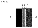
- FIG. 3 is used to describe the structural materials used when the anode for alkaline water electrolysis according to the present invention is used in an alkaline water electrolytic cell.
- numeral 5 represents the anode
- 6 represents a diaphragm (electrolysis diaphragm)
- 7 represents the cathode
- Numeral 8 represents an anode chamber
- 9 represents a cathode chamber.
- the cathode 7 it is necessary to select a substrate material that can withstand alkaline water electrolysis and a catalyst with a small cathode overpotential.
- materials that can be used as the cathode substrate include simple nickel, or a nickel substrate that has been coated with an active cathode.
- a nickel expanded mesh or a porous nickel expanded mesh can be used favorably as the cathode substrate.
- materials that can be used favorably as the electrode catalyst material for the cathode include the same electrode catalyst materials as those used in the electrode catalyst layer described above.
- asbestos, nonwoven fabrics, ion exchange membranes, porous polymer membranes, and composite membranes of an inorganic material and an organic polymer may be used.
- an ion-permeable membrane formed by disposing an organic fiber fabric in a mixture of a hydrophilic inorganic material such as a calcium phosphate compound or calcium fluoride and an organic binder material selected from among polysulfone, polypropylene and polyvinylidene fluoride may be used.
- an ion-permeable membrane containing a stretched organic fiber fabric in a film-forming mixture composed of a particulate inorganic hydrophilic material selected from among oxides and hydroxides of antimony and zirconium, and an organic binder selected from among fluorocarbon polymers, polysulfone, polypropylene, polyvinyl chloride and polyvinyl butyral may also be used.
- the electrolyte In the alkaline water electrolysis in the present invention, a solution obtained by adding a high-concentration alkaline water until a prescribed alkali concentration is achieved is used as the electrolyte.
- the electrolyte is preferably a caustic alkali such as caustic potash or caustic soda.
- the concentration of the electrolyte is preferably from 1.5 to 40% by mass. In terms of suppressing power consumption, a concentration of 15 to 40% by mass, which represents the region in which the electrical conductivity is large, is particularly preferred. However, if consideration is also given to the costs associated with the electrolysis, and the corrosiveness, viscosity and usability of the electrolyte, then a concentration of 20 to 30% by mass is even more desirable.
- a nickel mesh was etched for 3 minutes in boiling 20% hydrochloric acid, and was then baked at 500°C for 30 minutes to prepare a nickel electrode substrate.
- Ni nitrate and Co nitrate were dissolved in pure water in amounts that yielded 33.3 mol% of nickel and 66.7 mol% of cobalt, thus forming a coating solution. That coating solution was applied to the substrate in an amount that provided a metal amount of 1 g/m 2 per application.
- thermal decomposition was performed in an air circulating electric oven (350°C, 15 minutes). These steps were performed 4 times, thus producing an NiCo 2 O 4 catalyst layer containing an amount of metal of 4 g/m 2 .
- an iridium hexammine solution was applied in an amount sufficient to produce an amount of iridium oxide, calculated as the amount of iridium metal, of 1 g/m 2 .
- thermal decomposition was performed in an air circulating electric oven (350°C, 15 minutes), thus producing an electrode having an electrode catalyst layer composed of a stacked structure of an NiCo 2 O 4 catalyst layer and an IrO 2 catalyst layer.
- the overpotential of that electrode was measured in a 25 wt% solution of potassium hydroxide at 80°C, at current densities of 4 kA/m 2 and 6 kA/m 2 .
- Example 2 Using the iridium hexammine solution prepared in Example 1, iridium oxide was applied to the NiCo 2 O 4 catalyst layer formed in Example 1 in an amount sufficient to produce an amount of iridium oxide, calculated as the amount of iridium metal, of 1 g/m 2 . Subsequently, thermal decomposition was performed in an air circulating electric oven (450°C, 15 minutes), thus forming an electrode catalyst layer composed of a stacked structure of an NiCo 2 O 4 catalyst layer and an IrO 2 catalyst layer. The overpotential was measured using the same method as Example 1.
- Example 2 Using the iridium hexammine solution prepared in Example 1, iridium oxide was applied to the NiCo 2 O 4 catalyst layer formed in Example 1 in an amount sufficient to produce an amount of iridium oxide, calculated as the amount of iridium metal, of 1 g/m2. Subsequently, thermal decomposition was performed in an air circulating electric oven (550°C, 15 minutes), thus forming an electrode catalyst layer composed of a stacked structure of an NiCo 2 O 4 catalyst layer and an IrO 2 catalyst layer. The overpotential was measured using the same method as Example 1.
- Ni nitrate, Co nitrate and Ir nitrate were dissolved in pure water in amounts that yielded 31 mol% of nickel, 62 mol% of cobalt and 7 mol% of iridium, thus forming a coating solution, and this coating solution was applied to the substrate prepared in Example 1.
- thermal decomposition was performed in an air circulating electric oven (350°C, 15 minutes) thus forming a mixed catalyst layer in which the IrO 2 catalyst was highly dispersed within the NiCo 2 O 4 catalyst layer.
- These steps formed a catalyst layer containing 1 g/m 2 of nickel and cobalt and 0.25 g/m 2 of iridium, and by performing these steps 4 times, an electrode was produced.
- the overpotential was measured using the same method as Example 1.
- Example 4 With the exception of performing the thermal decomposition coating in an air circulating electric oven (450°C, 15 minutes), a mixed catalyst layer in which the IrO 2 catalyst was highly dispersed within the NiCo 2 O 4 catalyst layer was formed under the same conditions as Example 4. The overpotential was measured using the same method as Example 1.
- Ni nitrate, Co nitrate and La nitrate were dissolved in pure water in amounts that yielded 10 mol% of nickel, 40 mol% of cobalt and 50 mol% of lanthanum, thus preparing a coating solution.
- This coating solution was applied to the substrate prepared in Example 1, and thermal decomposition was then performed in an air circulating electric oven (350°C, 15 minutes), thus forming a first catalyst layer 2 composed of LaNi 0.2 Co 0.8 O 3 .
- iridium oxide was applied to the first catalyst layer 2 in an amount sufficient to produce an amount of iridium oxide, calculated as the amount of iridium metal, of 1 g/m 2 .
- Ni nitrate, Co nitrate, La nitrate and Ir nitrate were dissolved in pure water in amounts that yielded 9 mol% of nickel, 36 mol% of cobalt, 44 mol% of lanthanum and 11 mol% of iridium, thus preparing a coating solution.
- This coating solution was applied to the substrate prepared in Example 1, and thermal decomposition was then performed in an air circulating electric oven (350°C, 15 minutes). By performing these steps 4 times, a mixed catalyst layer containing a mixture of LaNi 0.2 Co 0.8 O 3 and iridium oxide was formed.
- the amounts of the catalyst components within the catalyst layer were 4 g/m 2 for nickel, cobalt and lanthanum, and 1 g/m 2 for iridium.
- the overpotential of this electrode was measured using the same method as Example 1.
- Ni nitrate, Co nitrate and Ru nitrate were dissolved in pure water in amounts that yielded 29 mol% of nickel, 58 mol% of cobalt and 13 mol% of ruthenium, thus forming a coating solution.
- This coating solution was applied to the substrate prepared in Example 1.
- thermal decomposition was performed in an air circulating electric oven (350°C, 15 minutes). These steps were performed 4 times, thus obtaining a mixed catalyst layer in which the RuO 2 catalyst was highly dispersed within the NiCo 2 O 4 catalyst layer.
- the amounts of the catalyst components within the catalyst layer, calculated as the amounts of the component metals, were 4 g/m 2 for nickel and cobalt, and 1 g/m 2 for ruthenium.
- the overpotential of the electrode was measured using the same method as Example 1.
- Ni nitrate, Co nitrate and Ru nitrate were dissolved in pure water in amounts that yielded 29 mol% of nickel, 58 mol% of cobalt and 13 mol% of ruthenium, thus forming a coating solution.
- This coating solution was applied to the substrate prepared in Example 1.
- thermal decomposition was performed in an air circulating electric oven (450°C, 15 minutes). These steps were performed 4 times, thus obtaining a mixed catalyst layer in which the RuO 2 catalyst was highly dispersed within the NiCo 2 O 4 catalyst layer.
- the amounts of the catalyst components within the catalyst layer, calculated as the amounts of the component metals, were 4 g/m 2 for nickel and cobalt, and 1 g/m 2 for ruthenium.
- the overpotential of the electrode was measured using the same method as Example 1.
- a nickel mesh was etched for 3 minutes in boiling 20% hydrochloric acid, and was then baked at 500°C for 30 minutes to prepare a nickel electrode.
- the overpotential of that electrode was measured in a 25 wt% solution of potassium hydroxide at 80°C, at current densities of 4 kA/m 2 and 6 kA/m 2 .
- Ni nitrate and Co nitrate were dissolved in pure water in amounts that yielded 33.3 mol% of nickel and 66.7 mol% of cobalt, thus forming a coating solution. That coating solution was applied to the substrate produced in Comparative Example 1 in an amount that provided a metal amount of 1 g/m 2 per application, and thermal decomposition was then performed in an air circulating electric oven (350°C, 15 minutes). These steps were performed 4 times, thus producing an electrode containing an amount of metal of 4 g/m 2 . The overpotential of that electrode was measured in a 25 wt% solution of potassium hydroxide at 80°C, at current densities of 4 kA/m 2 and 6 kA/m 2 .
- An electrode was produced using the same method as Comparative Example 2.
- the firing temperature was set to 450°C.
- the overpotential of the electrode was measured in a 25 wt% solution of potassium hydroxide at 80°C, at current densities of 4 kA/m 2 and 6 kA/m 2 .
- An electrode was produced using the same method as Comparative Example 2.
- the firing temperature was set to 550°C.
- the overpotential of the electrode was measured in a 25 wt% solution of potassium hydroxide at 80°C, at current densities of 4 kA/m 2 and 6 kA/m 2 .
- Ni nitrate, Co nitrate and La nitrate were dissolved in pure water in amounts that yielded 10 mol% of nickel, 40 mol% of cobalt and 50 mol% of lanthanum, thus preparing a coating solution.
- This coating solution was applied to the substrate prepared in Comparative Example 1, and thermal decomposition was then performed in an air circulating electric oven (350°C, 15 minutes), thus forming a catalyst layer.
- the overpotential was measured using the same method as Comparative Example 1.
- the oxygen overpotential was extremely high, with values of 320 mV at 4 kA/m 2 and 340 mV at 6 kA/m 2 .
- the overpotential was from 276 to 325 mV at 4 kA/m 2 and from 284 to 332 mV at 6 kA/m 2 .
- the overpotential was high, with values of 287 mV at 4 kA/m 2 and 297 mV at 6 kA/m 2 .
- IrO 2 on NiCo 2 O 4 means the IrO 2 catalyst layer was stacked on the surface of the NiCo 2 O 4 .
- IrO 2 in NiCo 2 O 4 means a mixed layer in which the IrO 2 had been mixed within the NiCo 2 O 4 .
- Electrodes were prepared in the same manner as Example 1, with the amount of Ir varied from 0 g/m 2 to 1.8 g/m 2 .
- the oxygen overpotential was measured using the same method as Example 1.
Landscapes
- Chemical & Material Sciences (AREA)
- Engineering & Computer Science (AREA)
- Materials Engineering (AREA)
- Organic Chemistry (AREA)
- Chemical Kinetics & Catalysis (AREA)
- Electrochemistry (AREA)
- Metallurgy (AREA)
- Inorganic Chemistry (AREA)
- Electrodes For Compound Or Non-Metal Manufacture (AREA)
- Electrolytic Production Of Non-Metals, Compounds, Apparatuses Therefor (AREA)
Abstract
Description
- The present invention relates to an anode used in alkaline water electrolysis, and relates particularly to an anode for alkaline water electrolysis that requires a low cell voltage and a method for producing the anode.
- Hydrogen is a secondary energy source that is suitable for storage and transport, and has little environmental impact. As a result, hydrogen energy systems that use hydrogen as an energy carrier are attracting much interest. Currently, hydrogen is mainly produced by steam reforming of fossil fuels or the like. From the viewpoints of problems such as global warming and fossil fuel depletion, the importance of alkaline water electrolysis which uses renewable energy such as solar cells, wind power or hydroelectric power as a power source continues to increase.
- Water electrolysis can be broadly classified into two types. One type is alkaline water electrolysis, which uses a high-concentration alkaline aqueous solution as the electrolyte. The other type is solid polymer water electrolysis, which uses a diamond electrode and uses a solid polymer electrolyte (SPE) as the electrolyte. When large-scale hydrogen production is performed by water electrolysis, it is considered that alkaline water electrolysis using an inexpensive material such as an iron-based metal of nickel or the like is more suitable than solid polymer water electrolysis using a diamond electrode.
- The electrode reactions at the two electrodes are as follows.
- Anode reaction:
2OH- → H2O + 1/2O2 + 2e- (1)
- Cathode reaction:
2H2O + 2e- → H2 + 2OH- (2)
- High-concentration alkaline aqueous solutions increase in conductivity as the temperature increases, but the corrosiveness also increases. Accordingly, the upper limit for the operating temperature is suppressed to about 80 to 90°C. The development of electrolyzer structural materials and various piping materials that are capable of withstanding higher temperatures and high-concentration alkaline aqueous solutions, and the development of low-resistance diaphragms and electrodes having increased surface area and provided with a catalyst have enabled electrolysis performance to be improved to about 1.7 to 1.9 V at a current density of 0.3 to 0.4 Acm-2 (efficiency: 78 to 87%).
- The anode for alkaline water electrolysis typically uses a nickel-based material that is stable in the high-concentration alkaline aqueous solution, and it has been reported that a Ni-based electrode has a lifespan of several decades or longer in alkaline water electrolysis that uses a stable power source (Non-Patent
Documents 1 and 2). However, Ni electrodes have a high overpotential, and suffer from poor productivity. - Conventionally, porous nickel or Ni or an alloy thereof has been used as the substrate of the anode for oxygen generation used in alkaline water electrolysis (Patent Document 1).
- Further, the following types of metals or metal oxides have conventionally been used as the electrode catalyst layer of the anode for oxygen generation used in alkaline water electrolysis.
- (1) Raney nickel (Patent Document 1)
- (2) Platinum-group metals (
Patent Documents 2 to 4)
Patent Document 2 discloses an anode that uses nickel and rhodium. Patent Document 3 discloses an anode that uses nickel, cobalt or silver, together with ruthenium, rhodium or iridium. Patent Document 4 discloses an electrode that uses platinum. - (3) Platinum-group metal oxides such as ruthenium oxide and iridium oxide (Patent Document 5)
- (4) Alloys of a first metal composed of at least one metal selected from among iron, titanium, niobium, zirconium, tantalum, tin, molybdenum and bismuth, and a second metal composed of at least one metal selected from among nickel, cobalt, silver and platinum (Patent Document 6)
- (5) Alloy systems based on nickel such as Ni-Co and Ni-Fe, nickel having an expanded surface area, and spinel Co3O4 and NiCo2O4 as ceramic materials (
Patent Documents 7 and 8) - (6) Conductive oxides such as perovskite LaCoO3 and La0.6St0.4CoO3 (Patent Document 9)
-
- Patent Document 1:
JP 55-011132 A - Patent Document 2:
JP 57-052432 B - Patent Document 3:
JP 61-010557 B - Patent Document 4:
JP 2009-242922 A - Patent Document 5:
JP 57-198289 A - Patent Document 6:
JP 57-200581 A - Patent Document 7:
JP 01-028837 B - Patent Document 8:
JP 61-250189 A - Patent Document 9:
JP 2009-179871 A -
- Non-Patent Document 1: P.W.T. Lu, S. Srinivasan, J. Electrochem. Soc., 125, 1416 (1978)
- Non-Patent Document 2: C.T. Bowen, Int. J. Hydrogen Energy, 9, 59 (1984)
- However, conventional electrodes used in alkaline water electrolysis all exhibit a high overpotential, and suffer from low productivity. Further reductions in the overpotential are required for practical applications.
- Objects of the present invention are to provide an anode for alkaline water electrolysis that has a low cell voltage while retaining good corrosion resistance, and to provide a method for producing such an anode.
- One aspect in the present invention is an anode for alkaline water electrolysis containing a conductive substrate having at least a surface composed of nickel or a nickel-based alloy, and an electrode catalyst layer formed on the surface of the conductive substrate, wherein a catalyst component that constitutes the electrode catalyst layer contains a first catalyst component having either a nickel-cobalt spinel oxide represented by a structural formula NiCo2O4, or a lanthanide-nickel-cobalt perovskite oxide represented by a structural formula XNiaCo1-aO3 (wherein X represents at least one metal selected from among the lanthanides including lanthanum, cerium and praseodymium, and 0<a<1), and a second catalyst component having at least one of iridium oxide and ruthenium oxide.
- In this first aspect, the structural formula of the lanthanide-nickel-cobalt perovskite oxide is preferably XNi0.2Co0.8O3.
- In the first aspect, it is preferable that the lanthanide is lanthanum, and the lanthanide-nickel-cobalt perovskite oxide is a lanthanum-nickel-cobalt perovskite oxide.
- In the first aspect, the electrode catalyst layer is preferably formed using a mixture of the first catalyst component and the second catalyst component.
- In the first aspect, the electrode catalyst layer is preferably composed of an electrode catalyst layer with a stacked structure in which a first catalyst layer formed from the first catalyst component and a second catalyst layer formed from the second catalyst component are stacked.
- In the first aspect, it is preferable that the first catalyst layer is formed on the surface of the conductive substrate, and the second catalyst layer is formed on the surface of the first catalyst layer.
- In the first aspect, the amount of the second catalyst component, calculated as an amount of the component metal, is preferably at least 0.2 g/m2.
- A second aspect in the present invention is a method for producing an anode for alkaline water electrolysis that includes a step of applying, to a surface of a conductive substrate having at least the surface composed of nickel or a nickel-based alloy, a first solution which is either a solution obtained by mixing nickel ions and cobalt ions so that the molar ratio between the amounts of the respective metals is 1:2, or a solution obtained by mixing metal ions of at least one metal selected from among the lanthanides including lanthanum, cerium and praseodymium, together with nickel ions and cobalt ions so that the molar ratio between the amounts of the respective metals is 1:a:1-a (0<a<1), and a second solution containing at least one of iridium ions and ruthenium ions, and a step of subjecting the conductive substrate to a heat treatment at a temperature from 350°C to 550°C in an oxygen-containing atmosphere, thereby forming an electrode catalyst layer composed of a first catalyst component having either a nickel-cobalt spinel oxide represented by a structural formula NiCo2O4, or a lanthanide-nickel-cobalt perovskite oxide represented by a structural formula XNiaCo1 aO3 (wherein X represents at least one metal selected from among the lanthanides including lanthanum, cerium and praseodymium, and 0<a<1), and a second catalyst component having at least one of iridium oxide and ruthenium oxide.
- In the second aspect, it is preferable that a mixture of the first solution and the second solution is applied to the surface of the conductive substrate having at least the surface composed of nickel or a nickel-based alloy, and the conductive substrate is then subjected to the heat treatment to form an electrode catalyst layer in which the first catalyst component and the second catalyst component are mixed.
- In the second aspect, it is preferable that the first solution and the second solution are applied separately to the surface of the conductive substrate having at least the surface composed of nickel or a nickel-based alloy, and that the conductive substrate is subjected to a heat treatment after application of each solution, thereby forming an electrode catalyst layer with a stacked structure in which the first catalyst component and the second catalyst component are stacked.
- In the second aspect, the heat treatment is preferably performed at a temperature from 350°C to 400°C in an oxygen-containing atmosphere.
- In the second aspect, the amount of the second catalyst component, calculated as an amount of the component metal, is preferably at least 0.2 g/m2.
- In the second aspect, the lanthanide perovskite oxide is preferably a lanthanum-nickel-cobalt perovskite oxide.
- In the second aspect, the structural formula of the lanthanide-nickel-cobalt perovskite oxide is preferably XNi0.2Co0.8O3.
- In the second aspect, the lanthanide is preferably lanthanum.
- In the second aspect, the metal ions of at least one metal selected from among the lanthanides including lanthanum, cerium and praseodymium are preferably lanthanum ions.
- In the second aspect, the second solution is preferably an acidic solution.
- In the second aspect, the second solution is preferably an alkaline solution.
- The anode for alkaline water electrolysis according to the present invention contains a conductive substrate having at least a surface composed of nickel or a nickel-based alloy, and an electrode catalyst layer formed on the surface of the conductive substrate, and by forming the catalyst component that constitutes the electrode catalyst layer from a first catalyst component having a nickel-cobalt spinel oxide or a lanthanide-nickel-cobalt perovskite oxide, and a second catalyst component having at least one of iridium oxide and ruthenium oxide, an overpotential that is as much as 60 mV lower than conventional nickel electrodes can be achieved.
- In the anode for alkaline water electrolysis according to the present invention, by also ensuring that the second catalyst component having at least one of iridium oxide and ruthenium oxide is included in an amount, calculated in terms of the amount of metal, that is at least 0.2 g/m2, an even lower overpotential can be achieved.
- Moreover, by subjecting the anode for alkaline water electrolysis according to the present invention to a heat treatment (thermal decomposition) in an oxygen-containing atmosphere at a temperature from 350°C to 550°C, and preferably from 350°C to 400°C, thermal decomposition of the first catalyst component and the second catalyst component is able to proceed satisfactorily, meaning the desired oxides can be obtained, and the coating strength onto the electrode substrate and the adhesive strength between the catalyst layers can be enhanced. As a result, separation of the catalyst component from the catalyst layer does not occur, the corrosion resistance improves, and a low overpotential can be achieved.
- It is thought that the reason these improvements are obtained for the anode for alkaline water electrolysis is that by selecting appropriate catalyst components and an appropriate heat treatment temperature, at least one of iridium oxide and ruthenium oxide is highly dispersed in either the nickel-cobalt spinel oxide or the lanthanide-nickel-cobalt perovskite oxide, thus enabling a reduction in the over potential.
-
-
FIG. 1a is a cross-sectional view illustrating one embodiment of the anode for alkaline water electrolysis according to the present invention. -
FIG. 1b is a cross-sectional view illustrating another embodiment of the anode for alkaline water electrolysis according to the present invention. -
FIG. 2 is a graph illustrating the relationship between the proportion of the second catalyst component used in the anode for alkaline water electrolysis of the present invention and the oxygen overpotential. -
FIG. 3 is a schematic view of an electrolytic cell that uses the anode for alkaline water electrolysis according to the present invention. - The anode for alkaline water electrolysis according to the present invention and the method for producing the anode are described below with reference to the drawings.
-
FIG. 1a is a cross-sectional view illustrating one embodiment of the anode for alkaline water electrolysis according to the present invention. The anode for alkaline water electrolysis has a stacked structure containing aconductive substrate 1 having at least the surface composed of nickel or a nickel-based alloy, afirst catalyst layer 2 formed from a first catalyst component on the surface of theconductive substrate 1, and a second catalyst layer 3 formed from a second catalyst component. -
FIG. 1b is a cross-sectional view illustrating another embodiment of the anode for alkaline water electrolysis according to the present invention. This anode for alkaline water electrolysis contains theconductive substrate 1 having at least the surface composed of nickel or a nickel-based alloy, and a mixed catalyst layer 4 containing a mixture of a first catalyst component and a second catalyst component formed on the surface of theconductive substrate 1. - First are descriptions of the conductive substrate of the anode for alkaline water electrolysis that constitutes the present invention, and the electrode catalyst layer (the catalyst layer) formed on the surface of the conductive substrate.
- For reasons of conductivity and chemical stability, the
conductive substrate 1 uses stainless steel, nickel, a nickel-based alloy, iron, or a Ni-plated iron material. At least the surface of theconductive substrate 1 is formed from nickel or a nickel-based alloy. The thickness of theconductive substrate 1 is preferably from 0.05 to 5 mm. - The
conductive substrate 1 preferably has a shape with openings for removing the generated oxygen bubbles. Accordingly, a nickel expanded mesh or a porous nickel expanded mesh or the like can be used favorably as theconductive substrate 1. The porosity of theconductive substrate 1 is preferably from 10 to 95%. - In order to enhance the adhesion to the catalyst layer, the surface of the
conductive substrate 1 is preferably subjected to a surface roughening treatment such as a blast treatment in which a powder is blasted onto the surface, an etching treatment that uses an acid that can dissolve the substrate, or a plasma spraying treatment. Moreover, in order to remove contaminant particles of metals or organic matter from the substrate surface, a chemical etching treatment is preferably performed. The amount of the conductive substrate consumed by the chemical etching treatment is preferably about 30 to 400 g/m2. - Moreover, when forming the catalyst layer on the surface of the
conductive substrate 1, a coating solution composed of an acid solution or an alkali solution is applied to the surface of theconductive substrate 1. In order to protect theconductive substrate 1 formed from nickel or a nickel-based alloy, the substrate is preferably fired in advance in the open atmosphere at a temperature of 450°C to 550°C for a period of 5 to 20 minutes to form a Ni oxide layer on the substrate surface. - In terms of durability, the catalyst of the anode for alkaline water electrolysis may be composed solely of nickel or a nickel-based alloy. However, a catalyst composed solely of nickel or a nickel-based alloy has a high overpotential. Accordingly, in the present invention, a specific electrode catalyst layer is formed on the surface of the
conductive substrate 1 which has at least the surface composed of nickel or a nickel-based alloy. The catalyst component that constitutes the electrode catalyst layer is composed of a first catalyst component having a nickel-cobalt spinel oxide or a lanthanide-nickel-cobalt perovskite oxide, and a second catalyst component having at least one of iridium oxide and ruthenium oxide. - The structural formula of the nickel-cobalt spinel oxide used in the present invention is represented by NiCo2O4.
- The structural formula of the lanthanide-nickel-cobalt perovskite oxide used in the present invention is a perovskite oxide represented by the general formula XYO3 in which the X component is at least one metal selected from among the lanthanides including lanthanum, cerium and praseodymium, and the Y component is composed of nickel and cobalt. In other words, the perovskite oxide is represented by the structural formula XNiaCo1-aO3 (wherein X represents at least one metal selected from among the lanthanides including lanthanum, cerium and praseodymium, and 0<a<1).
- The lanthanide is preferably lanthanum. The structural formula of such compounds is represented by LaNiaCo1-aO3, and the use of LaNi0.2Co0.8O3 is preferable.
- The perovskite oxides disclosed in
Patent Document 9 include lanthanum-strontium-cobalt perovskites, lanthanum-strontium-iron perovskites, and the like, and are limited to perovskites that use cobalt or iron as the Y component, with no disclosure nor mention made of the type of perovskites used in the present invention that use nickel as one of the Y components. - The overpotential was unable to be reduced adequately using an electrode catalyst layer for the anode for alkaline water electrolysis composed solely of the first catalyst component having a nickel-cobalt spinel oxide or a lanthanide-nickel-cobalt perovskite oxide. Consequently, an electrode catalyst layer containing a highly dispersed second catalyst component having at least one of iridium oxide and ruthenium oxide together with the first catalyst component is used.
- The electrode catalyst layer of the anode for alkaline water electrolysis illustrated in
FIG. 1a has a stacked structure of the firstelectrode catalyst layer 2 formed from the first catalyst and the second electrode catalyst layer 3 formed from the second catalyst component. In FIG. la, each of these layers may be formed from a single layer, but a firstelectrode catalyst layer 2 composed of a plurality of layers may be formed, and a second electrode catalyst layer 3 composed of a plurality of layers may also be formed. - Further, as illustrated in
FIG. 1b , the mixed catalyst layer 4 for an anode for alkaline water electrolysis, prepared as a mixed layer by mixing the first catalyst component and the second catalyst component, may also be used as the electrode catalyst layer. - The steps for producing the anode for alkaline water electrolysis illustrated in
FIG. 1a are described below. - As illustrated in FIG. la, the second electrode catalyst layer having the second catalyst component composed of at least one of iridium oxide and ruthenium oxide is formed on the surface of the first
electrode catalyst layer 2 composed of the first catalyst component having a nickel-cobalt spinel oxide or a lanthanide-nickel-cobalt perovskite oxide. In those cases where pluralities of the firstelectrode catalyst layer 2 and the second electrode catalyst layer 3 are to be formed, a stacked structure is formed by sequentially stacking an additional firstelectrode catalyst layer 2 and second electrode catalyst layer 3 on top of the second electrode catalyst layer 3. - In order to form this type of stacked structure of the
first catalyst layer 2 and the second catalyst layer 3, first, a solution (first solution) obtained either by mixing nickel ions and cobalt ions so that the molar ratio between the amounts of the respective metals is 1:2, or by mixing metal ions of at least one metal selected from among the lanthanides including lanthanum, cerium and praseodymium, together with nickel ions and cobalt ions, so that the molar ratio between the amounts of the respective metals is 1:a:1-a (0<a<1), is applied to the surface of theconductive substrate 1 having at least the surface composed of nickel or a nickel-based alloy. Subsequently, theconductive substrate 1 is subjected to a heat treatment at a temperature from 350°C to 550°C in an oxygen-containing atmosphere, thereby forming thefirst catalyst layer 2 composed of the first catalyst component having either a nickel-cobalt spinel oxide represented by the structural formula NiCo2O4, or a lanthanide-nickel-cobalt perovskite oxide represented by the structural formula XNiaCo1-aO3 (wherein X represents at least one metal selected from among the lanthanides including lanthanum, cerium and praseodymium, and 0<a<1). - When forming the
first catalyst layer 2 composed of the first catalyst component, the metal ions of at least one metal selected from among the lanthanides including lanthanum, cerium and praseodymium, and the nickel ions and cobalt ions may each be used in the form of the respective nitrate salt. - Subsequently, a solution (second solution) containing at least one of iridium ions and ruthenium ions is applied to the surface of the
first catalyst layer 2. Theconductive substrate 1 is then subjected to a heat treatment at a temperature from 350°C to 550°C in an oxygen-containing atmosphere, thereby forming the second catalyst layer 3 composed of the second catalyst component. - In this manner, the
first catalyst layer 2 and the second catalyst layer 3 are formed as a stacked structure. Thefirst catalyst layer 2 and the second catalyst layer 3 may be stacked in any order. In those cases where an electrode catalyst layer with a stacked structure having two or more stacked layers is formed, the second catalyst component in the second catalyst layer 3 migrates into thefirst catalyst layer 2. In other words, the first catalyst component and the second catalyst component are mixed, at least at the interface between thefirst catalyst layer 2 and the second catalyst layer 3. - In those cases where the
first catalyst layer 2 and the second catalyst layer 3 are formed as a stacked structure, if a nitrate salt solution is used as the solution containing at least one of iridium ions and ruthenium ions, then there is a possibility that the nitrate ions may corrode and cause detachment of the nickel-cobalt spinel oxide or the lanthanide-nickel-cobalt perovskite oxide. Accordingly, an alkaline solution is preferably used as the solution containing at least one of iridium ions and ruthenium ions. - The steps for producing the anode for alkaline water electrolysis illustrated in
FIG. 1b are described below. - In this case, rather than forming the electrode catalyst layer as a stacked structure, the second solution is added to and mixed with the first solution to prepare a mixed solution. This mixed solution is then applied to the surface of the
conductive substrate 1 having at least the surface composed of nickel or a nickel-based alloy. Subsequently, heating is performed at a temperature of 350 to 550°C, thereby forming the mixed catalyst layer 4 containing a mixture of the first catalyst component and the second catalyst component. - In those cases where the mixed catalyst layer 4 containing a mixture of the first catalyst component and the second catalyst component is formed in this manner, a nitrate solution may be used as the solution containing at least one of iridium ions and ruthenium ions.
- The heat treatment must be performed at a temperature from 350°C to 550°C. If the treatment temperature is 350°C or lower, then the thermal decomposition of the first catalyst component and the second catalyst component is insufficient, the coating strength onto the electrode substrate and the adhesive strength between the catalyst layers are inadequate, and the catalyst components tend to separate from the catalyst layer. On the other hand, if the temperature is 550°C or higher, then oxidation of the first catalyst component and the second catalyst component tends to proceed, and the overpotential increases. Oxidation of the first catalyst component and the second catalyst component tends to start when the temperature is 400°C or higher. Consequently, the temperature of the heat treatment is preferably from 350°C to 400°C.
- The time of the heat treatment is preferably from 5 to 60 minutes, and more preferably from 5 to 20 minutes. If the time of the heat treatment is 5 minutes or less, then the catalyst production is insufficient, the coating strength onto the electrode substrate and the adhesive strength between the catalyst layers are inadequate, and the catalyst components tend to separate from the catalyst layer. On the other hand, if the time is 60 minutes or longer, then oxidation of the catalyst components tends to proceed, and the overpotential increases. Oxidation of the catalyst components tends to start when the treatment time is 20 minutes or longer. Consequently, the time of the heat treatment is more preferably from 5 to 20 minutes.
- The amount of iridium oxide or ruthenium oxide, calculated as an amount of the component metal, is preferably at least 0.2 g/m2. In order to maintain a low overpotential, an amount of iridium metal or ruthenium metal of at least 0.2 g/m2 is required. If this amount is less than 0.2 g/m2, the overpotential increases.
-
FIG. 2 illustrates the relationship between the proportion of iridium oxide (IrO2) used in an anode for alkaline water electrolysis having the structure illustrated inFIG. 1a and the oxygen overpotential. The anode for alkaline water electrolysis has a structure in which thefirst catalyst layer 2 composed of the nickel-cobalt spinel oxide (NiCo2O4) as the first catalyst component is formed on the surface of theconductive substrate 1 formed from a nickel alloy, and the second catalyst layer 3 composed of iridium oxide (IrO2) as the second catalyst component is formed on the surface of thefirst catalyst layer 2. Using this anode for alkaline water electrolysis, the overpotential was measured in a 25 wt% solution of potassium hydroxide at 80°C and a current density of 4 kA/m2. - Based on
FIG. 2 , it is evident that by ensuring that the amount of iridium oxide of the second catalyst component, calculated as the amount of iridium metal, is at least 0.2 g/m2, the oxygen overpotential can be kept low. - Further, similar results were obtained when ruthenium oxide was either used alone or mixed with iridium oxide as the second catalyst component.
- In the method for forming the catalyst layer according to the present invention, coating film formation methods such as the CVD and PVD methods described below can also be used as alternative methods to the above heat treatment method.
- (1) CVD method: a gas containing a metal is decomposed using a plasma to generate metal atoms, and a coating film is formed on a substrate held at a high temperature (of about 800°C).
- (2) PVD methods: these include sputtering methods and ion plating methods.
- A sputtering method is a method in which ions of argon or the like are collided onto a solid metal to eject metal atoms as particles. Because the sputtered particles are substantially electrically neutral, the energy of the particles that form the coating film is low.
- An ion plating method is a method in which an electron flow is generated, the resulting heat is used to evaporate a solid metal to obtain metal atoms, and at the same time, most of the atoms are ionized, with the ions forming the coating film.
- Ion plating methods are classified as arc ion plating, hollow cathode and electron gun depending on the method used for generating the electron current.
- The arc ion plating method is a method in which a target is subjected to vacuum discharge between a cathode and an anode, thereby evaporating and ionizing material from the surface of the target. The ionization rate of the metal vapor is a high value of at least 80%, enabling a film having excellent density and adhesion to be formed at high speed. In the hollow cathode method, the ionization rate is moderate. In the electron gun method, the ionization rate is low.
- Next,
FIG. 3 is used to describe the structural materials used when the anode for alkaline water electrolysis according to the present invention is used in an alkaline water electrolytic cell. - In
FIG. 3 ,numeral 5 represents the anode, 6 represents a diaphragm (electrolysis diaphragm), and 7 represents the cathode.Numeral 8 represents an anode chamber, and 9 represents a cathode chamber. - For the
cathode 7, it is necessary to select a substrate material that can withstand alkaline water electrolysis and a catalyst with a small cathode overpotential. Examples of materials that can be used as the cathode substrate include simple nickel, or a nickel substrate that has been coated with an active cathode. In a similar manner to theanode 5, a nickel expanded mesh or a porous nickel expanded mesh can be used favorably as the cathode substrate. Examples of materials that can be used favorably as the electrode catalyst material for the cathode include the same electrode catalyst materials as those used in the electrode catalyst layer described above. - For the
diaphragm 6, asbestos, nonwoven fabrics, ion exchange membranes, porous polymer membranes, and composite membranes of an inorganic material and an organic polymer may be used. For example, an ion-permeable membrane formed by disposing an organic fiber fabric in a mixture of a hydrophilic inorganic material such as a calcium phosphate compound or calcium fluoride and an organic binder material selected from among polysulfone, polypropylene and polyvinylidene fluoride may be used. Further, an ion-permeable membrane containing a stretched organic fiber fabric in a film-forming mixture composed of a particulate inorganic hydrophilic material selected from among oxides and hydroxides of antimony and zirconium, and an organic binder selected from among fluorocarbon polymers, polysulfone, polypropylene, polyvinyl chloride and polyvinyl butyral may also be used. - In the alkaline water electrolysis in the present invention, a solution obtained by adding a high-concentration alkaline water until a prescribed alkali concentration is achieved is used as the electrolyte. The electrolyte is preferably a caustic alkali such as caustic potash or caustic soda. The concentration of the electrolyte is preferably from 1.5 to 40% by mass. In terms of suppressing power consumption, a concentration of 15 to 40% by mass, which represents the region in which the electrical conductivity is large, is particularly preferred. However, if consideration is also given to the costs associated with the electrolysis, and the corrosiveness, viscosity and usability of the electrolyte, then a concentration of 20 to 30% by mass is even more desirable.
- Next is a description of examples of the present invention, but the present invention is not limited to these examples. The catalyst composition, the firing temperature, the result of measuring the overpotential and the catalyst metal component ratio for each of Examples 1 to 9 and Comparative Examples 1 to 5 are shown in Table 1.
- Example 1 illustrates an example in which NiCo2O4 was used as the first catalyst component, IrO2 was used as the second catalyst component, the firing temperature was set to 350°C, and the first catalyst component and the second catalyst component were formed in a stacked structure.
- Example 2 illustrates an example in which NiCo2O4 was used as the first catalyst component, IrO2 was used as the second catalyst component, the firing temperature was set to 450°C, and the first catalyst component and the second catalyst component were formed in a stacked structure.
- Example 3 illustrates an example in which NiCo2O4 was used as the first catalyst component, IrO2 was used as the second catalyst component, the firing temperature was set to 550°C, and the first catalyst component and the second catalyst component were formed in a stacked structure.
- Example 4 illustrates an example in which NiCo2O4 was used as the first catalyst component, IrO2 was used as the second catalyst component, the firing temperature was set to 350°C, and the first catalyst component and the second catalyst component were formed as a mixed layer.
- Example 5 illustrates an example in which NiCo2O4 was used as the first catalyst component, IrO2 was used as the second catalyst component, the firing temperature was set to 450°C, and the first catalyst component and the second catalyst component were formed as a mixed layer.
- Example 6 illustrates an example in which LaNi0.2Co0.8O3 was used as the first catalyst component, IrO2 was used as the second catalyst component, the firing temperature was set to 350°C, and the first catalyst component and the second catalyst component were formed in a stacked structure.
- Example 7 illustrates an example in which LaNi0.2Co0.8O3 was used as the first catalyst component, IrO2 was used as the second catalyst component, the firing temperature was set to 350°C, and the first catalyst component and the second catalyst component were formed as a mixed layer.
- Example 8 illustrates an example in which NiCo2O4 was used as the first catalyst component, RuO2 was used as the second catalyst component, the firing temperature was set to 350°C, and the first catalyst component and the second catalyst component were formed as a mixed layer.
- Example 9 illustrates an example in which NiCo2O4 was used as the first catalyst component, RuO2 was used as the second catalyst component, the firing temperature was set to 450°C, and the first catalyst component and the second catalyst component were formed as a mixed layer.
- A nickel mesh was etched for 3 minutes in boiling 20% hydrochloric acid, and was then baked at 500°C for 30 minutes to prepare a nickel electrode substrate. Next, Ni nitrate and Co nitrate were dissolved in pure water in amounts that yielded 33.3 mol% of nickel and 66.7 mol% of cobalt, thus forming a coating solution. That coating solution was applied to the substrate in an amount that provided a metal amount of 1 g/m2 per application. Subsequently, thermal decomposition was performed in an air circulating electric oven (350°C, 15 minutes). These steps were performed 4 times, thus producing an NiCo2O4 catalyst layer containing an amount of metal of 4 g/m2.
- Thereafter, an iridium hexammine solution was applied in an amount sufficient to produce an amount of iridium oxide, calculated as the amount of iridium metal, of 1 g/m2. Subsequently, thermal decomposition was performed in an air circulating electric oven (350°C, 15 minutes), thus producing an electrode having an electrode catalyst layer composed of a stacked structure of an NiCo2O4 catalyst layer and an IrO2 catalyst layer.
- The overpotential of that electrode was measured in a 25 wt% solution of potassium hydroxide at 80°C, at current densities of 4 kA/m2 and 6 kA/m2.
- Using the iridium hexammine solution prepared in Example 1, iridium oxide was applied to the NiCo2O4 catalyst layer formed in Example 1 in an amount sufficient to produce an amount of iridium oxide, calculated as the amount of iridium metal, of 1 g/m2. Subsequently, thermal decomposition was performed in an air circulating electric oven (450°C, 15 minutes), thus forming an electrode catalyst layer composed of a stacked structure of an NiCo2O4 catalyst layer and an IrO2 catalyst layer. The overpotential was measured using the same method as Example 1.
- Using the iridium hexammine solution prepared in Example 1, iridium oxide was applied to the NiCo2O4 catalyst layer formed in Example 1 in an amount sufficient to produce an amount of iridium oxide, calculated as the amount of iridium metal, of 1 g/m2. Subsequently, thermal decomposition was performed in an air circulating electric oven (550°C, 15 minutes), thus forming an electrode catalyst layer composed of a stacked structure of an NiCo2O4 catalyst layer and an IrO2 catalyst layer. The overpotential was measured using the same method as Example 1.
- Ni nitrate, Co nitrate and Ir nitrate were dissolved in pure water in amounts that yielded 31 mol% of nickel, 62 mol% of cobalt and 7 mol% of iridium, thus forming a coating solution, and this coating solution was applied to the substrate prepared in Example 1. Subsequently, thermal decomposition was performed in an air circulating electric oven (350°C, 15 minutes) thus forming a mixed catalyst layer in which the IrO2 catalyst was highly dispersed within the NiCo2O4 catalyst layer. These steps formed a catalyst layer containing 1 g/m2 of nickel and cobalt and 0.25 g/m2 of iridium, and by performing these steps 4 times, an electrode was produced. The overpotential was measured using the same method as Example 1.
- With the exception of performing the thermal decomposition coating in an air circulating electric oven (450°C, 15 minutes), a mixed catalyst layer in which the IrO2 catalyst was highly dispersed within the NiCo2O4 catalyst layer was formed under the same conditions as Example 4. The overpotential was measured using the same method as Example 1.
- Ni nitrate, Co nitrate and La nitrate were dissolved in pure water in amounts that yielded 10 mol% of nickel, 40 mol% of cobalt and 50 mol% of lanthanum, thus preparing a coating solution. This coating solution was applied to the substrate prepared in Example 1, and thermal decomposition was then performed in an air circulating electric oven (350°C, 15 minutes), thus forming a
first catalyst layer 2 composed of LaNi0.2Co0.8O3. Subsequently, using the iridium hexammine solution prepared in Example 1, iridium oxide was applied to thefirst catalyst layer 2 in an amount sufficient to produce an amount of iridium oxide, calculated as the amount of iridium metal, of 1 g/m2. Subsequently, thermal decomposition was performed in an air circulating electric oven (350°C, 15 minutes), thus forming a second catalyst layer 3 composed of iridium oxide. This completed production of an electrode having an electrode catalyst layer with a stacked structure. The overpotential of the electrode was measured using the same method as Example 1. - Ni nitrate, Co nitrate, La nitrate and Ir nitrate were dissolved in pure water in amounts that yielded 9 mol% of nickel, 36 mol% of cobalt, 44 mol% of lanthanum and 11 mol% of iridium, thus preparing a coating solution. This coating solution was applied to the substrate prepared in Example 1, and thermal decomposition was then performed in an air circulating electric oven (350°C, 15 minutes). By performing these steps 4 times, a mixed catalyst layer containing a mixture of LaNi0.2Co0.8O3 and iridium oxide was formed. The amounts of the catalyst components within the catalyst layer, calculated as the amounts of the component metals, were 4 g/m2 for nickel, cobalt and lanthanum, and 1 g/m2 for iridium. The overpotential of this electrode was measured using the same method as Example 1.
- Ni nitrate, Co nitrate and Ru nitrate were dissolved in pure water in amounts that yielded 29 mol% of nickel, 58 mol% of cobalt and 13 mol% of ruthenium, thus forming a coating solution. This coating solution was applied to the substrate prepared in Example 1. Subsequently, thermal decomposition was performed in an air circulating electric oven (350°C, 15 minutes). These steps were performed 4 times, thus obtaining a mixed catalyst layer in which the RuO2 catalyst was highly dispersed within the NiCo2O4 catalyst layer. The amounts of the catalyst components within the catalyst layer, calculated as the amounts of the component metals, were 4 g/m2 for nickel and cobalt, and 1 g/m2 for ruthenium. The overpotential of the electrode was measured using the same method as Example 1.
- Ni nitrate, Co nitrate and Ru nitrate were dissolved in pure water in amounts that yielded 29 mol% of nickel, 58 mol% of cobalt and 13 mol% of ruthenium, thus forming a coating solution. This coating solution was applied to the substrate prepared in Example 1. Subsequently, thermal decomposition was performed in an air circulating electric oven (450°C, 15 minutes). These steps were performed 4 times, thus obtaining a mixed catalyst layer in which the RuO2 catalyst was highly dispersed within the NiCo2O4 catalyst layer. The amounts of the catalyst components within the catalyst layer, calculated as the amounts of the component metals, were 4 g/m2 for nickel and cobalt, and 1 g/m2 for ruthenium. The overpotential of the electrode was measured using the same method as Example 1.
- A nickel mesh was etched for 3 minutes in boiling 20% hydrochloric acid, and was then baked at 500°C for 30 minutes to prepare a nickel electrode. The overpotential of that electrode was measured in a 25 wt% solution of potassium hydroxide at 80°C, at current densities of 4 kA/m2 and 6 kA/m2.
- Ni nitrate and Co nitrate were dissolved in pure water in amounts that yielded 33.3 mol% of nickel and 66.7 mol% of cobalt, thus forming a coating solution. That coating solution was applied to the substrate produced in Comparative Example 1 in an amount that provided a metal amount of 1 g/m2 per application, and thermal decomposition was then performed in an air circulating electric oven (350°C, 15 minutes). These steps were performed 4 times, thus producing an electrode containing an amount of metal of 4 g/m2. The overpotential of that electrode was measured in a 25 wt% solution of potassium hydroxide at 80°C, at current densities of 4 kA/m2 and 6 kA/m2.
- An electrode was produced using the same method as Comparative Example 2. The firing temperature was set to 450°C. The overpotential of the electrode was measured in a 25 wt% solution of potassium hydroxide at 80°C, at current densities of 4 kA/m2 and 6 kA/m2.
- An electrode was produced using the same method as Comparative Example 2. The firing temperature was set to 550°C. The overpotential of the electrode was measured in a 25 wt% solution of potassium hydroxide at 80°C, at current densities of 4 kA/m2 and 6 kA/m2.
- Ni nitrate, Co nitrate and La nitrate were dissolved in pure water in amounts that yielded 10 mol% of nickel, 40 mol% of cobalt and 50 mol% of lanthanum, thus preparing a coating solution. This coating solution was applied to the substrate prepared in Comparative Example 1, and thermal decomposition was then performed in an air circulating electric oven (350°C, 15 minutes), thus forming a catalyst layer. The overpotential was measured using the same method as Comparative Example 1.
- The results are shown in Table 1.
- In Examples 1, 4, 6, 7 and 8, the overpotential was lowest, with values of 218 to 224 mV at 4 kA/m2 and 230 to 234 mV at 6 kA/m2.
- In contrast, with the Ni electrode of Comparative Example 1, the oxygen overpotential was extremely high, with values of 320 mV at 4 kA/m2 and 340 mV at 6 kA/m2. Even with the NiCo2O4 of Comparative Examples 2 to 4, the overpotential was from 276 to 325 mV at 4 kA/m2 and from 284 to 332 mV at 6 kA/m2. Even with the LaNi0.2Co0.8O3 of Comparative Example 5, the overpotential was high, with values of 287 mV at 4 kA/m2 and 297 mV at 6 kA/m2.
[Table 1] Examples Composition Firing temperature (°C) Overpotential Catalyst metal component ratio 4kA/m2 (mV) 6kA/m2 (mV) Ni(mol %) Co(mol %) La(mol %) Ir(mol %) Ru(mol %) Example 1 IrO2 on NiCo2O4 350 222 234 31 62 - 7 - Example 2 IrO2 on NiCo2O4 450 239 246 31 62 - 7 - Example 3 IrO2 on NiCo2O4 550 259 271 31 62 - 7 - Example 4 IrO2 in NiCo2O4 350 218 230 31 62 - 7 - Example 5 IrO2 in NiCo2O4 450 258 263 31 62 - 7 - Example 6 IrO2 on LaNi0.2Co0.8O3 350 224 230 9 36 44 11 - Example 7 IrO2 in LaNi0.2Co0.8O3 350 220 232 9 36 44 11 - Example 8 RuO2 in NiCo2O4 350 222 230 29 58 - - 13 Example 9 RuO2 in N iCo2O4 450 258 263 29 58 - - 13 Comparative Example 1 Ni - 320 340 100 - - - - Comparative Example 2 NiCo2O4 350 276 284 33.3 66.7 - - - Comparative Example 3 NiCo2O4 450 300 308 33.3 66.7 - - - Comparative Example 4 NiCo2O4 550 325 332 33.3 66.7 - - - Comparative Example 5 LaNi0.2Co0.8O3 350 287 297 10 40 50 - - - In Table 1, "IrO2 on NiCo2O4" means the IrO2 catalyst layer was stacked on the surface of the NiCo2O4. "IrO2 in NiCo2O4" means a mixed layer in which the IrO2 had been mixed within the NiCo2O4. These meanings of "on" and "in" have the same meanings for other components.
- Electrodes were prepared in the same manner as Example 1, with the amount of Ir varied from 0 g/m2 to 1.8 g/m2. The oxygen overpotential was measured using the same method as Example 1.
- Based on the results (
FIG. 2 ), it was evident that an overpotential of 220 mV could be achieved for amounts of iridium of at least 0.2 g/m2. - Using each of the above anodes from Comparative Example 1, Example 1 and Example 4, and using a Ru-based cathode for the cathode and a polyethersulfone-based membrane for the diaphragm, continuous electrolysis tests were conducted. The cell illustrated in
FIG. 3 was used, and the voltage was measured under conditions including 25% KOH, 80°C and 40 A/dm2. - The results revealed a cell voltage of 1.72 V for Comparative Example 1. In contrast, the cell voltage was 1.64 V for Example 1 and 1.69 V for Example 4, and the voltages were stable.
-
- 1:
- Nickel substrate
- 2:
- First catalyst layer
- 3:
- Second catalyst layer
- 4:
- Mixed catalyst layer
- 5:
- Anode
- 6:
- Diaphragm
- 7:
- Cathode
- 8:
- Anode chamber
- 9:
- Cathode chamber
Claims (18)
- An anode for alkaline water electrolysis comprising a conductive substrate having at least a surface composed of nickel or a nickel-based alloy, and an electrode catalyst layer formed on the surface of the conductive substrate, wherein
a catalyst component that constitutes the electrode catalyst layer comprises:a first catalyst component having a nickel-cobalt spinel oxide represented by a structural formula NiCo2O4, or a lanthanide-nickel-cobalt perovskite oxide represented by a structural formula XNiaCo1-aO3 (wherein X represents at least one metal selected from among lanthanides including lanthanum, cerium and praseodymium, and 0<a<1), anda second catalyst component having at least one of iridium oxide and ruthenium oxide. - The anode for alkaline water electrolysis according to Claim 1, wherein a structural formula of the lanthanide-nickel-cobalt perovskite oxide is XNi0.2Co0.8O3.
- The anode for alkaline water electrolysis according to Claim 1, wherein the lanthanide is lanthanum, and the lanthanide-nickel-cobalt perovskite oxide is a lanthanum-nickel-cobalt perovskite oxide.
- The anode for alkaline water electrolysis according to Claim 1, wherein the electrode catalyst layer is formed from a mixture of the first catalyst component and the second catalyst component.
- The anode for alkaline water electrolysis according to Claim 1, wherein the electrode catalyst layer is composed of an electrode catalyst layer with a stacked structure in which a first catalyst layer formed from the first catalyst component and a second catalyst layer formed from the second catalyst component are stacked.
- The anode for alkaline water electrolysis according to Claim 5, wherein the first catalyst layer is formed on the surface of the conductive substrate, and the second catalyst layer is formed on a surface of the first catalyst layer.
- The anode for alkaline water electrolysis according to any one of Claims 1, 4, 5 and 6, wherein an amount of the second catalyst component, calculated as an amount of a component metal, is at least 0.2 g/m2.
- A method for producing an anode for alkaline water electrolysis comprising:a step of applying, to a surface of a conductive substrate having at least the surface composed of nickel or a nickel-based alloy, a first solution which is either a solution obtained by mixing nickel ions and cobalt ions so that a molar ratio between amounts of the respective metals is 1:2, or a solution obtained by mixing metal ions of at least one metal selected from among lanthanides including lanthanum, cerium and praseodymium, together with nickel ions and cobalt ions, so that a molar ratio between amounts of the respective metals is 1:a:1-a (0<a<1), and a second solution containing at least one of iridium ions and ruthenium ions, anda step of subjecting the conductive substrate to a heat treatment at a temperature from 350°C to 550°C in an oxygen-containing atmosphere, thereby forming an electrode catalyst layer composed of a first catalyst component having either a nickel-cobalt spinel oxide represented by a structural formula NiCo2O4, or a lanthanide-nickel-cobalt perovskite oxide represented by a structural formula XNiaCo1-aO3 (wherein X represents at least one metal selected from among lanthanides including lanthanum, cerium and praseodymium, and 0<a<1), and a second catalyst component having at least one of iridium oxide and ruthenium oxide.
- The method for producing an anode for alkaline water electrolysis according to Claim 8, wherein a mixture of the first solution and the second solution is applied to the surface of the conductive substrate having at least the surface composed of nickel or a nickel-based alloy, and the conductive substrate is then subjected to a heat treatment, thereby forming an electrode catalyst layer in which the first catalyst component and the second catalyst component are mixed.
- The method for producing an anode for alkaline water electrolysis according to Claim 8, wherein the first solution and the second solution are applied separately to the surface of the conductive substrate having at least the surface composed of nickel or a nickel-based alloy, and the conductive substrate is subjected to a heat treatment after application of each solution, thereby forming an electrode catalyst layer with a stacked structure in which the first catalyst component and the second catalyst component are stacked.
- The method for producing an anode for alkaline water electrolysis according to any one of Claims 8 to 10, wherein the heat treatment is performed at a temperature from 350°C to 400°C in an oxygen-containing atmosphere.
- The method for producing an anode for alkaline water electrolysis according to any one of Claims 8 to 10, wherein an amount of the second catalyst component, calculated as an amount of a component metal, is at least 0.2 g/m2.
- The method for producing an anode for alkaline water electrolysis according to any one of Claims 8 to 10, wherein the lanthanide perovskite oxide is a lanthanum-nickel-cobalt perovskite oxide.
- The method for producing an anode for alkaline water electrolysis according to any one of Claims 8 to 10, wherein a structural formula of the lanthanide-nickel-cobalt perovskite oxide is XNi0.2Co0.8O3.
- The method for producing an anode for alkaline water electrolysis according to any one of Claims 8 to 10, wherein the lanthanide is lanthanum.
- The method for producing an anode for alkaline water electrolysis according to any one of Claims 8 to 10, wherein the metal ions of at least one metal selected from among lanthanides including lanthanum, cerium and praseodymium are lanthanum ions.
- The method for producing an anode for alkaline water electrolysis according to Claim 9, wherein the second solution is an acidic solution.
- The method for producing an anode for alkaline water electrolysis according to Claim 10, wherein the second solution is an alkaline solution.
Applications Claiming Priority (2)
| Application Number | Priority Date | Filing Date | Title |
|---|---|---|---|
| JP2016079262A JP6615682B2 (en) | 2016-04-12 | 2016-04-12 | Anode for alkaline water electrolysis and method for producing anode for alkaline water electrolysis |
| PCT/JP2017/014284 WO2017179473A1 (en) | 2016-04-12 | 2017-04-05 | Positive electrode for alkaline water electrolysis and method for producing positive electrode for alkaline water electrolysis |
Publications (3)
| Publication Number | Publication Date |
|---|---|
| EP3444383A1 true EP3444383A1 (en) | 2019-02-20 |
| EP3444383A4 EP3444383A4 (en) | 2019-12-11 |
| EP3444383B1 EP3444383B1 (en) | 2021-01-13 |
Family
ID=60041543
Family Applications (1)
| Application Number | Title | Priority Date | Filing Date |
|---|---|---|---|
| EP17782290.5A Active EP3444383B1 (en) | 2016-04-12 | 2017-04-05 | Anode for alkaline water electrolysis and method for producing anode for alkaline water electrolysis |
Country Status (14)
| Country | Link |
|---|---|
| US (1) | US10619255B2 (en) |
| EP (1) | EP3444383B1 (en) |
| JP (1) | JP6615682B2 (en) |
| KR (1) | KR101991730B1 (en) |
| CN (1) | CN108779563B (en) |
| AU (1) | AU2017250948B2 (en) |
| CA (1) | CA3018074C (en) |
| CL (1) | CL2018002829A1 (en) |
| DK (1) | DK3444383T3 (en) |
| ES (1) | ES2847250T3 (en) |
| RU (1) | RU2709479C1 (en) |
| TW (1) | TWI713727B (en) |
| WO (1) | WO2017179473A1 (en) |
| ZA (1) | ZA201806114B (en) |
Cited By (4)
| Publication number | Priority date | Publication date | Assignee | Title |
|---|---|---|---|---|
| IT202100011936A1 (en) | 2021-05-10 | 2022-11-10 | Industrie De Nora Spa | ELECTRODE FOR GAS EVOLUTION IN ELECTROLYTIC PROCESSES |
| EP4411023A1 (en) * | 2023-02-02 | 2024-08-07 | OÜ Stargate Hydrogen Solutions | A perovskite electrode for electrolysis in alkaline media |
| EP4372125A4 (en) * | 2021-07-12 | 2024-09-04 | De Nora Permelec Ltd | METHOD FOR PRODUCING AN ELECTRODE AND ELECTRODE |
| IT202300008286A1 (en) * | 2023-04-27 | 2024-10-27 | Industrie De Nora Spa | ELECTRODE FOR GAS EVOLUTION IN ELECTROLYTIC PROCESSES |
Families Citing this family (33)
| Publication number | Priority date | Publication date | Assignee | Title |
|---|---|---|---|---|
| EP3351659B1 (en) * | 2015-09-18 | 2019-11-13 | Asahi Kasei Kabushiki Kaisha | Positive electrode for water electrolysis, electrolysis cell and method for producing positive electrode for water electrolysis |
| JP6764994B2 (en) * | 2017-02-21 | 2020-10-07 | 旭化成株式会社 | Anode, anode for water electrolysis, electrolysis cell, and method for producing hydrogen |
| DE102017205339A1 (en) * | 2017-03-29 | 2018-10-04 | Forschungszentrum Jülich GmbH | Chemically stable, oxidic electrocatalyst for the evolution of oxygen during the alkaline water electrolysis based on BaCoO3-delta, process for its preparation and comprehensive anode and catalytically active and chemically stable reaction product thereof |
| DK3460102T3 (en) * | 2017-09-21 | 2020-07-13 | Hymeth Aps | Process for the preparation of an electrocatalyst |
| DK3763849T3 (en) | 2018-03-07 | 2022-12-12 | De Nora Permelec Ltd | Electrolysis electrode and method of manufacturing the same |
| EP3778991A4 (en) * | 2018-03-27 | 2021-05-19 | Tokuyama Corporation | ELECTROLYSIS TANK FOR THE ELECTROLYSIS OF ALKALINE WATER |
| KR102373090B1 (en) | 2019-03-12 | 2022-03-10 | 드 노라 페르멜렉 가부시키가이샤 | Alkaline water electrolysis method and anode for alkaline water electrolysis |
| KR102200474B1 (en) * | 2019-04-09 | 2021-01-08 | 한국과학기술연구원 | Bifunctional electrocatalyst for water electrolysis with high oxygen vacancy and nanoporous structure, a manufacturing method thereof, and battery for water electrolysis including the electrocatalyst |
| JP7720136B2 (en) * | 2019-08-09 | 2025-08-07 | 株式会社大阪ソーダ | Method for manufacturing electrodes for electrolysis |
| CN112342566B (en) * | 2019-08-09 | 2023-09-19 | 株式会社大阪曹达 | Method for manufacturing electrodes for electrolysis |
| CN111375408B (en) * | 2020-02-15 | 2022-07-08 | 中国工程物理研究院材料研究所 | Preparation method and application of iridium oxide nanoparticle catalyst |
| JP7474436B2 (en) | 2020-03-09 | 2024-04-25 | デノラ・ペルメレック株式会社 | Alkaline water electrolysis method and anode for alkaline water electrolysis |
| JP7625204B2 (en) | 2020-07-30 | 2025-02-03 | 国立大学法人京都大学 | Anode for alkaline water electrolysis and method for producing same |
| JP6975297B1 (en) * | 2020-08-28 | 2021-12-01 | デノラ・ペルメレック株式会社 | Anode for alkaline water electrolysis |
| IT202000020587A1 (en) * | 2020-08-28 | 2022-02-28 | Industrie De Nora Spa | ELECTRODE WITH ENHANCED SHUTDOWN TOLERANCE |
| JP7694893B2 (en) | 2020-10-15 | 2025-06-18 | 国立大学法人京都大学 | Anode for alkaline water electrolysis and method for producing same |
| EP4230772B1 (en) | 2020-10-15 | 2025-12-03 | Kyoto University | Anode for alkaline water electrolysis and method for producing same |
| JP7576260B2 (en) | 2020-11-20 | 2024-10-31 | デノラ・ペルメレック株式会社 | Accelerated evaluation method for anodes |
| JP7174091B2 (en) * | 2021-02-24 | 2022-11-17 | デノラ・ペルメレック株式会社 | Anode for alkaline water electrolysis |
| JP7733995B2 (en) * | 2021-05-21 | 2025-09-04 | 旭化成株式会社 | Electrode, anode for water electrolysis, electrolytic cell, and method for producing hydrogen |
| CN116888306A (en) * | 2021-03-25 | 2023-10-13 | 旭化成株式会社 | Electrode, preparation method thereof, anode for water electrolysis, electrolysis unit and hydrogen production method |
| JP7634400B2 (en) * | 2021-03-25 | 2025-02-21 | 旭化成株式会社 | Electrode, anode for water electrolysis, electrolysis cell, and method for producing hydrogen |
| JP7629776B2 (en) * | 2021-03-25 | 2025-02-14 | 旭化成株式会社 | Electrode, anode for water electrolysis, electrolysis cell, and method for producing hydrogen |
| CN113355682B (en) * | 2021-07-09 | 2023-06-20 | 苏州阳光氢能材料科技有限公司 | Iron-doped trifluoro cobaltate oxygen evolution electrocatalytic material, preparation method and application thereof |
| KR102890760B1 (en) * | 2021-09-24 | 2025-11-25 | 한화솔루션 주식회사 | Nano flake-shaped spinel oxidation catalyst for anion exchange membrane water electrolysis and preparation method therefof |
| WO2023189350A1 (en) | 2022-03-31 | 2023-10-05 | デノラ・ペルメレック株式会社 | Electrolysis electrode and method for producing same |
| PL4265824T3 (en) | 2022-04-18 | 2025-03-03 | Oü Stargate Hydrogen Solutions | An electrode for oxygen generation |
| JPWO2024101105A1 (en) | 2022-11-10 | 2024-05-16 | ||
| CN116445972B (en) * | 2023-05-10 | 2025-09-30 | 中国科学院大学 | A cerium dioxide-transition metal phosphide composite self-supporting electrode material and its preparation method and application |
| CN116590733A (en) * | 2023-05-24 | 2023-08-15 | 温州高企氢能科技有限公司 | A high-performance oxygen evolution electrode and its preparation method |
| CN116334688A (en) * | 2023-05-30 | 2023-06-27 | 苏州擎动动力科技有限公司 | Composite water electrolysis catalyst and preparation method and application thereof |
| KR20250022947A (en) * | 2023-08-08 | 2025-02-18 | 한화솔루션 주식회사 | Oxygen generating oxide catalyst for anion exchange membrane water electrolysis and preparation method therefof |
| WO2026070667A1 (en) * | 2024-09-25 | 2026-04-02 | 株式会社プロテリアル | Anode electrode for alkaline water electrolysis and method for manufacturing same |
Family Cites Families (31)
| Publication number | Priority date | Publication date | Assignee | Title |
|---|---|---|---|---|
| CA1155085A (en) | 1978-04-14 | 1983-10-11 | Sameer M. Jasem | Electrochemical gas separation including catalytic regeneration |
| JPS5511132A (en) | 1978-07-10 | 1980-01-25 | Fuji Electric Co Ltd | Electrode for electrolysis of water |
| JPS5751276A (en) | 1980-09-13 | 1982-03-26 | Agency Of Ind Science & Technol | Manufacture of anode for electrolyzing water |
| JPS5752432A (en) | 1980-09-16 | 1982-03-27 | Mitsubishi Electric Corp | Electric cleaner |
| JPS57198289A (en) | 1981-06-01 | 1982-12-04 | Asahi Glass Co Ltd | Anode for electrolysis of water |
| JPS57200581A (en) | 1981-06-02 | 1982-12-08 | Asahi Glass Co Ltd | Anode for electrolysis of water |
| FR2518583B1 (en) | 1981-12-21 | 1986-02-28 | Inst Francais Du Petrole | ELECTRODE COATED WITH A CATALYST HAVING A LOW OVERVOLTAGE FOR THE RELEASE OF OXYGEN USEFUL IN PARTICULAR FOR THE ELECTROLYSIS OF WATER IN AN ALKALINE MEDIUM AND METHOD FOR ITS PREPARATION |
| US4537674A (en) | 1982-07-19 | 1985-08-27 | Energy Conversion Devices, Inc. | Electrolytic cell anode |
| JPS60159184A (en) | 1984-01-27 | 1985-08-20 | Agency Of Ind Science & Technol | Anode for electrolyzing water |
| DE3406329A1 (en) | 1984-02-22 | 1985-08-22 | Merck Patent Gmbh, 6100 Darmstadt | PYRIDONE |
| US4585532A (en) | 1985-04-26 | 1986-04-29 | International Fuel Cells Corporation | Method for using anodes having NiCo2 O4 catalyst for the electrolysis of potassium hydroxide solutions and method of making an anode containing NiCo2 O4 catalyst |
| JP2603078B2 (en) | 1987-07-24 | 1997-04-23 | 株式会社日立製作所 | Defect inspection equipment |
| FR2716207B1 (en) * | 1994-02-15 | 1996-05-31 | Rhone Poulenc Chimie | Electroactive material, its preparation and its use for obtaining cathode elements. |
| JP4142896B2 (en) * | 2001-09-21 | 2008-09-03 | 本田技研工業株式会社 | Water electrolysis cell |
| TW200304503A (en) * | 2002-03-20 | 2003-10-01 | Asahi Chemical Ind | Electrode for generation of hydrogen |
| US7258778B2 (en) * | 2003-03-24 | 2007-08-21 | Eltech Systems Corporation | Electrocatalytic coating with lower platinum group metals and electrode made therefrom |
| CN1874841B (en) * | 2003-10-29 | 2010-09-15 | 尤米科尔股份公司及两合公司 | Noble metal oxide catalysts for water electrolysis |
| JP2007046129A (en) * | 2005-08-11 | 2007-02-22 | Sanyo Electric Co Ltd | Electrode for electrolysis and method for producing electrode for electrolysis |
| JP4861674B2 (en) | 2005-10-17 | 2012-01-25 | 京セラ株式会社 | Communication connection device |
| FI118159B (en) * | 2005-10-21 | 2007-07-31 | Outotec Oyj | Method for forming an electrocatalytic surface of an electrode and electrode |
| WO2009063031A2 (en) * | 2007-11-16 | 2009-05-22 | Akzo Nobel N.V. | Electrode |
| JP2009179871A (en) | 2008-01-31 | 2009-08-13 | Kyushu Univ | Electrolysis cell and hydrogen production apparatus |
| JP2009242922A (en) | 2008-03-31 | 2009-10-22 | Kurita Water Ind Ltd | Electrode for water electrolysis apparatus |
| KR101326120B1 (en) * | 2010-08-18 | 2013-11-06 | (주)엘켐텍 | Electrolysis Module and Oxygen Generator with the Same |
| KR101587369B1 (en) | 2011-12-26 | 2016-01-20 | 페르메렉덴꾜꾸가부시끼가이샤 | Anode for oxygen generation and manufacturing method for the same |
| CN102605386A (en) | 2012-02-29 | 2012-07-25 | 华侨大学 | Preparation method of Ni/NiCo2O4 porous composite electrode for oxygen evolution in alkaline medium |
| FR2994198B1 (en) * | 2012-08-03 | 2015-02-20 | Centre Nat Rech Scient | COMPOSITE ELECTRODES FOR ELECTROLYSIS OF WATER. |
| JP2014203809A (en) * | 2013-04-10 | 2014-10-27 | 富士電機株式会社 | Positive electrode and process of manufacturing the same |
| JP2015086420A (en) * | 2013-10-29 | 2015-05-07 | 国立大学法人横浜国立大学 | Anode for alkali water electrolysis |
| AU2017375050B2 (en) | 2016-12-16 | 2021-07-22 | Universidade Do Minho | Novel endolysin |
| CL2016003405A1 (en) | 2016-12-30 | 2017-06-02 | Univ De Concepción | An electrocatalytic coating for anodes, useful for applications where a water oxidation reaction is required. |
-
2016
- 2016-04-12 JP JP2016079262A patent/JP6615682B2/en active Active
-
2017
- 2017-04-05 EP EP17782290.5A patent/EP3444383B1/en active Active
- 2017-04-05 CA CA3018074A patent/CA3018074C/en active Active
- 2017-04-05 DK DK17782290.5T patent/DK3444383T3/en active
- 2017-04-05 RU RU2018132593A patent/RU2709479C1/en active
- 2017-04-05 ES ES17782290T patent/ES2847250T3/en active Active
- 2017-04-05 KR KR1020187026791A patent/KR101991730B1/en active Active
- 2017-04-05 CN CN201780018361.0A patent/CN108779563B/en active Active
- 2017-04-05 WO PCT/JP2017/014284 patent/WO2017179473A1/en not_active Ceased
- 2017-04-05 AU AU2017250948A patent/AU2017250948B2/en active Active
- 2017-04-05 US US16/084,851 patent/US10619255B2/en active Active
- 2017-04-11 TW TW106112025A patent/TWI713727B/en active
-
2018
- 2018-09-12 ZA ZA2018/06114A patent/ZA201806114B/en unknown
- 2018-10-04 CL CL2018002829A patent/CL2018002829A1/en unknown
Cited By (8)
| Publication number | Priority date | Publication date | Assignee | Title |
|---|---|---|---|---|
| IT202100011936A1 (en) | 2021-05-10 | 2022-11-10 | Industrie De Nora Spa | ELECTRODE FOR GAS EVOLUTION IN ELECTROLYTIC PROCESSES |
| WO2022238370A1 (en) | 2021-05-10 | 2022-11-17 | Industrie De Nora S.P.A. | Electrode for gas evolution in electrolytic processes |
| EP4372125A4 (en) * | 2021-07-12 | 2024-09-04 | De Nora Permelec Ltd | METHOD FOR PRODUCING AN ELECTRODE AND ELECTRODE |
| EP4411023A1 (en) * | 2023-02-02 | 2024-08-07 | OÜ Stargate Hydrogen Solutions | A perovskite electrode for electrolysis in alkaline media |
| WO2024160929A1 (en) * | 2023-02-02 | 2024-08-08 | Oü Stargate Hydrogen Solutions | A perovskite electrode for electrolysis in alkaline media |
| CN120917183A (en) * | 2023-02-02 | 2025-11-07 | 星际之门氢解决方案公司 | Perovskite electrode for electrolysis in alkaline medium |
| IT202300008286A1 (en) * | 2023-04-27 | 2024-10-27 | Industrie De Nora Spa | ELECTRODE FOR GAS EVOLUTION IN ELECTROLYTIC PROCESSES |
| WO2024223736A1 (en) * | 2023-04-27 | 2024-10-31 | Industrie De Nora S.P.A. | Electrode for gaseous evolution in electrolytic process |
Also Published As
| Publication number | Publication date |
|---|---|
| US20190078220A1 (en) | 2019-03-14 |
| EP3444383A4 (en) | 2019-12-11 |
| TW201807259A (en) | 2018-03-01 |
| CA3018074C (en) | 2020-09-01 |
| CN108779563A (en) | 2018-11-09 |
| ZA201806114B (en) | 2019-12-18 |
| WO2017179473A1 (en) | 2017-10-19 |
| ES2847250T3 (en) | 2021-08-02 |
| JP6615682B2 (en) | 2019-12-04 |
| KR101991730B1 (en) | 2019-06-21 |
| AU2017250948B2 (en) | 2019-07-25 |
| DK3444383T3 (en) | 2021-01-25 |
| US10619255B2 (en) | 2020-04-14 |
| CN108779563B (en) | 2020-05-12 |
| CL2018002829A1 (en) | 2018-12-21 |
| JP2017190476A (en) | 2017-10-19 |
| TWI713727B (en) | 2020-12-21 |
| CA3018074A1 (en) | 2017-10-19 |
| AU2017250948A1 (en) | 2018-09-13 |
| EP3444383B1 (en) | 2021-01-13 |
| KR20180112853A (en) | 2018-10-12 |
| RU2709479C1 (en) | 2019-12-18 |
Similar Documents
| Publication | Publication Date | Title |
|---|---|---|
| EP3444383B1 (en) | Anode for alkaline water electrolysis and method for producing anode for alkaline water electrolysis | |
| EP3064614B1 (en) | Anode for alkaline water electrolysis | |
| CN111868308B (en) | Electrode for electrolysis and method for producing the same | |
| US10619253B2 (en) | Method for electrolyzing alkaline water | |
| JP5042389B2 (en) | Active cathode for hydrogen generation | |
| WO2011102431A1 (en) | Electrode base, negative electrode for aqueous solution electrolysis using same, method for producing the electrode base, and method for producing the negative electrode for aqueous solution electrolysis | |
| JP6975297B1 (en) | Anode for alkaline water electrolysis | |
| KR20260036596A (en) | Electrode for electrochemical evolution of hydrogen | |
| WO2024101105A1 (en) | Positive electrode for electrolysis and method for producing same | |
| KR20240113932A (en) | Electrode for electrolysis and method of manufacturing the same |
Legal Events
| Date | Code | Title | Description |
|---|---|---|---|
| STAA | Information on the status of an ep patent application or granted ep patent |
Free format text: STATUS: THE INTERNATIONAL PUBLICATION HAS BEEN MADE |
|
| PUAI | Public reference made under article 153(3) epc to a published international application that has entered the european phase |
Free format text: ORIGINAL CODE: 0009012 |
|
| STAA | Information on the status of an ep patent application or granted ep patent |
Free format text: STATUS: REQUEST FOR EXAMINATION WAS MADE |
|
| 17P | Request for examination filed |
Effective date: 20180911 |
|
| AK | Designated contracting states |
Kind code of ref document: A1 Designated state(s): AL AT BE BG CH CY CZ DE DK EE ES FI FR GB GR HR HU IE IS IT LI LT LU LV MC MK MT NL NO PL PT RO RS SE SI SK SM TR |
|
| AX | Request for extension of the european patent |
Extension state: BA ME |
|
| DAV | Request for validation of the european patent (deleted) | ||
| DAX | Request for extension of the european patent (deleted) | ||
| A4 | Supplementary search report drawn up and despatched |
Effective date: 20191112 |
|
| RIC1 | Information provided on ipc code assigned before grant |
Ipc: C25B 1/10 20060101ALI20191106BHEP Ipc: C25B 9/00 20060101ALI20191106BHEP Ipc: C25B 11/06 20060101AFI20191106BHEP |
|
| REG | Reference to a national code |
Ref country code: DE Ref legal event code: R079 Ref document number: 602017031432 Country of ref document: DE Free format text: PREVIOUS MAIN CLASS: C25B0011060000 Ipc: C25B0011040000 |
|
| GRAP | Despatch of communication of intention to grant a patent |
Free format text: ORIGINAL CODE: EPIDOSNIGR1 |
|
| STAA | Information on the status of an ep patent application or granted ep patent |
Free format text: STATUS: GRANT OF PATENT IS INTENDED |
|
| RIC1 | Information provided on ipc code assigned before grant |
Ipc: C25B 11/04 20060101AFI20200713BHEP Ipc: C25B 1/10 20060101ALI20200713BHEP |
|
| INTG | Intention to grant announced |
Effective date: 20200812 |
|
| GRAS | Grant fee paid |
Free format text: ORIGINAL CODE: EPIDOSNIGR3 |
|
| GRAA | (expected) grant |
Free format text: ORIGINAL CODE: 0009210 |
|
| STAA | Information on the status of an ep patent application or granted ep patent |
Free format text: STATUS: THE PATENT HAS BEEN GRANTED |
|
| AK | Designated contracting states |
Kind code of ref document: B1 Designated state(s): AL AT BE BG CH CY CZ DE DK EE ES FI FR GB GR HR HU IE IS IT LI LT LU LV MC MK MT NL NO PL PT RO RS SE SI SK SM TR |
|
| REG | Reference to a national code |
Ref country code: GB Ref legal event code: FG4D |
|
| REG | Reference to a national code |
Ref country code: CH Ref legal event code: EP |
|
| REG | Reference to a national code |
Ref country code: DK Ref legal event code: T3 Effective date: 20210120 |
|
| REG | Reference to a national code |
Ref country code: IE Ref legal event code: FG4D |
|
| REG | Reference to a national code |
Ref country code: DE Ref legal event code: R096 Ref document number: 602017031432 Country of ref document: DE |
|
| REG | Reference to a national code |
Ref country code: AT Ref legal event code: REF Ref document number: 1354627 Country of ref document: AT Kind code of ref document: T Effective date: 20210215 |
|
| REG | Reference to a national code |
Ref country code: SE Ref legal event code: TRGR |
|
| REG | Reference to a national code |
Ref country code: NL Ref legal event code: FP |
|
| REG | Reference to a national code |
Ref country code: NO Ref legal event code: T2 Effective date: 20210113 |
|
| REG | Reference to a national code |
Ref country code: AT Ref legal event code: MK05 Ref document number: 1354627 Country of ref document: AT Kind code of ref document: T Effective date: 20210113 |
|
| REG | Reference to a national code |
Ref country code: LT Ref legal event code: MG9D |
|
| PG25 | Lapsed in a contracting state [announced via postgrant information from national office to epo] |
Ref country code: GR Free format text: LAPSE BECAUSE OF FAILURE TO SUBMIT A TRANSLATION OF THE DESCRIPTION OR TO PAY THE FEE WITHIN THE PRESCRIBED TIME-LIMIT Effective date: 20210414 Ref country code: FI Free format text: LAPSE BECAUSE OF FAILURE TO SUBMIT A TRANSLATION OF THE DESCRIPTION OR TO PAY THE FEE WITHIN THE PRESCRIBED TIME-LIMIT Effective date: 20210113 Ref country code: HR Free format text: LAPSE BECAUSE OF FAILURE TO SUBMIT A TRANSLATION OF THE DESCRIPTION OR TO PAY THE FEE WITHIN THE PRESCRIBED TIME-LIMIT Effective date: 20210113 Ref country code: PT Free format text: LAPSE BECAUSE OF FAILURE TO SUBMIT A TRANSLATION OF THE DESCRIPTION OR TO PAY THE FEE WITHIN THE PRESCRIBED TIME-LIMIT Effective date: 20210513 Ref country code: BG Free format text: LAPSE BECAUSE OF FAILURE TO SUBMIT A TRANSLATION OF THE DESCRIPTION OR TO PAY THE FEE WITHIN THE PRESCRIBED TIME-LIMIT Effective date: 20210413 Ref country code: LT Free format text: LAPSE BECAUSE OF FAILURE TO SUBMIT A TRANSLATION OF THE DESCRIPTION OR TO PAY THE FEE WITHIN THE PRESCRIBED TIME-LIMIT Effective date: 20210113 |
|
| REG | Reference to a national code |
Ref country code: ES Ref legal event code: FG2A Ref document number: 2847250 Country of ref document: ES Kind code of ref document: T3 Effective date: 20210802 |
|
| PG25 | Lapsed in a contracting state [announced via postgrant information from national office to epo] |
Ref country code: PL Free format text: LAPSE BECAUSE OF FAILURE TO SUBMIT A TRANSLATION OF THE DESCRIPTION OR TO PAY THE FEE WITHIN THE PRESCRIBED TIME-LIMIT Effective date: 20210113 Ref country code: RS Free format text: LAPSE BECAUSE OF FAILURE TO SUBMIT A TRANSLATION OF THE DESCRIPTION OR TO PAY THE FEE WITHIN THE PRESCRIBED TIME-LIMIT Effective date: 20210113 Ref country code: LV Free format text: LAPSE BECAUSE OF FAILURE TO SUBMIT A TRANSLATION OF THE DESCRIPTION OR TO PAY THE FEE WITHIN THE PRESCRIBED TIME-LIMIT Effective date: 20210113 Ref country code: AT Free format text: LAPSE BECAUSE OF FAILURE TO SUBMIT A TRANSLATION OF THE DESCRIPTION OR TO PAY THE FEE WITHIN THE PRESCRIBED TIME-LIMIT Effective date: 20210113 |
|
| PG25 | Lapsed in a contracting state [announced via postgrant information from national office to epo] |
Ref country code: IS Free format text: LAPSE BECAUSE OF FAILURE TO SUBMIT A TRANSLATION OF THE DESCRIPTION OR TO PAY THE FEE WITHIN THE PRESCRIBED TIME-LIMIT Effective date: 20210513 |
|
| REG | Reference to a national code |
Ref country code: DE Ref legal event code: R097 Ref document number: 602017031432 Country of ref document: DE |
|
| PG25 | Lapsed in a contracting state [announced via postgrant information from national office to epo] |
Ref country code: CZ Free format text: LAPSE BECAUSE OF FAILURE TO SUBMIT A TRANSLATION OF THE DESCRIPTION OR TO PAY THE FEE WITHIN THE PRESCRIBED TIME-LIMIT Effective date: 20210113 Ref country code: EE Free format text: LAPSE BECAUSE OF FAILURE TO SUBMIT A TRANSLATION OF THE DESCRIPTION OR TO PAY THE FEE WITHIN THE PRESCRIBED TIME-LIMIT Effective date: 20210113 Ref country code: SM Free format text: LAPSE BECAUSE OF FAILURE TO SUBMIT A TRANSLATION OF THE DESCRIPTION OR TO PAY THE FEE WITHIN THE PRESCRIBED TIME-LIMIT Effective date: 20210113 |
|
| PLBE | No opposition filed within time limit |
Free format text: ORIGINAL CODE: 0009261 |
|
| STAA | Information on the status of an ep patent application or granted ep patent |
Free format text: STATUS: NO OPPOSITION FILED WITHIN TIME LIMIT |
|
| PG25 | Lapsed in a contracting state [announced via postgrant information from national office to epo] |
Ref country code: RO Free format text: LAPSE BECAUSE OF FAILURE TO SUBMIT A TRANSLATION OF THE DESCRIPTION OR TO PAY THE FEE WITHIN THE PRESCRIBED TIME-LIMIT Effective date: 20210113 Ref country code: SK Free format text: LAPSE BECAUSE OF FAILURE TO SUBMIT A TRANSLATION OF THE DESCRIPTION OR TO PAY THE FEE WITHIN THE PRESCRIBED TIME-LIMIT Effective date: 20210113 Ref country code: MC Free format text: LAPSE BECAUSE OF FAILURE TO SUBMIT A TRANSLATION OF THE DESCRIPTION OR TO PAY THE FEE WITHIN THE PRESCRIBED TIME-LIMIT Effective date: 20210113 |
|
| 26N | No opposition filed |
Effective date: 20211014 |
|
| PG25 | Lapsed in a contracting state [announced via postgrant information from national office to epo] |
Ref country code: LU Free format text: LAPSE BECAUSE OF NON-PAYMENT OF DUE FEES Effective date: 20210405 |
|
| PG25 | Lapsed in a contracting state [announced via postgrant information from national office to epo] |
Ref country code: LI Free format text: LAPSE BECAUSE OF NON-PAYMENT OF DUE FEES Effective date: 20210430 Ref country code: AL Free format text: LAPSE BECAUSE OF FAILURE TO SUBMIT A TRANSLATION OF THE DESCRIPTION OR TO PAY THE FEE WITHIN THE PRESCRIBED TIME-LIMIT Effective date: 20210113 Ref country code: CH Free format text: LAPSE BECAUSE OF NON-PAYMENT OF DUE FEES Effective date: 20210430 |
|
| PG25 | Lapsed in a contracting state [announced via postgrant information from national office to epo] |
Ref country code: SI Free format text: LAPSE BECAUSE OF FAILURE TO SUBMIT A TRANSLATION OF THE DESCRIPTION OR TO PAY THE FEE WITHIN THE PRESCRIBED TIME-LIMIT Effective date: 20210113 |
|
| PG25 | Lapsed in a contracting state [announced via postgrant information from national office to epo] |
Ref country code: IE Free format text: LAPSE BECAUSE OF NON-PAYMENT OF DUE FEES Effective date: 20210405 |
|
| PG25 | Lapsed in a contracting state [announced via postgrant information from national office to epo] |
Ref country code: IS Free format text: LAPSE BECAUSE OF FAILURE TO SUBMIT A TRANSLATION OF THE DESCRIPTION OR TO PAY THE FEE WITHIN THE PRESCRIBED TIME-LIMIT Effective date: 20210513 |
|
| P01 | Opt-out of the competence of the unified patent court (upc) registered |
Effective date: 20230514 |
|
| PG25 | Lapsed in a contracting state [announced via postgrant information from national office to epo] |
Ref country code: CY Free format text: LAPSE BECAUSE OF FAILURE TO SUBMIT A TRANSLATION OF THE DESCRIPTION OR TO PAY THE FEE WITHIN THE PRESCRIBED TIME-LIMIT Effective date: 20210113 |
|
| PG25 | Lapsed in a contracting state [announced via postgrant information from national office to epo] |
Ref country code: HU Free format text: LAPSE BECAUSE OF FAILURE TO SUBMIT A TRANSLATION OF THE DESCRIPTION OR TO PAY THE FEE WITHIN THE PRESCRIBED TIME-LIMIT; INVALID AB INITIO Effective date: 20170405 |
|
| PG25 | Lapsed in a contracting state [announced via postgrant information from national office to epo] |
Ref country code: MK Free format text: LAPSE BECAUSE OF FAILURE TO SUBMIT A TRANSLATION OF THE DESCRIPTION OR TO PAY THE FEE WITHIN THE PRESCRIBED TIME-LIMIT Effective date: 20210113 |
|
| PG25 | Lapsed in a contracting state [announced via postgrant information from national office to epo] |
Ref country code: TR Free format text: LAPSE BECAUSE OF FAILURE TO SUBMIT A TRANSLATION OF THE DESCRIPTION OR TO PAY THE FEE WITHIN THE PRESCRIBED TIME-LIMIT Effective date: 20210113 |
|
| PG25 | Lapsed in a contracting state [announced via postgrant information from national office to epo] |
Ref country code: MT Free format text: LAPSE BECAUSE OF FAILURE TO SUBMIT A TRANSLATION OF THE DESCRIPTION OR TO PAY THE FEE WITHIN THE PRESCRIBED TIME-LIMIT Effective date: 20210113 |
|
| PGFP | Annual fee paid to national office [announced via postgrant information from national office to epo] |
Ref country code: SE Payment date: 20260312 Year of fee payment: 10 |
|
| PGFP | Annual fee paid to national office [announced via postgrant information from national office to epo] |
Ref country code: GB Payment date: 20260313 Year of fee payment: 10 |
|
| PGFP | Annual fee paid to national office [announced via postgrant information from national office to epo] |
Ref country code: BE Payment date: 20260317 Year of fee payment: 10 Ref country code: IT Payment date: 20260320 Year of fee payment: 10 |
|
| PGFP | Annual fee paid to national office [announced via postgrant information from national office to epo] |
Ref country code: NL Payment date: 20260317 Year of fee payment: 10 |
|
| PGFP | Annual fee paid to national office [announced via postgrant information from national office to epo] |
Ref country code: FR Payment date: 20260309 Year of fee payment: 10 |
|
| PGFP | Annual fee paid to national office [announced via postgrant information from national office to epo] |
Ref country code: ES Payment date: 20260518 Year of fee payment: 10 |
|
| PGFP | Annual fee paid to national office [announced via postgrant information from national office to epo] |
Ref country code: DK Payment date: 20260413 Year of fee payment: 10 |
|
| PGFP | Annual fee paid to national office [announced via postgrant information from national office to epo] |
Ref country code: DE Payment date: 20260305 Year of fee payment: 10 |
|
| PGFP | Annual fee paid to national office [announced via postgrant information from national office to epo] |
Ref country code: NO Payment date: 20260409 Year of fee payment: 10 |