EP3444142A1 - Method and apparatus for load sensor calibration of electric moving vehicle - Google Patents
Method and apparatus for load sensor calibration of electric moving vehicle Download PDFInfo
- Publication number
- EP3444142A1 EP3444142A1 EP18188706.8A EP18188706A EP3444142A1 EP 3444142 A1 EP3444142 A1 EP 3444142A1 EP 18188706 A EP18188706 A EP 18188706A EP 3444142 A1 EP3444142 A1 EP 3444142A1
- Authority
- EP
- European Patent Office
- Prior art keywords
- detection sensor
- force detection
- zero point
- moving vehicle
- value
- Prior art date
- Legal status (The legal status is an assumption and is not a legal conclusion. Google has not performed a legal analysis and makes no representation as to the accuracy of the status listed.)
- Granted
Links
Images





Classifications
-
- B—PERFORMING OPERATIONS; TRANSPORTING
- B60—VEHICLES IN GENERAL
- B60L—PROPULSION OF ELECTRICALLY-PROPELLED VEHICLES; SUPPLYING ELECTRIC POWER FOR AUXILIARY EQUIPMENT OF ELECTRICALLY-PROPELLED VEHICLES; ELECTRODYNAMIC BRAKE SYSTEMS FOR VEHICLES IN GENERAL; MAGNETIC SUSPENSION OR LEVITATION FOR VEHICLES; MONITORING OPERATING VARIABLES OF ELECTRICALLY-PROPELLED VEHICLES; ELECTRIC SAFETY DEVICES FOR ELECTRICALLY-PROPELLED VEHICLES
- B60L15/00—Methods, circuits, or devices for controlling the traction-motor speed of electrically-propelled vehicles
- B60L15/20—Methods, circuits, or devices for controlling the traction-motor speed of electrically-propelled vehicles for control of the vehicle or its driving motor to achieve a desired performance, e.g. speed, torque, programmed variation of speed
-
- G—PHYSICS
- G01—MEASURING; TESTING
- G01L—MEASURING FORCE, STRESS, TORQUE, WORK, MECHANICAL POWER, MECHANICAL EFFICIENCY, OR FLUID PRESSURE
- G01L25/00—Testing or calibrating of apparatus for measuring force, torque, work, mechanical power, or mechanical efficiency
- G01L25/006—Testing or calibrating of apparatus for measuring force, torque, work, mechanical power, or mechanical efficiency for measuring work or mechanical power or mechanical efficiency
-
- B—PERFORMING OPERATIONS; TRANSPORTING
- B62—LAND VEHICLES FOR TRAVELLING OTHERWISE THAN ON RAILS
- B62B—HAND-PROPELLED VEHICLES, e.g. HAND CARTS OR PERAMBULATORS; SLEDGES
- B62B5/00—Accessories or details specially adapted for hand carts
- B62B5/0026—Propulsion aids
- B62B5/0069—Control
- B62B5/0073—Measuring a force
-
- G—PHYSICS
- G01—MEASURING; TESTING
- G01L—MEASURING FORCE, STRESS, TORQUE, WORK, MECHANICAL POWER, MECHANICAL EFFICIENCY, OR FLUID PRESSURE
- G01L25/00—Testing or calibrating of apparatus for measuring force, torque, work, mechanical power, or mechanical efficiency
-
- B—PERFORMING OPERATIONS; TRANSPORTING
- B60—VEHICLES IN GENERAL
- B60L—PROPULSION OF ELECTRICALLY-PROPELLED VEHICLES; SUPPLYING ELECTRIC POWER FOR AUXILIARY EQUIPMENT OF ELECTRICALLY-PROPELLED VEHICLES; ELECTRODYNAMIC BRAKE SYSTEMS FOR VEHICLES IN GENERAL; MAGNETIC SUSPENSION OR LEVITATION FOR VEHICLES; MONITORING OPERATING VARIABLES OF ELECTRICALLY-PROPELLED VEHICLES; ELECTRIC SAFETY DEVICES FOR ELECTRICALLY-PROPELLED VEHICLES
- B60L2200/00—Type of vehicles
- B60L2200/30—Trolleys
-
- Y—GENERAL TAGGING OF NEW TECHNOLOGICAL DEVELOPMENTS; GENERAL TAGGING OF CROSS-SECTIONAL TECHNOLOGIES SPANNING OVER SEVERAL SECTIONS OF THE IPC; TECHNICAL SUBJECTS COVERED BY FORMER USPC CROSS-REFERENCE ART COLLECTIONS [XRACs] AND DIGESTS
- Y02—TECHNOLOGIES OR APPLICATIONS FOR MITIGATION OR ADAPTATION AGAINST CLIMATE CHANGE
- Y02T—CLIMATE CHANGE MITIGATION TECHNOLOGIES RELATED TO TRANSPORTATION
- Y02T10/00—Road transport of goods or passengers
- Y02T10/60—Other road transportation technologies with climate change mitigation effect
- Y02T10/64—Electric machine technologies in electromobility
-
- Y—GENERAL TAGGING OF NEW TECHNOLOGICAL DEVELOPMENTS; GENERAL TAGGING OF CROSS-SECTIONAL TECHNOLOGIES SPANNING OVER SEVERAL SECTIONS OF THE IPC; TECHNICAL SUBJECTS COVERED BY FORMER USPC CROSS-REFERENCE ART COLLECTIONS [XRACs] AND DIGESTS
- Y02—TECHNOLOGIES OR APPLICATIONS FOR MITIGATION OR ADAPTATION AGAINST CLIMATE CHANGE
- Y02T—CLIMATE CHANGE MITIGATION TECHNOLOGIES RELATED TO TRANSPORTATION
- Y02T10/00—Road transport of goods or passengers
- Y02T10/60—Other road transportation technologies with climate change mitigation effect
- Y02T10/72—Electric energy management in electromobility
Definitions
- example embodiments relate to a calibration technology of a force detection sensor applied to an electric moving vehicle.
- moving vehicles are used to carry goods for various purposes in various fields, such as, for example, shopping malls, home delivery services, and industrial sites.
- Korean Utility Model Registration NO. 20-0440927 registered on July 2, 2008 , discloses a structure of a transportation vehicle used to move, for example, packing boxes at a short distance in a warehouse or a distribution center.
- an electric moving vehicle including a motor and moving through driving of the motor is widely used.
- At least one example embodiment provides a calibration method and apparatus that may minimize a zero point error by maximally avoiding an external interference factor with respect to a force detection sensor applied to an electric moving vehicle.
- a computer-implemented calibration method including collecting a sensing value of a force detection sensor that detects a force applied to an electric moving vehicle during charging of a battery included in the electric moving vehicle; and setting a zero point of the force detection sensor based on the sensing values collected during charging of the battery.
- the setting may include setting the zero point of the force detection sensor using a majority value that most frequently appears among the collected sensing values.
- the setting may include setting the zero point of the force detection sensor using an average value of remaining sensing values excluding a maximum value and a minimum value from among the collected sensing values.
- the setting may include setting the zero point of the force detection sensor using the collected sensing values if a number of the collected sensing values is greater than or equal to a threshold; and setting the zero point of the force detection sensor using a preset initial setting value or a sensing value that is previously set as the zero point if the number of collected sensing values is less than the threshold.
- the setting may include determining a sensing value set as the zero point of the force detection sensor as a calibration error if the sensing value set as the zero point of the force detection sensor is outside a preset setting range and outputting a calibration error alert.
- the setting may include newly collecting the sensing value of the force detection sensor from a point in time at which a user instruction is input in response to the input of the user instruction for requesting reperforming of a calibration, and setting the zero point of the force detection sensor based on the newly collected sensing values.
- the setting range may be determined based on an initial setting value predetermined for the zero point of the force detection sensor as a reference used to determine a reliability of the sensing value set as the zero point of the force detection sensor.
- the collecting may include storing a noise-removed sensing value after removing noise from the sensing value of the force detection sensor using a low pass filter.
- the electric moving vehicle may be configured as a moving transportation structure on which a user is boarded.
- a calibration apparatus of an electric moving vehicle including a force detection sensor configured to detect a force applied to the electric moving vehicle; and a controller configured to collect a sensing value of the force detection sensor during charging of a battery included in the electric moving vehicle, and to set a zero point of the force detection sensor based on the sensing values collected during charging of the battery.
- Example embodiments will be described in detail with reference to the accompanying drawings.
- Example embodiments may be embodied in various different forms, and should not be construed as being limited to only the illustrated embodiments. Rather, the illustrated embodiments are provided as examples so that this disclosure will be thorough and complete, and will fully convey the concepts of this disclosure to those skilled in the art. Accordingly, known processes, elements, and techniques, may not be described with respect to some example embodiments. Unless otherwise noted, like reference characters denote like elements throughout the attached drawings and written description, and thus descriptions will not be repeated.
- first,” “second,” “third,” etc. may be used herein to describe various elements, components, regions, layers, and/or sections, these elements, components, regions, layers, and/or sections, should not be limited by these terms. These terms are only used to distinguish one element, component, region, layer, or section, from another region, layer, or section. Thus, a first element, component, region, layer, or section, discussed below may be termed a second element, component, region, layer, or section, without departing from the scope of this disclosure.
- the example embodiments relate to a calibration method and apparatus that may minimize a zero point error by maximally avoiding an external interference factor with respect to a force detection sensor applied to an electric moving vehicle.
- the example embodiments disclosed herein may achieve many advantages in terms of reliability, safety, convenience, and cost saving, etc., of an electric moving vehicle.
- the term "electric moving vehicle” used herein may inclusively indicate a transportation device of goods and a transportation device in a structure on which a person, for example, a user is boarded. If the electric moving device is for boarding a person, the electric moving device may include, for example, an electric wheelchair, an electric moving bed, an electric stroller, and an electric wagon.
- the example embodiments will be described using the transportation device of goods as a representative example, however, are not limited thereto.
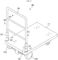
- FIG. 1 is a perspective view of an electric moving vehicle according to an example embodiment
- FIG. 2 is a diagram illustrating a configuration of an electric moving vehicle according to an example embodiment.
- FIGS. 1 and 2 an electric moving vehicle 100 according to an example embodiment is described with reference to FIGS. 1 and 2 .
- the electric moving vehicle 100 is configured to load goods to be transported and move the loaded goods, and includes a single pair of driving wheels including a left driving wheel 111a and a right driving wheel 111b provided on the left and the right, respectively, and a single pair of electric motors including a left electric motor 112a and a right electric motor 112b configured to drive the left driving wheel 111a and the right driving wheel 111b, respectively, and a body configured as a deckboard 115 configured to load goods to be transported.
- the electric moving vehicle 100 further includes a grip 130 provided at one side of the body, a single pair of force detection sensors including a left force detection sensor 121 and a right force detection sensor 122 provided between a lower portion of left and right ends of the grip 130 and an upper portion of the deckboard 115 and configured to detect a force transferred from the user to the body through the grip 130, and a controller 140 configured to control driving of the left electric motor 112a and the right electric motor 112b based on the force transferred to the body.
- a grip 130 provided at one side of the body
- a single pair of force detection sensors including a left force detection sensor 121 and a right force detection sensor 122 provided between a lower portion of left and right ends of the grip 130 and an upper portion of the deckboard 115 and configured to detect a force transferred from the user to the body through the grip 130
- a controller 140 configured to control driving of the left electric motor 112a and the right electric motor 112b based on the force transferred to the body.
- the electric moving vehicle 100 may basically include a chargeable battery.
- the battery may supply power required for the electric moving vehicle 100, including driving of the left electric motor 112a and the right electric motor 112b under control of the controller 140.
- the electric moving vehicle 100 may move desired goods to a desired location conveniently in such a manner that the goods to be transported are loaded on the deckboard 115 of the body and the left driving wheel 111a and the right driving wheel 111b are driven by the left electric motor 112a and the right electric motor 112b, respectively.
- the grip 130 holdable by the user may be provided on one side of the body. Accordingly, the user may apply a force in a direction in which the goods are to be transported with holding the grip 130 of the electric moving vehicle 100.
- the force detection sensors including the left and right force detection sensors 121 and 122 may be provided between the left and right ends of the grip 130.
- each of the left force detection sensor 121 and the right force detection sensor 122 may detect the force applied by the user to the grip 130 and transferred to the body.
- the left and right force detection sensors 121 and 122 may include a loadcell.
- a variety of sensors capable of measuring a force such as a strain gauge, may be used.
- the left force detection sensor 121 and the right force detection sensor 122 may be provided on the left and the right, respectively, at one upper side of the deckboard 115 on which goods to be transported are to be loaded. Accordingly, the left and right force detection sensors 121 and 122 may accurately and effectively detect the force applied by the user to the grip 130 and transferred to the body.
- a single pair of force detection sensors including the left force detection sensor 121 and the right force detection sensor 122 are provided between the left and right ends of the grip 130 and the deckboard 115 instead of being provided at an upper end of the grip 13, such that the user may control the electric moving vehicle 100 based on not a fixed location of the grip 130 but a location convenient for the user.
- the single pair of force detection sensors may include the left force detection sensor 121 configured to detect a force transferred to the left end of the grip 130 and the right force detection sensor 122 configured to detect a force transferred to the right end of the grip 130 from the force applied by the user.
- the single pair of force detection sensors including the left and right force detection sensors 121 and 122 may be present in a path through which the force applied by the user is transferred, and may detect the force applied by the user.
- the electric moving vehicle 100 may detect the force applied by the user, which enables the user to easily operate the electric moving vehicle 100.
- FIG. 3 illustrates an example of a process of transferring a force applied by a user in an electric moving vehicle according to an example embodiment.
- a portion of the force applied by the user may be applied to the left, for example, direction (D), of the body through the left end of the grip 130 and the left force detection sensor 121 (direction (B)).
- a portion of the force applied by the user may be applied to the right, for example, direction (E), of the body through the right end of the grip 130 and the right force detection sensor 122 (direction (C)).
- the electric moving vehicle 100 may amplify a magnitude of the force transferred to the body and may control operations of the left and right electric motors 112a and 112b to drive the electric moving vehicle 100. Accordingly, although heavy goods are loaded, the user may easily control the electric moving vehicle 100 to move the loaded goods to a desired location.
- the electric moving vehicle 100 may include the controller 140 configured to control driving of the left and right electric motors 112a and 112b based on sensing data generated at the left and right force detection sensors 121 and 122.
- the controller 140 may be provided to the body. However, it is only an example and thus, without being limited thereto, the controller 140 may be provided to, for example, the grip 130. In addition, the controller 140 may be provided at any locations at which the controller 140 may appropriately operate.
- the controller 140 may amplify a magnitude of the force transferred to the body and control the electric motors 112a and 112b.
- a brushless DC (BLDC) motor may be used for an electric motor, such as the left electric motor 112a and the right electric motor 112b in the electric moving vehicle 100.
- any motors that enable the controller 140 to control the electric moving vehicle 100 to appropriately operate may be applied.
- the controller 140 controls current applied to the left and right electric motors 112a and 112b based on sensing data generated at the left and right force detection sensors 121 and 122, the user may intuitively and easily control the electric moving vehicle 100 to move.
- the controller 140 performs a current control in controlling driving of the left and right electric motors 112a and 112b, torque, that is, a rotational force, of the left and right electric motors 112a and 112b may occur to be proportional to the current applied to the left and right electric motors 112a and 112b. Accordingly, the user may easily control the electric moving vehicle 100 to move even using a small amount of force.
- the controller 140 may use a pulse width modulation (PWM) signal having various duties to control the current applied to the left and right electric motors 112a and 112b. That is, the controller 140 of the electric moving vehicle 100 may effectively control the current applied to the left and right electric motors 112a and 112b using the PWM signal.
- PWM pulse width modulation
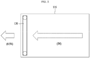
- FIGS. 4 through 6 illustrate examples of a process of driving an electric moving vehicle based on a force applied by a user in then electric moving vehicle according to an example embodiment.
- the force applied by the user may be divided into half and a half of the force may be applied to the left of the body through the left end of the grip 130 and the left force detection sensor 121. Also, another half of the force may be applied to the right of the body through the right end of the grip 130 and the right force detection sensor 122.
- each of the left force detection sensor 121 and the right force detection sensor 122 may detect a force of 0.5N.
- the controller 140 may amplify a magnitude of the force transferred to the body, that is, amplify the force of IN to 10 N, while maintaining a driving direction of the electric moving vehicle 100 based on the force, for example, 0.5N, detected at each of the left force detection sensor 121 and the right force detection sensor 122, and may control current that is applied to the left electric motor 112a and the right electric motor 112b. Accordingly, the same magnitude of current may be applied to each of the left electric motor 112a and the right electric motor 112b.
- each of the left force detection sensor 121 and the right force detection sensor 122 may detect a force of 0.25N. Accordingly, the controller 140 may amplify a magnitude of the force transferred to the body, that is, amplify the force of 0.5N to 5N, while maintaining a driving direction of the electric moving vehicle 100 based on the force, for example, 0.25N, detected at each of the left force detection sensor 121 and the right force detection sensor 122, and may control current that is applied to the left electric motor 112a and the right electric motor 112b.
- the force applied by the user may be amplified using various methods, for example, a method of changing an amplification ratio based on an input force and a method of driving the electric moving vehicle 100 based on a preset magnitude of force, instead of applying a preset amplification ratio.
- the controller 140 may amplify a magnitude of the force applied by the user and transferred to the body while maintaining a driving direction of the electric moving vehicle 100 by the force, and may control operations of the left and right electric motors 112a and 112b. Accordingly, the user may steer the electric moving vehicle 100 in a desired direction or may control the electric moving vehicle 100 to move in an intended direction.
- the force applied by the user may be divided at a predetermined ratio based on a corresponding direction and a portion of the force may be applied to the left of the body through the left end of the grip 130 and the left force detection sensor 121 and a remaining thereof may be applied to the right of the body through the right end of the grip 130 and the right force detection sensor 122.
- the controller 140 may control current that is to be applied to the left electric motor 112a and the right electric motor 112b based on the force detected at the left force detection sensor 121 and the right force detection sensor 122, respectively.
- the controller 140 may control the current of the left electric motor 112a and the right electric motor 112b to amplify the force of a[N] so that a force of 10a[N] may be generated at the left driving wheel 111a and to amplify the force of b[N] so that a force of 10b[N] may be generated at the right driving wheel 111b.
- the controller 140 may amplify a magnitude of force finally applied by the user and transferred to the body to become 10N while maintaining a driving direction of the electric moving vehicle 100 by the force applied by the user and transferred to the body. Accordingly, the user may steer the electric moving vehicle 100 in a desired direction or may control the electric moving vehicle 100 to move in an intended direction.
- the aforementioned electric moving vehicle 100 is provided as an example only. Any type of electric moving vehicles operating with a battery may be included in an application target of the example embodiment.
- the first/second force detection sensor 121, 122 such as a loadcell, configured to electrically measure a force may measure a force transferred using an analog voltage signal.
- a zero point of the first/second force detection sensor 121, 122 may frequency change due to various external factors by a sensor characteristic.
- a calibration operation of newly setting the zero point of the first/second force detection sensor 121, 122 needs to be performed prior to using the electric moving vehicle 100.
- a method of initially powering on the electric moving vehicle 100 and then performing a calibration right before driving the electric moving vehicle 100 may be employed.
- the user since the user is present adjacent to the electric moving vehicle 100, the user may act as the external interference factor of calibration by, for example, holding the grip 130 or leaning against the body.
- the electric moving vehicle 100 may be located in an activity space of a person right before the electric moving vehicle 100 is used. Accordingly, the electric moving vehicle 100 may be easily exposed to other random interference factors.
- the left force detection sensor 121 and the right force detection sensor 122 are used to control the left electric motor 112a and the right electric motor 112b, respectively. Accordingly, even a small error in a zero point may cause a serious risk. For example, if the user manipulates the electric moving vehicle 100 in a state in which a zero point error is present, a situation unintended by the user, such as a sudden unintended acceleration, may arise.
- the aforementioned method of initially powering on a target and then immediately performing the calibration may be inappropriate for the electric moving vehicle 100 in which the user is highly likely to cause a zero point error and a risk by the zero point error is great.
- a calibration algorithm capable of maximally avoiding an external interference factor with respect to a force detection sensor, for example, the first and the second force detection sensors 121 and 122, applied to the electric moving vehicle 100 and minimizing the zero point error.
- FIG. 7 is a diagram illustrating a configuration of components includable in a calibration apparatus according to an example embodiment.
- FIG. 7 illustrates a calibration apparatus 700 of an electric moving vehicle.
- the calibration apparatus 700 is a component included in the electric moving vehicle.
- the electric moving vehicle is configured using a method of controlling an electronic motor configured to amplify a magnitude of a force transferred to a body and to drive a wheel.
- a calibration operation of setting a zero point of a sensor configured to detect the force transferred to the body is required.
- the calibration apparatus 700 may include a force detection sensor 120, a controller 140, a storage 150, and an input/output (I/O) device 160.
- components of the calibration apparatus 700 may be selectively included or excluded from the calibration apparatus 700.
- the force detection sensor 120 may detect a force transferred to the body of the electric moving vehicle.
- the force detection sensor 120 may include a loadcell, a strain gauge, and the like, and may measure an amount of force applied to the electric moving vehicle through such a sensor.
- the force detection sensor 120 may correspond to the left/right force detection sensor 121, 122 of FIGS. 1 and 2 .
- the controller 140 may perform the processor functionality of performing basic arithmetic operations, logic operations, and I/O operations, and may be configured to process instructions of a computer program.
- the instructions may be provided to the controller 140 by way of the storage 150 included as a component of the electric moving vehicle.
- the controller 140 may be configured to execute an instruction received according to a program code stored in the storage 150.
- the controller 140 of FIG. 7 corresponds to the controller 140 of FIGS. 1 and 2 and may control driving of the electric motor 110 to move the electric moving vehicle based on a force transferred from the user to the electric moving vehicle.
- the controller 140 may perform a calibration operation of setting a zero point of the force detection sensor 120.
- the calibration operation will be further described.
- the storage 150 refers to a computer-readable recording medium and may include a permanent mass storage device, for example, random access memory (RAM), read only memory (ROM), and a disk drive. Also, an operating system (OS) and at least one program code, for example, a code for an application installed and executed on the electric moving vehicle, may be stored on the storage 150. Such software components may be loaded from other computer-readable recording media separate from the storage 150.
- the other computer-readable recording media may include, for example, a floppy drive, a disc, a tape, DVD/CD-ROM drive, and a memory card.
- the storage 150 may store and maintain data associated with a calibration of the force detection sensor 120.
- the storage 150 may store an initial setting value, for example, a factory value, about a zero point of the force detection sensor 120 and may store sensing data that is measured during a calibration process and final data that is set as the zero point.
- the I/O device 160 may be a device for interface between the electric moving vehicle and the user.
- an input device may include a device, such as a keyboard and a mouse
- an output device may include a device, such as a light emitting diode (LED) and a display.
- the I/O device 160 may be a device in which an input function and an output function are integrated, such as a touchscreen.
- the controller 140 may display information associated with calibration and may receive a user instruction associated with the calibration through the I/O device 160 in processing an instruction of the computer program loaded to the storage 150.
- FIG. 8 is a flowchart illustrating an example of a calibration method of an electric moving vehicle performed by a calibration apparatus according to an example embodiment.
- the calibration method may be performed by the controller 140 of the electric moving vehicle of FIG. 7 .
- the controller 140 may determine whether charging of the electric moving vehicle using a battery starts. If an electric plug or a charging cable is connected to the electric moving vehicle, the controller 140 may recognize that the charging starts.
- the electric plug or the charging cable may be connected to the electric moving vehicle during charging of the electric moving vehicle.
- the electric moving vehicle may be present in an environment in which an operation intent of the user and an external interference factor are minimized.
- the controller 140 may collect a sensing value of the force detection sensor 120 that detects a force applied to the electric moving vehicle at desired intervals, and may store the collected sensing values in the storage 150.
- the controller 140 may measure a zero point of the force detection sensor 120 at the same time intervals, for example, every 15 minutes or 20 minutes, during an entire period of time after charging of the electric moving vehicle starts.
- the controller 140 may measure a zero point of the force detection sensor 120 at intervals of a first time during a specific period of time after charging of the electric moving vehicle starts and may measure the zero point of the force detection sensor 120 at intervals of a second time different from the first time during a remaining period of time.
- the controller 140 may collect a sensing value of the force detection sensor 120 intermittently, for example, every 1 hour during 2 hours right after charging starts and may collect the sensing value of the force detection sensor 120 relatively further frequently, for example, every 20 minutes after 2 hours elapses.
- the controller 140 may remove noise in the sensing values of the force detection sensor 120 collected at desired intervals using a low pass filter and may store the noise-removed sensing values.
- the controller 140 may determine whether charging of the electric moving vehicle is completed. If the battery of the electric moving vehicle is fully charged or if the electric plug or the charging cable is disconnected from the electric moving vehicle, the controller 140 may recognize that charging of the electric moving vehicle is completed.
- the controller 140 may set the zero point of the force detection sensor 120 based on the sensing values stored at desired intervals during the charging process.
- the controller 140 may collect the sensing value of the force detection sensor 120 at desired intervals until charging of the electric moving vehicle is completed and may set the zero point of the force detection sensor 120 based on the collected sensing values.
- the zero point of the force detection sensor 120 may be set at a point in time sufficient for calibration after charging of the electric moving vehicle starts, for example, at a point in time at which a preset period of time, for example, 2 hours elapses.
- the calibration apparatus of the electric moving vehicle may perform the calibration of the force detection sensor 120 during charging of the electric moving vehicle, thereby preventing an effect by a potential external interference factor.
- FIG. 9 is a flowchart illustrating an example of operation S840 of setting a zero point of a force detection sensor according to example embodiment.
- the controller 140 may determine whether a number of sensing values stored during charging of the electric moving vehicle is greater than or equal to a threshold. That is, if a sufficient number of sensing values of the force detection sensor 120 are not collected due to a lack of a charging time for the electric moving vehicle, whether a sufficient number of sensing values for the calibration are secured may need to be verified.
- the controller 140 may set the zero point of the force detection sensor 120 using a majority value that most frequently appears among the stored sensing values. That is, the controller 140 may set, as the zero point of the force detection sensor 120, a sensing value corresponding to a majority value among the stored sensing values by applying a majority filter. As another example, the controller 140 may average remaining sensing values excluding a maximum value and a minimum value from among the sensing values stored during charging of the electric moving vehicle and may set the average value as the zero point of the force detection sensor 120.
- the controller 140 may process sensing values having a difference therebetween within a desired range as a single sensing value. That is, the controller 140 may regard and process sensing values having an insignificant difference therebetween as the same value.
- the controller 140 may determine whether the sensing value set as the zero point of the force detection sensor 120 is within a preset setting range.
- the setting range is a reference used to determine a reliability of the zero point and may be determined using ⁇ range values based on an initial setting value, for example, a factory value, about the zero point of the force detection sensor 120. That is, the controller 140 may determine a reliability of a sensing value set as the zero point of the force detection sensor 120 and may terminate the calibration if the sensing value set as the zero point of the force detection sensor 120 is included in a reliable range.
- the controller 140 may set the zero point of the force detection sensor 120 using an initial setting value preset for the zero point of the force detection sensor 120 or a sensing value that is previously set as the zero point in operation S944.
- the controller 140 may set the zero point of the force detection sensor 120 by applying the majority filter to the sensing values stored during charging of the electric moving vehicle. If a sufficient number of measurement values of sensing values of the force detection sensor 120 are not collected due to a lack of a charging time for the electric moving vehicle or if the sensing value set as the zero point of the force detection sensor 120 is outside the reliable range, the controller 140 may reuse the initial setting value of the force detection sensor 120 or a most recently secured reliable zero point.
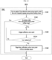
- FIG. 10 is a flowchart illustrating another example of operation S840 of setting a zero point of a force detection sensor according to example embodiment.
- the controller 140 may set a zero point of the force detection sensor 120 using a majority value that most frequently appears among sensing values stored during charging of the electric moving vehicle. That is, the controller 140 may set, as the zero point of the force detection sensor 120, a sensing value corresponding to a majority value among the sensing values stored during charging by applying the majority filter. As another example, the controller 140 may average remaining sensing values excluding a maximum value and a minimum value among the sensing values stored during charging of the electric moving vehicle and may set the average value as the zero point of the force detection sensor 120.
- the controller 140 may determine whether the sensing value set as the zero point of the force detection sensor 120 is within a preset setting range.
- the setting range is a reference used to determine a reliability of the zero point and may be determined using ⁇ range values based on an initial setting value that is preset for the zero point of the force detection sensor 120. That is, the controller 140 may determine a reliability of a sensing value set as the zero point of the force detection sensor 120 and may terminate the calibration if the sensing value set as the zero point of the force detection sensor 120 is included in a reliable range.
- the controller 140 may determine that a malfunction issue has occurred during the calibration process and may enter an emergency mode and output a calibration error alert corresponding to the emergency mode through the I/O device 160 in operation S1043. For example, if the calibration is performed during charging in a state in which a predetermined force is applied to the electric moving vehicle, such as in a state in which a clothing is hanging over a grip of the electric moving vehicle, an unreliable sensing value may be set as the zero point of the force detection sensor 120. The controller 140 may recognize a calibration error situation and may output an alert corresponding to the emergency mode.
- the controller 140 may determine whether a user instruction to the calibration error alert is input.
- the user may verify the calibration error alert output through the I/O device 160 and may recognize a situation in which a normal calibration may not be performed due to an occurrence of an external interference factor in the electric moving vehicle, for example, a clothing or an obstacle hanging over the grip.
- the user may directly remove the external interference factor from the electric moving vehicle and may request reperforming of the calibration.
- the user instruction to request reperforming of the calibration may be transferred to the controller 140 through a predetermined button among input devices of the I/O device 160 in response to the calibration error alert.
- the controller 140 may reperform the calibration of the force detection sensor 120 and may set the zero point of the force detection sensor 120. Once the user removes the external interference factor from the electric moving vehicle and requests reperforming of the calibration, the controller 140 may newly collect the sensing value of the force detection sensor 120 at desired time intervals from a point in time at which the user instruction is input and may set the zero point of the force detection sensor 120 based on the newly collected sensing values.
- the systems or apparatuses described herein may be implemented using hardware components, software components, and/or a combination thereof.
- the apparatuses and the components described herein may be implemented using one or more general-purpose or special purpose computers, such as, for example, a processor, a controller, an arithmetic logic unit (ALU), a digital signal processor, a microcomputer, a field programmable gate array (FPGA), a programmable logic unit (PLU), a microprocessor, or any other device capable of responding to and executing instructions in a defined manner.
- the processing device may run an operating system (OS) and one or more software applications that run on the OS.
- the processing device also may access, store, manipulate, process, and create data in response to execution of the software.
- OS operating system
- the processing device also may access, store, manipulate, process, and create data in response to execution of the software.
- a processing device may include multiple processing elements and/or multiple types of processing elements.
- a processing device may include multiple processors or a processor and a controller.
- different processing configurations are possible, such as parallel processors.
- the software may include a computer program, a piece of code, an instruction, or some combination thereof, for independently or collectively instructing or configuring the processing device to operate as desired.
- Software and data may be embodied permanently or temporarily in any type of machine, component, physical or virtual equipment, computer storage medium or device, or in a propagated signal wave capable of providing instructions or data to or being interpreted by the processing device.
- the software also may be distributed over network coupled computer systems so that the software is stored and executed in a distributed fashion.
- the software and data may be stored by one or more computer readable storage mediums.
- the methods according to the above-described example embodiments may be recorded in non-transitory computer-readable media including program instructions to implement various operations of the above-described example embodiments.
- the media may also include, alone or in combination with the program instructions, data files, data structures, and the like.
- the program instructions recorded on the media may be those specially designed and constructed for the purposes of example embodiments, or they may be of the kind well-known and available to those having skill in the computer software arts.
- non-transitory computer-readable media examples include magnetic media such as hard disks, floppy disks, and magnetic tapes; optical media such as CD-ROM discs, and DVDs; magneto-optical media such as floptical disks; and hardware devices that are specially configured to store and perform program instructions, such as read-only memory (ROM), random access memory (RAM), flash memory, and the like.
- program instructions include both machine code, such as produced by a compiler, and files containing higher level code that may be executed by the computer using an interpreter.
- the above-described devices may be configured to act as one or more software modules in order to perform the operations of the above-described example embodiments, or vice versa.
Landscapes
- Engineering & Computer Science (AREA)
- Transportation (AREA)
- Mechanical Engineering (AREA)
- Physics & Mathematics (AREA)
- General Physics & Mathematics (AREA)
- Chemical & Material Sciences (AREA)
- Combustion & Propulsion (AREA)
- Power Engineering (AREA)
- Electric Propulsion And Braking For Vehicles (AREA)
- Handcart (AREA)
Abstract
Description
- The following description of example embodiments relates to a calibration technology of a force detection sensor applied to an electric moving vehicle.
- Currently, moving vehicles are used to carry goods for various purposes in various fields, such as, for example, shopping malls, home delivery services, and industrial sites.
- For example, Korean Utility Model Registration NO.
20-0440927 registered on July 2, 2008 - When heavy goods are loaded on a moving vehicle, a user needs to use a considerable amount of force to move the moving vehicle. Further, it becomes more difficulty for the user to control the moving vehicle to move in a desired direction by appropriately operating the loaded moving vehicle and the user may need to experience a significant difficulty in transporting the goods.
- Accordingly, an electric moving vehicle including a motor and moving through driving of the motor is widely used.
- At least one example embodiment provides a calibration method and apparatus that may minimize a zero point error by maximally avoiding an external interference factor with respect to a force detection sensor applied to an electric moving vehicle.
- According to an aspect of at least one example embodiment, there is provided a computer-implemented calibration method including collecting a sensing value of a force detection sensor that detects a force applied to an electric moving vehicle during charging of a battery included in the electric moving vehicle; and setting a zero point of the force detection sensor based on the sensing values collected during charging of the battery.
- The setting may include setting the zero point of the force detection sensor using a majority value that most frequently appears among the collected sensing values.
- The setting may include setting the zero point of the force detection sensor using an average value of remaining sensing values excluding a maximum value and a minimum value from among the collected sensing values.
- The setting may include setting the zero point of the force detection sensor using the collected sensing values if a number of the collected sensing values is greater than or equal to a threshold; and setting the zero point of the force detection sensor using a preset initial setting value or a sensing value that is previously set as the zero point if the number of collected sensing values is less than the threshold.
- The setting may include determining a sensing value set as the zero point of the force detection sensor as a calibration error if the sensing value set as the zero point of the force detection sensor is outside a preset setting range and outputting a calibration error alert.
- The setting may include newly collecting the sensing value of the force detection sensor from a point in time at which a user instruction is input in response to the input of the user instruction for requesting reperforming of a calibration, and setting the zero point of the force detection sensor based on the newly collected sensing values.
- The setting range may be determined based on an initial setting value predetermined for the zero point of the force detection sensor as a reference used to determine a reliability of the sensing value set as the zero point of the force detection sensor.
- The collecting may include storing a noise-removed sensing value after removing noise from the sensing value of the force detection sensor using a low pass filter.
- The electric moving vehicle may be configured as a moving transportation structure on which a user is boarded.
- According to an aspect of at least one example embodiment, there is provided a calibration apparatus of an electric moving vehicle, the calibration apparatus including a force detection sensor configured to detect a force applied to the electric moving vehicle; and a controller configured to collect a sensing value of the force detection sensor during charging of a battery included in the electric moving vehicle, and to set a zero point of the force detection sensor based on the sensing values collected during charging of the battery.
- According to some example embodiments, it is possible to maximally avoid an external interference factor and to minimize a zero point error by performing a calibration of a force detection sensor during a charging process of an electric moving vehicle.
- According to some example embodiments, it is possible to enhance reliability of a zero point and to significantly reduce a risk probability by a malfunction by reusing an initial setting value or a currently secured reliable zero point if a value set as a zero point is outside a setting range.
- Further areas of applicability will become apparent from the description provided herein. The description and specific examples in this summary are intended for purposes of illustration only and are not intended to limit the scope of the present disclosure.
- These and/or other aspects, features, and advantages of the invention will become apparent and more readily appreciated from the following description of embodiments, taken in conjunction with the accompanying drawings of which:
-
FIG. 1 is a perspective view of an electric moving vehicle according to an example embodiment; -
FIG. 2 is a diagram illustrating a configuration of an electric moving vehicle according to an example embodiment; -
FIG. 3 illustrates an example of a process of transferring a force applied by a user in an electric moving vehicle according to an example embodiment; -
FIGS. 4 through 6 illustrate examples of a process of driving an electric moving vehicle based on a force applied by a user in the electric moving vehicle according to an example embodiment; -
FIG. 7 is a diagram illustrating a configuration of components includable in a calibration apparatus according to an example embodiment; -
FIG. 8 is a flowchart illustrating an example of a calibration method of an electric moving vehicle performed by a calibration apparatus according to an example embodiment; -
FIG. 9 is a flowchart illustrating an example of an operation of setting a zero point of a force detection sensor according to an example embodiment; and -
FIG. 10 is a flowchart illustrating another example of an operation of setting a zero point of a force detection sensor according to an example embodiment. - One or more example embodiments will be described in detail with reference to the accompanying drawings. Example embodiments, however, may be embodied in various different forms, and should not be construed as being limited to only the illustrated embodiments. Rather, the illustrated embodiments are provided as examples so that this disclosure will be thorough and complete, and will fully convey the concepts of this disclosure to those skilled in the art. Accordingly, known processes, elements, and techniques, may not be described with respect to some example embodiments. Unless otherwise noted, like reference characters denote like elements throughout the attached drawings and written description, and thus descriptions will not be repeated.
- Although the terms "first," "second," "third," etc., may be used herein to describe various elements, components, regions, layers, and/or sections, these elements, components, regions, layers, and/or sections, should not be limited by these terms. These terms are only used to distinguish one element, component, region, layer, or section, from another region, layer, or section. Thus, a first element, component, region, layer, or section, discussed below may be termed a second element, component, region, layer, or section, without departing from the scope of this disclosure.
- As used herein, the singular forms "a," "an," and "the," are intended to include the plural forms as well, unless the context clearly indicates otherwise. It will be further understood that the terms "comprises" and/or "comprising," when used in this specification, specify the presence of stated features, integers, steps, operations, elements, and/or components, but do not preclude the presence or addition of one or more other features, integers, steps, operations, elements, components, and/or groups, thereof. As used herein, the term "and/or" includes any and all combinations of one or more of the associated listed items.
- Unless otherwise defined, all terms (including technical and scientific terms) used herein have the same meaning as commonly understood by one of ordinary skill in the art to which example embodiments belong. Terms, such as those defined in commonly used dictionaries, should be interpreted as having a meaning that is consistent with their meaning in the context of the relevant art and/or this disclosure, and should not be interpreted in an idealized or overly formal sense unless expressly so defined herein.
- Hereinafter, example embodiments will be described with reference to the accompanying drawings.
- The example embodiments relate to a calibration method and apparatus that may minimize a zero point error by maximally avoiding an external interference factor with respect to a force detection sensor applied to an electric moving vehicle.
- The example embodiments disclosed herein may achieve many advantages in terms of reliability, safety, convenience, and cost saving, etc., of an electric moving vehicle.
- The term "electric moving vehicle" used herein may inclusively indicate a transportation device of goods and a transportation device in a structure on which a person, for example, a user is boarded. If the electric moving device is for boarding a person, the electric moving device may include, for example, an electric wheelchair, an electric moving bed, an electric stroller, and an electric wagon. Hereinafter, the example embodiments will be described using the transportation device of goods as a representative example, however, are not limited thereto.
-
FIG. 1 is a perspective view of an electric moving vehicle according to an example embodiment, andFIG. 2 is a diagram illustrating a configuration of an electric moving vehicle according to an example embodiment. - Hereinafter, an electric moving
vehicle 100 according to an example embodiment is described with reference toFIGS. 1 and2 . - Referring to
FIGS. 1 and2 , the electric movingvehicle 100 is configured to load goods to be transported and move the loaded goods, and includes a single pair of driving wheels including a leftdriving wheel 111a and a rightdriving wheel 111b provided on the left and the right, respectively, and a single pair of electric motors including a leftelectric motor 112a and a rightelectric motor 112b configured to drive the leftdriving wheel 111a and theright driving wheel 111b, respectively, and a body configured as adeckboard 115 configured to load goods to be transported. - The electric moving
vehicle 100 further includes agrip 130 provided at one side of the body, a single pair of force detection sensors including a leftforce detection sensor 121 and a rightforce detection sensor 122 provided between a lower portion of left and right ends of thegrip 130 and an upper portion of thedeckboard 115 and configured to detect a force transferred from the user to the body through thegrip 130, and acontroller 140 configured to control driving of the leftelectric motor 112a and the rightelectric motor 112b based on the force transferred to the body. - Although not illustrated in detail, the electric moving
vehicle 100 may basically include a chargeable battery. Here, the battery may supply power required for the electric movingvehicle 100, including driving of the leftelectric motor 112a and the rightelectric motor 112b under control of thecontroller 140. - According to the above configuration, the electric moving
vehicle 100 may move desired goods to a desired location conveniently in such a manner that the goods to be transported are loaded on thedeckboard 115 of the body and the leftdriving wheel 111a and the right drivingwheel 111b are driven by the leftelectric motor 112a and the rightelectric motor 112b, respectively. - In the electric moving
vehicle 100, thegrip 130 holdable by the user may be provided on one side of the body. Accordingly, the user may apply a force in a direction in which the goods are to be transported with holding thegrip 130 of the electric movingvehicle 100. - In the electric moving
vehicle 100, the force detection sensors including the left and rightforce detection sensors grip 130. Here, each of the leftforce detection sensor 121 and the rightforce detection sensor 122 may detect the force applied by the user to thegrip 130 and transferred to the body. Here, the left and rightforce detection sensors - Referring to
FIG. 1 , the leftforce detection sensor 121 and the rightforce detection sensor 122 may be provided on the left and the right, respectively, at one upper side of thedeckboard 115 on which goods to be transported are to be loaded. Accordingly, the left and rightforce detection sensors grip 130 and transferred to the body. - In the aforementioned
electric moving vehicle 100, a single pair of force detection sensors including the leftforce detection sensor 121 and the rightforce detection sensor 122 are provided between the left and right ends of thegrip 130 and thedeckboard 115 instead of being provided at an upper end of the grip 13, such that the user may control the electric movingvehicle 100 based on not a fixed location of thegrip 130 but a location convenient for the user. - In detail, the single pair of force detection sensors may include the left
force detection sensor 121 configured to detect a force transferred to the left end of thegrip 130 and the rightforce detection sensor 122 configured to detect a force transferred to the right end of thegrip 130 from the force applied by the user. Accordingly, in the electric movingvehicle 100, the single pair of force detection sensors including the left and rightforce detection sensors vehicle 100 may detect the force applied by the user, which enables the user to easily operate the electric movingvehicle 100. -
FIG. 3 illustrates an example of a process of transferring a force applied by a user in an electric moving vehicle according to an example embodiment. - Hereinafter, operations of the left and right
force detection sensors FIG. 3 . - Referring to
FIG. 3 , if the user applies a force in a direction, for example, direction (A), in which loaded goods are to be transported with holding thegrip 130 using a single hand or both hands, a portion of the force applied by the user may be applied to the left, for example, direction (D), of the body through the left end of thegrip 130 and the left force detection sensor 121 (direction (B)). Also, a portion of the force applied by the user may be applied to the right, for example, direction (E), of the body through the right end of thegrip 130 and the right force detection sensor 122 (direction (C)). - According to an example embodiment, while maintaining a driving direction of the electric moving
vehicle 100 by a force applied by the user to thegrip 130 and transferred to the body, the electric movingvehicle 100 may amplify a magnitude of the force transferred to the body and may control operations of the left and rightelectric motors vehicle 100. Accordingly, although heavy goods are loaded, the user may easily control the electric movingvehicle 100 to move the loaded goods to a desired location. - The electric moving
vehicle 100 may include thecontroller 140 configured to control driving of the left and rightelectric motors force detection sensors controller 140 may be provided to the body. However, it is only an example and thus, without being limited thereto, thecontroller 140 may be provided to, for example, thegrip 130. In addition, thecontroller 140 may be provided at any locations at which thecontroller 140 may appropriately operate. - While maintaining a driving direction of the electric moving
vehicle 100 by a force applied by the user to thegrip 130 and transferred to the body, thecontroller 140 may amplify a magnitude of the force transferred to the body and control theelectric motors electric motor 112a and the rightelectric motor 112b in the electric movingvehicle 100. In addition, any motors that enable thecontroller 140 to control the electric movingvehicle 100 to appropriately operate may be applied. - Since the
controller 140 controls current applied to the left and rightelectric motors force detection sensors vehicle 100 to move. Here, if thecontroller 140 performs a current control in controlling driving of the left and rightelectric motors electric motors electric motors vehicle 100 to move even using a small amount of force. Thecontroller 140 may use a pulse width modulation (PWM) signal having various duties to control the current applied to the left and rightelectric motors controller 140 of the electric movingvehicle 100 may effectively control the current applied to the left and rightelectric motors -
FIGS. 4 through 6 illustrate examples of a process of driving an electric moving vehicle based on a force applied by a user in then electric moving vehicle according to an example embodiment. - Referring to
FIG. 4 , if the user vertically applies a force to thegrip 130 to make the electric movingvehicle 100 move forward, for example, if the user applies a force of IN, the force applied by the user may be divided into half and a half of the force may be applied to the left of the body through the left end of thegrip 130 and the leftforce detection sensor 121. Also, another half of the force may be applied to the right of the body through the right end of thegrip 130 and the rightforce detection sensor 122. Here, each of the leftforce detection sensor 121 and the rightforce detection sensor 122 may detect a force of 0.5N. Accordingly, thecontroller 140 may amplify a magnitude of the force transferred to the body, that is, amplify the force of IN to 10 N, while maintaining a driving direction of the electric movingvehicle 100 based on the force, for example, 0.5N, detected at each of the leftforce detection sensor 121 and the rightforce detection sensor 122, and may control current that is applied to the leftelectric motor 112a and the rightelectric motor 112b. Accordingly, the same magnitude of current may be applied to each of the leftelectric motor 112a and the rightelectric motor 112b. - Referring to
FIG. 5 , if the user applies a force to thegrip 130 in a pulling direction to make the electric movingvehicle 100 slowly move backward, for example, if the user applies a force of 0.5N, each of the leftforce detection sensor 121 and the rightforce detection sensor 122 may detect a force of 0.25N. Accordingly, thecontroller 140 may amplify a magnitude of the force transferred to the body, that is, amplify the force of 0.5N to 5N, while maintaining a driving direction of the electric movingvehicle 100 based on the force, for example, 0.25N, detected at each of the leftforce detection sensor 121 and the rightforce detection sensor 122, and may control current that is applied to the leftelectric motor 112a and the rightelectric motor 112b. - According to an example embodiment, in the case of driving the electric moving
vehicle 100 by amplifying a force applied by the user, the force applied by the user may be amplified using various methods, for example, a method of changing an amplification ratio based on an input force and a method of driving the electric movingvehicle 100 based on a preset magnitude of force, instead of applying a preset amplification ratio. - Further, referring to
FIG. 6 , in the electric movingvehicle 100 according to an example embodiment, although the user applies a force in a direction inclined relative to a forward/backward direction, thecontroller 140 may amplify a magnitude of the force applied by the user and transferred to the body while maintaining a driving direction of the electric movingvehicle 100 by the force, and may control operations of the left and rightelectric motors vehicle 100 in a desired direction or may control the electric movingvehicle 100 to move in an intended direction. - In detail, referring to
FIG. 6 , if the user applies a force to thegrip 130 in a desired direction, for example, applies a force of IN, the force applied by the user may be divided at a predetermined ratio based on a corresponding direction and a portion of the force may be applied to the left of the body through the left end of thegrip 130 and the leftforce detection sensor 121 and a remaining thereof may be applied to the right of the body through the right end of thegrip 130 and the rightforce detection sensor 122. Here, if the leftforce detection sensor 121 detects a force of a[N] and the rightforce detection sensor 122 detects a force of b[N], thecontroller 140 may control current that is to be applied to the leftelectric motor 112a and the rightelectric motor 112b based on the force detected at the leftforce detection sensor 121 and the rightforce detection sensor 122, respectively. - For example, the
controller 140 may control the current of the leftelectric motor 112a and the rightelectric motor 112b to amplify the force of a[N] so that a force of 10a[N] may be generated at theleft driving wheel 111a and to amplify the force of b[N] so that a force of 10b[N] may be generated at theright driving wheel 111b. Thecontroller 140 may amplify a magnitude of force finally applied by the user and transferred to the body to become 10N while maintaining a driving direction of the electric movingvehicle 100 by the force applied by the user and transferred to the body. Accordingly, the user may steer the electric movingvehicle 100 in a desired direction or may control the electric movingvehicle 100 to move in an intended direction. - The aforementioned
electric moving vehicle 100 is provided as an example only. Any type of electric moving vehicles operating with a battery may be included in an application target of the example embodiment. - Hereinafter, example embodiments of a calibration algorithm of a force detection sensor, for example, the first
force detection sensor 121 and the secondforce detection sensor 122, will be further described. - The first/second
force detection sensor force detection sensor - Accordingly, a calibration operation of newly setting the zero point of the first/second
force detection sensor vehicle 100. In general, a method of initially powering on the electric movingvehicle 100 and then performing a calibration right before driving the electric movingvehicle 100 may be employed. In this case, since the user is present adjacent to the electric movingvehicle 100, the user may act as the external interference factor of calibration by, for example, holding thegrip 130 or leaning against the body. Also, in many cases, the electric movingvehicle 100 may be located in an activity space of a person right before the electric movingvehicle 100 is used. Accordingly, the electric movingvehicle 100 may be easily exposed to other random interference factors. - In the electric moving
vehicle 100, the leftforce detection sensor 121 and the rightforce detection sensor 122 are used to control the leftelectric motor 112a and the rightelectric motor 112b, respectively. Accordingly, even a small error in a zero point may cause a serious risk. For example, if the user manipulates the electric movingvehicle 100 in a state in which a zero point error is present, a situation unintended by the user, such as a sudden unintended acceleration, may arise. - The aforementioned method of initially powering on a target and then immediately performing the calibration may be inappropriate for the electric moving
vehicle 100 in which the user is highly likely to cause a zero point error and a risk by the zero point error is great. - Accordingly, proposed herein is a calibration algorithm capable of maximally avoiding an external interference factor with respect to a force detection sensor, for example, the first and the second
force detection sensors vehicle 100 and minimizing the zero point error. -
FIG. 7 is a diagram illustrating a configuration of components includable in a calibration apparatus according to an example embodiment. -
FIG. 7 illustrates acalibration apparatus 700 of an electric moving vehicle. Here, thecalibration apparatus 700 is a component included in the electric moving vehicle. - The electric moving vehicle is configured using a method of controlling an electronic motor configured to amplify a magnitude of a force transferred to a body and to drive a wheel. Here, a calibration operation of setting a zero point of a sensor configured to detect the force transferred to the body is required.
- Referring to
FIG. 7 , thecalibration apparatus 700 may include aforce detection sensor 120, acontroller 140, astorage 150, and an input/output (I/O)device 160. Depending on example embodiments, components of thecalibration apparatus 700 may be selectively included or excluded from thecalibration apparatus 700. - The
force detection sensor 120 may detect a force transferred to the body of the electric moving vehicle. For example, theforce detection sensor 120 may include a loadcell, a strain gauge, and the like, and may measure an amount of force applied to the electric moving vehicle through such a sensor. Here, theforce detection sensor 120 may correspond to the left/rightforce detection sensor FIGS. 1 and2 . - The
controller 140 may perform the processor functionality of performing basic arithmetic operations, logic operations, and I/O operations, and may be configured to process instructions of a computer program. The instructions may be provided to thecontroller 140 by way of thestorage 150 included as a component of the electric moving vehicle. For example, thecontroller 140 may be configured to execute an instruction received according to a program code stored in thestorage 150. - The
controller 140 ofFIG. 7 corresponds to thecontroller 140 ofFIGS. 1 and2 and may control driving of the electric motor 110 to move the electric moving vehicle based on a force transferred from the user to the electric moving vehicle. In particular, thecontroller 140 may perform a calibration operation of setting a zero point of theforce detection sensor 120. Hereinafter, the calibration operation will be further described. - The
storage 150 refers to a computer-readable recording medium and may include a permanent mass storage device, for example, random access memory (RAM), read only memory (ROM), and a disk drive. Also, an operating system (OS) and at least one program code, for example, a code for an application installed and executed on the electric moving vehicle, may be stored on thestorage 150. Such software components may be loaded from other computer-readable recording media separate from thestorage 150. The other computer-readable recording media may include, for example, a floppy drive, a disc, a tape, DVD/CD-ROM drive, and a memory card. - The
storage 150 may store and maintain data associated with a calibration of theforce detection sensor 120. Here, thestorage 150 may store an initial setting value, for example, a factory value, about a zero point of theforce detection sensor 120 and may store sensing data that is measured during a calibration process and final data that is set as the zero point. - The I/
O device 160 may be a device for interface between the electric moving vehicle and the user. For example, an input device may include a device, such as a keyboard and a mouse, and an output device may include a device, such as a light emitting diode (LED) and a display. As another example, the I/O device 160 may be a device in which an input function and an output function are integrated, such as a touchscreen. In detail, for example, thecontroller 140 may display information associated with calibration and may receive a user instruction associated with the calibration through the I/O device 160 in processing an instruction of the computer program loaded to thestorage 150. -
FIG. 8 is a flowchart illustrating an example of a calibration method of an electric moving vehicle performed by a calibration apparatus according to an example embodiment. The calibration method may be performed by thecontroller 140 of the electric moving vehicle ofFIG. 7 . - Referring to
FIG. 8 , in operation S810, thecontroller 140 may determine whether charging of the electric moving vehicle using a battery starts. If an electric plug or a charging cable is connected to the electric moving vehicle, thecontroller 140 may recognize that the charging starts. The electric plug or the charging cable may be connected to the electric moving vehicle during charging of the electric moving vehicle. Thus, the electric moving vehicle may be present in an environment in which an operation intent of the user and an external interference factor are minimized. - In operation S820, once charging of the electric moving vehicle starts, the
controller 140 may collect a sensing value of theforce detection sensor 120 that detects a force applied to the electric moving vehicle at desired intervals, and may store the collected sensing values in thestorage 150. For example, thecontroller 140 may measure a zero point of theforce detection sensor 120 at the same time intervals, for example, every 15 minutes or 20 minutes, during an entire period of time after charging of the electric moving vehicle starts. As another example, thecontroller 140 may measure a zero point of theforce detection sensor 120 at intervals of a first time during a specific period of time after charging of the electric moving vehicle starts and may measure the zero point of theforce detection sensor 120 at intervals of a second time different from the first time during a remaining period of time. In detail, thecontroller 140 may collect a sensing value of theforce detection sensor 120 intermittently, for example, every 1 hour during 2 hours right after charging starts and may collect the sensing value of theforce detection sensor 120 relatively further frequently, for example, every 20 minutes after 2 hours elapses. Here, thecontroller 140 may remove noise in the sensing values of theforce detection sensor 120 collected at desired intervals using a low pass filter and may store the noise-removed sensing values. - In operation S830, the
controller 140 may determine whether charging of the electric moving vehicle is completed. If the battery of the electric moving vehicle is fully charged or if the electric plug or the charging cable is disconnected from the electric moving vehicle, thecontroller 140 may recognize that charging of the electric moving vehicle is completed. - In operation S840, once charging of the electric moving vehicle is completed, the
controller 140 may set the zero point of theforce detection sensor 120 based on the sensing values stored at desired intervals during the charging process. Thecontroller 140 may collect the sensing value of theforce detection sensor 120 at desired intervals until charging of the electric moving vehicle is completed and may set the zero point of theforce detection sensor 120 based on the collected sensing values. - Although the description is made based on an example in which the zero point of the
force detection sensor 120 is set at a point in time at which charging is completed, it is provided as an example only. For example, the zero point of theforce detection sensor 120 may be set at a point in time sufficient for calibration after charging of the electric moving vehicle starts, for example, at a point in time at which a preset period of time, for example, 2 hours elapses. - Accordingly, the calibration apparatus of the electric moving vehicle may perform the calibration of the
force detection sensor 120 during charging of the electric moving vehicle, thereby preventing an effect by a potential external interference factor. -
FIG. 9 is a flowchart illustrating an example of operation S840 of setting a zero point of a force detection sensor according to example embodiment. - Referring to
FIG. 9 , in operation S941, thecontroller 140 may determine whether a number of sensing values stored during charging of the electric moving vehicle is greater than or equal to a threshold. That is, if a sufficient number of sensing values of theforce detection sensor 120 are not collected due to a lack of a charging time for the electric moving vehicle, whether a sufficient number of sensing values for the calibration are secured may need to be verified. - In operation S942, if the number of sensing values stored during charging of the electric moving vehicle is greater than or equal to the threshold, the
controller 140 may set the zero point of theforce detection sensor 120 using a majority value that most frequently appears among the stored sensing values. That is, thecontroller 140 may set, as the zero point of theforce detection sensor 120, a sensing value corresponding to a majority value among the stored sensing values by applying a majority filter. As another example, thecontroller 140 may average remaining sensing values excluding a maximum value and a minimum value from among the sensing values stored during charging of the electric moving vehicle and may set the average value as the zero point of theforce detection sensor 120. Here, thecontroller 140 may process sensing values having a difference therebetween within a desired range as a single sensing value. That is, thecontroller 140 may regard and process sensing values having an insignificant difference therebetween as the same value. - In operation S943, the
controller 140 may determine whether the sensing value set as the zero point of theforce detection sensor 120 is within a preset setting range. Here, the setting range is a reference used to determine a reliability of the zero point and may be determined using ± range values based on an initial setting value, for example, a factory value, about the zero point of theforce detection sensor 120. That is, thecontroller 140 may determine a reliability of a sensing value set as the zero point of theforce detection sensor 120 and may terminate the calibration if the sensing value set as the zero point of theforce detection sensor 120 is included in a reliable range. - If the number of sensing values stored during charging of the electric moving vehicle is determined to be less than the threshold in operation S941 or if the number of sensing values set as the zero point of the
force detection sensor 120 is determined to be outside the preset setting range in operation S943, thecontroller 140 may set the zero point of theforce detection sensor 120 using an initial setting value preset for the zero point of theforce detection sensor 120 or a sensing value that is previously set as the zero point in operation S944. - Accordingly, the
controller 140 may set the zero point of theforce detection sensor 120 by applying the majority filter to the sensing values stored during charging of the electric moving vehicle. If a sufficient number of measurement values of sensing values of theforce detection sensor 120 are not collected due to a lack of a charging time for the electric moving vehicle or if the sensing value set as the zero point of theforce detection sensor 120 is outside the reliable range, thecontroller 140 may reuse the initial setting value of theforce detection sensor 120 or a most recently secured reliable zero point. -
FIG. 10 is a flowchart illustrating another example of operation S840 of setting a zero point of a force detection sensor according to example embodiment. - Referring to
FIG. 10 , in operation S1041, thecontroller 140 may set a zero point of theforce detection sensor 120 using a majority value that most frequently appears among sensing values stored during charging of the electric moving vehicle. That is, thecontroller 140 may set, as the zero point of theforce detection sensor 120, a sensing value corresponding to a majority value among the sensing values stored during charging by applying the majority filter. As another example, thecontroller 140 may average remaining sensing values excluding a maximum value and a minimum value among the sensing values stored during charging of the electric moving vehicle and may set the average value as the zero point of theforce detection sensor 120. - In operation S1042, the
controller 140 may determine whether the sensing value set as the zero point of theforce detection sensor 120 is within a preset setting range. Here, the setting range is a reference used to determine a reliability of the zero point and may be determined using ± range values based on an initial setting value that is preset for the zero point of theforce detection sensor 120. That is, thecontroller 140 may determine a reliability of a sensing value set as the zero point of theforce detection sensor 120 and may terminate the calibration if the sensing value set as the zero point of theforce detection sensor 120 is included in a reliable range. - If the sensing value set as the zero point of the
force detection sensor 120 is determined to be outside the preset setting range in operation S1042, thecontroller 140 may determine that a malfunction issue has occurred during the calibration process and may enter an emergency mode and output a calibration error alert corresponding to the emergency mode through the I/O device 160 in operation S1043. For example, if the calibration is performed during charging in a state in which a predetermined force is applied to the electric moving vehicle, such as in a state in which a clothing is hanging over a grip of the electric moving vehicle, an unreliable sensing value may be set as the zero point of theforce detection sensor 120. Thecontroller 140 may recognize a calibration error situation and may output an alert corresponding to the emergency mode. - In operation S1044, the
controller 140 may determine whether a user instruction to the calibration error alert is input. The user may verify the calibration error alert output through the I/O device 160 and may recognize a situation in which a normal calibration may not be performed due to an occurrence of an external interference factor in the electric moving vehicle, for example, a clothing or an obstacle hanging over the grip. The user may directly remove the external interference factor from the electric moving vehicle and may request reperforming of the calibration. The user instruction to request reperforming of the calibration may be transferred to thecontroller 140 through a predetermined button among input devices of the I/O device 160 in response to the calibration error alert. - In
operation S 1045, if the user instruction to the calibration error alert is input, thecontroller 140 may reperform the calibration of theforce detection sensor 120 and may set the zero point of theforce detection sensor 120. Once the user removes the external interference factor from the electric moving vehicle and requests reperforming of the calibration, thecontroller 140 may newly collect the sensing value of theforce detection sensor 120 at desired time intervals from a point in time at which the user instruction is input and may set the zero point of theforce detection sensor 120 based on the newly collected sensing values. - As described above, according to example embodiments, it is possible to maximally avoid an external interference factor and to minimize a zero point error by performing a calibration of a force detection sensor during a charging process of an electric moving vehicle. Also, according to example embodiments, it is possible to enhance reliability of a zero point and to significantly reduce a risk probability by a malfunction by reusing an initial setting value or a currently secured reliable zero point if a value set as a zero is outside a setting range.
- The systems or apparatuses described herein may be implemented using hardware components, software components, and/or a combination thereof. For example, the apparatuses and the components described herein may be implemented using one or more general-purpose or special purpose computers, such as, for example, a processor, a controller, an arithmetic logic unit (ALU), a digital signal processor, a microcomputer, a field programmable gate array (FPGA), a programmable logic unit (PLU), a microprocessor, or any other device capable of responding to and executing instructions in a defined manner. The processing device may run an operating system (OS) and one or more software applications that run on the OS. The processing device also may access, store, manipulate, process, and create data in response to execution of the software. For purpose of simplicity, the description of a processing device is used as singular; however, one skilled in the art will be appreciated that a processing device may include multiple processing elements and/or multiple types of processing elements. For example, a processing device may include multiple processors or a processor and a controller. In addition, different processing configurations are possible, such as parallel processors.
- The software may include a computer program, a piece of code, an instruction, or some combination thereof, for independently or collectively instructing or configuring the processing device to operate as desired. Software and data may be embodied permanently or temporarily in any type of machine, component, physical or virtual equipment, computer storage medium or device, or in a propagated signal wave capable of providing instructions or data to or being interpreted by the processing device. The software also may be distributed over network coupled computer systems so that the software is stored and executed in a distributed fashion. In particular, the software and data may be stored by one or more computer readable storage mediums.
- The methods according to the above-described example embodiments may be recorded in non-transitory computer-readable media including program instructions to implement various operations of the above-described example embodiments. The media may also include, alone or in combination with the program instructions, data files, data structures, and the like. The program instructions recorded on the media may be those specially designed and constructed for the purposes of example embodiments, or they may be of the kind well-known and available to those having skill in the computer software arts. Examples of non-transitory computer-readable media include magnetic media such as hard disks, floppy disks, and magnetic tapes; optical media such as CD-ROM discs, and DVDs; magneto-optical media such as floptical disks; and hardware devices that are specially configured to store and perform program instructions, such as read-only memory (ROM), random access memory (RAM), flash memory, and the like. Examples of program instructions include both machine code, such as produced by a compiler, and files containing higher level code that may be executed by the computer using an interpreter. The above-described devices may be configured to act as one or more software modules in order to perform the operations of the above-described example embodiments, or vice versa.
- A number of example embodiments have been described above. Nevertheless, it should be understood that various modifications may be made to these example embodiments. For example, suitable results may be achieved if the described techniques are performed in a different order and/or if components in a described system, architecture, device, or circuit are combined in a different manner and/or replaced or supplemented by other components or their equivalents. Accordingly, other implementations are within the scope of the following claims.
Claims (15)
- A computer-implemented calibration method comprising:collecting a sensing value of a force detection sensor that detects a force applied to an electric moving vehicle during charging of a battery included in the electric moving vehicle; andsetting a zero point of the force detection sensor based on the sensing values collected during charging of the battery.
- The method of claim 1, wherein the setting comprises setting the zero point of the force detection sensor using a majority value that most frequently appears among the collected sensing values.
- The method of claim 1 or 2, wherein the setting comprises setting the zero point of the force detection sensor using an average value of remaining sensing values excluding a maximum value and a minimum value from among the collected sensing values.
- The method of any of the preceding claims, wherein the setting comprises:setting the zero point of the force detection sensor using the collected sensing values if a number of the collected sensing values is greater than or equal to a threshold; andsetting the zero point of the force detection sensor using a preset initial setting value or a sensing value that is previously set as the zero point if the number of collected sensing values is less than the threshold.
- The method of any of the preceding claims, wherein the setting comprises determining a sensing value set as the zero point of the force detection sensor as a calibration error if the sensing value set as the zero point of the force detection sensor is outside a preset setting range and outputting a calibration error alert.
- The method of claim 5, wherein the setting comprises newly collecting the sensing value of the force detection sensor from a point in time at which a user instruction is input in response to the input of the user instruction for requesting reperforming of a calibration, and setting the zero point of the force detection sensor based on the newly collected sensing values.
- The method of claim 5 or 6, wherein the setting range is determined based on an initial setting value predetermined for the zero point of the force detection sensor as a reference used to determine a reliability of the sensing value set as the zero point of the force detection sensor.
- The method of any of the preceding claims, wherein the collecting comprises storing a noise-removed sensing value after removing noise from the sensing value of the force detection sensor using a low pass filter.
- The method of any of the preceding claims, wherein the electric moving vehicle is configured as a moving transportation structure on which a user is boarded.
- A calibration apparatus of an electric moving vehicle, the calibration apparatus comprising:a force detection sensor configured to detect a force applied to the electric moving vehicle; anda controller configured to collect a sensing value of the force detection sensor during charging of a battery included in the electric moving vehicle, and to set a zero point of the force detection sensor based on the sensing values collected during charging of the battery.
- The calibration apparatus of claim 10, wherein the controller is configured to set the zero point of the force detection sensor using a majority value that most frequently appears among the collected sensing values.
- The calibration apparatus of claim 10 or 11, wherein the controller is configured to set the zero point of the force detection sensor using an average value of remaining sensing values excluding a maximum value and a minimum value from among the collected sensing values.
- The calibration apparatus of any of claims 10-12, wherein the controller is configured to
set the zero point of the force detection sensor using the collected sensing values if a number of the collected sensing values is greater than or equal to a threshold, and
set the zero point of the force detection sensor using a preset initial setting value or a sensing value that is previously set as the zero point if the number of collected sensing values is less than the threshold. - The calibration apparatus of any of claims 10-13, wherein the controller is configured to
determine a sensing value set as the zero point of the force detection sensor as a calibration error if the sensing value set as the zero point of the force detection sensor is outside a preset setting range and output a calibration error alert, and
newly collect the sensing value of the force detection sensor from a point in time at which a user instruction is input in response to the input of the user instruction for requesting reperforming of a calibration, and set the zero point of the force detection sensor based on the newly collected sensing values. - The calibration apparatus of any of claims 10-14, wherein the electric moving vehicle is configured as a moving transportation structure on which a user is boarded.
Applications Claiming Priority (1)
| Application Number | Priority Date | Filing Date | Title |
|---|---|---|---|
| KR1020170102894A KR101979429B1 (en) | 2017-08-14 | 2017-08-14 | Method and apparatus for load sensor calibration of electric moving vehicle |
Publications (2)
| Publication Number | Publication Date |
|---|---|
| EP3444142A1 true EP3444142A1 (en) | 2019-02-20 |
| EP3444142B1 EP3444142B1 (en) | 2021-12-01 |
Family
ID=60810191
Family Applications (1)
| Application Number | Title | Priority Date | Filing Date |
|---|---|---|---|
| EP18188706.8A Active EP3444142B1 (en) | 2017-08-14 | 2018-08-13 | Method and apparatus for load sensor calibration of electric moving vehicle |
Country Status (3)
| Country | Link |
|---|---|
| EP (1) | EP3444142B1 (en) |
| KR (1) | KR101979429B1 (en) |
| WO (1) | WO2019035540A1 (en) |
Cited By (3)
| Publication number | Priority date | Publication date | Assignee | Title |
|---|---|---|---|---|
| WO2021053054A1 (en) * | 2019-09-18 | 2021-03-25 | Cybex Gmbh | Stroller or stroller frame having a motor and having a control unit for supporting the drive with force sensor calibration, method for controlling the motor, and computer-readable storage medium |
| EP3858706A1 (en) * | 2020-01-28 | 2021-08-04 | LG Electronics Inc. | Stroller and operation method thereof |
| JP7855506B2 (ja) | 2019-09-18 | 2026-05-08 | サイベックス ゲーエムベーハー | モータを有し、力センサのキャリブレーションと共にドライブをサポートする制御ユニットを有するベビーカー、モータの制御方法、及びコンピュータが読み取り可能な記憶媒体。 |
Families Citing this family (3)
| Publication number | Priority date | Publication date | Assignee | Title |
|---|---|---|---|---|
| KR102085138B1 (en) * | 2018-06-29 | 2020-05-22 | 네이버랩스 주식회사 | Method, apparatus and computer program for controlling electric moving vehicle |
| KR101948728B1 (en) | 2018-09-28 | 2019-02-15 | 네이버랩스 주식회사 | Method and system for collecting data |
| US11374509B2 (en) | 2020-10-23 | 2022-06-28 | Honda Motor Co., Ltd. | Generator pulley system and methods thereof |
Citations (5)
| Publication number | Priority date | Publication date | Assignee | Title |
|---|---|---|---|---|
| US5483820A (en) * | 1993-04-06 | 1996-01-16 | Kubota Corporation | Method for zero correction in torque sensor |
| US5746282A (en) * | 1995-04-14 | 1998-05-05 | Matsushita Electric Works, Ltd. | Power-assisted cart |
| KR200440927Y1 (en) | 2007-09-05 | 2008-07-09 | 고영호 | Box transport trolley |
| JP2015093637A (en) * | 2013-11-14 | 2015-05-18 | トヨタ自動車株式会社 | Sensor calibration system |
| US20170106931A1 (en) * | 2015-10-15 | 2017-04-20 | Focus Designs Inc. | Self-balancing electric vehicle with strain-based controls |
Family Cites Families (8)
| Publication number | Priority date | Publication date | Assignee | Title |
|---|---|---|---|---|
| JP2803965B2 (en) * | 1993-05-07 | 1998-09-24 | 株式会社クボタ | Correction method for zero error of torque sensor |
| JP2002090243A (en) * | 2000-09-14 | 2002-03-27 | Saginomiya Seisakusho Inc | Electronic circuit for pressure sensor |
| JP2004359008A (en) * | 2003-06-02 | 2004-12-24 | Sony Corp | Carrying vehicle and controlling method thereof |
| EP2609403B1 (en) * | 2010-08-27 | 2019-10-16 | Micro Motion, Inc. | Sensor assembly validation |
| US9534924B2 (en) * | 2011-11-11 | 2017-01-03 | Qualcomm Incorporated | Sensor auto-calibration |
| KR102207326B1 (en) * | 2014-11-03 | 2021-01-26 | 현대모비스 주식회사 | Method and apparatus for electronic control of vehicle |
| KR102305093B1 (en) * | 2015-02-26 | 2021-09-28 | 삼성전자주식회사 | Electronic device and method for calibrating gyro sensor thereof |
| JP6369399B2 (en) * | 2015-06-26 | 2018-08-08 | 株式会社デンソー | Sensor output correction device |
-
2017
- 2017-08-14 KR KR1020170102894A patent/KR101979429B1/en active Active
-
2018
- 2018-06-01 WO PCT/KR2018/006305 patent/WO2019035540A1/en not_active Ceased
- 2018-08-13 EP EP18188706.8A patent/EP3444142B1/en active Active
Patent Citations (5)
| Publication number | Priority date | Publication date | Assignee | Title |
|---|---|---|---|---|
| US5483820A (en) * | 1993-04-06 | 1996-01-16 | Kubota Corporation | Method for zero correction in torque sensor |
| US5746282A (en) * | 1995-04-14 | 1998-05-05 | Matsushita Electric Works, Ltd. | Power-assisted cart |
| KR200440927Y1 (en) | 2007-09-05 | 2008-07-09 | 고영호 | Box transport trolley |
| JP2015093637A (en) * | 2013-11-14 | 2015-05-18 | トヨタ自動車株式会社 | Sensor calibration system |
| US20170106931A1 (en) * | 2015-10-15 | 2017-04-20 | Focus Designs Inc. | Self-balancing electric vehicle with strain-based controls |
Cited By (7)
| Publication number | Priority date | Publication date | Assignee | Title |
|---|---|---|---|---|
| WO2021053054A1 (en) * | 2019-09-18 | 2021-03-25 | Cybex Gmbh | Stroller or stroller frame having a motor and having a control unit for supporting the drive with force sensor calibration, method for controlling the motor, and computer-readable storage medium |
| CN114599568A (en) * | 2019-09-18 | 2022-06-07 | 赛贝克斯有限公司 | Child carriage or child carriage frame with motor and control unit for auxiliary drive and with force sensor calibration, method for controlling the motor and computer readable storage medium |
| JP2022549150A (en) * | 2019-09-18 | 2022-11-24 | サイベックス ゲーエムベーハー | A stroller or stroller frame having a motor and having a control unit supporting the drive with force sensor calibration, a method for controlling the motor, and a computer readable storage medium. |
| CN114599568B (en) * | 2019-09-18 | 2025-01-28 | 赛贝克斯有限公司 | Baby stroller frame, baby stroller and control method thereof, and computer-readable storage medium |
| US12539905B2 (en) | 2019-09-18 | 2026-02-03 | Cybex Gmbh | Stroller or stroller frame having a motor and having a control unit for supporting the drive with force sensor calibration, method for controlling the motor, and computer-readable storage medium |
| JP7855506B2 (ja) | 2019-09-18 | 2026-05-08 | サイベックス ゲーエムベーハー | モータを有し、力センサのキャリブレーションと共にドライブをサポートする制御ユニットを有するベビーカー、モータの制御方法、及びコンピュータが読み取り可能な記憶媒体。 |
| EP3858706A1 (en) * | 2020-01-28 | 2021-08-04 | LG Electronics Inc. | Stroller and operation method thereof |
Also Published As
| Publication number | Publication date |
|---|---|
| KR101979429B1 (en) | 2019-05-16 |
| KR20170128158A (en) | 2017-11-22 |
| EP3444142B1 (en) | 2021-12-01 |
| WO2019035540A1 (en) | 2019-02-21 |
Similar Documents
| Publication | Publication Date | Title |
|---|---|---|
| EP3444142B1 (en) | Method and apparatus for load sensor calibration of electric moving vehicle | |
| EP3444141B1 (en) | Method and apparatus for safety control of electric moving vehicle | |
| CN113093725B (en) | Cleaning robot and method for crossing target obstacles thereof, and computer-readable storage medium | |
| US20200262460A1 (en) | Robot operating in power-assist mode and method for moving the same | |
| US20180118245A1 (en) | Electrically driven moving vehicle | |
| US9506954B2 (en) | Extended current detecting method for controlling three-phase motor in event of emergency brake | |
| US10689021B2 (en) | Automatic load mover | |
| US20110166763A1 (en) | Apparatus and method detecting a robot slip | |
| JP2015521971A (en) | An improved method for determining the absolute angular position of an automotive steering wheel | |
| US11498432B2 (en) | Hand-pushed motorized movement device | |
| CN111572548B (en) | Road friction coefficient estimation using steering system signals | |
| KR101797050B1 (en) | Electrically driven moving vehicle | |
| EP3647148A1 (en) | Vehicular control device | |
| JP2019197378A (en) | Vehicle detection device, vehicle detection method, and program | |
| US20240326606A1 (en) | Mobile body | |
| CN112896173A (en) | Apparatus for estimating friction coefficient of road surface and method thereof | |
| KR102085138B1 (en) | Method, apparatus and computer program for controlling electric moving vehicle | |
| KR101797053B1 (en) | Electrically driven moving vehicle | |
| US12090982B2 (en) | Braking control device and method for motor driven vehicle | |
| KR20220036453A (en) | Method and Apparatus to estimate Vehicle Dynamics in Real-time by using Sensor in Self-Driving Car | |
| JP6367199B2 (en) | Power steering management for automated vehicles | |
| KR102150757B1 (en) | Automatikon parking system and method based on vehicle information and parking lot size | |
| CN114670820A (en) | Cargo transportation system, cargo transportation method, and storage medium | |
| JP2016137823A (en) | Power-assisted carrier | |
| KR100801261B1 (en) | Control Method of Robot with Geomagnetic Sensor |
Legal Events
| Date | Code | Title | Description |
|---|---|---|---|
| PUAI | Public reference made under article 153(3) epc to a published international application that has entered the european phase |
Free format text: ORIGINAL CODE: 0009012 |
|
| STAA | Information on the status of an ep patent application or granted ep patent |
Free format text: STATUS: REQUEST FOR EXAMINATION WAS MADE |
|
| 17P | Request for examination filed |
Effective date: 20180813 |
|
| AK | Designated contracting states |
Kind code of ref document: A1 Designated state(s): AL AT BE BG CH CY CZ DE DK EE ES FI FR GB GR HR HU IE IS IT LI LT LU LV MC MK MT NL NO PL PT RO RS SE SI SK SM TR |
|
| AX | Request for extension of the european patent |
Extension state: BA ME |
|
| STAA | Information on the status of an ep patent application or granted ep patent |
Free format text: STATUS: EXAMINATION IS IN PROGRESS |
|
| 17Q | First examination report despatched |
Effective date: 20200513 |
|
| GRAP | Despatch of communication of intention to grant a patent |
Free format text: ORIGINAL CODE: EPIDOSNIGR1 |
|
| STAA | Information on the status of an ep patent application or granted ep patent |
Free format text: STATUS: GRANT OF PATENT IS INTENDED |
|
| INTG | Intention to grant announced |
Effective date: 20210629 |
|
| GRAS | Grant fee paid |
Free format text: ORIGINAL CODE: EPIDOSNIGR3 |
|
| GRAA | (expected) grant |
Free format text: ORIGINAL CODE: 0009210 |
|
| STAA | Information on the status of an ep patent application or granted ep patent |
Free format text: STATUS: THE PATENT HAS BEEN GRANTED |
|
| AK | Designated contracting states |
Kind code of ref document: B1 Designated state(s): AL AT BE BG CH CY CZ DE DK EE ES FI FR GB GR HR HU IE IS IT LI LT LU LV MC MK MT NL NO PL PT RO RS SE SI SK SM TR |
|
| REG | Reference to a national code |
Ref country code: GB Ref legal event code: FG4D |
|
| REG | Reference to a national code |
Ref country code: AT Ref legal event code: REF Ref document number: 1451447 Country of ref document: AT Kind code of ref document: T Effective date: 20211215 Ref country code: CH Ref legal event code: EP |
|
| REG | Reference to a national code |
Ref country code: IE Ref legal event code: FG4D |
|
| REG | Reference to a national code |
Ref country code: DE Ref legal event code: R096 Ref document number: 602018027380 Country of ref document: DE |
|
| REG | Reference to a national code |
Ref country code: LT Ref legal event code: MG9D |
|
| REG | Reference to a national code |
Ref country code: CH Ref legal event code: PK Free format text: BERICHTIGUNGEN |
|
| REG | Reference to a national code |
Ref country code: NL Ref legal event code: MP Effective date: 20211201 |
|
| RAP4 | Party data changed (patent owner data changed or rights of a patent transferred) |
Owner name: NAVER LABS CORPORATION |
|
| REG | Reference to a national code |
Ref country code: AT Ref legal event code: MK05 Ref document number: 1451447 Country of ref document: AT Kind code of ref document: T Effective date: 20211201 |
|
| RIN2 | Information on inventor provided after grant (corrected) |
Inventor name: SEOK, SANGOK Inventor name: YU, DONGHUN Inventor name: CHUNG, JINWON Inventor name: SEO, JOONHO |
|
| PG25 | Lapsed in a contracting state [announced via postgrant information from national office to epo] |
Ref country code: RS Free format text: LAPSE BECAUSE OF FAILURE TO SUBMIT A TRANSLATION OF THE DESCRIPTION OR TO PAY THE FEE WITHIN THE PRESCRIBED TIME-LIMIT Effective date: 20211201 Ref country code: LT Free format text: LAPSE BECAUSE OF FAILURE TO SUBMIT A TRANSLATION OF THE DESCRIPTION OR TO PAY THE FEE WITHIN THE PRESCRIBED TIME-LIMIT Effective date: 20211201 Ref country code: FI Free format text: LAPSE BECAUSE OF FAILURE TO SUBMIT A TRANSLATION OF THE DESCRIPTION OR TO PAY THE FEE WITHIN THE PRESCRIBED TIME-LIMIT Effective date: 20211201 Ref country code: BG Free format text: LAPSE BECAUSE OF FAILURE TO SUBMIT A TRANSLATION OF THE DESCRIPTION OR TO PAY THE FEE WITHIN THE PRESCRIBED TIME-LIMIT Effective date: 20220301 Ref country code: AT Free format text: LAPSE BECAUSE OF FAILURE TO SUBMIT A TRANSLATION OF THE DESCRIPTION OR TO PAY THE FEE WITHIN THE PRESCRIBED TIME-LIMIT Effective date: 20211201 |
|
| PG25 | Lapsed in a contracting state [announced via postgrant information from national office to epo] |
Ref country code: SE Free format text: LAPSE BECAUSE OF FAILURE TO SUBMIT A TRANSLATION OF THE DESCRIPTION OR TO PAY THE FEE WITHIN THE PRESCRIBED TIME-LIMIT Effective date: 20211201 Ref country code: PL Free format text: LAPSE BECAUSE OF FAILURE TO SUBMIT A TRANSLATION OF THE DESCRIPTION OR TO PAY THE FEE WITHIN THE PRESCRIBED TIME-LIMIT Effective date: 20211201 Ref country code: NO Free format text: LAPSE BECAUSE OF FAILURE TO SUBMIT A TRANSLATION OF THE DESCRIPTION OR TO PAY THE FEE WITHIN THE PRESCRIBED TIME-LIMIT Effective date: 20220301 Ref country code: LV Free format text: LAPSE BECAUSE OF FAILURE TO SUBMIT A TRANSLATION OF THE DESCRIPTION OR TO PAY THE FEE WITHIN THE PRESCRIBED TIME-LIMIT Effective date: 20211201 Ref country code: HR Free format text: LAPSE BECAUSE OF FAILURE TO SUBMIT A TRANSLATION OF THE DESCRIPTION OR TO PAY THE FEE WITHIN THE PRESCRIBED TIME-LIMIT Effective date: 20211201 Ref country code: GR Free format text: LAPSE BECAUSE OF FAILURE TO SUBMIT A TRANSLATION OF THE DESCRIPTION OR TO PAY THE FEE WITHIN THE PRESCRIBED TIME-LIMIT Effective date: 20220302 Ref country code: ES Free format text: LAPSE BECAUSE OF FAILURE TO SUBMIT A TRANSLATION OF THE DESCRIPTION OR TO PAY THE FEE WITHIN THE PRESCRIBED TIME-LIMIT Effective date: 20211201 |
|
| PG25 | Lapsed in a contracting state [announced via postgrant information from national office to epo] |
Ref country code: NL Free format text: LAPSE BECAUSE OF FAILURE TO SUBMIT A TRANSLATION OF THE DESCRIPTION OR TO PAY THE FEE WITHIN THE PRESCRIBED TIME-LIMIT Effective date: 20211201 |
|
| PG25 | Lapsed in a contracting state [announced via postgrant information from national office to epo] |
Ref country code: SM Free format text: LAPSE BECAUSE OF FAILURE TO SUBMIT A TRANSLATION OF THE DESCRIPTION OR TO PAY THE FEE WITHIN THE PRESCRIBED TIME-LIMIT Effective date: 20211201 Ref country code: SK Free format text: LAPSE BECAUSE OF FAILURE TO SUBMIT A TRANSLATION OF THE DESCRIPTION OR TO PAY THE FEE WITHIN THE PRESCRIBED TIME-LIMIT Effective date: 20211201 Ref country code: RO Free format text: LAPSE BECAUSE OF FAILURE TO SUBMIT A TRANSLATION OF THE DESCRIPTION OR TO PAY THE FEE WITHIN THE PRESCRIBED TIME-LIMIT Effective date: 20211201 Ref country code: PT Free format text: LAPSE BECAUSE OF FAILURE TO SUBMIT A TRANSLATION OF THE DESCRIPTION OR TO PAY THE FEE WITHIN THE PRESCRIBED TIME-LIMIT Effective date: 20220401 Ref country code: EE Free format text: LAPSE BECAUSE OF FAILURE TO SUBMIT A TRANSLATION OF THE DESCRIPTION OR TO PAY THE FEE WITHIN THE PRESCRIBED TIME-LIMIT Effective date: 20211201 Ref country code: CZ Free format text: LAPSE BECAUSE OF FAILURE TO SUBMIT A TRANSLATION OF THE DESCRIPTION OR TO PAY THE FEE WITHIN THE PRESCRIBED TIME-LIMIT Effective date: 20211201 |
|
| REG | Reference to a national code |
Ref country code: DE Ref legal event code: R097 Ref document number: 602018027380 Country of ref document: DE |
|
| PG25 | Lapsed in a contracting state [announced via postgrant information from national office to epo] |
Ref country code: IS Free format text: LAPSE BECAUSE OF FAILURE TO SUBMIT A TRANSLATION OF THE DESCRIPTION OR TO PAY THE FEE WITHIN THE PRESCRIBED TIME-LIMIT Effective date: 20220401 |
|
| PLBE | No opposition filed within time limit |
Free format text: ORIGINAL CODE: 0009261 |
|
| STAA | Information on the status of an ep patent application or granted ep patent |
Free format text: STATUS: NO OPPOSITION FILED WITHIN TIME LIMIT |
|
| PG25 | Lapsed in a contracting state [announced via postgrant information from national office to epo] |
Ref country code: DK Free format text: LAPSE BECAUSE OF FAILURE TO SUBMIT A TRANSLATION OF THE DESCRIPTION OR TO PAY THE FEE WITHIN THE PRESCRIBED TIME-LIMIT Effective date: 20211201 Ref country code: AL Free format text: LAPSE BECAUSE OF FAILURE TO SUBMIT A TRANSLATION OF THE DESCRIPTION OR TO PAY THE FEE WITHIN THE PRESCRIBED TIME-LIMIT Effective date: 20211201 |
|
| 26N | No opposition filed |
Effective date: 20220902 |
|
| PG25 | Lapsed in a contracting state [announced via postgrant information from national office to epo] |
Ref country code: SI Free format text: LAPSE BECAUSE OF FAILURE TO SUBMIT A TRANSLATION OF THE DESCRIPTION OR TO PAY THE FEE WITHIN THE PRESCRIBED TIME-LIMIT Effective date: 20211201 |
|
| PG25 | Lapsed in a contracting state [announced via postgrant information from national office to epo] |
Ref country code: MC Free format text: LAPSE BECAUSE OF FAILURE TO SUBMIT A TRANSLATION OF THE DESCRIPTION OR TO PAY THE FEE WITHIN THE PRESCRIBED TIME-LIMIT Effective date: 20211201 |
|
| REG | Reference to a national code |
Ref country code: CH Ref legal event code: PL |
|
| PG25 | Lapsed in a contracting state [announced via postgrant information from national office to epo] |
Ref country code: LU Free format text: LAPSE BECAUSE OF NON-PAYMENT OF DUE FEES Effective date: 20220813 Ref country code: LI Free format text: LAPSE BECAUSE OF NON-PAYMENT OF DUE FEES Effective date: 20220831 Ref country code: CH Free format text: LAPSE BECAUSE OF NON-PAYMENT OF DUE FEES Effective date: 20220831 |
|
| REG | Reference to a national code |
Ref country code: BE Ref legal event code: MM Effective date: 20220831 |
|
| PG25 | Lapsed in a contracting state [announced via postgrant information from national office to epo] |
Ref country code: IT Free format text: LAPSE BECAUSE OF FAILURE TO SUBMIT A TRANSLATION OF THE DESCRIPTION OR TO PAY THE FEE WITHIN THE PRESCRIBED TIME-LIMIT Effective date: 20211201 |
|
| PG25 | Lapsed in a contracting state [announced via postgrant information from national office to epo] |
Ref country code: IE Free format text: LAPSE BECAUSE OF NON-PAYMENT OF DUE FEES Effective date: 20220813 |
|
| PG25 | Lapsed in a contracting state [announced via postgrant information from national office to epo] |
Ref country code: BE Free format text: LAPSE BECAUSE OF NON-PAYMENT OF DUE FEES Effective date: 20220831 |
|
| PG25 | Lapsed in a contracting state [announced via postgrant information from national office to epo] |
Ref country code: HU Free format text: LAPSE BECAUSE OF FAILURE TO SUBMIT A TRANSLATION OF THE DESCRIPTION OR TO PAY THE FEE WITHIN THE PRESCRIBED TIME-LIMIT; INVALID AB INITIO Effective date: 20180813 |
|
| PG25 | Lapsed in a contracting state [announced via postgrant information from national office to epo] |
Ref country code: CY Free format text: LAPSE BECAUSE OF FAILURE TO SUBMIT A TRANSLATION OF THE DESCRIPTION OR TO PAY THE FEE WITHIN THE PRESCRIBED TIME-LIMIT Effective date: 20211201 |
|
| PG25 | Lapsed in a contracting state [announced via postgrant information from national office to epo] |
Ref country code: MK Free format text: LAPSE BECAUSE OF FAILURE TO SUBMIT A TRANSLATION OF THE DESCRIPTION OR TO PAY THE FEE WITHIN THE PRESCRIBED TIME-LIMIT Effective date: 20211201 |
|
| PG25 | Lapsed in a contracting state [announced via postgrant information from national office to epo] |
Ref country code: TR Free format text: LAPSE BECAUSE OF FAILURE TO SUBMIT A TRANSLATION OF THE DESCRIPTION OR TO PAY THE FEE WITHIN THE PRESCRIBED TIME-LIMIT Effective date: 20211201 |
|
| REG | Reference to a national code |
Ref country code: DE Ref legal event code: R081 Ref document number: 602018027380 Country of ref document: DE Owner name: NAVER CORP., SEONGNAM-SI, KR Free format text: FORMER OWNER: NAVER LABS CORPORATION, SEONGNAM-SI, GYEONGGI-DO, KR |
|
| PG25 | Lapsed in a contracting state [announced via postgrant information from national office to epo] |
Ref country code: MT Free format text: LAPSE BECAUSE OF FAILURE TO SUBMIT A TRANSLATION OF THE DESCRIPTION OR TO PAY THE FEE WITHIN THE PRESCRIBED TIME-LIMIT Effective date: 20211201 |
|
| REG | Reference to a national code |
Ref country code: GB Ref legal event code: 732E Free format text: REGISTERED BETWEEN 20240905 AND 20240911 |
|
| PGFP | Annual fee paid to national office [announced via postgrant information from national office to epo] |
Ref country code: DE Payment date: 20250707 Year of fee payment: 8 |
|
| PGFP | Annual fee paid to national office [announced via postgrant information from national office to epo] |
Ref country code: GB Payment date: 20250707 Year of fee payment: 8 |
|
| PGFP | Annual fee paid to national office [announced via postgrant information from national office to epo] |
Ref country code: FR Payment date: 20250715 Year of fee payment: 8 |