EP3443989B1 - Diffuser - Google Patents
Diffuser Download PDFInfo
- Publication number
- EP3443989B1 EP3443989B1 EP18196331.5A EP18196331A EP3443989B1 EP 3443989 B1 EP3443989 B1 EP 3443989B1 EP 18196331 A EP18196331 A EP 18196331A EP 3443989 B1 EP3443989 B1 EP 3443989B1
- Authority
- EP
- European Patent Office
- Prior art keywords
- diffuser
- liquid reservoir
- spout
- liquid
- receptacle
- Prior art date
- Legal status (The legal status is an assumption and is not a legal conclusion. Google has not performed a legal analysis and makes no representation as to the accuracy of the status listed.)
- Active
Links
Images



Classifications
-
- B—PERFORMING OPERATIONS; TRANSPORTING
- B05—SPRAYING OR ATOMISING IN GENERAL; APPLYING FLUENT MATERIALS TO SURFACES, IN GENERAL
- B05B—SPRAYING APPARATUS; ATOMISING APPARATUS; NOZZLES
- B05B17/00—Apparatus for spraying or atomising liquids or other fluent materials, not covered by the preceding groups
- B05B17/04—Apparatus for spraying or atomising liquids or other fluent materials, not covered by the preceding groups operating with special methods
- B05B17/06—Apparatus for spraying or atomising liquids or other fluent materials, not covered by the preceding groups operating with special methods using ultrasonic or other kinds of vibrations
- B05B17/0607—Apparatus for spraying or atomising liquids or other fluent materials, not covered by the preceding groups operating with special methods using ultrasonic or other kinds of vibrations generated by electrical means, e.g. piezoelectric transducers
-
- B—PERFORMING OPERATIONS; TRANSPORTING
- B05—SPRAYING OR ATOMISING IN GENERAL; APPLYING FLUENT MATERIALS TO SURFACES, IN GENERAL
- B05B—SPRAYING APPARATUS; ATOMISING APPARATUS; NOZZLES
- B05B17/00—Apparatus for spraying or atomising liquids or other fluent materials, not covered by the preceding groups
- B05B17/04—Apparatus for spraying or atomising liquids or other fluent materials, not covered by the preceding groups operating with special methods
- B05B17/06—Apparatus for spraying or atomising liquids or other fluent materials, not covered by the preceding groups operating with special methods using ultrasonic or other kinds of vibrations
- B05B17/0607—Apparatus for spraying or atomising liquids or other fluent materials, not covered by the preceding groups operating with special methods using ultrasonic or other kinds of vibrations generated by electrical means, e.g. piezoelectric transducers
- B05B17/0615—Apparatus for spraying or atomising liquids or other fluent materials, not covered by the preceding groups operating with special methods using ultrasonic or other kinds of vibrations generated by electrical means, e.g. piezoelectric transducers spray being produced at the free surface of the liquid or other fluent material in a container and subjected to the vibrations
-
- A—HUMAN NECESSITIES
- A61—MEDICAL OR VETERINARY SCIENCE; HYGIENE
- A61L—METHODS OR APPARATUS FOR STERILISING MATERIALS OR OBJECTS IN GENERAL; DISINFECTION, STERILISATION OR DEODORISATION OF AIR; CHEMICAL ASPECTS OF BANDAGES, DRESSINGS, ABSORBENT PADS OR SURGICAL ARTICLES; MATERIALS FOR BANDAGES, DRESSINGS, ABSORBENT PADS OR SURGICAL ARTICLES
- A61L9/00—Disinfection, sterilisation or deodorisation of air
- A61L9/015—Disinfection, sterilisation or deodorisation of air using gaseous or vaporous substances, e.g. ozone
- A61L9/04—Disinfection, sterilisation or deodorisation of air using gaseous or vaporous substances, e.g. ozone using substances evaporated in the air without heating
- A61L9/12—Apparatus, e.g. holders, therefor
- A61L9/122—Apparatus, e.g. holders, therefor comprising a fan
-
- A—HUMAN NECESSITIES
- A61—MEDICAL OR VETERINARY SCIENCE; HYGIENE
- A61L—METHODS OR APPARATUS FOR STERILISING MATERIALS OR OBJECTS IN GENERAL; DISINFECTION, STERILISATION OR DEODORISATION OF AIR; CHEMICAL ASPECTS OF BANDAGES, DRESSINGS, ABSORBENT PADS OR SURGICAL ARTICLES; MATERIALS FOR BANDAGES, DRESSINGS, ABSORBENT PADS OR SURGICAL ARTICLES
- A61L9/00—Disinfection, sterilisation or deodorisation of air
- A61L9/14—Disinfection, sterilisation or deodorisation of air using sprayed or atomised substances including air-liquid contact processes
-
- B—PERFORMING OPERATIONS; TRANSPORTING
- B05—SPRAYING OR ATOMISING IN GENERAL; APPLYING FLUENT MATERIALS TO SURFACES, IN GENERAL
- B05B—SPRAYING APPARATUS; ATOMISING APPARATUS; NOZZLES
- B05B12/00—Arrangements for controlling delivery; Arrangements for controlling the spray area
- B05B12/16—Arrangements for controlling delivery; Arrangements for controlling the spray area for controlling the spray area
- B05B12/18—Arrangements for controlling delivery; Arrangements for controlling the spray area for controlling the spray area using fluids, e.g. gas streams
-
- B—PERFORMING OPERATIONS; TRANSPORTING
- B05—SPRAYING OR ATOMISING IN GENERAL; APPLYING FLUENT MATERIALS TO SURFACES, IN GENERAL
- B05B—SPRAYING APPARATUS; ATOMISING APPARATUS; NOZZLES
- B05B15/00—Details of spraying plant or spraying apparatus not otherwise provided for; Accessories
-
- B—PERFORMING OPERATIONS; TRANSPORTING
- B05—SPRAYING OR ATOMISING IN GENERAL; APPLYING FLUENT MATERIALS TO SURFACES, IN GENERAL
- B05B—SPRAYING APPARATUS; ATOMISING APPARATUS; NOZZLES
- B05B15/00—Details of spraying plant or spraying apparatus not otherwise provided for; Accessories
- B05B15/60—Arrangements for mounting, supporting or holding spraying apparatus
- B05B15/62—Arrangements for supporting spraying apparatus, e.g. suction cups
-
- B—PERFORMING OPERATIONS; TRANSPORTING
- B05—SPRAYING OR ATOMISING IN GENERAL; APPLYING FLUENT MATERIALS TO SURFACES, IN GENERAL
- B05B—SPRAYING APPARATUS; ATOMISING APPARATUS; NOZZLES
- B05B17/00—Apparatus for spraying or atomising liquids or other fluent materials, not covered by the preceding groups
- B05B17/04—Apparatus for spraying or atomising liquids or other fluent materials, not covered by the preceding groups operating with special methods
- B05B17/06—Apparatus for spraying or atomising liquids or other fluent materials, not covered by the preceding groups operating with special methods using ultrasonic or other kinds of vibrations
- B05B17/0607—Apparatus for spraying or atomising liquids or other fluent materials, not covered by the preceding groups operating with special methods using ultrasonic or other kinds of vibrations generated by electrical means, e.g. piezoelectric transducers
- B05B17/0653—Details
-
- B—PERFORMING OPERATIONS; TRANSPORTING
- B05—SPRAYING OR ATOMISING IN GENERAL; APPLYING FLUENT MATERIALS TO SURFACES, IN GENERAL
- B05B—SPRAYING APPARATUS; ATOMISING APPARATUS; NOZZLES
- B05B7/00—Spraying apparatus for discharge of liquids or other fluent materials from two or more sources, e.g. of liquid and air, of powder and gas
- B05B7/24—Spraying apparatus for discharge of liquids or other fluent materials from two or more sources, e.g. of liquid and air, of powder and gas with means, e.g. a container, for supplying liquid or other fluent material to a discharge device
- B05B7/2402—Apparatus to be carried on or by a person, e.g. by hand; Apparatus comprising containers fixed to the discharge device
- B05B7/2405—Apparatus to be carried on or by a person, e.g. by hand; Apparatus comprising containers fixed to the discharge device using an atomising fluid as carrying fluid for feeding, e.g. by suction or pressure, a carried liquid from the container to the nozzle
- B05B7/2416—Apparatus to be carried on or by a person, e.g. by hand; Apparatus comprising containers fixed to the discharge device using an atomising fluid as carrying fluid for feeding, e.g. by suction or pressure, a carried liquid from the container to the nozzle characterised by the means for producing or supplying the atomising fluid, e.g. air hoses, air pumps, gas containers, compressors, fans, ventilators, their drives
-
- F—MECHANICAL ENGINEERING; LIGHTING; HEATING; WEAPONS; BLASTING
- F21—LIGHTING
- F21V—FUNCTIONAL FEATURES OR DETAILS OF LIGHTING DEVICES OR SYSTEMS THEREOF; STRUCTURAL COMBINATIONS OF LIGHTING DEVICES WITH OTHER ARTICLES, NOT OTHERWISE PROVIDED FOR
- F21V29/00—Protecting lighting devices from thermal damage; Cooling or heating arrangements specially adapted for lighting devices or systems
- F21V29/50—Cooling arrangements
- F21V29/60—Cooling arrangements characterised by the use of a forced flow of gas, e.g. air
- F21V29/67—Cooling arrangements characterised by the use of a forced flow of gas, e.g. air characterised by the arrangement of fans
-
- F—MECHANICAL ENGINEERING; LIGHTING; HEATING; WEAPONS; BLASTING
- F21—LIGHTING
- F21V—FUNCTIONAL FEATURES OR DETAILS OF LIGHTING DEVICES OR SYSTEMS THEREOF; STRUCTURAL COMBINATIONS OF LIGHTING DEVICES WITH OTHER ARTICLES, NOT OTHERWISE PROVIDED FOR
- F21V29/00—Protecting lighting devices from thermal damage; Cooling or heating arrangements specially adapted for lighting devices or systems
- F21V29/50—Cooling arrangements
- F21V29/70—Cooling arrangements characterised by passive heat-dissipating elements, e.g. heat-sinks
- F21V29/74—Cooling arrangements characterised by passive heat-dissipating elements, e.g. heat-sinks with fins or blades
-
- F—MECHANICAL ENGINEERING; LIGHTING; HEATING; WEAPONS; BLASTING
- F21—LIGHTING
- F21V—FUNCTIONAL FEATURES OR DETAILS OF LIGHTING DEVICES OR SYSTEMS THEREOF; STRUCTURAL COMBINATIONS OF LIGHTING DEVICES WITH OTHER ARTICLES, NOT OTHERWISE PROVIDED FOR
- F21V33/00—Structural combinations of lighting devices with other articles, not otherwise provided for
- F21V33/0004—Personal or domestic articles
-
- A—HUMAN NECESSITIES
- A61—MEDICAL OR VETERINARY SCIENCE; HYGIENE
- A61L—METHODS OR APPARATUS FOR STERILISING MATERIALS OR OBJECTS IN GENERAL; DISINFECTION, STERILISATION OR DEODORISATION OF AIR; CHEMICAL ASPECTS OF BANDAGES, DRESSINGS, ABSORBENT PADS OR SURGICAL ARTICLES; MATERIALS FOR BANDAGES, DRESSINGS, ABSORBENT PADS OR SURGICAL ARTICLES
- A61L2209/00—Aspects relating to disinfection, sterilisation or deodorisation of air
- A61L2209/10—Apparatus features
- A61L2209/13—Dispensing or storing means for active compounds
- A61L2209/132—Piezo or ultrasonic elements for dispensing
-
- F—MECHANICAL ENGINEERING; LIGHTING; HEATING; WEAPONS; BLASTING
- F21—LIGHTING
- F21Y—INDEXING SCHEME ASSOCIATED WITH SUBCLASSES F21K, F21L, F21S and F21V, RELATING TO THE FORM OR THE KIND OF THE LIGHT SOURCES OR OF THE COLOUR OF THE LIGHT EMITTED
- F21Y2101/00—Point-like light sources
-
- F—MECHANICAL ENGINEERING; LIGHTING; HEATING; WEAPONS; BLASTING
- F21—LIGHTING
- F21Y—INDEXING SCHEME ASSOCIATED WITH SUBCLASSES F21K, F21L, F21S and F21V, RELATING TO THE FORM OR THE KIND OF THE LIGHT SOURCES OR OF THE COLOUR OF THE LIGHT EMITTED
- F21Y2115/00—Light-generating elements of semiconductor light sources
- F21Y2115/10—Light-emitting diodes [LED]
Definitions
- Embodiments of the present disclosure relate generally to diffusers for diffusing liquids into the ambient air, and to methods of assembling and using such diffusers.
- Diffusers are devices that are used to generate atomized droplets of liquids and to disperse the atomized droplets of liquid into the ambient air surrounding the diffuser. For example, some diffusers are used for humidification. Diffusers are also used for aroma therapy, wherein scented oils or other therapeutic liquids are atomized and dispensed into the surrounding ambient air. Diffusers often employ an ultrasonic transducer to generate ultrasonic vibrations in a bath of liquid held within the diffuser. A fan is used to generate airflow through the diffuser, the airflow carrying the atomized droplets of liquid generated by the ultrasonic transducer out from the diffuser and into the surrounding ambient air. US 2011/024521A1 , GB2473290A , US2011/049266A1 each disclose known diffusers.
- the invention is defined by claim 1.
- the present disclosure includes a diffuser for diffusing liquid into surrounding ambient air.
- the diffuser includes a base member, an ultrasonic transducer, a liquid reservoir, a spout, a fan, a polymeric gasket, and a cover.
- the base member has an upper surface and a lower surface.
- the ultrasonic transducer is mounted to the base member over the upper surface thereof.
- the liquid reservoir is mounted to the base member over the upper surface thereof.
- the liquid reservoir has surfaces defining a receptacle for holding a volume of liquid therein. At least a portion of an upper surface of the base member extends laterally beyond an outer peripheral side surface of the liquid reservoir.
- the liquid reservoir includes a bottom wall and at least one vertically extending sidewall. At least a surface of the ultrasonic transducer is exposed to any volume of liquid held within the receptacle such that ultrasonic vibrations of the ultrasonic transducer generate atomized droplets of the liquid over the volume of liquid held within the reservoir.
- the spout is sized and configured to rest upon the liquid reservoir and includes an opening at an upper end thereof.
- the fan is mounted to the base member and configured to force airflow from the exterior of the diffuser, into the base member, around the receptacle in the liquid reservoir, into a volume of space enclosed by the spout and the liquid reservoir overlying any volume of liquid held within the receptacle, and out through the opening at the upper end of the spout to the ambient air external the diffuser.
- the forced airflow carries the atomized droplets of the liquid generated by the ultrasonic transducer to the exterior of the diffuser through the opening at the upper end of the spout.
- the polymeric gasket encircles the liquid reservoir and includes at least one flange that extends at least partially over the portion of the upper surface of the base member extending laterally beyond the outer peripheral side surface of the liquid reservoir.
- the cover is sized and configured to be positioned over and around the liquid reservoir and the spout, and to rest upon the at least one flange of the polymeric gasket such that the at least one flange is disposed between the cover and the portion of the upper surface of the base member extending laterally beyond the outer peripheral side surface of the liquid reservoir.
- the cover includes at least one opening at an upper end thereof such that the forced airflow generated by the fan passes through the opening at the upper end of the cover.
- a structure may be provided that includes a base member, an ultrasonic transducer, a liquid reservoir, a fan, and a polymeric gasket.
- the base member has an upper surface and a lower surface, and the ultrasonic transducer is mounted to the base member over the upper surface thereof.
- the liquid reservoir is mounted to the base member over the upper surface thereof.
- the liquid reservoir has surfaces defining a receptacle for holding a volume of liquid therein. At least a portion of an upper surface of the base member extends laterally beyond an outer peripheral side surface of the liquid reservoir.
- the liquid reservoir includes a bottom wall and at least one vertically extending sidewall.
- At least a surface of the ultrasonic transducer is exposed to any volume of liquid held within the receptacle such that ultrasonic vibrations of the ultrasonic transducer generate atomized droplets of the liquid over the volume of liquid held within the reservoir.
- the fan is mounted to the base member and configured to force airflow from the exterior of the diffuser, into the base member, and around the receptacle in the liquid reservoir. The forced airflow carries the atomized droplets of the liquid generated by the ultrasonic transducer to the exterior of the diffuser.
- the polymeric gasket encircles the liquid reservoir and includes at least one flange that extends at least partially over the portion of the upper surface of the base member extending laterally beyond the outer peripheral side surface of the liquid reservoir.
- a spout is rested upon the liquid reservoir.
- the spout includes an opening at an upper end thereof and encloses a volume of space between the spout and the liquid reservoir.
- a liquid diffuser includes a base member, an ultrasonic transducer, a liquid reservoir, a spout, a fan, a polymeric gasket, and a cover.
- the base member has an upper surface and a lower surface.
- the ultrasonic transducer is mounted to the base member over the upper surface thereof.
- the liquid reservoir is mounted to the base member over the upper surface thereof.
- the liquid reservoir has surfaces defining a receptacle for holding a volume of liquid therein. At least a portion of an upper surface of the base member extends laterally beyond an outer peripheral side surface of the liquid reservoir.
- the liquid reservoir includes a bottom wall and at least one vertically extending sidewall.
- At least a surface of the ultrasonic transducer is exposed to any volume of liquid held within the receptacle.
- the spout is sized and configured to rest upon the liquid reservoir and includes an opening at an upper end thereof.
- the fan is mounted to the base member.
- the polymeric gasket encircles the liquid reservoir and includes at least one flange that extends at least partially over the portion of the upper surface of the base member extending laterally beyond the outer peripheral side surface of the liquid reservoir.
- the cover includes at least one opening at an upper end thereof.
- a volume of liquid is provided in the receptacle of the liquid reservoir.
- the spout is then rested upon the liquid reservoir, and the cover is positioned over and around the liquid reservoir and the spout and rested upon the at least one flange of the polymeric gasket such that the at least one flange is disposed between the cover and the portion of the upper surface of the base member extending laterally beyond the outer peripheral side surface of the liquid reservoir.
- Power is then supplied to the ultrasonic transducer and atomized droplets of the liquid are generated over the volume of liquid held within the reservoir by ultrasonic vibrations of the ultrasonic transducer.
- Power is also supplied to the fan such that the fan forces airflow from the exterior of the diffuser, into the base member, around the receptacle in the liquid reservoir, into a volume of space enclosed by the spout and the liquid reservoir overlying the volume of liquid held within the receptacle, and out through the opening at the upper end of the spout to the ambient air external the diffuser.
- the forced airflow carries the atomized droplets of the liquid generated by the ultrasonic transducer to the exterior of the diffuser through the opening at the upper end of the spout.
- the invention provides a diffuser according to claim 1.
- the polymeric gasket comprises an elastomeric gasket.
- At least one light-emitting diode disposed between the base member and the liquid reservoir, wherein light emitted by the at least one LED is visible from the exterior of the diffuser.
- LED light-emitting diode
- the light emitted by the at least one LED is visible through the opening at the upper end of the cover.
- the polymeric gasket is at least partially transparent to the light emitted by the at least one LED, the light emitted by the at least one LED being visible through the at least one flange of the polymeric gasket at an interface between the cover and the upper surface of the base member.
- the at least one LED comprises a plurality of LEDs capable of emitting two or more colors of light.
- the spout includes an outer sidewall configured to rest upon the liquid reservoir, and an interior vertical baffle wall extending between an upper end and a lower end, the upper end of the baffle wall adjoining an interior surface of the outer sidewall of the spout, the lower end of the baffle wall positioned vertically over the receptacle of the liquid reservoir such that liquid condensing on interior surfaces of the spout will drain down an interior side surface of the baffle wall and fall back into the liquid reservoir.
- the liquid reservoir includes an exterior sidewall extending upwardly from the base member and adjoining an upper end of the at least one vertically extending sidewall of the liquid reservoir, the exterior sidewall having at least one aperture extending therethrough to allow the forced airflow generated by fan to pass from a space between the base member and the liquid reservoir, around the receptacle, and into the volume of space enclosed by the spout and the liquid reservoir overlying any volume of liquid held within the receptacle.
- the liquid reservoir further includes a shroud member extending from the exterior sidewall over the at least one aperture extending therethrough, the shroud member sized and configured to prevent liquid condensing on interior surfaces of the spout from falling through the at least one aperture and into the space between the base member and the liquid reservoir.
- a shroud member extending from the exterior sidewall over the at least one aperture extending therethrough, the shroud member sized and configured to prevent liquid condensing on interior surfaces of the spout from falling through the at least one aperture and into the space between the base member and the liquid reservoir.
- the spout further includes a splash guard located within the spout proximate the opening at the upper end thereof, the splash guard configured to prevent fluid held within the receptacle of the liquid reservoir from splashing out from the diffuser through the opening at the upper end thereof.
- a splash guard located within the spout proximate the opening at the upper end thereof, the splash guard configured to prevent fluid held within the receptacle of the liquid reservoir from splashing out from the diffuser through the opening at the upper end thereof.
- the splash guard includes a lower surface oriented at least substantially transverse to a longitudinal axis of the spout.
- the lower surface of the splash guard is located between about 0.6cm (0.25 inches) and about 1.9 cm (0.75 inches) from the upper end of the spout.
- the lower surface of the splash guard has a width in a plane transverse to the longitudinal axis of the spout that is greater than or equal to a maximum width of the opening at the upper end of the spout in a plane transverse to the longitudinal axis of the spout.
- a method of assembling a diffuser for diffusing liquid into surrounding ambient air comprising: providing a structure including: a base member having an upper surface and a lower surface; an ultrasonic transducer mounted to the base member over the upper surface thereof; a liquid reservoir mounted to the base member over the upper surface thereof, the liquid reservoir having surfaces defining a receptacle for holding a volume of liquid therein, at least a portion of an upper surface of the base member extending laterally beyond an outer peripheral side surface of the liquid reservoir, the liquid reservoir including a bottom wall and at least one vertically extending sidewall, at least a surface of the ultrasonic transducer exposed to any volume of liquid held within the receptacle such that ultrasonic vibrations of the ultrasonic transducer generate atomized droplets of the liquid over the volume of liquid held within the reservoir; a fan mounted to the base member and configured to force airflow from the exterior of the diffuser, into the base member, and around the receptacle in the liquid
- the structure further comprises at least one light-emitting diode (LED) disposed between the base member and the liquid reservoir, and wherein the polymeric gasket is at least partially transparent to the emitted by the at least one LED, the light emitted by the at least one LED being visible through the at least one flange of the polymeric gasket at an interface between the cover and the upper surface of the base member.
- LED light-emitting diode
- any directional term refers to a direction relative to the diffuser when the diffuser is used during normal operation.
- an upper portion of a diffuser is the upper portion while the diffuser is placed on a surface in an orientation for use, and used to diffuse liquid into the ambient air.
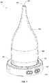
- FIG. 1 illustrates a diffuser 100 for diffusing liquid into surrounding ambient air.
- the diffuser 100 includes a base member 102, a liquid reservoir 104 mounted to the base member 102, and a spout 106 sized and configured to rest upon the liquid reservoir.
- the spout 106 includes an opening 108 at an upper end 110 thereof, through which air and atomized droplets of liquid carried by the air are expelled out from the diffuser into the surrounding ambient air.
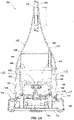
- FIG. 2A is a cross-sectional side view of the diffuser 100.
- the base member 102 has an upper surface 112 and a lower surface 114.
- the liquid reservoir 104 is mounted to the base member 102 over the upper surface 112 thereof.
- at least a portion 118 of the upper surface 112 of the base member 102 may extend laterally beyond an outer peripheral side surface 120 of the liquid reservoir 104. This portion 118 may allow a decorative cover to rest upon the portion 118 of the upper surface 112 of the base member 102, as discussed in further detail subsequently herein.
- the liquid reservoir 104 has surfaces defining a receptacle 116 for holding a volume of liquid therein.
- the liquid reservoir 104 may include a bottom wall 122 and at least one vertically extending sidewall 124. An inner surface of the sidewall 124 and an upper surface of the bottom wall 122 may define the receptacle 116 for holding liquid.
- the bottom wall 122 may not be flat, and may taper to a lowermost point on the upper surface of the bottom wall 122 so as to funnel fluid held within the receptacle 116 toward the lowermost point on the upper surface of the bottom wall 122.
- the liquid reservoir 104 may include an exterior sidewall 138 extending upwardly from the base member 102 and adjoining an upper end of the at least one vertically extending sidewall 124 of the liquid reservoir 104.
- the diffuser 100 further includes an ultrasonic transducer 126 mounted to the base member 102 over the upper surface thereof.
- the ultrasonic transducer 126 is shown in FIGS. 2A and 5 .
- the ultrasonic transducer 126 may be indirectly mounted to the base member 102 by way of the liquid reservoir 104.
- the ultrasonic transducer 126 may be mounted to the liquid reservoir at the lower end thereof.
- the bottom wall 122 of the liquid reservoir 104 may have an aperture 128 formed therethrough at the lowermost point of the bottom wall 122.
- a surface of the ultrasonic transducer 126 may be exposed at the bottom of the aperture 128, such that the surface of the ultrasonic transducer 126 is exposed to any volume of liquid held within the receptacle 116.
- the ultrasonic transducer 126 converts electrical energy into ultrasonic mechanical vibrations.
- the exposed surface of the ultrasonic transducer 126 may vibrate at ultrasonic frequencies during operation of the diffuser 100.
- the ultrasonic vibrations of the ultrasonic transducer 126 generate atomized droplets of the liquid held within the receptacle 116.
- the atomized droplets of the liquid may be generated over the surface of the volume of liquid held within the liquid reservoir 104.
- the diffuser 100 includes a fan 130.
- the fan 130 is mounted to the base member 102, and is configured to force airflow from the exterior of the diffuser 100, into the base member 102, around the receptacle 116 in the liquid reservoir 104, into a volume of space enclosed by the spout 106 and the liquid reservoir 104 overlying any volume of liquid held within the receptacle 116, and out through the opening 108 at the upper end 110 of the spout 106 to the ambient air external to the diffuser 100.
- the forced airflow driven by the fan 130 carries the atomized droplets of the liquid generated by the ultrasonic transducer 126 to the exterior of the diffuser 100 through the opening 108 at the upper end 110 of the spout 106.
- one or more apertures may be formed through the lower wall of the base member 102 vertically below the fan 130, and the air outside the diffuser 100 may be drawn into the base member 102 by the fan 130 through the apertures in the lower wall of the base member 102.
- the exterior sidewall 138 of the liquid reservoir 104 may have at least one aperture 140 extending therethough to allow the forced airflow generated by the fan 130 to pass from a space between the base member 102 and the liquid reservoir 104, around the receptacle 116, and into the volume of space enclosed by the spout 106 and the liquid reservoir 104 overlying any volume of liquid held within the receptacle 116.
- the liquid reservoir 104 is shown separately from the other components of the diffuser 100 in FIGS. 9A and 9B .
- the liquid reservoir 104 may further include a shroud member 142 extending laterally from the exterior sidewall 138 of the liquid reservoir 104 over the aperture 140 extending through the exterior sidewall 138.
- the shroud member 142 may be sized and configured to prevent liquid condensing on interior surfaces of the spout 106 from falling through the aperture 140 and into the space between the base member 102 and the liquid reservoir 104.
- the aperture 140 may be elongated in the horizontal direction, and may be arcuate and curved downward.
- the shroud member 142 may be arcuate, and curved downward in similar fashion.
- the shroud member 142 may be located immediately above the aperture 140 as shown in FIG. 9A .
- the liquid reservoir 104 may also include a liquid spout 143 located and configured for pouring liquid out from the receptacle 116 as needed after use of the diffuser 100.
- the diffuser 100 may include a heat sink 132.
- the heat sink 132 may comprise a metal body shaped and configured to draw heat away from other active, heat-generating components of the diffuser, such as the fan 130, the ultrasonic transducer 126, and a lighting system, which is described in further detail below.
- the heat sink 132 may be mounted to the base member 102 vertically above the fan 130.
- the diffuser 100 may include a lighting system.
- the lighting system may comprise one or more light-emitting diodes (LEDs) 134.
- the LEDs 134 may be used to generate light that may be visible from the exterior of the diffuser 100.
- the one or more LEDs 134 may be disposed between the base member 102 and the liquid reservoir 104.
- a printed circuit board 136 having a plurality of LEDs 134 mounted thereon may be mounted on the base member 102 vertically over the heat sink 132 and fan 130, and underneath the liquid reservoir 104.
- the liquid reservoir 104 and the spout 106 may be at least substantially transparent, or at least substantially translucent to the light emitted by the LEDs 134, such that light emitted by the LEDs can pass through the liquid receptacle 104 and the spout 106.
- the LEDs 134 may be capable of emitting two or more colors of light. For example, a user may be able to select whether the light emitted by the LEDs is white, orange, red, green, blue, or purple. In one operational mode, the LEDs may emit a single selected color. In another operational mode, the LEDs may cycle through the various colors of light emitting each color for a duration of time, such as a few seconds or more, or a few minutes or more.
- the spout 106 may include an outer sidewall 144 configured to rest upon the liquid reservoir 104.
- the lower end of the outer sidewall 144 of the spout 106 may rest upon a shoulder formed toward the upper end of the exterior sidewall 138 of the liquid reservoir 104.
- An annular laterally-projecting ridge may be formed on one or both of the abutting surfaces of the outer sidewall 144 of the spout 106 and the exterior sidewall 138 of the liquid reservoir 104, so as to provide an interference fit therebetween and provide a substantially air-tight seal therebetween so as to prevent airflow generated from the fan from escaping laterally out from the diffuser 100 at the interface between the spout 106 and the liquid reservoir 104.
- the outer sidewall 144 of the spout 106 and the exterior sidewall 138 of the liquid reservoir 104 may be sized and configured such that the exterior surfaces thereof are smooth and continuous across the interface therebetween.
- the spout 106 may further include an interior vertical baffle wall 146 extending between an upper end 148 and a lower end 150 thereof.
- the upper end 148 of the baffle wall 146 may adjoin an interior surface of the outer sidewall 144 of the spout 106.
- the lower end 150 of the baffle wall 146 may be positioned vertically over the receptacle 116 of the liquid reservoir 104 such that liquid condensing on interior surfaces of the spout 106 will drain down an interior side surface of the baffle wall 146 and fall back into the receptacle 116 of the liquid reservoir 104.
- the spout 106 is shown separately from the other components of the diffuser 100 in FIGS. 10A and 10B . As shown therein, the spout 106 may further include a splash guard 152 located within the spout 106 proximate the opening 108 at the upper end 110 thereof. The splash guard 152 may be configured to prevent fluid held within the receptacle 116 of the liquid reservoir 104 from splashing out from the diffuser 100 through the opening 108 at the upper end 110 thereof.
- the ultrasonic vibrations generated within the liquid by the ultrasonic transducer 126 may cause splashing of the liquid, and the splash guard 152 may retain the splashing liquid within the space enclosed by the spout 106 and the liquid reservoir 104 over the bath of liquid held in the receptacle 116.
- the splash guard 152 may include a lower surface 154 oriented at least substantially transverse to a longitudinal axis of the spout 106.
- the lower surface 154 of the splash guard 152 may be located a distance D from the upper end 110 of the spout 106.
- the distance D may be, for example, between about 3.8 cm (1.5 inches) and about 5.1 cm (2.0 inches) from the upper end 110 of the spout 106.
- the lower surface 154 of the splash guard 152 may have a width W SG ( FIG. 2A ) in a plane transverse to the longitudinal axis of the spout 106 that is greater than or equal to a maximum width W OP ( FIG.
- the opening 108 may have a maximum width W OP (e.g., a diameter) of, for example, between about 0.6 cm (0.25 inches) and about 1.9 cm (0.75 inches) (e.g., about 0.795 cm i.e. 0.313 inches).
- W OP e.g., a diameter
- the baffle wall 146 may be generally cylindrical, but may include a portion 147 that curves radially inwardly so as to form a recess in the cylindrical profile of the baffle wall 146.
- This recess may facilitate airflow passing through the diffuser 100 generated by the fan 130.
- the recess may facilitate the passage of the airflow between the liquid reservoir 104 and the spout 106 so as to allow the flowing air to enter the space enclosed by the liquid reservoir 104 and the spout 106 in the region overlying the liquid held within the receptacle 116.
- the portion 118 of the upper surface 112 of the base member 102 that extends laterally beyond the outer peripheral side surface 120 of the liquid reservoir 104 may be disposed at a lower elevation relative to portions 119 of the upper surface 112 of the base member 102 that are disposed within the liquid reservoir 104.
- This configuration reduces the risk of liquid that might unintentionally drip or fall down the exterior surface of the spout 106 and the liquid reservoir 104 from entering into the interior of the base member 102 and contacting the various active and electronic components of the diffuser 100.
- the lower end of the exterior sidewall 138 of the liquid reservoir 104 may disposed in an annular recess formed in the upper surface 112 of the base member 102, and an elastomeric seal ring may be disposed in the recess and between the upper surface 112 of the base member 102 and the exterior sidewall 138 of the liquid reservoir 104 to establish an at least substantially air- and liquid-tight seal therebetween, which may further reduce the risk of liquid from entering into the interior of the liquid receptacle 104 from the exterior thereof and contacting the various active and electronic components of the diffuser 100.
- FIG. 7 is a front side view of the diffuser 100 and illustrates a polymeric gasket 160 of the diffuser 100 positioned thereon.
- the polymeric gasket 160 is not illustrated in FIGS. 1 , 2A , and 2B .
- the polymeric gasket 160 is also shown in FIGS. 8A and 8B separate from the other components of the diffuser 100.
- the polymeric gasket may comprise an elastomeric gasket that is at least substantially formed of and comprises an elastomeric polymer, such as silicone, although the gasket 160 may be formed from and comprise other elastomeric materials in additional embodiments.
- the polymeric gasket 160 encircles the liquid reservoir 104 about the lower region of the exterior sidewall 138 of the liquid reservoir 104.
- the polymeric gasket 160 includes a cylindrical wall 161, a first lower flange 162, and a second upper flange 164.
- the polymeric gasket 160 may include only one flange, or the polymeric gasket 160 may include more than two flanges.
- the lower flange 162 may extend laterally from the bottom of the cylindrical wall 161, and a lower surface 166 of the lower flange 162 may define a bottom surface of the gasket 160.
- the lower surface 166 may be at least substantially planar, and may be configured to rest upon the portion 118 of the upper surface 112 of the base member 102 that extends laterally beyond the outer peripheral side surface 120 of the liquid reservoir 104 when the gasket 160 is positioned around the liquid reservoir 104 and on the base member 102, as shown in FIG. 7 .
- the lower flange 160 extends at least partially over the portion 118 of the upper surface 112 of the base member 102 that extends laterally beyond the outer peripheral side surface 120 of the liquid reservoir 104.
- an upper surface of the lower gasket 162 may taper downward toward the lower surface 166 of the lower gasket in the direction extending laterally outward away from the cylindrical wall 161 of the gasket 160.
- the upper flange 164 may extend radially outward from the cylindrical wall 161 from an intermediate location between the upper and lower ends of the cylindrical wall 161.
- the upper flange 164 may extend radially outward from the cylindrical wall 161 at a location in the upper half of the cylindrical wall 161 between the horizontal centerline and the upper end of the cylindrical wall 161, as shown in FIG. 8B .
- the upper flange 164 may be tapered in the radial direction.
- one or both of the upper and lower surfaces of the upper flange 164 may be tapered, and may taper toward one another in the direction extending laterally outward away from the cylindrical wall 161 of the gasket 160, as shown in FIG. 8B .
- annular recess 168 may be formed in the outer peripheral side surface 120 of the liquid reservoir 104.
- the annular recess 168 may have a height and depth that are substantially the same as, or slightly greater than, the height and width, respectively, of the cylindrical wall 161.
- the cylindrical wall 161 of the gasket 160 may rest at least substantially entirely within the annular recess 168 in the outer peripheral side surface 120 of the liquid reservoir 104 when the gasket 160 is positioned around the liquid reservoir 104 and on the base member 102.
- the polymeric gasket 160 may be at least partially transparent (e.g., translucent) to the light emitted by the one or more LEDs 134 so that the light emitted by the LEDs 134 is visible through the gasket 160.
- the diffuser 100 may further include a removable decorative cover 170 that is sized and configured to be positioned over and around the liquid reservoir 104 and the spout 106 ( FIG. 1 ), and to rest upon the lower flange 162 of the polymeric gasket 160 over the base member 102 ( FIG. 7 ).
- the lower flange 162 of the gasket 160 is disposed between the cover 170 and the portion 118 of the upper surface 112 of the base member 102 that extends laterally beyond the outer peripheral side surface 120 of the liquid reservoir 104.
- the cover 170 includes an opening at an upper end 172 thereof such that the forced airflow generated by the fan 130 passes through the opening at the upper end 172 of the cover 170.
- the light emitted by the LEDs 134 may be visible through the opening at the upper end 172 of the cover 170.
- the gasket 160 may also be transparent or translucent to the light emitted by the LEDs 134, and the light emitted by the LEDs may be visible through the lower flange 162 of the gasket 160 at the interface between the cover 170 and the upper surface 112 of the base member 102 so as to provide a visible ring of light around the base of the cover 170 during operation of the diffuser 100.
- the diffuser 100 is configured so as to operate with or without a decorative cover 170 thereon, and the airflow through the diffuser is not affected by the presence or absence of a decorative cover 170 resting on the base member 102.
- the interior surfaces of the decorative cover 170 do not define any passageway for the forced airflow through the diffuser 100 generated by the fan 130.
- the diffuser 100 may be part of a kit that includes the base member 102, the liquid reservoir 104, and the spout 106 (with the various other components mounted therein and described with reference to FIGS. 2A , 2B , 3 through 7 , 8A, and 8B ), as well as two or more decorative covers 170 having different aesthetic appearances.
- the two or more decorative covers may be interchangeable on the diffuser 100 so as to allow a user to alter a decorative appearance of the diffuser 100.
- the diffuser 100 may be part of a kit that includes the base member 102, the liquid reservoir 104, and the spout 106 (with the various other components mounted therein and described with reference to FIGS. 2A , 2B , 3 through 7 , 8A, and 8B ), as well as two or more decorative covers 170 having different aesthetic appearances.
- the two or more decorative covers may be interchangeable on the diffuser 100 so as to allow a user to alter a decorative appearance of the diffuser 100.
Landscapes
- Health & Medical Sciences (AREA)
- Epidemiology (AREA)
- Life Sciences & Earth Sciences (AREA)
- Animal Behavior & Ethology (AREA)
- General Health & Medical Sciences (AREA)
- Public Health (AREA)
- Veterinary Medicine (AREA)
- Engineering & Computer Science (AREA)
- General Engineering & Computer Science (AREA)
- Special Spraying Apparatus (AREA)
Description
- Embodiments of the present disclosure relate generally to diffusers for diffusing liquids into the ambient air, and to methods of assembling and using such diffusers.
- Diffusers are devices that are used to generate atomized droplets of liquids and to disperse the atomized droplets of liquid into the ambient air surrounding the diffuser. For example, some diffusers are used for humidification. Diffusers are also used for aroma therapy, wherein scented oils or other therapeutic liquids are atomized and dispensed into the surrounding ambient air. Diffusers often employ an ultrasonic transducer to generate ultrasonic vibrations in a bath of liquid held within the diffuser. A fan is used to generate airflow through the diffuser, the airflow carrying the atomized droplets of liquid generated by the ultrasonic transducer out from the diffuser and into the surrounding ambient air.
US 2011/024521A1 ,GB2473290A US2011/049266A1 each disclose known diffusers. - The invention is defined by claim 1.
- In some embodiments and comparative examples, the present disclosure includes a diffuser for diffusing liquid into surrounding ambient air. The diffuser includes a base member, an ultrasonic transducer, a liquid reservoir, a spout, a fan, a polymeric gasket, and a cover. The base member has an upper surface and a lower surface. The ultrasonic transducer is mounted to the base member over the upper surface thereof. The liquid reservoir is mounted to the base member over the upper surface thereof. The liquid reservoir has surfaces defining a receptacle for holding a volume of liquid therein. At least a portion of an upper surface of the base member extends laterally beyond an outer peripheral side surface of the liquid reservoir. The liquid reservoir includes a bottom wall and at least one vertically extending sidewall. At least a surface of the ultrasonic transducer is exposed to any volume of liquid held within the receptacle such that ultrasonic vibrations of the ultrasonic transducer generate atomized droplets of the liquid over the volume of liquid held within the reservoir.
- The spout is sized and configured to rest upon the liquid reservoir and includes an opening at an upper end thereof. The fan is mounted to the base member and configured to force airflow from the exterior of the diffuser, into the base member, around the receptacle in the liquid reservoir, into a volume of space enclosed by the spout and the liquid reservoir overlying any volume of liquid held within the receptacle, and out through the opening at the upper end of the spout to the ambient air external the diffuser. The forced airflow carries the atomized droplets of the liquid generated by the ultrasonic transducer to the exterior of the diffuser through the opening at the upper end of the spout.
- The polymeric gasket encircles the liquid reservoir and includes at least one flange that extends at least partially over the portion of the upper surface of the base member extending laterally beyond the outer peripheral side surface of the liquid reservoir.
- The cover is sized and configured to be positioned over and around the liquid reservoir and the spout, and to rest upon the at least one flange of the polymeric gasket such that the at least one flange is disposed between the cover and the portion of the upper surface of the base member extending laterally beyond the outer peripheral side surface of the liquid reservoir. The cover includes at least one opening at an upper end thereof such that the forced airflow generated by the fan passes through the opening at the upper end of the cover.
- In comparative examples, the present disclosure includes methods of assembling such a liquid diffuser. For example, a structure may be provided that includes a base member, an ultrasonic transducer, a liquid reservoir, a fan, and a polymeric gasket. The base member has an upper surface and a lower surface, and the ultrasonic transducer is mounted to the base member over the upper surface thereof. The liquid reservoir is mounted to the base member over the upper surface thereof. The liquid reservoir has surfaces defining a receptacle for holding a volume of liquid therein. At least a portion of an upper surface of the base member extends laterally beyond an outer peripheral side surface of the liquid reservoir. The liquid reservoir includes a bottom wall and at least one vertically extending sidewall. At least a surface of the ultrasonic transducer is exposed to any volume of liquid held within the receptacle such that ultrasonic vibrations of the ultrasonic transducer generate atomized droplets of the liquid over the volume of liquid held within the reservoir. The fan is mounted to the base member and configured to force airflow from the exterior of the diffuser, into the base member, and around the receptacle in the liquid reservoir. The forced airflow carries the atomized droplets of the liquid generated by the ultrasonic transducer to the exterior of the diffuser. The polymeric gasket encircles the liquid reservoir and includes at least one flange that extends at least partially over the portion of the upper surface of the base member extending laterally beyond the outer peripheral side surface of the liquid reservoir.
- After providing such a structure, a spout is rested upon the liquid reservoir. The spout includes an opening at an upper end thereof and encloses a volume of space between the spout and the liquid reservoir.
- A cover is then positioned over and around the liquid reservoir, and the spout is rested upon the at least one flange of the polymeric gasket such that the at least one flange is disposed between the cover and the portion of the upper surface of the base member extending laterally beyond the outer peripheral side surface of the liquid reservoir. The cover includes at least one opening at an upper end thereof such that the forced airflow generated by the fan passes through the opening at the upper end of the cover.
- In yet further comparative examples, the present disclosure includes methods of using a liquid diffuser. For example, a liquid diffuser is provided that includes a base member, an ultrasonic transducer, a liquid reservoir, a spout, a fan, a polymeric gasket, and a cover. The base member has an upper surface and a lower surface. The ultrasonic transducer is mounted to the base member over the upper surface thereof. The liquid reservoir is mounted to the base member over the upper surface thereof. The liquid reservoir has surfaces defining a receptacle for holding a volume of liquid therein. At least a portion of an upper surface of the base member extends laterally beyond an outer peripheral side surface of the liquid reservoir. The liquid reservoir includes a bottom wall and at least one vertically extending sidewall. At least a surface of the ultrasonic transducer is exposed to any volume of liquid held within the receptacle. The spout is sized and configured to rest upon the liquid reservoir and includes an opening at an upper end thereof. The fan is mounted to the base member. The polymeric gasket encircles the liquid reservoir and includes at least one flange that extends at least partially over the portion of the upper surface of the base member extending laterally beyond the outer peripheral side surface of the liquid reservoir. The cover includes at least one opening at an upper end thereof.
- After providing the liquid diffuser, a volume of liquid is provided in the receptacle of the liquid reservoir. The spout is then rested upon the liquid reservoir, and the cover is positioned over and around the liquid reservoir and the spout and rested upon the at least one flange of the polymeric gasket such that the at least one flange is disposed between the cover and the portion of the upper surface of the base member extending laterally beyond the outer peripheral side surface of the liquid reservoir.
- Power is then supplied to the ultrasonic transducer and atomized droplets of the liquid are generated over the volume of liquid held within the reservoir by ultrasonic vibrations of the ultrasonic transducer. Power is also supplied to the fan such that the fan forces airflow from the exterior of the diffuser, into the base member, around the receptacle in the liquid reservoir, into a volume of space enclosed by the spout and the liquid reservoir overlying the volume of liquid held within the receptacle, and out through the opening at the upper end of the spout to the ambient air external the diffuser. The forced airflow carries the atomized droplets of the liquid generated by the ultrasonic transducer to the exterior of the diffuser through the opening at the upper end of the spout.
- In a first broad independent aspect, the invention provides a diffuser according to claim 1.
- Dependent aspects are provided in the dependent claims.
- Preferably, the polymeric gasket comprises an elastomeric gasket.
- Preferably, at least one light-emitting diode (LED) disposed between the base member and the liquid reservoir, wherein light emitted by the at least one LED is visible from the exterior of the diffuser.
- Preferably, the light emitted by the at least one LED is visible through the opening at the upper end of the cover.
- Preferably, the polymeric gasket is at least partially transparent to the light emitted by the at least one LED, the light emitted by the at least one LED being visible through the at least one flange of the polymeric gasket at an interface between the cover and the upper surface of the base member.
- Preferably, the at least one LED comprises a plurality of LEDs capable of emitting two or more colors of light.
- Preferably, the spout includes an outer sidewall configured to rest upon the liquid reservoir, and an interior vertical baffle wall extending between an upper end and a lower end, the upper end of the baffle wall adjoining an interior surface of the outer sidewall of the spout, the lower end of the baffle wall positioned vertically over the receptacle of the liquid reservoir such that liquid condensing on interior surfaces of the spout will drain down an interior side surface of the baffle wall and fall back into the liquid reservoir.
- Preferably, the liquid reservoir includes an exterior sidewall extending upwardly from the base member and adjoining an upper end of the at least one vertically extending sidewall of the liquid reservoir, the exterior sidewall having at least one aperture extending therethrough to allow the forced airflow generated by fan to pass from a space between the base member and the liquid reservoir, around the receptacle, and into the volume of space enclosed by the spout and the liquid reservoir overlying any volume of liquid held within the receptacle.
- Preferably, the liquid reservoir further includes a shroud member extending from the exterior sidewall over the at least one aperture extending therethrough, the shroud member sized and configured to prevent liquid condensing on interior surfaces of the spout from falling through the at least one aperture and into the space between the base member and the liquid reservoir.
- Preferably, the spout further includes a splash guard located within the spout proximate the opening at the upper end thereof, the splash guard configured to prevent fluid held within the receptacle of the liquid reservoir from splashing out from the diffuser through the opening at the upper end thereof.
- Preferably, the splash guard includes a lower surface oriented at least substantially transverse to a longitudinal axis of the spout.
- Preferably, the lower surface of the splash guard is located between about 0.6cm (0.25 inches) and about 1.9 cm (0.75 inches) from the upper end of the spout.
- Preferably, the lower surface of the splash guard has a width in a plane transverse to the longitudinal axis of the spout that is greater than or equal to a maximum width of the opening at the upper end of the spout in a plane transverse to the longitudinal axis of the spout.
- In a comparative example, there is provided a method of assembling a diffuser for diffusing liquid into surrounding ambient air, comprising: providing a structure including: a base member having an upper surface and a lower surface; an ultrasonic transducer mounted to the base member over the upper surface thereof; a liquid reservoir mounted to the base member over the upper surface thereof, the liquid reservoir having surfaces defining a receptacle for holding a volume of liquid therein, at least a portion of an upper surface of the base member extending laterally beyond an outer peripheral side surface of the liquid reservoir, the liquid reservoir including a bottom wall and at least one vertically extending sidewall, at least a surface of the ultrasonic transducer exposed to any volume of liquid held within the receptacle such that ultrasonic vibrations of the ultrasonic transducer generate atomized droplets of the liquid over the volume of liquid held within the reservoir; a fan mounted to the base member and configured to force airflow from the exterior of the diffuser, into the base member, and around the receptacle in the liquid reservoir, the forced airflow carrying the atomized droplets of the liquid generated by the ultrasonic transducer to the exterior of the diffuser; and a polymeric gasket encircling the liquid reservoir and including at least one flange, the at least one flange extending at least partially over the portion of the upper surface of the base member extending laterally beyond the outer peripheral side surface of the liquid reservoir; resting a spout upon the liquid reservoir, the spout including an opening at an upper end thereof and enclosing a volume of space between the spout and the liquid reservoir; and positing a cover over and around the liquid reservoir and the spout and resting the spout upon the at least one flange of the polymeric gasket such that the at least one flange is disposed between the cover and the portion of the upper surface of the base member extending laterally beyond the outer peripheral side surface of the liquid reservoir, the cover including at least one opening at an upper end thereof such that the forced airflow generated by the fan passes through the opening at the upper end of the cover.
- Preferably, the structure further comprises at least one light-emitting diode (LED) disposed between the base member and the liquid reservoir, and wherein the polymeric gasket is at least partially transparent to the emitted by the at least one LED, the light emitted by the at least one LED being visible through the at least one flange of the polymeric gasket at an interface between the cover and the upper surface of the base member.
-
-
FIG. 1 is a perspective view of a diffuser for diffusing liquid into surrounding ambient air according to an embodiment of the present disclosure. -
FIG. 2A is a cross-sectional side view of the diffuser ofFIG. 1 . -
FIG. 2B is identical toFIG. 2A , but does not include reference characters, and illustrates cut-away planes of the views ofFIGS. 3 through 6 . -
FIG. 3 is a perspective view of the diffuser ofFIG. 1 , cut-away along plane 3-3 inFIG. 1 . -
FIG. 4 is a perspective view of the diffuser ofFIG. 1 , cut-away along plane 4-4 inFIG. 1 . -
FIG. 5 is a perspective view of the diffuser ofFIG. 1 , cut-away along plane 5-5 inFIG. 1 . -
FIG. 6 is a perspective view of the diffuser ofFIG. 1 , cut-away along plane 6-6 inFIG. 1 . -
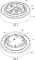
FIG. 7 is a front side view of the diffuser illustrating a polymeric gasket of the diffuser positioned around a liquid reservoir of the diffuser. -
FIG. 8A is a perspective view of the polymeric gasket shown inFIG. 7 . -
FIG. 8B is a side view of the polymeric gasket ofFIG. 8A . -
FIGS. 9A and 9B are perspective views of a liquid reservoir of the diffuser ofFIG. 1 . -
FIG. 10A is a cross-sectional side view of a spout of the diffuser ofFIG. 1 separate from the other components of the diffuser. -
FIG. 10B is bottom view of the spout ofFIG. 10 . -
FIG. 11 illustrates a decorative cover positioned over and around the diffuser ofFIG. 1 . - The illustrations presented herein are not meant to be actual views of any particular diffuser, component thereof, or method, but are merely idealized representations which are employed to describe certain embodiments of the present disclosure. For clarity in description, various features and elements common among the illustrated embodiments may be referenced with the same or similar reference numerals.
- As used herein, any directional term (e.g., upper, lower, side, top, bottom, etc.) refers to a direction relative to the diffuser when the diffuser is used during normal operation. By way of non-limiting example, an upper portion of a diffuser is the upper portion while the diffuser is placed on a surface in an orientation for use, and used to diffuse liquid into the ambient air.
-
FIG. 1 illustrates adiffuser 100 for diffusing liquid into surrounding ambient air. Thediffuser 100 includes abase member 102, aliquid reservoir 104 mounted to thebase member 102, and aspout 106 sized and configured to rest upon the liquid reservoir. Thespout 106 includes anopening 108 at anupper end 110 thereof, through which air and atomized droplets of liquid carried by the air are expelled out from the diffuser into the surrounding ambient air. -
FIG. 2A is a cross-sectional side view of thediffuser 100. As shown therein, thebase member 102 has anupper surface 112 and alower surface 114. Theliquid reservoir 104 is mounted to thebase member 102 over theupper surface 112 thereof. As shown inFIG. 2A , at least aportion 118 of theupper surface 112 of thebase member 102 may extend laterally beyond an outerperipheral side surface 120 of theliquid reservoir 104. Thisportion 118 may allow a decorative cover to rest upon theportion 118 of theupper surface 112 of thebase member 102, as discussed in further detail subsequently herein. - As shown in
FIG. 2A , theliquid reservoir 104 has surfaces defining areceptacle 116 for holding a volume of liquid therein. For example, theliquid reservoir 104 may include abottom wall 122 and at least one vertically extendingsidewall 124. An inner surface of thesidewall 124 and an upper surface of thebottom wall 122 may define thereceptacle 116 for holding liquid. Thebottom wall 122 may not be flat, and may taper to a lowermost point on the upper surface of thebottom wall 122 so as to funnel fluid held within thereceptacle 116 toward the lowermost point on the upper surface of thebottom wall 122. Theliquid reservoir 104 may include anexterior sidewall 138 extending upwardly from thebase member 102 and adjoining an upper end of the at least one vertically extendingsidewall 124 of theliquid reservoir 104. - The
diffuser 100 further includes anultrasonic transducer 126 mounted to thebase member 102 over the upper surface thereof. Theultrasonic transducer 126 is shown inFIGS. 2A and5 . As shown inFIG. 2A , theultrasonic transducer 126 may be indirectly mounted to thebase member 102 by way of theliquid reservoir 104. For example, theultrasonic transducer 126 may be mounted to the liquid reservoir at the lower end thereof. Thebottom wall 122 of theliquid reservoir 104 may have anaperture 128 formed therethrough at the lowermost point of thebottom wall 122. A surface of theultrasonic transducer 126 may be exposed at the bottom of theaperture 128, such that the surface of theultrasonic transducer 126 is exposed to any volume of liquid held within thereceptacle 116. Theultrasonic transducer 126 converts electrical energy into ultrasonic mechanical vibrations. In particular, the exposed surface of theultrasonic transducer 126 may vibrate at ultrasonic frequencies during operation of thediffuser 100. The ultrasonic vibrations of theultrasonic transducer 126 generate atomized droplets of the liquid held within thereceptacle 116. The atomized droplets of the liquid may be generated over the surface of the volume of liquid held within theliquid reservoir 104. - As shown in
FIGS. 2A and3 , thediffuser 100 includes afan 130. Thefan 130 is mounted to thebase member 102, and is configured to force airflow from the exterior of thediffuser 100, into thebase member 102, around thereceptacle 116 in theliquid reservoir 104, into a volume of space enclosed by thespout 106 and theliquid reservoir 104 overlying any volume of liquid held within thereceptacle 116, and out through theopening 108 at theupper end 110 of thespout 106 to the ambient air external to thediffuser 100. The forced airflow driven by thefan 130 carries the atomized droplets of the liquid generated by theultrasonic transducer 126 to the exterior of thediffuser 100 through theopening 108 at theupper end 110 of thespout 106. For example, one or more apertures may be formed through the lower wall of thebase member 102 vertically below thefan 130, and the air outside thediffuser 100 may be drawn into thebase member 102 by thefan 130 through the apertures in the lower wall of thebase member 102. Theexterior sidewall 138 of theliquid reservoir 104 may have at least oneaperture 140 extending therethough to allow the forced airflow generated by thefan 130 to pass from a space between thebase member 102 and theliquid reservoir 104, around thereceptacle 116, and into the volume of space enclosed by thespout 106 and theliquid reservoir 104 overlying any volume of liquid held within thereceptacle 116. - The
liquid reservoir 104 is shown separately from the other components of thediffuser 100 inFIGS. 9A and 9B . As shown therein, theliquid reservoir 104 may further include ashroud member 142 extending laterally from theexterior sidewall 138 of theliquid reservoir 104 over theaperture 140 extending through theexterior sidewall 138. Theshroud member 142 may be sized and configured to prevent liquid condensing on interior surfaces of thespout 106 from falling through theaperture 140 and into the space between thebase member 102 and theliquid reservoir 104. In some embodiments, theaperture 140 may be elongated in the horizontal direction, and may be arcuate and curved downward. Theshroud member 142 may be arcuate, and curved downward in similar fashion. Theshroud member 142 may be located immediately above theaperture 140 as shown inFIG. 9A . - The
liquid reservoir 104 may also include aliquid spout 143 located and configured for pouring liquid out from thereceptacle 116 as needed after use of thediffuser 100. - As also shown in
FIGS. 2A and3 , thediffuser 100 may include aheat sink 132. Theheat sink 132 may comprise a metal body shaped and configured to draw heat away from other active, heat-generating components of the diffuser, such as thefan 130, theultrasonic transducer 126, and a lighting system, which is described in further detail below. Theheat sink 132 may be mounted to thebase member 102 vertically above thefan 130. - The
diffuser 100 may include a lighting system. The lighting system may comprise one or more light-emitting diodes (LEDs) 134. TheLEDs 134 may be used to generate light that may be visible from the exterior of thediffuser 100. In some embodiments, the one ormore LEDs 134 may be disposed between thebase member 102 and theliquid reservoir 104. For example, as shown inFIGS. 2A and4 , a printedcircuit board 136 having a plurality ofLEDs 134 mounted thereon may be mounted on thebase member 102 vertically over theheat sink 132 andfan 130, and underneath theliquid reservoir 104. In some embodiments, theliquid reservoir 104 and thespout 106 may be at least substantially transparent, or at least substantially translucent to the light emitted by theLEDs 134, such that light emitted by the LEDs can pass through theliquid receptacle 104 and thespout 106. - In some embodiments, the
LEDs 134 may be capable of emitting two or more colors of light. For example, a user may be able to select whether the light emitted by the LEDs is white, orange, red, green, blue, or purple. In one operational mode, the LEDs may emit a single selected color. In another operational mode, the LEDs may cycle through the various colors of light emitting each color for a duration of time, such as a few seconds or more, or a few minutes or more. - Referring again to
FIG. 2A , thespout 106 may include anouter sidewall 144 configured to rest upon theliquid reservoir 104. In particular, the lower end of theouter sidewall 144 of thespout 106 may rest upon a shoulder formed toward the upper end of theexterior sidewall 138 of theliquid reservoir 104. An annular laterally-projecting ridge may be formed on one or both of the abutting surfaces of theouter sidewall 144 of thespout 106 and theexterior sidewall 138 of theliquid reservoir 104, so as to provide an interference fit therebetween and provide a substantially air-tight seal therebetween so as to prevent airflow generated from the fan from escaping laterally out from thediffuser 100 at the interface between thespout 106 and theliquid reservoir 104. Theouter sidewall 144 of thespout 106 and theexterior sidewall 138 of theliquid reservoir 104 may be sized and configured such that the exterior surfaces thereof are smooth and continuous across the interface therebetween. Thespout 106 may further include an interiorvertical baffle wall 146 extending between anupper end 148 and alower end 150 thereof. Theupper end 148 of thebaffle wall 146 may adjoin an interior surface of theouter sidewall 144 of thespout 106. When thespout 106 is positioned on theliquid reservoir 104 as shown inFIG. 2A , thelower end 150 of thebaffle wall 146 may be positioned vertically over thereceptacle 116 of theliquid reservoir 104 such that liquid condensing on interior surfaces of thespout 106 will drain down an interior side surface of thebaffle wall 146 and fall back into thereceptacle 116 of theliquid reservoir 104. - The
spout 106 is shown separately from the other components of thediffuser 100 inFIGS. 10A and 10B . As shown therein, thespout 106 may further include asplash guard 152 located within thespout 106 proximate theopening 108 at theupper end 110 thereof. Thesplash guard 152 may be configured to prevent fluid held within thereceptacle 116 of theliquid reservoir 104 from splashing out from thediffuser 100 through theopening 108 at theupper end 110 thereof. In particular, during operation of thediffuser 100, the ultrasonic vibrations generated within the liquid by theultrasonic transducer 126 may cause splashing of the liquid, and thesplash guard 152 may retain the splashing liquid within the space enclosed by thespout 106 and theliquid reservoir 104 over the bath of liquid held in thereceptacle 116. - The
splash guard 152 may include alower surface 154 oriented at least substantially transverse to a longitudinal axis of thespout 106. In some embodiments, thelower surface 154 of thesplash guard 152 may be located a distance D from theupper end 110 of thespout 106. For example, the distance D may be, for example, between about 3.8 cm (1.5 inches) and about 5.1 cm (2.0 inches) from theupper end 110 of thespout 106. Thelower surface 154 of thesplash guard 152 may have a width WSG (FIG. 2A ) in a plane transverse to the longitudinal axis of thespout 106 that is greater than or equal to a maximum width WOP (FIG. 2A ) of theopening 108 at theupper end 110 of thespout 106 in a plane transverse to the longitudinal axis of thespout 106. Theopening 108 may have a maximum width WOP (e.g., a diameter) of, for example, between about 0.6 cm (0.25 inches) and about 1.9 cm (0.75 inches) (e.g., about 0.795 cm i.e. 0.313 inches). - As shown in
FIGS. 10A and 10B , thebaffle wall 146 may be generally cylindrical, but may include aportion 147 that curves radially inwardly so as to form a recess in the cylindrical profile of thebaffle wall 146. This recess may facilitate airflow passing through thediffuser 100 generated by thefan 130. In particular, the recess may facilitate the passage of the airflow between theliquid reservoir 104 and thespout 106 so as to allow the flowing air to enter the space enclosed by theliquid reservoir 104 and thespout 106 in the region overlying the liquid held within thereceptacle 116. - Referring again to
FIG. 2A , theportion 118 of theupper surface 112 of thebase member 102 that extends laterally beyond the outerperipheral side surface 120 of theliquid reservoir 104 may be disposed at a lower elevation relative to portions 119 of theupper surface 112 of thebase member 102 that are disposed within theliquid reservoir 104. This configuration reduces the risk of liquid that might unintentionally drip or fall down the exterior surface of thespout 106 and theliquid reservoir 104 from entering into the interior of thebase member 102 and contacting the various active and electronic components of thediffuser 100. Furthermore, the lower end of theexterior sidewall 138 of theliquid reservoir 104 may disposed in an annular recess formed in theupper surface 112 of thebase member 102, and an elastomeric seal ring may be disposed in the recess and between theupper surface 112 of thebase member 102 and theexterior sidewall 138 of theliquid reservoir 104 to establish an at least substantially air- and liquid-tight seal therebetween, which may further reduce the risk of liquid from entering into the interior of theliquid receptacle 104 from the exterior thereof and contacting the various active and electronic components of thediffuser 100. -
FIG. 7 is a front side view of thediffuser 100 and illustrates apolymeric gasket 160 of thediffuser 100 positioned thereon. Thepolymeric gasket 160 is not illustrated inFIGS. 1 ,2A , and2B . Thepolymeric gasket 160 is also shown inFIGS. 8A and 8B separate from the other components of thediffuser 100. The polymeric gasket may comprise an elastomeric gasket that is at least substantially formed of and comprises an elastomeric polymer, such as silicone, although thegasket 160 may be formed from and comprise other elastomeric materials in additional embodiments. As shown inFIG. 7 , thepolymeric gasket 160 encircles theliquid reservoir 104 about the lower region of theexterior sidewall 138 of theliquid reservoir 104. As shown inFIGS. 8A and 8B , thepolymeric gasket 160 includes acylindrical wall 161, a firstlower flange 162, and a secondupper flange 164. In additional embodiments, thepolymeric gasket 160 may include only one flange, or thepolymeric gasket 160 may include more than two flanges. - Referring to
FIG. 8B , thelower flange 162 may extend laterally from the bottom of thecylindrical wall 161, and alower surface 166 of thelower flange 162 may define a bottom surface of thegasket 160. Thelower surface 166 may be at least substantially planar, and may be configured to rest upon theportion 118 of theupper surface 112 of thebase member 102 that extends laterally beyond the outerperipheral side surface 120 of theliquid reservoir 104 when thegasket 160 is positioned around theliquid reservoir 104 and on thebase member 102, as shown inFIG. 7 . Thus, when thegasket 160 positioned around theliquid reservoir 104 and on thebase member 102, thelower flange 160 extends at least partially over theportion 118 of theupper surface 112 of thebase member 102 that extends laterally beyond the outerperipheral side surface 120 of theliquid reservoir 104. Referring again toFIG. 8B , in some embodiments, an upper surface of thelower gasket 162 may taper downward toward thelower surface 166 of the lower gasket in the direction extending laterally outward away from thecylindrical wall 161 of thegasket 160. Theupper flange 164 may extend radially outward from thecylindrical wall 161 from an intermediate location between the upper and lower ends of thecylindrical wall 161. In some embodiments, theupper flange 164 may extend radially outward from thecylindrical wall 161 at a location in the upper half of thecylindrical wall 161 between the horizontal centerline and the upper end of thecylindrical wall 161, as shown inFIG. 8B . In some embodiments, theupper flange 164 may be tapered in the radial direction. For example, one or both of the upper and lower surfaces of theupper flange 164 may be tapered, and may taper toward one another in the direction extending laterally outward away from thecylindrical wall 161 of thegasket 160, as shown inFIG. 8B . - As shown in
FIG. 2A , anannular recess 168 may be formed in the outerperipheral side surface 120 of theliquid reservoir 104. Theannular recess 168 may have a height and depth that are substantially the same as, or slightly greater than, the height and width, respectively, of thecylindrical wall 161. Thus, thecylindrical wall 161 of thegasket 160 may rest at least substantially entirely within theannular recess 168 in the outerperipheral side surface 120 of theliquid reservoir 104 when thegasket 160 is positioned around theliquid reservoir 104 and on thebase member 102. - In some embodiments, the
polymeric gasket 160 may be at least partially transparent (e.g., translucent) to the light emitted by the one ormore LEDs 134 so that the light emitted by theLEDs 134 is visible through thegasket 160. - Referring to
FIG. 11 , thediffuser 100 may further include a removabledecorative cover 170 that is sized and configured to be positioned over and around theliquid reservoir 104 and the spout 106 (FIG. 1 ), and to rest upon thelower flange 162 of thepolymeric gasket 160 over the base member 102 (FIG. 7 ). Thelower flange 162 of thegasket 160 is disposed between thecover 170 and theportion 118 of theupper surface 112 of thebase member 102 that extends laterally beyond the outerperipheral side surface 120 of theliquid reservoir 104. Thecover 170 includes an opening at anupper end 172 thereof such that the forced airflow generated by thefan 130 passes through the opening at theupper end 172 of thecover 170. - During operation of the
diffuser 100, the light emitted by the LEDs 134 (FIG. 2A ) may be visible through the opening at theupper end 172 of thecover 170. In addition, as previously mentioned, thegasket 160 may also be transparent or translucent to the light emitted by theLEDs 134, and the light emitted by the LEDs may be visible through thelower flange 162 of thegasket 160 at the interface between thecover 170 and theupper surface 112 of thebase member 102 so as to provide a visible ring of light around the base of thecover 170 during operation of thediffuser 100. - The
diffuser 100 is configured so as to operate with or without adecorative cover 170 thereon, and the airflow through the diffuser is not affected by the presence or absence of adecorative cover 170 resting on thebase member 102. In other words, the interior surfaces of thedecorative cover 170 do not define any passageway for the forced airflow through thediffuser 100 generated by thefan 130. - In some embodiments, the
diffuser 100 may be part of a kit that includes thebase member 102, theliquid reservoir 104, and the spout 106 (with the various other components mounted therein and described with reference toFIGS. 2A ,2B ,3 through 7 ,8A, and 8B ), as well as two or moredecorative covers 170 having different aesthetic appearances. The two or more decorative covers may be interchangeable on thediffuser 100 so as to allow a user to alter a decorative appearance of thediffuser 100. - In some embodiments, the
diffuser 100 may be part of a kit that includes thebase member 102, theliquid reservoir 104, and the spout 106 (with the various other components mounted therein and described with reference toFIGS. 2A ,2B ,3 through 7 ,8A, and 8B ), as well as two or moredecorative covers 170 having different aesthetic appearances. The two or more decorative covers may be interchangeable on thediffuser 100 so as to allow a user to alter a decorative appearance of thediffuser 100.
Claims (15)
- A diffuser (100) for diffusing liquid into surrounding ambient air, comprising:a base member (102) having an upper surface (112) and a lower surface (114);a liquid reservoir (104) mounted to the base member (102) over the upper surface (112) thereof, the liquid reservoir (104) having surfaces defining a receptacle (116) for holding a volume of liquid therein;an ultrasonic transducer (126) mounted to the base member (102) over the upper surface (112) thereof, at least a surface of the ultrasonic transducer (126) exposed to any volume of liquid held within the receptacle (116) such that ultrasonic vibrations of the ultrasonic transducer (126) generate atomized droplets of the liquid over the volume of liquid held within the reservoir (116);a spout (106) including an opening (108) at an upper end (110) thereof and being sized and configured to rest upon the liquid reservoir (104) at a lower end of the spout (106);a fan (130) mounted to the base member (102) and configured to force airflow from an exterior of the diffuser (100), into the base member (102), around the receptacle (116) of the liquid reservoir (104), into a volume of space enclosed by the spout (106) and the liquid reservoir (104) overlying any volume of liquid held within the receptacle (116), and out through the opening (108) at the upper end (110) of the spout (106) to ambient air external to the diffuser (100), the forced airflow carrying the atomized droplets of the liquid generated by the ultrasonic transducer (126) to the exterior of the diffuser (100) through the opening (108) at the upper end (110) of the spout (106);the diffuser (100) characterized in that it further comprises:a cover (170) including an opening at an upper end (172) opposite a lower end thereof through which the forced airflow generated by the fan (130) passes, the cover (170) sized and configured to enclose the liquid reservoir (104) and the spout (106); anda polymeric gasket (160) including a vertically extending wall (161) encircling an exterior sidewall (138) of the liquid reservoir (104) and a flange (162), the flange (162) disposed on a portion (118) of the upper surface (112) of the base member (102) extending laterally beyond the exterior sidewall (138) of the liquid reservoir (104) and extending between the portion (118) of the upper surface (112) of the base member (102) and the lower end of the cover (170).
- The diffuser (100) of claim 1, wherein the liquid reservoir (104) comprises an annular recess (168) formed in the exterior sidewall (138) thereof, and wherein the vertically extending wall (161) of the polymeric gasket (160) is disposed in the annular recess (168) of the liquid reservoir (104).
- The diffuser (100) of claim 1, wherein the liquid reservoir (104) comprises a bottom wall (122), a vertically extending sidewall (124) adjoined at a lower end thereof with the bottom wall (122), and the exterior sidewall (138) adjoined at an upper end thereof with the vertically extending sidewall (124) at an upper end (148) thereof.
- The diffuser (100) of claim 3, wherein the surfaces of the liquid reservoir (104) defining a receptacle (116) for holding a volume of liquid comprise the vertically extending sidewall (124) and the bottom wall (122).
- The diffuser (100) of claim 3, wherein the exterior sidewall (138) comprises an aperture (140) extending therethrough, and wherein the fan (130) is further configured to force airflow around the receptacle (116) in the liquid reservoir (104), through the aperture (140), and into the volume of space enclosed by the spout (106) and the liquid reservoir (104) overlying any volume of liquid held within the receptacle (116).
- The diffuser (100) of claim 5, wherein the exterior sidewall (138) of the liquid reservoir (104) further comprises an arcuate shroud (142) extending laterally therefrom and over the aperture (140).
- The diffuser (100) of claim 3, wherein the bottom wall (122) of the liquid reservoir (104) comprises an aperture (128) such that the surface of the ultrasonic transducer (126) is exposed to any volume of liquid held within the receptacle (116).
- The diffuser (100) of claim 3, wherein the bottom wall (122) of the liquid reservoir (104) tapers to a lowermost point to funnel any volume of fluid held within the receptacle (116) toward the lowermost point.
- The diffuser (100) of claim 3, wherein the vertically extending sidewall (138) of the liquid reservoir (104) comprises a liquid spout (143) at the upper end (148) thereof, the liquid spout (143) configured for pouring any volume of liquid held in the receptacle (116) out from the receptacle (116).
- The diffuser (100) of claim 9, wherein the spout (106) comprises an outer sidewall (144) configured to rest upon the liquid reservoir (104) and an interior vertical baffle wall (146) located at the lower end of the spout (106), the interior vertical baffle wall (146) comprising an upper end (148) adjoining an interior surface of the outer sidewall (144) of the spout (106) and a lower end (150) positioned vertically over the receptacle (116) of the liquid reservoir (104) such that liquid condensing on interior surfaces of the spout (106) will drain down an interior side surface of the baffle wall (146) and fall back into the liquid reservoir (104).
- The diffuser (100) of claim 10, wherein a portion (147) of the interior vertical baffle wall (146) comprises a radially inwardly curved portion (147), wherein the radially inwardly curved portion (147) provides a passage for the forced airflow from the space enclosed by the liquid reservoir (104) and the spout (106) in the region overlying the liquid held within the receptacle (116) to the opening (108) at the upper end (110) of the spout (106).
- The diffuser (100) of claim 9, wherein the spout (106) comprises a splash guard (152) located therein proximate the opening (108) at the upper end (110) thereof and configured to prevent fluid held within the receptacle (116) of the liquid reservoir (104) from splashing out from the diffuser (100) through the opening (108) at the upper end (110) thereof, the splash guard (152) comprising a lower surface (154) oriented at least substantially transverse to a longitudinal axis of the spout (106), the lower surface (154) of the splash guard (152) having a width in a plane transverse to the longitudinal axis of the spout (106) that is greater than or equal to a maximum width of the opening (108) in the upper end (110) of the spout (106) in a plane transverse to the longitudinal axis of the spout (106).
- The diffuser (100) of claim 1, further comprising at least one light-emitting diode (LED) (134) disposed between the base member (102) and the liquid reservoir (104), wherein light emitted by the at least one LED (134) is visible from the exterior of the diffuser (100).
- The diffuser (100) of claim 13, wherein the at least one LED (134) comprises a plurality of LEDs (134) capable of emitting two or more colors of light.
- The diffuser (100) of claim 13,wherein the polymeric gasket (160) is at least partially transparent to the light emitted by the at least one LED (134), the light emitted by the at least one LED (134) being visible through the at least one flange (162) of the polymeric gasket (160) at an interface between the cover (170) and the upper surface (112) of the base member (102).
Applications Claiming Priority (2)
| Application Number | Priority Date | Filing Date | Title |
|---|---|---|---|
| US201562154574P | 2015-04-29 | 2015-04-29 | |
| EP16166080.8A EP3088007B1 (en) | 2015-04-29 | 2016-04-19 | Diffuser and related method |
Related Parent Applications (2)
| Application Number | Title | Priority Date | Filing Date |
|---|---|---|---|
| EP16166080.8A Division EP3088007B1 (en) | 2015-04-29 | 2016-04-19 | Diffuser and related method |
| EP16166080.8A Division-Into EP3088007B1 (en) | 2015-04-29 | 2016-04-19 | Diffuser and related method |
Publications (2)
| Publication Number | Publication Date |
|---|---|
| EP3443989A1 EP3443989A1 (en) | 2019-02-20 |
| EP3443989B1 true EP3443989B1 (en) | 2022-11-30 |
Family
ID=56072190
Family Applications (2)
| Application Number | Title | Priority Date | Filing Date |
|---|---|---|---|
| EP18196331.5A Active EP3443989B1 (en) | 2015-04-29 | 2016-04-19 | Diffuser |
| EP16166080.8A Active EP3088007B1 (en) | 2015-04-29 | 2016-04-19 | Diffuser and related method |
Family Applications After (1)
| Application Number | Title | Priority Date | Filing Date |
|---|---|---|---|
| EP16166080.8A Active EP3088007B1 (en) | 2015-04-29 | 2016-04-19 | Diffuser and related method |
Country Status (4)
| Country | Link |
|---|---|
| US (2) | US9914145B2 (en) |
| EP (2) | EP3443989B1 (en) |
| CN (2) | CN109663702B (en) |
| AU (1) | AU2016202404B2 (en) |
Families Citing this family (39)
| Publication number | Priority date | Publication date | Assignee | Title |
|---|---|---|---|---|
| AU2016202404B2 (en) * | 2015-04-29 | 2020-08-06 | Scentsy, Inc. | Diffuser and related methods |
| CN205598284U (en) * | 2015-12-04 | 2016-09-28 | 马笑远 | Atomizing champignon stove |
| KR101901293B1 (en) * | 2016-09-26 | 2018-09-28 | 주식회사 미로 | Floating type of humidifier for improving humidity |
| US10603398B2 (en) | 2017-07-14 | 2020-03-31 | Scentsy, Inc. | Portable diffuser and related methods |
| WO2019075513A1 (en) * | 2017-10-16 | 2019-04-25 | Medical Sensory Solutions Pty Ltd | SLEEP THERAPY APPARATUS AT BEDHEAD |
| USD857870S1 (en) * | 2017-11-30 | 2019-08-27 | Etekcity Corporation | Aroma diffuser |
| CN209204182U (en) * | 2018-06-07 | 2019-08-06 | 深圳市邻友通科技发展有限公司 | A kind of atomising device |
| USD900370S1 (en) * | 2018-08-08 | 2020-10-27 | Bear Down Brands, Llc | Combined salt lamp and oil diffuser |
| USD876601S1 (en) * | 2019-01-22 | 2020-02-25 | Kaiqiong Li | Aromatherapy machine cover |
| EP4559330A3 (en) | 2019-06-20 | 2025-08-20 | Shaheen Innovations Holding Limited | Personal ultrasonic atomizer device |
| CN110394269B (en) * | 2019-08-22 | 2024-09-27 | 北京东方金荣超声电器有限公司 | Focused ultrasonic atomizing device |
| US11589610B2 (en) | 2019-12-15 | 2023-02-28 | Shaheen Innovations Holding Limited | Nicotine delivery device having a mist generator device and a driver device |
| US11602165B2 (en) | 2019-12-15 | 2023-03-14 | Shaheen Innovations Holding Limited | Nicotine delivery device having a mist generator device and a driver device |
| US11819607B2 (en) | 2019-12-15 | 2023-11-21 | Shaheen Innovations Holding Limited | Mist inhaler devices |
| WO2021123866A1 (en) | 2019-12-15 | 2021-06-24 | Shaheen Innovations Holding Limited | Ultrasonic mist inhaler |
| US11666713B2 (en) | 2019-12-15 | 2023-06-06 | Shaheen Innovations Holding Limited | Mist inhaler devices |
| EP3856304B1 (en) | 2019-12-15 | 2023-11-08 | Shaheen Innovations Holding Limited | Ultrasonic mist inhaler |
| US12262738B2 (en) | 2019-12-15 | 2025-04-01 | Shaheen Innovations Holding Limited | Ultrasonic mist inhaler |
| ES3028096T3 (en) | 2019-12-15 | 2025-06-18 | Shaheen Innovations Holding Ltd | Ultrasonic mist inhaler |
| US11744963B2 (en) | 2019-12-15 | 2023-09-05 | Shaheen Innovations Holding Limited | Mist inhaler devices |
| IL294000B (en) | 2019-12-15 | 2022-09-01 | Shaheen Innovations Holding Ltd | Mist inhaler devices |
| US11730191B2 (en) | 2019-12-15 | 2023-08-22 | Shaheen Innovations Holding Limited | Hookah device |
| US11730193B2 (en) | 2019-12-15 | 2023-08-22 | Shaheen Innovations Holding Limited | Hookah device |
| EP3860696B1 (en) | 2019-12-15 | 2024-04-10 | Shaheen Innovations Holding Limited | Ultrasonic mist inhaler |
| US12687470B2 (en) | 2020-04-06 | 2026-07-21 | Shaheen Innovations Holding Limited | Cell lysis systems and methods |
| US10941913B1 (en) * | 2020-04-21 | 2021-03-09 | Illumocity Llc | Electronic candle |
| AU2021285405B2 (en) | 2020-06-01 | 2026-06-18 | Shaheen Innovations Holding Limited | An infectious disease screening system |
| IL298682B2 (en) | 2020-06-01 | 2026-02-01 | Shaheen Innovations Holding Ltd | An infectious disease screening device |
| US11052167B1 (en) * | 2020-08-25 | 2021-07-06 | Shenzhen Changlin Houseware Co., Ltd. | Glass aroma diffuser |
| US12097520B2 (en) * | 2020-10-14 | 2024-09-24 | Vitruvi Corporation | Wireless ultra sonic diffuser |
| USD979027S1 (en) * | 2020-12-15 | 2023-02-21 | Next Gen Design and Development LLC | Combination air purifier and surface sanitizer |
| CN112807557A (en) * | 2021-01-19 | 2021-05-18 | 王仲彬 | Facial care device and equipment |
| CN215062598U (en) * | 2021-05-13 | 2021-12-07 | 中山市斯泰尔电器科技有限公司 | Novel energy gathering device and ultrasonic humidifier |
| US20230188901A1 (en) | 2021-12-15 | 2023-06-15 | Shaheen Innovations Holding Limited | Apparatus for transmitting ultrasonic waves |
| WO2024030381A1 (en) * | 2022-08-01 | 2024-02-08 | S. C. Johnson & Son, Inc. | Volatile material dispenser |
| CN115317654A (en) * | 2022-09-23 | 2022-11-11 | 北京森博明德营销管理顾问股份有限公司 | Liquid intelligent aromatherapy box |
| USD1107793S1 (en) | 2023-05-10 | 2025-12-30 | Lifelines, Llc | Aromatherapy pen |
| US20240415997A1 (en) | 2023-06-15 | 2024-12-19 | Aroma360, LLC | Wireless Diffuser With One-Time-Use Container |
| US12539346B2 (en) | 2023-07-31 | 2026-02-03 | Lifelines, Llc | Recycling aromatherapy device |
Family Cites Families (72)
| Publication number | Priority date | Publication date | Assignee | Title |
|---|---|---|---|---|
| US3901443A (en) * | 1973-02-06 | 1975-08-26 | Tdk Electronics Co Ltd | Ultrasonic wave nebulizer |
| DE2445791C2 (en) * | 1974-09-25 | 1984-04-19 | Siemens AG, 1000 Berlin und 8000 München | Ultrasonic liquid atomizer |
| IT1271969B (en) * | 1993-03-04 | 1997-06-10 | Mario Bonzi | AIR HUMIDIFICATION AND IONIZATION DEVICE |
| US6158673A (en) * | 1998-03-02 | 2000-12-12 | Ecolab Inc. | Portable unit wall unit dispensers and method of dispensing |
| US6378780B1 (en) | 1999-02-09 | 2002-04-30 | S. C. Johnson & Son, Inc. | Delivery system for dispensing volatiles |
| EP1430958B1 (en) | 1999-02-09 | 2013-04-10 | S.C. Johnson & Son, Inc. | Piezoelectric spraying system for dispensing volatiles |
| US6293474B1 (en) | 1999-03-08 | 2001-09-25 | S. C. Johnson & Son, Inc. | Delivery system for dispensing volatiles |
| ATE284759T1 (en) | 1999-03-08 | 2005-01-15 | Johnson & Son Inc S C | METHOD FOR FASTENING PIEZOELECTRIC ELEMENTS |
| JP2002126067A (en) | 2000-10-20 | 2002-05-08 | Kao Corp | Emission device for volatile components |
| US20040022675A1 (en) * | 2000-11-29 | 2004-02-05 | Jung-O An | Humidifying method and apparatus using silver ionized water |
| EP1512312A4 (en) * | 2002-05-13 | 2006-11-22 | Johnson & Son Inc S C | COORDINATED EMISSION OF ODOR, LIGHT AND SOUNDS |
| JP3874715B2 (en) | 2002-11-13 | 2007-01-31 | 明 伴野 | Scent generator and scent generator |
| CN2609553Y (en) * | 2002-12-05 | 2004-04-07 | 王雅斌 | Ultrasonic atomization essential oil diffuser |
| CN1820543B (en) | 2003-02-07 | 2010-11-17 | 约翰逊父子公司 | Diffuser with led nightlight |
| JP2004321497A (en) | 2003-04-24 | 2004-11-18 | Kao Corp | Self-propelled fragrance disperser |
| US20050185398A1 (en) | 2004-02-20 | 2005-08-25 | Scannell Robert F.Jr. | Multifunction-adaptable, multicomponent devices |
| JP2005296540A (en) | 2004-04-16 | 2005-10-27 | Akira Tomono | Air gun type particulate ejector |
| EP1843827A4 (en) | 2005-02-03 | 2009-04-15 | Jangshik Yun | Centrifugal wet type air cleaner utilizing a spin vaporizer and a spiral on the basis of a labyrinth effect |
| US20060188238A1 (en) | 2005-02-23 | 2006-08-24 | Kent Carl E | Solar heated & powered ultrasonic air freshener diffuser |
| WO2006095816A1 (en) * | 2005-03-11 | 2006-09-14 | Akira Tomono | Mist generator and mist emission rendering apparatus |
| EP1931408A1 (en) * | 2005-09-06 | 2008-06-18 | Intelligent Medical Technologies Pty Limited | Nebuliser |
| KR20080109832A (en) | 2006-03-14 | 2008-12-17 | 더 프록터 앤드 갬블 캄파니 | Decorative illuminant |
| US20070237498A1 (en) | 2006-03-31 | 2007-10-11 | S.C. Johnson & Son, Inc. | Volatile material dispenser |
| US20080041972A1 (en) * | 2006-08-02 | 2008-02-21 | Kai Chih Industrial Co., Ltd. | Spraying structure for an atomizer |
| JP4018730B2 (en) | 2006-09-08 | 2007-12-05 | 明 伴野 | Aroma generator |
| WO2008035303A2 (en) | 2006-09-22 | 2008-03-27 | The Procter & Gamble Company | Improved delivery system for dispensing volatiles |
| US7832655B2 (en) | 2006-09-22 | 2010-11-16 | The Procter & Gamble Company | Delivery system for generating liquid active materials using an electromechanical transducer |
| FR2908329B1 (en) | 2006-11-14 | 2011-01-07 | Telemaq | DEVICE AND METHOD FOR ULTRASOUND FLUID DELIVERY |
| US20080138051A1 (en) | 2006-12-11 | 2008-06-12 | Velazquez Herb F | Methods for designing, making, and using a personal appliance for producing water vapor |
| US20080135640A1 (en) | 2006-12-11 | 2008-06-12 | Velazquez Herb F | Personal appliance for producing water vapor |
| WO2009058872A1 (en) * | 2007-10-29 | 2009-05-07 | S.C. Johnson & Son, Inc. | Multi-sensory product combining reeds, volatile actives diffusion, form-within-a-form construction, and light show capabilities |
| US8201752B2 (en) | 2008-03-10 | 2012-06-19 | Vapore, Inc. | Low energy vaporization of liquids: apparatus and methods |
| JP5319948B2 (en) | 2008-03-26 | 2013-10-16 | 能美防災株式会社 | Aroma mist spray system |
| CA2686491C (en) | 2009-04-16 | 2010-09-14 | The Procter & Gamble Company | Method for delivering a volatile material |
| US8602396B1 (en) | 2009-05-19 | 2013-12-10 | Scentair Technologies, Inc. | Controlling airborne matter |
| US8133440B2 (en) * | 2009-06-09 | 2012-03-13 | Ming Jen Hsiao | Aromatic nebulizing diffuser |
| US20120251296A1 (en) * | 2009-07-28 | 2012-10-04 | Joergensen Carsten | Aromatic nebulizing diffuser |
| US20110024521A1 (en) * | 2009-07-28 | 2011-02-03 | Joergensen Carsten | Aromatic nebulizing diffuser |
| ES2425113T3 (en) * | 2009-08-19 | 2013-10-11 | Ctr, Lda | Device for the diffusion of volatile substances, in particular fragrances and / or insecticides |
| DE202009012037U1 (en) * | 2009-08-25 | 2009-12-10 | Hsiao, Ming-Jen, Toufen | Fragrance spray device |
| US7963460B2 (en) * | 2009-09-02 | 2011-06-21 | Ming Jen Hsiao | Detachable aromatic nebulizing diffuser |
| DE202009012243U1 (en) * | 2009-09-04 | 2009-12-03 | Hsiao, Ming-Jen, Toufen | Fragrance spray device |
| US8196903B2 (en) * | 2009-10-07 | 2012-06-12 | Ming Jen Hsiao | Aromatic nebulizing diffuser |
| JP2011167478A (en) | 2010-02-18 | 2011-09-01 | Media Art Co Ltd | Aroma diffuser using remaining heat |
| CN201926068U (en) * | 2010-03-12 | 2011-08-10 | Fka配销公司暨霍美迪克斯公司 | Humidifier |
| US20140158129A1 (en) | 2010-09-22 | 2014-06-12 | Clovershield, Inc. | Transversely-activated valve for a therapeutic vaporizer bag attachment system |
| KR101949395B1 (en) | 2010-12-10 | 2019-04-22 | 카즈 유럽 에스에이 | Humidifier with improved heated scent mechanism |
| US8491843B2 (en) | 2010-12-10 | 2013-07-23 | William J. Spano, JR. | Scent nebulizer for air handling systems |
| US8876086B2 (en) * | 2011-02-16 | 2014-11-04 | Cierra Ashley, LLC | Fragrance emitter |
| JP2012196615A (en) | 2011-03-18 | 2012-10-18 | Toppan Printing Co Ltd | Ultrasonic atomizing device using surface acoustic wave device |
| US20130010478A1 (en) | 2011-07-05 | 2013-01-10 | Erik John Hasenoehrl | Decorative luminary |
| JP5382071B2 (en) | 2011-07-21 | 2014-01-08 | 三菱電機株式会社 | Moisture transfer device |
| JP5516526B2 (en) | 2011-07-21 | 2014-06-11 | 三菱電機株式会社 | Moisture transfer device |
| TWM427159U (en) * | 2012-01-06 | 2012-04-21 | zong-ming Li | Water mist filter and water mist machine having the same |
| JP2013230308A (en) | 2012-05-01 | 2013-11-14 | At Aroma Kk | Aroma generator and retaining member |
| KR101228598B1 (en) | 2012-06-28 | 2013-01-31 | 김창덕 | Ultrasonic diffuser |
| US8777435B2 (en) * | 2012-08-17 | 2014-07-15 | Huan-Ping LEE | Aroma lamp |
| US9108782B2 (en) * | 2012-10-15 | 2015-08-18 | S.C. Johnson & Son, Inc. | Dispensing systems with improved sensing capabilities |
| EP2767301A1 (en) | 2013-02-19 | 2014-08-20 | Clovershield, Inc. | Therapeutic vaporizer and components thereof |
| US20140263722A1 (en) * | 2013-03-15 | 2014-09-18 | Serene House International Enterprise Ltd. | Aromatic nebulizing diffuser |
| US9078938B2 (en) * | 2013-03-15 | 2015-07-14 | Serene House International Enterprise Ltd. | Aromatic nebulizing diffuser |
| US10112203B2 (en) * | 2013-04-17 | 2018-10-30 | S.C. Johnson & Son, Inc. | Portable volatile material dispenser and method of simulating a flame in same |
| CN203316318U (en) * | 2013-05-27 | 2013-12-04 | 宋志辉 | Ultrasonic atomizer of compact structure |
| CN103736180B (en) * | 2014-01-13 | 2015-07-01 | 常州正元医疗科技有限公司 | Hand-held high-frequency ultrasonic atomization full respiratory tract medicine introducing device |
| CN203744452U (en) * | 2014-02-14 | 2014-07-30 | 中山怡乐芬日用品有限公司 | Ultrasonic aromatherapy atomizer |
| US9278365B2 (en) * | 2014-03-26 | 2016-03-08 | S.C. Johnson & Son, Inc. | Volatile material dispenser and method of emitting a volatile material |
| AU2016202404B2 (en) * | 2015-04-29 | 2020-08-06 | Scentsy, Inc. | Diffuser and related methods |
| USD755361S1 (en) * | 2015-04-29 | 2016-05-03 | Scentsy, Inc. | Diffuser |
| US20170119919A1 (en) * | 2015-11-04 | 2017-05-04 | Ming Jen Hsiao | Aromatherapy nebulizing diffuser |
| MY192811A (en) * | 2016-10-06 | 2022-09-09 | Spdi Holdings Inc | Diffusing apparatus and methods |
| CN206657200U (en) * | 2017-04-17 | 2017-11-21 | 汪霞 | A kind of microwave automatic sensing fumigating machine |
| US10603398B2 (en) * | 2017-07-14 | 2020-03-31 | Scentsy, Inc. | Portable diffuser and related methods |
-
2016
- 2016-04-15 AU AU2016202404A patent/AU2016202404B2/en active Active
- 2016-04-19 EP EP18196331.5A patent/EP3443989B1/en active Active
- 2016-04-19 EP EP16166080.8A patent/EP3088007B1/en active Active
- 2016-04-27 CN CN201910171125.3A patent/CN109663702B/en active Active
- 2016-04-27 CN CN201610277775.2A patent/CN106076723B/en active Active
- 2016-04-28 US US15/141,572 patent/US9914145B2/en active Active
-
2018
- 2018-03-07 US US15/914,571 patent/US10940500B2/en active Active
Also Published As
| Publication number | Publication date |
|---|---|
| US20160318059A1 (en) | 2016-11-03 |
| US9914145B2 (en) | 2018-03-13 |
| CN109663702B (en) | 2021-07-30 |
| AU2016202404A1 (en) | 2016-11-17 |
| US10940500B2 (en) | 2021-03-09 |
| CN106076723A (en) | 2016-11-09 |
| AU2016202404B2 (en) | 2020-08-06 |
| US20180193867A1 (en) | 2018-07-12 |
| EP3088007B1 (en) | 2018-11-28 |
| EP3088007A1 (en) | 2016-11-02 |
| CN106076723B (en) | 2019-03-26 |
| CN109663702A (en) | 2019-04-23 |
| EP3443989A1 (en) | 2019-02-20 |
Similar Documents
| Publication | Publication Date | Title |
|---|---|---|
| US10940500B2 (en) | Diffuser | |
| US9078938B2 (en) | Aromatic nebulizing diffuser | |
| US8196903B2 (en) | Aromatic nebulizing diffuser | |
| US20170119919A1 (en) | Aromatherapy nebulizing diffuser | |
| CN110915680B (en) | Liquid dispenser for animals | |
| US20140263722A1 (en) | Aromatic nebulizing diffuser | |
| US20190321849A1 (en) | Falling-water muffling device and an atomizer | |
| CN114868666A (en) | Liquid dispenser | |
| US11596127B2 (en) | Liquid dispenser for animals | |
| US7377772B2 (en) | Filled/containerized candle lid and burn control device | |
| US5842305A (en) | Flytrap for drowning flies therein | |
| GB2581946A (en) | Light and air filtration unit with ozone catalytic oxidation | |
| AU2018203780B2 (en) | Portable diffuser and related methods | |
| EP3649854A1 (en) | Liquid dispenser for animals | |
| US20190275186A1 (en) | Scent diffuser | |
| JP6924562B2 (en) | Decorative lighting equipment | |
| US20190307913A1 (en) | Scent diffuser using bottle | |
| EP3995157B1 (en) | Electric heating fragrance diffuser | |
| US10919059B2 (en) | Diffusing apparatus and methods | |
| KR200472814Y1 (en) | Lighting devices for alcohol containers | |
| CN224056354U (en) | Aroma diffuser with light effect | |
| CN201505607U (en) | Fragrant color lamp spraying device | |
| JP4082422B2 (en) | Coffee maker | |
| TWM373241U (en) | Fragrance color light spraying device | |
| KR102872511B1 (en) | Water supply device for pets |
Legal Events
| Date | Code | Title | Description |
|---|---|---|---|
| PUAI | Public reference made under article 153(3) epc to a published international application that has entered the european phase |
Free format text: ORIGINAL CODE: 0009012 |
|
| STAA | Information on the status of an ep patent application or granted ep patent |
Free format text: STATUS: THE APPLICATION HAS BEEN PUBLISHED |
|
| AC | Divisional application: reference to earlier application |
Ref document number: 3088007 Country of ref document: EP Kind code of ref document: P |
|
| AK | Designated contracting states |
Kind code of ref document: A1 Designated state(s): AL AT BE BG CH CY CZ DE DK EE ES FI FR GB GR HR HU IE IS IT LI LT LU LV MC MK MT NL NO PL PT RO RS SE SI SK SM TR |
|
| STAA | Information on the status of an ep patent application or granted ep patent |
Free format text: STATUS: REQUEST FOR EXAMINATION WAS MADE |
|
| 17P | Request for examination filed |
Effective date: 20190624 |
|
| RBV | Designated contracting states (corrected) |
Designated state(s): AL AT BE BG CH CY CZ DE DK EE ES FI FR GB GR HR HU IE IS IT LI LT LU LV MC MK MT NL NO PL PT RO RS SE SI SK SM TR |
|
| GRAP | Despatch of communication of intention to grant a patent |
Free format text: ORIGINAL CODE: EPIDOSNIGR1 |
|
| STAA | Information on the status of an ep patent application or granted ep patent |
Free format text: STATUS: GRANT OF PATENT IS INTENDED |
|
| INTG | Intention to grant announced |
Effective date: 20220701 |
|
| GRAS | Grant fee paid |
Free format text: ORIGINAL CODE: EPIDOSNIGR3 |
|
| GRAA | (expected) grant |
Free format text: ORIGINAL CODE: 0009210 |
|
| STAA | Information on the status of an ep patent application or granted ep patent |
Free format text: STATUS: THE PATENT HAS BEEN GRANTED |
|
| AC | Divisional application: reference to earlier application |
Ref document number: 3088007 Country of ref document: EP Kind code of ref document: P |
|
| AK | Designated contracting states |
Kind code of ref document: B1 Designated state(s): AL AT BE BG CH CY CZ DE DK EE ES FI FR GB GR HR HU IE IS IT LI LT LU LV MC MK MT NL NO PL PT RO RS SE SI SK SM TR |
|
| REG | Reference to a national code |
Ref country code: CH Ref legal event code: EP Ref country code: GB Ref legal event code: FG4D |
|
| REG | Reference to a national code |
Ref country code: AT Ref legal event code: REF Ref document number: 1534173 Country of ref document: AT Kind code of ref document: T Effective date: 20221215 |
|
| REG | Reference to a national code |
Ref country code: IE Ref legal event code: FG4D |
|
| REG | Reference to a national code |
Ref country code: DE Ref legal event code: R096 Ref document number: 602016076713 Country of ref document: DE |
|
| REG | Reference to a national code |
Ref country code: LT Ref legal event code: MG9D |
|
| REG | Reference to a national code |
Ref country code: NL Ref legal event code: MP Effective date: 20221130 |
|
| PG25 | Lapsed in a contracting state [announced via postgrant information from national office to epo] |
Ref country code: SE Free format text: LAPSE BECAUSE OF FAILURE TO SUBMIT A TRANSLATION OF THE DESCRIPTION OR TO PAY THE FEE WITHIN THE PRESCRIBED TIME-LIMIT Effective date: 20221130 Ref country code: PT Free format text: LAPSE BECAUSE OF FAILURE TO SUBMIT A TRANSLATION OF THE DESCRIPTION OR TO PAY THE FEE WITHIN THE PRESCRIBED TIME-LIMIT Effective date: 20230331 Ref country code: NO Free format text: LAPSE BECAUSE OF FAILURE TO SUBMIT A TRANSLATION OF THE DESCRIPTION OR TO PAY THE FEE WITHIN THE PRESCRIBED TIME-LIMIT Effective date: 20230228 Ref country code: LT Free format text: LAPSE BECAUSE OF FAILURE TO SUBMIT A TRANSLATION OF THE DESCRIPTION OR TO PAY THE FEE WITHIN THE PRESCRIBED TIME-LIMIT Effective date: 20221130 Ref country code: FI Free format text: LAPSE BECAUSE OF FAILURE TO SUBMIT A TRANSLATION OF THE DESCRIPTION OR TO PAY THE FEE WITHIN THE PRESCRIBED TIME-LIMIT Effective date: 20221130 Ref country code: ES Free format text: LAPSE BECAUSE OF FAILURE TO SUBMIT A TRANSLATION OF THE DESCRIPTION OR TO PAY THE FEE WITHIN THE PRESCRIBED TIME-LIMIT Effective date: 20221130 |
|
| REG | Reference to a national code |
Ref country code: AT Ref legal event code: MK05 Ref document number: 1534173 Country of ref document: AT Kind code of ref document: T Effective date: 20221130 |
|
| PG25 | Lapsed in a contracting state [announced via postgrant information from national office to epo] |
Ref country code: RS Free format text: LAPSE BECAUSE OF FAILURE TO SUBMIT A TRANSLATION OF THE DESCRIPTION OR TO PAY THE FEE WITHIN THE PRESCRIBED TIME-LIMIT Effective date: 20221130 Ref country code: PL Free format text: LAPSE BECAUSE OF FAILURE TO SUBMIT A TRANSLATION OF THE DESCRIPTION OR TO PAY THE FEE WITHIN THE PRESCRIBED TIME-LIMIT Effective date: 20221130 Ref country code: LV Free format text: LAPSE BECAUSE OF FAILURE TO SUBMIT A TRANSLATION OF THE DESCRIPTION OR TO PAY THE FEE WITHIN THE PRESCRIBED TIME-LIMIT Effective date: 20221130 Ref country code: IS Free format text: LAPSE BECAUSE OF FAILURE TO SUBMIT A TRANSLATION OF THE DESCRIPTION OR TO PAY THE FEE WITHIN THE PRESCRIBED TIME-LIMIT Effective date: 20230330 Ref country code: HR Free format text: LAPSE BECAUSE OF FAILURE TO SUBMIT A TRANSLATION OF THE DESCRIPTION OR TO PAY THE FEE WITHIN THE PRESCRIBED TIME-LIMIT Effective date: 20221130 Ref country code: GR Free format text: LAPSE BECAUSE OF FAILURE TO SUBMIT A TRANSLATION OF THE DESCRIPTION OR TO PAY THE FEE WITHIN THE PRESCRIBED TIME-LIMIT Effective date: 20230301 |
|
| PG25 | Lapsed in a contracting state [announced via postgrant information from national office to epo] |
Ref country code: NL Free format text: LAPSE BECAUSE OF FAILURE TO SUBMIT A TRANSLATION OF THE DESCRIPTION OR TO PAY THE FEE WITHIN THE PRESCRIBED TIME-LIMIT Effective date: 20221130 |
|
| PG25 | Lapsed in a contracting state [announced via postgrant information from national office to epo] |
Ref country code: SM Free format text: LAPSE BECAUSE OF FAILURE TO SUBMIT A TRANSLATION OF THE DESCRIPTION OR TO PAY THE FEE WITHIN THE PRESCRIBED TIME-LIMIT Effective date: 20221130 Ref country code: RO Free format text: LAPSE BECAUSE OF FAILURE TO SUBMIT A TRANSLATION OF THE DESCRIPTION OR TO PAY THE FEE WITHIN THE PRESCRIBED TIME-LIMIT Effective date: 20221130 Ref country code: EE Free format text: LAPSE BECAUSE OF FAILURE TO SUBMIT A TRANSLATION OF THE DESCRIPTION OR TO PAY THE FEE WITHIN THE PRESCRIBED TIME-LIMIT Effective date: 20221130 Ref country code: DK Free format text: LAPSE BECAUSE OF FAILURE TO SUBMIT A TRANSLATION OF THE DESCRIPTION OR TO PAY THE FEE WITHIN THE PRESCRIBED TIME-LIMIT Effective date: 20221130 Ref country code: CZ Free format text: LAPSE BECAUSE OF FAILURE TO SUBMIT A TRANSLATION OF THE DESCRIPTION OR TO PAY THE FEE WITHIN THE PRESCRIBED TIME-LIMIT Effective date: 20221130 Ref country code: AT Free format text: LAPSE BECAUSE OF FAILURE TO SUBMIT A TRANSLATION OF THE DESCRIPTION OR TO PAY THE FEE WITHIN THE PRESCRIBED TIME-LIMIT Effective date: 20221130 |
|
| PG25 | Lapsed in a contracting state [announced via postgrant information from national office to epo] |
Ref country code: SK Free format text: LAPSE BECAUSE OF FAILURE TO SUBMIT A TRANSLATION OF THE DESCRIPTION OR TO PAY THE FEE WITHIN THE PRESCRIBED TIME-LIMIT Effective date: 20221130 Ref country code: AL Free format text: LAPSE BECAUSE OF FAILURE TO SUBMIT A TRANSLATION OF THE DESCRIPTION OR TO PAY THE FEE WITHIN THE PRESCRIBED TIME-LIMIT Effective date: 20221130 |
|
| REG | Reference to a national code |
Ref country code: DE Ref legal event code: R097 Ref document number: 602016076713 Country of ref document: DE |
|
| PLBE | No opposition filed within time limit |
Free format text: ORIGINAL CODE: 0009261 |
|
| STAA | Information on the status of an ep patent application or granted ep patent |
Free format text: STATUS: NO OPPOSITION FILED WITHIN TIME LIMIT |
|
| 26N | No opposition filed |
Effective date: 20230831 |
|
| PG25 | Lapsed in a contracting state [announced via postgrant information from national office to epo] |
Ref country code: SI Free format text: LAPSE BECAUSE OF FAILURE TO SUBMIT A TRANSLATION OF THE DESCRIPTION OR TO PAY THE FEE WITHIN THE PRESCRIBED TIME-LIMIT Effective date: 20221130 |
|
| REG | Reference to a national code |
Ref country code: CH Ref legal event code: PL |
|
| PG25 | Lapsed in a contracting state [announced via postgrant information from national office to epo] |
Ref country code: LU Free format text: LAPSE BECAUSE OF NON-PAYMENT OF DUE FEES Effective date: 20230419 |
|
| REG | Reference to a national code |
Ref country code: BE Ref legal event code: MM Effective date: 20230430 |
|
| PG25 | Lapsed in a contracting state [announced via postgrant information from national office to epo] |
Ref country code: MC Free format text: LAPSE BECAUSE OF FAILURE TO SUBMIT A TRANSLATION OF THE DESCRIPTION OR TO PAY THE FEE WITHIN THE PRESCRIBED TIME-LIMIT Effective date: 20221130 |
|
| PG25 | Lapsed in a contracting state [announced via postgrant information from national office to epo] |
Ref country code: MC Free format text: LAPSE BECAUSE OF FAILURE TO SUBMIT A TRANSLATION OF THE DESCRIPTION OR TO PAY THE FEE WITHIN THE PRESCRIBED TIME-LIMIT Effective date: 20221130 Ref country code: LI Free format text: LAPSE BECAUSE OF NON-PAYMENT OF DUE FEES Effective date: 20230430 Ref country code: CH Free format text: LAPSE BECAUSE OF NON-PAYMENT OF DUE FEES Effective date: 20230430 |
|
| PG25 | Lapsed in a contracting state [announced via postgrant information from national office to epo] |
Ref country code: BE Free format text: LAPSE BECAUSE OF NON-PAYMENT OF DUE FEES Effective date: 20230430 |
|
| PG25 | Lapsed in a contracting state [announced via postgrant information from national office to epo] |
Ref country code: IT Free format text: LAPSE BECAUSE OF FAILURE TO SUBMIT A TRANSLATION OF THE DESCRIPTION OR TO PAY THE FEE WITHIN THE PRESCRIBED TIME-LIMIT Effective date: 20221130 |
|
| PG25 | Lapsed in a contracting state [announced via postgrant information from national office to epo] |
Ref country code: BG Free format text: LAPSE BECAUSE OF FAILURE TO SUBMIT A TRANSLATION OF THE DESCRIPTION OR TO PAY THE FEE WITHIN THE PRESCRIBED TIME-LIMIT Effective date: 20221130 |
|
| PG25 | Lapsed in a contracting state [announced via postgrant information from national office to epo] |
Ref country code: BG Free format text: LAPSE BECAUSE OF FAILURE TO SUBMIT A TRANSLATION OF THE DESCRIPTION OR TO PAY THE FEE WITHIN THE PRESCRIBED TIME-LIMIT Effective date: 20221130 |
|
| PG25 | Lapsed in a contracting state [announced via postgrant information from national office to epo] |
Ref country code: CY Free format text: LAPSE BECAUSE OF FAILURE TO SUBMIT A TRANSLATION OF THE DESCRIPTION OR TO PAY THE FEE WITHIN THE PRESCRIBED TIME-LIMIT; INVALID AB INITIO Effective date: 20160419 |
|
| PG25 | Lapsed in a contracting state [announced via postgrant information from national office to epo] |
Ref country code: HU Free format text: LAPSE BECAUSE OF FAILURE TO SUBMIT A TRANSLATION OF THE DESCRIPTION OR TO PAY THE FEE WITHIN THE PRESCRIBED TIME-LIMIT; INVALID AB INITIO Effective date: 20160419 |
|
| PG25 | Lapsed in a contracting state [announced via postgrant information from national office to epo] |
Ref country code: TR Free format text: LAPSE BECAUSE OF FAILURE TO SUBMIT A TRANSLATION OF THE DESCRIPTION OR TO PAY THE FEE WITHIN THE PRESCRIBED TIME-LIMIT Effective date: 20221130 |
|
| PGFP | Annual fee paid to national office [announced via postgrant information from national office to epo] |
Ref country code: GB Payment date: 20260427 Year of fee payment: 11 |
|
| PGFP | Annual fee paid to national office [announced via postgrant information from national office to epo] |
Ref country code: DE Payment date: 20260429 Year of fee payment: 11 |
|
| PGFP | Annual fee paid to national office [announced via postgrant information from national office to epo] |
Ref country code: IE Payment date: 20260427 Year of fee payment: 11 |
|
| PGFP | Annual fee paid to national office [announced via postgrant information from national office to epo] |
Ref country code: FR Payment date: 20260427 Year of fee payment: 11 |