EP3443634B1 - Smart senses for direct charging - Google Patents
Smart senses for direct charging Download PDFInfo
- Publication number
- EP3443634B1 EP3443634B1 EP17719080.8A EP17719080A EP3443634B1 EP 3443634 B1 EP3443634 B1 EP 3443634B1 EP 17719080 A EP17719080 A EP 17719080A EP 3443634 B1 EP3443634 B1 EP 3443634B1
- Authority
- EP
- European Patent Office
- Prior art keywords
- battery
- charging
- battery voltage
- voltage
- connector
- Prior art date
- Legal status (The legal status is an assumption and is not a legal conclusion. Google has not performed a legal analysis and makes no representation as to the accuracy of the status listed.)
- Active
Links
Images



Classifications
-
- H—ELECTRICITY
- H02—GENERATION; CONVERSION OR DISTRIBUTION OF ELECTRIC POWER
- H02J—ELECTRIC POWER NETWORKS; CIRCUIT ARRANGEMENTS OR SYSTEMS FOR SUPPLYING OR DISTRIBUTING ELECTRIC POWER; SYSTEMS FOR STORING ELECTRIC ENERGY
- H02J7/00—Circuit arrangements for charging or discharging batteries or for supplying loads from batteries
- H02J7/60—Circuit arrangements for charging or discharging batteries or for supplying loads from batteries including safety or protection arrangements
-
- H—ELECTRICITY
- H02—GENERATION; CONVERSION OR DISTRIBUTION OF ELECTRIC POWER
- H02J—ELECTRIC POWER NETWORKS; CIRCUIT ARRANGEMENTS OR SYSTEMS FOR SUPPLYING OR DISTRIBUTING ELECTRIC POWER; SYSTEMS FOR STORING ELECTRIC ENERGY
- H02J7/00—Circuit arrangements for charging or discharging batteries or for supplying loads from batteries
- H02J7/70—Circuit arrangements for charging or discharging batteries or for supplying loads from batteries characterised by the mechanical construction
- H02J7/751—Circuit arrangements for charging or discharging batteries or for supplying loads from batteries characterised by the mechanical construction concerning the insertion or the connection of the batteries
-
- H—ELECTRICITY
- H02—GENERATION; CONVERSION OR DISTRIBUTION OF ELECTRIC POWER
- H02J—ELECTRIC POWER NETWORKS; CIRCUIT ARRANGEMENTS OR SYSTEMS FOR SUPPLYING OR DISTRIBUTING ELECTRIC POWER; SYSTEMS FOR STORING ELECTRIC ENERGY
- H02J7/00—Circuit arrangements for charging or discharging batteries or for supplying loads from batteries
- H02J7/80—Circuit arrangements for charging or discharging batteries or for supplying loads from batteries including monitoring or indicating arrangements
- H02J7/82—Control of state of charge [SOC]
-
- H—ELECTRICITY
- H02—GENERATION; CONVERSION OR DISTRIBUTION OF ELECTRIC POWER
- H02J—ELECTRIC POWER NETWORKS; CIRCUIT ARRANGEMENTS OR SYSTEMS FOR SUPPLYING OR DISTRIBUTING ELECTRIC POWER; SYSTEMS FOR STORING ELECTRIC ENERGY
- H02J7/00—Circuit arrangements for charging or discharging batteries or for supplying loads from batteries
- H02J7/90—Regulation of charging or discharging current or voltage
- H02J7/933—Regulation of charging or discharging current or voltage the cycle being controlled or terminated in response to electric parameters
-
- H—ELECTRICITY
- H02—GENERATION; CONVERSION OR DISTRIBUTION OF ELECTRIC POWER
- H02J—ELECTRIC POWER NETWORKS; CIRCUIT ARRANGEMENTS OR SYSTEMS FOR SUPPLYING OR DISTRIBUTING ELECTRIC POWER; SYSTEMS FOR STORING ELECTRIC ENERGY
- H02J7/00—Circuit arrangements for charging or discharging batteries or for supplying loads from batteries
- H02J7/90—Regulation of charging or discharging current or voltage
- H02J7/96—Regulation of charging or discharging current or voltage in response to battery voltage
- H02J7/963—Regulation of charging or discharging current or voltage in response to battery voltage in response to battery voltage gradient
-
- H—ELECTRICITY
- H02—GENERATION; CONVERSION OR DISTRIBUTION OF ELECTRIC POWER
- H02J—ELECTRIC POWER NETWORKS; CIRCUIT ARRANGEMENTS OR SYSTEMS FOR SUPPLYING OR DISTRIBUTING ELECTRIC POWER; SYSTEMS FOR STORING ELECTRIC ENERGY
- H02J2105/00—Networks for supplying or distributing electric power characterised by their spatial reach or by the load
- H02J2105/40—Networks for supplying or distributing electric power characterised by their spatial reach or by the load characterised by the loads connecting to the networks or being supplied by the networks
- H02J2105/44—Portable electronic devices
-
- H—ELECTRICITY
- H02—GENERATION; CONVERSION OR DISTRIBUTION OF ELECTRIC POWER
- H02J—ELECTRIC POWER NETWORKS; CIRCUIT ARRANGEMENTS OR SYSTEMS FOR SUPPLYING OR DISTRIBUTING ELECTRIC POWER; SYSTEMS FOR STORING ELECTRIC ENERGY
- H02J7/00—Circuit arrangements for charging or discharging batteries or for supplying loads from batteries
-
- H—ELECTRICITY
- H02—GENERATION; CONVERSION OR DISTRIBUTION OF ELECTRIC POWER
- H02J—ELECTRIC POWER NETWORKS; CIRCUIT ARRANGEMENTS OR SYSTEMS FOR SUPPLYING OR DISTRIBUTING ELECTRIC POWER; SYSTEMS FOR STORING ELECTRIC ENERGY
- H02J7/00—Circuit arrangements for charging or discharging batteries or for supplying loads from batteries
- H02J7/40—Circuit arrangements for charging or discharging batteries or for supplying loads from batteries characterised by the exchange of charge or discharge related data
- H02J7/42—Circuit arrangements for charging or discharging batteries or for supplying loads from batteries characterised by the exchange of charge or discharge related data with electronic devices having internal batteries, e.g. mobile phones
-
- H—ELECTRICITY
- H02—GENERATION; CONVERSION OR DISTRIBUTION OF ELECTRIC POWER
- H02J—ELECTRIC POWER NETWORKS; CIRCUIT ARRANGEMENTS OR SYSTEMS FOR SUPPLYING OR DISTRIBUTING ELECTRIC POWER; SYSTEMS FOR STORING ELECTRIC ENERGY
- H02J7/00—Circuit arrangements for charging or discharging batteries or for supplying loads from batteries
- H02J7/60—Circuit arrangements for charging or discharging batteries or for supplying loads from batteries including safety or protection arrangements
- H02J7/61—Circuit arrangements for charging or discharging batteries or for supplying loads from batteries including safety or protection arrangements against overcharge
-
- H—ELECTRICITY
- H02—GENERATION; CONVERSION OR DISTRIBUTION OF ELECTRIC POWER
- H02J—ELECTRIC POWER NETWORKS; CIRCUIT ARRANGEMENTS OR SYSTEMS FOR SUPPLYING OR DISTRIBUTING ELECTRIC POWER; SYSTEMS FOR STORING ELECTRIC ENERGY
- H02J7/00—Circuit arrangements for charging or discharging batteries or for supplying loads from batteries
- H02J7/60—Circuit arrangements for charging or discharging batteries or for supplying loads from batteries including safety or protection arrangements
- H02J7/64—Circuit arrangements for charging or discharging batteries or for supplying loads from batteries including safety or protection arrangements against overvoltage
-
- H—ELECTRICITY
- H02—GENERATION; CONVERSION OR DISTRIBUTION OF ELECTRIC POWER
- H02J—ELECTRIC POWER NETWORKS; CIRCUIT ARRANGEMENTS OR SYSTEMS FOR SUPPLYING OR DISTRIBUTING ELECTRIC POWER; SYSTEMS FOR STORING ELECTRIC ENERGY
- H02J7/00—Circuit arrangements for charging or discharging batteries or for supplying loads from batteries
- H02J7/60—Circuit arrangements for charging or discharging batteries or for supplying loads from batteries including safety or protection arrangements
- H02J7/685—Circuit arrangements for charging or discharging batteries or for supplying loads from batteries including safety or protection arrangements using connection detecting circuits
Definitions
- Portable electronic devices need a power source to operate.
- the power source is a battery.
- rechargeable batteries may be used.
- Rechargeable batteries may have multiple charging constraints for proper charging and maintaining a desired performance level. If these constraints are not followed during charging, the batteries may be damaged and/or cause damage to the device and even injure the user in extreme cases. Some of these constraints include maximum permissible charging voltage, target battery voltage, maximum permissible charging current, permissible battery temperature etc. These constraints may be interdependent and may necessitate charging the battery slowly over a long period of time. From a user's perspective faster charging may be desirable.
- US 2008/231233 A1 discloses a device, comprising a battery, a battery charging circuit configured to allow direct charging of the battery by an external charging device, and a connector comprising: at least one sense wire coupled to the battery to sense battery voltage, and at least one wire coupled to the battery via the battery charging circuit configured to charge the battery.
- US 2009/ 189569 A1 describes a battery protection circuit inside a battery containing a device as a supplementary safety measure.
- CN 105098945 A discloses a method, comprising: outputting a constant current for direct charging a battery, sensing a battery voltage by sense lines from a battery, and reducing a charging current if the sensed battery voltage is greater than a battery voltage target threshold, the reduction being such that a battery voltage is precluded from exceeding a predefined battery voltage maximum threshold.
- US 2015/270733 A1 discloses a concept of connecting via a USB connecter type C a host device and an accessory device for charging purposes.
- the present invention provides a device according to claim 1.
- the present invention also provides a device according to claim 8.
- the present invention also provides a method according to claim 13.
- the embodiments may be described and illustrated herein as being implemented in a smartphone and a wall charger, this is only an example implementation and not a limitation. As those skilled in the art will appreciate, the present embodiments are suitable for application in a variety of different types of rechargeable battery operated devices, for example, laptops, tablet computers, phablets, mobile phones, cordless phones, portable media players, portable gaming consoles, portable barcode readers, portable point of sale devices etc. and charging devices comprising a direct current power source, for example a power bank, a device docking station etc.
- a direct current power source for example a power bank, a device docking station etc.
- a battery may be charged by bypassing the on device charging control circuit, for example, by using a low resistance switch.
- two battery voltage sense lines may also be configured to be connected to the battery to sense the battery voltage continuously.
- the voltage, ground and sense lines may be connected to a wall charger which may adjust its output voltage and output current according to a sensed battery voltage.
- some of the charging may be used to drive a system load of the device. When, and if the system load drops, all the charging current may be fed to the battery raising its voltage.
- the charger may receive the sensed battery voltage immediately and adjust the output voltage and output current suitably.
- SBU Side band use, SBU, pins/lines of a Universal serial bus USB Type C connector may be configured as sense lines whereas its Vbus and GND pins/lines may be used for delivering charge.
- configuration of SBU pins and lines for battery voltage sensing may not preclude the SBU pins/lines from being used for other purposes.
- charging device may be able to respond to an increase in battery voltage faster than for example, by using relatively time consuming protocols like polling the battery to know the voltage across its terminals.
- FIG. 1 illustrates a device 100, a charger 200 connected via a connecting cable 300, according to an embodiment.
- the device 100 comprises a battery 104, a connector 101 and a battery charging integrated circuit 102, which may hereinafter be referred as charging IC, battery charger IC, battery charging IC, or a battery charging chip interchangeably.
- the battery charging IC may be configured to charge a battery according to some charging algorithms. It may, however, have the ability to relinquish charging control to a charger after a direct charging charger is detected.
- Battery 104 may comprise protection circuitry 1041 and at least one rechargeable cell 1040.
- Connector 101 may comprise wires, for example pins corresponding to the charging line—Voltage bus, Vbus 107, ground line GND 108, and two sense lines 109 and 110.
- the connector 101 may be a USB Type C connector.
- connector 101 may be a custom charging connector. From the connector 101, Vbus line 107 may connect to the charging IC 102, GND line 108 may directly connect to a GND line 113 coming out of charging IC 102.
- Sense lines 109 and 110 may directly connect to terminals of battery 104 or cell 1040 to sense the battery voltage.
- VBAT 111 and GND 113 may connect to the cell terminals via protection circuit 1041, wherein VBAT 111 is the line carrying voltage to battery 104.
- Other lines, like ID line 112 may also be connected between the battery charging circuit 102 and the battery protection circuit 1041.
- Vbus 107 from connector may be directly connected to VBAT 111 of the charging IC, for example, via a low resistance switch.
- the low resistance switch may be closed after the charging IC detects a compatible direct charger 200. This may be accomplished by negotiations between device 100 and charger 200 or by a hardware ID or by a combination of both.
- an alternative mode of charging may be used.
- Alternative modes of charging may include conventional indirect charging, direct charging without sense lines, software controlled direct charging, etc.
- Wall charger 200 comprises a connector 201, a feedback circuit 205 and an alternating current, AC to direct current, DC converter 202 which supplies direct current DC for charging a battery.
- the AC-DC converter 202 may be able to supply current and voltage at specified values depending upon mode of charging.
- the connector 201 may comprise pins corresponding to charging line—Voltage bus Vbus 207, ground GND 208 and two sense lines 209, 210.
- Vbus line 207 may connect the Vbus pin to the AC-DC converter 202
- GND line 208 may connect the GND pin to the AC-DC converter 202.
- Sense lines 209 and 210 may connect the sense lines to the feedback circuit 205.
- Feedback circuit 205 may be connected to the Vbus line 207, the GND line 208 and the AC-DC converter circuit 202. Further feedback circuit 205 may be connected to the AC-DC converter circuit 202 via a line 203. Line 203 may carry control signals to adjust output of AC-DC converter 202 from feedback circuit 205 based on sensed voltage on sense lines 209 and 210. According to an embodiment, feedback circuit 205 may be wholly or partially contained within the AC-DC converter circuit 202.
- the connecting cable may comprise lines corresponding to Vbus, GND, and lines for sensing (not shown). At its ends it may comprise connectors 301 and 301' configured to connect to connector 101 and 201 respectively.
- the connectors 301 and 301' may be interchangeable or orientation agnostic or both interchangeable and orientation agnostic.
- connector 301' may be configured to be permanently connected to connector 201.
- connectors 201 and 301' may be replaced by direct electric connections between lines 207, 208, 209, 210 in wall charger 200 and lines in connecting cable 300.
- AC-DC converter 202 may be replaced by a DC-DC converter (not shown).
- device 100 may determine whether wall charger 200 supports direct charging as specified herein. This may be accomplished, for example, by negotiations between the device 100 and charger 200.
- connectors 101, 201, 301, 301' and connecting cable 300 may be USB type C compliant and the negotiation may take place over a USB or USB based connection, for example Alternate Mode as described in USB Power Delivery, USB PD specifications.
- the device 100 may determine that the wall charger 200 supports direct charging as specified herein by detecting an analog signal or a special pin in connector 301.
- the charging IC 102 may close a low resistance switch between Vbus line 107 from the connector 101 to VBAT line 111 to the battery, allowing a direct charging path from the charger 200 to the battery 104.
- the sense lines 209, 210 and 109, 110 may also form a direct sensing path from the wall charger 200 to the battery 104 and/or cell 1040 via the cable 300.
- the AC-DC converter 202 may supply a constant current to the battery 104 for charging it. A portion of the current so supplied may be used to drive the system load.
- System load may include driving processors, or other integrated circuits, speakers, displays, sensors etc. (not shown in FIG.
- the feedback circuit 205 may detect the rise in battery voltage over sense lines and cause the AC-DC converter to output a lower current and/or charging voltage, so that battery voltage does not overshoot a battery voltage maximum threshold and quickly drops to a battery voltage target threshold.
- the feedback circuit senses a rise in battery voltage towards the battery voltage target threshold or battery voltage maximum threshold, the charging is changed to a constant voltage mode.
- battery voltage maximum threshold and battery voltage target threshold may be based on battery 104 characteristics.
- battery voltage maximum threshold may be the maximum battery voltage which does not affect the battery 104 or the device 100 adversely.
- battery voltage target threshold may be a voltage at which the battery 104 operates and/or charges optimally.
- factors affecting the battery 104 and device 100 may also be considered while defining the battery voltage target threshold and battery voltage maximum threshold.
- battery 104 may be charged safely and quickly.
- voltage drop across the connecting cable 300 and other components between the AC-DC converter 202 and battery 104 and/or cell 1040 may be compensated.
- life and capacity of battery 104 may be improved by preventing battery voltage from rising above the battery voltage maximum threshold.
- response of AC-DC converter 202 to change in battery voltage due to sensing by sense lines may be faster than, for example, a scenario where charging control is software based.
- FIG 2 and FIG 3 respectively illustrate direct charging without and with sense lines 109, 110 and 209, 210 being connected from the battery 104 to the wall charger 200, in a graphical form, according to an embodiment.
- battery voltage 20, battery voltage maximum threshold 21, battery voltage target threshold 22, charger current 25, battery current 26 and system current consumption 27 are exemplarily plotted with respect to time.
- the battery 104 may be charged in a constant current mode, the charger current 25 being constant. Some of the charger current 25 may be utilized to drive the system load. This current is represented by the system current consumption line 27. The rest of the current supplied by the charger, may charge the battery 104 and is represented by battery current 26. Initially the system load current 27 and battery current 26 may be constant hence the battery voltage 20 may be steady and below the battery voltage target threshold 22, and the battery voltage maximum threshold 21. At an exemplary point T in time, the system usage and hence the system current consumption 27 may drop. Since the charger current is constant, all the current may be directed to the battery causing the battery current 26 and hence the battery voltage 20 to rise.
- the battery voltage 20 may rise above the battery voltage maximum threshold 21, damaging the battery 104 and possibly the device 100. In some cases, this may cause battery overheating, expansion, decrease in battery performance, decrease in usable battery lifetime, or other undesired effects.
- FIG. 3 represents the same system current consumption scenario as illustrated in FIG 2 , but illustrates the effect of using sense lines 109, 110, 209, 210 for direct charging according to an embodiment.
- the battery voltage rise may be sensed by feedback unit 205 via the sense lines and current and/or voltage output of 202 may be promptly reduced. This may prevent the battery voltage 20 from rising above the battery voltage maximum threshold 21.
- the battery voltage 20 may be quickly brought down to a battery voltage target threshold 22 by adjusting the output current of the charger 200.
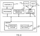
- FIG. 4 illustrates an example of components of a device 100 which may be implemented as a form of a computing and/or electronic device.
- the computing device 100 comprises one or more processors 402 which may be microprocessors, controllers or any other suitable type of processors for processing computer executable instructions to control the operation of the apparatus 100.
- Platform software comprising an operating system 406 or any other suitable platform software may be provided on the apparatus to enable application software 408 to be executed on the device.
- a discrete charging IC 102 may contain logic to detect and/or negotiate direct charging capabilities. According to an embodiment, the discrete charging IC, if present, may be controlled by processor 402.
- Computer executable instructions may be provided using any computer-readable media that are accessible by the device 100.
- Computer-readable media may include, for example, computer storage media such as a memory 404 and communications media.
- Computer storage media, such as a memory 404 include volatile and non-volatile, removable and non-removable media implemented in any method or technology for storage of information such as computer readable instructions, data structures, program modules.
- Computer storage media include, but are not limited to, RAM, ROM, EPROM, EEPROM, flash memory or other memory technology, CD-ROM, digital versatile disks (DVD) or other optical storage, magnetic cassettes, magnetic tape, magnetic disk storage or other magnetic storage devices, or any other non-transmission medium that can be used to store information for access by a computing device.
- communication media may embody computer readable instructions, data structures, program modules, in a modulated data signal, such as a carrier wave, or other transport mechanism.
- a modulated data signal such as a carrier wave, or other transport mechanism.
- the computer storage medium (the memory 404) is shown within the device 100, it will be appreciated, by a person skilled in the art, that the storage may be distributed or located remotely and accessed via a network or other communication link (e.g. using a communication interface 412).
- the device 100 may comprise an input/output controller 414 arranged to output information to an output device 416 which may be separate from or integral to the device 100.
- the input/output controller 414 may also be arranged to receive and process an input from one or more input devices 418.
- the output device 416 may also act as the input device.
- the input/output controller 414 may also output data to devices other than the output device, e.g. a locally connected printing device.
- the negotiation and/or detection of direct charging capabilities of a charger 200 in device 100 for example as shown in FIG. 1 may be established with the features of FIG. 4 , for example the operating system 406 and the application software 408 working jointly, and executed by the processor 402.
- the functionality described herein, for example, detection and/or negotiation of direct charging, can be performed, at least in part, by one or more hardware logic components.
- illustrative types of hardware logic components include Field-programmable Gate Arrays (FPGAs), Program-specific Integrated Circuits (ASICs), Program-specific Standard Products (ASSPs), System-on-a-chip systems (SOCs), Complex Programmable Logic Devices (CPLDs), Graphics Processing Units (GPUs).
- FPGAs Field-programmable Gate Arrays
- ASICs Program-specific Integrated Circuits
- ASSPs Program-specific Standard Products
- SOCs System-on-a-chip systems
- CPLDs Complex Programmable Logic Devices
- GPUs Graphics Processing Units
- FIG. 5 illustrates, as a schematic flow chart, a method of direct charging in accordance with an embodiment.
- the process comprises operations 500, 501, 502, 503, 504 and 505.
- at least operation 500 of the process of FIG. 5 may be compiled into the program code 406,408.
- Operation 500 may include detecting and/or negotiating direct charging capabilities between the device 100 which has a battery to be charged and the charging device 200.
- the detection and/or negotiation operation may also include detecting direct sense lines 109, 110, 209, 210.
- Operation 500 may further include exchange charging parameters and battery 104 characteristics.
- Operation 501 may include deciding whether to employ direct charging or not based on information from operation 500. If direct charging and sense lines 109, 110, 209, 210 are supported, operation 502 may be performed. Otherwise, operation 507 may be performed which may include conventional charging methods both direct and indirect.
- Operation 502 may include outputting a constant direct current for direct charging the battery 104.
- the output current and charging voltage levels may be based on battery characteristics.
- Operation 503 may include sensing the battery voltage, Vbatt, via sense lines from a battery 104.
- Operation 504 may include comparing the sensed battery voltage, Vbatt to a battery voltage target threshold, Vtarget. If the sensed battery voltage, Vbatt is greater than battery voltage target threshold, Vtarget, operation 505 may be performed, if not, the method may continue from operation 502.
- Operation 505 may include adjusting the output charging current and/or voltage so that Vbatt becomes less than or equal to Vtarget. According to an embodiment, this may also include switching to a constant voltage mode of charging.
- operations 503, 504 and 505 may be carried out fast enough to preclude the battery voltage from exceeding a battery voltage maximum threshold.
- the methods and functionalities described herein may be performed by software in machine readable form on a tangible storage medium e.g. in the form of a computer program comprising computer program code means adapted to perform all the functions and the steps of any of the methods described herein when the program is run on a computer and where the computer program may be embodied on a computer readable medium.
- tangible storage media include computer storage devices comprising computer-readable media such as disks, thumb drives, memory etc. and do not include propagated signals.
- the software can be suitable for execution on a parallel processor or a serial processor such that the method steps may be carried out in any suitable order, or simultaneously.
- FPGAs Field-programmable Gate Arrays
- ASICs Application-specific Integrated Circuits
- ASSPs Application-specific Standard Products
- SOCs System-on-a-chip systems
- CPLDs Complex Programmable Logic Devices
Landscapes
- Engineering & Computer Science (AREA)
- Power Engineering (AREA)
- Charge And Discharge Circuits For Batteries Or The Like (AREA)
Description
- Portable electronic devices need a power source to operate. Usually the power source is a battery. For ease of use and keeping the operating cost low, rechargeable batteries may be used. Rechargeable batteries may have multiple charging constraints for proper charging and maintaining a desired performance level. If these constraints are not followed during charging, the batteries may be damaged and/or cause damage to the device and even injure the user in extreme cases. Some of these constraints include maximum permissible charging voltage, target battery voltage, maximum permissible charging current, permissible battery temperature etc. These constraints may be interdependent and may necessitate charging the battery slowly over a long period of time. From a user's perspective faster charging may be desirable.
-
US 2008/231233 A1 discloses a device, comprising a battery, a battery charging circuit configured to allow direct charging of the battery by an external charging device, and a connector comprising: at least one sense wire coupled to the battery to sense battery voltage, and at least one wire coupled to the battery via the battery charging circuit configured to charge the battery. -
US 2009/ 189569 A1 describes a battery protection circuit inside a battery containing a device as a supplementary safety measure. -
CN 105098945 A discloses a method, comprising: outputting a constant current for direct charging a battery, sensing a battery voltage by sense lines from a battery, and reducing a charging current if the sensed battery voltage is greater than a battery voltage target threshold, the reduction being such that a battery voltage is precluded from exceeding a predefined battery voltage maximum threshold. -
US 2015/270733 A1 discloses a concept of connecting via a USB connecter type C a host device and an accessory device for charging purposes. - The present invention provides a device according to claim 1.
- The present invention also provides a device according to claim 8.
- The present invention also provides a method according to claim 13.
- Many of the attendant features will be more readily appreciated as they become better understood by reference to the following detailed description considered in connection with the accompanying drawings.
- The present description will be better understood from the following detailed description read in light of the accompanying drawings, wherein:
-
FIG. 1 illustrates a schematic representation of a charger and a device comprising a battery connected by a cable, according to an embodiment; -
FIG. 2 illustrates a graphical representation of various currents and voltages involved when sense lines are not used; -
FIG. 3 illustrates a graphical representation of various currents and voltages involved when sense lines are used, according to an embodiment; -
FIG.4 illustrates a computing device configured for direct charging, according to an embodiment; and -
FIG. 5 illustrates a schematic flow chart of a method of charging a battery in accordance with an embodiment. - Like references are used to designate like parts in the accompanying drawings.
- Although the embodiments may be described and illustrated herein as being implemented in a smartphone and a wall charger, this is only an example implementation and not a limitation. As those skilled in the art will appreciate, the present embodiments are suitable for application in a variety of different types of rechargeable battery operated devices, for example, laptops, tablet computers, phablets, mobile phones, cordless phones, portable media players, portable gaming consoles, portable barcode readers, portable point of sale devices etc. and charging devices comprising a direct current power source, for example a power bank, a device docking station etc.
- According to an embodiment, a battery may be charged by bypassing the on device charging control circuit, for example, by using a low resistance switch. In addition to voltage and ground lines configured to connect to the battery through a protection circuit, two battery voltage sense lines may also be configured to be connected to the battery to sense the battery voltage continuously. The voltage, ground and sense lines may be connected to a wall charger which may adjust its output voltage and output current according to a sensed battery voltage. According to an embodiment, when a battery is being charged in a constant current mode, some of the charging may be used to drive a system load of the device. When, and if the system load drops, all the charging current may be fed to the battery raising its voltage. The charger may receive the sensed battery voltage immediately and adjust the output voltage and output current suitably. This may prevent the battery voltage from rising above a battery voltage maximum threshold, preventing damage to the battery and improving its lifetime, capacity and or performance. According to an embodiment, safe and fast direct charging may be achieved. According to an embodiment, Side band use, SBU, pins/lines of a Universal serial bus USB Type C connector may be configured as sense lines whereas its Vbus and GND pins/lines may be used for delivering charge. According to an embodiment, configuration of SBU pins and lines for battery voltage sensing may not preclude the SBU pins/lines from being used for other purposes. According to an embodiment, charging device may be able to respond to an increase in battery voltage faster than for example, by using relatively time consuming protocols like polling the battery to know the voltage across its terminals.
-
FIG. 1 illustrates adevice 100, acharger 200 connected via a connectingcable 300, according to an embodiment. Thedevice 100 comprises abattery 104, aconnector 101 and a battery charging integratedcircuit 102, which may hereinafter be referred as charging IC, battery charger IC, battery charging IC, or a battery charging chip interchangeably. The battery charging IC may be configured to charge a battery according to some charging algorithms. It may, however, have the ability to relinquish charging control to a charger after a direct charging charger is detected.Battery 104 may compriseprotection circuitry 1041 and at least onerechargeable cell 1040.Connector 101 may comprise wires, for example pins corresponding to the charging line—Voltage bus,Vbus 107,ground line GND 108, and twosense lines connector 101 may be a USB Type C connector. According to an embodiment,connector 101 may be a custom charging connector. From theconnector 101,Vbus line 107 may connect to thecharging IC 102,GND line 108 may directly connect to aGND line 113 coming out of chargingIC 102.Sense lines battery 104 orcell 1040 to sense the battery voltage. From thebattery charging IC 102, VBAT 111 andGND 113 may connect to the cell terminals viaprotection circuit 1041, wherein VBAT 111 is the line carrying voltage tobattery 104. Other lines, likeID line 112 may also be connected between thebattery charging circuit 102 and thebattery protection circuit 1041. For direct charging, Vbus 107 from connector may be directly connected to VBAT 111 of the charging IC, for example, via a low resistance switch. According to an embodiment, the low resistance switch may be closed after the charging IC detects a compatibledirect charger 200. This may be accomplished by negotiations betweendevice 100 andcharger 200 or by a hardware ID or by a combination of both. According to an embodiment, if compatibility is not established, an alternative mode of charging may be used. Alternative modes of charging may include conventional indirect charging, direct charging without sense lines, software controlled direct charging, etc. -
Wall charger 200 comprises aconnector 201, afeedback circuit 205 and an alternating current, AC to direct current,DC converter 202 which supplies direct current DC for charging a battery. The AC-DC converter 202 may be able to supply current and voltage at specified values depending upon mode of charging. Theconnector 201 may comprise pins corresponding to charging line—Voltage bus Vbus 207,ground GND 208 and twosense lines Vbus line 207 may connect the Vbus pin to the AC-DC converter 202,GND line 208 may connect the GND pin to the AC-DC converter 202.Sense lines feedback circuit 205.Feedback circuit 205 may be connected to theVbus line 207, theGND line 208 and the AC-DC converter circuit 202.Further feedback circuit 205 may be connected to the AC-DC converter circuit 202 via aline 203.Line 203 may carry control signals to adjust output of AC-DC converter 202 fromfeedback circuit 205 based on sensed voltage onsense lines feedback circuit 205 may be wholly or partially contained within the AC-DC converter circuit 202. The connecting cable may comprise lines corresponding to Vbus, GND, and lines for sensing (not shown). At its ends it may compriseconnectors 301 and 301' configured to connect toconnector connectors 301 and 301' may be interchangeable or orientation agnostic or both interchangeable and orientation agnostic. According to an embodiment, connector 301' may be configured to be permanently connected toconnector 201. According to an embodiment,connectors 201 and 301' may be replaced by direct electric connections betweenlines wall charger 200 and lines in connectingcable 300. Although the present embodiments may be illustrated as being implemented using an AC-DC converter 202, it is for illustrative purposes only and not a limitation. According to an embodiment, AC-DC converter 202 may be replaced by a DC-DC converter (not shown). - Referring to
FIG. 1 , whendevice 100 is connected to wallcharger 200 via the connecting cable,device 100 may determine whetherwall charger 200 supports direct charging as specified herein. This may be accomplished, for example, by negotiations between thedevice 100 andcharger 200. According to an embodiment,connectors cable 300 may be USB type C compliant and the negotiation may take place over a USB or USB based connection, for example Alternate Mode as described in USB Power Delivery, USB PD specifications. According to an embodiment, thedevice 100 may determine that thewall charger 200 supports direct charging as specified herein by detecting an analog signal or a special pin inconnector 301. If direct charging as disclosed herein is supported, the chargingIC 102 may close a low resistance switch betweenVbus line 107 from theconnector 101 toVBAT line 111 to the battery, allowing a direct charging path from thecharger 200 to thebattery 104. The sense lines 209, 210 and 109, 110 may also form a direct sensing path from thewall charger 200 to thebattery 104 and/orcell 1040 via thecable 300. When thebattery 104 and/orcell 1040 voltage is below a battery voltage target threshold, the AC-DC converter 202 may supply a constant current to thebattery 104 for charging it. A portion of the current so supplied may be used to drive the system load. System load may include driving processors, or other integrated circuits, speakers, displays, sensors etc. (not shown inFIG. 1 ) indevice 100. At times the system load may drop and the portion of current driving the system load may be directed towards the battery, causing the battery voltage to rise. Thefeedback circuit 205 may detect the rise in battery voltage over sense lines and cause the AC-DC converter to output a lower current and/or charging voltage, so that battery voltage does not overshoot a battery voltage maximum threshold and quickly drops to a battery voltage target threshold. According to an embodiment, when the feedback circuit senses a rise in battery voltage towards the battery voltage target threshold or battery voltage maximum threshold, the charging is changed to a constant voltage mode. According to an embodiment, battery voltage maximum threshold and battery voltage target threshold may be based onbattery 104 characteristics. According to an embodiment, battery voltage maximum threshold may be the maximum battery voltage which does not affect thebattery 104 or thedevice 100 adversely. According to an embodiment, battery voltage target threshold may be a voltage at which thebattery 104 operates and/or charges optimally. According to an embodiment, factors affecting thebattery 104 anddevice 100 may also be considered while defining the battery voltage target threshold and battery voltage maximum threshold. - According to an embodiment,
battery 104 may be charged safely and quickly. According to an embodiment, voltage drop across the connectingcable 300 and other components between the AC-DC converter 202 andbattery 104 and/orcell 1040 may be compensated. According to an embodiment, life and capacity ofbattery 104 may be improved by preventing battery voltage from rising above the battery voltage maximum threshold. According to an embodiment, response of AC-DC converter 202 to change in battery voltage due to sensing by sense lines may be faster than, for example, a scenario where charging control is software based. -
FIG 2 andFIG 3 respectively illustrate direct charging without and withsense lines battery 104 to thewall charger 200, in a graphical form, according to an embodiment. Referring toFIG 2 andFIG 3 ,battery voltage 20, battery voltagemaximum threshold 21, batteryvoltage target threshold 22, charger current 25, battery current 26 and systemcurrent consumption 27 are exemplarily plotted with respect to time. - Referring to
FIG. 2 , initially thebattery 104 may be charged in a constant current mode, the charger current 25 being constant. Some of the charger current 25 may be utilized to drive the system load. This current is represented by the systemcurrent consumption line 27. The rest of the current supplied by the charger, may charge thebattery 104 and is represented bybattery current 26. Initially the system load current 27 and battery current 26 may be constant hence thebattery voltage 20 may be steady and below the batteryvoltage target threshold 22, and the battery voltagemaximum threshold 21. At an exemplary point T in time, the system usage and hence the systemcurrent consumption 27 may drop. Since the charger current is constant, all the current may be directed to the battery causing thebattery current 26 and hence thebattery voltage 20 to rise. If the change in battery current is substantial, thebattery voltage 20 may rise above the battery voltagemaximum threshold 21, damaging thebattery 104 and possibly thedevice 100. In some cases, this may cause battery overheating, expansion, decrease in battery performance, decrease in usable battery lifetime, or other undesired effects. -
FIG. 3 represents the same system current consumption scenario as illustrated inFIG 2 , but illustrates the effect of usingsense lines feedback unit 205 via the sense lines and current and/or voltage output of 202 may be promptly reduced. This may prevent thebattery voltage 20 from rising above the battery voltagemaximum threshold 21. Thebattery voltage 20 may be quickly brought down to a batteryvoltage target threshold 22 by adjusting the output current of thecharger 200. -
FIG. 4 illustrates an example of components of adevice 100 which may be implemented as a form of a computing and/or electronic device. Thecomputing device 100 comprises one ormore processors 402 which may be microprocessors, controllers or any other suitable type of processors for processing computer executable instructions to control the operation of theapparatus 100. Platform software comprising anoperating system 406 or any other suitable platform software may be provided on the apparatus to enableapplication software 408 to be executed on the device. There may be aseparate charging IC 102 or the charging IC may be integral toprocessor 402. Adiscrete charging IC 102 may contain logic to detect and/or negotiate direct charging capabilities. According to an embodiment, the discrete charging IC, if present, may be controlled byprocessor 402. - Computer executable instructions may be provided using any computer-readable media that are accessible by the
device 100. Computer-readable media may include, for example, computer storage media such as amemory 404 and communications media. Computer storage media, such as amemory 404, include volatile and non-volatile, removable and non-removable media implemented in any method or technology for storage of information such as computer readable instructions, data structures, program modules. Computer storage media include, but are not limited to, RAM, ROM, EPROM, EEPROM, flash memory or other memory technology, CD-ROM, digital versatile disks (DVD) or other optical storage, magnetic cassettes, magnetic tape, magnetic disk storage or other magnetic storage devices, or any other non-transmission medium that can be used to store information for access by a computing device. In contrast, communication media may embody computer readable instructions, data structures, program modules, in a modulated data signal, such as a carrier wave, or other transport mechanism. Although the computer storage medium (the memory 404) is shown within thedevice 100, it will be appreciated, by a person skilled in the art, that the storage may be distributed or located remotely and accessed via a network or other communication link (e.g. using a communication interface 412). - The
device 100 may comprise an input/output controller 414 arranged to output information to anoutput device 416 which may be separate from or integral to thedevice 100. The input/output controller 414 may also be arranged to receive and process an input from one ormore input devices 418. In one embodiment, theoutput device 416 may also act as the input device. The input/output controller 414 may also output data to devices other than the output device, e.g. a locally connected printing device. According to an embodiment, the negotiation and/or detection of direct charging capabilities of acharger 200 indevice 100 for example as shown inFIG. 1 , may be established with the features ofFIG. 4 , for example theoperating system 406 and theapplication software 408 working jointly, and executed by theprocessor 402. - The functionality described herein, for example, detection and/or negotiation of direct charging, can be performed, at least in part, by one or more hardware logic components. For example, and without limitation, illustrative types of hardware logic components that can be used include Field-programmable Gate Arrays (FPGAs), Program-specific Integrated Circuits (ASICs), Program-specific Standard Products (ASSPs), System-on-a-chip systems (SOCs), Complex Programmable Logic Devices (CPLDs), Graphics Processing Units (GPUs).
-
FIG. 5 illustrates, as a schematic flow chart, a method of direct charging in accordance with an embodiment. Referring toFIG. 5 , according to an embodiment the process comprisesoperations least operation 500 of the process ofFIG. 5 may be compiled into the program code 406,408. -
Operation 500 may include detecting and/or negotiating direct charging capabilities between thedevice 100 which has a battery to be charged and thecharging device 200. The detection and/or negotiation operation may also include detectingdirect sense lines Operation 500 may further include exchange charging parameters andbattery 104 characteristics. -
Operation 501 may include deciding whether to employ direct charging or not based on information fromoperation 500. If direct charging andsense lines operation 502 may be performed. Otherwise,operation 507 may be performed which may include conventional charging methods both direct and indirect. -
Operation 502 may include outputting a constant direct current for direct charging thebattery 104. The output current and charging voltage levels may be based on battery characteristics. -
Operation 503 may include sensing the battery voltage, Vbatt, via sense lines from abattery 104. -
Operation 504 may include comparing the sensed battery voltage, Vbatt to a battery voltage target threshold, Vtarget. If the sensed battery voltage, Vbatt is greater than battery voltage target threshold, Vtarget,operation 505 may be performed, if not, the method may continue fromoperation 502. -
Operation 505 may include adjusting the output charging current and/or voltage so that Vbatt becomes less than or equal to Vtarget. According to an embodiment, this may also include switching to a constant voltage mode of charging. - According to an embodiment,
operations - The methods and functionalities described herein may be performed by software in machine readable form on a tangible storage medium e.g. in the form of a computer program comprising computer program code means adapted to perform all the functions and the steps of any of the methods described herein when the program is run on a computer and where the computer program may be embodied on a computer readable medium. Examples of tangible storage media include computer storage devices comprising computer-readable media such as disks, thumb drives, memory etc. and do not include propagated signals. The software can be suitable for execution on a parallel processor or a serial processor such that the method steps may be carried out in any suitable order, or simultaneously.
- This acknowledges that software can be a valuable, separately tradable commodity. It is intended to encompass software, which runs on or controls "dumb" or standard hardware, to carry out the desired functions. It is also intended to encompass software which "describes" or defines the configuration of hardware, such as HDL (hardware description language) software, as is used for designing silicon chips, or for configuring universal programmable chips, to carry out desired functions. Alternatively, or in addition, the functionally described herein can be performed, at least in part, by one or more hardware logic components. For example, and without limitation, illustrative types of hardware logic components that can be used include Field-programmable Gate Arrays (FPGAs), Application-specific Integrated Circuits (ASICs), Application-specific Standard Products (ASSPs), System-on-a-chip systems (SOCs), Complex Programmable Logic Devices (CPLDs), etc.
Claims (14)
- A device (100), comprising:a battery (104);a battery charging circuit (102) configured to allow direct charging of the battery (104) by an external charging device (200);a battery protection circuit (1041) configured to protect the battery (104) from electrical damage, coupled to the battery charging circuit (102); anda connector (101) comprising:at least one sense wire (109, 110) coupled to the battery (104) to sense battery voltage; and at least one wire (107) coupled to the battery (104) via the battery charging circuit (102)and the battery protection circuit (1041), configured to charge the battery (104), wherein the connector (101) comprises a Universal Serial Bus, USB, Type-C connector andwherein Sideband Use, SBU, pins are configured to sense the battery voltage.
- The device (100) of claim 1, further comprising a low resistance switch for direct charging the battery (104), wherein the switch is controlled by the battery charging circuit (102).
- The device (100) of claim 1, wherein the connector (101) further comprises wires for data communication.
- The device (100) of claim 1, wherein charging capabilities are negotiated between the device (100) and the external charging device (200) before charging commences.
- The device (100) of claim 1, wherein if the at least one sense wire is not connected to the external charging device, an alternative mode of charging is selected.
- The device (100) of claim 5, wherein the alternative mode of charging comprises direct charging without direct sense wires.
- The device (100) of claim 7, wherein Voltage Bus pin, Vbus (107), and Ground pin, GND(108), are configured to charge the battery (104).
- A device (200) comprising:a power supply;a feedback circuit (205);a connector (201) comprising:at least one sense pin (209, 210) coupled to the power supply via the feedback circuit (205), configured to receive a sensed voltage of a battery (104) to be charged; andat least one pin (207) coupled to the power supply, configured to carry a charging current for direct charging the battery (104);wherein the charging parameters are adjusted based on the sensed battery voltage on the sense pin and, wherein the connector (101) comprises a Universal Serial Bus, USB, Type-C connector and wherein Sideband Use, SBU, pins are configured to sense the battery voltage.
- The device (200) of claim 8, wherein the charging mode is changed from a constant current mode to a constant voltage mode if the sensed voltage is above a battery voltage target threshold.
- The device (200) of claim 8, wherein the charging current is reduced if the sensed battery voltage rises above a predefined battery voltage target threshold.
- The device (200) of claim 10, wherein the reduction in the charging current is such that the battery voltage is precluded from exceeding a predefined battery voltage maximum threshold and drops to a battery voltage target threshold.
- The device (200) of claim 8, wherein the feedback circuit (205) comprises wholly or partially integral to the power supply.
- A method, comprising:outputting (502), via a connector (101), a constant current for direct charging a battery (104);sensing (503) a battery voltage by sense lines (109, 110) from a battery (104); andreducing (505) a charging current if the sensed battery voltage is greater than a battery voltage target threshold, the reduction being such that the battery voltage is precluded from exceeding a predefined battery voltage maximum threshold, and wherein the connector (101) comprises a Universal Serial Bus, USB, Type-C connector and wherein Sideband Use, SBU, pins are configured to sense the battery voltage.
- The method of claim 13, wherein before commencement of direct charging, direct charging (501) capabilities and/or parameters are negotiated with the device to be charged.
Applications Claiming Priority (2)
| Application Number | Priority Date | Filing Date | Title |
|---|---|---|---|
| US15/096,237 US10044201B2 (en) | 2016-04-11 | 2016-04-11 | Smart senses for direct charging |
| PCT/US2017/025812 WO2017180354A1 (en) | 2016-04-11 | 2017-04-04 | Smart senses for direct charging |
Publications (2)
| Publication Number | Publication Date |
|---|---|
| EP3443634A1 EP3443634A1 (en) | 2019-02-20 |
| EP3443634B1 true EP3443634B1 (en) | 2021-12-08 |
Family
ID=58610000
Family Applications (1)
| Application Number | Title | Priority Date | Filing Date |
|---|---|---|---|
| EP17719080.8A Active EP3443634B1 (en) | 2016-04-11 | 2017-04-04 | Smart senses for direct charging |
Country Status (4)
| Country | Link |
|---|---|
| US (1) | US10044201B2 (en) |
| EP (1) | EP3443634B1 (en) |
| CN (1) | CN109075586B (en) |
| WO (1) | WO2017180354A1 (en) |
Families Citing this family (9)
| Publication number | Priority date | Publication date | Assignee | Title |
|---|---|---|---|---|
| WO2018032274A1 (en) * | 2016-08-15 | 2018-02-22 | 北京小米移动软件有限公司 | Electronic device, charger, charging system and charging method |
| US20180254648A1 (en) * | 2017-03-01 | 2018-09-06 | Dialog Semiconductor (Uk) Limited | Applying Alternate Modes of USB Type-C for Fast Charging Systems |
| TWI612750B (en) * | 2017-03-22 | 2018-01-21 | Asustek Computer Inc. | Electronic device and charging method thereof |
| EP3477810A1 (en) * | 2017-10-30 | 2019-05-01 | Vestel Elektronik Sanayi ve Ticaret A.S. | Method of operating an electronic device, electronic device and computer program |
| WO2019113732A1 (en) * | 2017-12-11 | 2019-06-20 | 深圳市柔宇科技有限公司 | Electronic device and charging control method |
| US10317969B1 (en) * | 2018-04-27 | 2019-06-11 | Cypress Semiconductor Corporation | Dynamic VCONN swapping in dual-powered type-C cable applications |
| CN110492562B (en) * | 2019-08-16 | 2020-11-24 | 珠海格力电器股份有限公司 | Mobile power supply equipment and its power supply control method, device, and power supply equipment |
| US20230409097A1 (en) * | 2022-06-15 | 2023-12-21 | Hewlett-Packard Development Company, L.P. | Battery charging control through universal serial bus (usb) interfaces |
| CN117849597B (en) * | 2024-03-08 | 2024-07-09 | 荣耀终端有限公司 | Circuit board test equipment |
Citations (1)
| Publication number | Priority date | Publication date | Assignee | Title |
|---|---|---|---|---|
| US20150270733A1 (en) * | 2014-03-24 | 2015-09-24 | Nokia Corporation | Device to device charging via usb type-c interfaces |
Family Cites Families (23)
| Publication number | Priority date | Publication date | Assignee | Title |
|---|---|---|---|---|
| US20080231233A1 (en) | 2001-12-03 | 2008-09-25 | Walter Thornton | Power converter including auxiliary battery charger |
| US7449865B2 (en) | 2004-11-29 | 2008-11-11 | Mediatek Incorporation | Battery charger for preventing both overshoot charging currents and overcharged battery voltage during mode transitions and method thereof |
| US7843171B2 (en) * | 2008-01-21 | 2010-11-30 | Semtech Corporation | Method and apparatus for battery charging based on battery capacity and charging source constraints |
| US8541984B2 (en) | 2008-01-28 | 2013-09-24 | Mediatek Inc. | Charging systems capable of determining the kind of coupled device and related methods thereof |
| US8350522B2 (en) | 2010-03-10 | 2013-01-08 | Apple Inc. | External power source voltage drop compensation for portable devices |
| US8717044B2 (en) | 2010-04-23 | 2014-05-06 | Apple Inc. | Charging systems with direct charging port support and extended capabilities |
| US8441235B2 (en) * | 2011-01-31 | 2013-05-14 | Taiwan Semiconductor Manufacturing Company, Ltd. | Battery charger digital control circuit and method |
| KR101201811B1 (en) | 2011-03-15 | 2012-11-15 | 삼성에스디아이 주식회사 | Charging and discharging device |
| WO2014145756A1 (en) | 2013-03-15 | 2014-09-18 | Design Flux Technologies, Llc | Method and apparatus for creating a dynamically reconfigurable energy storage device |
| EP2989695A4 (en) | 2013-04-22 | 2016-11-30 | Mediatek Inc | Method for communicating electronic apparatus with adaptor via specific communication interface to adjust operation behavior of adaptor, electronic apparatus, and corresponding adaptor |
| US8749193B1 (en) * | 2013-05-10 | 2014-06-10 | Inpower Llc | Battery protection circuit for multiple battery power supply and charging system |
| CN104253461B (en) | 2013-06-28 | 2016-12-28 | 华为终端有限公司 | A kind of charger and the method for supplying power to of charger |
| CN103475068B (en) | 2013-09-30 | 2016-03-23 | 小米科技有限责任公司 | A kind of charger, charging terminal, charging system and charge control method |
| CN204067514U (en) | 2014-01-21 | 2014-12-31 | 深圳市金立通信设备有限公司 | Device, terminal, charger and system for activating battery |
| CN108134432B (en) | 2014-01-28 | 2021-01-15 | Oppo广东移动通信有限公司 | Electronic equipment charging control device and method |
| CN203747454U (en) | 2014-01-28 | 2014-07-30 | 广东欧珀移动通信有限公司 | Electronic equipment charging control device |
| CN104467077A (en) | 2014-11-14 | 2015-03-25 | 合肥正美电源科技有限公司 | Storage battery charging control method |
| CN104779667B (en) * | 2015-03-25 | 2017-11-07 | 深圳市华宝新能源股份有限公司 | Portable power source |
| CN105098945B (en) | 2015-08-05 | 2018-01-09 | 青岛海信移动通信技术股份有限公司 | One kind can directly charge source adapter |
| CN204947285U (en) * | 2015-08-05 | 2016-01-06 | 庄忆芳 | USB Type-C conversion module |
| CN205139907U (en) * | 2015-08-05 | 2016-04-06 | 东莞铭基电子科技集团有限公司 | A USB Type-C data cable |
| CN204992666U (en) * | 2015-08-07 | 2016-01-20 | 马魁元 | Vehicle -mounted charger |
| US10148108B2 (en) * | 2015-10-29 | 2018-12-04 | Intel Corporation | Battery charger with USB type-C adapter |
-
2016
- 2016-04-11 US US15/096,237 patent/US10044201B2/en active Active
-
2017
- 2017-04-04 CN CN201780023122.4A patent/CN109075586B/en active Active
- 2017-04-04 WO PCT/US2017/025812 patent/WO2017180354A1/en not_active Ceased
- 2017-04-04 EP EP17719080.8A patent/EP3443634B1/en active Active
Patent Citations (1)
| Publication number | Priority date | Publication date | Assignee | Title |
|---|---|---|---|---|
| US20150270733A1 (en) * | 2014-03-24 | 2015-09-24 | Nokia Corporation | Device to device charging via usb type-c interfaces |
Also Published As
| Publication number | Publication date |
|---|---|
| US20170294789A1 (en) | 2017-10-12 |
| EP3443634A1 (en) | 2019-02-20 |
| CN109075586B (en) | 2021-10-15 |
| WO2017180354A1 (en) | 2017-10-19 |
| CN109075586A (en) | 2018-12-21 |
| US10044201B2 (en) | 2018-08-07 |
Similar Documents
| Publication | Publication Date | Title |
|---|---|---|
| US10044201B2 (en) | Smart senses for direct charging | |
| KR102710698B1 (en) | Electronic device and method for transmitting wireless power based on detecting foreign object in electronic device | |
| KR102692156B1 (en) | An electronic apparatus and a method for controlling voltage output to an external electronic device according to voltage sensed at a signal terminal connected to the external electronic device | |
| US10978896B2 (en) | High efficiency power storage adapter | |
| US10381844B2 (en) | Sourcing power from a battery or AC-DC converter of a power storage adapter | |
| EP3043442B1 (en) | Hub having complex power converters | |
| US10389154B2 (en) | Power storage adapter using a high efficiency charging method | |
| DK1595324T3 (en) | Circuits and operating procedures for an electric power supply | |
| US10181739B1 (en) | Power storage adapter using high efficiency charging for low power states | |
| TWI568136B (en) | Equipment, electronic devices and non-transitory computer readable media for providing electricity | |
| US20190064914A1 (en) | Power storage adapter for efficient supply of power of multiple portable information handling systems | |
| US9634502B2 (en) | Fast battery charging through digital feedback | |
| US10181731B1 (en) | Combining power from a battery and an AC-DC converter of a power storage adapter | |
| US20180375361A1 (en) | Low standby power in a power storage adapter enabled by an associated battery | |
| US11513928B2 (en) | Power storage adapter with power cable validation | |
| KR102455442B1 (en) | Electronic apparatus and method for controlling power supply of the same | |
| KR102651715B1 (en) | Electronic device for preventing damage of usb device and operating method thereof | |
| CN113383479A (en) | Electronic device for wirelessly charging external device | |
| CN106797414B (en) | A terminal leakage current detection circuit and terminal | |
| TWI492039B (en) | Power management module and power supply apparatus | |
| US20170063105A1 (en) | Charging method, charging controller and charging system | |
| KR101028245B1 (en) | Mobile communication terminal | |
| KR102600482B1 (en) | Electronic apparatus and method for outputting a alarm, and system including a locking device connected to the electronic device | |
| JP6442765B2 (en) | Information processing apparatus, charge control method, and charge control program | |
| CN106532790B (en) | Mobile power supply device and power supply control method thereof |
Legal Events
| Date | Code | Title | Description |
|---|---|---|---|
| STAA | Information on the status of an ep patent application or granted ep patent |
Free format text: STATUS: UNKNOWN |
|
| STAA | Information on the status of an ep patent application or granted ep patent |
Free format text: STATUS: THE INTERNATIONAL PUBLICATION HAS BEEN MADE |
|
| PUAI | Public reference made under article 153(3) epc to a published international application that has entered the european phase |
Free format text: ORIGINAL CODE: 0009012 |
|
| STAA | Information on the status of an ep patent application or granted ep patent |
Free format text: STATUS: REQUEST FOR EXAMINATION WAS MADE |
|
| 17P | Request for examination filed |
Effective date: 20181010 |
|
| AK | Designated contracting states |
Kind code of ref document: A1 Designated state(s): AL AT BE BG CH CY CZ DE DK EE ES FI FR GB GR HR HU IE IS IT LI LT LU LV MC MK MT NL NO PL PT RO RS SE SI SK SM TR |
|
| AX | Request for extension of the european patent |
Extension state: BA ME |
|
| DAV | Request for validation of the european patent (deleted) | ||
| DAX | Request for extension of the european patent (deleted) | ||
| STAA | Information on the status of an ep patent application or granted ep patent |
Free format text: STATUS: EXAMINATION IS IN PROGRESS |
|
| 17Q | First examination report despatched |
Effective date: 20201215 |
|
| GRAP | Despatch of communication of intention to grant a patent |
Free format text: ORIGINAL CODE: EPIDOSNIGR1 |
|
| STAA | Information on the status of an ep patent application or granted ep patent |
Free format text: STATUS: GRANT OF PATENT IS INTENDED |
|
| INTG | Intention to grant announced |
Effective date: 20210630 |
|
| GRAS | Grant fee paid |
Free format text: ORIGINAL CODE: EPIDOSNIGR3 |
|
| GRAA | (expected) grant |
Free format text: ORIGINAL CODE: 0009210 |
|
| STAA | Information on the status of an ep patent application or granted ep patent |
Free format text: STATUS: THE PATENT HAS BEEN GRANTED |
|
| RAP3 | Party data changed (applicant data changed or rights of an application transferred) |
Owner name: MICROSOFT TECHNOLOGY LICENSING, LLC |
|
| AK | Designated contracting states |
Kind code of ref document: B1 Designated state(s): AL AT BE BG CH CY CZ DE DK EE ES FI FR GB GR HR HU IE IS IT LI LT LU LV MC MK MT NL NO PL PT RO RS SE SI SK SM TR |
|
| REG | Reference to a national code |
Ref country code: GB Ref legal event code: FG4D |
|
| REG | Reference to a national code |
Ref country code: AT Ref legal event code: REF Ref document number: 1454477 Country of ref document: AT Kind code of ref document: T Effective date: 20211215 Ref country code: CH Ref legal event code: EP |
|
| REG | Reference to a national code |
Ref country code: DE Ref legal event code: R096 Ref document number: 602017050557 Country of ref document: DE |
|
| REG | Reference to a national code |
Ref country code: IE Ref legal event code: FG4D |
|
| REG | Reference to a national code |
Ref country code: LT Ref legal event code: MG9D |
|
| REG | Reference to a national code |
Ref country code: NL Ref legal event code: MP Effective date: 20211208 |
|
| PG25 | Lapsed in a contracting state [announced via postgrant information from national office to epo] |
Ref country code: RS Free format text: LAPSE BECAUSE OF FAILURE TO SUBMIT A TRANSLATION OF THE DESCRIPTION OR TO PAY THE FEE WITHIN THE PRESCRIBED TIME-LIMIT Effective date: 20211208 Ref country code: LT Free format text: LAPSE BECAUSE OF FAILURE TO SUBMIT A TRANSLATION OF THE DESCRIPTION OR TO PAY THE FEE WITHIN THE PRESCRIBED TIME-LIMIT Effective date: 20211208 Ref country code: FI Free format text: LAPSE BECAUSE OF FAILURE TO SUBMIT A TRANSLATION OF THE DESCRIPTION OR TO PAY THE FEE WITHIN THE PRESCRIBED TIME-LIMIT Effective date: 20211208 Ref country code: BG Free format text: LAPSE BECAUSE OF FAILURE TO SUBMIT A TRANSLATION OF THE DESCRIPTION OR TO PAY THE FEE WITHIN THE PRESCRIBED TIME-LIMIT Effective date: 20220308 |
|
| REG | Reference to a national code |
Ref country code: AT Ref legal event code: MK05 Ref document number: 1454477 Country of ref document: AT Kind code of ref document: T Effective date: 20211208 |
|
| PG25 | Lapsed in a contracting state [announced via postgrant information from national office to epo] |
Ref country code: SE Free format text: LAPSE BECAUSE OF FAILURE TO SUBMIT A TRANSLATION OF THE DESCRIPTION OR TO PAY THE FEE WITHIN THE PRESCRIBED TIME-LIMIT Effective date: 20211208 Ref country code: NO Free format text: LAPSE BECAUSE OF FAILURE TO SUBMIT A TRANSLATION OF THE DESCRIPTION OR TO PAY THE FEE WITHIN THE PRESCRIBED TIME-LIMIT Effective date: 20220308 Ref country code: LV Free format text: LAPSE BECAUSE OF FAILURE TO SUBMIT A TRANSLATION OF THE DESCRIPTION OR TO PAY THE FEE WITHIN THE PRESCRIBED TIME-LIMIT Effective date: 20211208 Ref country code: HR Free format text: LAPSE BECAUSE OF FAILURE TO SUBMIT A TRANSLATION OF THE DESCRIPTION OR TO PAY THE FEE WITHIN THE PRESCRIBED TIME-LIMIT Effective date: 20211208 Ref country code: GR Free format text: LAPSE BECAUSE OF FAILURE TO SUBMIT A TRANSLATION OF THE DESCRIPTION OR TO PAY THE FEE WITHIN THE PRESCRIBED TIME-LIMIT Effective date: 20220309 Ref country code: ES Free format text: LAPSE BECAUSE OF FAILURE TO SUBMIT A TRANSLATION OF THE DESCRIPTION OR TO PAY THE FEE WITHIN THE PRESCRIBED TIME-LIMIT Effective date: 20211208 |
|
| PG25 | Lapsed in a contracting state [announced via postgrant information from national office to epo] |
Ref country code: NL Free format text: LAPSE BECAUSE OF FAILURE TO SUBMIT A TRANSLATION OF THE DESCRIPTION OR TO PAY THE FEE WITHIN THE PRESCRIBED TIME-LIMIT Effective date: 20211208 |
|
| PG25 | Lapsed in a contracting state [announced via postgrant information from national office to epo] |
Ref country code: SM Free format text: LAPSE BECAUSE OF FAILURE TO SUBMIT A TRANSLATION OF THE DESCRIPTION OR TO PAY THE FEE WITHIN THE PRESCRIBED TIME-LIMIT Effective date: 20211208 Ref country code: SK Free format text: LAPSE BECAUSE OF FAILURE TO SUBMIT A TRANSLATION OF THE DESCRIPTION OR TO PAY THE FEE WITHIN THE PRESCRIBED TIME-LIMIT Effective date: 20211208 Ref country code: RO Free format text: LAPSE BECAUSE OF FAILURE TO SUBMIT A TRANSLATION OF THE DESCRIPTION OR TO PAY THE FEE WITHIN THE PRESCRIBED TIME-LIMIT Effective date: 20211208 Ref country code: PT Free format text: LAPSE BECAUSE OF FAILURE TO SUBMIT A TRANSLATION OF THE DESCRIPTION OR TO PAY THE FEE WITHIN THE PRESCRIBED TIME-LIMIT Effective date: 20220408 Ref country code: EE Free format text: LAPSE BECAUSE OF FAILURE TO SUBMIT A TRANSLATION OF THE DESCRIPTION OR TO PAY THE FEE WITHIN THE PRESCRIBED TIME-LIMIT Effective date: 20211208 Ref country code: CZ Free format text: LAPSE BECAUSE OF FAILURE TO SUBMIT A TRANSLATION OF THE DESCRIPTION OR TO PAY THE FEE WITHIN THE PRESCRIBED TIME-LIMIT Effective date: 20211208 |
|
| PG25 | Lapsed in a contracting state [announced via postgrant information from national office to epo] |
Ref country code: PL Free format text: LAPSE BECAUSE OF FAILURE TO SUBMIT A TRANSLATION OF THE DESCRIPTION OR TO PAY THE FEE WITHIN THE PRESCRIBED TIME-LIMIT Effective date: 20211208 Ref country code: AT Free format text: LAPSE BECAUSE OF FAILURE TO SUBMIT A TRANSLATION OF THE DESCRIPTION OR TO PAY THE FEE WITHIN THE PRESCRIBED TIME-LIMIT Effective date: 20211208 |
|
| REG | Reference to a national code |
Ref country code: DE Ref legal event code: R097 Ref document number: 602017050557 Country of ref document: DE |
|
| PG25 | Lapsed in a contracting state [announced via postgrant information from national office to epo] |
Ref country code: IS Free format text: LAPSE BECAUSE OF FAILURE TO SUBMIT A TRANSLATION OF THE DESCRIPTION OR TO PAY THE FEE WITHIN THE PRESCRIBED TIME-LIMIT Effective date: 20220408 |
|
| PLBE | No opposition filed within time limit |
Free format text: ORIGINAL CODE: 0009261 |
|
| STAA | Information on the status of an ep patent application or granted ep patent |
Free format text: STATUS: NO OPPOSITION FILED WITHIN TIME LIMIT |
|
| PG25 | Lapsed in a contracting state [announced via postgrant information from national office to epo] |
Ref country code: DK Free format text: LAPSE BECAUSE OF FAILURE TO SUBMIT A TRANSLATION OF THE DESCRIPTION OR TO PAY THE FEE WITHIN THE PRESCRIBED TIME-LIMIT Effective date: 20211208 Ref country code: AL Free format text: LAPSE BECAUSE OF FAILURE TO SUBMIT A TRANSLATION OF THE DESCRIPTION OR TO PAY THE FEE WITHIN THE PRESCRIBED TIME-LIMIT Effective date: 20211208 |
|
| 26N | No opposition filed |
Effective date: 20220909 |
|
| PG25 | Lapsed in a contracting state [announced via postgrant information from national office to epo] |
Ref country code: SI Free format text: LAPSE BECAUSE OF FAILURE TO SUBMIT A TRANSLATION OF THE DESCRIPTION OR TO PAY THE FEE WITHIN THE PRESCRIBED TIME-LIMIT Effective date: 20211208 |
|
| REG | Reference to a national code |
Ref country code: CH Ref legal event code: PL |
|
| REG | Reference to a national code |
Ref country code: BE Ref legal event code: MM Effective date: 20220430 |
|
| PG25 | Lapsed in a contracting state [announced via postgrant information from national office to epo] |
Ref country code: MC Free format text: LAPSE BECAUSE OF FAILURE TO SUBMIT A TRANSLATION OF THE DESCRIPTION OR TO PAY THE FEE WITHIN THE PRESCRIBED TIME-LIMIT Effective date: 20211208 Ref country code: LU Free format text: LAPSE BECAUSE OF NON-PAYMENT OF DUE FEES Effective date: 20220404 Ref country code: LI Free format text: LAPSE BECAUSE OF NON-PAYMENT OF DUE FEES Effective date: 20220430 Ref country code: CH Free format text: LAPSE BECAUSE OF NON-PAYMENT OF DUE FEES Effective date: 20220430 |
|
| PG25 | Lapsed in a contracting state [announced via postgrant information from national office to epo] |
Ref country code: BE Free format text: LAPSE BECAUSE OF NON-PAYMENT OF DUE FEES Effective date: 20220430 |
|
| PG25 | Lapsed in a contracting state [announced via postgrant information from national office to epo] |
Ref country code: IE Free format text: LAPSE BECAUSE OF NON-PAYMENT OF DUE FEES Effective date: 20220404 |
|
| PG25 | Lapsed in a contracting state [announced via postgrant information from national office to epo] |
Ref country code: IT Free format text: LAPSE BECAUSE OF FAILURE TO SUBMIT A TRANSLATION OF THE DESCRIPTION OR TO PAY THE FEE WITHIN THE PRESCRIBED TIME-LIMIT Effective date: 20211208 |
|
| P01 | Opt-out of the competence of the unified patent court (upc) registered |
Effective date: 20230512 |
|
| PG25 | Lapsed in a contracting state [announced via postgrant information from national office to epo] |
Ref country code: HU Free format text: LAPSE BECAUSE OF FAILURE TO SUBMIT A TRANSLATION OF THE DESCRIPTION OR TO PAY THE FEE WITHIN THE PRESCRIBED TIME-LIMIT; INVALID AB INITIO Effective date: 20170404 |
|
| PG25 | Lapsed in a contracting state [announced via postgrant information from national office to epo] |
Ref country code: MK Free format text: LAPSE BECAUSE OF FAILURE TO SUBMIT A TRANSLATION OF THE DESCRIPTION OR TO PAY THE FEE WITHIN THE PRESCRIBED TIME-LIMIT Effective date: 20211208 Ref country code: CY Free format text: LAPSE BECAUSE OF FAILURE TO SUBMIT A TRANSLATION OF THE DESCRIPTION OR TO PAY THE FEE WITHIN THE PRESCRIBED TIME-LIMIT Effective date: 20211208 |
|
| PGFP | Annual fee paid to national office [announced via postgrant information from national office to epo] |
Ref country code: FR Payment date: 20240320 Year of fee payment: 8 |
|
| PG25 | Lapsed in a contracting state [announced via postgrant information from national office to epo] |
Ref country code: TR Free format text: LAPSE BECAUSE OF FAILURE TO SUBMIT A TRANSLATION OF THE DESCRIPTION OR TO PAY THE FEE WITHIN THE PRESCRIBED TIME-LIMIT Effective date: 20211208 |
|
| PG25 | Lapsed in a contracting state [announced via postgrant information from national office to epo] |
Ref country code: MT Free format text: LAPSE BECAUSE OF FAILURE TO SUBMIT A TRANSLATION OF THE DESCRIPTION OR TO PAY THE FEE WITHIN THE PRESCRIBED TIME-LIMIT Effective date: 20211208 |
|
| PGFP | Annual fee paid to national office [announced via postgrant information from national office to epo] |
Ref country code: DE Payment date: 20250319 Year of fee payment: 9 |
|
| PG25 | Lapsed in a contracting state [announced via postgrant information from national office to epo] |
Ref country code: FR Free format text: LAPSE BECAUSE OF NON-PAYMENT OF DUE FEES Effective date: 20250430 |
|
| PGFP | Annual fee paid to national office [announced via postgrant information from national office to epo] |
Ref country code: GB Payment date: 20260319 Year of fee payment: 10 |