EP3443336B1 - Electrochemical sensor - Google Patents
Electrochemical sensor Download PDFInfo
- Publication number
- EP3443336B1 EP3443336B1 EP17715261.8A EP17715261A EP3443336B1 EP 3443336 B1 EP3443336 B1 EP 3443336B1 EP 17715261 A EP17715261 A EP 17715261A EP 3443336 B1 EP3443336 B1 EP 3443336B1
- Authority
- EP
- European Patent Office
- Prior art keywords
- conductive
- deposited
- electrochemical sensor
- substrate layer
- deposit
- Prior art date
- Legal status (The legal status is an assumption and is not a legal conclusion. Google has not performed a legal analysis and makes no representation as to the accuracy of the status listed.)
- Active
Links
Images





Classifications
-
- G—PHYSICS
- G01—MEASURING; TESTING
- G01N—INVESTIGATING OR ANALYSING MATERIALS BY DETERMINING THEIR CHEMICAL OR PHYSICAL PROPERTIES
- G01N27/00—Investigating or analysing materials by the use of electric, electrochemical, or magnetic means
- G01N27/26—Investigating or analysing materials by the use of electric, electrochemical, or magnetic means by investigating electrochemical variables; by using electrolysis or electrophoresis
- G01N27/28—Electrolytic cell components
- G01N27/30—Electrodes, e.g. test electrodes; Half-cells
- G01N27/307—Disposable laminated or multilayered electrodes
-
- G—PHYSICS
- G01—MEASURING; TESTING
- G01N—INVESTIGATING OR ANALYSING MATERIALS BY DETERMINING THEIR CHEMICAL OR PHYSICAL PROPERTIES
- G01N27/00—Investigating or analysing materials by the use of electric, electrochemical, or magnetic means
- G01N27/26—Investigating or analysing materials by the use of electric, electrochemical, or magnetic means by investigating electrochemical variables; by using electrolysis or electrophoresis
- G01N27/28—Electrolytic cell components
- G01N27/30—Electrodes, e.g. test electrodes; Half-cells
- G01N27/308—Electrodes, e.g. test electrodes; Half-cells at least partially made of carbon
-
- G—PHYSICS
- G01—MEASURING; TESTING
- G01N—INVESTIGATING OR ANALYSING MATERIALS BY DETERMINING THEIR CHEMICAL OR PHYSICAL PROPERTIES
- G01N27/00—Investigating or analysing materials by the use of electric, electrochemical, or magnetic means
- G01N27/26—Investigating or analysing materials by the use of electric, electrochemical, or magnetic means by investigating electrochemical variables; by using electrolysis or electrophoresis
- G01N27/403—Cells and electrode assemblies
- G01N27/406—Cells and probes with solid electrolytes
-
- G—PHYSICS
- G01—MEASURING; TESTING
- G01N—INVESTIGATING OR ANALYSING MATERIALS BY DETERMINING THEIR CHEMICAL OR PHYSICAL PROPERTIES
- G01N33/00—Investigating or analysing materials by specific methods not covered by groups G01N1/00 - G01N31/00
- G01N33/18—Water
- G01N33/182—Specific anions in water
Definitions
- the present invention relates to an electrochemical sensor for determining the presence or quantity (eg concentration) of an oxidant of interest in an aqueous solution.
- Electrochemical sensors of the type disclosed in WO-A-2007/026152 have been developed with an overall area of working electrode which is small. These sensors are manufactured with working electrodes within the dimensional range (50-400 micron) for them to be considered to be microelectrodes. Microelectrodes have a number of advantages over macroelectrodes including faster mass transport rates, lower ohmic drop and improved diffusion provided that the gap between adjacent electrodes is sufficient to ensure diffusional independence ( ie the proximity of the adjacent electrode does not limit the current at its nearest neighbours).
- a reagent formulation is dried on the electrode surface to provide the chemical components essential for specific ion electroanalysis.
- dissolution takes place to give rise to natural convection of the reagent formulation from the surface into the bulk solution.
- the large difference in localised ionic strength between the boundary layer adjacent to the surface and the bulk solution gives rise to a convective plume emanating away from the surface. This introduces variability in the current measured over time and has a disruptive effect on chronoamperometric techniques.
- WO-A-2007/026152 discloses that the small total current passed by a microelectrode makes it possible to operate in a solution without the addition of supporting electrolyte. This limits the number of operational steps required and is convenient for the user. It also prevents measurement errors which might otherwise be caused by the incorrect addition of a supporting electrolyte.
- the present invention is based on the recognition that depositing a supporting electrolyte onto the surface of an electrochemical sensor away from the working electrode limits the formation of convective plumes of reagent and improves measurement capability.
- the present invention provides an electrochemical sensor for determining the presence or quantity of an oxidant of interest in an aqueous solution comprising:
- the reagent formulation provides the chemical components including the reductant essential for electroanalysis of a specific oxidant of interest.
- the first conductive track may be between the second conductive track and the third conductive track.
- the amount of the deposit of supporting electrolyte deposited on the non-conductive layer is sufficient in use to substantially remain within a boundary layer region at the surface of the non-conducting layer ( eg over a measurement period such as a measurement period of about two minutes).
- the amount of the deposit of supporting electrolyte deposited on the non-conductive layer is in excess of 2.0 x 10 -6 moles, particularly preferably in excess of 2.4 x 10 -6 moles, more preferably in excess of 3.2 x 10 -6 moles ( eg about 4.0 x 10 -6 moles).
- the amount of the deposit of supporting electrolyte deposited on the non-conductive layer is in the range 2.1 x 10 -6 to 6.0 x 10 -6 moles, particularly preferably in the range 2.4 x 10 -6 to 5.6 x 10 -6 moles, more preferably in the range 3.2 x 10 -6 to 4.8 x 10 -6 moles.
- the deposit of supporting electrolyte deposited on the non-conductive layer is depositable from an aqueous solution of the supporting electrolyte with a molarity in excess of 0.626 mol/l, particularly preferably in excess of 0.800 mol/l, more preferably in excess of 1.07 mol/l ( eg about 1.25 mol/l).
- the deposit of supporting electrolyte deposited on the non-conductive layer is depositable from an aqueous solution of the supporting electrolyte with a molarity in the range 0.63 to 1.90 mol/l, particularly preferably 0.73 to 1.75 mol/l, more preferably in the range 1.00 to 1.50 mol/l.
- the supporting electrolyte is inert (eg does not participate in the redox reaction).
- the supporting electrolyte is potassium chloride.
- the deposit of a supporting electrolyte may be deposited on a region of the non-conductive layer between ( eg exclusively between) the fully exposed carbon deposit on the second conductive track and the partially exposed third conductive track.
- the deposit of a supporting electrolyte is deposited on a region of the non-conductive layer between ( eg exclusively between) the fully exposed carbon deposit on the second conductive track and the fully exposed first conductive track.
- the deposit of a supporting electrolyte may be one or more doses of the supporting electrolyte deposited discretely on the non-conductive layer.
- the deposit of a supporting electrolyte is a plurality of doses of the supporting electrolyte deposited discretely on the non-conductive layer.
- the plurality of doses may be 10 to 20 doses ( eg 16 doses). Typically the amount of the plurality of doses is 3 to 4 ⁇ l ( eg about 3.2 ⁇ l).
- the plurality of doses is deposited in a parallel mutually spaced apart relationship to the first, second and third conductive track.
- the array of apertures may be fabricated in the non-conductive layer by a mechanical, chemical or physical removal technique such as ablation (eg photoablation) or etching.
- the array of apertures may be fabricated in the non-conductive layer by screen printing.
- Each aperture may have a substantially regular shape. Typically the apertures are uniformly shaped. Each aperture may be substantially circular or non-circular ( eg rectangular or square).
- each aperture is substantially circular.
- the array may adopt any suitable pattern ( eg cubic or rectangular).
- the array may comprise 10 to 500 apertures, preferably 50 to 200 apertures, more preferably 80 to 120, most preferably about 95 apertures.
- each aperture has a dimension ( eg diameter) in the range 50 to 400 ⁇ m ( eg about 350 ⁇ m).
- Each aperture may be elongate ( eg linear).
- Each elongate aperture may be substantially parallel to the first, second and third conductive track ( eg vertical).
- each elongate aperture is substantially perpendicular to the first, second and third conductive track ( eg horizontal).
- each aperture of the array of apertures is substantially rectangular (eg a microband).
- each aperture may be microscopic in width ( eg about 50 microns) and macroscopic in length.
- the array of apertures is a substantially rectangular array.
- the electrochemical sensor further comprises: a fourth conductive track deposited axially onto the substrate layer, wherein the first, second, third and fourth conductive track are in a parallel mutually spaced apart relationship, wherein on the fourth conductive track near to the second end of the substrate layer is a carbon deposit whereby the third and fourth conductive tracks constitute a pair of working electrodes, wherein the first and second conductive tracks are flanked by the third and fourth conductive tracks, wherein each of the first, second, third and fourth conductive tracks terminates near to the first end of the substrate layer in an electrical contact, wherein the non-conductive layer is deposited on the first, second, third and fourth conductive tracks and is fabricated to fully expose each electrical contact near to the first end of the substrate layer, to fully expose the carbon deposit on the second conductive track near to the second end of the substrate layer, to fully expose the first conductive track near to the second end of the substrate layer and to partially expose discrete working regions of the carbon deposits of the third and fourth conductive tracks through an array of apertures,
- the plurality of doses is deposited in a parallel mutually spaced apart relationship to the first, second, third and fourth conductive track.
- the deposit of a supporting electrolyte may be deposited on a region of the non-conductive layer between ( eg exclusively between) the fully exposed first conductive track and the partially exposed fourth conductive track.
- the deposit of a supporting electrolyte may be deposited on a region of the non-conductive layer which is not between any of the fully exposed carbon deposit on the second conductive track, the partially exposed third conductive track, the fully exposed first conductive track and the partially exposed fourth conductive track.
- Each aperture may be elongate ( eg linear).
- Each elongate aperture may be substantially parallel to the first, second, third and fourth conductive track ( eg vertical).
- each elongate aperture is substantially perpendicular to the first, second, third and fourth conductive track ( eg horizontal).
- the pair of working electrodes may be a first working electrode connected to a first current amplifier and a second working electrode connected to a second current amplifier.
- the non-conductive layer may be fabricated by a known deposition or growth technique such as printing (eg screen printing, silk screen printing, ink-jet printing or thick film printing), casting, spinning, sputtering, lithography, vapour deposition, spray coating or vacuum deposition.
- printing eg screen printing, silk screen printing, ink-jet printing or thick film printing
- casting spinning
- sputtering lithography
- vapour deposition spray coating
- vacuum deposition e.g., vapor deposition
- the non-conductive layer is fabricated by screen printing.
- the non-conductive layer may be composed of a non-conductive ink.
- Each conductive track may be fabricated by a known deposition or growth technique such as printing ( eg screen printing, silk screen printing or thick film printing), casting, spinning, sputtering, lithography, vapour deposition, spray coating or vacuum deposition.
- Each conductive track may be composed of an inert metal such as gold, silver or platinum.
- Each conductive track may be composed of a conductive ink such as silver or silver/silver chloride ink. The conductive ink may be printable.
- the substrate layer may be a sheet or strip.
- the substrate layer is typically composed of an insulating polymer.
- the substrate layer may be composed of polyester, polycarbonate or polyvinyl chloride.
- the carbon deposit on each conductive track may be deposited by known techniques such as printing ( eg screen printing, silk screen printing, ink-jet printing or thick film printing), sputtering, lithography, vapour deposition, spray coating or vacuum deposition.
- the carbon deposit may be composed of inert carbon such as graphite, glassy carbon or pyrolytic carbon.
- the electrochemical sensor is interfaced with an instrument (preferably a portable field instrument) in a system which facilitates the electrochemical sensor to be operated amperometrically.
- an instrument preferably a portable field instrument
- the electrochemical sensor may be integrated in an on-line system. Alternatively the electrochemical sensor may be portable. The electrochemical sensor may be single-use ( eg disposable).
- the aqueous solution may be potable water, recreational water, process water or waste water (eg industrial waste water). Preferred is potable water.
- the sample of the aqueous solution may be brought into contact with the working electrode by dipping the working electrode into the sample of the aqueous solution or by dosing the sample of the aqueous solution onto the working electrode.
- the quantity of the oxidant of interest is its concentration.
- the oxidant of interest is one or more of the group consisting of chlorine dioxide, chlorine, chlorite, hypochlorite, free chlorine, total chlorine, ozone, peracetic acid, hydrogen peroxide and monochloramine.
- the oxidant of interest is free chlorine (and optionally total chlorine).
- the reductant may be an iodide such as an alkali metal iodide (eg potassium iodide), N, N-diethyl- p -phenyldiamine (DPD) or tetramethylbenzidine (TMB).
- an alkali metal iodide eg potassium iodide
- DPD N, N-diethyl- p -phenyldiamine
- TMB tetramethylbenzidine
- the reagent formulation may further comprise one or more additives such as a buffer, gelling agent, thickening agent, wetting agent or stabiliser.
- Typical additives are one or more of the group consisting of sodium phosphate, potassium phthalate, sodium carbonate, disodium EDTA, hydroxylethylcellulose and polyvinylpyrrolidone.
- the reagent formulation may incorporate an acidic salt (eg sodium hydrogen sulphate) which in use reduces the pH to about 2.
- the reagent formulation may take the form of a reagent layer.
- a reagent layer advantageously permits the redox reaction between the oxidant of interest and the reductant to occur intimately in situ.
- the reagent formulation may be deposited and dried onto or near to the surface of either or both of the pair of working electrodes to form the reagent layer.
- the reagent layer may include a porous matrix.
- the reagent layer may include a porous matrix impregnated with the reductant.
- the porous matrix may comprise polyvinylpyrrolidone and/or hydroxyethylcellulose.
- the reductant may be impregnated in the porous matrix by printing or microdosing.
- the reagent formulation includes tetramethylbenzidine (TMB), a phosphate buffer and polyvinylpyrrolidone.
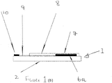
- FIG. 1(a) Shown in plan view in Figure 1(a) and in cross section in Figure 1(b) is a first embodiment of an electrochemical sensor of the invention 1 for the quantitative measurement of free chlorine and total chlorine in an aqueous sample.
- the electrochemical sensor 1 comprises a substrate in the form of a polymeric strip 2 on to which successive layers are deposited progressively by screen printing.
- a first successive layer is composed of four parallel spaced apart conductive tracks 9 of a highly conductive printable ink such as silver or silver/silver chloride. Each of the conductive tracks 9 terminates near to a first end 11 of the strip 2 in an electrical contact 10.
- a first of the four conductive tracks 9 constitutes a reference electrode 4.
- On a second of the four conductive tracks 9 near to a second end 12 of the strip 2 is deposited carbon to form a counter electrode 5.
- On a third and fourth of the four conductive tracks 9 near to the second end 12 of the strip 2 is deposited carbon to form a pair of working electrodes 6a, 6b.
- the working electrodes 6a, 6b flank the reference electrode 4 and the counter electrode 5.
- each electrode 4, 5, 6a, 6b is screen printed first and second layers of non-conductive ink 8.
- a screen used to deposit the first layer of non-conductive ink 8 is such that the electrical contacts 10 and the electrodes 4, 5, 6a, 6b are left exposed.
- a screen is used to deposit the second layer of non-conductive ink 8 on the carbon deposit of each working electrode 6a, 6b in such a way as to describe an array of apertures 7.
- Each aperture exposes a discrete working region of the working electrode 6a, 6b which thereby constitutes 95 discrete disc electrodes.
- the reference electrode 4 and the counter electrode 5 near to the second end 12 of the strip are left exposed.
- the dried reagent formulation includes tetramethylbenzidine (TMB), a phosphate buffer and polyvinylpyrrolidone.
- the dried reagent formulation includes potassium iodide (0.5g in 50ml), potassium hydrogen phthalate (1.02g in 50ml) and carboxymethylcellulose (0.125g in 50ml).
- Deposited onto the non-conductive ink 8 between the reference electrode 4 and the counter electrode 5 is a deposit 13 of sixteen doses of potassium chloride acting as a supporting electrolyte.
- the deposit 13 of doses is formed from a total volume of 3.2 ⁇ l of a 9.32g/100ml KCl solution dropped onto the non-conductive ink 8.
- the total mass of the deposit is 0.000298g.
- the electrochemical sensor 1 may be interfaced with a suitable portable field instrument (eg ChlordioXense, Palintest Ltd) to be operated amperometrically.
- a suitable portable field instrument eg ChlordioXense, Palintest Ltd
- Figure 1(c) Shown schematically in Figure 1(c) is a second embodiment of an electrochemical sensor of the invention 21 which is substantially identical to the first embodiment 1.
- the array of apertures constitutes multiple horizontal apertures (or microbands) 71.
- Figure 1(d) Shown schematically in Figure 1(d) is a third embodiment of an electrochemical sensor of the invention 31 which is substantially identical to the first embodiment 1.
- the array of apertures constitutes multiple vertical apertures (or microbands) 81.
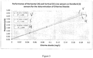
- a standard 350 micron electrochemical sensor of the type disclosed in WO-A-2007/026152 with circular apertures and examples of a sensor with horizontal and vertical microbands were prepared without a reagent formulation and used for the determination of chlorine dioxide in solution. In all cases, the sensors were dosed with KCl as described above. They showed similar performance in terms of signal response per area and limit of detection (LOD). The results are shown in Table 1 and Figure 3 .
- Table 1 Method Detection Limit (MDL) for sensors to determine Chlorine Dioxide Type MDL (ppb) Standard 3.6 Horizontal Line Sensor 4.6 Vertical Line Sensor 4.9
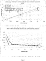
- a standard 350 micron electrochemical sensor of the type disclosed in WO-A-2007/026152 and examples of a sensor with horizontal and vertical microbands were prepared with a reagent formulation and used for the determination of chlorine in solution. In all cases, the sensors were dosed with KCl as described above. The sensors with horizontal and vertical microbands showed improved LOD performance relative to the standard sensor with circular apertures (see Table 2 and Figures 4A and 4B ).
- the deposit 13 of KCl acting as a supporting electrolyte deposited between the reference electrode 4 and the counter electrode 5 serves to inhibit the generation of plumes and ensure steady state readings.
- KCl does not take part in the electrochemical analysis.
- the dissolution of KCl into the bulk solution away from the first and second layer of non-conductive ink 8 reduces the difference in ionic strength between the boundary layer and bulk solution and limits the formation of convective plumes. This results in steady state currents and improves the capability of the electrochemical analysis.
Landscapes
- Health & Medical Sciences (AREA)
- Life Sciences & Earth Sciences (AREA)
- Chemical & Material Sciences (AREA)
- Pathology (AREA)
- General Physics & Mathematics (AREA)
- Immunology (AREA)
- Physics & Mathematics (AREA)
- Analytical Chemistry (AREA)
- Biochemistry (AREA)
- General Health & Medical Sciences (AREA)
- Molecular Biology (AREA)
- Chemical Kinetics & Catalysis (AREA)
- Electrochemistry (AREA)
- Food Science & Technology (AREA)
- Medicinal Chemistry (AREA)
- Engineering & Computer Science (AREA)
- Investigating Or Analyzing Materials By The Use Of Electric Means (AREA)
- Measuring Oxygen Concentration In Cells (AREA)
- Investigating Or Analyzing Non-Biological Materials By The Use Of Chemical Means (AREA)
Description
- The present invention relates to an electrochemical sensor for determining the presence or quantity (eg concentration) of an oxidant of interest in an aqueous solution.
- Electrochemical sensors of the type disclosed in
WO-A-2007/026152 have been developed with an overall area of working electrode which is small. These sensors are manufactured with working electrodes within the dimensional range (50-400 micron) for them to be considered to be microelectrodes. Microelectrodes have a number of advantages over macroelectrodes including faster mass transport rates, lower ohmic drop and improved diffusion provided that the gap between adjacent electrodes is sufficient to ensure diffusional independence (ie the proximity of the adjacent electrode does not limit the current at its nearest neighbours). - In these electrochemical sensors, a reagent formulation is dried on the electrode surface to provide the chemical components essential for specific ion electroanalysis. Once the electrochemical sensor is immersed in a test solution, dissolution takes place to give rise to natural convection of the reagent formulation from the surface into the bulk solution. The large difference in localised ionic strength between the boundary layer adjacent to the surface and the bulk solution gives rise to a convective plume emanating away from the surface. This introduces variability in the current measured over time and has a disruptive effect on chronoamperometric techniques.
-
WO-A-2007/026152 discloses that the small total current passed by a microelectrode makes it possible to operate in a solution without the addition of supporting electrolyte. This limits the number of operational steps required and is convenient for the user. It also prevents measurement errors which might otherwise be caused by the incorrect addition of a supporting electrolyte. - The present invention is based on the recognition that depositing a supporting electrolyte onto the surface of an electrochemical sensor away from the working electrode limits the formation of convective plumes of reagent and improves measurement capability.
- Thus viewed from a first aspect the present invention provides an electrochemical sensor for determining the presence or quantity of an oxidant of interest in an aqueous solution comprising:
- an elongate substrate layer having a first end opposite to a second end;
- first, second and third conductive tracks deposited axially onto the substrate layer in a parallel mutually spaced apart relationship, wherein the first conductive track constitutes a reference electrode, wherein on the second conductive track near to the second end of the substrate layer is a carbon deposit whereby to constitute a counter electrode and on the third conductive track near to the second end of the substrate layer is a carbon deposit whereby to constitute a working electrode, wherein each of the first, second and third conductive tracks terminates near to the first end of the substrate layer in an electrical contact;
- a non-conductive layer deposited on the first, second and third conductive tracks, wherein the non-conductive layer is fabricated to fully expose each electrical contact near to the first end of the substrate layer, to fully expose the carbon deposit on the second conductive track near to the second end of the substrate layer, to fully expose the first conductive track near to the second end of the substrate layer and to partially expose discrete working regions of the carbon deposit of the third conductive track through an array of apertures;
- a reagent formulation deposited on or near to the surface of the working electrode, wherein the reagent formulation includes a reductant; and
- a deposit of a supporting electrolyte deposited on the non-conductive layer.
- The reagent formulation provides the chemical components including the reductant essential for electroanalysis of a specific oxidant of interest.
- The first conductive track may be between the second conductive track and the third conductive track.
- Preferably the amount of the deposit of supporting electrolyte deposited on the non-conductive layer is sufficient in use to substantially remain within a boundary layer region at the surface of the non-conducting layer (eg over a measurement period such as a measurement period of about two minutes).
- Preferably the amount of the deposit of supporting electrolyte deposited on the non-conductive layer is in excess of 2.0 x 10⁻⁶ moles, particularly preferably in excess of 2.4 x 10⁻⁶ moles, more preferably in excess of 3.2 x 10⁻⁶ moles (eg about 4.0 x 10⁻⁶ moles).
- Preferably the amount of the deposit of supporting electrolyte deposited on the non-conductive layer is in the range 2.1 x 10⁻⁶ to 6.0 x 10⁻⁶ moles, particularly preferably in the range 2.4 x 10⁻⁶ to 5.6 x 10⁻⁶ moles, more preferably in the range 3.2 x 10⁻⁶ to 4.8 x 10⁻⁶ moles.
- Preferably the deposit of supporting electrolyte deposited on the non-conductive layer is depositable from an aqueous solution of the supporting electrolyte with a molarity in excess of 0.626 mol/l, particularly preferably in excess of 0.800 mol/l, more preferably in excess of 1.07 mol/l (eg about 1.25 mol/l).
- Preferably the deposit of supporting electrolyte deposited on the non-conductive layer is depositable from an aqueous solution of the supporting electrolyte with a molarity in the range 0.63 to 1.90 mol/l, particularly preferably 0.73 to 1.75 mol/l, more preferably in the range 1.00 to 1.50 mol/l.
- Typically the supporting electrolyte is inert (eg does not participate in the redox reaction).
- Preferably the supporting electrolyte is potassium chloride.
- The deposit of a supporting electrolyte may be deposited on a region of the non-conductive layer between (eg exclusively between) the fully exposed carbon deposit on the second conductive track and the partially exposed third conductive track.
In a preferred embodiment, the deposit of a supporting electrolyte is deposited on a region of the non-conductive layer between (eg exclusively between) the fully exposed carbon deposit on the second conductive track and the fully exposed first conductive track. - The deposit of a supporting electrolyte may be one or more doses of the supporting electrolyte deposited discretely on the non-conductive layer.
- Preferably the deposit of a supporting electrolyte is a plurality of doses of the supporting electrolyte deposited discretely on the non-conductive layer.
- The plurality of doses may be 10 to 20 doses (eg 16 doses). Typically the amount of the plurality of doses is 3 to 4µl (eg about 3.2µl).
- Preferably the plurality of doses is deposited in a parallel mutually spaced apart relationship to the first, second and third conductive track.
- The array of apertures may be fabricated in the non-conductive layer by a mechanical, chemical or physical removal technique such as ablation (eg photoablation) or etching. The array of apertures may be fabricated in the non-conductive layer by screen printing.
- Each aperture may have a substantially regular shape. Typically the apertures are uniformly shaped. Each aperture may be substantially circular or non-circular (eg rectangular or square).
- Preferably each aperture is substantially circular.
- The array may adopt any suitable pattern (eg cubic or rectangular). The array may comprise 10 to 500 apertures, preferably 50 to 200 apertures, more preferably 80 to 120, most preferably about 95 apertures.
- Preferably each aperture has a dimension (eg diameter) in the
range 50 to 400µm (eg about 350µm). - Each aperture may be elongate (eg linear). Each elongate aperture may be substantially parallel to the first, second and third conductive track (eg vertical).
- Preferably each elongate aperture is substantially perpendicular to the first, second and third conductive track (eg horizontal).
- In a preferred embodiment, each aperture of the array of apertures is substantially rectangular (eg a microband). For example, each aperture may be microscopic in width (eg about 50 microns) and macroscopic in length.
- In a preferred embodiment, the array of apertures is a substantially rectangular array.
- In a preferred embodiment, the electrochemical sensor further comprises:
a fourth conductive track deposited axially onto the substrate layer, wherein the first, second, third and fourth conductive track are in a parallel mutually spaced apart relationship, wherein on the fourth conductive track near to the second end of the substrate layer is a carbon deposit whereby the third and fourth conductive tracks constitute a pair of working electrodes, wherein the first and second conductive tracks are flanked by the third and fourth conductive tracks, wherein each of the first, second, third and fourth conductive tracks terminates near to the first end of the substrate layer in an electrical contact, wherein the non-conductive layer is deposited on the first, second, third and fourth conductive tracks and is fabricated to fully expose each electrical contact near to the first end of the substrate layer, to fully expose the carbon deposit on the second conductive track near to the second end of the substrate layer, to fully expose the first conductive track near to the second end of the substrate layer and to partially expose discrete working regions of the carbon deposits of the third and fourth conductive tracks through an array of apertures, wherein the reagent formulation is deposited on or near to the surface of either or both of the pair of working electrodes. - Preferably the plurality of doses is deposited in a parallel mutually spaced apart relationship to the first, second, third and fourth conductive track.
- The deposit of a supporting electrolyte may be deposited on a region of the non-conductive layer between (eg exclusively between) the fully exposed first conductive track and the partially exposed fourth conductive track.
- The deposit of a supporting electrolyte may be deposited on a region of the non-conductive layer which is not between any of the fully exposed carbon deposit on the second conductive track, the partially exposed third conductive track, the fully exposed first conductive track and the partially exposed fourth conductive track.
- Each aperture may be elongate (eg linear). Each elongate aperture may be substantially parallel to the first, second, third and fourth conductive track (eg vertical).
- Preferably each elongate aperture is substantially perpendicular to the first, second, third and fourth conductive track (eg horizontal).
- The pair of working electrodes may be a first working electrode connected to a first current amplifier and a second working electrode connected to a second current amplifier.
- The non-conductive layer may be fabricated by a known deposition or growth technique such as printing (eg screen printing, silk screen printing, ink-jet printing or thick film printing), casting, spinning, sputtering, lithography, vapour deposition, spray coating or vacuum deposition. Preferably the non-conductive layer is fabricated by screen printing. The non-conductive layer may be composed of a non-conductive ink.
- Each conductive track may be fabricated by a known deposition or growth technique such as printing (eg screen printing, silk screen printing or thick film printing), casting, spinning, sputtering, lithography, vapour deposition, spray coating or vacuum deposition. Each conductive track may be composed of an inert metal such as gold, silver or platinum. Each conductive track may be composed of a conductive ink such as silver or silver/silver chloride ink. The conductive ink may be printable.
- The substrate layer may be a sheet or strip. The substrate layer is typically composed of an insulating polymer. The substrate layer may be composed of polyester, polycarbonate or polyvinyl chloride.
- The carbon deposit on each conductive track may be deposited by known techniques such as printing (eg screen printing, silk screen printing, ink-jet printing or thick film printing), sputtering, lithography, vapour deposition, spray coating or vacuum deposition. The carbon deposit may be composed of inert carbon such as graphite, glassy carbon or pyrolytic carbon.
- Typically the electrochemical sensor is interfaced with an instrument (preferably a portable field instrument) in a system which facilitates the electrochemical sensor to be operated amperometrically.
- The electrochemical sensor may be integrated in an on-line system. Alternatively the electrochemical sensor may be portable. The electrochemical sensor may be single-use (eg disposable).
- The aqueous solution may be potable water, recreational water, process water or waste water (eg industrial waste water). Preferred is potable water.
- The sample of the aqueous solution may be brought into contact with the working electrode by dipping the working electrode into the sample of the aqueous solution or by dosing the sample of the aqueous solution onto the working electrode.
- Typically the quantity of the oxidant of interest is its concentration.
- Preferably the oxidant of interest is one or more of the group consisting of chlorine dioxide, chlorine, chlorite, hypochlorite, free chlorine, total chlorine, ozone, peracetic acid, hydrogen peroxide and monochloramine.
- Particularly preferably the oxidant of interest is free chlorine (and optionally total chlorine).
- The reductant may be an iodide such as an alkali metal iodide (eg potassium iodide), N, N-diethyl-p-phenyldiamine (DPD) or tetramethylbenzidine (TMB).
- The reagent formulation may further comprise one or more additives such as a buffer, gelling agent, thickening agent, wetting agent or stabiliser. Typical additives are one or more of the group consisting of sodium phosphate, potassium phthalate, sodium carbonate, disodium EDTA, hydroxylethylcellulose and polyvinylpyrrolidone. The reagent formulation may incorporate an acidic salt (eg sodium hydrogen sulphate) which in use reduces the pH to about 2.
- The reagent formulation may take the form of a reagent layer. A reagent layer advantageously permits the redox reaction between the oxidant of interest and the reductant to occur intimately in situ.
- The reagent formulation may be deposited and dried onto or near to the surface of either or both of the pair of working electrodes to form the reagent layer.
- The reagent layer may include a porous matrix. The reagent layer may include a porous matrix impregnated with the reductant. The porous matrix may comprise polyvinylpyrrolidone and/or hydroxyethylcellulose. The reductant may be impregnated in the porous matrix by printing or microdosing.
- In a preferred embodiment, the reagent formulation includes tetramethylbenzidine (TMB), a phosphate buffer and polyvinylpyrrolidone.
- The present invention will now be described in a non-limitative sense with reference to the accompanying Figures in which:
-
Figure 1 illustrates a first embodiment of an electrochemical sensor of the invention in (a) plan view and (b) cross sectional view; -
Figure 1(c) illustrates schematically a second embodiment of an electrochemical sensor of the invention; -
Figure 1(d) illustrates schematically a third embodiment of an electrochemical sensor of the invention; -
Figures 2A and 2B are current-time response curves for an electrochemical sensor with vertical microbands; -
Figure 3 illustrates the performance of sensors with standard circular (S), vertical (V) and horizontal (H) microbands for the determination of chlorine dioxide; -
Figure 4A illustrates the low range calibration for sensors with standard circular (S), vertical (V) and horizontal (H) microbands for the determination of chlorine; -
Figure 4B is the CV profile for sensors with standard circular (S), vertical (V) and horizontal (H) microbands for the determination of chlorine; -
Figure 5 are current-time response curves for (A) a standard electrochemical sensor and (B) an electrochemical sensor with vertical microbands; and -
Figure 6 is a current-time response curve for an electrochemical sensor with horizontal microbands. - Shown in plan view in
Figure 1(a) and in cross section inFigure 1(b) is a first embodiment of an electrochemical sensor of theinvention 1 for the quantitative measurement of free chlorine and total chlorine in an aqueous sample. Theelectrochemical sensor 1 comprises a substrate in the form of apolymeric strip 2 on to which successive layers are deposited progressively by screen printing. A first successive layer is composed of four parallel spaced apart conductive tracks 9 of a highly conductive printable ink such as silver or silver/silver chloride. Each of the conductive tracks 9 terminates near to a first end 11 of thestrip 2 in anelectrical contact 10. - A first of the four conductive tracks 9 constitutes a
reference electrode 4. On a second of the four conductive tracks 9 near to asecond end 12 of thestrip 2 is deposited carbon to form acounter electrode 5. On a third and fourth of the four conductive tracks 9 near to thesecond end 12 of thestrip 2 is deposited carbon to form a pair of working electrodes 6a, 6b. The working electrodes 6a, 6b flank thereference electrode 4 and thecounter electrode 5. - Over the top of each
electrode non-conductive ink 8. During screen printing, a screen used to deposit the first layer ofnon-conductive ink 8 is such that theelectrical contacts 10 and theelectrodes non-conductive ink 8 on the carbon deposit of each working electrode 6a, 6b in such a way as to describe an array ofapertures 7. Each aperture exposes a discrete working region of the working electrode 6a, 6b which thereby constitutes 95 discrete disc electrodes. Thereference electrode 4 and thecounter electrode 5 near to thesecond end 12 of the strip are left exposed. - On the working electrode 6b is deposited a dried reagent formulation which provides the chemical components essential for the direct determination of free chlorine. The dried reagent formulation includes tetramethylbenzidine (TMB), a phosphate buffer and polyvinylpyrrolidone.
- On the working electrode 6a is deposited a dried reagent formulation which provides the chemical components essential for the direct determination of total chlorine. The dried reagent formulation includes potassium iodide (0.5g in 50ml), potassium hydrogen phthalate (1.02g in 50ml) and carboxymethylcellulose (0.125g in 50ml).
- Deposited onto the
non-conductive ink 8 between thereference electrode 4 and thecounter electrode 5 is adeposit 13 of sixteen doses of potassium chloride acting as a supporting electrolyte. Thedeposit 13 of doses is formed from a total volume of 3.2µl of a 9.32g/100ml KCl solution dropped onto thenon-conductive ink 8. The total mass of the deposit is 0.000298g. - The
electrochemical sensor 1 may be interfaced with a suitable portable field instrument (eg ChlordioXense, Palintest Ltd) to be operated amperometrically. - Shown schematically in
Figure 1(c) is a second embodiment of an electrochemical sensor of theinvention 21 which is substantially identical to thefirst embodiment 1. However in the case of thesecond embodiment 21, the array of apertures constitutes multiple horizontal apertures (or microbands) 71. - Shown schematically in
Figure 1(d) is a third embodiment of an electrochemical sensor of theinvention 31 which is substantially identical to thefirst embodiment 1. However in the case of thethird embodiment 31, the array of apertures constitutes multiple vertical apertures (or microbands) 81. - When a 200 micron vertical microband electrochemical sensor of the type shown in
Figure 1(d) but withoutKCl deposit 13 is dosed with a dried reagent formulation and immersed in a test aqueous solution, the large difference in localised ionic strength between the boundary layer adjacent to the surface and the bulk solution gives rise to a convective plume emanating away from the surface. The effect of this plume on the current is demonstrated inFigure 2B . It can be seen that the current-time response varies significantly for low chlorine test solutions (0.1mg/L inFigure 2B ) and high chlorine test solutions (0.5mg/L inFigure 2B ) and that there are inconsistent readings for multiple analyses of the same solution. - If the same experiment is carried out with no reagent formulation dosed onto the vertical microband electrochemical sensor and the equivalent concentration of reagents added to the bulk solution, no disruption of the steady state current is observed (see
Figure 2A ). The conclusion is that the perturbation of the current response is a direct consequence of the presence of the reagent formulation at the surface of the working electrode. - A standard 350 micron electrochemical sensor of the type disclosed in
WO-A-2007/026152 with circular apertures and examples of a sensor with horizontal and vertical microbands were prepared without a reagent formulation and used for the determination of chlorine dioxide in solution. In all cases, the sensors were dosed with KCl as described above. They showed similar performance in terms of signal response per area and limit of detection (LOD). The results are shown in Table 1 andFigure 3 .Table 1: Method Detection Limit (MDL) for sensors to determine Chlorine Dioxide Type MDL (ppb) Standard 3.6 Horizontal Line Sensor 4.6 Vertical Line Sensor 4.9 - A standard 350 micron electrochemical sensor of the type disclosed in
WO-A-2007/026152 and examples of a sensor with horizontal and vertical microbands were prepared with a reagent formulation and used for the determination of chlorine in solution. In all cases, the sensors were dosed with KCl as described above. The sensors with horizontal and vertical microbands showed improved LOD performance relative to the standard sensor with circular apertures (see Table 2 andFigures 4A and 4B ).Table 2 Free Chlorine Horizontal lines [Chlorine]/mg/L av_a/d free sd CV LOD (ppb) 0 0.00 0.005 387% 16 (1) 0.01 0.14 0.02 16% 0.0504 0.91 0.05 5.2% 6(2) 0.1007 1.95 0.12 6.1% 0.5 12.36 0.44 3.5% [Chlorine]/mg/L Vertical lines av_a/d free sd CV LOD (ppb) 0 0.01 0.017 149% 19 (1) 0.01 0.14 0.03 19% 0.0504 0.76 0.04 5.1% 6 (2) 0.1007 1.62 0.11 6.9% 0.5 9.82 0.49 5.0% Standard [Chlorine]/mg/L av_a/d free sd CV LOD (ppb) 0 0.04 0.062 172% 37 (1) 0.01 0.11 0.1 44.8% 0.0504 0.89 0.1 15.7% 20 (2) 0.1007 1.90 0.3 13.2% 0.5 11.84 0.4 3.7% - During the determination of chlorine, a number of test results showed a deviation from the normal current-time response curve (see
Figures 5A and 5B ). These atypical responses for standard sensors and for sensors with vertical microbands are due to convection plumes arising from the presence of the reagent formulation at the electrode surface. It was evident that the size and severity of the plume was related to the vertical dimension of the electrode surface such that the circular electrodes of the standard sensor demonstrated less current variability than the vertical microband electrodes. This is explained by the dissolution of the reagent cascading down the surface disrupting the electrode boundary layer. Plumes were not observed on sensors with 150 micron horizontal microbands (seeFigure 6 ). - Studies on the
electrochemical sensor 1 of the invention described above have shown that thedeposit 13 of KCl acting as a supporting electrolyte deposited between thereference electrode 4 and thecounter electrode 5 serves to inhibit the generation of plumes and ensure steady state readings. KCl does not take part in the electrochemical analysis. The dissolution of KCl into the bulk solution away from the first and second layer ofnon-conductive ink 8 reduces the difference in ionic strength between the boundary layer and bulk solution and limits the formation of convective plumes. This results in steady state currents and improves the capability of the electrochemical analysis.
Claims (12)
- An electrochemical sensor (1) for determining the presence or quantity of an oxidant of interest in an aqueous solution comprising:an elongate substrate layer (2) having a first end (11) opposite to a second end (12);first, second and third conductive tracks (9) deposited axially onto the substrate layer (2) in a parallel mutually spaced apart relationship, wherein the first conductive track constitutes a reference electrode (4), wherein on the second conductive track near to the second end (12) of the substrate layer (2) is a carbon deposit whereby to constitute a counter electrode (5) and on the third conductive track near to the second end (12) of the substrate layer (2) is a carbon deposit whereby to constitute a working electrode (6b), wherein each of the first, second and third conductive tracks (9) terminates near to the first end (11) of the substrate layer (2) in an electrical contact (10);a non-conductive layer (8) deposited on the first, second and third conductive tracks (9), wherein the non-conductive layer (8) is fabricated to fully expose each electrical contact (10) near to the first end (11) of the substrate layer (2), to fully expose the carbon deposit on the second conductive track near to the second end (12) of the substrate layer (2), to fully expose the first conductive track near to the second end (12) of the substrate layer (2) and to partially expose discrete working regions of the carbon deposit of the third conductive track through an array of apertures (7);a reagent formulation deposited on or near to the surface of the working electrode (6b), wherein the reagent formulation includes a reductant; anda deposit (13) of a supporting electrolyte deposited on the non-conductive layer (8).
- An electrochemical sensor (1) as claimed in claim 1 wherein the amount of the deposit (13) of supporting electrolyte deposited on the non-conductive layer (8) is in excess of 2.0 x 10⁻⁶ moles.
- An electrochemical sensor (1) as claimed in any preceding claim wherein the amount of the deposit (13) of supporting electrolyte deposited on the non-conductive layer (8) is in the range 2.1 x 10⁻⁶ to 6.0 x 10⁻⁶ moles.
- An electrochemical sensor (1) as claimed in any preceding claim wherein the supporting electrolyte is potassium chloride.
- An electrochemical sensor (1) as claimed in any preceding claim wherein the deposit (13) of a supporting electrolyte is deposited on a region of the non-conductive layer (8) between the fully exposed carbon deposit on the second conductive track and the fully exposed first conductive track.
- An electrochemical sensor (1) as claimed in any preceding claim wherein the deposit (13) of a supporting electrolyte is a plurality of doses of the supporting electrolyte deposited discretely on the non-conductive layer (8).
- An electrochemical sensor (1) as claimed in any preceding claim wherein each aperture is elongate and substantially perpendicular to the first, second and third conductive tracks (9).
- An electrochemical sensor (1) as claimed in any preceding claim further comprising:
a fourth conductive track deposited axially onto the substrate layer (2), wherein the first, second, third and fourth conductive tracks (9) are in a parallel mutually spaced apart relationship, wherein on the fourth conductive track near to the second end (12) of the substrate layer (2) is a carbon deposit whereby the third and fourth conductive tracks constitute a pair of working electrodes (6a, 6b), wherein the first and second conductive tracks are flanked by the third and fourth conductive tracks, wherein each of the first, second, third and fourth conductive tracks (9) terminates near to the first end (11) of the substrate layer (2) in an electrical contact (10), wherein the non-conductive layer (8) is deposited on the first, second, third and fourth conductive tracks (9) and is fabricated to fully expose each electrical contact (10) near to the first end (11) of the substrate layer (2), to fully expose the carbon deposit on the second conductive track near to the second end (12) of the substrate layer (2), to fully expose the first conductive track near to the second end (12) of the substrate layer (2) and to partially expose discrete working regions of the carbon deposits of the third and fourth conductive tracks through an array of apertures (7), wherein the reagent formulation is deposited on or near to the surface of either or both of the pair of working electrodes (6a, 6b). - An electrochemical sensor (1) as claimed in claim 8 wherein the plurality of doses is deposited in a parallel mutually spaced apart relationship to the first, second, third and fourth conductive tracks (9).
- An electrochemical sensor (1) as claimed in claim 8 or 9 wherein each aperture is elongate and substantially perpendicular to the first, second, third and fourth conductive tracks (9).
- An electrochemical sensor (1) as claimed in any preceding claim wherein each aperture of the array of apertures (7) is substantially rectangular.
- An electrochemical sensor (1) as claimed in any preceding claim wherein the oxidant of interest is one or more of the group consisting of chlorine dioxide, chlorine, chlorite, hypochlorite, free chlorine, total chlorine, ozone, peracetic acid, hydrogen peroxide and monochloramine.
Applications Claiming Priority (2)
| Application Number | Priority Date | Filing Date | Title |
|---|---|---|---|
| GB1606111.1A GB2549281A (en) | 2016-04-11 | 2016-04-11 | Electrochemical sensor |
| PCT/GB2017/050818 WO2017178784A1 (en) | 2016-04-11 | 2017-03-23 | Electrochemical sensor |
Publications (2)
| Publication Number | Publication Date |
|---|---|
| EP3443336A1 EP3443336A1 (en) | 2019-02-20 |
| EP3443336B1 true EP3443336B1 (en) | 2020-08-26 |
Family
ID=58464595
Family Applications (1)
| Application Number | Title | Priority Date | Filing Date |
|---|---|---|---|
| EP17715261.8A Active EP3443336B1 (en) | 2016-04-11 | 2017-03-23 | Electrochemical sensor |
Country Status (6)
| Country | Link |
|---|---|
| US (1) | US10895549B2 (en) |
| EP (1) | EP3443336B1 (en) |
| CN (1) | CN109154582B (en) |
| AU (1) | AU2017251591B2 (en) |
| GB (1) | GB2549281A (en) |
| WO (1) | WO2017178784A1 (en) |
Families Citing this family (2)
| Publication number | Priority date | Publication date | Assignee | Title |
|---|---|---|---|---|
| GB2567681B (en) * | 2017-10-20 | 2022-05-04 | Palintest Ltd | Amperometric instrument for an electrochemical sensor |
| GB2599115B (en) * | 2020-09-24 | 2025-03-05 | Palintest Ltd | Electrochemical sensor |
Family Cites Families (9)
| Publication number | Priority date | Publication date | Assignee | Title |
|---|---|---|---|---|
| US6241862B1 (en) * | 1996-02-14 | 2001-06-05 | Inverness Medical Technology, Inc. | Disposable test strips with integrated reagent/blood separation layer |
| JP2001004581A (en) * | 1999-06-24 | 2001-01-12 | Sentan Kagaku Gijutsu Incubation Center:Kk | Micro reference electrode |
| CN1432130A (en) * | 2000-03-08 | 2003-07-23 | 糖尿病诊断公司 | Rapid response glucose sensor |
| CN101533007B (en) * | 2003-10-31 | 2013-01-02 | 生命扫描苏格兰有限公司 | Method of reducing the effect of direct interference current in an electrochemical test strip |
| GB0517773D0 (en) | 2005-09-01 | 2005-10-12 | Palintest Ltd | Electrochemical sensor |
| GB0820817D0 (en) * | 2008-11-13 | 2008-12-24 | Wireless Biodevices Ltd | Electrode, electrochemical sensor and apparatus, and methods for operating the same |
| CN102471796A (en) * | 2009-07-27 | 2012-05-23 | 舒尔传感器有限公司 | Improvements relating to sensor devices |
| GB201012148D0 (en) * | 2010-07-20 | 2010-09-01 | Palintest Ltd | Method |
| CN102628827A (en) * | 2012-04-10 | 2012-08-08 | 凯晶生物科技(苏州)有限公司 | DNA (Deoxyribonucleic Acid) electrochemical sensor based on MOSFET (Metal-Oxide -Semiconductor Field Effect Transistor) structure and manufacturing method thereof |
-
2016
- 2016-04-11 GB GB1606111.1A patent/GB2549281A/en not_active Withdrawn
-
2017
- 2017-03-23 WO PCT/GB2017/050818 patent/WO2017178784A1/en not_active Ceased
- 2017-03-23 EP EP17715261.8A patent/EP3443336B1/en active Active
- 2017-03-23 CN CN201780022896.5A patent/CN109154582B/en active Active
- 2017-03-23 AU AU2017251591A patent/AU2017251591B2/en active Active
- 2017-03-27 US US16/082,569 patent/US10895549B2/en active Active
Non-Patent Citations (1)
| Title |
|---|
| None * |
Also Published As
| Publication number | Publication date |
|---|---|
| AU2017251591B2 (en) | 2021-05-27 |
| CN109154582A (en) | 2019-01-04 |
| WO2017178784A1 (en) | 2017-10-19 |
| US10895549B2 (en) | 2021-01-19 |
| US20190033246A1 (en) | 2019-01-31 |
| CN109154582B (en) | 2021-07-20 |
| GB2549281A (en) | 2017-10-18 |
| EP3443336A1 (en) | 2019-02-20 |
| AU2017251591A1 (en) | 2018-07-26 |
Similar Documents
| Publication | Publication Date | Title |
|---|---|---|
| US9696273B2 (en) | Reference half-cell and electrochemical sensor with the reference half-cell | |
| Kurzweil | Metal oxides and ion-exchanging surfaces as pH sensors in liquids: State-of-the-art and outlook | |
| US11307163B2 (en) | Carbon nanotube based reference electrodes and all-carbon electrode assemblies for sensing and electrochemical characterization | |
| JP7455582B2 (en) | Nano- and/or micro-structured printed electrodes | |
| US10895549B2 (en) | Electrochemical sensor | |
| US20190004000A1 (en) | Sensor for analytes | |
| US20190004006A1 (en) | Potentiostat circuit | |
| WO2012010864A1 (en) | Method and device for determining an oxydant in an aqueous solution | |
| JP3194090B2 (en) | Electrochemical sensor | |
| EP4217720B1 (en) | Electrochemical sensor | |
| EP3698128B1 (en) | Electroanalytical instrument for determining by amperometry the presence or quantity of an analyte in an aqueous sample | |
| Junlapak et al. | A Flow Injection Amperometric Sensor for Nitrate Detection Based on Cu Foam/Ordered Mesoporous Carbon Modified Glassy Carbon Electrode | |
| DE102016005943A1 (en) | Process for the preparation of glass-based chemosensors | |
| Salem et al. | Selective determination of dopamine by novel electrochemical sensors based on nickel nano particles | |
| RU2059237C1 (en) | Carbonate-selective electrode with internal solid contact | |
| CN105556299A (en) | Electrochemical-based analytical test strip with ultra-thin discontinuous metal layer | |
| DE102013019636A1 (en) | Electrochemical sensor element | |
| US20040216999A1 (en) | Ion selective monoelectrode complex | |
| DE102008005065A1 (en) | Reference electrode for electro-chemical measurements by sensor chip, is made of biocompatible material e.g. precious metal or precious metal alloy, where electrode is formed on substrate, and is planar | |
| Vetik et al. | The application of RuO2-based pH-sensors in common beverages | |
| JPH0894572A (en) | Anode and device for measuring hypochlorite concentration |
Legal Events
| Date | Code | Title | Description |
|---|---|---|---|
| STAA | Information on the status of an ep patent application or granted ep patent |
Free format text: STATUS: UNKNOWN |
|
| STAA | Information on the status of an ep patent application or granted ep patent |
Free format text: STATUS: THE INTERNATIONAL PUBLICATION HAS BEEN MADE |
|
| PUAI | Public reference made under article 153(3) epc to a published international application that has entered the european phase |
Free format text: ORIGINAL CODE: 0009012 |
|
| STAA | Information on the status of an ep patent application or granted ep patent |
Free format text: STATUS: REQUEST FOR EXAMINATION WAS MADE |
|
| 17P | Request for examination filed |
Effective date: 20180613 |
|
| AK | Designated contracting states |
Kind code of ref document: A1 Designated state(s): AL AT BE BG CH CY CZ DE DK EE ES FI FR GB GR HR HU IE IS IT LI LT LU LV MC MK MT NL NO PL PT RO RS SE SI SK SM TR |
|
| AX | Request for extension of the european patent |
Extension state: BA ME |
|
| DAV | Request for validation of the european patent (deleted) | ||
| DAX | Request for extension of the european patent (deleted) | ||
| GRAP | Despatch of communication of intention to grant a patent |
Free format text: ORIGINAL CODE: EPIDOSNIGR1 |
|
| STAA | Information on the status of an ep patent application or granted ep patent |
Free format text: STATUS: GRANT OF PATENT IS INTENDED |
|
| INTG | Intention to grant announced |
Effective date: 20200326 |
|
| GRAS | Grant fee paid |
Free format text: ORIGINAL CODE: EPIDOSNIGR3 |
|
| GRAA | (expected) grant |
Free format text: ORIGINAL CODE: 0009210 |
|
| STAA | Information on the status of an ep patent application or granted ep patent |
Free format text: STATUS: THE PATENT HAS BEEN GRANTED |
|
| AK | Designated contracting states |
Kind code of ref document: B1 Designated state(s): AL AT BE BG CH CY CZ DE DK EE ES FI FR GB GR HR HU IE IS IT LI LT LU LV MC MK MT NL NO PL PT RO RS SE SI SK SM TR |
|
| REG | Reference to a national code |
Ref country code: GB Ref legal event code: FG4D |
|
| REG | Reference to a national code |
Ref country code: CH Ref legal event code: EP |
|
| REG | Reference to a national code |
Ref country code: AT Ref legal event code: REF Ref document number: 1306848 Country of ref document: AT Kind code of ref document: T Effective date: 20200915 |
|
| REG | Reference to a national code |
Ref country code: IE Ref legal event code: FG4D |
|
| REG | Reference to a national code |
Ref country code: DE Ref legal event code: R096 Ref document number: 602017022335 Country of ref document: DE |
|
| REG | Reference to a national code |
Ref country code: LT Ref legal event code: MG4D |
|
| PG25 | Lapsed in a contracting state [announced via postgrant information from national office to epo] |
Ref country code: FI Free format text: LAPSE BECAUSE OF FAILURE TO SUBMIT A TRANSLATION OF THE DESCRIPTION OR TO PAY THE FEE WITHIN THE PRESCRIBED TIME-LIMIT Effective date: 20200826 Ref country code: PT Free format text: LAPSE BECAUSE OF FAILURE TO SUBMIT A TRANSLATION OF THE DESCRIPTION OR TO PAY THE FEE WITHIN THE PRESCRIBED TIME-LIMIT Effective date: 20201228 Ref country code: HR Free format text: LAPSE BECAUSE OF FAILURE TO SUBMIT A TRANSLATION OF THE DESCRIPTION OR TO PAY THE FEE WITHIN THE PRESCRIBED TIME-LIMIT Effective date: 20200826 Ref country code: BG Free format text: LAPSE BECAUSE OF FAILURE TO SUBMIT A TRANSLATION OF THE DESCRIPTION OR TO PAY THE FEE WITHIN THE PRESCRIBED TIME-LIMIT Effective date: 20201126 Ref country code: SE Free format text: LAPSE BECAUSE OF FAILURE TO SUBMIT A TRANSLATION OF THE DESCRIPTION OR TO PAY THE FEE WITHIN THE PRESCRIBED TIME-LIMIT Effective date: 20200826 Ref country code: LT Free format text: LAPSE BECAUSE OF FAILURE TO SUBMIT A TRANSLATION OF THE DESCRIPTION OR TO PAY THE FEE WITHIN THE PRESCRIBED TIME-LIMIT Effective date: 20200826 Ref country code: GR Free format text: LAPSE BECAUSE OF FAILURE TO SUBMIT A TRANSLATION OF THE DESCRIPTION OR TO PAY THE FEE WITHIN THE PRESCRIBED TIME-LIMIT Effective date: 20201127 Ref country code: NO Free format text: LAPSE BECAUSE OF FAILURE TO SUBMIT A TRANSLATION OF THE DESCRIPTION OR TO PAY THE FEE WITHIN THE PRESCRIBED TIME-LIMIT Effective date: 20201126 |
|
| REG | Reference to a national code |
Ref country code: NL Ref legal event code: MP Effective date: 20200826 |
|
| REG | Reference to a national code |
Ref country code: AT Ref legal event code: MK05 Ref document number: 1306848 Country of ref document: AT Kind code of ref document: T Effective date: 20200826 |
|
| PG25 | Lapsed in a contracting state [announced via postgrant information from national office to epo] |
Ref country code: NL Free format text: LAPSE BECAUSE OF FAILURE TO SUBMIT A TRANSLATION OF THE DESCRIPTION OR TO PAY THE FEE WITHIN THE PRESCRIBED TIME-LIMIT Effective date: 20200826 Ref country code: RS Free format text: LAPSE BECAUSE OF FAILURE TO SUBMIT A TRANSLATION OF THE DESCRIPTION OR TO PAY THE FEE WITHIN THE PRESCRIBED TIME-LIMIT Effective date: 20200826 Ref country code: PL Free format text: LAPSE BECAUSE OF FAILURE TO SUBMIT A TRANSLATION OF THE DESCRIPTION OR TO PAY THE FEE WITHIN THE PRESCRIBED TIME-LIMIT Effective date: 20200826 Ref country code: LV Free format text: LAPSE BECAUSE OF FAILURE TO SUBMIT A TRANSLATION OF THE DESCRIPTION OR TO PAY THE FEE WITHIN THE PRESCRIBED TIME-LIMIT Effective date: 20200826 Ref country code: IS Free format text: LAPSE BECAUSE OF FAILURE TO SUBMIT A TRANSLATION OF THE DESCRIPTION OR TO PAY THE FEE WITHIN THE PRESCRIBED TIME-LIMIT Effective date: 20201226 |
|
| PG25 | Lapsed in a contracting state [announced via postgrant information from national office to epo] |
Ref country code: CZ Free format text: LAPSE BECAUSE OF FAILURE TO SUBMIT A TRANSLATION OF THE DESCRIPTION OR TO PAY THE FEE WITHIN THE PRESCRIBED TIME-LIMIT Effective date: 20200826 Ref country code: DK Free format text: LAPSE BECAUSE OF FAILURE TO SUBMIT A TRANSLATION OF THE DESCRIPTION OR TO PAY THE FEE WITHIN THE PRESCRIBED TIME-LIMIT Effective date: 20200826 Ref country code: RO Free format text: LAPSE BECAUSE OF FAILURE TO SUBMIT A TRANSLATION OF THE DESCRIPTION OR TO PAY THE FEE WITHIN THE PRESCRIBED TIME-LIMIT Effective date: 20200826 Ref country code: EE Free format text: LAPSE BECAUSE OF FAILURE TO SUBMIT A TRANSLATION OF THE DESCRIPTION OR TO PAY THE FEE WITHIN THE PRESCRIBED TIME-LIMIT Effective date: 20200826 Ref country code: SM Free format text: LAPSE BECAUSE OF FAILURE TO SUBMIT A TRANSLATION OF THE DESCRIPTION OR TO PAY THE FEE WITHIN THE PRESCRIBED TIME-LIMIT Effective date: 20200826 |
|
| REG | Reference to a national code |
Ref country code: DE Ref legal event code: R097 Ref document number: 602017022335 Country of ref document: DE |
|
| PG25 | Lapsed in a contracting state [announced via postgrant information from national office to epo] |
Ref country code: AT Free format text: LAPSE BECAUSE OF FAILURE TO SUBMIT A TRANSLATION OF THE DESCRIPTION OR TO PAY THE FEE WITHIN THE PRESCRIBED TIME-LIMIT Effective date: 20200826 Ref country code: AL Free format text: LAPSE BECAUSE OF FAILURE TO SUBMIT A TRANSLATION OF THE DESCRIPTION OR TO PAY THE FEE WITHIN THE PRESCRIBED TIME-LIMIT Effective date: 20200826 Ref country code: ES Free format text: LAPSE BECAUSE OF FAILURE TO SUBMIT A TRANSLATION OF THE DESCRIPTION OR TO PAY THE FEE WITHIN THE PRESCRIBED TIME-LIMIT Effective date: 20200826 |
|
| PG25 | Lapsed in a contracting state [announced via postgrant information from national office to epo] |
Ref country code: SK Free format text: LAPSE BECAUSE OF FAILURE TO SUBMIT A TRANSLATION OF THE DESCRIPTION OR TO PAY THE FEE WITHIN THE PRESCRIBED TIME-LIMIT Effective date: 20200826 |
|
| PLBE | No opposition filed within time limit |
Free format text: ORIGINAL CODE: 0009261 |
|
| STAA | Information on the status of an ep patent application or granted ep patent |
Free format text: STATUS: NO OPPOSITION FILED WITHIN TIME LIMIT |
|
| PG25 | Lapsed in a contracting state [announced via postgrant information from national office to epo] |
Ref country code: IT Free format text: LAPSE BECAUSE OF FAILURE TO SUBMIT A TRANSLATION OF THE DESCRIPTION OR TO PAY THE FEE WITHIN THE PRESCRIBED TIME-LIMIT Effective date: 20200826 |
|
| 26N | No opposition filed |
Effective date: 20210527 |
|
| PG25 | Lapsed in a contracting state [announced via postgrant information from national office to epo] |
Ref country code: SI Free format text: LAPSE BECAUSE OF FAILURE TO SUBMIT A TRANSLATION OF THE DESCRIPTION OR TO PAY THE FEE WITHIN THE PRESCRIBED TIME-LIMIT Effective date: 20200826 |
|
| PG25 | Lapsed in a contracting state [announced via postgrant information from national office to epo] |
Ref country code: MC Free format text: LAPSE BECAUSE OF FAILURE TO SUBMIT A TRANSLATION OF THE DESCRIPTION OR TO PAY THE FEE WITHIN THE PRESCRIBED TIME-LIMIT Effective date: 20200826 |
|
| REG | Reference to a national code |
Ref country code: CH Ref legal event code: PL |
|
| REG | Reference to a national code |
Ref country code: BE Ref legal event code: MM Effective date: 20210331 |
|
| PG25 | Lapsed in a contracting state [announced via postgrant information from national office to epo] |
Ref country code: IE Free format text: LAPSE BECAUSE OF NON-PAYMENT OF DUE FEES Effective date: 20210323 Ref country code: LU Free format text: LAPSE BECAUSE OF NON-PAYMENT OF DUE FEES Effective date: 20210323 Ref country code: LI Free format text: LAPSE BECAUSE OF NON-PAYMENT OF DUE FEES Effective date: 20210331 Ref country code: CH Free format text: LAPSE BECAUSE OF NON-PAYMENT OF DUE FEES Effective date: 20210331 |
|
| PG25 | Lapsed in a contracting state [announced via postgrant information from national office to epo] |
Ref country code: BE Free format text: LAPSE BECAUSE OF NON-PAYMENT OF DUE FEES Effective date: 20210331 |
|
| PG25 | Lapsed in a contracting state [announced via postgrant information from national office to epo] |
Ref country code: CY Free format text: LAPSE BECAUSE OF FAILURE TO SUBMIT A TRANSLATION OF THE DESCRIPTION OR TO PAY THE FEE WITHIN THE PRESCRIBED TIME-LIMIT Effective date: 20200826 |
|
| PG25 | Lapsed in a contracting state [announced via postgrant information from national office to epo] |
Ref country code: HU Free format text: LAPSE BECAUSE OF FAILURE TO SUBMIT A TRANSLATION OF THE DESCRIPTION OR TO PAY THE FEE WITHIN THE PRESCRIBED TIME-LIMIT; INVALID AB INITIO Effective date: 20170323 |
|
| PG25 | Lapsed in a contracting state [announced via postgrant information from national office to epo] |
Ref country code: MK Free format text: LAPSE BECAUSE OF FAILURE TO SUBMIT A TRANSLATION OF THE DESCRIPTION OR TO PAY THE FEE WITHIN THE PRESCRIBED TIME-LIMIT Effective date: 20200826 |
|
| PG25 | Lapsed in a contracting state [announced via postgrant information from national office to epo] |
Ref country code: MT Free format text: LAPSE BECAUSE OF FAILURE TO SUBMIT A TRANSLATION OF THE DESCRIPTION OR TO PAY THE FEE WITHIN THE PRESCRIBED TIME-LIMIT Effective date: 20200826 |
|
| PGFP | Annual fee paid to national office [announced via postgrant information from national office to epo] |
Ref country code: DE Payment date: 20250331 Year of fee payment: 9 |
|
| PG25 | Lapsed in a contracting state [announced via postgrant information from national office to epo] |
Ref country code: TR Free format text: LAPSE BECAUSE OF FAILURE TO SUBMIT A TRANSLATION OF THE DESCRIPTION OR TO PAY THE FEE WITHIN THE PRESCRIBED TIME-LIMIT Effective date: 20200826 |
|
| PGFP | Annual fee paid to national office [announced via postgrant information from national office to epo] |
Ref country code: GB Payment date: 20260330 Year of fee payment: 10 |
|
| PGFP | Annual fee paid to national office [announced via postgrant information from national office to epo] |
Ref country code: FR Payment date: 20260327 Year of fee payment: 10 |