EP3443226B1 - Controller for compressor - Google Patents
Controller for compressor Download PDFInfo
- Publication number
- EP3443226B1 EP3443226B1 EP17719344.8A EP17719344A EP3443226B1 EP 3443226 B1 EP3443226 B1 EP 3443226B1 EP 17719344 A EP17719344 A EP 17719344A EP 3443226 B1 EP3443226 B1 EP 3443226B1
- Authority
- EP
- European Patent Office
- Prior art keywords
- controller
- compressor
- motor
- vsd
- vsd motor
- Prior art date
- Legal status (The legal status is an assumption and is not a legal conclusion. Google has not performed a legal analysis and makes no representation as to the accuracy of the status listed.)
- Active
Links
Images

Classifications
-
- F—MECHANICAL ENGINEERING; LIGHTING; HEATING; WEAPONS; BLASTING
- F04—POSITIVE - DISPLACEMENT MACHINES FOR LIQUIDS; PUMPS FOR LIQUIDS OR ELASTIC FLUIDS
- F04C—ROTARY-PISTON, OR OSCILLATING-PISTON, POSITIVE-DISPLACEMENT MACHINES FOR LIQUIDS; ROTARY-PISTON, OR OSCILLATING-PISTON, POSITIVE-DISPLACEMENT PUMPS
- F04C23/00—Combinations of two or more pumps, each being of rotary-piston or oscillating-piston type, specially adapted for elastic fluids; Pumping installations specially adapted for elastic fluids; Multi-stage pumps specially adapted for elastic fluids
-
- F—MECHANICAL ENGINEERING; LIGHTING; HEATING; WEAPONS; BLASTING
- F25—REFRIGERATION OR COOLING; COMBINED HEATING AND REFRIGERATION SYSTEMS; HEAT PUMP SYSTEMS; MANUFACTURE OR STORAGE OF ICE; LIQUEFACTION SOLIDIFICATION OF GASES
- F25B—REFRIGERATION MACHINES, PLANTS OR SYSTEMS; COMBINED HEATING AND REFRIGERATION SYSTEMS; HEAT PUMP SYSTEMS
- F25B49/00—Arrangement or mounting of control or safety devices
- F25B49/02—Arrangement or mounting of control or safety devices for compression type machines, plants or systems
- F25B49/025—Motor control arrangements
-
- F—MECHANICAL ENGINEERING; LIGHTING; HEATING; WEAPONS; BLASTING
- F04—POSITIVE - DISPLACEMENT MACHINES FOR LIQUIDS; PUMPS FOR LIQUIDS OR ELASTIC FLUIDS
- F04C—ROTARY-PISTON, OR OSCILLATING-PISTON, POSITIVE-DISPLACEMENT MACHINES FOR LIQUIDS; ROTARY-PISTON, OR OSCILLATING-PISTON, POSITIVE-DISPLACEMENT PUMPS
- F04C23/00—Combinations of two or more pumps, each being of rotary-piston or oscillating-piston type, specially adapted for elastic fluids; Pumping installations specially adapted for elastic fluids; Multi-stage pumps specially adapted for elastic fluids
- F04C23/001—Combinations of two or more pumps, each being of rotary-piston or oscillating-piston type, specially adapted for elastic fluids; Pumping installations specially adapted for elastic fluids; Multi-stage pumps specially adapted for elastic fluids of similar working principle
-
- F—MECHANICAL ENGINEERING; LIGHTING; HEATING; WEAPONS; BLASTING
- F04—POSITIVE - DISPLACEMENT MACHINES FOR LIQUIDS; PUMPS FOR LIQUIDS OR ELASTIC FLUIDS
- F04C—ROTARY-PISTON, OR OSCILLATING-PISTON, POSITIVE-DISPLACEMENT MACHINES FOR LIQUIDS; ROTARY-PISTON, OR OSCILLATING-PISTON, POSITIVE-DISPLACEMENT PUMPS
- F04C28/00—Control of, monitoring of, or safety arrangements for, pumps or pumping installations specially adapted for elastic fluids
- F04C28/08—Control of, monitoring of, or safety arrangements for, pumps or pumping installations specially adapted for elastic fluids characterised by varying the rotational speed
-
- F—MECHANICAL ENGINEERING; LIGHTING; HEATING; WEAPONS; BLASTING
- F04—POSITIVE - DISPLACEMENT MACHINES FOR LIQUIDS; PUMPS FOR LIQUIDS OR ELASTIC FLUIDS
- F04C—ROTARY-PISTON, OR OSCILLATING-PISTON, POSITIVE-DISPLACEMENT MACHINES FOR LIQUIDS; ROTARY-PISTON, OR OSCILLATING-PISTON, POSITIVE-DISPLACEMENT PUMPS
- F04C29/00—Component parts, details or accessories of pumps or pumping installations, not provided for in groups F04C18/00 - F04C28/00
- F04C29/04—Heating; Cooling; Heat insulation
-
- F—MECHANICAL ENGINEERING; LIGHTING; HEATING; WEAPONS; BLASTING
- F04—POSITIVE - DISPLACEMENT MACHINES FOR LIQUIDS; PUMPS FOR LIQUIDS OR ELASTIC FLUIDS
- F04C—ROTARY-PISTON, OR OSCILLATING-PISTON, POSITIVE-DISPLACEMENT MACHINES FOR LIQUIDS; ROTARY-PISTON, OR OSCILLATING-PISTON, POSITIVE-DISPLACEMENT PUMPS
- F04C2240/00—Components
- F04C2240/80—Other components
- F04C2240/808—Electronic circuits (e.g. inverters) installed inside the machine
-
- F—MECHANICAL ENGINEERING; LIGHTING; HEATING; WEAPONS; BLASTING
- F25—REFRIGERATION OR COOLING; COMBINED HEATING AND REFRIGERATION SYSTEMS; HEAT PUMP SYSTEMS; MANUFACTURE OR STORAGE OF ICE; LIQUEFACTION SOLIDIFICATION OF GASES
- F25B—REFRIGERATION MACHINES, PLANTS OR SYSTEMS; COMBINED HEATING AND REFRIGERATION SYSTEMS; HEAT PUMP SYSTEMS
- F25B2600/00—Control issues
- F25B2600/02—Compressor control
- F25B2600/021—Inverters therefor
Definitions
- This invention relates to a controller for a compressor, more specifically for an electrical VSD motor configured to drive a compressor element.
- Controllers are typically used within a compressor for controlling the functioning capabilities of an electrical VSD motor.
- Such a compressor would have a main controller receiving input from a user concerning the requirement of the compressed gas at its outlet and another controller typically in communication with the main controller and adjusting the functionality of the motor in order to achieve such required properties of compressed gas.
- the existing units would typically include for each of such components a separate controller preferably communicating with the main controller.
- the compressors can become very complex systems, having a plurality of controllers with all required communication paths, cables and connectors, potentially needed pipes and fittings.
- US2007151272A discloses an electronic control transformer using DC link voltage of a variable speed drive for a chiller system.
- US2004/0244393A1 discloses a compressor assembly including one or more compressors associated with a compressor drive means.
- WO2006/093647A1 discloses a system for precharging a DC link in a variable speed drive.
- US2012/0187764A1 discloses an enclosure or shelter having an interior chamber for housing electronic components and equipment is provided with an HVAC/R system configured with a rechargeable DC power source.
- EP1950509A1 discloses a refrigeration device for a trailer.
- Another object of the present invention is to provide controller that would require a much easier and faster servicing operation.
- Yet another object is to provide a much more compact solution, requiring less external communication paths such as cables and connectors, reducing the possibility of encountering measurement errors and decreasing the manufacturing costs.
- a further object of the present invention is to increase the energy efficiency of such compressor, while at the same time maintaining the cooling efficiency.
- the present invention solves at least one of the above and/or other problems by providing a compressor installation, suitable for compressing a gas and providing it to further components, comprising a compressor, a controller connected to a first VSD motor for driving a compressor element of said compressor, and an aftercooler, whereby the controller is further connected to a second VSD motor for driving a cooling fan configured to cool said aftercooler, said controller comprising a housing in which is provided a rectifier, a DC link with a DC bus and two inverters connected to the same DC bus, a first of said inverters configured to control the VSD motor driving said compressor element, and a second of said inverters configured to control the second VSD motor driving the fan.
- controller comprises a housing whereby the two inverters are provided, such a controller will cover the capabilities of at least two controllers when compared to the controllers of an existing compressor.
- controller being much easier to manufacture, being a much more compact solution and be much easier to incorporate within the compressor. It will also require less communication paths such as cables and connectors.
- controller comprises the needed components within the same housing, the possibility of encountering communication errors between such components it's minimized if not eliminated.
- the servicing procedure is much easier to perform, reducing the number of hours in which the compressor is not functioning.
- controller Because the controller is provided with a housing for all its elements, such controller will be protected from potentially damaging effects of the outside environment, from potentially high humidity and particulate matter, and also from high temperature changes.
- the motor driving the fan will be in fact driven - by varying its speed and not in an on/off manner as for the existing compressors. By doing this, the energy efficiency of the compressor is maintained high, and the lifetime of the motor is increased.
- the present invention is further directed to a vacuum pump comprising a controller, the controller being connected to a first VSD motor for driving a vacuum element of said vacuum pump, an aftercooler and a second VSD motor for driving a cooling fan configured to cool said aftercooler, said controller comprising a housing in which is provided a rectifier, a DC link with a DC bus and two inverters connected to the same DC bus, a first inverter configured to control the first VSD motor driving said vacuum element, and a second inverter configured to control the second VSD motor driving the fan.
- Figure 1 illustrates a compressor 1 comprising a compressor element 2 having a gas inlet 3 through which ambient air or a gas from an external source (not shown) is drawn in, and a compressed gas outlet 4 through which compressed gas is provided to a user's network 5.
- the compressor element 2 being driven by a first variable speed (VSD) motor 6.
- VSD variable speed
- the compressor further comprising a controller 7 capable of controlling the variable speed motor 6.
- such a compressor further comprises an aftercooler 8 comprising a fan 9, said fan 9 being driven by a second VSD motor 10.
- the controller 7 being able to control said second VSD motor 10.
- the compressor 1 should be understood as the complete compressor installation, including the compressor element 2, all the typical connection pipes and valves, the aftercooler 8, the housing of the compressor 1 and possibly the first VSD motor 6 and the second VSD motor 10.
- the compressor element 2 should be understood as the compressor element casing in which the compression process takes place by means of a rotor or through a reciprocating movement.
- said compressor element 2 can be selected from a group comprising: a screw, a tooth, a claw, a scroll, a rotary vane, a centrifugal, a piston, etc.
- the controller 7 By controlling a variable speed motor it should be understood that the controller 7 generates a signal which is sent through a wired or wireless connection to possibly a local controller of such variable speed motor, said signal being capable of changing the rotational speed of the variable speed motor by increasing or decreasing it. Another possibility is for said signal generated by the controller 7 to directly change the rotational speed of the variable speed motor through a wired or wireless connection.
- connection typically comprises a wire with two connectors at each end.
- each of the controller 7 and the variable speed motor preferably comprises a wireless transceiver capable of sending and receiving a wireless signal.
- the controller 7 receives data concerning the requirements of the compressed gas through a graphical user interface (not shown) part of said controller 7, or through a main controller (not shown) part of said compressor 1 and in communication with said controller 7.
- the controller 7 comprises a rectifier 11 connected to a main power line 12 from the user's premises, receiving alternative current (AC) from said power line and transforming the alternative current into direct current (DC).
- AC alternative current
- DC direct current
- a DC link with a DC bus allows for the two inverters to be connected to the two variable speed motors: a first inverter 13 connected to the first variable speed motor 6 and a second inverter 14 connected to the second variable speed motor 10.
- Said DC bus being a common bus for the two inverters.
- the first and second inverter, 13 and 14 would preferably change the DC current into AC current and will also control the frequency and voltage of the signal reaching the first variable speed motor 6 and the second variable speed motor 10. By controlling the frequency and voltage, the speed of the two variable speed motors is controlled such that the demand at the user's network is met.
- each of said first and second inverters, 13 and 14 comprises at least one IGBT (Insulated-Gate Bipolar Transistor) which is connected to said DC bus.
- IGBT Insulated-Gate Bipolar Transistor
- the controller 7 further comprises a DC link capacitor 15, connected between the rectifier 11 and the first and second inverters, 13 and 14, said capacitor 15 smoothening the electrical wave form such that the first and second inverters, 13 and 14, will receive a clean smooth signal.
- the controller 7 can further comprise a separate cooling fan 26 for cooling the power electronics of said controller 7.
- the controller 7 By including such a separate cooling fan 26, the controller 7 will be protected from overheating and the compressor 1 will not experience a force shut down because of an increased temperature at the level of said controller 7.
- the controller 7 further comprises a first current sensor 17 for sensing the current going through a winding of the first VSD motor 6 driving the compressor element 2.
- Said first current sensor 17 being any type of current sensor such as for example and not limiting thereto: a current clamp meter, a Hall effect Integrated Circuit, a resistor, a fiber optic current sensor, a Rogowski coil.
- the first current sensor 17 is selected as a clamp meter, said clamp meter being clamped onto at least two phases of the first variable speed motor 6 and of the second variable speed motor 10 respectively. It is further possible to have a clamp meter clamped around three phases of said first variable speed motor 6 and of said second variable speed motor 10 respectively.
- Such first current sensor 17 measuring the current going through the windings of the first variable speed motor 6 and second variable speed motor 10 respectively, and send such values to a processing unit 19 part of the controller 7.
- Said processing unit 19 preferably comparing the received measurement with a predetermined current limit and in case the measured current is equal to or higher than the predetermined current limit, the controller unit will stop the compressor 1, protecting the first variable speed motor 6 and the second variable speed motor 10 from an overcurrent.
- the controller 7 It is further possible to compare the measured current with a first predetermined current limit and if said measured current is equal to or higher than said first predetermined current limit, but lower than a second predetermined current limit, the controller 7 generates an alert signal on the graphical user interface. However, if the measured current is equal to or higher than the second predetermined current limit, the controller 7 stops the compressor 1.
- the measured current is also compared with a minimum predetermined current limit and if the measured current is equal to or lower than such a minimum predetermined current limit, then the controller 7 stops the compressor 1.
- controller 7 can compare the measured current with more predetermined limits and generate different messages on the graphical user interface, or less predetermined limits and possibly take immediate action and stop the compressor 1.
- the predetermined current limit, the first current limit, the second current limit and the minimum predetermined current limit can have the same values for the measurements on the first VSD motor 6 as well as for the second VSD motor 10, or these values can be different.
- such values are selected according to the nominal functioning parameters for each of the first VSD motor 6 and of the second VSD motor 10.
- the controller 7 further comprises a second current sensor 18 for sensing the current going through a winding of the second VSD motor 10 driving the fan 9.
- Said second current sensor 18 preferably being a module determining the current going through the second VSD motor 10 by applying a voltage over frequency method. Accordingly, the voltage is measured, the frequency of the second VSD motor 10 is also retrieved and the current is further determined.
- the second current sensor 18 can be of the same type as the first current sensor 17.
- the controller 7 according to the present invention comprises an electrical protection to overcurrent, which is much more reliable and accurate compared to existing controllers typically having a mechanical protection for the current.
- the controller further comprises a voltage sensor 20 for sensing the value of the voltage at the level of the first variable speed motor 6 driving the compressor element 2 and/or of the second variable speed motor 10 driving the fan 9.
- the voltage sensor 20 is positioned on the DC bus, between the rectifier 11 and the capacitor 15, measuring the voltage of both the first VSD motor 6 and of the second VSD motor 10.
- the processing unit 19 of said controller 7 preferably comparing the measured voltage with a predetermined voltage limit and if the measured voltage is equal to or higher than said predetermined voltage limit, the controller 7 will stop the compressor 1.
- the processing unit 19 can compare the measured voltage with a predetermined minimum voltage limit and if the measured voltage is equal to or lower than the predetermined minimum voltage, the controller 7 will stop the compressor 1.
- the processing unit can compare the measured voltage with more predetermined limits and, depending on the limits, it can generate alerts on the graphical user interface or stop the compressor 1.
- the controller 7 further comprises a communication module (not shown) adapted to establish a communication link with an external device (not shown).
- a communication link should be understood as a connection between two terminals, allowing for a signal to pass therethrough.
- Such a connection being realized through a wired or wireless medium.
- An external device should be understood as any type of device capable of receiving and transmitting a signal through such a communication link, such as selected from a group comprising: a personal computer, a laptop, a phone, a tablet, a personal digital assistant, the cloud, or any other device.
- the controller 7 can be further adapted to receive initialization data through such a communication link.
- a user of a compressor 1 can connect to the controller 7 remotely and send data such as for example and not limiting thereto: the predetermined current limit, the first current limit, the second current limit and the minimum predetermined current limit, a maximum and a minimum voltage, a predetermined voltage limit, a predetermined minimum voltage limit and possibly additional limits thereof.
- the compressor 1 further comprises a dryer 21, said dryer typically comprising a third motor (not shown) and a forth motor for driving a fan.
- the third motor and the forth motor are preferably each connected to the controller through a Solid State Relay, 22 and 23.
- Each SSR being connected to each of the third motor and the forth motor through a three phase connection.
- Said third and fourth motor being controlled by the controller 7 in an ON/OFF manner.
- controller 7 makes the compressor 1 more durable and that the servicing interventions can be performed at longer time intervals.
- the controller 7 further comprises a communication link to a temperature sensor 24, said temperature sensor 24 being at the level of or in the vicinity of the first VSD motor 6. Said temperature sensor sending a measured temperature to the processing unit, whereby it is compared with a minimum threshold and a maximum threshold.
- the controller 7 can stop the compressor 1, or said controller can disconnect the user's network 5 and maintain the first VSD motor 6 functioning until the measured temperature is at least equal to said minimum threshold, moment when the controller 7 reconnects the user's network 5.
- the controller unit can stop the compressor 1.
- Such measures protect the first VSD motor 6 from running at a high load while being at very low temperature, and it also protects it from overheating.
- additional temperature thresholds could be also used, said additional temperature thresholds being selected between the minimum threshold and the maximum threshold.
- the controller 7 can increase or decrease the speed of the first VSD motor 6 such as to control the temperature.
- the controller 7 further comprises an internal power supply 25.
- the internal power supply 25 receiving power from the DC bus and providing power to the first VSD motor 6, the second VSD motor 10, it can further supply the necessary power to the main controller, and possibly to other components part of the compressor 1 such as valves, etc.
- the power supply 25 can provide the necessary power for each of said PCBs, through internal supplies 25a and 25b.
- temperature sensors can also be provided, such as for example and not limiting thereto: a temperature sensor for each of the IGBTs, a temperature sensor for the internal power supply 25, a temperature sensor for the PCB board of the controller 7, even an ambient temperature sensor, etc.
- the controller 7 can increase or decrease the speed of the first VSD motor 6 and/or of the second VSD motor 10. It could alternately or cumulatively increase or decrease the frequency or the torque of the first VSD motor 6 and/or of the second VSD motor 10 or it can also stop the first VSD motor 6 and/or the second VSD motor 10.
- the controller 7 can decrease the speed of the first VSD motor 6 in order to protect it from overheating or can increase such sped in order to maintain a minimum temperature within the compressor 1.
- the controller 7 can also comprise an ambient humidity sensor.
- the measured ambient humidity can be used for avoiding condensate formation within one or more of the following: the first VSD motor 6, the second VSD motor 10, and within the controller 7. Accordingly, if the measured ambient humidity is above a humidity limit, the controller can maintain the first VSD motor 6 and/or the second VSD motor 10 running such that their temperature is maintained relatively high and condensate cannot form.
- the controller 7 further comprises a heat sink (not shown) a first fan 16 for creating an internal flow of air within the housing and a second fan 27 positioned on the exterior of said housing for cooling the heatsink.
- the rectifier 11, the DC link with the DC bus and the two inverters are on one Printed Circuit Board.
- the controller 7 according to the present invention is even more compact, easier to manufacture and easier to change in case it is damaged.
- the controller 7 according to the present invention not only realizes an efficient protection of the compressor 1 but it also increases the lifetime of the components part of the compressor 1.
- controller 7 further comprises an AC choke and an EMC (Electromagnetic Compatibility) filter 26 connected between the inlet connector through which the controller 7 is connected to the main power line 12 of the user and the rectifier 11.
- EMC Electromagnetic Compatibility
- the present invention is further directed to a compressor 1 comprising a controller 7 according to the present invention, the controller 7 being connected to a first VSD motor 6 for driving a compressor element 2 and further connected to a second VSD motor 10 for driving a cooling fan 9 configured to cool said compressor.
- said compressor 1 does not have a relay cabinet.
- controller 107 can be also provided within a vacuum pump 101, as illustrated in figure 3 .
- a controller 107 is provided in a vacuum pump 101, the system would be similar as for a compressor 1, the only difference would be that the gas inlet 103 receives gas from a user's network 105, and the vacuum outlet 104 is connected to the environment or to an external network 111.
- the vacuum pump 101 comprises a vacuum element 102 being driven by a first variable speed motor 106.
- the vacuum pump 101 further comprising a temperature sensor 124.
- the vacuum pump 101 further comprises a dryer 121 and an aftercooler 108 comprising a fan 109 driven by a second variable speed motor 110.
Landscapes
- Engineering & Computer Science (AREA)
- Mechanical Engineering (AREA)
- General Engineering & Computer Science (AREA)
- Physics & Mathematics (AREA)
- Thermal Sciences (AREA)
- Control Of Positive-Displacement Pumps (AREA)
- Compressor (AREA)
- Inverter Devices (AREA)
- Control Of Ac Motors In General (AREA)
Description
- This invention relates to a controller for a compressor, more specifically for an electrical VSD motor configured to drive a compressor element.
- Controllers are typically used within a compressor for controlling the functioning capabilities of an electrical VSD motor.
- Typically such a compressor would have a main controller receiving input from a user concerning the requirement of the compressed gas at its outlet and another controller typically in communication with the main controller and adjusting the functionality of the motor in order to achieve such required properties of compressed gas.
- If the compressor further comprises other components such as a cooler or a dryer or the like, the existing units would typically include for each of such components a separate controller preferably communicating with the main controller.
- Consequently, the compressors can become very complex systems, having a plurality of controllers with all required communication paths, cables and connectors, potentially needed pipes and fittings.
- The complexity becoming even worse in the case of compressors having more than one compressor element connected either in series or in parallel, each compressor element potentially having its own motor.
- Another drawback of existing compressors is the complex service operation, since when one of the controllers would sense a malfunction, the whole system would be brought to a force stop and the engineer performing the servicing would have to check all such controllers and their cable connections until finding the faulty component. This would mean that such compressor would not be functional for a very long time, causing additional costs for a user of such system not only for the servicing procedure but also because the compressor is not functional during this time, which can bring the user's system to a halt.
-
US2007151272A discloses an electronic control transformer using DC link voltage of a variable speed drive for a chiller system. -
US2004/0244393A1 discloses a compressor assembly including one or more compressors associated with a compressor drive means. -
WO2006/093647A1 discloses a system for precharging a DC link in a variable speed drive. -
US2012/0187764A1 discloses an enclosure or shelter having an interior chamber for housing electronic components and equipment is provided with an HVAC/R system configured with a rechargeable DC power source. -
EP1950509A1 discloses a refrigeration device for a trailer. - Taking the above mentioned drawbacks into account, it is an object of the present invention to provide a much simpler controller capable of controlling multiple motors at the same time.
- Another object of the present invention is to provide controller that would require a much easier and faster servicing operation.
- Yet another object is to provide a much more compact solution, requiring less external communication paths such as cables and connectors, reducing the possibility of encountering measurement errors and decreasing the manufacturing costs.
- A further object of the present invention is to increase the energy efficiency of such compressor, while at the same time maintaining the cooling efficiency.
- The present invention solves at least one of the above and/or other problems by providing a compressor installation, suitable for compressing a gas and providing it to further components, comprising a compressor, a controller connected to a first VSD motor for driving a compressor element of said compressor, and an aftercooler, whereby the controller is further connected to a second VSD motor for driving a cooling fan configured to cool said aftercooler, said controller comprising a housing in which is provided a rectifier, a DC link with a DC bus and two inverters connected to the same DC bus, a first of said inverters configured to control the VSD motor driving said compressor element, and a second of said inverters configured to control the second VSD motor driving the fan.
- Because the controller comprises a housing whereby the two inverters are provided, such a controller will cover the capabilities of at least two controllers when compared to the controllers of an existing compressor.
- Such a controller being much easier to manufacture, being a much more compact solution and be much easier to incorporate within the compressor. It will also require less communication paths such as cables and connectors.
- Because the controller comprises the needed components within the same housing, the possibility of encountering communication errors between such components it's minimized if not eliminated.
- Furthermore, the servicing procedure is much easier to perform, reducing the number of hours in which the compressor is not functioning.
- Because the controller is provided with a housing for all its elements, such controller will be protected from potentially damaging effects of the outside environment, from potentially high humidity and particulate matter, and also from high temperature changes.
- By adopting such a layout for the controller according to the present invention, the motor driving the fan will be in fact driven - by varying its speed and not in an on/off manner as for the existing compressors. By doing this, the energy efficiency of the compressor is maintained high, and the lifetime of the motor is increased.
- The present invention is further directed to a vacuum pump comprising a controller, the controller being connected to a first VSD motor for driving a vacuum element of said vacuum pump, an aftercooler and a second VSD motor for driving a cooling fan configured to cool said aftercooler, said controller comprising a housing in which is provided a rectifier, a DC link with a DC bus and two inverters connected to the same DC bus, a first inverter configured to control the first VSD motor driving said vacuum element, and a second inverter configured to control the second VSD motor driving the fan.
- In the context of the present invention it should be understood that the benefits presented with respect to the controller also apply for the compressor and for the vacuum pump.
- With the intention of better showing the characteristics of the invention, some preferred configurations according to the present invention are described hereinafter by way of an example, without any limiting nature, with reference to the accompanying drawings, wherein:
-
figure 1 schematically represents a compressor according to an embodiment of the present invention; -
figure 2 schematically represents a controller according to an embodiment of the present invention; and -
figure 3 schematically represents a vacuum pump according to an embodiment of the present invention. -
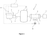
Figure 1 illustrates acompressor 1 comprising acompressor element 2 having agas inlet 3 through which ambient air or a gas from an external source (not shown) is drawn in, and a compressedgas outlet 4 through which compressed gas is provided to a user'snetwork 5. - The
compressor element 2 being driven by a first variable speed (VSD)motor 6. - The compressor further comprising a
controller 7 capable of controlling thevariable speed motor 6. - Preferably, such a compressor further comprises an
aftercooler 8 comprising afan 9, saidfan 9 being driven by asecond VSD motor 10. Thecontroller 7 being able to control saidsecond VSD motor 10. - In the context of the present invention, the
compressor 1 should be understood as the complete compressor installation, including thecompressor element 2, all the typical connection pipes and valves, theaftercooler 8, the housing of thecompressor 1 and possibly thefirst VSD motor 6 and thesecond VSD motor 10. - In the context of the present invention, the
compressor element 2 should be understood as the compressor element casing in which the compression process takes place by means of a rotor or through a reciprocating movement. - In the context of the present invention, said
compressor element 2 can be selected from a group comprising: a screw, a tooth, a claw, a scroll, a rotary vane, a centrifugal, a piston, etc. - By controlling a variable speed motor it should be understood that the
controller 7 generates a signal which is sent through a wired or wireless connection to possibly a local controller of such variable speed motor, said signal being capable of changing the rotational speed of the variable speed motor by increasing or decreasing it. Another possibility is for said signal generated by thecontroller 7 to directly change the rotational speed of the variable speed motor through a wired or wireless connection. - If the connection is wired, such connection typically comprises a wire with two connectors at each end.
- If the connection is wireless, each of the
controller 7 and the variable speed motor, preferably comprises a wireless transceiver capable of sending and receiving a wireless signal. - In one embodiment according to the present invention, the
controller 7 receives data concerning the requirements of the compressed gas through a graphical user interface (not shown) part of saidcontroller 7, or through a main controller (not shown) part of saidcompressor 1 and in communication with saidcontroller 7. - Turning now to
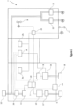
figure 2 , thecontroller 7 comprises arectifier 11 connected to amain power line 12 from the user's premises, receiving alternative current (AC) from said power line and transforming the alternative current into direct current (DC). - A DC link with a DC bus allows for the two inverters to be connected to the two variable speed motors: a
first inverter 13 connected to the firstvariable speed motor 6 and asecond inverter 14 connected to the secondvariable speed motor 10. Said DC bus being a common bus for the two inverters. - The first and second inverter, 13 and 14, would preferably change the DC current into AC current and will also control the frequency and voltage of the signal reaching the first
variable speed motor 6 and the secondvariable speed motor 10. By controlling the frequency and voltage, the speed of the two variable speed motors is controlled such that the demand at the user's network is met. - In a preferred embodiment according to the present invention, each of said first and second inverters, 13 and 14, comprises at least one IGBT (Insulated-Gate Bipolar Transistor) which is connected to said DC bus.
- For a more smooth control, the
controller 7 further comprises aDC link capacitor 15, connected between therectifier 11 and the first and second inverters, 13 and 14, saidcapacitor 15 smoothening the electrical wave form such that the first and second inverters, 13 and 14, will receive a clean smooth signal. - In another embodiment according to the present invention, the
controller 7 can further comprise aseparate cooling fan 26 for cooling the power electronics of saidcontroller 7. - By including such a
separate cooling fan 26, thecontroller 7 will be protected from overheating and thecompressor 1 will not experience a force shut down because of an increased temperature at the level of saidcontroller 7. - In a further embodiment according to the present invention, the
controller 7 further comprises a firstcurrent sensor 17 for sensing the current going through a winding of thefirst VSD motor 6 driving thecompressor element 2. - Said first
current sensor 17 being any type of current sensor such as for example and not limiting thereto: a current clamp meter, a Hall effect Integrated Circuit, a resistor, a fiber optic current sensor, a Rogowski coil. - Preferably, the first
current sensor 17 is selected as a clamp meter, said clamp meter being clamped onto at least two phases of the firstvariable speed motor 6 and of the secondvariable speed motor 10 respectively. It is further possible to have a clamp meter clamped around three phases of said firstvariable speed motor 6 and of said secondvariable speed motor 10 respectively. - Such first
current sensor 17 measuring the current going through the windings of the firstvariable speed motor 6 and secondvariable speed motor 10 respectively, and send such values to aprocessing unit 19 part of thecontroller 7. - Said
processing unit 19 preferably comparing the received measurement with a predetermined current limit and in case the measured current is equal to or higher than the predetermined current limit, the controller unit will stop thecompressor 1, protecting the firstvariable speed motor 6 and the secondvariable speed motor 10 from an overcurrent. - It is further possible to compare the measured current with a first predetermined current limit and if said measured current is equal to or higher than said first predetermined current limit, but lower than a second predetermined current limit, the
controller 7 generates an alert signal on the graphical user interface. However, if the measured current is equal to or higher than the second predetermined current limit, thecontroller 7 stops thecompressor 1. - Further, the measured current is also compared with a minimum predetermined current limit and if the measured current is equal to or lower than such a minimum predetermined current limit, then the
controller 7 stops thecompressor 1. - It should be further not excluded, that the
controller 7 can compare the measured current with more predetermined limits and generate different messages on the graphical user interface, or less predetermined limits and possibly take immediate action and stop thecompressor 1. - In the context of the present invention, it should be understood that the predetermined current limit, the first current limit, the second current limit and the minimum predetermined current limit can have the same values for the measurements on the
first VSD motor 6 as well as for thesecond VSD motor 10, or these values can be different. - Preferably, such values are selected according to the nominal functioning parameters for each of the
first VSD motor 6 and of thesecond VSD motor 10. - In yet another embodiment according to the present invention, the
controller 7 further comprises a secondcurrent sensor 18 for sensing the current going through a winding of thesecond VSD motor 10 driving thefan 9. - Said second
current sensor 18 preferably being a module determining the current going through thesecond VSD motor 10 by applying a voltage over frequency method. Accordingly, the voltage is measured, the frequency of thesecond VSD motor 10 is also retrieved and the current is further determined. - It should be however not excluded that the second
current sensor 18 can be of the same type as the firstcurrent sensor 17. - Tests have shown that by including a first
current sensor 17 and a secondcurrent sensor 18, thecontroller 7 according to the present invention comprises an electrical protection to overcurrent, which is much more reliable and accurate compared to existing controllers typically having a mechanical protection for the current. - In another embodiment according to the present invention, the controller further comprises a
voltage sensor 20 for sensing the value of the voltage at the level of the firstvariable speed motor 6 driving thecompressor element 2 and/or of the secondvariable speed motor 10 driving thefan 9. - Preferably but not limiting thereto, the
voltage sensor 20 is positioned on the DC bus, between therectifier 11 and thecapacitor 15, measuring the voltage of both thefirst VSD motor 6 and of thesecond VSD motor 10. - The
processing unit 19 of saidcontroller 7 preferably comparing the measured voltage with a predetermined voltage limit and if the measured voltage is equal to or higher than said predetermined voltage limit, thecontroller 7 will stop thecompressor 1. - Further, the
processing unit 19 can compare the measured voltage with a predetermined minimum voltage limit and if the measured voltage is equal to or lower than the predetermined minimum voltage, thecontroller 7 will stop thecompressor 1. - It should be further not excluded that the processing unit can compare the measured voltage with more predetermined limits and, depending on the limits, it can generate alerts on the graphical user interface or stop the
compressor 1. - In another embodiment according to the present invention, the
controller 7 further comprises a communication module (not shown) adapted to establish a communication link with an external device (not shown). - A communication link should be understood as a connection between two terminals, allowing for a signal to pass therethrough.
- Such a connection being realized through a wired or wireless medium.
- An external device should be understood as any type of device capable of receiving and transmitting a signal through such a communication link, such as selected from a group comprising: a personal computer, a laptop, a phone, a tablet, a personal digital assistant, the cloud, or any other device.
- The
controller 7 can be further adapted to receive initialization data through such a communication link. - Accordingly, a user of a
compressor 1 according to the present invention can connect to thecontroller 7 remotely and send data such as for example and not limiting thereto: the predetermined current limit, the first current limit, the second current limit and the minimum predetermined current limit, a maximum and a minimum voltage, a predetermined voltage limit, a predetermined minimum voltage limit and possibly additional limits thereof. - It can further receive information concerning a maximum and minimum speed of the
first VSD motor 6 and of thesecond VSD motor 10. - In another embodiment according to the present invention, the
compressor 1 further comprises adryer 21, said dryer typically comprising a third motor (not shown) and a forth motor for driving a fan. - The third motor and the forth motor are preferably each connected to the controller through a Solid State Relay, 22 and 23.
- Each SSR being connected to each of the third motor and the forth motor through a three phase connection. Said third and fourth motor being controlled by the
controller 7 in an ON/OFF manner. - When compared to known controllers, this offers the advantage that the
controller 7 according to the present invention makes thecompressor 1 more durable and that the servicing interventions can be performed at longer time intervals. - In another embodiment according to the present invention, the
controller 7 further comprises a communication link to atemperature sensor 24, saidtemperature sensor 24 being at the level of or in the vicinity of thefirst VSD motor 6. Said temperature sensor sending a measured temperature to the processing unit, whereby it is compared with a minimum threshold and a maximum threshold. - If the measured temperature is equal to or lower than said minimum threshold, the
controller 7 can stop thecompressor 1, or said controller can disconnect the user'snetwork 5 and maintain thefirst VSD motor 6 functioning until the measured temperature is at least equal to said minimum threshold, moment when thecontroller 7 reconnects the user'snetwork 5. - If said measured temperature is equal to or higher than the maximum threshold, the controller unit can stop the
compressor 1. - Such measures protect the
first VSD motor 6 from running at a high load while being at very low temperature, and it also protects it from overheating. - It should be further understood that additional temperature thresholds could be also used, said additional temperature thresholds being selected between the minimum threshold and the maximum threshold. When such thresholds are being reached, the
controller 7 can increase or decrease the speed of thefirst VSD motor 6 such as to control the temperature. - In a further embodiment according to the present invention, the
controller 7 further comprises aninternal power supply 25. Theinternal power supply 25 receiving power from the DC bus and providing power to thefirst VSD motor 6, thesecond VSD motor 10, it can further supply the necessary power to the main controller, and possibly to other components part of thecompressor 1 such as valves, etc. - If the
controller 7 comprises multiple printed circuit boards (PCB), as it is shown in the example offigure 2 , thepower supply 25 can provide the necessary power for each of said PCBs, throughinternal supplies - It should not be excluded that other temperature sensors can also be provided, such as for example and not limiting thereto: a temperature sensor for each of the IGBTs, a temperature sensor for the
internal power supply 25, a temperature sensor for the PCB board of thecontroller 7, even an ambient temperature sensor, etc. - If the temperature of the IGBTs is measured, once such temperature reaches a predetermined threshold, the
controller 7 can increase or decrease the speed of thefirst VSD motor 6 and/or of thesecond VSD motor 10. It could alternately or cumulatively increase or decrease the frequency or the torque of thefirst VSD motor 6 and/or of thesecond VSD motor 10 or it can also stop thefirst VSD motor 6 and/or thesecond VSD motor 10. - If an ambient temperature sensor is provided, if the measured ambient temperature would reach a predetermined ambient threshold, the
controller 7 can decrease the speed of thefirst VSD motor 6 in order to protect it from overheating or can increase such sped in order to maintain a minimum temperature within thecompressor 1. - Further, the
controller 7 can also comprise an ambient humidity sensor. The measured ambient humidity can be used for avoiding condensate formation within one or more of the following: thefirst VSD motor 6, thesecond VSD motor 10, and within thecontroller 7. Accordingly, if the measured ambient humidity is above a humidity limit, the controller can maintain thefirst VSD motor 6 and/or thesecond VSD motor 10 running such that their temperature is maintained relatively high and condensate cannot form. - For maintaining the temperature of the
controller 7 at safe levels thecontroller 7 further comprises a heat sink (not shown) afirst fan 16 for creating an internal flow of air within the housing and asecond fan 27 positioned on the exterior of said housing for cooling the heatsink. - In a preferred embodiment according to the present invention and not limiting thereto, the
rectifier 11, the DC link with the DC bus and the two inverters are on one Printed Circuit Board. - By adopting such a layout, the
controller 7 according to the present invention is even more compact, easier to manufacture and easier to change in case it is damaged. - The
controller 7 according to the present invention not only realizes an efficient protection of thecompressor 1 but it also increases the lifetime of the components part of thecompressor 1. - For further protection the
controller 7 further comprises an AC choke and an EMC (Electromagnetic Compatibility) filter 26 connected between the inlet connector through which thecontroller 7 is connected to themain power line 12 of the user and therectifier 11. - The present invention is further directed to a
compressor 1 comprising acontroller 7 according to the present invention, thecontroller 7 being connected to afirst VSD motor 6 for driving acompressor element 2 and further connected to asecond VSD motor 10 for driving a coolingfan 9 configured to cool said compressor. - In a preferred embodiment according to the present invention, said
compressor 1 does not have a relay cabinet. - Because of this the
compressor 1 according to the present invention is much less complex. - It should however not be excluded that the
controller 107 according to the present invention can be also provided within avacuum pump 101, as illustrated infigure 3 . - If such a
controller 107 is provided in avacuum pump 101, the system would be similar as for acompressor 1, the only difference would be that thegas inlet 103 receives gas from a user'snetwork 105, and thevacuum outlet 104 is connected to the environment or to anexternal network 111. - Similarly to the
compressor 1 offigure 1 , thevacuum pump 101 comprises avacuum element 102 being driven by a firstvariable speed motor 106. Thevacuum pump 101 further comprising atemperature sensor 124. - Further similarly, the
vacuum pump 101 further comprises adryer 121 and anaftercooler 108 comprising afan 109 driven by a secondvariable speed motor 110. - The present invention is by no means limited to the embodiments described as an example and shown in the drawings, but such a
controller 7 can be realized in other kinds of variants, without departing from the scope of the claims.
Claims (11)
- Compressor installation, suitable for compressing a gas and providing it to further components, comprising a compressor (1),
a controller (7) connected to a first VSD motor (6) for driving a compressor element (2) of said compressor (1), an aftercooler (8), and a second VSD motor (10) for driving a cooling fan (9) configured to cool said aftercooler (8), characterized in that said controller (7) comprises a housing in which is provided a rectifier (11), a DC link with a DC bus and two inverters (13, 14) connected to the same DC bus, a first inverter (13) configured to control the first VSD motor (6), and a second inverter (14) configured to control the second VSD motor (10). - Compressor installation according to claim 1, characterized in that said compressor (1) does not have a relay cabinet.
- Compressor installation according to claim 1, characterized in that each of said inverters (13, 14) comprises at least one IGBT which is connected to said DC bus.
- Compressor installation according to claim 1, characterized in that the controller (7) further comprises a separate cooling fan (26) for cooling said power electronics of said controller (7).
- Compressor installation according to any of the previous claims, characterized in that the controller (7) further comprises a first current sensor (17) for sensing the current going through a winding of the first VSD motor (6).
- Compressor installation according to any of the previous claims, characterized in that the controller (7) further comprises a voltage sensor (20) for sensing the value of the voltage at the level of the first VSD motor (6) and/or of the second VSD motor (10) .
- Compressor installation according to any of the previous claims, characterized in that the controller (7) further comprises a communication module adapted to establish a communication link with an external device.
- Compressor installation according to any of the previous claims, characterized in that the controller (7) further comprises a communication link to a temperature sensor (24), said temperature sensor (24) being at the level of or in the vicinity of the first VSD motor (6) driving the compressor element (2).
- Compressor installation according to any of the previous claims, characterized in that the controller (7) further comprises an internal power supply (25).
- Compressor installation according to any of the previous claims, characterized in that the rectifier (11), the DC link with the DC bus and the two inverters (13, 14) are on one Printed Circuit Board.
- Vacuum pump comprising a controller (107) connected to a first VSD motor (106) for driving a vacuum element (102) of said vacuum pump (101) an aftercooler (108), and a second VSD motor (110) for driving a cooling fan (109) configured to cool said aftercooler (108), characterised in that said controller (107) comprises a housing in which is provided a rectifier (11), a DC link with a DC bus and two inverters (13, 14) connected to the same DC bus, a first inverter (13) configured to control the first VSD motor (106) and a second inverter (14) configured to control the second VSD motor (110).
Applications Claiming Priority (2)
| Application Number | Priority Date | Filing Date | Title |
|---|---|---|---|
| US201662321418P | 2016-04-12 | 2016-04-12 | |
| PCT/IB2017/052086 WO2017178970A1 (en) | 2016-04-12 | 2017-04-11 | Controller for compressor |
Publications (2)
| Publication Number | Publication Date |
|---|---|
| EP3443226A1 EP3443226A1 (en) | 2019-02-20 |
| EP3443226B1 true EP3443226B1 (en) | 2024-10-09 |
Family
ID=58638630
Family Applications (1)
| Application Number | Title | Priority Date | Filing Date |
|---|---|---|---|
| EP17719344.8A Active EP3443226B1 (en) | 2016-04-12 | 2017-04-11 | Controller for compressor |
Country Status (13)
| Country | Link |
|---|---|
| US (1) | US11530858B2 (en) |
| EP (1) | EP3443226B1 (en) |
| JP (1) | JP3220956U (en) |
| KR (1) | KR200493290Y1 (en) |
| CN (1) | CN206738136U (en) |
| BE (1) | BE1024219B1 (en) |
| BR (1) | BR212018070780Y1 (en) |
| ES (2) | ES1223434Y (en) |
| FI (1) | FI3443226T3 (en) |
| HU (1) | HUE069767T2 (en) |
| PL (1) | PL3443226T3 (en) |
| RU (1) | RU195344U1 (en) |
| WO (1) | WO2017178970A1 (en) |
Families Citing this family (4)
| Publication number | Priority date | Publication date | Assignee | Title |
|---|---|---|---|---|
| US10935579B2 (en) | 2018-06-18 | 2021-03-02 | Atlas Copco Airpower, Naamloze Vennootschap | Current sensor |
| EP4208678A4 (en) * | 2020-09-01 | 2024-10-09 | Johnson Controls Tyco IP Holdings LLP | Electrical enclosure for hvac system |
| KR20230126936A (en) * | 2022-02-24 | 2023-08-31 | 한온시스템 주식회사 | Residual voltage controller and electric compressor |
| CN117287817B (en) * | 2023-11-03 | 2024-05-28 | 上海耀杉电子科技有限公司 | Method for controlling start-up of compressor, air conditioner, and readable storage medium |
Citations (13)
| Publication number | Priority date | Publication date | Assignee | Title |
|---|---|---|---|---|
| US6397611B1 (en) | 1999-06-04 | 2002-06-04 | Hitachi, Ltd. | Air conditioner and brushless motor control unit |
| DE60123321T2 (en) | 2000-05-17 | 2007-04-05 | Atlas Copco Airpower N.V. | Compressor system with a controlled cooling fan |
| EP1950509A1 (en) * | 2005-10-21 | 2008-07-30 | Daikin Industries, Ltd. | Refrigeration device for trailer |
| DE102009024336A1 (en) | 2009-06-09 | 2010-12-23 | Oerlikon Leybold Vacuum Gmbh | vacuum pump |
| US20110030396A1 (en) | 2009-08-10 | 2011-02-10 | Emerson Electric Co. | HVAC Condenser Assemblies Having Controllable Input Voltages |
| JP2012090412A (en) | 2010-10-19 | 2012-05-10 | Denso Corp | Rotary electric machine |
| JP2012135157A (en) | 2010-12-22 | 2012-07-12 | Daikin Ind Ltd | Motor drive system |
| US20120187764A1 (en) * | 2011-01-24 | 2012-07-26 | Rocky Research | Enclosure housing electronic components having hybrid hvac/r system with power back-up |
| US20120297819A1 (en) | 2011-05-27 | 2012-11-29 | Roger Carlos Becerra | Methods and systems for providing combined blower motor and draft inducer motor control |
| CN202789463U (en) | 2012-07-05 | 2013-03-13 | 鞍山力邦科技有限公司 | Oilless air compressor all-digital intelligent control system |
| CN104141604A (en) | 2014-06-30 | 2014-11-12 | 深圳市英威腾电气股份有限公司 | Frequency converter special for air compressor and air compressor variable-frequency drive control system |
| CN204253322U (en) | 2014-11-05 | 2015-04-08 | 宁波欣达螺杆压缩机有限公司 | Permanent-magnetic variable-frequency air compressor |
| DE102013113557A1 (en) | 2013-12-05 | 2015-06-11 | Knorr-Bremse Systeme für Schienenfahrzeuge GmbH | Compressor system for a railway vehicle and method for operating the compressor system with a safe emergency operation |
Family Cites Families (22)
| Publication number | Priority date | Publication date | Assignee | Title |
|---|---|---|---|---|
| US4044285A (en) * | 1975-08-19 | 1977-08-23 | General Electric Company | Method and apparatus for controlling variable speed, controlled current induction motor drive systems |
| US5695325A (en) * | 1995-10-04 | 1997-12-09 | Sperry; Lauren D. | Synchronized unloader system and method for a gas compressor |
| RU2184258C2 (en) * | 2000-06-19 | 2002-06-27 | Новиков Михаил Иванович | Gas turbine engine control system |
| JP4460202B2 (en) * | 2001-12-28 | 2010-05-12 | パナソニック電工株式会社 | Discharge lamp lighting device |
| US20040244393A1 (en) * | 2003-04-18 | 2004-12-09 | Ingersoll-Rand Company | Variable speed compressor cooling system |
| US7619906B2 (en) * | 2005-03-01 | 2009-11-17 | York International Corporation | System for precharging a DC link in a variable speed drive |
| US7332885B2 (en) * | 2005-09-02 | 2008-02-19 | Johnson Controls Technology Company | Ride-through method and system for HVAC&R chillers |
| US20070151272A1 (en) * | 2006-01-03 | 2007-07-05 | York International Corporation | Electronic control transformer using DC link voltage |
| WO2009096968A1 (en) * | 2008-01-31 | 2009-08-06 | Carrier Corporation | Rapid compressor cycling |
| WO2010120519A2 (en) * | 2009-03-31 | 2010-10-21 | Johnson Controls Technology Company | Control system for operating condenser fans |
| KR20110014435A (en) * | 2009-08-05 | 2011-02-11 | 엘지전자 주식회사 | Air conditioner |
| US8603152B2 (en) * | 2009-12-18 | 2013-12-10 | Scion Neurostim, Llc | Devices and methods for vestibular and/or cranial nerve stimulation |
| DE102009050232B4 (en) * | 2009-10-21 | 2011-09-22 | Sew-Eurodrive Gmbh & Co. Kg | electrical appliance |
| RU97455U1 (en) * | 2010-04-16 | 2010-09-10 | Федеральное государственное унитарное предприятие "Московское машиностроительное производственное предприятие "САЛЮТ" (ФГУП "ММПП "САЛЮТ") | GAS-TURBINE ENGINE COMPRESSOR POSITION CONTROL DEVICE |
| JP2013537598A (en) * | 2010-08-20 | 2013-10-03 | マック トラックス インコーポレイテッド | Heating device for aftertreatment of exhaust gas of internal combustion engine |
| US9052536B2 (en) * | 2011-05-10 | 2015-06-09 | Anthony, Inc. | Display case door with transparent LCD panel |
| WO2012176339A1 (en) * | 2011-06-24 | 2012-12-27 | 富士通株式会社 | Monitoring processing device, electronic system, method for controlling electronic system, and program for controlling monitoring processing device |
| US9437093B2 (en) * | 2011-10-06 | 2016-09-06 | Microchip Technology Incorporated | Differential current measurements to determine ION current in the presence of leakage current |
| US10378533B2 (en) * | 2011-12-06 | 2019-08-13 | Bitzer Us, Inc. | Control for compressor unloading system |
| US9671839B2 (en) * | 2013-03-15 | 2017-06-06 | Dell Products L.P. | Information handling system dynamic acoustical management |
| JP6359957B2 (en) * | 2014-11-20 | 2018-07-18 | ファナック株式会社 | Motor drive device having secondary damage prevention function |
| US10330099B2 (en) * | 2015-04-01 | 2019-06-25 | Trane International Inc. | HVAC compressor prognostics |
-
2017
- 2017-04-11 US US16/089,962 patent/US11530858B2/en active Active
- 2017-04-11 FI FIEP17719344.8T patent/FI3443226T3/en active
- 2017-04-11 EP EP17719344.8A patent/EP3443226B1/en active Active
- 2017-04-11 PL PL17719344.8T patent/PL3443226T3/en unknown
- 2017-04-11 ES ES201890020U patent/ES1223434Y/en active Active
- 2017-04-11 BR BR212018070780-0U patent/BR212018070780Y1/en active IP Right Grant
- 2017-04-11 WO PCT/IB2017/052086 patent/WO2017178970A1/en not_active Ceased
- 2017-04-11 JP JP2018600132U patent/JP3220956U/en active Active
- 2017-04-11 HU HUE17719344A patent/HUE069767T2/en unknown
- 2017-04-11 KR KR2020187000089U patent/KR200493290Y1/en active Active
- 2017-04-11 BE BE2017/5254A patent/BE1024219B1/en active IP Right Grant
- 2017-04-11 RU RU2019132432U patent/RU195344U1/en active
- 2017-04-11 ES ES17719344T patent/ES3007707T3/en active Active
- 2017-04-12 CN CN201720383890.8U patent/CN206738136U/en active Active
Patent Citations (13)
| Publication number | Priority date | Publication date | Assignee | Title |
|---|---|---|---|---|
| US6397611B1 (en) | 1999-06-04 | 2002-06-04 | Hitachi, Ltd. | Air conditioner and brushless motor control unit |
| DE60123321T2 (en) | 2000-05-17 | 2007-04-05 | Atlas Copco Airpower N.V. | Compressor system with a controlled cooling fan |
| EP1950509A1 (en) * | 2005-10-21 | 2008-07-30 | Daikin Industries, Ltd. | Refrigeration device for trailer |
| DE102009024336A1 (en) | 2009-06-09 | 2010-12-23 | Oerlikon Leybold Vacuum Gmbh | vacuum pump |
| US20110030396A1 (en) | 2009-08-10 | 2011-02-10 | Emerson Electric Co. | HVAC Condenser Assemblies Having Controllable Input Voltages |
| JP2012090412A (en) | 2010-10-19 | 2012-05-10 | Denso Corp | Rotary electric machine |
| JP2012135157A (en) | 2010-12-22 | 2012-07-12 | Daikin Ind Ltd | Motor drive system |
| US20120187764A1 (en) * | 2011-01-24 | 2012-07-26 | Rocky Research | Enclosure housing electronic components having hybrid hvac/r system with power back-up |
| US20120297819A1 (en) | 2011-05-27 | 2012-11-29 | Roger Carlos Becerra | Methods and systems for providing combined blower motor and draft inducer motor control |
| CN202789463U (en) | 2012-07-05 | 2013-03-13 | 鞍山力邦科技有限公司 | Oilless air compressor all-digital intelligent control system |
| DE102013113557A1 (en) | 2013-12-05 | 2015-06-11 | Knorr-Bremse Systeme für Schienenfahrzeuge GmbH | Compressor system for a railway vehicle and method for operating the compressor system with a safe emergency operation |
| CN104141604A (en) | 2014-06-30 | 2014-11-12 | 深圳市英威腾电气股份有限公司 | Frequency converter special for air compressor and air compressor variable-frequency drive control system |
| CN204253322U (en) | 2014-11-05 | 2015-04-08 | 宁波欣达螺杆压缩机有限公司 | Permanent-magnetic variable-frequency air compressor |
Also Published As
| Publication number | Publication date |
|---|---|
| JP3220956U (en) | 2019-04-18 |
| US11530858B2 (en) | 2022-12-20 |
| FI3443226T3 (en) | 2025-01-10 |
| KR20180003372U (en) | 2018-12-03 |
| CN206738136U (en) | 2017-12-12 |
| PL3443226T3 (en) | 2025-02-24 |
| KR200493290Y1 (en) | 2021-03-05 |
| ES3007707T3 (en) | 2025-03-20 |
| BE1024219A1 (en) | 2017-12-13 |
| RU195344U1 (en) | 2020-01-23 |
| HUE069767T2 (en) | 2025-04-28 |
| ES1223434U (en) | 2019-01-21 |
| EP3443226A1 (en) | 2019-02-20 |
| BR212018070780Y1 (en) | 2023-04-04 |
| BR212018070780U2 (en) | 2018-12-18 |
| ES1223434Y (en) | 2019-04-11 |
| US20190113263A1 (en) | 2019-04-18 |
| BE1024219B1 (en) | 2017-12-19 |
| WO2017178970A1 (en) | 2017-10-19 |
Similar Documents
| Publication | Publication Date | Title |
|---|---|---|
| EP3443226B1 (en) | Controller for compressor | |
| US11546678B2 (en) | Systems and methods for wirelessly communicating within electric motor systems | |
| US10536047B2 (en) | Electric motor controller for high-moisture applications and method of manufacture | |
| KR101482101B1 (en) | Multi-air conditioner | |
| US20210108633A1 (en) | Refrigerant compressor | |
| US8209057B2 (en) | System and method for forming universal control panel | |
| JP2017125504A (en) | System, method and means for connecting and fixing electronic control device to hermetic type compressor, and hermetic type compressor | |
| AU2018101563A4 (en) | Controller for compressor | |
| US11711911B2 (en) | Three-phase electronic control unit for enclosure air conditioners | |
| JP7066879B2 (en) | Power conversion system | |
| JP2007085337A (en) | Vacuum pump device | |
| KR20190076669A (en) | Power converting apparatus and air conditioner including the same | |
| US20250076406A1 (en) | Electrical apparatus and refrigeration cycler | |
| CN117157877A (en) | Adaptive logic board for variable speed drive of heating, ventilation, air conditioning and refrigeration systems | |
| CN121153013A (en) | Environmental condition monitoring system for variable frequency drives | |
| CN115642836A (en) | Zero watt standby power consumption for electronically commutated motors | |
| EP3597915A1 (en) | Refrigeration compressor protection | |
| JP2016066735A (en) | Cooling system for heating element storage device | |
| WO2012009746A1 (en) | Evaporator saver |
Legal Events
| Date | Code | Title | Description |
|---|---|---|---|
| STAA | Information on the status of an ep patent application or granted ep patent |
Free format text: STATUS: UNKNOWN |
|
| STAA | Information on the status of an ep patent application or granted ep patent |
Free format text: STATUS: THE INTERNATIONAL PUBLICATION HAS BEEN MADE |
|
| PUAI | Public reference made under article 153(3) epc to a published international application that has entered the european phase |
Free format text: ORIGINAL CODE: 0009012 |
|
| STAA | Information on the status of an ep patent application or granted ep patent |
Free format text: STATUS: REQUEST FOR EXAMINATION WAS MADE |
|
| 17P | Request for examination filed |
Effective date: 20181009 |
|
| AK | Designated contracting states |
Kind code of ref document: A1 Designated state(s): AL AT BE BG CH CY CZ DE DK EE ES FI FR GB GR HR HU IE IS IT LI LT LU LV MC MK MT NL NO PL PT RO RS SE SI SK SM TR |
|
| AX | Request for extension of the european patent |
Extension state: BA ME |
|
| DAV | Request for validation of the european patent (deleted) | ||
| DAX | Request for extension of the european patent (deleted) | ||
| STAA | Information on the status of an ep patent application or granted ep patent |
Free format text: STATUS: EXAMINATION IS IN PROGRESS |
|
| 17Q | First examination report despatched |
Effective date: 20220113 |
|
| GRAP | Despatch of communication of intention to grant a patent |
Free format text: ORIGINAL CODE: EPIDOSNIGR1 |
|
| STAA | Information on the status of an ep patent application or granted ep patent |
Free format text: STATUS: GRANT OF PATENT IS INTENDED |
|
| INTG | Intention to grant announced |
Effective date: 20231204 |
|
| GRAS | Grant fee paid |
Free format text: ORIGINAL CODE: EPIDOSNIGR3 |
|
| GRAA | (expected) grant |
Free format text: ORIGINAL CODE: 0009210 |
|
| STAA | Information on the status of an ep patent application or granted ep patent |
Free format text: STATUS: THE PATENT HAS BEEN GRANTED |
|
| AK | Designated contracting states |
Kind code of ref document: B1 Designated state(s): AL AT BE BG CH CY CZ DE DK EE ES FI FR GB GR HR HU IE IS IT LI LT LU LV MC MK MT NL NO PL PT RO RS SE SI SK SM TR |
|
| REG | Reference to a national code |
Ref country code: CH Ref legal event code: EP |
|
| REG | Reference to a national code |
Ref country code: DE Ref legal event code: R096 Ref document number: 602017085346 Country of ref document: DE |
|
| REG | Reference to a national code |
Ref country code: IE Ref legal event code: FG4D |
|
| REG | Reference to a national code |
Ref country code: NL Ref legal event code: FP |
|
| REG | Reference to a national code |
Ref country code: FI Ref legal event code: FGE |
|
| REG | Reference to a national code |
Ref country code: LT Ref legal event code: MG9D |
|
| REG | Reference to a national code |
Ref country code: SE Ref legal event code: TRGR |
|
| P01 | Opt-out of the competence of the unified patent court (upc) registered |
Free format text: CASE NUMBER: APP_263/2025 Effective date: 20250103 |
|
| REG | Reference to a national code |
Ref country code: AT Ref legal event code: MK05 Ref document number: 1730859 Country of ref document: AT Kind code of ref document: T Effective date: 20241009 |
|
| REG | Reference to a national code |
Ref country code: ES Ref legal event code: FG2A Ref document number: 3007707 Country of ref document: ES Kind code of ref document: T3 Effective date: 20250320 |
|
| PG25 | Lapsed in a contracting state [announced via postgrant information from national office to epo] |
Ref country code: HR Free format text: LAPSE BECAUSE OF FAILURE TO SUBMIT A TRANSLATION OF THE DESCRIPTION OR TO PAY THE FEE WITHIN THE PRESCRIBED TIME-LIMIT Effective date: 20241009 Ref country code: PT Free format text: LAPSE BECAUSE OF FAILURE TO SUBMIT A TRANSLATION OF THE DESCRIPTION OR TO PAY THE FEE WITHIN THE PRESCRIBED TIME-LIMIT Effective date: 20250210 Ref country code: IS Free format text: LAPSE BECAUSE OF FAILURE TO SUBMIT A TRANSLATION OF THE DESCRIPTION OR TO PAY THE FEE WITHIN THE PRESCRIBED TIME-LIMIT Effective date: 20250209 |
|
| PGFP | Annual fee paid to national office [announced via postgrant information from national office to epo] |
Ref country code: FI Payment date: 20250107 Year of fee payment: 9 |
|
| PG25 | Lapsed in a contracting state [announced via postgrant information from national office to epo] |
Ref country code: BG Free format text: LAPSE BECAUSE OF FAILURE TO SUBMIT A TRANSLATION OF THE DESCRIPTION OR TO PAY THE FEE WITHIN THE PRESCRIBED TIME-LIMIT Effective date: 20241009 |
|
| PGFP | Annual fee paid to national office [announced via postgrant information from national office to epo] |
Ref country code: SE Payment date: 20250108 Year of fee payment: 9 |
|
| PG25 | Lapsed in a contracting state [announced via postgrant information from national office to epo] |
Ref country code: NO Free format text: LAPSE BECAUSE OF FAILURE TO SUBMIT A TRANSLATION OF THE DESCRIPTION OR TO PAY THE FEE WITHIN THE PRESCRIBED TIME-LIMIT Effective date: 20250109 |
|
| PG25 | Lapsed in a contracting state [announced via postgrant information from national office to epo] |
Ref country code: LV Free format text: LAPSE BECAUSE OF FAILURE TO SUBMIT A TRANSLATION OF THE DESCRIPTION OR TO PAY THE FEE WITHIN THE PRESCRIBED TIME-LIMIT Effective date: 20241009 Ref country code: GR Free format text: LAPSE BECAUSE OF FAILURE TO SUBMIT A TRANSLATION OF THE DESCRIPTION OR TO PAY THE FEE WITHIN THE PRESCRIBED TIME-LIMIT Effective date: 20250110 Ref country code: AT Free format text: LAPSE BECAUSE OF FAILURE TO SUBMIT A TRANSLATION OF THE DESCRIPTION OR TO PAY THE FEE WITHIN THE PRESCRIBED TIME-LIMIT Effective date: 20241009 |
|
| PGFP | Annual fee paid to national office [announced via postgrant information from national office to epo] |
Ref country code: CZ Payment date: 20241223 Year of fee payment: 9 |
|
| PGFP | Annual fee paid to national office [announced via postgrant information from national office to epo] |
Ref country code: IT Payment date: 20250325 Year of fee payment: 9 |
|
| REG | Reference to a national code |
Ref country code: HU Ref legal event code: AG4A Ref document number: E069767 Country of ref document: HU |
|
| PG25 | Lapsed in a contracting state [announced via postgrant information from national office to epo] |
Ref country code: RS Free format text: LAPSE BECAUSE OF FAILURE TO SUBMIT A TRANSLATION OF THE DESCRIPTION OR TO PAY THE FEE WITHIN THE PRESCRIBED TIME-LIMIT Effective date: 20250109 |
|
| PGFP | Annual fee paid to national office [announced via postgrant information from national office to epo] |
Ref country code: TR Payment date: 20250102 Year of fee payment: 9 |
|
| PGFP | Annual fee paid to national office [announced via postgrant information from national office to epo] |
Ref country code: NL Payment date: 20250427 Year of fee payment: 9 |
|
| PGFP | Annual fee paid to national office [announced via postgrant information from national office to epo] |
Ref country code: LU Payment date: 20250428 Year of fee payment: 9 |
|
| PG25 | Lapsed in a contracting state [announced via postgrant information from national office to epo] |
Ref country code: SM Free format text: LAPSE BECAUSE OF FAILURE TO SUBMIT A TRANSLATION OF THE DESCRIPTION OR TO PAY THE FEE WITHIN THE PRESCRIBED TIME-LIMIT Effective date: 20241009 |
|
| PGFP | Annual fee paid to national office [announced via postgrant information from national office to epo] |
Ref country code: PL Payment date: 20250402 Year of fee payment: 9 |
|
| REG | Reference to a national code |
Ref country code: DE Ref legal event code: R026 Ref document number: 602017085346 Country of ref document: DE |
|
| PG25 | Lapsed in a contracting state [announced via postgrant information from national office to epo] |
Ref country code: DK Free format text: LAPSE BECAUSE OF FAILURE TO SUBMIT A TRANSLATION OF THE DESCRIPTION OR TO PAY THE FEE WITHIN THE PRESCRIBED TIME-LIMIT Effective date: 20241009 |
|
| PGFP | Annual fee paid to national office [announced via postgrant information from national office to epo] |
Ref country code: ES Payment date: 20250505 Year of fee payment: 9 Ref country code: GB Payment date: 20250428 Year of fee payment: 9 |
|
| PLBI | Opposition filed |
Free format text: ORIGINAL CODE: 0009260 |
|
| PGFP | Annual fee paid to national office [announced via postgrant information from national office to epo] |
Ref country code: BE Payment date: 20250428 Year of fee payment: 9 |
|
| PG25 | Lapsed in a contracting state [announced via postgrant information from national office to epo] |
Ref country code: EE Free format text: LAPSE BECAUSE OF FAILURE TO SUBMIT A TRANSLATION OF THE DESCRIPTION OR TO PAY THE FEE WITHIN THE PRESCRIBED TIME-LIMIT Effective date: 20241009 |
|
| PGFP | Annual fee paid to national office [announced via postgrant information from national office to epo] |
Ref country code: FR Payment date: 20250425 Year of fee payment: 9 |
|
| PLAX | Notice of opposition and request to file observation + time limit sent |
Free format text: ORIGINAL CODE: EPIDOSNOBS2 |
|
| PG25 | Lapsed in a contracting state [announced via postgrant information from national office to epo] |
Ref country code: RO Free format text: LAPSE BECAUSE OF FAILURE TO SUBMIT A TRANSLATION OF THE DESCRIPTION OR TO PAY THE FEE WITHIN THE PRESCRIBED TIME-LIMIT Effective date: 20241009 |
|
| PG25 | Lapsed in a contracting state [announced via postgrant information from national office to epo] |
Ref country code: SK Free format text: LAPSE BECAUSE OF FAILURE TO SUBMIT A TRANSLATION OF THE DESCRIPTION OR TO PAY THE FEE WITHIN THE PRESCRIBED TIME-LIMIT Effective date: 20241009 |
|
| PGFP | Annual fee paid to national office [announced via postgrant information from national office to epo] |
Ref country code: IE Payment date: 20250428 Year of fee payment: 9 |
|
| 26 | Opposition filed |
Opponent name: KAESER KOMPRESSOREN SE Effective date: 20250709 |
|
| PGFP | Annual fee paid to national office [announced via postgrant information from national office to epo] |
Ref country code: HU Payment date: 20250804 Year of fee payment: 9 |
|
| PGFP | Annual fee paid to national office [announced via postgrant information from national office to epo] |
Ref country code: DE Payment date: 20250827 Year of fee payment: 9 |
|
| REG | Reference to a national code |
Ref country code: CH Ref legal event code: H13 Free format text: ST27 STATUS EVENT CODE: U-0-0-H10-H13 (AS PROVIDED BY THE NATIONAL OFFICE) Effective date: 20251125 |
|
| PG25 | Lapsed in a contracting state [announced via postgrant information from national office to epo] |
Ref country code: MC Free format text: LAPSE BECAUSE OF FAILURE TO SUBMIT A TRANSLATION OF THE DESCRIPTION OR TO PAY THE FEE WITHIN THE PRESCRIBED TIME-LIMIT Effective date: 20241009 |
|
| PG25 | Lapsed in a contracting state [announced via postgrant information from national office to epo] |
Ref country code: CH Free format text: LAPSE BECAUSE OF NON-PAYMENT OF DUE FEES Effective date: 20250430 |
|
| RDAF | Communication despatched that patent is revoked |
Free format text: ORIGINAL CODE: EPIDOSNREV1 |