EP3443218B1 - Method and apparatus to control an ignition system - Google Patents
Method and apparatus to control an ignition system Download PDFInfo
- Publication number
- EP3443218B1 EP3443218B1 EP17716869.7A EP17716869A EP3443218B1 EP 3443218 B1 EP3443218 B1 EP 3443218B1 EP 17716869 A EP17716869 A EP 17716869A EP 3443218 B1 EP3443218 B1 EP 3443218B1
- Authority
- EP
- European Patent Office
- Prior art keywords
- switches
- switch
- coil
- primary winding
- primary
- Prior art date
- Legal status (The legal status is an assumption and is not a legal conclusion. Google has not performed a legal analysis and makes no representation as to the accuracy of the status listed.)
- Active
Links
Images





Classifications
-
- F—MECHANICAL ENGINEERING; LIGHTING; HEATING; WEAPONS; BLASTING
- F02—COMBUSTION ENGINES; HOT-GAS OR COMBUSTION-PRODUCT ENGINE PLANTS
- F02P—IGNITION, OTHER THAN COMPRESSION IGNITION, FOR INTERNAL-COMBUSTION ENGINES; TESTING OF IGNITION TIMING IN COMPRESSION-IGNITION ENGINES
- F02P15/00—Electric spark ignition having characteristics not provided for in, or of interest apart from, groups F02P1/00 - F02P13/00 and combined with layout of ignition circuits
- F02P15/08—Electric spark ignition having characteristics not provided for in, or of interest apart from, groups F02P1/00 - F02P13/00 and combined with layout of ignition circuits having multiple-spark ignition, i.e. ignition occurring simultaneously at different places in one engine cylinder or in two or more separate engine cylinders
-
- F—MECHANICAL ENGINEERING; LIGHTING; HEATING; WEAPONS; BLASTING
- F02—COMBUSTION ENGINES; HOT-GAS OR COMBUSTION-PRODUCT ENGINE PLANTS
- F02P—IGNITION, OTHER THAN COMPRESSION IGNITION, FOR INTERNAL-COMBUSTION ENGINES; TESTING OF IGNITION TIMING IN COMPRESSION-IGNITION ENGINES
- F02P15/00—Electric spark ignition having characteristics not provided for in, or of interest apart from, groups F02P1/00 - F02P13/00 and combined with layout of ignition circuits
- F02P15/10—Electric spark ignition having characteristics not provided for in, or of interest apart from, groups F02P1/00 - F02P13/00 and combined with layout of ignition circuits having continuous electric sparks
-
- F—MECHANICAL ENGINEERING; LIGHTING; HEATING; WEAPONS; BLASTING
- F02—COMBUSTION ENGINES; HOT-GAS OR COMBUSTION-PRODUCT ENGINE PLANTS
- F02P—IGNITION, OTHER THAN COMPRESSION IGNITION, FOR INTERNAL-COMBUSTION ENGINES; TESTING OF IGNITION TIMING IN COMPRESSION-IGNITION ENGINES
- F02P15/00—Electric spark ignition having characteristics not provided for in, or of interest apart from, groups F02P1/00 - F02P13/00 and combined with layout of ignition circuits
- F02P15/12—Electric spark ignition having characteristics not provided for in, or of interest apart from, groups F02P1/00 - F02P13/00 and combined with layout of ignition circuits having means for strengthening spark during starting
-
- F—MECHANICAL ENGINEERING; LIGHTING; HEATING; WEAPONS; BLASTING
- F02—COMBUSTION ENGINES; HOT-GAS OR COMBUSTION-PRODUCT ENGINE PLANTS
- F02P—IGNITION, OTHER THAN COMPRESSION IGNITION, FOR INTERNAL-COMBUSTION ENGINES; TESTING OF IGNITION TIMING IN COMPRESSION-IGNITION ENGINES
- F02P3/00—Other installations
- F02P3/02—Other installations having inductive energy storage, e.g. arrangements of induction coils
- F02P3/04—Layout of circuits
- F02P3/0407—Opening or closing the primary coil circuit with electronic switching means
-
- F—MECHANICAL ENGINEERING; LIGHTING; HEATING; WEAPONS; BLASTING
- F02—COMBUSTION ENGINES; HOT-GAS OR COMBUSTION-PRODUCT ENGINE PLANTS
- F02P—IGNITION, OTHER THAN COMPRESSION IGNITION, FOR INTERNAL-COMBUSTION ENGINES; TESTING OF IGNITION TIMING IN COMPRESSION-IGNITION ENGINES
- F02P3/00—Other installations
- F02P3/02—Other installations having inductive energy storage, e.g. arrangements of induction coils
- F02P3/04—Layout of circuits
- F02P3/0407—Opening or closing the primary coil circuit with electronic switching means
- F02P3/0435—Opening or closing the primary coil circuit with electronic switching means with semiconductor devices
- F02P3/0442—Opening or closing the primary coil circuit with electronic switching means with semiconductor devices using digital techniques
-
- F—MECHANICAL ENGINEERING; LIGHTING; HEATING; WEAPONS; BLASTING
- F02—COMBUSTION ENGINES; HOT-GAS OR COMBUSTION-PRODUCT ENGINE PLANTS
- F02P—IGNITION, OTHER THAN COMPRESSION IGNITION, FOR INTERNAL-COMBUSTION ENGINES; TESTING OF IGNITION TIMING IN COMPRESSION-IGNITION ENGINES
- F02P3/00—Other installations
- F02P3/02—Other installations having inductive energy storage, e.g. arrangements of induction coils
- F02P3/04—Layout of circuits
- F02P3/045—Layout of circuits for control of the dwell or anti dwell time
- F02P3/0453—Opening or closing the primary coil circuit with semiconductor devices
- F02P3/0456—Opening or closing the primary coil circuit with semiconductor devices using digital techniques
-
- F—MECHANICAL ENGINEERING; LIGHTING; HEATING; WEAPONS; BLASTING
- F02—COMBUSTION ENGINES; HOT-GAS OR COMBUSTION-PRODUCT ENGINE PLANTS
- F02P—IGNITION, OTHER THAN COMPRESSION IGNITION, FOR INTERNAL-COMBUSTION ENGINES; TESTING OF IGNITION TIMING IN COMPRESSION-IGNITION ENGINES
- F02P3/00—Other installations
- F02P3/02—Other installations having inductive energy storage, e.g. arrangements of induction coils
- F02P3/04—Layout of circuits
- F02P3/05—Layout of circuits for control of the magnitude of the current in the ignition coil
- F02P3/051—Opening or closing the primary coil circuit with semiconductor devices
- F02P3/053—Opening or closing the primary coil circuit with semiconductor devices using digital techniques
-
- F—MECHANICAL ENGINEERING; LIGHTING; HEATING; WEAPONS; BLASTING
- F02—COMBUSTION ENGINES; HOT-GAS OR COMBUSTION-PRODUCT ENGINE PLANTS
- F02P—IGNITION, OTHER THAN COMPRESSION IGNITION, FOR INTERNAL-COMBUSTION ENGINES; TESTING OF IGNITION TIMING IN COMPRESSION-IGNITION ENGINES
- F02P3/00—Other installations
- F02P3/02—Other installations having inductive energy storage, e.g. arrangements of induction coils
- F02P3/04—Layout of circuits
- F02P3/055—Layout of circuits with protective means to prevent damage to the circuit, e.g. semiconductor devices or the ignition coil
- F02P3/0552—Opening or closing the primary coil circuit with semiconductor devices
- F02P3/0554—Opening or closing the primary coil circuit with semiconductor devices using digital techniques
Definitions
- the present invention relates to an ignition system and method of controlling spark plugs. It has particular but not exclusive application to systems which are adapted to provide a continuous spark, such as a multi-spark plug ignition system.
- Ignition engines that use very lean air-fuel mixtures have been developed, that is, having a higher air composition to reduce fuel consumption and emissions.
- Prior art systems generally use large, high energy, single spark ignition coils, which have a limited spark duration and energy output.
- multi-charge ignition systems have been developed. Multi-charge systems produce a fast sequence of individual sparks, so that the output is a long quasi-continuous spark.
- Multi-charge ignition methods have the disadvantage that the spark is interrupted during the recharge periods, which has negative effects, particularly noticeable when high turbulences are present in the combustion chamber. For example this can lead to misfire, resulting in higher fuel consumption and higher emissions.
- EP2325476 A1 discloses a multi-charge ignition system without these negative effects and, at least partly, producing a continuous ignition spark over a wide area of burn voltage, delivering an adjustable energy to the spark plug and providing with a burning time of the ignition fire that can be chosen freely.
- One drawback of current systems is the high primary current peak at the initial charge. That current peak is unwanted, it generates higher copper-losses, higher EMC-Emissions and acts as a higher load for the onboard power generation (generator / battery) of the vehicle.
- One option to minimize the high primary current peak is a DC/DC converter in front of the ignition coil (e.g. 48 V). However this introduces extra cost.
- DE 102 31 511 discloses a conventional multi charge ignition system.
- a multi-charge ignition system as claimed in claim 1.
- the system includes a spark plug control unit and at least two coil stages.
- the spark plug control unit is configured to control the two coil stages so as to successively energise and de-energise said coil stage(s) to provide a current to a spark plug.
- the two stages comprise a first transformer (T1) including a first primary winding (L1) inductively coupled to a first secondary winding (L2); a second transformer (T2) including a second primary winding (L3) inductively coupled to a second secondary winding (L4).
- the high sides of the first and secondary primary windings are connected to a common energizing potential.
- the first and second secondary windings are arranged in parallel.
- a first switch means M1 is electrically connected between a voltage supply high side and the high side of the first primary winding, a second switch Q1 is electrically connected between the first primary winding and the power supply low side supply/earth, a third switch is connected between the junction of the first switch and high side end of the first inductor and a point between the low side of the second primary winding and low side supply/earth.
- a fourth switch is located between the low side of the second primary winding and said point, and a fifth switch is located between said point and low side supply/earth.
- a method of operating a system as above including in a non-operational state, setting all switches M1 M2 M3 Q1 Q2 to off.
- a method of operating a system as above including, during an initial ramp-up phase, switching switches Q1, Q2, M3 to on, and M1,M2 to off.
- a method of operating a system as above including, after said initial ramp up stage, switching Q1 and Q2 to off.
- a method of operating a system as above including during a coupled multi-charge phase, setting the switches alternately to/from the following settings a) Q1/M1 on, Q2/M2/M3off and b) Q1/M1/M3 off, Q2/M2 on.
- a method of operating a system as above including, in a step-down phase, setting the switches a) Q2/M1/M3 on, Q1/M2 off and toggling M2/M3.
- a method of operating a system as above including, in a step-down phase Q1/M2/M3 on, Q2/M1 on and toggling M1/M3.
- FIG. 1 shows the circuitry of a prior art coupled-multi-charge ignition system for producing a continuous ignition spark over a wide area of burn voltage servicing a single set of gapped electrodes in a spark plug 11 such as might be associated with a single combustion cylinder of an internal combustion engine (not shown).
- the CMC system uses fast charging ignition coils (L1-L4), including primary windings, L1, L2 to generate the required high DC-voltage.
- L1 and L2 are wound on a common core K1 forming a first transformer (coil stage) and secondary windings L3, L4 wound on another common core K2 are forming a second transformer (coil stage).
- the two coil ends of the first and second primary 20 windings L1, L3 may be alternately switched to a common ground such as a chassis ground of an automobile by electrical switches Q1, Q2.
- These switches Q1, Q2 are preferably Insulated Gate Bipolar Transistors.
- Resistor R1 may be optionally present for measuring the primary current Ip that flows from the primary side and is connected between the switches Q1, Q2 and ground, while optional resistor R2 for measuring the secondary current Is that flows from the secondary side is connected between the diodes D1, D2 and ground.
- the low-voltage ends of the secondary windings L2, L4 may be coupled to a common ground or chassis ground of an automobile through high-voltages diodes D1, D2.
- the high-voltage ends of the secondary ignition windings L2, L4 are coupled to one electrode of a gapped pair of electrodes in a spark plug 11 through conventional means.
- the other electrode of the spark plug 11 is also coupled to a common ground, conventionally by way of threaded engagement of the spark plug to the engine block.
- the primary windings L1, L3 are connected to a common energizing potential which may correspond to conventional automotive system voltage in a nominal 12V automotive electrical system and is in the figure the positive voltage of battery.
- the charge current can be supervised by an electronic control circuit 13 that controls the state of the switches Q1, Q2.
- the control circuit 13 is for example responsive to engine spark timing (EST) signals, supplied by the ECU, to selectively couple the primary windings L1 and L2 to system ground through switches Q1 and Q2 respectively controlled by signals Igbt1 and Igbt2, respectively. Measured primary current Ip and secondary current Is may be sent to control unit 13.
- the common energizing potential of the battery 15 is coupled by way of an ignition switch M1 to the primary windings L1, L3 at the opposite end that the grounded one.
- Switch M1 is preferably a MOSFET transistor.
- a diode D3 or any other semiconductor switch (e.g. MOSFET) is coupled to transistor M1 so as to form a step-down converter.
- Control unit 13 is enabled to switch off switch M1 by means of a signal FET. The diode D3 or any other semiconductor switch will be switched on when M1 is off and vice versa.
- the control circuit 13 is operative to provide an extended continuous high-energy arc across the gapped electrodes.
- switches M1, Q1 and Q2 are all switched on, so that the delivered energy of the power supply 15 is stored in the magnetic circuit of both transformers (T1, T2).
- both primary windings are switched off at the same time by means of switches Q1 and Q2.
- On the secondary side of the transformers a high voltage is induced and an ignition spark is created through the gapped electrodes of the spark plug 11.
- switch Q1 is switched on and switch Q2 is switched off (or vice versa).
- the first transformer (L1, L2) stores energy into its magnetic circuit while the second transformer (L3, L4) delivers energy to spark plug (or vice versa).
- the control unit detects it and switches transistor M1 off.
- the stored energy in the transformer (L1, L2 or L3, L4) that is switched on (Q1, or Q2) impels a current over diode D3 (step-down topology), so that the transformer cannot go into the magnetic saturation, its energy being limited.
- transistor M1 will be permanently switched on and off to hold the energy in the transformer on a constant level.
- steps 3 to 5 will be iterated by sequentially switching on and off switches Q1 and Q2 as long as the control unit switches both switches Q1 and Q2 off.
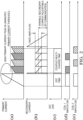
- Figure 2 shows timeline of ignition system current; figure 2a shows a trace representing primary current Ip along time.
- Figure 2b shows the secondary current Is.
- Figure 2c shows the signal on the EST line which is sent from the ECU to the ignition system control unit and which indicates ignition time..
- step 1 i.e. M1, Q1 and Q2 switched on
- the primary current Ip is increasing rapidly with the energy storage in the transformers.
- step 2 i.e. Q1 and Q2 switched off
- the secondary current Is is increasing and a high voltage is induced so as to create an ignition spark through the gapped electrodes of the spark plug.
- step 3 i.e. Q1 and Q2 are switched on and off sequentially, so as to maintain the spark as well as the energy stored in the transformers.
- step 4 comparison is made between primary current Ip and a limit Ipth. When Ip exceeds Ipth M1 is switched off, so that the "switched on” transformer cannot go into the magnetic saturation, by limiting its stored energy. The switch M1 is switched on and off in this way, that the primary current Ip is stable in a controlled range.
- step 5 comparison is made between the secondary current Is and a secondary current threshold level Isth. If Is ⁇ Isth, Q1 is switched off and Q2 switched on (or vice versa). Then steps 3 to 5 will be iterated by sequentially switching on and off Q1 and Q2 as long as the control unit switches both Q1 and Q2 off.
- Figure 3a shows a schematic circuit according to one example - it is similar to that of figure 1 .
- the primary side of the circuit is shown separately to the secondary side of the circuit.e.g. the primary coils are shown separate from the secondary coils.
- the two cores shown in the figure K1 and K2 are each represented twice but in reality there is only one of each; inductor coils L1 and L2 share the same common core K1 and L3 and L4 share the same common core K2.
- a power switch M1 is located similarly arranged to M1 in the figure 1 .
- This switch is located between the power e.g. battery high side and the high side of the coil L1.
- Low sides of the inductor coils L1 and L3 are connected through ground via switches Q1 and Q2.
- a further power switch is connected between the high side of inductor L1 and the low side of inductor L3.
- a further power switch M2 connects the switch Q2 to earth.
- the two secondary coil which are arranged in parallel each have a diode in series connecting the low sides of the coils to earth via the shunt resistor R2, R2 is used to measure the secondary current.
- switches M1, M2, M3, Q1 or Q2 may be controlled by the ECU and/or spark control unit (not shown).
- the circuit needs only one additional power switch.
- the two transformers are connected symmetrically to the battery.
- FIG. 3b shows an alternative example with preferred switches.
- the circuits may include means to measure the voltage at the high voltage HV-diodes (D1 and D2), though this is optional, the supply voltage (Ubat) can additionally and optionally be measured.
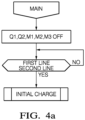
- Figure 4a shows a flow chart of the main loop At the beginning all power switches are off. The coil is waiting in a loop for the control signal (EST signal) from the ECU. When EST is high "Initial Charge” is starting. The process then proceeds to the Initial Charge process.
- EST signal control signal
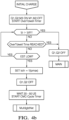
- Figure 4b shows a flow chart for this phase.
- Q1, Q2, M3 are on:
- the current flows through L3, L1 and R1.
- the primary current is measured via R1, if the current is too high both IGBTs are switched off as a safety feature.
- the Tdwell-time is detected, if the time is too high both IGBTs are switched off; this is a safety feature.
- Typical Tdwell time for a CMC-coil is between 600us and 1400 us. Both transformers are charged as long as the EST-signal of the ECU is high. At the falling edge:
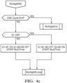
- Figure 4c shows a flow chart for this phase. This program section is used between each toggle cycle. The main goal of this system is to maintain a continuous secondary current and with this to toggle between two characteristic stated:
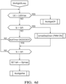
- Figure 4d shows a flow chart of this phase.
- the main goal of this phase on is to measure different current and voltages and to react on it, if the corresponding value is out of range.
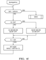
- FIG 4e shows the flow chart of this phase. This phase is initated when the voltage at the HV-diodes is too high and is needed to protect the HV-diodes of too high voltages by switching on both transformers. This is similar to the initial charge phase.
- Figure 4f shows a flow chart of the "MultiIgbtEnd" phase. Here the secondary current is ramped down to zero, this is needed to minimize the spark plug wear. The following steps are taken:
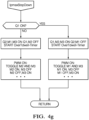
- Figure 4g shows the IpmaxStepDown phase. This function/phase is needed to limit the primary current to a maximum value. In this mode the current flows in a freewheeling path and with this feature the current is limited and with this the stored energy. This function is called during CMC-cycle, where one coil is charged and the other coil is discharged / firing.
- the table of figure 5 below shows the timing: Inside the step-down-state M1 and M3 are toggled (T), when Q1 is switched on resp. M2 and M3 when Q2 is switched on.
- the "MultiIgbtNxt” refers to the CMC-Mode (MultiCharge Mode)
Landscapes
- Engineering & Computer Science (AREA)
- Chemical & Material Sciences (AREA)
- Combustion & Propulsion (AREA)
- Mechanical Engineering (AREA)
- General Engineering & Computer Science (AREA)
- Ignition Installations For Internal Combustion Engines (AREA)
Description
- The present invention relates to an ignition system and method of controlling spark plugs. It has particular but not exclusive application to systems which are adapted to provide a continuous spark, such as a multi-spark plug ignition system.
- Ignition engines that use very lean air-fuel mixtures have been developed, that is, having a higher air composition to reduce fuel consumption and emissions. In order to provide a safe ignition it is necessary to have a high energy ignition source. Prior art systems generally use large, high energy, single spark ignition coils, which have a limited spark duration and energy output. To overcome this limitation and also to reduce the size of the ignition system multi-charge ignition systems have been developed. Multi-charge systems produce a fast sequence of individual sparks, so that the output is a long quasi-continuous spark. Multi-charge ignition methods have the disadvantage that the spark is interrupted during the recharge periods, which has negative effects, particularly noticeable when high turbulences are present in the combustion chamber. For example this can lead to misfire, resulting in higher fuel consumption and higher emissions.
- An improved multi-charge system is described in European Patent application
EP2325476 A1 which discloses a multi-charge ignition system without these negative effects and, at least partly, producing a continuous ignition spark over a wide area of burn voltage, delivering an adjustable energy to the spark plug and providing with a burning time of the ignition fire that can be chosen freely. - One drawback of current systems is the high primary current peak at the initial charge. That current peak is unwanted, it generates higher copper-losses, higher EMC-Emissions and acts as a higher load for the onboard power generation (generator / battery) of the vehicle. One option to minimize the high primary current peak is a DC/DC converter in front of the ignition coil (e.g. 48 V). However this introduces extra cost.
-
DE 102 31 511 discloses a conventional multi charge ignition system. - It is an object of the invention to minimize the high primary current peak without the use of a DC/DC converter.
- In one aspect is provided a multi-charge ignition system as claimed in
claim 1. The system includes a spark plug control unit and at least two coil stages. The spark plug control unit is configured to control the two coil stages so as to successively energise and de-energise said coil stage(s) to provide a current to a spark plug. The two stages comprise a first transformer (T1) including a first primary winding (L1) inductively coupled to a first secondary winding (L2); a second transformer (T2) including a second primary winding (L3) inductively coupled to a second secondary winding (L4). - The high sides of the first and secondary primary windings are connected to a common energizing potential. The first and second secondary windings are arranged in parallel.
- A first switch means M1 is electrically connected between a voltage supply high side and the high side of the first primary winding, a second switch Q1 is electrically connected between the first primary winding and the power supply low side supply/earth, a third switch is connected between the junction of the first switch and high side end of the first inductor and a point between the low side of the second primary winding and low side supply/earth. A fourth switch is located between the low side of the second primary winding and said point, and a fifth switch is located between said point and low side supply/earth.
- In a further aspect is provided a method of operating a system as above including in a non-operational state, setting all switches M1 M2 M3 Q1 Q2 to off.
- In a further aspect is provided a method of operating a system as above including, during an initial ramp-up phase, switching switches Q1, Q2, M3 to on, and M1,M2 to off.
- In a further aspect is provided a method of operating a system as above including, after said initial ramp up stage, switching Q1 and Q2 to off.
- In a further aspect is provided a method of operating a system as above including during a coupled multi-charge phase, setting the switches alternately to/from the following settings a) Q1/M1 on, Q2/M2/M3off and b) Q1/M1/M3 off, Q2/M2 on.
- In a further aspect is provided a method of operating a system as above including, in a step-down phase, setting the switches a) Q2/M1/M3 on, Q1/M2 off and toggling M2/M3.
- In a further aspect is provided a method of operating a system as above including, in a step-down phase Q1/M2/M3 on, Q2/M1 on and toggling M1/M3.
- The invention will now be described by way of example and with reference ot the following drawings of which:
-
Figure 1 shows the circuitry of a prior art coupled-multi-charge ignition system; -
Figure 2 shows timeline of thefigure 1 systems for primary and secondary current, EST signal andcoil 1 switch andcoil 2 switch "on" times; -
Figure 3a shows a circuit of a coupled multi-charge system according to one example, andFigure 3b shows an alternative example with preferred switches. -
Figures 4a to f show flow charts of the methodology of operatiing examples in preferred embodiments, -
Figure 5 shows an operational table. -
Figure 1 shows the circuitry of a prior art coupled-multi-charge ignition system for producing a continuous ignition spark over a wide area of burn voltage servicing a single set of gapped electrodes in aspark plug 11 such as might be associated with a single combustion cylinder of an internal combustion engine (not shown). The CMC system uses fast charging ignition coils (L1-L4), including primary windings, L1, L2 to generate the required high DC-voltage. L1 and L2 are wound on a common core K1 forming a first transformer (coil stage) and secondary windings L3, L4 wound on another common core K2 are forming a second transformer (coil stage).. The two coil ends of the first and second primary 20 windings L1, L3 may be alternately switched to a common ground such as a chassis ground of an automobile by electrical switches Q1, Q2. These switches Q1, Q2 are preferably Insulated Gate Bipolar Transistors. Resistor R1 may be optionally present for measuring the primary current Ip that flows from the primary side and is connected between the switches Q1, Q2 and ground, while optional resistor R2 for measuring the secondary current Is that flows from the secondary side is connected between the diodes D1, D2 and ground. - The low-voltage ends of the secondary windings L2, L4 may be coupled to a common ground or chassis ground of an automobile through high-voltages diodes D1, D2. The high-voltage ends of the secondary ignition windings L2, L4 are coupled to one electrode of a gapped pair of electrodes in a
spark plug 11 through conventional means. The other electrode of thespark plug 11 is also coupled to a common ground, conventionally by way of threaded engagement of the spark plug to the engine block. The primary windings L1, L3 are connected to a common energizing potential which may correspond to conventional automotive system voltage in a nominal 12V automotive electrical system and is in the figure the positive voltage of battery. The charge current can be supervised by anelectronic control circuit 13 that controls the state of the switches Q1, Q2. Thecontrol circuit 13 is for example responsive to engine spark timing (EST) signals, supplied by the ECU, to selectively couple the primary windings L1 and L2 to system ground through switches Q1 and Q2 respectively controlled by signals Igbt1 and Igbt2, respectively. Measured primary current Ip and secondary current Is may be sent to controlunit 13. Advantageously, the common energizing potential of thebattery 15 is coupled by way of an ignition switch M1 to the primary windings L1, L3 at the opposite end that the grounded one. Switch M1 is preferably a MOSFET transistor. A diode D3 or any other semiconductor switch (e.g. MOSFET) is coupled to transistor M1 so as to form a step-down converter.Control unit 13 is enabled to switch off switch M1 by means of a signal FET. The diode D3 or any other semiconductor switch will be switched on when M1 is off and vice versa. - In prior art operation, the
control circuit 13 is operative to provide an extended continuous high-energy arc across the gapped electrodes. During a first step, switches M1, Q1 and Q2 are all switched on, so that the delivered energy of thepower supply 15 is stored in the magnetic circuit of both transformers (T1, T2). During a second step, both primary windings are switched off at the same time by means of switches Q1 and Q2. On the secondary side of the transformers a high voltage is induced and an ignition spark is created through the gapped electrodes of thespark plug 11. During a third step, after a minimum burn time wherein both transformers (T1, T2) are delivering energy, switch Q1 is switched on and switch Q2 is switched off (or vice versa). That means that the first transformer (L1, L2) stores energy into its magnetic circuit while the second transformer (L3, L4) delivers energy to spark plug (or vice versa). During a fourth step, when the primary current Ip increases over a limit (Ipmax), the control unit detects it and switches transistor M1 off. The stored energy in the transformer (L1, L2 or L3, L4) that is switched on (Q1, or Q2) impels a current over diode D3 (step-down topology), so that the transformer cannot go into the magnetic saturation, its energy being limited. Preferably, transistor M1 will be permanently switched on and off to hold the energy in the transformer on a constant level. During a fifth step, just after the secondary current Is falls short of a secondary current threshold level (Ismin) the switch Q1 is switched off and the switch Q2 is switched on (or vice versa). Then steps 3 to 5 will be iterated by sequentially switching on and off switches Q1 and Q2 as long as the control unit switches both switches Q1 and Q2 off. -
Figure 2 shows timeline of ignition system current;figure 2a shows a trace representing primary current Ip along time.Figure 2b shows the secondary current Is.Figure 2c shows the signal on the EST line which is sent from the ECU to the ignition system control unit and which indicates ignition time.. Duringstep 1, i.e. M1, Q1 and Q2 switched on, the primary current Ip is increasing rapidly with the energy storage in the transformers. Duringstep 2, i.e. Q1 and Q2 switched off, the secondary current Is is increasing and a high voltage is induced so as to create an ignition spark through the gapped electrodes of the spark plug. During step 3, i.e. Q1 and Q2 are switched on and off sequentially, so as to maintain the spark as well as the energy stored in the transformers. During step 4, comparison is made between primary current Ip and a limit Ipth. When Ip exceeds Ipth M1 is switched off, so that the "switched on" transformer cannot go into the magnetic saturation, by limiting its stored energy. The switch M1 is switched on and off in this way, that the primary current Ip is stable in a controlled range. During step 5, comparison is made between the secondary current Is and a secondary current threshold level Isth. If Is < Isth, Q1 is switched off and Q2 switched on (or vice versa). Then steps 3 to 5 will be iterated by sequentially switching on and off Q1 and Q2 as long as the control unit switches both Q1 and Q2 off. Because of the alternating charging and discharging of the two transformers the ignition system delivers a continuous ignition fire. The above describes the circuitry and operation of a prior art ignition system to provide a background to the current invention. In some aspects of the invention the above circuitry can be used. The invention provides various solutions to enhance performance and reduce spark-plug wear.Figures 2d and e show the operating states of the respective coils by virtue of the switch on and off times. -
Figure 3a shows a schematic circuit according to one example - it is similar to that offigure 1 . In order for enhanced clarity the primary side of the circuit is shown separately to the secondary side of the circuit.e.g. the primary coils are shown separate from the secondary coils. It is to be understood however that the two cores shown in the figure K1 and K2 are each represented twice but in reality there is only one of each; inductor coils L1 and L2 share the same common core K1 and L3 and L4 share the same common core K2. - In the example a power switch M1 is located similarly arranged to M1 in the
figure 1 . This switch is located between the power e.g. battery high side and the high side of the coil L1. Low sides of the inductor coils L1 and L3 are connected through ground via switches Q1 and Q2. A further power switch is connected between the high side of inductor L1 and the low side of inductor L3.A further power switch M2 connects the switch Q2 to earth.. - On the secondary side the two secondary coil which are arranged in parallel each have a diode in series connecting the low sides of the coils to earth via the shunt resistor R2, R2 is used to measure the secondary current.
- Any of the switches M1, M2, M3, Q1 or Q2 may be controlled by the ECU and/or spark control unit (not shown).
- The circuit needs only one additional power switch. The two transformers are connected symmetrically to the battery.
-
Figure 3b shows an alternative example with preferred switches. - The circuits may include means to measure the voltage at the high voltage HV-diodes (D1 and D2), though this is optional, the supply voltage (Ubat) can additionally and optionally be measured.
- The operation of the circuit according to the examples such as
figure 3a and3 b may be implemented as follows with reference to the flow charts of the drawings. Also at the end of the description is a list of the abbreviations/definitions. -
Figure 4a shows a flow chart of the main loop
At the beginning all power switches are off. The coil is waiting in a loop for the control signal (EST signal) from the ECU. When EST is high "Initial Charge" is starting. The process then proceeds to the Initial Charge process. -
Figure 4b shows a flow chart for this phase. For the initial charge both coil stages are connected in series: Q1, Q2, M3 are on: The current flows through L3, L1 and R1. With this energy is stored in both transformers. The primary current is measured via R1, if the current is too high both IGBTs are switched off as a safety feature. The Tdwell-time is detected, if the time is too high both IGBTs are switched off; this is a safety feature. Typical Tdwell time for a CMC-coil is between 600us and 1400 us. Both transformers are charged as long as the EST-signal of the ECU is high. At the falling edge: - i) First the maximum primary current (Ipmax) is sampled and the secondary current threshold is set as a function of Ipmax. Isth = Ipmax/2/ue - dIs, whereas dIs is a value between ~30 mA to 80 mA
- ii) Both IGBTs Q1 and Q2 are switched off. At this time the high voltage on the secondary side is induced. The ignition spark is generated.
- iii) A small delay time is needed to generate a robust spark, (20 - 50 us) The CMC-cycle timer is started. Typical value for the CMC-Timer is between 500 us (at high RPMs) and 15ms (at low RPMs, e.g.cold start)
- iv) Go to the next step which is "MultiIgbtNxt"
-
Figure 4c shows a flow chart for this phase. This program section is used between each toggle cycle. The main goal of this system is to maintain a continuous secondary current and with this to toggle between two characteristic stated: - Coil1 is charging and
Coil 2 firing : Q1, M1 are on and Q2, M2, M3 are off -
Coil 1 is firing andCoil 2 is charging : Q1, M1, M3 are off and Q2, M2 are on - The following steps are taken:
- i) Checking if the CMC-cycle is finished. The CMC-cycle can be finished via the ECU interface or the CU of the coil via a timer (CMC-Timer).If finished go on with "MultiIgbtEnd"
- ii) Needed to identify the toggling operation. Igbt Q1 is switched on? This means the first CMC-cycle starts always with the coil stage1
- iii) Two possibilities:
- If Q1 was off,
charge coil 1 and fire coil 2 : Q1, M1 are on and Q2, M2, M3 are off. The MultiTimer is started, which is needed to limit the CMC-toggling frequency. - If Q1 was on,
fire coil 1 and charge coil 2 : Q1, M1, M3 are off and Q2, M2 are on. The MultiTimer is started, which is needed to limit the CMC-toggling frequency.
- If Q1 was off,
- iv) Proceed to MultilgbtXLoop phase
-
Figure 4d shows a flow chart of this phase. The main goal of this phase on is to measure different current and voltages and to react on it, if the corresponding value is out of range. - i) The voltage at the diode is monitored. If the voltage is too high go on with MultiIgbtOff ( recharge both coils to protect the HV-diodes)
- ii) Detect the primary current Ip:
- a. Ip higher than IpthCMC too high proceed to "IpmaxStepDown" phase which limits the primary current, then go to step iii). The value of IpthCMC is typically in a range between 15 A and 35 A.
- b. Go to step iii)
- iii) Check the MultiTimer, if the timer has reached an adaptable time, then go on with step i, otherwise go on with step iv). A typical time for the MultiTimer is in the range between 80 us and 500 us.
- iv) Check if the secondary current Is is below the threshold value Isth:
- a. If no, go to step i)
- b. If yes, go to step v) with MuliIgbtNxt ( toggle coil stages)
- v) The secondary current threshold Isth is set as a function of the measured maximum current Ipmax. Then go to the MuliIgbtNxt phase ( toggle coil stages).
-
Figure 4e shows the flow chart of this phase. This phase is initated when the voltage at the HV-diodes is too high and is needed to protect the HV-diodes of too high voltages by switching on both transformers. This is similar to the initial charge phase. - i) Both coil stages are connected in series: Q1, Q2, M3 are on and M1, M2 are off: The current flows through L3, L1 and R1. With this energy is stored in both transformers. The primary current is measured via R1.
- ii) Detect primary current Ip:
- a. Ip higher than Ipth1 than go to step iii) . Ipth1 is in the range between 15 and 35 A.
- b. Recharge both coils as long the primary current reaches the limit
- iii) The maximum primary current (Ipmax) is sampled and the secondary current threshold is set as a function of Ipmax. Isth = Ipmax/2/ue - dIs, whereas dIs is a value between ~30 mA to 80 mA
- iv) Both IGBTs Q1 and Q2 are switched off. At this time the high voltage on the secondary side is induced. The ignition spark is generated.
- v) A small delay time is needed to generate a robust spark, (20 - 50 us)
- vi) Go to the MuliIgbtNxt phase ( toggle coil stages).
-
Figure 4f shows a flow chart of the "MultiIgbtEnd" phase. Here the secondary current is ramped down to zero, this is needed to minimize the spark plug wear. The following steps are taken: - i) If the secondary current threshold Isth, which is used for the ramp down, is below the minimum secondary current threshold, then go on with Main (
figure 4a ) - ii) Which Igbt is on?
- a. Q1 is off: Switch Q1, M2, M3 on and Q2, M1 off. Herewith
coil 1 is firing andcoil 2 is in the freewheeling mode and current flows through L3, Q2, M3, M1 - b. Q1 is on: Switch Q2, M1, M3 on and Q1, M2 off. Herewith
coil 2 is firing andcoil 1 is in the freewheeling mode then current flows through L1, Q1, M3, M2
- a. Q1 is off: Switch Q1, M2, M3 on and Q2, M1 off. Herewith
- iii) Wait until the secondary current Is falls short of Isth, then go to step iv)
- iv) The new secondary current threshold Isth(n) is set dependent on the old Isth(n-1) value: Isth(n) = Isth(n-1) - dIs, whereas dIs is in the range of 20-50 mA.
-
Figure 4g shows the IpmaxStepDown phase. This function/phase is needed to limit the primary current to a maximum value. In this mode the current flows in a freewheeling path and with this feature the current is limited and with this the stored energy. This function is called during CMC-cycle, where one coil is charged and the other coil is discharged / firing. - 1. Which Igbt is on?
- a. Q1is off:
- i.
Coil 2 is switched into the step-down-mode by switching Q2, M1 and M3 on. - ii. Toggle M2 and M3 via a PWM signal the PWM signal is switched on as long as the CMC-cycle is toggled to the next stage (MultiIgbtNxt)
- i.
- b. Q1is on:
- i.
Coil 1 is switched into the step-down-mode by switching Q1, M2 and M3 on. - ii. Toggle M1 and M3 via a PWM signal the PWM signal is switched on as long as the CMC-cycle is toggled to the next stage (MultiIgbtNxt)
- i.
- a. Q1is off:
- The table of
figure 5 below shows the timing: Inside the step-down-state M1 and M3 are toggled (T), when Q1 is switched on resp. M2 and M3 when Q2 is switched on. The "MultiIgbtNxt" refers to the CMC-Mode (MultiCharge Mode) - Below shows a summary of the control of switches for the salient phases
- a) Initially all switches are off at the beginning, whereas it is only important here that no power current flows into the circuit (no closed circuit) Q1 Q2 M1 M2 M3 - all off
- b) For the initial ramp up we are switching Q1/Q2/M3 on, M1/M2off (start over Tdwell-Timer)
- c) Then we are switching all switches off, whereas the most important one are Q1 and Q2, these must be off. The other ones must be switched in that way, that there is no short circuit.
- d) For the CMC-Mode, the switches move from(between) : Q1/M1 on, Q2/M2/M3 off and Q1/M1/M3 off, Q2, M2 on
- L1
- -
Primary inductance coil 1 - L2
- - Secondary inductance coil1
- L3
- -
Primary inductance coil 2 - L4
- -
Secondary inductance coil 2 - K1
- - Magnetic
coupling factor coil 1 - K2
- - Magnetic
coupling factor coil 2 - R1
- - Primary current shunt resistor
- R2
- - Primary current shunt resistor
- Q1
- - IGBT for
coil stage 1 - Q2
- - IGBT for
coil stage 2 - D1
- - High
voltage diode coil 1 - D2
- - High
voltage diode coil 2 - M1
- - Power switch (MOSFET), step down
switch coil 2 - M2
- - Power switch (MOSFET) , step down
switch coil 1 - M3
- - Power switch (MOSFET), series connection and step down switch
- ue
- - winding ratio, between secondary and primary winding
- Ub
- - Battery voltage
- Us
- - Secondary voltage, spark plug voltage
- Ud
- - High voltage diode voltage
- Udthmax
- - High voltage diode switching threshold voltage
- ECU
- - Engine Control Unit
- EST
- - Engine Spark Timing, common name for the control signal coming from the ECU
- CU
- - Control Unit of the ignition coil
- CMC
- - Coupled MultiCharge Ignition
- Ipth
- - Primary current switching threshold in CMC
- Ipth1
- - Primary current switching threshold during the initial charge
- Isth
- - Secondary current switching threshold in CMC
- Ipmax
- - Maximum primary current peak after initial charge
- Ipthmax -
- Maximum primary current switching threshold in step-down-operation
- PWM
- - Pulse Width Modulation
Claims (7)
- A multi-charge ignition system including a spark plug control unit and at least two coil stages, said spark plug control unit being configured to control said at least two coil stages so as to successively energise and de-energise said coil stage(s) to provide a current to a spark plug, wherein said two stages comprise:a first transformer (T1) including a first primary winding (L1) inductively coupled to a first secondary winding (L2);a second transformer (T2) including a second primary winding (L3) inductively coupled to a second secondary winding (L4);the high sides of the first and secondary primary windings being connected to a common energizing potential;wherein said multi-charge ignition system further comprises:a first switch (M1) is electrically connected between a power supply high side and the high side of the first primary winding,a second switch (Q1) is electrically connected between the low side of the first primary winding (L1) and the power supply low side supply/earth,a third switch (M3) is connected between the junction of the first switch (M1) and the high side end ofthe first primary winding (L1) and a point between the low side of the second primary winding (L3) and low side supply/earth, andfurther including a fourth switch (Q2) located between the low side of the second primary winding (L3) and said point, anda fifth switch (M2) located between said point and low side supply/earth.
- A method of operating a system as claimed in claim 1 comprising the steps of, in a non-operational state, setting all switches (M1, M2, M3, Q1, Q2) to off.
- A method according to claim 2, comprising the further steps of, during an initial ramp-up phase, switching the second, third and fourth switches (Q1, M3, Q2) to on, and the first and fifth switches (M1, M2) to off.
- A method according to claim 3, including the steps of, after said initial ramp up stage, switching the second switch (Q1) and the fourth switch (Q2) to off.
- A method according to claim 2, comprising the further steps of, during a coupled multi-charge phase, setting the switches alternately to/from the following settings a) the first and second switches (M1, Q1) to on, the third, fourth and fifth switches (M3, Q2, M2) to off and b) the first, second and third switches (M1, Q1, M3) to off, the fourth and fifth switches (Q2, M2) to on.
- A method according to claim 2, comprising the further steps of, in a step-down phase, setting the switches a) the first, third and fourth switches (M1, M3, Q2) to on, the second and fifth switches (Q1, M2) to off and toggling the fifth switch (M2) with the third switch (M3).
- A method according to claim 2, comprising the steps of setting in a step-down phase the second, third and fifth switches (Q1, M3, M2) to on, the first and fourth switches (M1, Q2) to on and toggling the first switch (M1) with the third switch (M3) .
Applications Claiming Priority (2)
| Application Number | Priority Date | Filing Date | Title |
|---|---|---|---|
| GB1603443.1A GB2549251B (en) | 2016-04-13 | 2016-04-13 | Method and apparatus to control an ignition system |
| PCT/EP2017/058568 WO2017178436A1 (en) | 2016-04-13 | 2017-04-10 | Method and apparatus to control an ignition system |
Publications (2)
| Publication Number | Publication Date |
|---|---|
| EP3443218A1 EP3443218A1 (en) | 2019-02-20 |
| EP3443218B1 true EP3443218B1 (en) | 2025-01-22 |
Family
ID=55807036
Family Applications (1)
| Application Number | Title | Priority Date | Filing Date |
|---|---|---|---|
| EP17716869.7A Active EP3443218B1 (en) | 2016-04-13 | 2017-04-10 | Method and apparatus to control an ignition system |
Country Status (6)
| Country | Link |
|---|---|
| US (1) | US10844825B2 (en) |
| EP (1) | EP3443218B1 (en) |
| KR (1) | KR102323181B1 (en) |
| CN (1) | CN109196220B (en) |
| GB (1) | GB2549251B (en) |
| WO (1) | WO2017178436A1 (en) |
Families Citing this family (8)
| Publication number | Priority date | Publication date | Assignee | Title |
|---|---|---|---|---|
| GB201519699D0 (en) * | 2015-11-09 | 2015-12-23 | Delphi Automotive Systems Lux | Method and apparatus to control an ignition system |
| DE102017216227B3 (en) | 2017-09-13 | 2019-03-07 | Audi Ag | Control circuit for controlling an ignition coil of an internal combustion engine and method for operating such a control circuit |
| US20190280464A1 (en) * | 2018-03-07 | 2019-09-12 | Semiconductor Components Industries, Llc | Ignition control system for a high-voltage battery system |
| US10975827B2 (en) * | 2018-09-26 | 2021-04-13 | Semiconductor Components Industries, Llc | Ignition control system with circulating-current control |
| CN109253013B (en) * | 2018-11-07 | 2019-11-15 | 上海交通大学 | Ignition coil with adjustable discharge breakdown capacity |
| GB2599420B (en) * | 2020-10-01 | 2023-03-29 | Delphi Automotive Systems Lux | Method and apparatus to control an ignition system |
| KR102948496B1 (en) * | 2021-02-05 | 2026-04-03 | 현대자동차 주식회사 | Control system of ignition coil and method thereof |
| JP2025145642A (en) * | 2024-03-22 | 2025-10-03 | ダイヤゼブラ電機株式会社 | Ignition coil |
Family Cites Families (12)
| Publication number | Priority date | Publication date | Assignee | Title |
|---|---|---|---|---|
| US3919993A (en) * | 1974-07-10 | 1975-11-18 | Gen Motors Corp | Internal combustion engine coordinated dual action inductive discharge spark ignition system |
| JP3103852B2 (en) * | 1990-06-20 | 2000-10-30 | アイシン精機株式会社 | Ignition control device for internal combustion engine |
| JPH04284167A (en) * | 1991-03-12 | 1992-10-08 | Aisin Seiki Co Ltd | Ignitor for internal combustion engine |
| JP3482161B2 (en) * | 1999-08-03 | 2003-12-22 | 株式会社日立製作所 | Ignition system for internal combustion engine |
| JP2002004994A (en) * | 2000-06-21 | 2002-01-09 | Hanshin Electric Co Ltd | Ignition device for internal combustion engine |
| DE10231511A1 (en) * | 2002-07-12 | 2004-01-15 | Audi Ag | Ignition coil device for internal combustion engine has combustion current supply device with second transformer device with second drive unit, both transformer secondaries connected to ignition plug |
| JP4691373B2 (en) * | 2005-03-14 | 2011-06-01 | 日立オートモティブシステムズ株式会社 | Spark ignition engine, control device used for the engine, and ignition coil used for the engine |
| US7121270B1 (en) | 2005-08-29 | 2006-10-17 | Vimx Technologies Inc. | Spark generation method and ignition system using same |
| EP2325476B1 (en) * | 2009-11-20 | 2016-04-13 | Delphi Technologies, Inc. | Coupled multi-charge ignition system with an intelligent controlling circuit |
| EP2873850A1 (en) * | 2013-11-14 | 2015-05-20 | Delphi Automotive Systems Luxembourg SA | Method and apparatus to control a multi spark ignition system for an internal combustion engine |
| EP2876298B1 (en) * | 2013-11-21 | 2025-01-08 | Delphi Automotive Systems Luxembourg SA | Method and apparatus to control an ignition system with two coils for one spark plug |
| JP6362375B2 (en) * | 2014-03-26 | 2018-07-25 | ダイヤモンド電機株式会社 | Ignition coil for internal combustion engines |
-
2016
- 2016-04-13 GB GB1603443.1A patent/GB2549251B/en active Active
-
2017
- 2017-04-10 CN CN201780032535.9A patent/CN109196220B/en active Active
- 2017-04-10 WO PCT/EP2017/058568 patent/WO2017178436A1/en not_active Ceased
- 2017-04-10 EP EP17716869.7A patent/EP3443218B1/en active Active
- 2017-04-10 US US16/092,969 patent/US10844825B2/en active Active
- 2017-04-10 KR KR1020187030675A patent/KR102323181B1/en active Active
Also Published As
| Publication number | Publication date |
|---|---|
| US20190162155A1 (en) | 2019-05-30 |
| GB2549251B (en) | 2019-11-13 |
| GB201603443D0 (en) | 2016-04-13 |
| US10844825B2 (en) | 2020-11-24 |
| KR102323181B1 (en) | 2021-11-09 |
| WO2017178436A1 (en) | 2017-10-19 |
| CN109196220A (en) | 2019-01-11 |
| EP3443218A1 (en) | 2019-02-20 |
| GB2549251A (en) | 2017-10-18 |
| KR20180129853A (en) | 2018-12-05 |
| CN109196220B (en) | 2020-08-25 |
Similar Documents
| Publication | Publication Date | Title |
|---|---|---|
| GB2549251B (en) | Method and apparatus to control an ignition system | |
| CN105705773B (en) | Method and apparatus for the multiple-spark discharge ignition system for controlling internal combustion engine | |
| EP3374626B1 (en) | Method and apparatus to control an ignition system | |
| EP3374627B1 (en) | Method and apparatus to control an ignition system | |
| EP2876298B1 (en) | Method and apparatus to control an ignition system with two coils for one spark plug | |
| US12416282B2 (en) | Method and apparatus to control an ignition system |
Legal Events
| Date | Code | Title | Description |
|---|---|---|---|
| STAA | Information on the status of an ep patent application or granted ep patent |
Free format text: STATUS: UNKNOWN |
|
| STAA | Information on the status of an ep patent application or granted ep patent |
Free format text: STATUS: THE INTERNATIONAL PUBLICATION HAS BEEN MADE |
|
| PUAI | Public reference made under article 153(3) epc to a published international application that has entered the european phase |
Free format text: ORIGINAL CODE: 0009012 |
|
| STAA | Information on the status of an ep patent application or granted ep patent |
Free format text: STATUS: REQUEST FOR EXAMINATION WAS MADE |
|
| 17P | Request for examination filed |
Effective date: 20181113 |
|
| AK | Designated contracting states |
Kind code of ref document: A1 Designated state(s): AL AT BE BG CH CY CZ DE DK EE ES FI FR GB GR HR HU IE IS IT LI LT LU LV MC MK MT NL NO PL PT RO RS SE SI SK SM TR |
|
| AX | Request for extension of the european patent |
Extension state: BA ME |
|
| DAV | Request for validation of the european patent (deleted) | ||
| DAX | Request for extension of the european patent (deleted) | ||
| STAA | Information on the status of an ep patent application or granted ep patent |
Free format text: STATUS: EXAMINATION IS IN PROGRESS |
|
| 17Q | First examination report despatched |
Effective date: 20211216 |
|
| P01 | Opt-out of the competence of the unified patent court (upc) registered |
Effective date: 20230327 |
|
| GRAP | Despatch of communication of intention to grant a patent |
Free format text: ORIGINAL CODE: EPIDOSNIGR1 |
|
| STAA | Information on the status of an ep patent application or granted ep patent |
Free format text: STATUS: GRANT OF PATENT IS INTENDED |
|
| INTG | Intention to grant announced |
Effective date: 20240917 |
|
| GRAS | Grant fee paid |
Free format text: ORIGINAL CODE: EPIDOSNIGR3 |
|
| GRAA | (expected) grant |
Free format text: ORIGINAL CODE: 0009210 |
|
| STAA | Information on the status of an ep patent application or granted ep patent |
Free format text: STATUS: THE PATENT HAS BEEN GRANTED |
|
| AK | Designated contracting states |
Kind code of ref document: B1 Designated state(s): AL AT BE BG CH CY CZ DE DK EE ES FI FR GB GR HR HU IE IS IT LI LT LU LV MC MK MT NL NO PL PT RO RS SE SI SK SM TR |
|
| REG | Reference to a national code |
Ref country code: GB Ref legal event code: FG4D |
|
| REG | Reference to a national code |
Ref country code: CH Ref legal event code: EP |
|
| REG | Reference to a national code |
Ref country code: IE Ref legal event code: FG4D |
|
| REG | Reference to a national code |
Ref country code: DE Ref legal event code: R096 Ref document number: 602017087426 Country of ref document: DE |
|
| REG | Reference to a national code |
Ref country code: NL Ref legal event code: MP Effective date: 20250122 |
|
| PG25 | Lapsed in a contracting state [announced via postgrant information from national office to epo] |
Ref country code: NL Free format text: LAPSE BECAUSE OF FAILURE TO SUBMIT A TRANSLATION OF THE DESCRIPTION OR TO PAY THE FEE WITHIN THE PRESCRIBED TIME-LIMIT Effective date: 20250122 |
|
| PG25 | Lapsed in a contracting state [announced via postgrant information from national office to epo] |
Ref country code: RS Free format text: LAPSE BECAUSE OF FAILURE TO SUBMIT A TRANSLATION OF THE DESCRIPTION OR TO PAY THE FEE WITHIN THE PRESCRIBED TIME-LIMIT Effective date: 20250422 |
|
| PG25 | Lapsed in a contracting state [announced via postgrant information from national office to epo] |
Ref country code: FI Free format text: LAPSE BECAUSE OF FAILURE TO SUBMIT A TRANSLATION OF THE DESCRIPTION OR TO PAY THE FEE WITHIN THE PRESCRIBED TIME-LIMIT Effective date: 20250122 |
|
| PG25 | Lapsed in a contracting state [announced via postgrant information from national office to epo] |
Ref country code: PL Free format text: LAPSE BECAUSE OF FAILURE TO SUBMIT A TRANSLATION OF THE DESCRIPTION OR TO PAY THE FEE WITHIN THE PRESCRIBED TIME-LIMIT Effective date: 20250122 |
|
| PGFP | Annual fee paid to national office [announced via postgrant information from national office to epo] |
Ref country code: DE Payment date: 20250317 Year of fee payment: 9 |
|
| PG25 | Lapsed in a contracting state [announced via postgrant information from national office to epo] |
Ref country code: ES Free format text: LAPSE BECAUSE OF FAILURE TO SUBMIT A TRANSLATION OF THE DESCRIPTION OR TO PAY THE FEE WITHIN THE PRESCRIBED TIME-LIMIT Effective date: 20250122 |
|
| REG | Reference to a national code |
Ref country code: LT Ref legal event code: MG9D |
|
| PG25 | Lapsed in a contracting state [announced via postgrant information from national office to epo] |
Ref country code: NO Free format text: LAPSE BECAUSE OF FAILURE TO SUBMIT A TRANSLATION OF THE DESCRIPTION OR TO PAY THE FEE WITHIN THE PRESCRIBED TIME-LIMIT Effective date: 20250422 Ref country code: IS Free format text: LAPSE BECAUSE OF FAILURE TO SUBMIT A TRANSLATION OF THE DESCRIPTION OR TO PAY THE FEE WITHIN THE PRESCRIBED TIME-LIMIT Effective date: 20250522 |
|
| REG | Reference to a national code |
Ref country code: AT Ref legal event code: MK05 Ref document number: 1761639 Country of ref document: AT Kind code of ref document: T Effective date: 20250122 |
|
| PG25 | Lapsed in a contracting state [announced via postgrant information from national office to epo] |
Ref country code: HR Free format text: LAPSE BECAUSE OF FAILURE TO SUBMIT A TRANSLATION OF THE DESCRIPTION OR TO PAY THE FEE WITHIN THE PRESCRIBED TIME-LIMIT Effective date: 20250122 |
|
| PG25 | Lapsed in a contracting state [announced via postgrant information from national office to epo] |
Ref country code: LV Free format text: LAPSE BECAUSE OF FAILURE TO SUBMIT A TRANSLATION OF THE DESCRIPTION OR TO PAY THE FEE WITHIN THE PRESCRIBED TIME-LIMIT Effective date: 20250122 Ref country code: PT Free format text: LAPSE BECAUSE OF FAILURE TO SUBMIT A TRANSLATION OF THE DESCRIPTION OR TO PAY THE FEE WITHIN THE PRESCRIBED TIME-LIMIT Effective date: 20250522 |
|
| PG25 | Lapsed in a contracting state [announced via postgrant information from national office to epo] |
Ref country code: BG Free format text: LAPSE BECAUSE OF FAILURE TO SUBMIT A TRANSLATION OF THE DESCRIPTION OR TO PAY THE FEE WITHIN THE PRESCRIBED TIME-LIMIT Effective date: 20250122 Ref country code: GR Free format text: LAPSE BECAUSE OF FAILURE TO SUBMIT A TRANSLATION OF THE DESCRIPTION OR TO PAY THE FEE WITHIN THE PRESCRIBED TIME-LIMIT Effective date: 20250423 |
|
| PG25 | Lapsed in a contracting state [announced via postgrant information from national office to epo] |
Ref country code: AT Free format text: LAPSE BECAUSE OF FAILURE TO SUBMIT A TRANSLATION OF THE DESCRIPTION OR TO PAY THE FEE WITHIN THE PRESCRIBED TIME-LIMIT Effective date: 20250122 |
|
| PG25 | Lapsed in a contracting state [announced via postgrant information from national office to epo] |
Ref country code: SE Free format text: LAPSE BECAUSE OF FAILURE TO SUBMIT A TRANSLATION OF THE DESCRIPTION OR TO PAY THE FEE WITHIN THE PRESCRIBED TIME-LIMIT Effective date: 20250122 |
|
| PG25 | Lapsed in a contracting state [announced via postgrant information from national office to epo] |
Ref country code: SM Free format text: LAPSE BECAUSE OF FAILURE TO SUBMIT A TRANSLATION OF THE DESCRIPTION OR TO PAY THE FEE WITHIN THE PRESCRIBED TIME-LIMIT Effective date: 20250122 |
|
| PG25 | Lapsed in a contracting state [announced via postgrant information from national office to epo] |
Ref country code: DK Free format text: LAPSE BECAUSE OF FAILURE TO SUBMIT A TRANSLATION OF THE DESCRIPTION OR TO PAY THE FEE WITHIN THE PRESCRIBED TIME-LIMIT Effective date: 20250122 |
|
| PG25 | Lapsed in a contracting state [announced via postgrant information from national office to epo] |
Ref country code: IT Free format text: LAPSE BECAUSE OF FAILURE TO SUBMIT A TRANSLATION OF THE DESCRIPTION OR TO PAY THE FEE WITHIN THE PRESCRIBED TIME-LIMIT Effective date: 20250122 |
|
| PG25 | Lapsed in a contracting state [announced via postgrant information from national office to epo] |
Ref country code: EE Free format text: LAPSE BECAUSE OF FAILURE TO SUBMIT A TRANSLATION OF THE DESCRIPTION OR TO PAY THE FEE WITHIN THE PRESCRIBED TIME-LIMIT Effective date: 20250122 Ref country code: CZ Free format text: LAPSE BECAUSE OF FAILURE TO SUBMIT A TRANSLATION OF THE DESCRIPTION OR TO PAY THE FEE WITHIN THE PRESCRIBED TIME-LIMIT Effective date: 20250122 |
|
| REG | Reference to a national code |
Ref country code: DE Ref legal event code: R097 Ref document number: 602017087426 Country of ref document: DE |
|
| PG25 | Lapsed in a contracting state [announced via postgrant information from national office to epo] |
Ref country code: RO Free format text: LAPSE BECAUSE OF FAILURE TO SUBMIT A TRANSLATION OF THE DESCRIPTION OR TO PAY THE FEE WITHIN THE PRESCRIBED TIME-LIMIT Effective date: 20250122 |
|
| PG25 | Lapsed in a contracting state [announced via postgrant information from national office to epo] |
Ref country code: SK Free format text: LAPSE BECAUSE OF FAILURE TO SUBMIT A TRANSLATION OF THE DESCRIPTION OR TO PAY THE FEE WITHIN THE PRESCRIBED TIME-LIMIT Effective date: 20250122 |
|
| REG | Reference to a national code |
Ref country code: CH Ref legal event code: H13 Free format text: ST27 STATUS EVENT CODE: U-0-0-H10-H13 (AS PROVIDED BY THE NATIONAL OFFICE) Effective date: 20251125 |
|
| PLBE | No opposition filed within time limit |
Free format text: ORIGINAL CODE: 0009261 |
|
| STAA | Information on the status of an ep patent application or granted ep patent |
Free format text: STATUS: NO OPPOSITION FILED WITHIN TIME LIMIT |
|
| PG25 | Lapsed in a contracting state [announced via postgrant information from national office to epo] |
Ref country code: LU Free format text: LAPSE BECAUSE OF NON-PAYMENT OF DUE FEES Effective date: 20250410 |
|
| PG25 | Lapsed in a contracting state [announced via postgrant information from national office to epo] |
Ref country code: MC Free format text: LAPSE BECAUSE OF FAILURE TO SUBMIT A TRANSLATION OF THE DESCRIPTION OR TO PAY THE FEE WITHIN THE PRESCRIBED TIME-LIMIT Effective date: 20250122 |
|
| REG | Reference to a national code |
Ref country code: BE Ref legal event code: MM Effective date: 20250430 |
|
| 26N | No opposition filed |
Effective date: 20251023 |
|
| PG25 | Lapsed in a contracting state [announced via postgrant information from national office to epo] |
Ref country code: BE Free format text: LAPSE BECAUSE OF NON-PAYMENT OF DUE FEES Effective date: 20250430 |
|
| PG25 | Lapsed in a contracting state [announced via postgrant information from national office to epo] |
Ref country code: CH Free format text: LAPSE BECAUSE OF NON-PAYMENT OF DUE FEES Effective date: 20250430 |
|
| PGFP | Annual fee paid to national office [announced via postgrant information from national office to epo] |
Ref country code: GB Payment date: 20260320 Year of fee payment: 10 |
|
| PG25 | Lapsed in a contracting state [announced via postgrant information from national office to epo] |
Ref country code: IE Free format text: LAPSE BECAUSE OF NON-PAYMENT OF DUE FEES Effective date: 20250410 |
|
| PGFP | Annual fee paid to national office [announced via postgrant information from national office to epo] |
Ref country code: FR Payment date: 20260317 Year of fee payment: 10 |