EP3442690B1 - Sieve bed retention system - Google Patents
Sieve bed retention system Download PDFInfo
- Publication number
- EP3442690B1 EP3442690B1 EP17782912.4A EP17782912A EP3442690B1 EP 3442690 B1 EP3442690 B1 EP 3442690B1 EP 17782912 A EP17782912 A EP 17782912A EP 3442690 B1 EP3442690 B1 EP 3442690B1
- Authority
- EP
- European Patent Office
- Prior art keywords
- perforated plate
- housing
- retention system
- end cap
- skirt
- Prior art date
- Legal status (The legal status is an assumption and is not a legal conclusion. Google has not performed a legal analysis and makes no representation as to the accuracy of the status listed.)
- Active
Links
Images

Classifications
-
- B—PERFORMING OPERATIONS; TRANSPORTING
- B01—PHYSICAL OR CHEMICAL PROCESSES OR APPARATUS IN GENERAL
- B01D—SEPARATION
- B01D71/00—Semi-permeable membranes for separation processes or apparatus characterised by the material; Manufacturing processes specially adapted therefor
- B01D71/02—Inorganic material
- B01D71/028—Molecular sieves
-
- B—PERFORMING OPERATIONS; TRANSPORTING
- B01—PHYSICAL OR CHEMICAL PROCESSES OR APPARATUS IN GENERAL
- B01D—SEPARATION
- B01D53/00—Separation of gases or vapours; Recovering vapours of volatile solvents from gases; Chemical or biological purification of waste gases, e.g. engine exhaust gases, smoke, fumes, flue gases, aerosols
- B01D53/02—Separation of gases or vapours; Recovering vapours of volatile solvents from gases; Chemical or biological purification of waste gases, e.g. engine exhaust gases, smoke, fumes, flue gases, aerosols by adsorption, e.g. preparative gas chromatography
- B01D53/04—Separation of gases or vapours; Recovering vapours of volatile solvents from gases; Chemical or biological purification of waste gases, e.g. engine exhaust gases, smoke, fumes, flue gases, aerosols by adsorption, e.g. preparative gas chromatography with stationary adsorbents
- B01D53/0407—Constructional details of adsorbing systems
-
- B—PERFORMING OPERATIONS; TRANSPORTING
- B01—PHYSICAL OR CHEMICAL PROCESSES OR APPARATUS IN GENERAL
- B01D—SEPARATION
- B01D53/00—Separation of gases or vapours; Recovering vapours of volatile solvents from gases; Chemical or biological purification of waste gases, e.g. engine exhaust gases, smoke, fumes, flue gases, aerosols
- B01D53/02—Separation of gases or vapours; Recovering vapours of volatile solvents from gases; Chemical or biological purification of waste gases, e.g. engine exhaust gases, smoke, fumes, flue gases, aerosols by adsorption, e.g. preparative gas chromatography
- B01D53/04—Separation of gases or vapours; Recovering vapours of volatile solvents from gases; Chemical or biological purification of waste gases, e.g. engine exhaust gases, smoke, fumes, flue gases, aerosols by adsorption, e.g. preparative gas chromatography with stationary adsorbents
- B01D53/0407—Constructional details of adsorbing systems
- B01D53/0415—Beds in cartridges
-
- B—PERFORMING OPERATIONS; TRANSPORTING
- B64—AIRCRAFT; AVIATION; COSMONAUTICS
- B64D—EQUIPMENT FOR FITTING IN OR TO AIRCRAFT; FLIGHT SUITS; PARACHUTES; ARRANGEMENT OR MOUNTING OF POWER PLANTS OR PROPULSION TRANSMISSIONS IN AIRCRAFT
- B64D11/00—Passenger or crew accommodation; Flight-deck installations not otherwise provided for
-
- B—PERFORMING OPERATIONS; TRANSPORTING
- B01—PHYSICAL OR CHEMICAL PROCESSES OR APPARATUS IN GENERAL
- B01D—SEPARATION
- B01D2253/00—Adsorbents used in seperation treatment of gases and vapours
- B01D2253/10—Inorganic adsorbents
- B01D2253/106—Silica or silicates
- B01D2253/108—Zeolites
-
- B—PERFORMING OPERATIONS; TRANSPORTING
- B01—PHYSICAL OR CHEMICAL PROCESSES OR APPARATUS IN GENERAL
- B01D—SEPARATION
- B01D2253/00—Adsorbents used in seperation treatment of gases and vapours
- B01D2253/10—Inorganic adsorbents
- B01D2253/116—Molecular sieves other than zeolites
-
- B—PERFORMING OPERATIONS; TRANSPORTING
- B01—PHYSICAL OR CHEMICAL PROCESSES OR APPARATUS IN GENERAL
- B01D—SEPARATION
- B01D2256/00—Main component in the product gas stream after treatment
- B01D2256/12—Oxygen
-
- B—PERFORMING OPERATIONS; TRANSPORTING
- B01—PHYSICAL OR CHEMICAL PROCESSES OR APPARATUS IN GENERAL
- B01D—SEPARATION
- B01D2257/00—Components to be removed
- B01D2257/40—Nitrogen compounds
-
- B—PERFORMING OPERATIONS; TRANSPORTING
- B01—PHYSICAL OR CHEMICAL PROCESSES OR APPARATUS IN GENERAL
- B01D—SEPARATION
- B01D2259/00—Type of treatment
- B01D2259/45—Gas separation or purification devices adapted for specific applications
- B01D2259/4566—Gas separation or purification devices adapted for specific applications for use in transportation means
- B01D2259/4575—Gas separation or purification devices adapted for specific applications for use in transportation means in aeroplanes or space ships
-
- B—PERFORMING OPERATIONS; TRANSPORTING
- B64—AIRCRAFT; AVIATION; COSMONAUTICS
- B64D—EQUIPMENT FOR FITTING IN OR TO AIRCRAFT; FLIGHT SUITS; PARACHUTES; ARRANGEMENT OR MOUNTING OF POWER PLANTS OR PROPULSION TRANSMISSIONS IN AIRCRAFT
- B64D13/00—Arrangements or adaptations of air-treatment apparatus for aircraft crew or passengers, or freight space
- B64D13/06—Arrangements or adaptations of air-treatment apparatus for aircraft crew or passengers, or freight space the air being conditioned
- B64D2013/0603—Environmental Control Systems
- B64D2013/0677—Environmental Control Systems comprising on board oxygen generator systems
-
- B—PERFORMING OPERATIONS; TRANSPORTING
- B64—AIRCRAFT; AVIATION; COSMONAUTICS
- B64D—EQUIPMENT FOR FITTING IN OR TO AIRCRAFT; FLIGHT SUITS; PARACHUTES; ARRANGEMENT OR MOUNTING OF POWER PLANTS OR PROPULSION TRANSMISSIONS IN AIRCRAFT
- B64D2231/00—Emergency oxygen systems
- B64D2231/02—Supply or distribution systems
-
- B—PERFORMING OPERATIONS; TRANSPORTING
- B64—AIRCRAFT; AVIATION; COSMONAUTICS
- B64D—EQUIPMENT FOR FITTING IN OR TO AIRCRAFT; FLIGHT SUITS; PARACHUTES; ARRANGEMENT OR MOUNTING OF POWER PLANTS OR PROPULSION TRANSMISSIONS IN AIRCRAFT
- B64D37/00—Arrangements in connection with fuel supply for power plant
- B64D37/32—Safety measures not otherwise provided for, e.g. preventing explosive conditions
Definitions
- the present invention relates to molecular sieve devices, and more particularly to a molecular sieve retention system to contain and pack particulate material within a molecular sieve unit, and still more particularly to a molecular sieve retention system to contain and pack the particulate material within the molecular sieve unit even after the molecular sieve unit experiences extreme environmental conditions.
- Aircraft On-Board Oxygen Generation Systems/On-Board Inert Gas Generation Systems are designed to separate gases from a pressurized air source in order to supply oxygen enriched air flow to the flight crew, while also supplying oxygen depleted air flow for inerting the fuel tank ullages.
- Such units typically employ molecular sieve gas separation processes, such as but not limited to pressure swing adsorption (PSA), wherein molecular sieve particulate material, such as a zeolite, is packed as a bed and retained within a molecular sieve unit.
- PSA pressure swing adsorption
- the sieve unit includes a housing, an inlet end cap, an outlet end cap and the sieve bed packed therein.
- a pressurized inlet gas may then enter through the inlet end cap, pass through the sieve bed wherein the inlet gas is separated by virtue of the sieve material such that unwanted components of the inlet air (e.g., N 2 ) are selectively adsorbed by the sieve material while a desired product gas (e.g., O 2 ) may pass through the sieve material and exit through the outlet end cap.
- unwanted components of the inlet air e.g., N 2
- a desired product gas e.g., O 2
- traditional sieve housings include a plate and spring retention system where the spring provides a downward force upon the plate to maintain a compact bed.
- a force acts to inhibit the formation of gaps through which unwanted components of the inlet air may traverse the length of the housing rather than be adsorbed by the particulate material of the sieve bed.
- the challenge is to provide sufficient downward force upon the packed bed so that the sieve particles do not move relative to each other under severe application conditions while also avoiding force levels that crush the particles. The probability of achieving this condition is increased dramatically when the compaction force applied to the sieve bed is uniform across the cross sectional area that it is applied.
- a device for cleaning and drying compressed gas is known to include a filter with a plate on top, the plate having an axially downward extending flange.
- the present invention is generally directed to a retention system for use within a molecular sieve unit.
- the molecular sieve unit includes a housing sealed at a first end via an inlet end cap having an inlet orifice defined therein and at a second end via an outlet end cap having an outlet orifice defined therein.
- the housing is further configured to retain a packed sieve bed of adsorptive material.
- the retention system comprises a perforated plate having a top face and bottom face, wherein the perforated plate may be configured to be positioned atop the packed sieve bed proximate the outlet end cap; a skirt coupled to the bottom face of the perforated plate; and a biasing member configured to engage the outlet end cap and the top face of the perforated plate, wherein the biasing member urges the perforated plate against the packed sieve bed.
- the retention system may further comprise a felt filter and/or mesh screen configured to be interposed between the perforated plate and the packed sieve bed. At least a portion of the felt filter and/or mesh screen may also be interposed between the perforated plate and the skirt.
- the biasing member may comprise a wave spring.
- the biasing member may comprise a wave spring assembly including two wave springs, wherein a first spring is centrally located within a second spring.
- the skirt further includes one or more alignment components configured to be interposed between the skirt and an internal wall of the housing.
- Each of the one or more alignment components may be an O-ring.
- An inner surface of the skirt is configured to direct the adsorptive material proximate the housing centrally inward toward a central axis of the housing.
- a molecular sieve unit comprises a housing sealed at a first end via an inlet end cap having an inlet orifice defined therein and at a second end via an outlet end cap having an outlet orifice defined therein.
- a packed sieve bed of adsorptive material is disposed within the housing and a retention system is positioned between the packed sieve bed and the outlet end cap.
- the retention system comprises the features defined in claim 1.
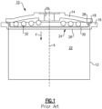
- a prior art molecular sieve unit 10 generally comprises a tubular-shaped bed housing 12 capped by an inlet end cap at a first end (not shown) and opposing outlet end cap 14 at a second end 16. Each end may be sealed with its respective end cap, such as through use of an O-ring seal 18. Each end cap may further include a respective inlet or outlet orifice, such as outlet orifice 20 of outlet end cap 14.
- a sieve bed 22 of adsorptive material e.g., zeolite
- a pressurized air flow of inlet air may enter molecular sieve unit 10 through the inlet orifice of the inlet end cap, pass through the adsorptive material of sieve bed 22 whereby a desired product gas may be output through outlet orifice 20 of outlet end cap 14.
- the adsorptive material is configured to selectively remove unwanted constituents (e.g., N 2 ) from an air supply so as to output a desired product gas (e.g., O 2 ).
- a bed retention system 24 may be positioned within housing 12 above bed 22 and be configured to cooperate with outlet end cap 14.
- Bed retention system 24 may include a felt filter and/or mesh screen (hereinafter, felt screen) 26 layered atop sieve bed 22, with a perforated plate 28 arranged to seat atop felt filter 26 along plate bottom face 30.
- Felt filter 26 may prevent adsorptive material from escaping from bed 22 by traveling through perforations within perforated plate 28.
- a conical spring 32 may be interposed between perforated plate 28 and outlet end cap 14 wherein conical spring 32 is biased to impart a downward force (indicated by arrow F) upon perforated plate 28 (toward the opposing inlet end cap) so as to maintain a compact sieve bed 22 within bed housing 12.
- a compact sieve bed 22 is desired as any gaps within the adsorptive material may provide a fluid path through which the pressurized inlet air may flow without undergoing gas separation.
- unwanted components may remain in the product gas, thereby reducing air separation efficiency and potentially producing hazardous or deadly product gases.
- packing a sieve bed 22 under too great a force may crush the adsorptive material, thereby reducing the number of, and availability to, active sights for gas separation on or within the adsorptive material (i.e., zeolite). Again, this situation may result in unwanted components remaining in the product gas.
- adsorptive material of sieve bed 22 may settle or compact over time, and in certain environments, a molecular sieve unit, such as unit 10, may be subject to extreme stresses, such as vibrations, particularly when installed within an OBOGS/OBIGGS unit of an aircraft, and more particularly when installed within a military aircraft.
- the adsorptive material i.e., zeolite
- molecular sieve unit 10 may include conical spring 32 configured to bias perforated plate 28 toward the inlet end cap while maintaining plate orientation and material containment.
- bed retention system 24 may fail.
- cracks and gaps may form which may decrease the air separation efficiency of the molecular sieve unit, potentially to an unsafe level.
- perforated plate 28 may tilt (i.e., no longer remain perpendicular to longitudinal axis A of bed housing 12) such that particulate adsorptive material of sieve bed 22 may be released from molecular sieve unit 10, such as through outlet orifice 20. Such a release would signal a catastrophic failure of molecular sieve unit 10.
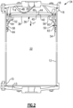
- a molecular sieve unit 34 in accordance with the present invention includes a housing 12 configured to receive a bed retention system 36. Similar to molecular sieve unit 10 described above, molecular sieve unit 34 may generally comprise a tubular-shaped bed housing 12 capped by an inlet end cap 13 at a first end 15 and opposing outlet end cap 14 at a second end 16. Each end may be sealed with its respective end cap, such as through use of an O-ring seal 18. Each end cap further includes a respective inlet or outlet orifice, such as outlet orifice 20 of outlet end cap 14.
- a sieve bed 22 of adsorptive material e.g., zeolite
- a prior art bed retention system 24 may be swapped with bed retention system 36 without requiring modification of housing 12 or either end cap.
- bed retention system 36 may include a felt filter 38 configured to be layered atop sieve bed 22, with a perforated plate 40 arranged to seat atop felt filter 38 along plate bottom face 42.
- Felt filter 38 may prevent adsorptive material from escaping from bed 22 by traveling through perforations within perforated plate 40.
- Washer 44 may be arranged atop plate top face 46 of perforated plate 40 and opposite felt filter 38.
- a biasing member, such as wave spring 48 may be interposed between perforated plate 40 (or washer 44, when included) and outlet end cap 14. Wave spring 48 is biased to impart a downward force (indicated by arrow F') upon perforated plate 40/ washer 44 toward the opposing inlet end cap so as to maintain a compact sieve bed 22 within bed housing 12.
- Skirt 50 is coupled to plate bottom face 42 by fasteners 52, such as but not limited to screws, bolts or rivets. Skirt 50 includes an open bottom end 54 and open top end 56 defining a side wall 58 therebetween. Inner surface 60 of side wall 58 is configured to form a cup-like shape while external surface 62 also includes one or more alignment components 64.
- alignment components 64 may include one or more O-rings.
- skirt 50 along with alignment component(s) 64 may be configured to assist maintaining a perpendicular orientation of perforated plate 40 relative to the walls of housing 12. Alignment component(s) 64 may further maintain an airtight seal between external surface 62 of skirt 50 and housing 12.
- inner surface 60 may operate to capture adsorptive material of sieve bed 22 at the outer circumference of sieve bed 22 and direct the adsorptive material towards the center of perforated plate 40. This movement may assist leveling of the absorptive material within sieve bed 22, keep the adsorptive material from clumping or cracking, as well as alleviate any forces which may cause rocking or tilting of perforated plate 40.
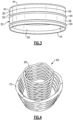
- wave spring 48 of bed retention system 36 may be replaced with wave spring assembly 66.
- Assembly 66 may incorporate first and second wave springs 68, 70 in which first wave spring 68 may be centrally located within second wave spring 70.
- This configuration may promote uniformity of spring force F' ( FIG. 2 ) applied to perforated plate 40 (and/or washer 44). The uniform spring force F' may then be applied to sieve bed 22, thereby further alleviating any potential rocking or tilting of perforated plate 40.
- any number of wave springs may be included within wave spring assembly 66, such as may be dictated by system requirements or housing capacities. It should be further appreciated that each of wave springs 48, 68, 70 may be manufactured from pre-hardened flat wire through an on-edge-coiling/edgewinding process. Moreover, while shown and described as wave springs, it should be appreciated by those skilled in the art that any suitable biasing member may be utilized, such as but not limited to coil springs or conical springs, and that such other and additional biasing members are to be considered within the scope of the present disclosure. With that being said, the exemplary wave spring 48 (or alternatively wave springs 68, 70) of molecular sieve unit 34 has less mass than corresponding conical or coil springs while also providing an increased free length for greater spring travel.
- sieve compaction 72 of a molecular sieve unit 34 in accordance with the present invention is compared with sieve compaction 74 of a prior art molecular sieve unit 10 as shown in FIG. 1 when subject to random vibrations typically experienced when such molecular sieve units may be deployed within a military aircraft. It should be noted that one minute of test time corresponds generally to one hour of unit flight time. It should be further noted that use of a wave spring/wave spring assembly extends the spring limit 76 compared to spring limit 78 of conical springs (spring limits indicate the point where the spring force is inadequate to maintain a compact sieve bed). As can be seen within FIG.
- prior art molecular sieve unit 10 has experienced sieve bed compaction greater than its spring limit at approximately 350 minutes of test time, thus indicating molecular sieve unit failure, as indicated at reference numeral 80.
- sieve compaction employing a bed retention system of the present invention such as bed retention system 36
- failure of molecular sieve unit 34 was avoided even after nearly 700 minutes of test time. Accordingly, failure of molecular sieve unit 34 due to vibrational compaction of sieve bed 22 may be greatly reduced, if not eliminated, when employing a bed retention system in accordance with the present invention.
Landscapes
- Chemical & Material Sciences (AREA)
- Engineering & Computer Science (AREA)
- Chemical Kinetics & Catalysis (AREA)
- Analytical Chemistry (AREA)
- General Chemical & Material Sciences (AREA)
- Oil, Petroleum & Natural Gas (AREA)
- Aviation & Aerospace Engineering (AREA)
- Inorganic Chemistry (AREA)
- Separation Of Gases By Adsorption (AREA)
- Solid-Sorbent Or Filter-Aiding Compositions (AREA)
- Combined Means For Separation Of Solids (AREA)
Description
- The present invention relates to molecular sieve devices, and more particularly to a molecular sieve retention system to contain and pack particulate material within a molecular sieve unit, and still more particularly to a molecular sieve retention system to contain and pack the particulate material within the molecular sieve unit even after the molecular sieve unit experiences extreme environmental conditions.
- Aircraft On-Board Oxygen Generation Systems/On-Board Inert Gas Generation Systems (OBOGS/OBIGGS) units are designed to separate gases from a pressurized air source in order to supply oxygen enriched air flow to the flight crew, while also supplying oxygen depleted air flow for inerting the fuel tank ullages. Such units typically employ molecular sieve gas separation processes, such as but not limited to pressure swing adsorption (PSA), wherein molecular sieve particulate material, such as a zeolite, is packed as a bed and retained within a molecular sieve unit. The sieve unit includes a housing, an inlet end cap, an outlet end cap and the sieve bed packed therein. A pressurized inlet gas may then enter through the inlet end cap, pass through the sieve bed wherein the inlet gas is separated by virtue of the sieve material such that unwanted components of the inlet air (e.g., N2) are selectively adsorbed by the sieve material while a desired product gas (e.g., O2) may pass through the sieve material and exit through the outlet end cap.
- To prevent unwanted movement of the particulate material of the sieve bed within the housing, traditional sieve housings include a plate and spring retention system where the spring provides a downward force upon the plate to maintain a compact bed. Such a force acts to inhibit the formation of gaps through which unwanted components of the inlet air may traverse the length of the housing rather than be adsorbed by the particulate material of the sieve bed. The challenge is to provide sufficient downward force upon the packed bed so that the sieve particles do not move relative to each other under severe application conditions while also avoiding force levels that crush the particles. The probability of achieving this condition is increased dramatically when the compaction force applied to the sieve bed is uniform across the cross sectional area that it is applied. With that in mind, previous sieve beds have utilized conical springs coupled to a perforated plate to provide the compaction force to spread the load to the packed bed. However, under extreme environmental conditions, the packed bed and its retention system may be subject to forces that can cause rocking and or tilting of the perforated plate, which can in turn result in movement of the packed bed and subsequent damage to the molecular sieve unit. The risk of this type of failure increases if there is even a slight misalignment of the perforated plate or spring during assembly.
- Therefore, a need remains for a molecular sieve retention system which can withstand the forces experienced due to extreme environmental conditions without risk of material bed damage and/or loss of sieve material retention.
FromUS 5,427,609 , a device for cleaning and drying compressed gas is known to include a filter with a plate on top, the plate having an axially downward extending flange. - The above problems are solved by the subject-matter of the independent claims.
- The present invention is generally directed to a retention system for use within a molecular sieve unit. The molecular sieve unit includes a housing sealed at a first end via an inlet end cap having an inlet orifice defined therein and at a second end via an outlet end cap having an outlet orifice defined therein. The housing is further configured to retain a packed sieve bed of adsorptive material. The retention system comprises a perforated plate having a top face and bottom face, wherein the perforated plate may be configured to be positioned atop the packed sieve bed proximate the outlet end cap; a skirt coupled to the bottom face of the perforated plate; and a biasing member configured to engage the outlet end cap and the top face of the perforated plate, wherein the biasing member urges the perforated plate against the packed sieve bed. The retention system may further comprise a felt filter and/or mesh screen configured to be interposed between the perforated plate and the packed sieve bed. At least a portion of the felt filter and/or mesh screen may also be interposed between the perforated plate and the skirt. In one aspect of the present invention, the biasing member may comprise a wave spring. In another aspect, the biasing member may comprise a wave spring assembly including two wave springs, wherein a first spring is centrally located within a second spring.
- The skirt further includes one or more alignment components configured to be interposed between the skirt and an internal wall of the housing. Each of the one or more alignment components may be an O-ring. An inner surface of the skirt is configured to direct the adsorptive material proximate the housing centrally inward toward a central axis of the housing.
- In another aspect of the present invention, a molecular sieve unit comprises a housing sealed at a first end via an inlet end cap having an inlet orifice defined therein and at a second end via an outlet end cap having an outlet orifice defined therein. A packed sieve bed of adsorptive material is disposed within the housing and a retention system is positioned between the packed sieve bed and the outlet end cap. The retention system comprises the features defined in claim 1.
- Additional objects, advantages and novel aspects of the present invention will be set forth in part in the description which follows, and will in part become apparent to those in the practice of the invention, when considered with the attached figures.
-
-
FIG. 1 is a cross section partial view of a prior art molecular sieve unit; -
FIG. 2 is a cross section partial view of a molecular sieve unit in accordance with an aspect of the present invention; -
FIG. 3 is an isolated view of a perforated plate and skirt that may be used within the molecular sieve unit shown inFIG. 2 ; -
FIG. 4 is a perspective view of a concentric spring apparatus that may be used within the molecular sieve unit shown inFIG. 2 ; and -
FIG. 5 is a graph depicting sieve compaction versus time during a vibration event comparing the prior art molecular sieve unit shown inFIG. 1 with the molecular sieve unit in accordance with the present invention as shown inFIG. 2 . - Referring now to
FIG. 1 a prior artmolecular sieve unit 10 generally comprises a tubular-shaped bed housing 12 capped by an inlet end cap at a first end (not shown) and opposingoutlet end cap 14 at asecond end 16. Each end may be sealed with its respective end cap, such as through use of an O-ring seal 18. Each end cap may further include a respective inlet or outlet orifice, such asoutlet orifice 20 ofoutlet end cap 14. Asieve bed 22 of adsorptive material (e.g., zeolite) may be located withinbed housing 12 between the inlet end cap andoutlet end cap 14. In this manner, a pressurized air flow of inlet air may entermolecular sieve unit 10 through the inlet orifice of the inlet end cap, pass through the adsorptive material ofsieve bed 22 whereby a desired product gas may be output throughoutlet orifice 20 ofoutlet end cap 14. In one aspect of the invention, the adsorptive material is configured to selectively remove unwanted constituents (e.g., N2) from an air supply so as to output a desired product gas (e.g., O2). - A
bed retention system 24 may be positioned withinhousing 12 abovebed 22 and be configured to cooperate withoutlet end cap 14.Bed retention system 24 may include a felt filter and/or mesh screen (hereinafter, felt screen) 26 layeredatop sieve bed 22, with aperforated plate 28 arranged to seat atop feltfilter 26 alongplate bottom face 30.Felt filter 26 may prevent adsorptive material from escaping frombed 22 by traveling through perforations withinperforated plate 28. Aconical spring 32 may be interposed betweenperforated plate 28 andoutlet end cap 14 whereinconical spring 32 is biased to impart a downward force (indicated by arrow F) upon perforated plate 28 (toward the opposing inlet end cap) so as to maintain acompact sieve bed 22 withinbed housing 12. Acompact sieve bed 22 is desired as any gaps within the adsorptive material may provide a fluid path through which the pressurized inlet air may flow without undergoing gas separation. As a result, unwanted components may remain in the product gas, thereby reducing air separation efficiency and potentially producing hazardous or deadly product gases. Conversely, packing asieve bed 22 under too great a force may crush the adsorptive material, thereby reducing the number of, and availability to, active sights for gas separation on or within the adsorptive material (i.e., zeolite). Again, this situation may result in unwanted components remaining in the product gas. - With continued reference to
FIG. 1 , adsorptive material ofsieve bed 22 may settle or compact over time, and in certain environments, a molecular sieve unit, such asunit 10, may be subject to extreme stresses, such as vibrations, particularly when installed within an OBOGS/OBIGGS unit of an aircraft, and more particularly when installed within a military aircraft. When subjected to such vibrations, the adsorptive material (i.e., zeolite) comprisingsieve bed 22 may become further compacted thereby creating cracks and gaps within the bed. To prevent cracks and gaps from forming,molecular sieve unit 10 may includeconical spring 32 configured to biasperforated plate 28 toward the inlet end cap while maintaining plate orientation and material containment. However, shouldsieve bed 22 continue to compact to such a degree that the spring force imparted byconical spring 32 is insufficient to maintain compaction of the bed viaperforated plate 28,bed retention system 24 may fail. In one instance, cracks and gaps may form which may decrease the air separation efficiency of the molecular sieve unit, potentially to an unsafe level. In a second instance,perforated plate 28 may tilt (i.e., no longer remain perpendicular to longitudinal axis A of bed housing 12) such that particulate adsorptive material ofsieve bed 22 may be released frommolecular sieve unit 10, such as throughoutlet orifice 20. Such a release would signal a catastrophic failure ofmolecular sieve unit 10. - Turning now to
FIG. 2 , amolecular sieve unit 34 in accordance with the present invention includes ahousing 12 configured to receive abed retention system 36. Similar tomolecular sieve unit 10 described above,molecular sieve unit 34 may generally comprise a tubular-shaped bed housing 12 capped by aninlet end cap 13 at afirst end 15 and opposingoutlet end cap 14 at asecond end 16. Each end may be sealed with its respective end cap, such as through use of an O-ring seal 18. Each end cap further includes a respective inlet or outlet orifice, such asoutlet orifice 20 ofoutlet end cap 14. Asieve bed 22 of adsorptive material (e.g., zeolite) is located withinbed housing 12 between the inlet end cap andoutlet end cap 14. In this manner, a prior artbed retention system 24 may be swapped withbed retention system 36 without requiring modification ofhousing 12 or either end cap. - As shown in
FIGS. 2 and3 ,bed retention system 36 may include a feltfilter 38 configured to be layered atopsieve bed 22, with aperforated plate 40 arranged to seat atopfelt filter 38 alongplate bottom face 42.Felt filter 38 may prevent adsorptive material from escaping frombed 22 by traveling through perforations withinperforated plate 40.Washer 44 may be arranged atop plate top face 46 ofperforated plate 40 andopposite felt filter 38. A biasing member, such aswave spring 48, may be interposed between perforated plate 40 (orwasher 44, when included) andoutlet end cap 14.Wave spring 48 is biased to impart a downward force (indicated by arrow F') uponperforated plate 40/washer 44 toward the opposing inlet end cap so as to maintain acompact sieve bed 22 withinbed housing 12. -
Skirt 50 is coupled to platebottom face 42 byfasteners 52, such as but not limited to screws, bolts or rivets.Skirt 50 includes an openbottom end 54 and opentop end 56 defining aside wall 58 therebetween.Inner surface 60 ofside wall 58 is configured to form a cup-like shape whileexternal surface 62 also includes one ormore alignment components 64. By way of example and without limitation thereto,alignment components 64 may include one or more O-rings. In accordance with an aspect of the present invention,skirt 50 along with alignment component(s) 64 may be configured to assist maintaining a perpendicular orientation ofperforated plate 40 relative to the walls ofhousing 12. Alignment component(s) 64 may further maintain an airtight seal betweenexternal surface 62 ofskirt 50 andhousing 12. Without subscribing to any particular theory of operation,inner surface 60 may operate to capture adsorptive material ofsieve bed 22 at the outer circumference ofsieve bed 22 and direct the adsorptive material towards the center ofperforated plate 40. This movement may assist leveling of the absorptive material withinsieve bed 22, keep the adsorptive material from clumping or cracking, as well as alleviate any forces which may cause rocking or tilting ofperforated plate 40. - In accordance with a further embodiment of the present invention, and as shown in
FIG. 4 ,wave spring 48 ofbed retention system 36 may be replaced withwave spring assembly 66.Assembly 66 may incorporate first and second wave springs 68, 70 in whichfirst wave spring 68 may be centrally located withinsecond wave spring 70. This configuration may promote uniformity of spring force F' (FIG. 2 ) applied to perforated plate 40 (and/or washer 44). The uniform spring force F' may then be applied tosieve bed 22, thereby further alleviating any potential rocking or tilting ofperforated plate 40. It should be understood by those skilled in the art that, while being shown and described as a pair of concentrically oriented wave springs, any number of wave springs may be included withinwave spring assembly 66, such as may be dictated by system requirements or housing capacities. It should be further appreciated that each of wave springs 48, 68, 70 may be manufactured from pre-hardened flat wire through an on-edge-coiling/edgewinding process. Moreover, while shown and described as wave springs, it should be appreciated by those skilled in the art that any suitable biasing member may be utilized, such as but not limited to coil springs or conical springs, and that such other and additional biasing members are to be considered within the scope of the present disclosure. With that being said, the exemplary wave spring 48 (or alternatively wave springs 68, 70) ofmolecular sieve unit 34 has less mass than corresponding conical or coil springs while also providing an increased free length for greater spring travel. - Turning now to
FIG. 5 ,sieve compaction 72 of amolecular sieve unit 34 in accordance with the present invention is compared withsieve compaction 74 of a prior artmolecular sieve unit 10 as shown inFIG. 1 when subject to random vibrations typically experienced when such molecular sieve units may be deployed within a military aircraft. It should be noted that one minute of test time corresponds generally to one hour of unit flight time. It should be further noted that use of a wave spring/wave spring assembly extends thespring limit 76 compared tospring limit 78 of conical springs (spring limits indicate the point where the spring force is inadequate to maintain a compact sieve bed). As can be seen withinFIG. 5 , prior artmolecular sieve unit 10 has experienced sieve bed compaction greater than its spring limit at approximately 350 minutes of test time, thus indicating molecular sieve unit failure, as indicated atreference numeral 80. In contrast, sieve compaction employing a bed retention system of the present invention, such asbed retention system 36, failure ofmolecular sieve unit 34 was avoided even after nearly 700 minutes of test time. Accordingly, failure ofmolecular sieve unit 34 due to vibrational compaction ofsieve bed 22 may be greatly reduced, if not eliminated, when employing a bed retention system in accordance with the present invention. - The foregoing description of the invention has been presented for the purpose of illustration and description. It is not intended to be exhaustive nor is it intended to limit the invention to the precise form(s) disclosed. It will be apparent to those skilled in the art that the disclosed embodiments may be modified in light of the above teachings. The embodiments described are chosen to provide an illustration of principles of the invention and its practical application to enable thereby one of ordinary skill in the art to utilize the invention in various embodiments and with various modifications as are suited to the particular use contemplated. Therefore, the foregoing description is to be considered exemplary, rather than limiting, and the true scope of the invention is that described in the following claims.
Claims (12)
- A retention system (36) for a molecular sieve unit (34), the molecular sieve unit (34) including a housing (12) sealed at a first end (15) via an inlet end cap (13) having an inlet orifice defined therein and at a second end (16) via an outlet end cap (14) having an outlet orifice (20) defined therein, the housing (12) configured to retain a packed sieve bed (22) of adsorptive material, the retention system (36) comprising:a. a perforated plate (40) having a top face (46) and bottom face (42), wherein the perforated plate (40) is configured to be positioned atop the packed sieve bed (22) proximate the outlet end cap (14);b. a skirt (50) coupled to the bottom face (42) of the perforated plate (40), the skirt (50) including a side wall (58) defined between an open bottom end (54) and an open top end (56) of the skirt (50), the side wall (58) having an inner surface (60) comprising a part which is, in a direction towards the open top end (56) of the skirt (50), curved towards a central axis of the housing (12) to form a cup-like shape such as to direct the adsorptive material proximate the housing (12) centrally inward toward the central axis of the housing (12), and an external surface (62) that includes one or more alignment components (64); andc. a biasing member (48; 66) configured to engage the outlet end cap (14) and the top face (46) of the perforated plate (40), wherein the biasing member (48;66) is configured to urge the perforated plate (40) against the packed sieve bed.
- The retention system (36) of claim 1 further comprising:
d. a felt filter (26) and/or mesh screen configured to be interposed between the perforated plate (40) and the packed sieve bed (22). - The retention system (36) of claim 2 wherein at least a portion of the felt filter (26) and/or mesh screen is interposed between the perforated plate (40) and the skirt (50).
- The retention system (36) of claim 1 or 3 wherein each of the one or more alignment components (64) is an O-ring.
- The retention system of claim 1 or 3 wherein the biasing member comprises a wave spring (68, 70).
- The retention system of claim 1 wherein the biasing member comprises a wave spring assembly (66) including two wave springs (68, 70), wherein a first spring (68) is centrally located within a second spring (70).
- A molecular sieve unit (34) comprising:a. a housing (12) sealed at a first end (15) via an inlet end cap (13) having an inlet orifice defined therein and at a second end (16) via an outlet end cap (14) having an outlet orifice (20) defined therein;b. a packed sieve bed (22) of adsorptive material disposed within the housing (12); andc. a retention system (36) positioned between the packed sieve bed (22) and the outlet end cap (14), the retention system (36) comprising:i. a perforated plate (40) having a top face (46) and bottom face (42), wherein the perforated plate (40) is positioned atop the packed sieve bed (22) proximate the outlet end cap (14);ii. a skirt (50) coupled to the bottom face (42) of the perforated plate (40), the skirt (50) including a side wall (58) defined between an open bottom end (54) and an open top end (56) of the skirt (50), the side wall (58) having an inner surface (60) comprising a part which is, in a direction towards the open top end (56) of the skirt (50), curved towards a central axis of the housing (12) to form a cup-like shape such as to direct the adsorptive material proximate the housing (12) centrally inward toward the central axis of the housing (12), and an external surface (62) that includes one or more alignment components (64); andiii. a biasing member (48; 66) configured to engage the outlet end cap (14) and the top face (46) of the perforated plate (40), wherein the biasing member (48; 66) urges the perforated plate (40) against the packed sieve bed (22).
- The molecular sieve unit (34) of claim 7 wherein the retention system further comprises:
iv. a felt filter (26) and/or mesh screen interposed between the perforated plate (40) and the packed sieve bed (22). - The molecular sieve unit (34) of claim 8 wherein at least a portion of the felt filter (26) and/or mesh screen is interposed between the perforated plate (40) and the skirt (50).
- The molecular sieve unit (34) of claim 9 wherein each of the one or more alignment components (64) is an O-ring.
- The molecular sieve unit (34) of claim 7 wherein the biasing member comprises a wave spring (68,70).
- The molecular sieve unit of claim 7 wherein the biasing member comprises two wave springs (68, 70), wherein a first spring (68) is centrally located within a second spring (70).
Applications Claiming Priority (2)
| Application Number | Priority Date | Filing Date | Title |
|---|---|---|---|
| US201662320976P | 2016-04-11 | 2016-04-11 | |
| PCT/US2017/026784 WO2017180508A1 (en) | 2016-04-11 | 2017-04-10 | Sieve bed retention system |
Publications (3)
| Publication Number | Publication Date |
|---|---|
| EP3442690A1 EP3442690A1 (en) | 2019-02-20 |
| EP3442690A4 EP3442690A4 (en) | 2019-12-11 |
| EP3442690B1 true EP3442690B1 (en) | 2025-01-15 |
Family
ID=59999921
Family Applications (1)
| Application Number | Title | Priority Date | Filing Date |
|---|---|---|---|
| EP17782912.4A Active EP3442690B1 (en) | 2016-04-11 | 2017-04-10 | Sieve bed retention system |
Country Status (6)
| Country | Link |
|---|---|
| US (1) | US10273005B2 (en) |
| EP (1) | EP3442690B1 (en) |
| JP (1) | JP7091590B2 (en) |
| KR (1) | KR102212620B1 (en) |
| CA (1) | CA3020723C (en) |
| WO (1) | WO2017180508A1 (en) |
Families Citing this family (5)
| Publication number | Priority date | Publication date | Assignee | Title |
|---|---|---|---|---|
| CN116648278A (en) | 2020-07-16 | 2023-08-25 | 英瓦卡尔公司 | Systems and methods for enriching gases |
| CN116075352A (en) | 2020-07-16 | 2023-05-05 | 英瓦卡尔公司 | Systems and methods for enriching gases |
| WO2022015904A1 (en) * | 2020-07-16 | 2022-01-20 | Invacare Corporation | System and methods for concentrating gas |
| WO2022015907A1 (en) | 2020-07-16 | 2022-01-20 | Invacare Corporation | System and method for concentrating gas |
| US12347555B2 (en) | 2021-07-15 | 2025-07-01 | Ventec Life Systems, Inc. | System and method for medical device communication |
Family Cites Families (30)
| Publication number | Priority date | Publication date | Assignee | Title |
|---|---|---|---|---|
| US3815752A (en) * | 1972-03-02 | 1974-06-11 | Sporlan Valve Co | Refrigerant filter-drier |
| US4636315A (en) * | 1982-12-09 | 1987-01-13 | Research Triangle Institute | Fluid separator apparatus and method |
| GB8528249D0 (en) | 1985-11-15 | 1985-12-18 | Normalair Garrett Ltd | Molecular sieve bed containers |
| JPS6295166U (en) * | 1985-12-04 | 1987-06-17 | ||
| US4826510A (en) | 1988-01-13 | 1989-05-02 | The John Bunn Company | Portable low profile DC oxygen concentrator |
| US5275642A (en) | 1989-05-17 | 1994-01-04 | Stuart Bassine | Molecular sieve for oxygen concentrator |
| JP3213024B2 (en) * | 1991-10-08 | 2001-09-25 | 株式会社リキッドガス | Gas purification equipment |
| US5427609A (en) * | 1993-09-14 | 1995-06-27 | Horton Industries, Inc. | Device for cleaning and drying compressed gas |
| GB9412856D0 (en) * | 1994-06-27 | 1994-08-17 | Normalair Garrett Ltd | Canister for inorganic sorbent particles |
| US5531807A (en) | 1994-11-30 | 1996-07-02 | Airsep Corporation | Apparatus and method for supplying oxygen to passengers on board aircraft |
| US5482261A (en) * | 1995-02-15 | 1996-01-09 | Automatic Spring Coiling Co. | Nested spring assembly |
| SE9800843L (en) * | 1998-03-16 | 1999-09-17 | Haldex Brake Prod Ab | Dryer |
| US6334889B1 (en) * | 1999-09-01 | 2002-01-01 | Praxair Technology, Inc. | Bed restraint for an adsorber |
| US6517598B2 (en) * | 2001-06-06 | 2003-02-11 | Donaldson Company, Inc. | Filter element having flange and methods |
| US6681807B1 (en) | 2002-07-15 | 2004-01-27 | Litton Systems, Inc. | Asymmetric bidirectional flow device |
| US6730143B1 (en) | 2002-11-18 | 2004-05-04 | Bendix Commercial Vehicle Systems, Llc | Truck air dryer purge air cleaner |
| US7135059B2 (en) | 2003-10-07 | 2006-11-14 | Inogen, Inc. | Portable gas fractionalization system |
| US7066985B2 (en) | 2003-10-07 | 2006-06-27 | Inogen, Inc. | Portable gas fractionalization system |
| US7438745B2 (en) | 2003-10-07 | 2008-10-21 | Inogen, Inc. | Portable gas fractionalization system |
| GB0327582D0 (en) | 2003-11-27 | 2003-12-31 | Madison Filter 981 Ltd | Filter cloth retention |
| EP1986763A4 (en) | 2006-01-30 | 2009-12-23 | Advanced Tech Materials | Nanoporous carbon materials, and systems and methods utilizing same |
| JP4937949B2 (en) | 2008-03-19 | 2012-05-23 | 愛三工業株式会社 | Evaporative fuel processing equipment |
| US7909919B2 (en) * | 2008-03-10 | 2011-03-22 | Aisan Kogyo Kabushiki Kaisha | Vaporized fuel treatment apparatus |
| DE102009030897B4 (en) * | 2009-06-29 | 2015-02-26 | Knorr-Bremse Systeme für Nutzfahrzeuge GmbH | Air dryer cartridge for a compressed air treatment plant of a vehicle and compressed air treatment plant for a vehicle with a corresponding air dryer cartridge. |
| US8257473B2 (en) * | 2010-07-08 | 2012-09-04 | Airsep Corporation | Sieve bed |
| DE102011054329A1 (en) * | 2011-10-10 | 2013-04-11 | Haldex Brake Products Gmbh | Air drying cartridge |
| US9089801B1 (en) * | 2011-11-08 | 2015-07-28 | Denali Medical Concepts, Llc | Manifold and strainer assembly |
| IL226357A (en) | 2013-05-13 | 2017-06-29 | Beth El Zikhron Yaaqov Ind Ltd | Filter assembly for nuclear, biological and chemical (nbc) air filtration system and method of manufacture thereof |
| FR3011484B1 (en) * | 2013-10-09 | 2017-06-23 | Air Liquide | AIR SEPARATION DEVICE, INERTING DEVICE AND AIRCRAFT COMPRISING SUCH A DEVICE |
| KR102380037B1 (en) | 2014-09-30 | 2022-03-28 | 미쓰비시 마테리알 가부시키가이샤 | SUBSTRATE FOR POWER MODULE WITH Ag UNDERLAYER AND POWER MODULE |
-
2017
- 2017-04-10 EP EP17782912.4A patent/EP3442690B1/en active Active
- 2017-04-10 JP JP2018553431A patent/JP7091590B2/en active Active
- 2017-04-10 CA CA3020723A patent/CA3020723C/en active Active
- 2017-04-10 WO PCT/US2017/026784 patent/WO2017180508A1/en not_active Ceased
- 2017-04-10 KR KR1020187032574A patent/KR102212620B1/en active Active
- 2017-04-10 US US15/483,200 patent/US10273005B2/en active Active
Also Published As
| Publication number | Publication date |
|---|---|
| JP2019513551A (en) | 2019-05-30 |
| KR20190006493A (en) | 2019-01-18 |
| CA3020723C (en) | 2024-02-20 |
| EP3442690A1 (en) | 2019-02-20 |
| JP7091590B2 (en) | 2022-06-28 |
| WO2017180508A1 (en) | 2017-10-19 |
| US20170291708A1 (en) | 2017-10-12 |
| EP3442690A4 (en) | 2019-12-11 |
| KR102212620B1 (en) | 2021-02-04 |
| US10273005B2 (en) | 2019-04-30 |
| CA3020723A1 (en) | 2017-10-19 |
Similar Documents
| Publication | Publication Date | Title |
|---|---|---|
| US10273005B2 (en) | Sieve bed retention system | |
| US9328700B2 (en) | Fuel vapor processing apparatus | |
| JP5600621B2 (en) | Evaporative fuel processing equipment | |
| US5520807A (en) | Stacked fluid-separation membrane disk module assemblies | |
| JP5976381B2 (en) | Evaporative fuel processing equipment | |
| CN104147861B (en) | Filter assemblies and its manufacturing method for core, biological and chemical air filtering system | |
| JP6430495B2 (en) | Air separation device, deactivation device, and aircraft equipped with such a device | |
| US10252212B2 (en) | Moisture resistant molecular sieve beds | |
| US10130910B2 (en) | Compressed air drying device | |
| JP2011255295A (en) | Filter and oil-water separator | |
| IES87358Y1 (en) | Filter element for separating oil vapor from a gas flow | |
| US9249762B2 (en) | Evaporated fuel treatment apparatus | |
| US9587594B2 (en) | Evaporated fuel processing apparatus | |
| JP6481030B2 (en) | Fuel cap | |
| Bhat et al. | On-board oxygen generation using high performance molecular sieve | |
| CN207478535U (en) | Solid particle material feeding tank and gas-solid phase reaction device | |
| US9120048B2 (en) | Adsorber with horizontal axial bed and clearing system of packing | |
| US11679355B2 (en) | Adsorber for purifying or separating a gas stream comprising a removable filling system | |
| US20200282359A1 (en) | System and method for microjet and vibration-assisted fluidization of nanoparticles | |
| US20250020093A1 (en) | Evaporated fuel treatment device and manufacturing method of evaporated fuel treatment device | |
| JP2019124171A (en) | Evaporated fuel treatment device | |
| US10071336B1 (en) | Gas purification getter construction for airborne and space applications | |
| US20180141024A1 (en) | Molded Adsorbents and Canisters Containing the Molded Adsorbents | |
| RU2778060C2 (en) | Adsorber for purification or separation of gas flow, containing removable filling system | |
| JPH0444840Y2 (en) |
Legal Events
| Date | Code | Title | Description |
|---|---|---|---|
| STAA | Information on the status of an ep patent application or granted ep patent |
Free format text: STATUS: THE INTERNATIONAL PUBLICATION HAS BEEN MADE |
|
| PUAI | Public reference made under article 153(3) epc to a published international application that has entered the european phase |
Free format text: ORIGINAL CODE: 0009012 |
|
| STAA | Information on the status of an ep patent application or granted ep patent |
Free format text: STATUS: REQUEST FOR EXAMINATION WAS MADE |
|
| 17P | Request for examination filed |
Effective date: 20181108 |
|
| AK | Designated contracting states |
Kind code of ref document: A1 Designated state(s): AL AT BE BG CH CY CZ DE DK EE ES FI FR GB GR HR HU IE IS IT LI LT LU LV MC MK MT NL NO PL PT RO RS SE SI SK SM TR |
|
| AX | Request for extension of the european patent |
Extension state: BA ME |
|
| DAV | Request for validation of the european patent (deleted) | ||
| DAX | Request for extension of the european patent (deleted) | ||
| RIN1 | Information on inventor provided before grant (corrected) |
Inventor name: BUENTING, TODD Inventor name: DICKEN, LANE Inventor name: WEBER, JUSTIN |
|
| REG | Reference to a national code |
Ref country code: DE Ref legal event code: R079 Free format text: PREVIOUS MAIN CLASS: B01D0071020000 Ipc: B01D0053040000 |
|
| A4 | Supplementary search report drawn up and despatched |
Effective date: 20191112 |
|
| RIC1 | Information provided on ipc code assigned before grant |
Ipc: B64D 37/32 20060101ALI20191106BHEP Ipc: B01D 53/04 20060101AFI20191106BHEP |
|
| RAP1 | Party data changed (applicant data changed or rights of an application transferred) |
Owner name: COBHAM MISSION SYSTEMS DAVENPORT LLS INC. |
|
| RAP1 | Party data changed (applicant data changed or rights of an application transferred) |
Owner name: COBHAM MISSION SYSTEMS DAVENPORT LSS INC. |
|
| STAA | Information on the status of an ep patent application or granted ep patent |
Free format text: STATUS: EXAMINATION IS IN PROGRESS |
|
| 17Q | First examination report despatched |
Effective date: 20210901 |
|
| P01 | Opt-out of the competence of the unified patent court (upc) registered |
Effective date: 20230521 |
|
| GRAP | Despatch of communication of intention to grant a patent |
Free format text: ORIGINAL CODE: EPIDOSNIGR1 |
|
| STAA | Information on the status of an ep patent application or granted ep patent |
Free format text: STATUS: GRANT OF PATENT IS INTENDED |
|
| INTG | Intention to grant announced |
Effective date: 20240807 |
|
| GRAS | Grant fee paid |
Free format text: ORIGINAL CODE: EPIDOSNIGR3 |
|
| GRAA | (expected) grant |
Free format text: ORIGINAL CODE: 0009210 |
|
| STAA | Information on the status of an ep patent application or granted ep patent |
Free format text: STATUS: THE PATENT HAS BEEN GRANTED |
|
| AK | Designated contracting states |
Kind code of ref document: B1 Designated state(s): AL AT BE BG CH CY CZ DE DK EE ES FI FR GB GR HR HU IE IS IT LI LT LU LV MC MK MT NL NO PL PT RO RS SE SI SK SM TR |
|
| REG | Reference to a national code |
Ref country code: CH Ref legal event code: EP Ref country code: GB Ref legal event code: FG4D |
|
| REG | Reference to a national code |
Ref country code: DE Ref legal event code: R096 Ref document number: 602017087360 Country of ref document: DE |
|
| REG | Reference to a national code |
Ref country code: IE Ref legal event code: FG4D |
|
| REG | Reference to a national code |
Ref country code: NL Ref legal event code: MP Effective date: 20250115 |
|
| PG25 | Lapsed in a contracting state [announced via postgrant information from national office to epo] |
Ref country code: NL Free format text: LAPSE BECAUSE OF FAILURE TO SUBMIT A TRANSLATION OF THE DESCRIPTION OR TO PAY THE FEE WITHIN THE PRESCRIBED TIME-LIMIT Effective date: 20250115 |
|
| PG25 | Lapsed in a contracting state [announced via postgrant information from national office to epo] |
Ref country code: RS Free format text: LAPSE BECAUSE OF FAILURE TO SUBMIT A TRANSLATION OF THE DESCRIPTION OR TO PAY THE FEE WITHIN THE PRESCRIBED TIME-LIMIT Effective date: 20250415 |
|
| PG25 | Lapsed in a contracting state [announced via postgrant information from national office to epo] |
Ref country code: FI Free format text: LAPSE BECAUSE OF FAILURE TO SUBMIT A TRANSLATION OF THE DESCRIPTION OR TO PAY THE FEE WITHIN THE PRESCRIBED TIME-LIMIT Effective date: 20250115 |
|
| PG25 | Lapsed in a contracting state [announced via postgrant information from national office to epo] |
Ref country code: PL Free format text: LAPSE BECAUSE OF FAILURE TO SUBMIT A TRANSLATION OF THE DESCRIPTION OR TO PAY THE FEE WITHIN THE PRESCRIBED TIME-LIMIT Effective date: 20250115 |
|
| PGFP | Annual fee paid to national office [announced via postgrant information from national office to epo] |
Ref country code: DE Payment date: 20250429 Year of fee payment: 9 |
|
| PG25 | Lapsed in a contracting state [announced via postgrant information from national office to epo] |
Ref country code: ES Free format text: LAPSE BECAUSE OF FAILURE TO SUBMIT A TRANSLATION OF THE DESCRIPTION OR TO PAY THE FEE WITHIN THE PRESCRIBED TIME-LIMIT Effective date: 20250115 |
|
| PGFP | Annual fee paid to national office [announced via postgrant information from national office to epo] |
Ref country code: GB Payment date: 20250428 Year of fee payment: 9 |
|
| REG | Reference to a national code |
Ref country code: LT Ref legal event code: MG9D |
|
| PG25 | Lapsed in a contracting state [announced via postgrant information from national office to epo] |
Ref country code: NO Free format text: LAPSE BECAUSE OF FAILURE TO SUBMIT A TRANSLATION OF THE DESCRIPTION OR TO PAY THE FEE WITHIN THE PRESCRIBED TIME-LIMIT Effective date: 20250415 Ref country code: IS Free format text: LAPSE BECAUSE OF FAILURE TO SUBMIT A TRANSLATION OF THE DESCRIPTION OR TO PAY THE FEE WITHIN THE PRESCRIBED TIME-LIMIT Effective date: 20250515 |
|
| REG | Reference to a national code |
Ref country code: AT Ref legal event code: MK05 Ref document number: 1759480 Country of ref document: AT Kind code of ref document: T Effective date: 20250115 |
|
| PG25 | Lapsed in a contracting state [announced via postgrant information from national office to epo] |
Ref country code: HR Free format text: LAPSE BECAUSE OF FAILURE TO SUBMIT A TRANSLATION OF THE DESCRIPTION OR TO PAY THE FEE WITHIN THE PRESCRIBED TIME-LIMIT Effective date: 20250115 |
|
| PG25 | Lapsed in a contracting state [announced via postgrant information from national office to epo] |
Ref country code: LV Free format text: LAPSE BECAUSE OF FAILURE TO SUBMIT A TRANSLATION OF THE DESCRIPTION OR TO PAY THE FEE WITHIN THE PRESCRIBED TIME-LIMIT Effective date: 20250115 Ref country code: PT Free format text: LAPSE BECAUSE OF FAILURE TO SUBMIT A TRANSLATION OF THE DESCRIPTION OR TO PAY THE FEE WITHIN THE PRESCRIBED TIME-LIMIT Effective date: 20250515 |
|
| PGFP | Annual fee paid to national office [announced via postgrant information from national office to epo] |
Ref country code: FR Payment date: 20250425 Year of fee payment: 9 |
|
| PG25 | Lapsed in a contracting state [announced via postgrant information from national office to epo] |
Ref country code: BG Free format text: LAPSE BECAUSE OF FAILURE TO SUBMIT A TRANSLATION OF THE DESCRIPTION OR TO PAY THE FEE WITHIN THE PRESCRIBED TIME-LIMIT Effective date: 20250115 Ref country code: GR Free format text: LAPSE BECAUSE OF FAILURE TO SUBMIT A TRANSLATION OF THE DESCRIPTION OR TO PAY THE FEE WITHIN THE PRESCRIBED TIME-LIMIT Effective date: 20250416 |
|
| PG25 | Lapsed in a contracting state [announced via postgrant information from national office to epo] |
Ref country code: AT Free format text: LAPSE BECAUSE OF FAILURE TO SUBMIT A TRANSLATION OF THE DESCRIPTION OR TO PAY THE FEE WITHIN THE PRESCRIBED TIME-LIMIT Effective date: 20250115 |
|
| PG25 | Lapsed in a contracting state [announced via postgrant information from national office to epo] |
Ref country code: SE Free format text: LAPSE BECAUSE OF FAILURE TO SUBMIT A TRANSLATION OF THE DESCRIPTION OR TO PAY THE FEE WITHIN THE PRESCRIBED TIME-LIMIT Effective date: 20250115 |
|
| PG25 | Lapsed in a contracting state [announced via postgrant information from national office to epo] |
Ref country code: SM Free format text: LAPSE BECAUSE OF FAILURE TO SUBMIT A TRANSLATION OF THE DESCRIPTION OR TO PAY THE FEE WITHIN THE PRESCRIBED TIME-LIMIT Effective date: 20250115 |
|
| PG25 | Lapsed in a contracting state [announced via postgrant information from national office to epo] |
Ref country code: DK Free format text: LAPSE BECAUSE OF FAILURE TO SUBMIT A TRANSLATION OF THE DESCRIPTION OR TO PAY THE FEE WITHIN THE PRESCRIBED TIME-LIMIT Effective date: 20250115 |
|
| PG25 | Lapsed in a contracting state [announced via postgrant information from national office to epo] |
Ref country code: IT Free format text: LAPSE BECAUSE OF FAILURE TO SUBMIT A TRANSLATION OF THE DESCRIPTION OR TO PAY THE FEE WITHIN THE PRESCRIBED TIME-LIMIT Effective date: 20250115 |
|
| REG | Reference to a national code |
Ref country code: DE Ref legal event code: R097 Ref document number: 602017087360 Country of ref document: DE |
|
| PG25 | Lapsed in a contracting state [announced via postgrant information from national office to epo] |
Ref country code: EE Free format text: LAPSE BECAUSE OF FAILURE TO SUBMIT A TRANSLATION OF THE DESCRIPTION OR TO PAY THE FEE WITHIN THE PRESCRIBED TIME-LIMIT Effective date: 20250115 Ref country code: CZ Free format text: LAPSE BECAUSE OF FAILURE TO SUBMIT A TRANSLATION OF THE DESCRIPTION OR TO PAY THE FEE WITHIN THE PRESCRIBED TIME-LIMIT Effective date: 20250115 |
|
| PG25 | Lapsed in a contracting state [announced via postgrant information from national office to epo] |
Ref country code: RO Free format text: LAPSE BECAUSE OF FAILURE TO SUBMIT A TRANSLATION OF THE DESCRIPTION OR TO PAY THE FEE WITHIN THE PRESCRIBED TIME-LIMIT Effective date: 20250115 |
|
| PG25 | Lapsed in a contracting state [announced via postgrant information from national office to epo] |
Ref country code: SK Free format text: LAPSE BECAUSE OF FAILURE TO SUBMIT A TRANSLATION OF THE DESCRIPTION OR TO PAY THE FEE WITHIN THE PRESCRIBED TIME-LIMIT Effective date: 20250115 |
|
| PLBE | No opposition filed within time limit |
Free format text: ORIGINAL CODE: 0009261 |
|
| STAA | Information on the status of an ep patent application or granted ep patent |
Free format text: STATUS: NO OPPOSITION FILED WITHIN TIME LIMIT |
|
| REG | Reference to a national code |
Ref country code: CH Ref legal event code: H13 Free format text: ST27 STATUS EVENT CODE: U-0-0-H10-H13 (AS PROVIDED BY THE NATIONAL OFFICE) Effective date: 20251125 |
|
| REG | Reference to a national code |
Ref country code: CH Ref legal event code: L10 Free format text: ST27 STATUS EVENT CODE: U-0-0-L10-L00 (AS PROVIDED BY THE NATIONAL OFFICE) Effective date: 20251126 |
|
| PG25 | Lapsed in a contracting state [announced via postgrant information from national office to epo] |
Ref country code: LU Free format text: LAPSE BECAUSE OF NON-PAYMENT OF DUE FEES Effective date: 20250410 |
|
| PG25 | Lapsed in a contracting state [announced via postgrant information from national office to epo] |
Ref country code: MC Free format text: LAPSE BECAUSE OF FAILURE TO SUBMIT A TRANSLATION OF THE DESCRIPTION OR TO PAY THE FEE WITHIN THE PRESCRIBED TIME-LIMIT Effective date: 20250115 |
|
| 26N | No opposition filed |
Effective date: 20251016 |
|
| REG | Reference to a national code |
Ref country code: BE Ref legal event code: MM Effective date: 20250430 |
|
| PG25 | Lapsed in a contracting state [announced via postgrant information from national office to epo] |
Ref country code: BE Free format text: LAPSE BECAUSE OF NON-PAYMENT OF DUE FEES Effective date: 20250430 |
|
| PG25 | Lapsed in a contracting state [announced via postgrant information from national office to epo] |
Ref country code: CH Free format text: LAPSE BECAUSE OF NON-PAYMENT OF DUE FEES Effective date: 20250430 |
|
| PG25 | Lapsed in a contracting state [announced via postgrant information from national office to epo] |
Ref country code: IE Free format text: LAPSE BECAUSE OF NON-PAYMENT OF DUE FEES Effective date: 20250410 |