EP3442669B1 - Weight bearing fall protection connector having a wireless fall indicator - Google Patents
Weight bearing fall protection connector having a wireless fall indicator Download PDFInfo
- Publication number
- EP3442669B1 EP3442669B1 EP16898807.9A EP16898807A EP3442669B1 EP 3442669 B1 EP3442669 B1 EP 3442669B1 EP 16898807 A EP16898807 A EP 16898807A EP 3442669 B1 EP3442669 B1 EP 3442669B1
- Authority
- EP
- European Patent Office
- Prior art keywords
- fall
- connector
- collar
- fall protection
- bar
- Prior art date
- Legal status (The legal status is an assumption and is not a legal conclusion. Google has not performed a legal analysis and makes no representation as to the accuracy of the status listed.)
- Active
Links
Images



Classifications
-
- A—HUMAN NECESSITIES
- A62—LIFE-SAVING; FIRE-FIGHTING
- A62B—DEVICES, APPARATUS OR METHODS FOR LIFE-SAVING
- A62B35/00—Safety belts or body harnesses; Similar equipment for limiting displacement of the human body, especially in case of sudden changes of motion
-
- A—HUMAN NECESSITIES
- A62—LIFE-SAVING; FIRE-FIGHTING
- A62B—DEVICES, APPARATUS OR METHODS FOR LIFE-SAVING
- A62B35/00—Safety belts or body harnesses; Similar equipment for limiting displacement of the human body, especially in case of sudden changes of motion
- A62B35/0006—Harnesses; Accessories therefor
- A62B35/0025—Details and accessories
- A62B35/0037—Attachments for lifelines and lanyards
-
- F—MECHANICAL ENGINEERING; LIGHTING; HEATING; WEAPONS; BLASTING
- F16—ENGINEERING ELEMENTS AND UNITS; GENERAL MEASURES FOR PRODUCING AND MAINTAINING EFFECTIVE FUNCTIONING OF MACHINES OR INSTALLATIONS; THERMAL INSULATION IN GENERAL
- F16B—DEVICES FOR FASTENING OR SECURING CONSTRUCTIONAL ELEMENTS OR MACHINE PARTS TOGETHER, e.g. NAILS, BOLTS, CIRCLIPS, CLAMPS, CLIPS OR WEDGES; JOINTS OR JOINTING
- F16B45/00—Hooks; Eyes
- F16B45/02—Hooks with pivoting or elastically bending closing member
- F16B45/023—Hooks with pivoting or elastically bending closing member the closing member pivoting about an axis perpendicular to the plane of the hook
-
- F—MECHANICAL ENGINEERING; LIGHTING; HEATING; WEAPONS; BLASTING
- F16—ENGINEERING ELEMENTS AND UNITS; GENERAL MEASURES FOR PRODUCING AND MAINTAINING EFFECTIVE FUNCTIONING OF MACHINES OR INSTALLATIONS; THERMAL INSULATION IN GENERAL
- F16B—DEVICES FOR FASTENING OR SECURING CONSTRUCTIONAL ELEMENTS OR MACHINE PARTS TOGETHER, e.g. NAILS, BOLTS, CIRCLIPS, CLAMPS, CLIPS OR WEDGES; JOINTS OR JOINTING
- F16B45/00—Hooks; Eyes
- F16B45/02—Hooks with pivoting or elastically bending closing member
- F16B45/027—Hooks with pivoting or elastically bending closing member and having position-locking means for the closing member
- F16B45/028—Hooks with pivoting or elastically bending closing member and having position-locking means for the closing member the position-locking means being pivotally connected
Definitions
- This invention relates to fall protection systems and equipment, and more particularly, to weight bearing couplings/connectors that are used to connect various pieces of fall protection equipment and to transfer the weight of a worker from one piece of fall protection equipment to another during a fall event.
- fall protection systems typically consist of a fall harness worn by the worker and connected to a static line or self-retracting lifeline (SRL). Together such systems provide a reliable restraint system worn by the worker that is connected to a fixed anchor point on a supporting structure.
- SRL self-retracting lifeline
- Such fall protection systems are designed to arrest the fall of a worker quickly and safely, but result in the worker being suspended in the fall harness. If there is no ladder or scaffolding for the worker to climb back up, the worker will remain suspended until additional rescue help can be rendered.
- the fall harness and safety/lifeline are designed to absorb the impact of the fall, which typically results in damage to the fall protection equipment.
- Various indicators are used on fall harnesses, fall lanyards and SRL's to indicate this damage.
- the coupling/connector used between the fall harness and the static safety line, fall lanyard, or SRL often includes a visual fall indicator.
- One such fall indicator consists of a sliding bar that is held in place with a metal pin. When a fall occurs, the sliding bar will sever the metal pin and move to position where a red fall indicator on the bar is exposed.
- AU 2006207863 (A1 ) discloses a fall notifying apparatus adapted for deployment across a shock adsorbing portion of a lanyard, comprising first and second base members adapted to move apart relative to one another when subjected to a tensile force resulting from a fall; at least one tensile member coupled to the first and second base members, the tensile member adapted to prevent the first and second base members from moving apart in the absence of the first and second base members being subjected to a tensile force resulting from a fall; coupling means for coupling the fall notifying apparatus across the shock absorbing portion of the lanyard; a detector for detecting when the first and second base members have moved apart from one another; and notification means for notifying a fall in response to detection of separation of the first and second base members from one another.
- US 2010/326767 discloses a swivel D-ring attachment point.
- a first attachment portion has a first closed aperture defining a circular ring portion that extends over a first circumferential range of at least 180 degrees of arc that is symmetrically disposed relative to an axis.
- a second attachment portion has a second closed aperture. The first and second attachment portions are joined together so as to permit freely swivelling one of the attachment portions relative to the other around the axis.
- the second aperture has a shape that is substantially different from the shape of the first aperture, for connecting to substantially different articles.
- GB 2486012 (A ) discloses an alarm device for a fall protection system, the alarm device comprising a first connector for connecting the device to a safety harness and a second connector for connecting the device to a safety line, the device thereby being connected, in use, in series between the harness and the safety line, wherein the device includes load monitoring means for monitoring the load between the connectors, and hence the load on the safety line, and for triggering an alarm 6 if the load exceeds a threshold.
- the load monitoring means 30 maybe an electrical load cell having a strain gauge.
- FR 2 755 236 A1 discloses a sensor connected between a safety harness and an anchoring point using upper and lower rings.
- the lower ring has a rod held stationary within a head by a flange which contains a contactor and operating button.
- the upper ring also has a rod which passes through a head and is connected to a piston normally held against the operating button by a spring. Under extreme tension the piston moves releasing the button and operating the contactor to produce a radio alarm.
- Mechanical strength is provided by a steel cylinder.
- US 5,220,977 discloses a fall indicating device including an indicating portion that is normally retained within the body of the fall indicator Upon the exertion of sufficient force upon the fall indicator, as, for example, from the forces generated during fall arrest, a restraining member within the body of the fall indicator, such as a shear pin or a series of disk springs, releases the indicating portion, alerting the user that the fall restraining device has been subjected to fall arrest forces.
- a restraining member within the body of the fall indicator such as a shear pin or a series of disk springs
- the indicator may require replacement after being subjected to fall arrest forces.
- a fall indicator using a spring or series of disk springs may be reset after use without needing to be replaced.
- a weight bearing fall protection connector for connecting one piece of fall protection equipment to another piece of fall protection equipment to transfer the weight of a worker in the event of a fall, comprising: a first connection member configured to attach the connector to one piece of fall protection equipment and having a first weight transfer portion, wherein the first weight transfer portion comprises a bar and a first collar, wherein the first collar is connected to the bar at the opposite end of the end at which the one piece of fall protection equipment is to be attached, and wherein the first collar defines a first stop surface; a second connection member configured to attach the connector to another piece of fall protection equipment and having a second weight transfer portion, the second weight transfer portion comprising an opening, configured to receive the bar for sliding and rotational movement of the bar in the opening, and a second collar, wherein the second collar is positioned on the bar between the first collar and the opening, wherein the second collar defines a second stop surface facing the first stop surface, and wherein the first and second connection members have a ready position where
- the first connection member comprises a first connection portion to attach the first connection member to one piece of fall protection equipment; and the second connection member comprises a second connection portion to attach the second connection member to another piece of fall protection equipment.
- the bar is a cylindrical shaft and the opening is a cylindrical bore that allow the connection members to swivel relative to each other in the ready position.
- connection members or the shear pin is configured to generate a magnetic field
- the switch is a magnetic reed switch that is actuated in response to movement of the magnetic field as the connection members move from the ready position to the fall position.
- the connector is a D-ring connector.
- the connector is a Snap Hook connector.
- This invention enables the fall protection system to automatically and immediately notify responsible persons of the fall event. This reduces the response time and the time the person is suspended in the fall equipment.
- a weight bearing fall protection coupling/connector 10 is provided for connecting one piece of fall protection equipment to another piece of fall protection equipment to transfer the weight of the worker in the event of a fall, with Figs, 1 -9 showing an embodiment of the connector 10 in the form of a swivel D-ring and Figs. 10-12 showing an embodiment of the connector 10 in the form of a swivel Snap Hook.
- the connector 10 can be used with any type of fall protection equipment that is used to protect a worker during a fall event, including, for example, fall harnesses, static lines, fall lanyards, self-refracting lifelines, rope grab systems, and anchorage rescue devices.
- the connector 10 will be utilized to connect a fall harness worn by a worker to some other piece of fall protection equipment, such as a self-refracting lifeline or fall lanyard, so as to transfer the weight/load of a worker during a fall event.
- some other piece of fall protection equipment such as a self-refracting lifeline or fall lanyard
- the connector 10 includes a first connection member 20 configured to attach the connector 10 to one piece of fall protection equipment, such as a harness worn by a worker, and a second connection member 22 configured to attach the connector 10 to another piece of fall protection equipment, such as a self-retracting lifeline.
- the first and second connection members 20 and 22 are fixed to each other to transfer the weight of a worker in a fall event and for movement relative to each other between a "ready" position (shown in Figs. 1 , 3-5 , 8A and 10) wherein the connector 10 has not experienced a fall event while connected to a worker and a "fall” position (shown in Figs. 2 , 8B and 11 ) where the connector 10 has experienced a fall event while connected to a worker.
- the connector 10 further includes a breakable component 24 operably connected to the first and second connection members 20 and 22 and having a retaining condition wherein the breakable component 24 maintains the connection members 20 and 22 in the ready position and a broken condition wherein the breakable component 24 allows the connection members 20 and 22 to move to their fall position after the breakable component 24 has been broken by a weight transfer from a fall event.
- the connector 10 further includes a wireless fall alarm/indicator 26, with the fall indicator 26 including a wireless transmitter 28 and a switch 30 configured to activate the wireless transmitter 28 in response to movement of the connection members 20 and 22 from the ready position to the fall position.
- the wireless transmitter 28 is configured to transmit a wireless signal, shown generally at 32, indicating that a worker has fallen when the wireless transmitter 28 is activated by the switch 30.
- the wireless transmitter 28 will include circuitry, shown generally at 34, that is either activated by or responsive to the switch 30 so as to operate the wireless transmitter 28 to transmit the wireless signal 32.
- the wireless signal 32 can be created and transmitted according to any suitable wireless protocol, many of which are known, including any suitable Wi-Fi, Bluetooth or RF protocol.
- the fall indicator 26 can further include a battery 35 to power the wireless transmitter 28 and switch 30, as required. Depending on the particular application, the battery may be replaceable or may be suitable for the life of the connector 10.
- the wireless signal 32 is transmitted to other suitable wireless devices, such as, for example, cellular phones, smart phones, and/or other wireless receivers, carried by other workers and/or rescue personnel who can then be alerted by the other suitable devices that a fall event has occurred, in this regard, the wireless signal 32 will be transmitted continuously by the wireless transmitter 28 until steps are taken to deactivate the wireless signal 32 after the worker that experienced the fall event has been rescued.
- suitable wireless devices such as, for example, cellular phones, smart phones, and/or other wireless receivers
- the first connection member 20 includes a first connection portion 36 to attach the first connection member 20 to one piece of fall protection equipment, such as a harness worn by a worker, and a weight transfer portion 38 to transfer the weight of a worker to the second connection member 22.
- the first connection portion 36 is a rectangular loop that is configured to receive a length of webbing or strap and is commonly used to connect with the webbing/strapping of a harness worn by a worker.
- the first connection portion 36 is as shown in the form of a snap hook component that will typically be used to connect to a D-ring on a harness or to an anchor point on a structure.
- the second connection member 22 includes a second connection portion 40 to attach the second connection member to another piece of fall protection equipment, such as a fall lanyard, and a weight transfer portion 42 engaged with the weight transfer portion 38 of the first connection member 20 to transfer the weight of the worker from the first connection member 20 to the second connection member 22 during a fall event, in the embodiment of the connector 10 shown in Figs. 1- 6, the second connection portion 40 is shown in the form of a circular loop that will typically be connected to a snap hook component of a static line, a safety lanyard, or an SRL. In the embodiment of the connector shown in Figs. 10-12 , the second connection portion 40 is shown in the form of a somewhat oval-shaped loop that will typically receive a rope/cable/line of another of a piece of fall protection equipment.
- the weight transfer portions 38 and 42 are engaged to each other for guided translation relative to each other as the connection members 20 and 22 move from the ready position to the fall position.
- Each of the weight transfer members 38 and 42 includes a stop surface (44 and 46, respectively) that engages another surface (the other stop surface in the illustrated embodiments) to retain the connection members 20 and 22 in the fall position.
- the weight transfer portion 38 includes a bar 48 shown in the specific form of a cylindrical shaft 48
- the weight transfer portion 42 includes an opening 50 shown in the specific configuration of a cylindrical bore 50 that receives the shaft 48 for sliding and rotational movement of the shaft 48 in the bore 50.
- the breakable component 24 prevents the shaft 48 from sliding in the bore 50 until the breakable component 24 is broken by the weight transfer of the worker during a fall event.
- the weight transfer portion 38 includes a collar 52 that defines the stop surface 44 and the weight transfer portion 42 includes a collar 54 that defines the stop surface 48.
- connection members 20 and 22 can be made of any suitable material and will be typically made from a high strength metal, such as a high strength steel or high strength stainless steel.
- the breakable component 24 is a shear pin 24 that shears in response to a fall event.
- the shear pin 24 is received in closely conforming bores 56 and 58 in the connection members 20 and 22. More specifically, in the illustrated embodiments, the shear pin 24 is received in a bore 56 formed in the shaft 48 and in a pair of spaced bores 58 that are formed in the collar 54 of the weight transfer portion 42.
- the shear pin 24 retains the collar 54 in a fixed position relative to the shaft 48 in the ready position as shown in Fig. 6A , and that the shaft 48 and connection member 20 are released by the shear pin 24 for movement relative to the collar 54 and the connection member 32 in response to a fall event, as shown in Fig. 6B .
- the switch 30 includes a pair of electrical contacts 60 and 62 that are spaced from each other with the connection members 20 and 24 in the ready position, as best seen in Figs. 3 , 5 and 6A , and that are pressed against each other with the connection members 20 and 22 in the fall position, as best seen in Fig. 6B .
- the stop surface 44 of the first connection member 20 engages the electrical contact 60 and the stop surface 48 of the second connection member 22 engages the other electrical contact 62 as the connection members 20 and 22 move from the ready position to the fall position, with the engagement of the surfaces 44 and 46 with the electrical contacts 60 and 82 pressing the contacts 60 and 62 against each other with the connection members 20 and 24 in the fall position.
- a circuit is closed by the contacts 60 and 62 when they are pressed against each other which serves to activate the wireless transmitter 28 to send the wireless signal 32.
- the second connection portion 22 includes a relieved area 64 for receiving the fall indicator 26, which is mounted in a housing 66 that can be attached to the connection portion 22 using any suitable means, such as, for example, snap fit connections or permanent bonding.
- the wireless transmitter 28 and associated circuitry 35 are enclosed in a sealed chamber that is IP68 and IP69K rated, with the two contacts 60 and 62 protruding from the sealed chamber.
- the housing 66 includes a post 68 that extends between the tips of the contacts 60 and 82 to maintain their spaced relationship until the connector 10 experiences a fall event.
- the switch 30 is provided in the form of a magnetic reed switch, shown diagrammatically at 70, that is actuated in response to the movement of a magnetic field as connection members 20 and 22 move from the ready position to the fall position.
- at least one of the connection members 20 and 22 or the breakable component 24 is configured to generate a magnetic field that will actuate the magnetic reed switch 70
- the shear pin 24 is magnetized to generate a magnetic field that moves with the connection member 20 as the connection members 20 and 24 move from the ready position to the fall position and serves to actuate the magnetic reed switch 70.
- the circuitry 35 is triggered or senses the actuation of the magnetic reed switch 70 and activates the wireless transmitter 28 to send the wireless signal 32.
- connection portions 36 and 40 While specific geometries have been shown for the connection portions 36 and 40, other geometric shapes and configurations may be desirable depending upon the details of the specific application. As yet a further example, while the weight transfer portion 38 has been shown in the form of a shaft 48 that is received in a bore 50, other geometric shapes and other configurations may be desirable depending upon the specifics of a particular application.
- the connector 10 disclosed herein provides a simple and reliable structure for alerting workers and emergency personnel remote from a fall event that a worker has experienced a fall event and is suspended.
- the embodiment of the connector 10 disclosed herein utilize structure that has already been successfully employed in the industry, with proven reliability and simplicity, with a minimum amount of modification to this structure.
Landscapes
- Engineering & Computer Science (AREA)
- General Engineering & Computer Science (AREA)
- Mechanical Engineering (AREA)
- Health & Medical Sciences (AREA)
- General Health & Medical Sciences (AREA)
- Business, Economics & Management (AREA)
- Emergency Management (AREA)
- Emergency Lowering Means (AREA)
Description
- This invention relates to fall protection systems and equipment, and more particularly, to weight bearing couplings/connectors that are used to connect various pieces of fall protection equipment and to transfer the weight of a worker from one piece of fall protection equipment to another during a fall event.
- In the fall protection industry, end users understand the importance of fall protection as a means for limiting free fall distances and force during a fall event of a worker. To this end, suitable fall protection equipment has been developed and utilized to help protect a worker during a fall event. In this regard, fall protection systems typically consist of a fall harness worn by the worker and connected to a static line or self-retracting lifeline (SRL). Together such systems provide a reliable restraint system worn by the worker that is connected to a fixed anchor point on a supporting structure. Such fall protection systems are designed to arrest the fall of a worker quickly and safely, but result in the worker being suspended in the fall harness. If there is no ladder or scaffolding for the worker to climb back up, the worker will remain suspended until additional rescue help can be rendered. Being suspended in the fall harness for a period of time can lead to serious injury or death. Consequently, rapid response is critical. Thus, there is a need to provide an alert to others that a fall event has occurred so that they can come to the aid of a worker suspended by the fall protection equipment.
- When a fall occurs, the fall harness and safety/lifeline are designed to absorb the impact of the fall, which typically results in damage to the fall protection equipment. Various indicators are used on fall harnesses, fall lanyards and SRL's to indicate this damage. Additionally, the coupling/connector used between the fall harness and the static safety line, fall lanyard, or SRL often includes a visual fall indicator. One such fall indicator consists of a sliding bar that is held in place with a metal pin. When a fall occurs, the sliding bar will sever the metal pin and move to position where a red fall indicator on the bar is exposed.
-
AU 2006207863 (A1 -
US 2010/326767 (A1 ) discloses a swivel D-ring attachment point. A first attachment portion has a first closed aperture defining a circular ring portion that extends over a first circumferential range of at least 180 degrees of arc that is symmetrically disposed relative to an axis. A second attachment portion has a second closed aperture. The first and second attachment portions are joined together so as to permit freely swivelling one of the attachment portions relative to the other around the axis. The second aperture has a shape that is substantially different from the shape of the first aperture, for connecting to substantially different articles. -
GB 2486012 (A -
FR 2 755 236 A1 -
US 5,220,977 (A ) discloses a fall indicating device including an indicating portion that is normally retained within the body of the fall indicator Upon the exertion of sufficient force upon the fall indicator, as, for example, from the forces generated during fall arrest, a restraining member within the body of the fall indicator, such as a shear pin or a series of disk springs, releases the indicating portion, alerting the user that the fall restraining device has been subjected to fall arrest forces. In the case of fall indicator using a shear pin, the indicator may require replacement after being subjected to fall arrest forces. However, a fall indicator using a spring or series of disk springs may be reset after use without needing to be replaced. - In accordance with one aspect of the present invention, there is provided a weight bearing fall protection connector is provided for connecting one piece of fall protection equipment to another piece of fall protection equipment to transfer the weight of a worker in the event of a fall, comprising: a first connection member configured to attach the connector to one piece of fall protection equipment and having a first weight transfer portion, wherein the first weight transfer portion comprises a bar and a first collar, wherein the first collar is connected to the bar at the opposite end of the end at which the one piece of fall protection equipment is to be attached, and wherein the first collar defines a first stop surface; a second connection member configured to attach the connector to another piece of fall protection equipment and having a second weight transfer portion, the second weight transfer portion comprising an opening, configured to receive the bar for sliding and rotational movement of the bar in the opening, and a second collar, wherein the second collar is positioned on the bar between the first collar and the opening, wherein the second collar defines a second stop surface facing the first stop surface, and wherein the first and second connection members have a ready position where the connector has not experienced a fall event while connected to the worker and a fall position where the connector has experienced a fall event while connected to the worker; a shear pin that is received in a bore formed in the bar and in a pair of spaced bores formed in the second collar, the shear pin having a retaining condition and a broken condition, wherein in the retaining condition the shear pin retains the second collar fixed relative to the bar so as to maintain the connection members in the ready position, wherein in the broken condition the bar is released for sliding movement relative to the second collar so as to allow the connection members to move to their fall position after the shear pin has been sheared by a weight transfer of the worker from a fall event, wherein in the ready position the first stop surface of the first collar is separated from the second stop surface of the second collar, and wherein in the fall position the first stop surface of the first collar engages the second stop surface of the second collar; and a wireless fall indicator comprising: a wireless transmitter, and a switch including a pair of electrical contacts that are placed between the first and second stop surfaces defined by the first collar and the second collar respectively, wherein the pair of electrical contacts are spaced apart from each other when the connection members are in the ready position, and wherein the first stop surface of the first connection member engages a first electrical contact and the second stop surface of the second connection member engages a second electrical contact as the connection members move from the ready position to the fall position, and wherein the engagement of the first and second stop surfaces with the pair of electrical contacts presses the pair of electrical contacts against each other thereby activating the wireless transmitter to transmit a wireless signal indicating that the worker has fallen when the wireless transmitter is activated by the switch.
- As one feature, the first connection member comprises a first connection portion to attach the first connection member to one piece of fall protection equipment; and the second connection member comprises a second connection portion to attach the second connection member to another piece of fall protection equipment.
- As one feature, the bar is a cylindrical shaft and the opening is a cylindrical bore that allow the connection members to swivel relative to each other in the ready position.
- In one feature, at least one of the connection members or the shear pin is configured to generate a magnetic field, and the switch is a magnetic reed switch that is actuated in response to movement of the magnetic field as the connection members move from the ready position to the fall position.
- According to one feature, the connector is a D-ring connector.
- As one feature, the connector is a Snap Hook connector.
- This invention enables the fall protection system to automatically and immediately notify responsible persons of the fall event. This reduces the response time and the time the person is suspended in the fall equipment.
- Other features and advantages will become apparent from a review of the entire specification, including the appended claims and drawings.
-
-
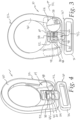
Fig. 1 is an isometric view of one embodiment of a coupling/connector according to the present invention, shown in a "ready" condition; -
Fig. 2 is another isometric view from a slightly different angle showing the connector ofFig. 1 in a "fall" condition; -
Fig. 3 is a front elevational view of the connector ofFigs. 1 and 2 , with a housing component shown in phantom for purposes of illustration; -
Fig. 4 is an isometric view of the connector ofFigs. 1-3 showing the housing component and a fall alarm/indicator component removed for purposes of illustration; -
Fig. 5 is an enlarged isometric view of a portion of the connector ofFigs. 1-4 , again with the housing component removed for purposes of illustration; -
Figs. 6A and 8B are enlarged views of selected components of the connector ofFigs. 1-5 , withFig. 6A showing the connector in the ready condition andFig. 6B showing the connector in the "fall" condition; -
Figs. 7-9 are isometric views of a fall alarm/indicator component of the connector ofFig. 6 , withFig. 7 also including a housing for the fall alarm/indicator component; -
Fig. 10 is an elevation view of another embodiment of the coupling/connector according to the present invention, with the connector shown in the "ready" condition and with a fall alarm/indicator component removed for purposes of illustration; -
Fig. 11 is a view similar toFig. 10 but showing the connector ofFig. 10 in the "fall" condition; and -
Fig. 12 is a view of the connector embodiment ofFigs. 10 and 11 with the fall alarm/indicator component shown diagrammatically. - A weight bearing fall protection coupling/
connector 10 is provided for connecting one piece of fall protection equipment to another piece of fall protection equipment to transfer the weight of the worker in the event of a fall, withFigs, 1 -9 showing an embodiment of theconnector 10 in the form of a swivel D-ring andFigs. 10-12 showing an embodiment of theconnector 10 in the form of a swivel Snap Hook. Theconnector 10 can be used with any type of fall protection equipment that is used to protect a worker during a fall event, including, for example, fall harnesses, static lines, fall lanyards, self-refracting lifelines, rope grab systems, and anchorage rescue devices. Typically, theconnector 10 will be utilized to connect a fall harness worn by a worker to some other piece of fall protection equipment, such as a self-refracting lifeline or fall lanyard, so as to transfer the weight/load of a worker during a fall event. - The
connector 10 includes afirst connection member 20 configured to attach theconnector 10 to one piece of fall protection equipment, such as a harness worn by a worker, and asecond connection member 22 configured to attach theconnector 10 to another piece of fall protection equipment, such as a self-retracting lifeline. The first andsecond connection members Figs. 1 ,3-5 , 8A and 10) wherein theconnector 10 has not experienced a fall event while connected to a worker and a "fall" position (shown inFigs. 2 , 8B and11 ) where theconnector 10 has experienced a fall event while connected to a worker. Theconnector 10 further includes abreakable component 24 operably connected to the first andsecond connection members breakable component 24 maintains theconnection members breakable component 24 allows theconnection members breakable component 24 has been broken by a weight transfer from a fall event. Theconnector 10 further includes a wireless fall alarm/indicator 26, with thefall indicator 26 including awireless transmitter 28 and aswitch 30 configured to activate thewireless transmitter 28 in response to movement of theconnection members wireless transmitter 28 is configured to transmit a wireless signal, shown generally at 32, indicating that a worker has fallen when thewireless transmitter 28 is activated by theswitch 30. In this regard, thewireless transmitter 28 will include circuitry, shown generally at 34, that is either activated by or responsive to theswitch 30 so as to operate thewireless transmitter 28 to transmit the wireless signal 32. The wireless signal 32 can be created and transmitted according to any suitable wireless protocol, many of which are known, including any suitable Wi-Fi, Bluetooth or RF protocol. Thefall indicator 26 can further include abattery 35 to power thewireless transmitter 28 andswitch 30, as required. Depending on the particular application, the battery may be replaceable or may be suitable for the life of theconnector 10. The wireless signal 32 is transmitted to other suitable wireless devices, such as, for example, cellular phones, smart phones, and/or other wireless receivers, carried by other workers and/or rescue personnel who can then be alerted by the other suitable devices that a fall event has occurred, in this regard, the wireless signal 32 will be transmitted continuously by thewireless transmitter 28 until steps are taken to deactivate the wireless signal 32 after the worker that experienced the fall event has been rescued. - The
first connection member 20 includes afirst connection portion 36 to attach thefirst connection member 20 to one piece of fall protection equipment, such as a harness worn by a worker, and aweight transfer portion 38 to transfer the weight of a worker to thesecond connection member 22. In the embodiment of theconnector 10 shown inFigs. 1-6 , thefirst connection portion 36 is a rectangular loop that is configured to receive a length of webbing or strap and is commonly used to connect with the webbing/strapping of a harness worn by a worker. In the embodiment of theconnector 10 shown inFigs. 10-12 , thefirst connection portion 36 is as shown in the form of a snap hook component that will typically be used to connect to a D-ring on a harness or to an anchor point on a structure. Thesecond connection member 22 includes asecond connection portion 40 to attach the second connection member to another piece of fall protection equipment, such as a fall lanyard, and aweight transfer portion 42 engaged with theweight transfer portion 38 of thefirst connection member 20 to transfer the weight of the worker from thefirst connection member 20 to thesecond connection member 22 during a fall event, in the embodiment of theconnector 10 shown inFigs. 1- 6, thesecond connection portion 40 is shown in the form of a circular loop that will typically be connected to a snap hook component of a static line, a safety lanyard, or an SRL. In the embodiment of the connector shown inFigs. 10-12 , thesecond connection portion 40 is shown in the form of a somewhat oval-shaped loop that will typically receive a rope/cable/line of another of a piece of fall protection equipment. - The
weight transfer portions connection members weight transfer members connection members weight transfer portion 38 includes abar 48 shown in the specific form of acylindrical shaft 48, and theweight transfer portion 42 includes anopening 50 shown in the specific configuration of acylindrical bore 50 that receives theshaft 48 for sliding and rotational movement of theshaft 48 in thebore 50. In this regard, while theconnection members breakable component 24 prevents theshaft 48 from sliding in thebore 50 until thebreakable component 24 is broken by the weight transfer of the worker during a fall event. In the illustrated embodiments, theweight transfer portion 38 includes acollar 52 that defines thestop surface 44 and theweight transfer portion 42 includes acollar 54 that defines thestop surface 48. - The
connection members - In the illustrated embodiments, the
breakable component 24 is ashear pin 24 that shears in response to a fall event. Theshear pin 24 is received in closely conformingbores connection members shear pin 24 is received in abore 56 formed in theshaft 48 and in a pair of spaced bores 58 that are formed in thecollar 54 of theweight transfer portion 42. Thus, it can be seen that theshear pin 24 retains thecollar 54 in a fixed position relative to theshaft 48 in the ready position as shown inFig. 6A , and that theshaft 48 andconnection member 20 are released by theshear pin 24 for movement relative to thecollar 54 and the connection member 32 in response to a fall event, as shown inFig. 6B . - With reference to the embodiment of the connector shown in
Figs. 1-9 , theswitch 30 includes a pair ofelectrical contacts connection members Figs. 3 ,5 and 6A , and that are pressed against each other with theconnection members Fig. 6B . In this regard in the illustrated embodiment, thestop surface 44 of thefirst connection member 20 engages theelectrical contact 60 and thestop surface 48 of thesecond connection member 22 engages the otherelectrical contact 62 as theconnection members surfaces electrical contacts 60 and 82 pressing thecontacts connection members contacts wireless transmitter 28 to send the wireless signal 32. - In the embodiment of the
connector 10 shown inFigs. 1-6 , thesecond connection portion 22 includes arelieved area 64 for receiving thefall indicator 26, which is mounted in ahousing 66 that can be attached to theconnection portion 22 using any suitable means, such as, for example, snap fit connections or permanent bonding. Ideally, thewireless transmitter 28 and associatedcircuitry 35 are enclosed in a sealed chamber that is IP68 and IP69K rated, with the twocontacts housing 66 includes apost 68 that extends between the tips of thecontacts 60 and 82 to maintain their spaced relationship until theconnector 10 experiences a fall event. - In the embodiment of the
conductor 10 shown inFigs. 10 and 11 , theswitch 30 is provided in the form of a magnetic reed switch, shown diagrammatically at 70, that is actuated in response to the movement of a magnetic field asconnection members connection members breakable component 24 is configured to generate a magnetic field that will actuate the magnetic reed switch 70, and, in the illustrated embodiment, theshear pin 24 is magnetized to generate a magnetic field that moves with theconnection member 20 as theconnection members circuitry 35 is triggered or senses the actuation of the magnetic reed switch 70 and activates thewireless transmitter 28 to send the wireless signal 32. - It should be appreciated that while specific embodiments have been shown herein that will prove advantageous for a number of applications, this disclosure anticipates other embodiments of couplings/
connectors 10 that will utilize the concepts disclosed herein and that no limitations to specific geometric configurations or specific configurations of the components are intended unless expressly recited in an appended claims. In this regard, for example, while specific geometries have been shown for theconnection portions weight transfer portion 38 has been shown in the form of ashaft 48 that is received in abore 50, other geometric shapes and other configurations may be desirable depending upon the specifics of a particular application. - It should be appreciated that the
connector 10 disclosed herein provides a simple and reliable structure for alerting workers and emergency personnel remote from a fall event that a worker has experienced a fall event and is suspended. In this regard, it should be appreciated that the embodiment of theconnector 10 disclosed herein utilize structure that has already been successfully employed in the industry, with proven reliability and simplicity, with a minimum amount of modification to this structure.
Claims (6)
- A weight bearing fall protection connector (10) for connecting one piece of fall protection equipment to another piece of fall protection equipment to transfer the weight of a worker in the event of a fall, the connector (10) comprising:a first connection member (20) configured to attach the connector (10) to one piece of fall protection equipment and having a first weight transfer portion (38), wherein the first weight transfer portion (38) comprises a bar (48) and a first collar (52), wherein the first collar (52) is connected to the bar (48) at the opposite end of the end at which the one piece of fall protection equipment is to be attached, and wherein the first collar (52) defines a first stop surface (44);a second connection member (22) configured to attach the connector (10) to another piece of fall protection equipment and having a second weight transfer portion (42), the second weight transfer portion (42) comprising an opening (50), configured to receive the bar (48) for sliding and rotational movement of the bar (48) in the opening (50), and a second collar (54), wherein the second collar (54) is positioned on the bar (48) between the first collar (52) and the opening (50), wherein the second collar (54) defines a second stop surface (46) facing the first stop surface (44), and wherein the first and second connection members (20, 22) have a ready position where the connector (10) has not experienced a fall event while connected to the worker and a fall position where the connector (10) has experienced a fall event while connected to the worker;a shear pin (24) that is received in a bore (56) formed in the bar (48) and in a pair of spaced bores (58) formed in the second collar (54), the shear pin (24) having a retaining condition and a broken condition, wherein in the retaining condition the shear pin (24) retains the second collar (54) fixed relative to the bar (48) so as to maintain the connection members (20, 22) in the ready position, wherein in the broken condition the bar (48) is released for sliding movement relative to the second collar (54) so as to allow the connection members (20, 22) to move to their fall position after the shear pin (24) has been sheared by a weight transfer of the worker from a fall event, wherein in the ready position the first stop surface (44) of the first collar (52) is separated from the second stop surface (46) of the second collar (54), and wherein in the fall position the first stop surface (44) of the first collar (52) engages the second stop surface (46) of the second collar (54); anda wireless fall indicator (26) comprising:a wireless transmitter (28), anda switch (30) including a pair of electrical contacts (60, 62) that are placed between the first and second stop surfaces (44, 46) defined by the first collar (52) and the second collar (54) respectively, wherein the pair of electrical contacts (60, 62) are spaced apart from each other when the connection members (20, 22) are in the ready position, and wherein the first stop surface (44) of the first connection member (20) engages a first electrical contact (60) and the second stop surface (46) of the second connection member (22) engages a second electrical contact (62) as the connection members (20,22) move from the ready position to the fall position, and wherein the engagement of the first and second stop surfaces (44, 46) with the pair of electrical contacts (60, 62) presses the pair of electrical contacts (60, 62) against each other thereby activating the wireless transmitter (28) to transmit a wireless signal indicating that the worker has fallen when the wireless transmitter (28) is activated by the switch (30).
- The weight bearing fall protection connector (10) of claim 1 wherein:the first connection member (20) comprises a first connection portion (36) to attach the first connection member (20) to one piece of fall protection equipment; andthe second connection member (22) comprises a second connection portion (40) to attach the second connection member (22) to another piece of fall protection equipment.
- The weight bearing fall protection connector (10) of claim 1 wherein the bar (48) is a cylindrical shaft and the opening (50) is a cylindrical bore that allow the connection members (20, 22) to swivel relative to each other in the ready position.
- The weight bearing fall protection connector (10) of any preceding claim wherein at least one of the connection members (20, 22) or the shear pin (24) is configured to generate a magnetic field, and the switch (30) is a magnetic reed switch that is actuated in response to movement of the magnetic field as the connection members (20, 22) move from the ready position to the fall position.
- The weight bearing fall protection connector (10) of any preceding claim wherein the connector (10) is a D-ring connector.
- The weight bearing fall protection connector (10) of any preceding claim wherein the connector (10) is a Snap Hook connector.
Priority Applications (1)
| Application Number | Priority Date | Filing Date | Title |
|---|---|---|---|
| EP23150763.3A EP4223371B1 (en) | 2016-04-14 | 2016-04-14 | Weight bearing fall protection connector having a wireless fall indicator |
Applications Claiming Priority (1)
| Application Number | Priority Date | Filing Date | Title |
|---|---|---|---|
| PCT/US2016/027429 WO2017180121A1 (en) | 2016-04-14 | 2016-04-14 | Weight bearing fall protection connector having a wireless fall indicator |
Related Child Applications (2)
| Application Number | Title | Priority Date | Filing Date |
|---|---|---|---|
| EP23150763.3A Division EP4223371B1 (en) | 2016-04-14 | 2016-04-14 | Weight bearing fall protection connector having a wireless fall indicator |
| EP23150763.3A Division-Into EP4223371B1 (en) | 2016-04-14 | 2016-04-14 | Weight bearing fall protection connector having a wireless fall indicator |
Publications (3)
| Publication Number | Publication Date |
|---|---|
| EP3442669A1 EP3442669A1 (en) | 2019-02-20 |
| EP3442669A4 EP3442669A4 (en) | 2020-01-01 |
| EP3442669B1 true EP3442669B1 (en) | 2023-05-31 |
Family
ID=60042015
Family Applications (2)
| Application Number | Title | Priority Date | Filing Date |
|---|---|---|---|
| EP16898807.9A Active EP3442669B1 (en) | 2016-04-14 | 2016-04-14 | Weight bearing fall protection connector having a wireless fall indicator |
| EP23150763.3A Active EP4223371B1 (en) | 2016-04-14 | 2016-04-14 | Weight bearing fall protection connector having a wireless fall indicator |
Family Applications After (1)
| Application Number | Title | Priority Date | Filing Date |
|---|---|---|---|
| EP23150763.3A Active EP4223371B1 (en) | 2016-04-14 | 2016-04-14 | Weight bearing fall protection connector having a wireless fall indicator |
Country Status (4)
| Country | Link |
|---|---|
| US (2) | US10843016B2 (en) |
| EP (2) | EP3442669B1 (en) |
| CN (3) | CN109310895B (en) |
| WO (1) | WO2017180121A1 (en) |
Families Citing this family (11)
| Publication number | Priority date | Publication date | Assignee | Title |
|---|---|---|---|---|
| JP7402823B2 (en) * | 2018-05-23 | 2023-12-21 | スリーエム イノベイティブ プロパティズ カンパニー | Shock indicators for fall protection devices and how to use them |
| US12429494B2 (en) | 2019-01-14 | 2025-09-30 | Msa Technology, Llc | Fall protection compliance system and method |
| US12412464B2 (en) | 2019-01-14 | 2025-09-09 | Msa Technology, Llc | Fall protection compliance system and method |
| EP4600928A3 (en) * | 2019-01-14 | 2026-02-25 | MSA Technology, LLC | Fall protection compliance system and method |
| USD967550S1 (en) * | 2020-06-10 | 2022-10-18 | Vintech Industries Inc. | Face shield strap cinch |
| US11663897B2 (en) * | 2020-07-16 | 2023-05-30 | Joseph Clinton Meyers | Apparatus for anchoring a fall protection system and transmitting a fall alert |
| JP2022090493A (en) * | 2020-12-07 | 2022-06-17 | 豊田合成株式会社 | Air bag device |
| US11628320B2 (en) * | 2021-01-25 | 2023-04-18 | Yoke Industrial Corp. | Fall arrest connector |
| US12444287B1 (en) * | 2021-09-07 | 2025-10-14 | New River Electrical Innovations, LLC | Alarm activated safety device |
| US20250303205A1 (en) * | 2022-06-16 | 2025-10-02 | 3M Innovative Properties Company | System and Method for Detecting Fall Event |
| WO2024018325A1 (en) * | 2022-07-20 | 2024-01-25 | 3M Innovative Properties Company | Composite connector comprising deformable section with interruptible signal-transmissive pathway |
Family Cites Families (18)
| Publication number | Priority date | Publication date | Assignee | Title |
|---|---|---|---|---|
| US4660679A (en) * | 1986-02-10 | 1987-04-28 | Meyer Ostrobrod | Safety alarm tripod |
| US5220977A (en) | 1992-02-18 | 1993-06-22 | D B Industries, Inc. | Fall indicator for use with fall arresting devices |
| FR2755236B3 (en) | 1996-10-24 | 1998-12-24 | Henri Joachim Victor Brunet | EFFORT SENSOR WITH RADIO ALARM FOR THE PROTECTION OF PERSONS OR INDUSTRIAL DEVICES |
| JP2005218725A (en) * | 2004-02-09 | 2005-08-18 | Fujii Denko Co Ltd | Safety band hook monitor device for vehicle for high lift work |
| AU2006207863B2 (en) * | 2006-02-21 | 2009-05-07 | Fall Alert Industries Pty Ltd | Fall notifying apparatus |
| US8325053B2 (en) * | 2009-03-10 | 2012-12-04 | JCJ Inc. | Personal fall protection monitoring system |
| JP5116815B2 (en) * | 2009-10-20 | 2013-01-09 | 藤井電工株式会社 | Safety belt and its usage confirmation system |
| US8675823B2 (en) * | 2009-10-30 | 2014-03-18 | Hooten Investments, Inc. | Method and apparatus for activating a communication device operably connected to a safety lanyard |
| US8973705B2 (en) | 2010-09-01 | 2015-03-10 | Climb Tech, Llc | Swivel D-ring attachment point |
| GB2486012A (en) * | 2010-12-01 | 2012-06-06 | Dessa Ltd | Alarm for fall arrest system |
| WO2012104833A2 (en) * | 2011-02-03 | 2012-08-09 | Hip Hope Technologies Ltd. | Hip protector system and method for hip fracture prevention |
| US9238156B2 (en) * | 2011-07-11 | 2016-01-19 | Msa Technology, Llc | Personal fall limiter arrangement and user connection arrangement therefor |
| GB2510096B (en) * | 2012-11-01 | 2015-08-26 | Skanska Uk Plc | Safety equipment |
| CN202961570U (en) * | 2013-01-05 | 2013-06-05 | 宁波天弘电力器具有限公司 | Hook with impact display device |
| CN203311589U (en) * | 2013-06-26 | 2013-11-27 | 重庆工业设备安装集团有限公司 | Vertical-horizontal double-lifeline protection alarm system |
| US10138102B2 (en) * | 2013-07-23 | 2018-11-27 | Viki V. Walbridge | Warning and message delivery and logging system utilizable in a fall arresting and prevention device and method of same |
| CN203829509U (en) * | 2014-05-05 | 2014-09-17 | 李华敏 | Anti-fall individual protection alarm device for overhead safe operation |
| US10610710B2 (en) * | 2016-03-11 | 2020-04-07 | Honeywell International Inc. | Fall protection radio frequency emergency beacon |
-
2016
- 2016-04-14 CN CN201680086797.9A patent/CN109310895B/en active Active
- 2016-04-14 EP EP16898807.9A patent/EP3442669B1/en active Active
- 2016-04-14 US US16/093,729 patent/US10843016B2/en active Active
- 2016-04-14 WO PCT/US2016/027429 patent/WO2017180121A1/en not_active Ceased
- 2016-04-14 EP EP23150763.3A patent/EP4223371B1/en active Active
- 2016-04-14 CN CN202110653475.0A patent/CN113368428B/en active Active
- 2016-04-14 CN CN202110653464.2A patent/CN113384829B/en active Active
-
2020
- 2020-10-21 US US17/076,486 patent/US11730984B2/en active Active
Also Published As
| Publication number | Publication date |
|---|---|
| CN113368428B (en) | 2022-11-15 |
| EP3442669A4 (en) | 2020-01-01 |
| EP4223371C0 (en) | 2025-09-03 |
| US20210031062A1 (en) | 2021-02-04 |
| EP4223371A1 (en) | 2023-08-09 |
| US20190083825A1 (en) | 2019-03-21 |
| US10843016B2 (en) | 2020-11-24 |
| EP3442669A1 (en) | 2019-02-20 |
| US11730984B2 (en) | 2023-08-22 |
| CN109310895A (en) | 2019-02-05 |
| CN113384829A (en) | 2021-09-14 |
| CN113368428A (en) | 2021-09-10 |
| WO2017180121A1 (en) | 2017-10-19 |
| CN109310895B (en) | 2021-06-01 |
| CN113384829B (en) | 2023-01-13 |
| EP4223371B1 (en) | 2025-09-03 |
Similar Documents
| Publication | Publication Date | Title |
|---|---|---|
| EP4223371B1 (en) | Weight bearing fall protection connector having a wireless fall indicator | |
| US20240269495A1 (en) | Safety equipment | |
| US8675823B2 (en) | Method and apparatus for activating a communication device operably connected to a safety lanyard | |
| US11024153B2 (en) | Fall detection alert/alarm device and method | |
| CN114173884B (en) | Fall protection device with multi-mode inductive sensing | |
| WO2023287473A1 (en) | Apparatus for anchoring a fall protection system and transmitting a fall alert | |
| GB2486012A (en) | Alarm for fall arrest system | |
| CN219662691U (en) | Retractable shock attenuation safety rope that prevents weighing down | |
| WO2015135161A1 (en) | An arrester device and a system for monitoring thereof | |
| CN119925847A (en) | A condition monitoring intelligent seat belt |
Legal Events
| Date | Code | Title | Description |
|---|---|---|---|
| STAA | Information on the status of an ep patent application or granted ep patent |
Free format text: STATUS: THE INTERNATIONAL PUBLICATION HAS BEEN MADE |
|
| PUAI | Public reference made under article 153(3) epc to a published international application that has entered the european phase |
Free format text: ORIGINAL CODE: 0009012 |
|
| STAA | Information on the status of an ep patent application or granted ep patent |
Free format text: STATUS: REQUEST FOR EXAMINATION WAS MADE |
|
| 17P | Request for examination filed |
Effective date: 20181113 |
|
| AK | Designated contracting states |
Kind code of ref document: A1 Designated state(s): AL AT BE BG CH CY CZ DE DK EE ES FI FR GB GR HR HU IE IS IT LI LT LU LV MC MK MT NL NO PL PT RO RS SE SI SK SM TR |
|
| AX | Request for extension of the european patent |
Extension state: BA ME |
|
| DAV | Request for validation of the european patent (deleted) | ||
| DAX | Request for extension of the european patent (deleted) | ||
| A4 | Supplementary search report drawn up and despatched |
Effective date: 20191128 |
|
| RIC1 | Information provided on ipc code assigned before grant |
Ipc: F16B 45/02 20060101ALI20191122BHEP Ipc: A62B 35/00 20060101AFI20191122BHEP |
|
| STAA | Information on the status of an ep patent application or granted ep patent |
Free format text: STATUS: EXAMINATION IS IN PROGRESS |
|
| 17Q | First examination report despatched |
Effective date: 20201023 |
|
| GRAP | Despatch of communication of intention to grant a patent |
Free format text: ORIGINAL CODE: EPIDOSNIGR1 |
|
| STAA | Information on the status of an ep patent application or granted ep patent |
Free format text: STATUS: GRANT OF PATENT IS INTENDED |
|
| INTG | Intention to grant announced |
Effective date: 20220726 |
|
| GRAJ | Information related to disapproval of communication of intention to grant by the applicant or resumption of examination proceedings by the epo deleted |
Free format text: ORIGINAL CODE: EPIDOSDIGR1 |
|
| STAA | Information on the status of an ep patent application or granted ep patent |
Free format text: STATUS: EXAMINATION IS IN PROGRESS |
|
| GRAS | Grant fee paid |
Free format text: ORIGINAL CODE: EPIDOSNIGR3 |
|
| STAA | Information on the status of an ep patent application or granted ep patent |
Free format text: STATUS: GRANT OF PATENT IS INTENDED |
|
| GRAP | Despatch of communication of intention to grant a patent |
Free format text: ORIGINAL CODE: EPIDOSNIGR1 |
|
| INTC | Intention to grant announced (deleted) | ||
| INTG | Intention to grant announced |
Effective date: 20221223 |
|
| GRAA | (expected) grant |
Free format text: ORIGINAL CODE: 0009210 |
|
| STAA | Information on the status of an ep patent application or granted ep patent |
Free format text: STATUS: THE PATENT HAS BEEN GRANTED |
|
| AK | Designated contracting states |
Kind code of ref document: B1 Designated state(s): AL AT BE BG CH CY CZ DE DK EE ES FI FR GB GR HR HU IE IS IT LI LT LU LV MC MK MT NL NO PL PT RO RS SE SI SK SM TR |
|
| REG | Reference to a national code |
Ref country code: GB Ref legal event code: FG4D Ref country code: CH Ref legal event code: EP |
|
| REG | Reference to a national code |
Ref country code: AT Ref legal event code: REF Ref document number: 1570612 Country of ref document: AT Kind code of ref document: T Effective date: 20230615 Ref country code: DE Ref legal event code: R096 Ref document number: 602016079758 Country of ref document: DE |
|
| REG | Reference to a national code |
Ref country code: IE Ref legal event code: FG4D |
|
| REG | Reference to a national code |
Ref country code: LT Ref legal event code: MG9D |
|
| REG | Reference to a national code |
Ref country code: NL Ref legal event code: MP Effective date: 20230531 |
|
| REG | Reference to a national code |
Ref country code: AT Ref legal event code: MK05 Ref document number: 1570612 Country of ref document: AT Kind code of ref document: T Effective date: 20230531 |
|
| PG25 | Lapsed in a contracting state [announced via postgrant information from national office to epo] |
Ref country code: SE Free format text: LAPSE BECAUSE OF FAILURE TO SUBMIT A TRANSLATION OF THE DESCRIPTION OR TO PAY THE FEE WITHIN THE PRESCRIBED TIME-LIMIT Effective date: 20230531 Ref country code: NO Free format text: LAPSE BECAUSE OF FAILURE TO SUBMIT A TRANSLATION OF THE DESCRIPTION OR TO PAY THE FEE WITHIN THE PRESCRIBED TIME-LIMIT Effective date: 20230831 Ref country code: ES Free format text: LAPSE BECAUSE OF FAILURE TO SUBMIT A TRANSLATION OF THE DESCRIPTION OR TO PAY THE FEE WITHIN THE PRESCRIBED TIME-LIMIT Effective date: 20230531 Ref country code: AT Free format text: LAPSE BECAUSE OF FAILURE TO SUBMIT A TRANSLATION OF THE DESCRIPTION OR TO PAY THE FEE WITHIN THE PRESCRIBED TIME-LIMIT Effective date: 20230531 |
|
| PG25 | Lapsed in a contracting state [announced via postgrant information from national office to epo] |
Ref country code: RS Free format text: LAPSE BECAUSE OF FAILURE TO SUBMIT A TRANSLATION OF THE DESCRIPTION OR TO PAY THE FEE WITHIN THE PRESCRIBED TIME-LIMIT Effective date: 20230531 Ref country code: PL Free format text: LAPSE BECAUSE OF FAILURE TO SUBMIT A TRANSLATION OF THE DESCRIPTION OR TO PAY THE FEE WITHIN THE PRESCRIBED TIME-LIMIT Effective date: 20230531 Ref country code: NL Free format text: LAPSE BECAUSE OF FAILURE TO SUBMIT A TRANSLATION OF THE DESCRIPTION OR TO PAY THE FEE WITHIN THE PRESCRIBED TIME-LIMIT Effective date: 20230531 Ref country code: LV Free format text: LAPSE BECAUSE OF FAILURE TO SUBMIT A TRANSLATION OF THE DESCRIPTION OR TO PAY THE FEE WITHIN THE PRESCRIBED TIME-LIMIT Effective date: 20230531 Ref country code: LT Free format text: LAPSE BECAUSE OF FAILURE TO SUBMIT A TRANSLATION OF THE DESCRIPTION OR TO PAY THE FEE WITHIN THE PRESCRIBED TIME-LIMIT Effective date: 20230531 Ref country code: IS Free format text: LAPSE BECAUSE OF FAILURE TO SUBMIT A TRANSLATION OF THE DESCRIPTION OR TO PAY THE FEE WITHIN THE PRESCRIBED TIME-LIMIT Effective date: 20230930 Ref country code: HR Free format text: LAPSE BECAUSE OF FAILURE TO SUBMIT A TRANSLATION OF THE DESCRIPTION OR TO PAY THE FEE WITHIN THE PRESCRIBED TIME-LIMIT Effective date: 20230531 Ref country code: GR Free format text: LAPSE BECAUSE OF FAILURE TO SUBMIT A TRANSLATION OF THE DESCRIPTION OR TO PAY THE FEE WITHIN THE PRESCRIBED TIME-LIMIT Effective date: 20230901 |
|
| PG25 | Lapsed in a contracting state [announced via postgrant information from national office to epo] |
Ref country code: FI Free format text: LAPSE BECAUSE OF FAILURE TO SUBMIT A TRANSLATION OF THE DESCRIPTION OR TO PAY THE FEE WITHIN THE PRESCRIBED TIME-LIMIT Effective date: 20230531 |
|
| PG25 | Lapsed in a contracting state [announced via postgrant information from national office to epo] |
Ref country code: SK Free format text: LAPSE BECAUSE OF FAILURE TO SUBMIT A TRANSLATION OF THE DESCRIPTION OR TO PAY THE FEE WITHIN THE PRESCRIBED TIME-LIMIT Effective date: 20230531 |
|
| PG25 | Lapsed in a contracting state [announced via postgrant information from national office to epo] |
Ref country code: SM Free format text: LAPSE BECAUSE OF FAILURE TO SUBMIT A TRANSLATION OF THE DESCRIPTION OR TO PAY THE FEE WITHIN THE PRESCRIBED TIME-LIMIT Effective date: 20230531 Ref country code: SK Free format text: LAPSE BECAUSE OF FAILURE TO SUBMIT A TRANSLATION OF THE DESCRIPTION OR TO PAY THE FEE WITHIN THE PRESCRIBED TIME-LIMIT Effective date: 20230531 Ref country code: RO Free format text: LAPSE BECAUSE OF FAILURE TO SUBMIT A TRANSLATION OF THE DESCRIPTION OR TO PAY THE FEE WITHIN THE PRESCRIBED TIME-LIMIT Effective date: 20230531 Ref country code: PT Free format text: LAPSE BECAUSE OF FAILURE TO SUBMIT A TRANSLATION OF THE DESCRIPTION OR TO PAY THE FEE WITHIN THE PRESCRIBED TIME-LIMIT Effective date: 20231002 Ref country code: EE Free format text: LAPSE BECAUSE OF FAILURE TO SUBMIT A TRANSLATION OF THE DESCRIPTION OR TO PAY THE FEE WITHIN THE PRESCRIBED TIME-LIMIT Effective date: 20230531 Ref country code: DK Free format text: LAPSE BECAUSE OF FAILURE TO SUBMIT A TRANSLATION OF THE DESCRIPTION OR TO PAY THE FEE WITHIN THE PRESCRIBED TIME-LIMIT Effective date: 20230531 Ref country code: CZ Free format text: LAPSE BECAUSE OF FAILURE TO SUBMIT A TRANSLATION OF THE DESCRIPTION OR TO PAY THE FEE WITHIN THE PRESCRIBED TIME-LIMIT Effective date: 20230531 |
|
| REG | Reference to a national code |
Ref country code: DE Ref legal event code: R097 Ref document number: 602016079758 Country of ref document: DE |
|
| PLBE | No opposition filed within time limit |
Free format text: ORIGINAL CODE: 0009261 |
|
| STAA | Information on the status of an ep patent application or granted ep patent |
Free format text: STATUS: NO OPPOSITION FILED WITHIN TIME LIMIT |
|
| PG25 | Lapsed in a contracting state [announced via postgrant information from national office to epo] |
Ref country code: SI Free format text: LAPSE BECAUSE OF FAILURE TO SUBMIT A TRANSLATION OF THE DESCRIPTION OR TO PAY THE FEE WITHIN THE PRESCRIBED TIME-LIMIT Effective date: 20230531 |
|
| 26N | No opposition filed |
Effective date: 20240301 |
|
| PG25 | Lapsed in a contracting state [announced via postgrant information from national office to epo] |
Ref country code: SI Free format text: LAPSE BECAUSE OF FAILURE TO SUBMIT A TRANSLATION OF THE DESCRIPTION OR TO PAY THE FEE WITHIN THE PRESCRIBED TIME-LIMIT Effective date: 20230531 Ref country code: IT Free format text: LAPSE BECAUSE OF FAILURE TO SUBMIT A TRANSLATION OF THE DESCRIPTION OR TO PAY THE FEE WITHIN THE PRESCRIBED TIME-LIMIT Effective date: 20230531 |
|
| PG25 | Lapsed in a contracting state [announced via postgrant information from national office to epo] |
Ref country code: BG Free format text: LAPSE BECAUSE OF FAILURE TO SUBMIT A TRANSLATION OF THE DESCRIPTION OR TO PAY THE FEE WITHIN THE PRESCRIBED TIME-LIMIT Effective date: 20230531 |
|
| PG25 | Lapsed in a contracting state [announced via postgrant information from national office to epo] |
Ref country code: MC Free format text: LAPSE BECAUSE OF FAILURE TO SUBMIT A TRANSLATION OF THE DESCRIPTION OR TO PAY THE FEE WITHIN THE PRESCRIBED TIME-LIMIT Effective date: 20230531 |
|
| PG25 | Lapsed in a contracting state [announced via postgrant information from national office to epo] |
Ref country code: MC Free format text: LAPSE BECAUSE OF FAILURE TO SUBMIT A TRANSLATION OF THE DESCRIPTION OR TO PAY THE FEE WITHIN THE PRESCRIBED TIME-LIMIT Effective date: 20230531 Ref country code: BG Free format text: LAPSE BECAUSE OF FAILURE TO SUBMIT A TRANSLATION OF THE DESCRIPTION OR TO PAY THE FEE WITHIN THE PRESCRIBED TIME-LIMIT Effective date: 20230531 |
|
| REG | Reference to a national code |
Ref country code: CH Ref legal event code: PL |
|
| PG25 | Lapsed in a contracting state [announced via postgrant information from national office to epo] |
Ref country code: LU Free format text: LAPSE BECAUSE OF NON-PAYMENT OF DUE FEES Effective date: 20240414 |
|
| REG | Reference to a national code |
Ref country code: BE Ref legal event code: MM Effective date: 20240430 |
|
| PG25 | Lapsed in a contracting state [announced via postgrant information from national office to epo] |
Ref country code: LU Free format text: LAPSE BECAUSE OF NON-PAYMENT OF DUE FEES Effective date: 20240414 |
|
| PG25 | Lapsed in a contracting state [announced via postgrant information from national office to epo] |
Ref country code: BE Free format text: LAPSE BECAUSE OF NON-PAYMENT OF DUE FEES Effective date: 20240430 |
|
| PG25 | Lapsed in a contracting state [announced via postgrant information from national office to epo] |
Ref country code: BE Free format text: LAPSE BECAUSE OF NON-PAYMENT OF DUE FEES Effective date: 20240430 Ref country code: CH Free format text: LAPSE BECAUSE OF NON-PAYMENT OF DUE FEES Effective date: 20240430 |
|
| PG25 | Lapsed in a contracting state [announced via postgrant information from national office to epo] |
Ref country code: IE Free format text: LAPSE BECAUSE OF NON-PAYMENT OF DUE FEES Effective date: 20240414 |
|
| REG | Reference to a national code |
Ref country code: DE Ref legal event code: R081 Ref document number: 602016079758 Country of ref document: DE Owner name: HONEYWELL SAFETY PRODUCTS USA, INC., WILMINGTO, US Free format text: FORMER OWNER: HONEYWELL INTERNATIONAL INC., MORRIS PLAINS, NJ, US |
|
| REG | Reference to a national code |
Ref country code: GB Ref legal event code: 732E Free format text: REGISTERED BETWEEN 20250515 AND 20250521 |
|
| PGFP | Annual fee paid to national office [announced via postgrant information from national office to epo] |
Ref country code: DE Payment date: 20250428 Year of fee payment: 10 |
|
| PGFP | Annual fee paid to national office [announced via postgrant information from national office to epo] |
Ref country code: GB Payment date: 20250422 Year of fee payment: 10 |
|
| PGFP | Annual fee paid to national office [announced via postgrant information from national office to epo] |
Ref country code: FR Payment date: 20250424 Year of fee payment: 10 |
|
| PG25 | Lapsed in a contracting state [announced via postgrant information from national office to epo] |
Ref country code: CY Free format text: LAPSE BECAUSE OF FAILURE TO SUBMIT A TRANSLATION OF THE DESCRIPTION OR TO PAY THE FEE WITHIN THE PRESCRIBED TIME-LIMIT; INVALID AB INITIO Effective date: 20160414 |
|
| PG25 | Lapsed in a contracting state [announced via postgrant information from national office to epo] |
Ref country code: HU Free format text: LAPSE BECAUSE OF FAILURE TO SUBMIT A TRANSLATION OF THE DESCRIPTION OR TO PAY THE FEE WITHIN THE PRESCRIBED TIME-LIMIT; INVALID AB INITIO Effective date: 20160414 |