EP3442267A1 - Device and method of handling a bearer change in dual connectivity - Google Patents
Device and method of handling a bearer change in dual connectivity Download PDFInfo
- Publication number
- EP3442267A1 EP3442267A1 EP18188527.8A EP18188527A EP3442267A1 EP 3442267 A1 EP3442267 A1 EP 3442267A1 EP 18188527 A EP18188527 A EP 18188527A EP 3442267 A1 EP3442267 A1 EP 3442267A1
- Authority
- EP
- European Patent Office
- Prior art keywords
- communication device
- drb
- rrc
- response
- deliv
- Prior art date
- Legal status (The legal status is an assumption and is not a legal conclusion. Google has not performed a legal analysis and makes no representation as to the accuracy of the status listed.)
- Granted
Links
Images

Classifications
-
- H—ELECTRICITY
- H04—ELECTRIC COMMUNICATION TECHNIQUE
- H04W—WIRELESS COMMUNICATION NETWORKS
- H04W36/00—Hand-off or reselection arrangements
- H04W36/0005—Control or signalling for completing the hand-off
- H04W36/0055—Transmission or use of information for re-establishing the radio link
- H04W36/0069—Transmission or use of information for re-establishing the radio link in case of dual connectivity, e.g. decoupled uplink/downlink
- H04W36/00695—Transmission or use of information for re-establishing the radio link in case of dual connectivity, e.g. decoupled uplink/downlink using split of the control plane or user plane
-
- H—ELECTRICITY
- H04—ELECTRIC COMMUNICATION TECHNIQUE
- H04W—WIRELESS COMMUNICATION NETWORKS
- H04W76/00—Connection management
- H04W76/10—Connection setup
- H04W76/15—Setup of multiple wireless link connections
-
- H—ELECTRICITY
- H04—ELECTRIC COMMUNICATION TECHNIQUE
- H04W—WIRELESS COMMUNICATION NETWORKS
- H04W76/00—Connection management
- H04W76/20—Manipulation of established connections
- H04W76/27—Transitions between radio resource control [RRC] states
-
- H—ELECTRICITY
- H04—ELECTRIC COMMUNICATION TECHNIQUE
- H04W—WIRELESS COMMUNICATION NETWORKS
- H04W88/00—Devices specially adapted for wireless communication networks, e.g. terminals, base stations or access point devices
- H04W88/02—Terminal devices
- H04W88/06—Terminal devices adapted for operation in multiple networks or having at least two operational modes, e.g. multi-mode terminals
-
- H—ELECTRICITY
- H04—ELECTRIC COMMUNICATION TECHNIQUE
- H04W—WIRELESS COMMUNICATION NETWORKS
- H04W36/00—Hand-off or reselection arrangements
- H04W36/0005—Control or signalling for completing the hand-off
- H04W36/0011—Control or signalling for completing the hand-off for data sessions of end-to-end connection
- H04W36/0033—Control or signalling for completing the hand-off for data sessions of end-to-end connection with transfer of context information
Definitions
- the present invention relates to a device and a method used in a wireless communication system, and more particularly, to a device and a method of handling a bearer change in dual connectivity.
- a UE may communicate with a gNB in a standalone or a non-standalone mode.
- the UE may communicate with the gNB in dual connectivity (DC) with an evolved Node-B (eNB) or another gNB.
- eNB evolved Node-B
- the UE may only communicate with the gNB without the DC.
- a bearer may be configured to the UE in the DC. It is still unknown how to process (e.g., receive) data, if a type of the bearer is changed. Accordingly, the UE cannot operate properly. Thus, it is important to define an operation for the UE in the situation to solve the problem.
- the present invention therefore provides a method and related communication device for handling a bearer change in dual connectivity to solve the abovementioned problem.
- a network comprising a first base station (BS) and a second BS comprises at least one storage device; and at least one processing circuit coupled to the at least one storage device.
- the at least one storage device stores, and the at least one processing circuit is configured to execute instructions of: the first BS transmitting a first radio resource control (RRC) message on a signaling radio bearer (SRB) to a communication device, wherein the first RRC message configures a data radio bearer (DRB) ; the first BS receiving a first RRC response message from the communication device on the SRB, in response to the first RRC message; the first BS receiving a first plurality of packet data convergence protocol (PDCP) Service Data Units (SDUs) associated to the DRB from the communication device; the first BS processing the first plurality of PDCP SDUs according to a first RX_NEXT, a first RX_DELIV and a first RX_REORD which are associated to the DRB; the first BS performing a dual connectivity (DC)
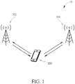
- Fig. 1 is a schematic diagram of a wireless communication system 10 according to an example of the present invention.
- the wireless communication system 10 is briefly composed of a communication device 100, a base station (BS) 102 and a BS 104.
- the communication device 100, the BS 102 and the BS 104 are simply utilized for illustrating the structure of the wireless communication system 10.
- the communication device 100 may be configured to communicate with the BS 102 only, i.e., not in dual connectivity (DC).
- the BS 102 may command the communication device 100 to hand over to the BS 104.
- the communication device 100 may be configured to communicate with the BSs 102 and 104 simultaneously according to the DC configured to the communication device 100.
- the communication device 100 receives protocol data units (PDUs) from the BS 102 at one carrier frequency and the BS 104 at another carrier frequency, or the communication device 100 transmits PDUs to the BS 102 at one carrier frequency and/or the BS 104 at another carrier frequency.
- the communication device 100 receives PDUs from at least one cell of the BS 102 and/or at least one cell of the BS 104.
- the communication device 100 transmits the PDUs to at least one cell of the BS 102 and/or at least one cell of the BS 104.
- one of the BSs 102 and 104 is a master node (MN) and the other BS is a secondary node (SN).
- MN master node
- SN secondary node
- the communication device 100 may be a user equipment (UE), a mobile phone, a laptop, a tablet computer, an electronic book, a portable computer system, a vehicle or an airplane.
- UE user equipment
- the communication device 100 is a transmitter and the BS (s) 102 and/or 104 are/is a receiver (s)
- DL downlink
- the BS(s) 102 and/or 104 are/is a transmitter(s) and the communication device 100 is a receiver.
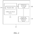
- Fig. 2 is a schematic diagram of a communication device 20 according to an example of the present invention.
- the communication device 20 may be the communication device 100, the BS (s) 102 and/or 104 shown in Fig. 1 , but is not limited herein.
- the communication device 20 may include at least one processing circuit 200 such as a microprocessor or Application Specific Integrated Circuit (ASIC), at least one storage device 210 and at least one communication interfacing device 220.
- the at least one storage device 210 may be any data storage device that may store program codes 214, accessed and executed by the at least one processing circuit 200.
- ASIC Application Specific Integrated Circuit
- Examples of the at least one storage device 210 include but are not limited to a subscriber identity module (SIM), read-only memory (ROM), flash memory, random-access memory (RAM), hard disk, optical data storage device, non-volatile storage device, non-transitory computer-readable medium (e.g., tangible media), etc.
- SIM subscriber identity module
- ROM read-only memory
- RAM random-access memory
- the at least one communication interfacing device 220 is preferably at least one transceiver and is used to transmit and receive signals (e.g., data, messages and/or packets) according to processing results of the at least one processing circuit 200.
- a UE is used for representing the communication device 100 in Fig. 1 , to simplify the illustration of the examples.
- the UE connecting to the MN has a first signalling radio bearer (SRB), and the MN transmits a measurement configuration on the first SRB to the UE.
- the UE transmits a measurement report on the first SRB to the MN according to the measurement configuration.
- the MN initiates a SN Addition procedure (e.g., SgNB Addition procedure) with the SN for the UE in response to the measurement report.
- the MN configures the UE to connect to the SN in response to the SN Addition procedure by transmitting a radio resource control (RRC) message on the first SRB to the UE.
- the RRC message includes a SN configuration (e.g., SCG configuration) for the UE to connect to the SN.
- the UE may setup a radio bearer (RB).
- RB radio bearer
- a protocol architecture may be used for illustrating that a use of a RB depends on how the RB is setup.
- a RB may be a data RB (DRB) for data transmission and/or data reception on a user plane, and a SRB for data transmission and/or data reception on a control plane.
- DRB configuration may include at least one of a DRB identity, a packet data convergence protocol (PDCP) configuration, a radio link control (RLC) configuration, a logical channel identity and a logical channel configuration (e.g., priority and/or logical channel group).
- PDCP packet data convergence protocol
- RLC radio link control
- a SRB configuration may include a SRB identity, the RLC configuration and the logical channel configuration.
- RB there may be three types of RB: a master cell group (MCG) bearer, a secondary cell group (SCG) bearer and a split bearer.
- MCG bearer may utilize radio protocol(s) located at the MN, to use radio resources (e.g., time resources and/or frequency resources) of the MN.
- the SCG bearer may utilize radio protocol (s) located at the SN, to use radio resources (e.g., time resources and/or frequency resources) of the SN.
- the split bearer may utilize the radio protocol(s) located at both the MN and the SN, to use the radio resources of the MN and the SN.
- the split bearer may be a MCG split bearer or a SCG split bearer.
- a DRB may be the MCG bearer, the SCG bearer or the split bearer.
- a SRB may be configured as the MCG bearer or the split bearer.
- a BS may use the following state variables to communicate PDCP Service Data Units (SDUs) associated to a DRB or a SRB with a communication device (e.g., the communication device 100).
- SDUs PDCP Service Data Units
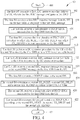
- a process 30 in Fig. 3 may be utilized in a network comprising a first BS (e.g., the BS 102) and a second BS (e.g., the BS 104), and includes the following steps:
- the first BS transmits the at least one of the first RX_NEXT (value), the first RX_DELIV (value) and the first RX_REORD (value) to the second BS in response to the DC operation procedure, in response to the second RRC response message or when/after receiving the second RRC response message.
- the first BS updates the first RX_NEXT, the first RX_DELIV and the first RX_REORD to other values (i.e., not the initial values), when processing the first plurality of PDCP Data PDUs.
- the first BS transmits all of the at least one of the first RX_NEXT (value), the first RX_DELIV (value) and the first RX_REORD (value) to the second BS.
- the first BS does not transmit one of the at least one of the first RX_NEXT (value), the first RX_DELIV (value) and the first RX_REORD (value) to the second BS.
- the first BS may not transmit the first RX_REORD to the second BS.
- the second BS may set a second RX_REORD to the first RX_NEXT, and may use the second RX_REORD to process the second plurality of PDCP SDUs.
- the first BS may not transmit the first RX_NEXT to the second BS.
- the second BS may set a second RX_NEXT to the first RX_REORD or the first RX_DELIV, and may use the second RX_NEXT to process the second plurality of PDCP SDUs.
- the first BS transmits status information of other PDCP SDU(s) associated with COUNT value(s) or PDCP sequence number (s) (SN(s)) equal to or after the first RX_DELIV to the second BS.
- the status information indicates COUNT value (s) of the other PDCP SDU(s) which are missing.
- the status information is a bitmap which indicates which PDCP SDU(s) is missing and which PDCP SDU(s) is correctly received in the receiving PDCP entity.
- a bit position of a Nth bit in the bitmap is N, i.e., the bit position of the first bit in the bitmap is 1.
- the first BS does not transmit the first RX_NEXT to the second BS.
- the second BS may set a second RX_NEXT to a COUNT value derived from the first RX_DELIV and the status information, and may use the second RX_NEXT to process the second plurality of PDCP SDUs.
- the COUNT value may be derived from a COUNT value of the last PDCP SDU of the other PDCP SDU (s) indicated in the status information.
- the COUNT value of the last PDCP SDU may be derived from the first RX_DELIV and the position of the last bit with a value of 1 in the bitmap.
- a process 40 in Fig. 4 may be utilized in a first BS (e.g., the BS 102) to communicate with a second BS (e.g., the BS 104), and includes the following steps:
- the first BS updates the first RX_NEXT, the first RX_DELIV and the first RX_REORD to other values (i.e., not initial values), when processing the first plurality of PDCP SDUs.
- the first BS transmits the COUNT value to the second BS in response to the DC operation procedure, in response to the second RRC response message or when/after receiving the second RRC response message.
- the PDCP SDU in Step 416 is a missing PDCP SDU, i.e., the first BS does not receive the PDCP SDU.
- the first BS may detect/determine the missing PDCP SDU from the first plurality of PDCP SDUs.
- the first plurality of PDCP SDUs has a first SDU and a second PDCP SDU.
- a sequence number of the first PDCP SDU is M
- a sequence number of the second PDCP SDU is N (>M).
- the PDCP SDU may be the first missing PDCP SDU.
- the second BS sets the second RX_NEXT, the second RX_DELIV and the second RX_REORD to the COUNT value.
- the first BS transmits status information of other PDCP SDU(s) to the second BS.
- the status information includes COUNT values of the other PDCP SDU(s) which are missing.
- the status information is a bitmap which indicates which PDCP SDU(s) is missing and which PDCP SDU(s) is correctly received in a PDCP entity associated to the first DRB.
- a bit position of a Nth bit in the bitmap is N, i.e., the bit position of the first bit in the bitmap is 1.
- the second BS sets the second RX_NEXT, the second RX_DELIV and the second RX_REORD according to/derived from the COUNT value of the first missing PDCP SDU and the status information.
- the second BS may set the RX_DELIV to the COUNT value.
- the second BS may set the second RX_NEXT to a COUNT value of the last missing PDCP SDU derived from the COUNT value of the first missing PDCP SDU and the status information.
- the second BS may set the second RX_NEXT to (a first COUNT value + 1), wherein the first COUNT value is a COUNT value of the last PDCP SDU received by the first BS as indicated in the status information.
- the first COUNT value may be derived from the COUNT value of the first missing PDCP SDU + the position of the last bit with a value of 1 in the bitmap.
- the second BS may set the second RX_REORD in the same way as setting the second RX_NEXT or the second RX_DELIV as described above. That is, the second RX_REORD and the second RX_NEXT are set to the same value, or the second RX_REORD and the second RX_DELIV are set to the same value.
- the first BS performs the DC operation procedure for the UE with the second BS to modify the first DRB to be the SCG bearer or the split bearer (i.e., a SCG split bearer) from a MCG bearer or a MCG split bearer.
- the split bearer i.e., a SCG split bearer
- the first RRC message configures the first DRB to be the MCG bearer.
- the second RRC message may configure the first DRB to be the SCG bearer or the split bearer from the MCG bearer.
- the second RRC message may implicitly or explicitly indicate a bearer type change from the MCG bearer to the SCG bearer or the split bearer.
- the first RRC message configures the first DRB to be a split bearer.
- the first BS configures the split bearer as the MCG split bearer.
- the second RRC message may not indicate a bearer type change for the split bearer.
- the first BS may configure the split bearer to be the MCG split bearer at the beginning, and then may configure the split bearer to be a SCG split bearer with the second BS in response to the DC operation procedure.
- the UE may or may not know that the split bearer is the MCG split bearer or the SCG split bearer.
- the UE in the DC with the first BS and the second BS transmits the second plurality of PDCP SDUs associated to the first DRB to the second BS, in response to the second RRC message or when the first DRB is modified to be the SCG bearer or the split bearer.
- the second BS starts a t-Reordering timer associated to the first DRB in response to the DC operation procedure, in response to a SN (e.g., SgNB) Reconfiguration Complete message received from the first BS or when detecting a transmission from the UE.
- the transmission may be a PDCP Data PDU (e.g., the first PDCP Data PDU associated to the first DRB when the first DRB is changed to be the SCG bearer or the split bearer), a random access (RA) preamble, a medium access control (MAC) control element (CE), a physical UL control channel (PUCCH) transmission or a physical UL shared channel (PUSCH) transmission.
- a PDCP Data PDU e.g., the first PDCP Data PDU associated to the first DRB when the first DRB is changed to be the SCG bearer or the split bearer
- RA random access
- MAC medium access control
- CE control element
- PUCCH physical UL control channel
- the first BS processes a third plurality of PDCP SDUs associated to the first DRB by using a first TX_NEXT to transmit the third plurality of PDCP SDUs to the UE.
- the first BS updates the first TX_NEXT, when processing the third plurality of PDCP SDUs to be transmitted.
- the first BS may transmit the first TX_NEXT to the second BS in response to the DC operation procedure.
- the second BS may transmit a fourth plurality of PDCP SDUs associated to the first DRB to the UE according to (e.g., by using) the first TX_NEXT.
- the first BS transmits a third RRC message on the first SRB to the UE, wherein the third RRC message configures a second DRB to be the MCG bearer.
- the first BS receives a third RRC response message from the UE on the first SRB, in response to the third RRC message.
- the first BS receives a fifth plurality of PDCP SDUs associated to the second DRB from the UE.
- the first BS processes the fifth plurality of PDCP SDUs according to (e.g., by using) a third RX_NEXT, a third RX_DELIV and a third RX_REORD which are associated to the second DRB.
- the first BS performs a DC operation procedure for the UE with the second BS to modify the second DRB to a SCG bearer or a split bearer from the MCG bearer.
- the first BS transmits a fourth RRC message on the first SRB to the UE in response to the DC operation procedure, wherein the fourth RRC message configures the second DRB to be the SCG bearer or the split bearer from the MCG bearer.
- the first BS receives a fourth RRC response message responding to the fourth RRC message on the first SRB from the UE.
- the first BS does not transmit the third RX_NEXT, the third RX_DELIV and the third RX_REORD to the second BS in response to the DC operation procedure.
- the second BS receives a sixth plurality of PDCP SDUs associated to the second DRB from the UE.
- the second BS sets (e.g., creates) a fourth RX_NEXT, a fourth RX_DELIV and a fourth RX_REORD to (with) initial values in response to the DC operation procedure.
- the second BS processes the sixth plurality of PDCP SDUs according to (e.g., by using) the fourth RX_NEXT, the fourth RX_DELIV and the fourth RX_REORD.
- the second BS sets (e.g., creates) a fourth TX_NEXT to (with) an initial value in response to the DC operation procedure.
- the second BS transmits a seventh plurality of PDCP SDUs according to (e.g., by using) the fourth TX_NEXT. If the same DC operation is performed for changing the first DRB and the second DRB from the MCG bearers to the SCG bearers or the split bearers, the second RRC message and the fourth RRC message are the same message. Otherwise, the second RRC message and the fourth RRC message are different messages.
- the first BS maintains a fifth RX_NEXT, a fifth RX_DELIV and a fifth RX_REORD associated to the first SRB for receiving the RRC messages on the first SRB.
- the first BS does not transmit the fifth RX_NEXT, the fifth RX_DELIV and the fifth RX_REORD to the second BS in response to the DC operation procedure.
- the first BS is a master evolved Node-B (eNB) or a master gNB.
- the second BS may be a secondary gNB or a secondary eNB.
- the first SRB may be a SRB1.
- the first DRB is an acknowledged mode (AM) DRB (e.g., configured to use RLC AM), and the second DRB is an unacknowledged mode (UM) DRB (e.g., configured to use RLC UM) .
- the first SRB may use the RLC AM.
- a RRC message is a RRC Reconfiguration message
- a RRC response message is a RRC Reconfiguration Complete message
- the present invention provides a method and related communication device for handling a bearer change in DC.
Landscapes
- Engineering & Computer Science (AREA)
- Computer Networks & Wireless Communication (AREA)
- Signal Processing (AREA)
- Mobile Radio Communication Systems (AREA)
Abstract
Description
- The present invention relates to a device and a method used in a wireless communication system, and more particularly, to a device and a method of handling a bearer change in dual connectivity.
- In a new radio (NR) system, a UE may communicate with a gNB in a standalone or a non-standalone mode. The UE may communicate with the gNB in dual connectivity (DC) with an evolved Node-B (eNB) or another gNB. The UE may only communicate with the gNB without the DC. A bearer may be configured to the UE in the DC. It is still unknown how to process (e.g., receive) data, if a type of the bearer is changed. Accordingly, the UE cannot operate properly. Thus, it is important to define an operation for the UE in the situation to solve the problem.
- The present invention therefore provides a method and related communication device for handling a bearer change in dual connectivity to solve the abovementioned problem.
- A network comprising a first base station (BS) and a second BS comprises at least one storage device; and at least one processing circuit coupled to the at least one storage device. The at least one storage device stores, and the at least one processing circuit is configured to execute instructions of: the first BS transmitting a first radio resource control (RRC) message on a signaling radio bearer (SRB) to a communication device, wherein the first RRC message configures a data radio bearer (DRB) ; the first BS receiving a first RRC response message from the communication device on the SRB, in response to the first RRC message; the first BS receiving a first plurality of packet data convergence protocol (PDCP) Service Data Units (SDUs) associated to the DRB from the communication device; the first BS processing the first plurality of PDCP SDUs according to a first RX_NEXT, a first RX_DELIV and a first RX_REORD which are associated to the DRB; the first BS performing a dual connectivity (DC) operation procedure for the communication device with the second BS to modify the DRB to be a secondary cell group (SCG) bearer or a split bearer; the first BS transmitting a second RRC message on the SRB to the communication device in response to the DC operation procedure; the first BS receiving a second RRC response message responding to the second RRC message on the SRB from the communication device; the first BS transmitting at least one of the first RX_NEXT, the first RX_DELIV and the first RX_REORD to the second BS; the second BS receiving a second plurality of PDCP SDUs associated to the DRB from the communication device; and the second BS processing the second plurality of PDCP SDUs according to the at least one of the first RX_NEXT, the first RX_DELIV and the first RX_REORD.
- These and other objectives of the present invention will no doubt become obvious to those of ordinary skill in the art after reading the following detailed description of the preferred embodiment that is illustrated in the various figures and drawings.
-
-
Fig. 1 is a schematic diagram of a wireless communication system according to an example of the present invention. -
Fig. 2 is a schematic diagram of a communication device according to an example of the present invention. -
Fig. 3 is a flowchart of a process according to an example of the present invention. -
Fig. 4 is a flowchart of a process according to an example of the present invention. -
Fig. 1 is a schematic diagram of awireless communication system 10 according to an example of the present invention. Thewireless communication system 10 is briefly composed of acommunication device 100, a base station (BS) 102 and aBS 104. InFig. 1 , thecommunication device 100, theBS 102 and theBS 104 are simply utilized for illustrating the structure of thewireless communication system 10. - The
communication device 100 may be configured to communicate with theBS 102 only, i.e., not in dual connectivity (DC). The BS 102 may command thecommunication device 100 to hand over to theBS 104. - The
communication device 100 may be configured to communicate with theBSs communication device 100. In one example, thecommunication device 100 receives protocol data units (PDUs) from theBS 102 at one carrier frequency and theBS 104 at another carrier frequency, or thecommunication device 100 transmits PDUs to theBS 102 at one carrier frequency and/or theBS 104 at another carrier frequency. In one example, thecommunication device 100 receives PDUs from at least one cell of theBS 102 and/or at least one cell of theBS 104. Similarly, thecommunication device 100 transmits the PDUs to at least one cell of theBS 102 and/or at least one cell of theBS 104. For the UE in the DC with theBSs BSs - The
communication device 100 may be a user equipment (UE), a mobile phone, a laptop, a tablet computer, an electronic book, a portable computer system, a vehicle or an airplane. In addition, for an uplink (UL), thecommunication device 100 is a transmitter and the BS (s) 102 and/or 104 are/is a receiver (s), and for a downlink (DL), the BS(s) 102 and/or 104 are/is a transmitter(s) and thecommunication device 100 is a receiver. -
Fig. 2 is a schematic diagram of acommunication device 20 according to an example of the present invention. Thecommunication device 20 may be thecommunication device 100, the BS (s) 102 and/or 104 shown inFig. 1 , but is not limited herein. Thecommunication device 20 may include at least oneprocessing circuit 200 such as a microprocessor or Application Specific Integrated Circuit (ASIC), at least onestorage device 210 and at least onecommunication interfacing device 220. The at least onestorage device 210 may be any data storage device that may storeprogram codes 214, accessed and executed by the at least oneprocessing circuit 200. Examples of the at least onestorage device 210 include but are not limited to a subscriber identity module (SIM), read-only memory (ROM), flash memory, random-access memory (RAM), hard disk, optical data storage device, non-volatile storage device, non-transitory computer-readable medium (e.g., tangible media), etc. The at least onecommunication interfacing device 220 is preferably at least one transceiver and is used to transmit and receive signals (e.g., data, messages and/or packets) according to processing results of the at least oneprocessing circuit 200. - In the following examples, a UE is used for representing the
communication device 100 inFig. 1 , to simplify the illustration of the examples. - In one example, the UE connecting to the MN has a first signalling radio bearer (SRB), and the MN transmits a measurement configuration on the first SRB to the UE. In detail, the UE transmits a measurement report on the first SRB to the MN according to the measurement configuration. The MN initiates a SN Addition procedure (e.g., SgNB Addition procedure) with the SN for the UE in response to the measurement report. The MN configures the UE to connect to the SN in response to the SN Addition procedure by transmitting a radio resource control (RRC) message on the first SRB to the UE. The RRC message includes a SN configuration (e.g., SCG configuration) for the UE to connect to the SN. According to the RRC message, the UE may setup a radio bearer (RB).
- A protocol architecture may be used for illustrating that a use of a RB depends on how the RB is setup. A RB may be a data RB (DRB) for data transmission and/or data reception on a user plane, and a SRB for data transmission and/or data reception on a control plane. A DRB configuration may include at least one of a DRB identity, a packet data convergence protocol (PDCP) configuration, a radio link control (RLC) configuration, a logical channel identity and a logical channel configuration (e.g., priority and/or logical channel group). A SRB configuration may include a SRB identity, the RLC configuration and the logical channel configuration. In the DC, there may be three types of RB: a master cell group (MCG) bearer, a secondary cell group (SCG) bearer and a split bearer. The MCG bearer may utilize radio protocol(s) located at the MN, to use radio resources (e.g., time resources and/or frequency resources) of the MN. The SCG bearer may utilize radio protocol (s) located at the SN, to use radio resources (e.g., time resources and/or frequency resources) of the SN. The split bearer may utilize the radio protocol(s) located at both the MN and the SN, to use the radio resources of the MN and the SN. The split bearer may be a MCG split bearer or a SCG split bearer. A DRB may be the MCG bearer, the SCG bearer or the split bearer. A SRB may be configured as the MCG bearer or the split bearer.
- In one example, a BS (e.g., the
BS 102 or the BS 104) may use the following state variables to communicate PDCP Service Data Units (SDUs) associated to a DRB or a SRB with a communication device (e.g., the communication device 100). - TX_NEXT, which indicates a COUNT value of a next PDCP SDU to be transmitted. The initial value of TX_NEXT is 0.
- RX_NEXT, which indicates a COUNT value of a next PDCP SDU expected to be received. The initial value of RX_NEXT is 0.
- RX_DELIV, which indicates a COUNT value of a first PDCP SDU not delivered to upper layers, but still waited for. The initial value of RX_DELIV is 0.
- RX_REORD, which indicates a COUNT value following a COUNT value associated with a PDCP Data PDU which triggered/triggers t-Reordering to be started or restarted.
- A
process 30 inFig. 3 may be utilized in a network comprising a first BS (e.g., the BS 102) and a second BS (e.g., the BS 104), and includes the following steps: - Step 300:
- Start.
- Step 302:
- The first BS transmits a first RRC message on a first SRB to a UE, wherein the first RRC message configures a first DRB.
- Step 304:
- The first BS receives a first RRC response message from the UE on the first SRB, in response to the first RRC message.
- Step 306:
- The first BS receives a first plurality of PDCP SDUs associated to the first DRB from the UE.
- Step 308:
- The first BS processes the first plurality of PDCP SDUs according to (e.g., by using) a first RX_NEXT, a first RX_DELIV and a first RX_REORD which are associated to the first DRB.
- Step 310:
- The first BS performs a DC operation procedure for the UE with the second BS to modify the first DRB to be a SCG bearer or a split bearer.
- Step 312:
- The first BS transmits a second RRC message on the first SRB to the UE in response to the DC operation procedure.
- Step 314:
- The first BS receives a second RRC response message responding to the second RRC message on the first SRB from the UE.
- Step 316:
- The first BS transmits at least one of the first RX_NEXT, the first RX_DELIV and the first RX_REORD to the second BS.
- Step 318:
- The second BS receives a second plurality of PDCP SDUs associated to the first DRB from the UE.
- Step 320:
- The second BS processes the second plurality of PDCP SDUs according to (e.g., by using) the at least one of the first RX_NEXT, the first RX_DELIV and the first RX_REORD.
- Step 322:
- End.
- In one example, the first BS transmits the at least one of the first RX_NEXT (value), the first RX_DELIV (value) and the first RX_REORD (value) to the second BS in response to the DC operation procedure, in response to the second RRC response message or when/after receiving the second RRC response message.
- In one example, the first BS updates the first RX_NEXT, the first RX_DELIV and the first RX_REORD to other values (i.e., not the initial values), when processing the first plurality of PDCP Data PDUs.
- In one example, the first BS transmits all of the at least one of the first RX_NEXT (value), the first RX_DELIV (value) and the first RX_REORD (value) to the second BS.
- In one example, the first BS does not transmit one of the at least one of the first RX_NEXT (value), the first RX_DELIV (value) and the first RX_REORD (value) to the second BS. For example, the first BS may not transmit the first RX_REORD to the second BS. In this case, the second BS may set a second RX_REORD to the first RX_NEXT, and may use the second RX_REORD to process the second plurality of PDCP SDUs. For example, the first BS may not transmit the first RX_NEXT to the second BS. The second BS may set a second RX_NEXT to the first RX_REORD or the first RX_DELIV, and may use the second RX_NEXT to process the second plurality of PDCP SDUs.
- In one example, the first BS transmits status information of other PDCP SDU(s) associated with COUNT value(s) or PDCP sequence number (s) (SN(s)) equal to or after the first RX_DELIV to the second BS. In one example, the status information indicates COUNT value (s) of the other PDCP SDU(s) which are missing. In one example, the status information is a bitmap which indicates which PDCP SDU(s) is missing and which PDCP SDU(s) is correctly received in the receiving PDCP entity. A bit position of a Nth bit in the bitmap is N, i.e., the bit position of the first bit in the bitmap is 1.
- In one example, the first BS does not transmit the first RX_NEXT to the second BS. The second BS may set a second RX_NEXT to a COUNT value derived from the first RX_DELIV and the status information, and may use the second RX_NEXT to process the second plurality of PDCP SDUs. The COUNT value may be derived from a COUNT value of the last PDCP SDU of the other PDCP SDU (s) indicated in the status information. For example, the COUNT value of the last PDCP SDU may be derived from the first RX_DELIV and the position of the last bit with a value of 1 in the bitmap.
- A
process 40 inFig. 4 may be utilized in a first BS (e.g., the BS 102) to communicate with a second BS (e.g., the BS 104), and includes the following steps: - Step 400:
- Start.
- Steps 402-414:
- The same as Steps 302-314.
- Step 416:
- The first BS transmits a COUNT value (e.g., of a PDCP SDU) to the second BS.
- Step 418:
- The second BS determines a second RX_NEXT, a second RX_DELIV and a second RX_REORD associated to the first DRB according to the COUNT value.
- Step 420:
- The second BS receives a second plurality of PDCP SDUs associated to the first DRB from the UE.
- Step 422:
- The second BS processes the second plurality of PDCP SDUs according to (e.g., by using) the second RX_NEXT, the second RX_DELIV and the second RX_REORD.
- Step 424:
- End.
- In one example, the first BS updates the first RX_NEXT, the first RX_DELIV and the first RX_REORD to other values (i.e., not initial values), when processing the first plurality of PDCP SDUs.
- In one example, the first BS transmits the COUNT value to the second BS in response to the DC operation procedure, in response to the second RRC response message or when/after receiving the second RRC response message.
- In one example, the PDCP SDU in
Step 416 is a missing PDCP SDU, i.e., the first BS does not receive the PDCP SDU. The first BS may detect/determine the missing PDCP SDU from the first plurality of PDCP SDUs. For example, the first plurality of PDCP SDUs has a first SDU and a second PDCP SDU. A sequence number of the first PDCP SDU is M, and a sequence number of the second PDCP SDU is N (>M). Then, the first BS detects/determines the missing PDCP SDU which is a PDCP SDU with a sequence number = M+1, ... or N-1, since the UE does not receive the PDCP SDU(s) which has the sequence number = M+1, ..., N-1. The PDCP SDU may be the first missing PDCP SDU. - In one example, the second BS sets the second RX_NEXT, the second RX_DELIV and the second RX_REORD to the COUNT value.
- In one example, the first BS transmits status information of other PDCP SDU(s) to the second BS. In one example, the status information includes COUNT values of the other PDCP SDU(s) which are missing. In one example, the status information is a bitmap which indicates which PDCP SDU(s) is missing and which PDCP SDU(s) is correctly received in a PDCP entity associated to the first DRB. A bit position of a Nth bit in the bitmap is N, i.e., the bit position of the first bit in the bitmap is 1.
- In one example, the second BS sets the second RX_NEXT, the second RX_DELIV and the second RX_REORD according to/derived from the COUNT value of the first missing PDCP SDU and the status information. For example, the second BS may set the RX_DELIV to the COUNT value. For example, the second BS may set the second RX_NEXT to a COUNT value of the last missing PDCP SDU derived from the COUNT value of the first missing PDCP SDU and the status information. For example, the second BS may set the second RX_NEXT to (a first COUNT value + 1), wherein the first COUNT value is a COUNT value of the last PDCP SDU received by the first BS as indicated in the status information. For example, the first COUNT value may be derived from the COUNT value of the first missing PDCP SDU + the position of the last bit with a value of 1 in the bitmap. The second BS may set the second RX_REORD in the same way as setting the second RX_NEXT or the second RX_DELIV as described above. That is, the second RX_REORD and the second RX_NEXT are set to the same value, or the second RX_REORD and the second RX_DELIV are set to the same value.
- The following examples may be applied to the
processes - In one example, the first BS performs the DC operation procedure for the UE with the second BS to modify the first DRB to be the SCG bearer or the split bearer (i.e., a SCG split bearer) from a MCG bearer or a MCG split bearer.
- In one example, the first RRC message configures the first DRB to be the MCG bearer. The second RRC message may configure the first DRB to be the SCG bearer or the split bearer from the MCG bearer. The second RRC message may implicitly or explicitly indicate a bearer type change from the MCG bearer to the SCG bearer or the split bearer.
- In one example, the first RRC message configures the first DRB to be a split bearer. The first BS configures the split bearer as the MCG split bearer. The second RRC message may not indicate a bearer type change for the split bearer. In this case, the first BS may configure the split bearer to be the MCG split bearer at the beginning, and then may configure the split bearer to be a SCG split bearer with the second BS in response to the DC operation procedure. The UE may or may not know that the split bearer is the MCG split bearer or the SCG split bearer.
- In one example, the UE in the DC with the first BS and the second BS transmits the second plurality of PDCP SDUs associated to the first DRB to the second BS, in response to the second RRC message or when the first DRB is modified to be the SCG bearer or the split bearer.
- In one example, the second BS starts a t-Reordering timer associated to the first DRB in response to the DC operation procedure, in response to a SN (e.g., SgNB) Reconfiguration Complete message received from the first BS or when detecting a transmission from the UE. The transmission may be a PDCP Data PDU (e.g., the first PDCP Data PDU associated to the first DRB when the first DRB is changed to be the SCG bearer or the split bearer), a random access (RA) preamble, a medium access control (MAC) control element (CE), a physical UL control channel (PUCCH) transmission or a physical UL shared channel (PUSCH) transmission.
- In one example, the first BS processes a third plurality of PDCP SDUs associated to the first DRB by using a first TX_NEXT to transmit the third plurality of PDCP SDUs to the UE. The first BS updates the first TX_NEXT, when processing the third plurality of PDCP SDUs to be transmitted. Then, the first BS may transmit the first TX_NEXT to the second BS in response to the DC operation procedure. The second BS may transmit a fourth plurality of PDCP SDUs associated to the first DRB to the UE according to (e.g., by using) the first TX_NEXT.
- In one example, the first BS transmits a third RRC message on the first SRB to the UE, wherein the third RRC message configures a second DRB to be the MCG bearer. The first BS receives a third RRC response message from the UE on the first SRB, in response to the third RRC message. The first BS receives a fifth plurality of PDCP SDUs associated to the second DRB from the UE. The first BS processes the fifth plurality of PDCP SDUs according to (e.g., by using) a third RX_NEXT, a third RX_DELIV and a third RX_REORD which are associated to the second DRB. The first BS performs a DC operation procedure for the UE with the second BS to modify the second DRB to a SCG bearer or a split bearer from the MCG bearer. The first BS transmits a fourth RRC message on the first SRB to the UE in response to the DC operation procedure, wherein the fourth RRC message configures the second DRB to be the SCG bearer or the split bearer from the MCG bearer. The first BS receives a fourth RRC response message responding to the fourth RRC message on the first SRB from the UE. The first BS does not transmit the third RX_NEXT, the third RX_DELIV and the third RX_REORD to the second BS in response to the DC operation procedure. The second BS receives a sixth plurality of PDCP SDUs associated to the second DRB from the UE. The second BS sets (e.g., creates) a fourth RX_NEXT, a fourth RX_DELIV and a fourth RX_REORD to (with) initial values in response to the DC operation procedure. The second BS processes the sixth plurality of PDCP SDUs according to (e.g., by using) the fourth RX_NEXT, the fourth RX_DELIV and the fourth RX_REORD. The second BS sets (e.g., creates) a fourth TX_NEXT to (with) an initial value in response to the DC operation procedure. The second BS transmits a seventh plurality of PDCP SDUs according to (e.g., by using) the fourth TX_NEXT. If the same DC operation is performed for changing the first DRB and the second DRB from the MCG bearers to the SCG bearers or the split bearers, the second RRC message and the fourth RRC message are the same message. Otherwise, the second RRC message and the fourth RRC message are different messages.
- In one example, the first BS maintains a fifth RX_NEXT, a fifth RX_DELIV and a fifth RX_REORD associated to the first SRB for receiving the RRC messages on the first SRB. The first BS does not transmit the fifth RX_NEXT, the fifth RX_DELIV and the fifth RX_REORD to the second BS in response to the DC operation procedure.
- In one example, the first BS is a master evolved Node-B (eNB) or a master gNB. The second BS may be a secondary gNB or a secondary eNB. The first SRB may be a SRB1.
- In one example, the first DRB is an acknowledged mode (AM) DRB (e.g., configured to use RLC AM), and the second DRB is an unacknowledged mode (UM) DRB (e.g., configured to use RLC UM) . The first SRB may use the RLC AM.
- In one example, a RRC message is a RRC Reconfiguration message, and a RRC response message is a RRC Reconfiguration Complete message.
- It should be noted that although the above examples are illustrated to clarify the related operations of corresponding processes. The examples can be combined and/or modified arbitrarily according to system requirements and/or design considerations.
- Those skilled in the art should readily make combinations, modifications and/or alterations on the abovementioned description and examples. The abovementioned description, steps and/or processes including suggested steps can be realized by means that could be hardware, software, firmware (known as a combination of a hardware device and computer instructions and data that reside as read-only software on the hardware device), an electronic system, or combination thereof. An example of the means may be the
communication device 20. - To sum up, the present invention provides a method and related communication device for handling a bearer change in DC.
Those skilled in the art will readily observe that numerous modifications and alterations of the device and method may be made while retaining the teachings of the invention. Accordingly, the above disclosure should be construed as limited only by the metes and bounds of the appended claims.
Claims (10)
- A network comprising a first base station (BS) and a second BS, comprising:at least one storage device; andat least one processing circuit, coupled to the at least one storage device, wherein the at least one storage device stores, and the at least one processing circuit is configured to execute instructions of:the first BS transmitting a first radio resource control (RRC) message on a signaling radio bearer (SRB) to a communication device, wherein the first RRC message configures a data radio bearer (DRB);the first BS receiving a first RRC response message from the communication device on the SRB, in response to the first RRC message;the first BS receiving a first plurality of packet data convergence protocol (PDCP) Service Data Units (SDUs) associated to the DRB from the communication device;the first BS processing the first plurality of PDCP SDUs according to a first RX_NEXT, a first RX_DELIV and a first RX_REORD which are associated to the DRB;the first BS performing a dual connectivity (DC) operation procedure for the communication device with the second BS to modify the DRB to be a secondary cell group (SCG) bearer or a split bearer;the first BS transmitting a second RRC message on the SRB to the communication device in response to the DC operation procedure;the first BS receiving a second RRC response message responding to the second RRC message on the SRB from the communication device;the first BS transmitting at least one of the first RX_NEXT, the first RX_DELIV and the first RX_REORD to the second BS;the second BS receiving a second plurality of PDCP SDUs associated to the DRB from the communication device; andthe second BS processing the second plurality of PDCP SDUs according to the at least one of the first RX_NEXT, the first RX_DELIV and the first RX_REORD.
- The network of claim 1, wherein the first BS transmits the at least one of the first RX_NEXT, the first RX_DELIV and the first RX_REORD to the second BS in response to the DC operation procedure, or in response to the second RRC response message.
- The network of claim 1, wherein the instructions further comprise:
the first BS transmitting status information of at least one other PDCP SDU associated with at least one COUNT value or at least one PDCP sequence number equal to or after the first RX_DELIV, to the second BS. - The network of claim 3, wherein the instructions further comprise:the second BS setting a second RX_NEXT to a COUNT value derived from the first RX_DELIV and the status information; andthe second BS using the second RX_NEXT to process the second plurality of PDCP SDUs.
- The network of claim 1, wherein the instructions further comprise:
the second BS starting a t-Reordering timer associated to the DRB in response to the DC operation procedure, in response to a secondary node (SN) Reconfiguration Complete message received from the first BS, or when detecting a transmission from the communication device. - A network comprising a first base station (BS) and a second BS, comprising:at least one storage device; andat least one processing circuit, coupled to the at least one storage device, wherein the at least one storage device stores, and the at least one processing circuit is configured to execute instructions of:the first BS transmitting a first radio resource control (RRC) message on a signaling radio bearer (SRB) to a communication device, wherein the first RRC message configures a data radio bearer (DRB);the first BS receiving a first RRC response message from the communication device on the SRB, in response to the first RRC message;the first BS receiving a first plurality of packet data convergence protocol (PDCP) Service Data Units (SDUs) associated to the DRB from the communication device;the first BS processing the first plurality of PDCP SDUs according to a first RX_NEXT, a first RX_DELIV and a first RX_REORD which are associated to the DRB;the first BS performing a dual connectivity (DC) operation procedure for the communication device with the second BS to modify the DRB to be a secondary cell group (SCG) bearer or a split bearer;the first BS transmitting a second RRC message on the SRB to the communication device in response to the DC operation procedure;the first BS receiving a second RRC response message responding to the second RRC message on the SRB from the communication device;the first BS transmitting a COUNT value to the second BS;the second BS determining a second RX_NEXT, a second RX_DELIV and a second RX_REORD according to the COUNT value;the second BS receiving a second plurality of PDCP SDUs associated to the DRB from the communication device; andthe second BS processing the second plurality of PDCP SDUs according to the second RX_NEXT, the second RX_DELIV and the second RX_REORD.
- The network of claim 6, wherein the instructions further comprise:
the first BS updating the first RX_NEXT, the first RX_DELIV and the first RX_REORD to a plurality of other values, when processing the first plurality of PDCP SDUs. - The network of claim 6, wherein the first BS transmits the COUNT value to the second BS in response to the DC operation procedure, or in response to the second RRC response message.
- The network of claim 6, wherein the second BS sets the second RX_NEXT to the COUNT value, the second RX_DELIV to the COUNT value and the second RX_REORD to the COUNT value.
- The network of claim 6, wherein the instructions further comprise:the first BS transmitting status information of at least one other PDCP SDU; andthe second BS setting the second RX_NEXT, the second RX_DELIV and the second RX_REORD according to the COUNT value and the status information.
Applications Claiming Priority (2)
| Application Number | Priority Date | Filing Date | Title |
|---|---|---|---|
| US201762544001P | 2017-08-11 | 2017-08-11 | |
| US201762566323P | 2017-09-30 | 2017-09-30 |
Publications (2)
| Publication Number | Publication Date |
|---|---|
| EP3442267A1 true EP3442267A1 (en) | 2019-02-13 |
| EP3442267B1 EP3442267B1 (en) | 2021-07-07 |
Family
ID=63244422
Family Applications (1)
| Application Number | Title | Priority Date | Filing Date |
|---|---|---|---|
| EP18188527.8A Active EP3442267B1 (en) | 2017-08-11 | 2018-08-10 | Network for handling a bearer change in dual connectivity |
Country Status (4)
| Country | Link |
|---|---|
| US (1) | US10512006B2 (en) |
| EP (1) | EP3442267B1 (en) |
| CN (1) | CN109392197B (en) |
| TW (1) | TWI674024B (en) |
Families Citing this family (4)
| Publication number | Priority date | Publication date | Assignee | Title |
|---|---|---|---|---|
| US11184821B2 (en) * | 2018-08-09 | 2021-11-23 | Qualcomm Incorporated | Inter-system handover between standalone mode and non-standalone mode |
| US11963024B2 (en) * | 2019-02-15 | 2024-04-16 | Lg Electronics Inc. | Method and apparatus for backhaul status reporting in wireless communication system |
| CN114902729B (en) * | 2020-02-13 | 2024-02-02 | Lg 电子株式会社 | Method and device for sending response messages in wireless communication system |
| CN113556776B (en) * | 2020-04-23 | 2024-11-15 | 华为技术有限公司 | Communication method and device for sending experience quality measurement results |
Citations (4)
| Publication number | Priority date | Publication date | Assignee | Title |
|---|---|---|---|---|
| EP2835925A1 (en) * | 2013-08-09 | 2015-02-11 | Panasonic Intellectual Property Corporation of America | Efficient Status Reporting for UEs in dual connectivity during mobility |
| WO2015065080A1 (en) * | 2013-11-01 | 2015-05-07 | Samsung Electronics Co., Ltd. | Method and apparatus for reconfiguring a bearer |
| WO2015145255A2 (en) * | 2014-03-28 | 2015-10-01 | Alcatel Lucent | Method and apparatus for processing rlc/ pdcp entities at a user equipment in a dual connectivity system |
| GB2528913A (en) * | 2014-08-04 | 2016-02-10 | Samsung Electronics Co Ltd | Signalling in dual connectivity mobile communication networks |
Family Cites Families (7)
| Publication number | Priority date | Publication date | Assignee | Title |
|---|---|---|---|---|
| US20150043492A1 (en) * | 2013-08-12 | 2015-02-12 | Electronics And Telecommunications Research Institute | Method for providing dual connectivity in wireless communication system |
| KR102157798B1 (en) * | 2013-10-29 | 2020-09-18 | 삼성전자 주식회사 | Method and apparatus for transmitting and receiving a data using a plurality of carriers in mobilre communication system |
| US10004098B2 (en) * | 2014-01-29 | 2018-06-19 | Samsung Electronics Co., Ltd. | Method and apparatus for transmitting and receiving data using a plurality of carriers in mobile communication system |
| JP2015177548A (en) * | 2014-03-14 | 2015-10-05 | 宏達國際電子股▲ふん▼有限公司 | Connection change method applicable to user equipment and base station |
| US9743319B2 (en) * | 2014-11-12 | 2017-08-22 | Htc Corporation | Device and method of handling network configurations |
| EP3051916B1 (en) * | 2015-01-21 | 2020-11-04 | HTC Corporation | Device and method of handling communication operation with multiple base stations |
| KR102772269B1 (en) * | 2017-02-03 | 2025-02-25 | 삼성전자 주식회사 | Method and apparatus for processing a security key in a handover using multiple connections in a mobile communication system |
-
2018
- 2018-08-09 US US16/059,068 patent/US10512006B2/en active Active
- 2018-08-10 TW TW107128010A patent/TWI674024B/en active
- 2018-08-10 CN CN201810910423.5A patent/CN109392197B/en active Active
- 2018-08-10 EP EP18188527.8A patent/EP3442267B1/en active Active
Patent Citations (4)
| Publication number | Priority date | Publication date | Assignee | Title |
|---|---|---|---|---|
| EP2835925A1 (en) * | 2013-08-09 | 2015-02-11 | Panasonic Intellectual Property Corporation of America | Efficient Status Reporting for UEs in dual connectivity during mobility |
| WO2015065080A1 (en) * | 2013-11-01 | 2015-05-07 | Samsung Electronics Co., Ltd. | Method and apparatus for reconfiguring a bearer |
| WO2015145255A2 (en) * | 2014-03-28 | 2015-10-01 | Alcatel Lucent | Method and apparatus for processing rlc/ pdcp entities at a user equipment in a dual connectivity system |
| GB2528913A (en) * | 2014-08-04 | 2016-02-10 | Samsung Electronics Co Ltd | Signalling in dual connectivity mobile communication networks |
Non-Patent Citations (4)
| Title |
|---|
| "3rd Generation Partnership Project; Technical Specification Group Radio Access Network; Evolved Universal Terrestrial Radio Access (E-UTRA) and NR; Multi-connectivity; Stage 2 (Release 15)", 3GPP STANDARD ; TECHNICAL SPECIFICATION ; TS 37.340, vol. RAN WG2, no. V0.2.1, 9 August 2017 (2017-08-09), pages 1 - 43, XP051336704 * |
| "3rd Generation Partnership Project; Technical Specification Group Radio Access Network; NR; Packet Data Convergence Protocol (PDCP) specification (Release 15)", 3GPP STANDARD; TECHNICAL SPECIFICATION; TS 38.323, vol. RAN WG2, no. V0.2.0, 19 July 2017 (2017-07-19), pages 1 - 27, XP051450225 * |
| ERICSSON: "PDCP reception algorithm", vol. RAN WG2, no. Qingdao; 20170627 - 20170629, 26 June 2017 (2017-06-26), XP051301647, Retrieved from the Internet <URL:http://www.3gpp.org/ftp/Meetings_3GPP_SYNC/RAN2/Docs/> [retrieved on 20170626] * |
| HUAWEI (RAPPORTEUR): "Summary of [97bis#12][NR] Bearer type change (Huawei)", vol. RAN WG2, no. Qingdao, China; 20170627 - 20170629, 26 June 2017 (2017-06-26), XP051301892, Retrieved from the Internet <URL:http://www.3gpp.org/ftp/Meetings_3GPP_SYNC/RAN2/Docs/> [retrieved on 20170626] * |
Also Published As
| Publication number | Publication date |
|---|---|
| CN109392197B (en) | 2022-10-21 |
| EP3442267B1 (en) | 2021-07-07 |
| TWI674024B (en) | 2019-10-01 |
| TW201911941A (en) | 2019-03-16 |
| CN109392197A (en) | 2019-02-26 |
| US10512006B2 (en) | 2019-12-17 |
| US20190053111A1 (en) | 2019-02-14 |
Similar Documents
| Publication | Publication Date | Title |
|---|---|---|
| US10687365B2 (en) | Device and method of handling bandwidth parts | |
| US10448447B2 (en) | Device and method for handling a bearer type change for a radio bearer | |
| EP3413625A1 (en) | Method of handling secondary cell group configuration in secondary node change | |
| US10856356B2 (en) | Device and method of handling a secondary node configuration | |
| US10582556B2 (en) | Device and method for handling a bearer type change | |
| US10531508B2 (en) | Device and method of handling carrier aggregation and dual connectivity | |
| US10873985B2 (en) | Device and method of handling a dual connectivity with base stations | |
| US10512006B2 (en) | Device and method of handling a bearer change in dual connectivity | |
| US10462695B2 (en) | Device and method for handling measurement configuration in dual connectivity | |
| US10736161B2 (en) | Device and method for handling measurement configuration and signaling radio bearer | |
| US10548176B2 (en) | Device and method of handling dual connectivity | |
| US10531359B2 (en) | Device and method for handling a packet data convergence protocol operation | |
| EP3442266A1 (en) | Device and method of handling a secondary node change in dual connectivity | |
| EP3442181A1 (en) | Device and method of handling a handover | |
| US10624151B2 (en) | Device and method of handling a signalling radio bearer configuration | |
| EP3373694A1 (en) | Device for handling communications in a dual connectivity | |
| EP3442264A1 (en) | Device and method of handling a bearer change in dual connectivity |
Legal Events
| Date | Code | Title | Description |
|---|---|---|---|
| PUAI | Public reference made under article 153(3) epc to a published international application that has entered the european phase |
Free format text: ORIGINAL CODE: 0009012 |
|
| STAA | Information on the status of an ep patent application or granted ep patent |
Free format text: STATUS: EXAMINATION IS IN PROGRESS |
|
| 17P | Request for examination filed |
Effective date: 20180810 |
|
| AK | Designated contracting states |
Kind code of ref document: A1 Designated state(s): AL AT BE BG CH CY CZ DE DK EE ES FI FR GB GR HR HU IE IS IT LI LT LU LV MC MK MT NL NO PL PT RO RS SE SI SK SM TR |
|
| AX | Request for extension of the european patent |
Extension state: BA ME |
|
| RBV | Designated contracting states (corrected) |
Designated state(s): AL AT BE BG CH CY CZ DE DK EE ES FI FR GB GR HR HU IE IS IT LI LT LU LV MC MK MT NL NO PL PT RO RS SE SI SK SM TR |
|
| RIC1 | Information provided on ipc code assigned before grant |
Ipc: H04W 76/15 20180101ALI20201118BHEP Ipc: H04W 36/00 20090101AFI20201118BHEP |
|
| GRAP | Despatch of communication of intention to grant a patent |
Free format text: ORIGINAL CODE: EPIDOSNIGR1 |
|
| STAA | Information on the status of an ep patent application or granted ep patent |
Free format text: STATUS: GRANT OF PATENT IS INTENDED |
|
| INTG | Intention to grant announced |
Effective date: 20210208 |
|
| GRAS | Grant fee paid |
Free format text: ORIGINAL CODE: EPIDOSNIGR3 |
|
| GRAA | (expected) grant |
Free format text: ORIGINAL CODE: 0009210 |
|
| STAA | Information on the status of an ep patent application or granted ep patent |
Free format text: STATUS: THE PATENT HAS BEEN GRANTED |
|
| AK | Designated contracting states |
Kind code of ref document: B1 Designated state(s): AL AT BE BG CH CY CZ DE DK EE ES FI FR GB GR HR HU IE IS IT LI LT LU LV MC MK MT NL NO PL PT RO RS SE SI SK SM TR |
|
| REG | Reference to a national code |
Ref country code: GB Ref legal event code: FG4D |
|
| REG | Reference to a national code |
Ref country code: AT Ref legal event code: REF Ref document number: 1409813 Country of ref document: AT Kind code of ref document: T Effective date: 20210715 |
|
| REG | Reference to a national code |
Ref country code: DE Ref legal event code: R096 Ref document number: 602018019592 Country of ref document: DE |
|
| REG | Reference to a national code |
Ref country code: IE Ref legal event code: FG4D |
|
| REG | Reference to a national code |
Ref country code: NL Ref legal event code: FP |
|
| REG | Reference to a national code |
Ref country code: LT Ref legal event code: MG9D |
|
| REG | Reference to a national code |
Ref country code: AT Ref legal event code: MK05 Ref document number: 1409813 Country of ref document: AT Kind code of ref document: T Effective date: 20210707 |
|
| PG25 | Lapsed in a contracting state [announced via postgrant information from national office to epo] |
Ref country code: AT Free format text: LAPSE BECAUSE OF FAILURE TO SUBMIT A TRANSLATION OF THE DESCRIPTION OR TO PAY THE FEE WITHIN THE PRESCRIBED TIME-LIMIT Effective date: 20210707 Ref country code: BG Free format text: LAPSE BECAUSE OF FAILURE TO SUBMIT A TRANSLATION OF THE DESCRIPTION OR TO PAY THE FEE WITHIN THE PRESCRIBED TIME-LIMIT Effective date: 20211007 Ref country code: LT Free format text: LAPSE BECAUSE OF FAILURE TO SUBMIT A TRANSLATION OF THE DESCRIPTION OR TO PAY THE FEE WITHIN THE PRESCRIBED TIME-LIMIT Effective date: 20210707 Ref country code: PT Free format text: LAPSE BECAUSE OF FAILURE TO SUBMIT A TRANSLATION OF THE DESCRIPTION OR TO PAY THE FEE WITHIN THE PRESCRIBED TIME-LIMIT Effective date: 20211108 Ref country code: NO Free format text: LAPSE BECAUSE OF FAILURE TO SUBMIT A TRANSLATION OF THE DESCRIPTION OR TO PAY THE FEE WITHIN THE PRESCRIBED TIME-LIMIT Effective date: 20211007 Ref country code: FI Free format text: LAPSE BECAUSE OF FAILURE TO SUBMIT A TRANSLATION OF THE DESCRIPTION OR TO PAY THE FEE WITHIN THE PRESCRIBED TIME-LIMIT Effective date: 20210707 Ref country code: ES Free format text: LAPSE BECAUSE OF FAILURE TO SUBMIT A TRANSLATION OF THE DESCRIPTION OR TO PAY THE FEE WITHIN THE PRESCRIBED TIME-LIMIT Effective date: 20210707 Ref country code: HR Free format text: LAPSE BECAUSE OF FAILURE TO SUBMIT A TRANSLATION OF THE DESCRIPTION OR TO PAY THE FEE WITHIN THE PRESCRIBED TIME-LIMIT Effective date: 20210707 Ref country code: RS Free format text: LAPSE BECAUSE OF FAILURE TO SUBMIT A TRANSLATION OF THE DESCRIPTION OR TO PAY THE FEE WITHIN THE PRESCRIBED TIME-LIMIT Effective date: 20210707 Ref country code: SE Free format text: LAPSE BECAUSE OF FAILURE TO SUBMIT A TRANSLATION OF THE DESCRIPTION OR TO PAY THE FEE WITHIN THE PRESCRIBED TIME-LIMIT Effective date: 20210707 |
|
| PG25 | Lapsed in a contracting state [announced via postgrant information from national office to epo] |
Ref country code: PL Free format text: LAPSE BECAUSE OF FAILURE TO SUBMIT A TRANSLATION OF THE DESCRIPTION OR TO PAY THE FEE WITHIN THE PRESCRIBED TIME-LIMIT Effective date: 20210707 Ref country code: LV Free format text: LAPSE BECAUSE OF FAILURE TO SUBMIT A TRANSLATION OF THE DESCRIPTION OR TO PAY THE FEE WITHIN THE PRESCRIBED TIME-LIMIT Effective date: 20210707 Ref country code: GR Free format text: LAPSE BECAUSE OF FAILURE TO SUBMIT A TRANSLATION OF THE DESCRIPTION OR TO PAY THE FEE WITHIN THE PRESCRIBED TIME-LIMIT Effective date: 20211008 |
|
| REG | Reference to a national code |
Ref country code: CH Ref legal event code: PL |
|
| REG | Reference to a national code |
Ref country code: DE Ref legal event code: R097 Ref document number: 602018019592 Country of ref document: DE |
|
| REG | Reference to a national code |
Ref country code: BE Ref legal event code: MM Effective date: 20210831 |
|
| PG25 | Lapsed in a contracting state [announced via postgrant information from national office to epo] |
Ref country code: LI Free format text: LAPSE BECAUSE OF NON-PAYMENT OF DUE FEES Effective date: 20210831 Ref country code: DK Free format text: LAPSE BECAUSE OF FAILURE TO SUBMIT A TRANSLATION OF THE DESCRIPTION OR TO PAY THE FEE WITHIN THE PRESCRIBED TIME-LIMIT Effective date: 20210707 Ref country code: CH Free format text: LAPSE BECAUSE OF NON-PAYMENT OF DUE FEES Effective date: 20210831 |
|
| PLBE | No opposition filed within time limit |
Free format text: ORIGINAL CODE: 0009261 |
|
| STAA | Information on the status of an ep patent application or granted ep patent |
Free format text: STATUS: NO OPPOSITION FILED WITHIN TIME LIMIT |
|
| PG25 | Lapsed in a contracting state [announced via postgrant information from national office to epo] |
Ref country code: SM Free format text: LAPSE BECAUSE OF FAILURE TO SUBMIT A TRANSLATION OF THE DESCRIPTION OR TO PAY THE FEE WITHIN THE PRESCRIBED TIME-LIMIT Effective date: 20210707 Ref country code: SK Free format text: LAPSE BECAUSE OF FAILURE TO SUBMIT A TRANSLATION OF THE DESCRIPTION OR TO PAY THE FEE WITHIN THE PRESCRIBED TIME-LIMIT Effective date: 20210707 Ref country code: RO Free format text: LAPSE BECAUSE OF FAILURE TO SUBMIT A TRANSLATION OF THE DESCRIPTION OR TO PAY THE FEE WITHIN THE PRESCRIBED TIME-LIMIT Effective date: 20210707 Ref country code: MC Free format text: LAPSE BECAUSE OF FAILURE TO SUBMIT A TRANSLATION OF THE DESCRIPTION OR TO PAY THE FEE WITHIN THE PRESCRIBED TIME-LIMIT Effective date: 20210707 Ref country code: LU Free format text: LAPSE BECAUSE OF NON-PAYMENT OF DUE FEES Effective date: 20210810 Ref country code: EE Free format text: LAPSE BECAUSE OF FAILURE TO SUBMIT A TRANSLATION OF THE DESCRIPTION OR TO PAY THE FEE WITHIN THE PRESCRIBED TIME-LIMIT Effective date: 20210707 Ref country code: CZ Free format text: LAPSE BECAUSE OF FAILURE TO SUBMIT A TRANSLATION OF THE DESCRIPTION OR TO PAY THE FEE WITHIN THE PRESCRIBED TIME-LIMIT Effective date: 20210707 Ref country code: AL Free format text: LAPSE BECAUSE OF FAILURE TO SUBMIT A TRANSLATION OF THE DESCRIPTION OR TO PAY THE FEE WITHIN THE PRESCRIBED TIME-LIMIT Effective date: 20210707 |
|
| 26N | No opposition filed |
Effective date: 20220408 |
|
| PG25 | Lapsed in a contracting state [announced via postgrant information from national office to epo] |
Ref country code: IT Free format text: LAPSE BECAUSE OF FAILURE TO SUBMIT A TRANSLATION OF THE DESCRIPTION OR TO PAY THE FEE WITHIN THE PRESCRIBED TIME-LIMIT Effective date: 20210707 Ref country code: IE Free format text: LAPSE BECAUSE OF NON-PAYMENT OF DUE FEES Effective date: 20210810 Ref country code: BE Free format text: LAPSE BECAUSE OF NON-PAYMENT OF DUE FEES Effective date: 20210831 |
|
| PG25 | Lapsed in a contracting state [announced via postgrant information from national office to epo] |
Ref country code: CY Free format text: LAPSE BECAUSE OF FAILURE TO SUBMIT A TRANSLATION OF THE DESCRIPTION OR TO PAY THE FEE WITHIN THE PRESCRIBED TIME-LIMIT Effective date: 20210707 |
|
| P01 | Opt-out of the competence of the unified patent court (upc) registered |
Effective date: 20230602 |
|
| PG25 | Lapsed in a contracting state [announced via postgrant information from national office to epo] |
Ref country code: HU Free format text: LAPSE BECAUSE OF FAILURE TO SUBMIT A TRANSLATION OF THE DESCRIPTION OR TO PAY THE FEE WITHIN THE PRESCRIBED TIME-LIMIT; INVALID AB INITIO Effective date: 20180810 |
|
| PG25 | Lapsed in a contracting state [announced via postgrant information from national office to epo] |
Ref country code: MK Free format text: LAPSE BECAUSE OF FAILURE TO SUBMIT A TRANSLATION OF THE DESCRIPTION OR TO PAY THE FEE WITHIN THE PRESCRIBED TIME-LIMIT Effective date: 20210707 |
|
| PG25 | Lapsed in a contracting state [announced via postgrant information from national office to epo] |
Ref country code: TR Free format text: LAPSE BECAUSE OF FAILURE TO SUBMIT A TRANSLATION OF THE DESCRIPTION OR TO PAY THE FEE WITHIN THE PRESCRIBED TIME-LIMIT Effective date: 20210707 |
|
| PG25 | Lapsed in a contracting state [announced via postgrant information from national office to epo] |
Ref country code: MT Free format text: LAPSE BECAUSE OF FAILURE TO SUBMIT A TRANSLATION OF THE DESCRIPTION OR TO PAY THE FEE WITHIN THE PRESCRIBED TIME-LIMIT Effective date: 20210707 |
|
| PGFP | Annual fee paid to national office [announced via postgrant information from national office to epo] |
Ref country code: GB Payment date: 20250619 Year of fee payment: 8 |
|
| PGFP | Annual fee paid to national office [announced via postgrant information from national office to epo] |
Ref country code: NL Payment date: 20250613 Year of fee payment: 8 |
|
| PGFP | Annual fee paid to national office [announced via postgrant information from national office to epo] |
Ref country code: FR Payment date: 20250610 Year of fee payment: 8 |
|
| PGFP | Annual fee paid to national office [announced via postgrant information from national office to epo] |
Ref country code: DE Payment date: 20250618 Year of fee payment: 8 |