EP3442131A1 - Mimo signal generator with frequency multiplexing - Google Patents
Mimo signal generator with frequency multiplexing Download PDFInfo
- Publication number
- EP3442131A1 EP3442131A1 EP17190539.1A EP17190539A EP3442131A1 EP 3442131 A1 EP3442131 A1 EP 3442131A1 EP 17190539 A EP17190539 A EP 17190539A EP 3442131 A1 EP3442131 A1 EP 3442131A1
- Authority
- EP
- European Patent Office
- Prior art keywords
- signal
- mimo
- signal generator
- frequency
- signals
- Prior art date
- Legal status (The legal status is an assumption and is not a legal conclusion. Google has not performed a legal analysis and makes no representation as to the accuracy of the status listed.)
- Granted
Links
Images



Classifications
-
- H—ELECTRICITY
- H04—ELECTRIC COMMUNICATION TECHNIQUE
- H04B—TRANSMISSION
- H04B17/00—Monitoring; Testing
- H04B17/10—Monitoring; Testing of transmitters
- H04B17/11—Monitoring; Testing of transmitters for calibration
- H04B17/12—Monitoring; Testing of transmitters for calibration of transmit antennas, e.g. of the amplitude or phase
-
- H—ELECTRICITY
- H04—ELECTRIC COMMUNICATION TECHNIQUE
- H04B—TRANSMISSION
- H04B7/00—Radio transmission systems, i.e. using radiation field
- H04B7/02—Diversity systems; Multi-antenna system, i.e. transmission or reception using multiple antennas
- H04B7/04—Diversity systems; Multi-antenna system, i.e. transmission or reception using multiple antennas using two or more spaced independent antennas
- H04B7/0413—MIMO systems
-
- H—ELECTRICITY
- H04—ELECTRIC COMMUNICATION TECHNIQUE
- H04B—TRANSMISSION
- H04B17/00—Monitoring; Testing
- H04B17/0082—Monitoring; Testing using service channels; using auxiliary channels
- H04B17/0085—Monitoring; Testing using service channels; using auxiliary channels using test signal generators
-
- H—ELECTRICITY
- H04—ELECTRIC COMMUNICATION TECHNIQUE
- H04B—TRANSMISSION
- H04B17/00—Monitoring; Testing
- H04B17/10—Monitoring; Testing of transmitters
- H04B17/15—Performance testing
- H04B17/16—Test equipment located at the transmitter
-
- H—ELECTRICITY
- H04—ELECTRIC COMMUNICATION TECHNIQUE
- H04B—TRANSMISSION
- H04B17/00—Monitoring; Testing
- H04B17/20—Monitoring; Testing of receivers
- H04B17/29—Performance testing
-
- H—ELECTRICITY
- H04—ELECTRIC COMMUNICATION TECHNIQUE
- H04B—TRANSMISSION
- H04B7/00—Radio transmission systems, i.e. using radiation field
- H04B7/02—Diversity systems; Multi-antenna system, i.e. transmission or reception using multiple antennas
- H04B7/04—Diversity systems; Multi-antenna system, i.e. transmission or reception using multiple antennas using two or more spaced independent antennas
- H04B7/06—Diversity systems; Multi-antenna system, i.e. transmission or reception using multiple antennas using two or more spaced independent antennas at the transmitting station
- H04B7/0686—Hybrid systems, i.e. switching and simultaneous transmission
- H04B7/0691—Hybrid systems, i.e. switching and simultaneous transmission using subgroups of transmit antennas
-
- H—ELECTRICITY
- H04—ELECTRIC COMMUNICATION TECHNIQUE
- H04L—TRANSMISSION OF DIGITAL INFORMATION, e.g. TELEGRAPHIC COMMUNICATION
- H04L27/00—Modulated-carrier systems
- H04L27/26—Systems using multi-frequency codes
- H04L27/2601—Multicarrier modulation systems
- H04L27/2602—Signal structure
-
- H—ELECTRICITY
- H04—ELECTRIC COMMUNICATION TECHNIQUE
- H04J—MULTIPLEX COMMUNICATION
- H04J1/00—Frequency-division multiplex systems
- H04J1/02—Details
- H04J1/08—Arrangements for combining channels
Definitions
- the invention relates to a signal generator for generating MIMO signals, a measuring system comprising such a signal generator and a measuring method.
- a MIMO signal consists of a number of individual partial MIMO signals in the same frequency range with the same carrier frequency, emitted by different antennas in order to achieve spatial diversity.
- one object of the invention among others is to provide a MIMO signal generator, measuring system and measuring method, which allow for generating a MIMO signal with a minimum number of components.
- a MIMO signal generator adapted to generate a MIMO signal.
- the MIMO signal generator comprises a signal generator, a signal divider and a frequency shifter.
- the signal generator is adapted to generate a plurality of frequency shifted partial MIMO signals within a first signal generator output signal, the frequency shifted partial MIMO signals being arranged on the frequency axis in a non-overlapping manner.
- the signal divider is adapted to divide the first signal generator output signal onto a plurality of signal paths.
- the frequency shifter preferably comprises a frequency shifting device in at least each but one of the plurality of signal paths.
- the frequency shifting devices are adapted to shift the frequencies of the plurality of frequency shifted partial MIMO signals to a joint carrier frequency, resulting in a plurality of partial MIMO signals, forming the MIMO signal. It is thereby possible to generate the MIMO signal using only a single signal generator.
- the signal generator is adapted to arrange the plurality of frequency shifted partial MIMO signals on the frequency axis in a non-overlapping manner, by placing carrier frequencies of at least all but one the plurality of frequency shifted partial MIMO signals at different frequencies. A simple generating of the signal generator output signal is thereby assured.
- the different frequencies are spaced apart at least by a bandwidth of the MIMO signal. An overlap is thereby efficiently prevented.
- the different frequencies are spaced apart at least by 110% of a bandwidth of the MIMO signal, preferably by 120% of the bandwidth of the MIMO signal. An overlap is thereby especially thoroughly prevented.
- each of the signal paths additionally comprises an antenna for transmitting the partial MIMO signal of the respective signal path over the air. This allows for performing over the air measurements on a device under test.
- At least one, preferably each, of the signal paths additionally comprises a first filter arranged between the signal divider and the frequency shifting device, adapted to remove signal components outside of a frequency shifted bandwidth of the signal path. This removes undesired signal components.
- At least one, preferably each, of the signal paths additionally comprises a second filter arranged between the frequency shifting device and an output of the signal path, adapted to remove signal components outside of the bandwidth of the MIMO signal. This allows for an especially simple filtering to remove undesired signal components.
- the frequency shifting devices are mixers. An especially simple and accurate frequency shifting is thereby possible.
- the mixers are connected to a common reference frequency. A mixing to an identical frequency is thereby achieved.
- the plurality of frequency shifted partial MIMO signals comprises N-frequency shifted partial MIMO signals.
- the signal divider is adapted to divide the first signal generator output signal onto N-signal paths.
- the MIMO signal generator comprises a further signal generator, adapted to generate M-frequency shifted partial MIMO signals within a second signal generator output signal, the M-frequency shifted partial MIMO signals being arranged on the frequency axis in a non-overlapping manner.
- the signal divider is then adapted to divide the second signal generator output signal onto M-signal paths.
- the signal divider is arranged in a first housing, while the frequency shifter is arranged in a second housing. This gives great flexibility when generating the MIMO signal.
- an apparatus comprising a MIMO signal generator especially according to the first aspect.
- the apparatus is a mobile station or a basestation or a measuring device. This allows for very flexibly using the MIMO signal generator.
- a measuring system comprising a MIMO signal generator especially according to the first aspect and a device under test.
- the device under test comprises a MIMO signal receiver.
- the MIMO signal generator is adapted to provide the MIMO signal to the device under test.
- the device under test is adapted to receive the MIMO signal using the MIMO signal receiver. It is thereby possible to perform measurements on the device under test using MIMO signals.
- the MIMO signal receiver is adapted to receive different data streams of a same frequency using separate antennas. A test of a spatial multiplexing device under test is thereby possible.
- the MIMO signal generator comprises an antenna for each signal path.
- the MIMO signal generator is adapted to transmit the MIMO signal to the device under test over the air using the antennas of the signal paths. A close to real-world measurement is thereby possible.
- the measuring system comprises an anechoic measuring chamber.
- the device under test and at least the antennas of the signal paths are arranged within the anechoic chamber. It is thereby assured that no stray emissions can influence the measurement.
- a method for generating a MIMO signal comprises generating a plurality of frequency shifted partial MIMO signals within a first signal generator output signal, the frequency shifted partial MIMO signals being arranged on the frequency axis in a non-overlapping manner, dividing the first signal generator output signal onto a plurality of signal paths, and shifting the frequencies of the plurality of frequency shifted partial MIMO signals to a joint carrier frequency, resulting in a plurality of partial MIMO signals, forming the MIMO signal.
- FIG. 1 First we demonstrate the construction and function of an embodiment of the measuring system, apparatus and signal generator in Fig. 1 .
- Fig. 2 an alternative embodiment of the signal generator is described.
- Fig. 3 - 11 details of the function of different embodiments of the signal generator are described with regard to a number of signals.
- Fig. 12 finally, the function of an embodiment of the measuring method is shown. Similar entities and reference numbers in different figures have been partially omitted.
- a measuring system 1 comprising a measuring device 2, comprising a MIMO signal generator 3 is shown.
- the MIMO signal generator 3 is adapted to transmit a MIMO signal 25 to a device under test 4.
- the MIMO signal generator 3 comprises a signal generator 10 connected to a signal divider 11, which is connected to a number of signal paths 12 1 , 12 2 , 12 3 , 12 4 , 12 5 , 12 6 , also referred to as plurality of signal paths 12.
- Each signal path comprises a first filter 13 1 , 13 2 , 13s, 13 4 , 13 5 , 13 6 , generally referred to as first filter 13.
- the filter paths 12 moreover each comprise a mixer 14 1 , 14 2 , 14 3 , 14 4 , 14 5 , 14 6 , generally referred to as mixer 14. Moreover, each filter path 12 comprises a second filter 15 1 , 15 2 , 15 3 , 15 4 , 15 5 , 15 6 , generally referred to as filter 15, and an antenna 16 1 , 16 2 , 16 3 , 16 4 , 16 5 , 16 6 , generally referred to as antenna 16.
- the signal generator 10 generates a signal generator output signal 20, which is for example depicted in Fig. 4 .
- the signal generator output signal 20 comprises a plurality of frequency shifted partial MIMO signals. These are arranged on the frequency axis in a non-overlapping manner. Each of the frequency shifted partial MIMO signals has an identical bandwidth, but does not need to comprise the same data content. This does not exclude the frequency shifted partial MIMO signals comprising the same data content, though.
- the frequency shifted partial MIMO signals are spaced apart so that they do not overlap, by spacing the center frequencies of the frequency shifted partial MIMO signals apart by at least the bandwidth a single frequency shifted partial MIMO signal. In order to make the spacing even more secure, an additional spacing of 10% or 20% can be used.
- the signal generator output signal 20 is handed to a signal divider 11, which divides the signal generator output signal 20 onto a plurality of signal paths 12.
- Each signal path 12 receives the identical signal 21, which is in essence identical to the signal generator output signal 20.
- a filtering by a first filter 13 is performed. This filtering removes signal components outside of the bandwidth of the respective frequency shifted partial MIMO signal.
- a mixing by the respective mixer 14 of the signal path 12 is performed.
- the filtered frequency shifted partial MIMO signal 22 of the respective signal path 12 is mixed with a local oscillator frequency, which is specific to the respective mixer.
- the local oscillator signal of the respective mixer is chosen so that the filtered frequency shifted partial MIMO signal 22 of each filter path 12 is mixed to an identical carrier frequency of the resulting MIMO signal 25. This is achieved by frequency shifting the local oscillator signal of each mixer, accordingly.
- Resulting mixed partial MIMO signals 23 of the respective signal paths 12 are handed to second filters 15, which perform an additional filtering.
- second filters 15 which perform an additional filtering.
- signal components outside of the bandwidth of the MIMO signal 25 are removed.
- each filter operates on the exact same frequency.
- resulting filtered partial MIMO signals 24 are transmitted by the antennas 16 to the device under test 4.
- the signals during transmission are referred to as MIMO signal 25.
- the first filters 13, the second filters 15 and the antennas 16 are optional components. Instead of using antennas 16, the partial MIMO signals 24 can also be provided to a device under test for example by cables.
- the MIMO signal generator 3 is not to be understood as restricted to the application in a measuring device 2 or a measuring system 1, as depicted here. Also, a mobile device or a basestation might generate a MIMO signal by use of a MIMO signal generator 3, as depicted here.
- the MIMO signal generator 3 comprises a first signal generator 10 1 connected to a first signal divider 11 1 , and a second signal generator 10 2 connected to a second signal divider 11 2 .
- the first signal generator 10 1 and the first signal divider 11 1 are identical to the signal generator 10 and the signal divider 11 of Fig. 1 .
- the further signal processing is identical, as shown there.
- the individual components of the signal paths 12 have not been displayed for reasons of clarity, here. In fact, the set-up though is identical to the set-up of Fig. 1 .
- the second signal generator 10 2 also generates a signal generator output signal 20 2 , which is handed to the second signal divider 11 2 and divided onto the different signal paths 12 7 , 12 8 , 12 9 , 12 10 , 12 11 and 12 12 . It is thereby possible to generate a larger number of individual partial MIMO signals 24, which may then be transmitted by use of the antennas 16 1 - 16 12 .
- Fig. 3 a first exemplary partial MIMO signal is shown. It can clearly be seen here that the partial MIMO signal has a carrier frequency and a bandwidth.
- a signal generator output signal 20, as shown in Fig. 1 is depicted.
- one of the partial MIMO signals is not frequency shifted, but remains in the correct frequency location.
- the remaining partial MIMO signals are frequency shifted with a gap of ten percent of the bandwidth of a partial MIMO signal. Therefore, all six partial MIMO signals are present in the signal generator output signal 20, but are frequency shifted.
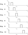
- Fig. 5 - Fig. 10 show the individual frequency shifted partial MIMO signals individually. Especially, here the signals 22 1 , 22 2 , 22 3 , 22 4 , 22 5 and 22 6 of Fig. 1 are shown. The individual signals 22 no longer comprise the frequency shifted partial MIMO signals of the other measuring paths 12, since they have been filtered by the first filters 13.
- a resulting partial MIMO signal 24 as indicated in Fig. 1 is shown. It has the correct carrier frequency and bandwidth. All different partial MIMO signals 24 1 - 24 6 seem identical in the frequency domain but might contain different data content.
- a plurality of frequency shifted partial MIMO signals is generated within a first signal generator output signal. These signals are frequency shifted, so that they do not overlap.
- a gap of ten or twenty percent of the bandwidth of a single partial MIMO signal might be employed between the frequency shifted partial MIMO signals in order to ensure that no overlap can occur.
- a second step 101 the first signal generator output signal is divided onto a plurality of signal paths.
- a third step 102 the frequency of each of the plurality of frequency shifted partial MIMO signals is shifted to a joint carrier frequency of the final MIMO signal. This results in a plurality of partial MIMO signals, forming the final MIMO signal.
- the embodiments of the present invention can be implemented by hardware, software, or any combination thereof.
- Various embodiments of the present invention may be implemented by one or more application specific integrated circuits (ASICs), digital signal processors (DSPs), digital signal processing devices (DSPDs), programmable logic devices (PLDs), field programmable gate arrays (FPGAs), processors, controllers, microcontrollers, microprocessors, or the like.
- ASICs application specific integrated circuits
- DSPs digital signal processors
- DSPDs digital signal processing devices
- PLDs programmable logic devices
- FPGAs field programmable gate arrays
- processors controllers, microcontrollers, microprocessors, or the like.
- Various embodiments of the present invention may also be implemented in the form of software modules, processes, functions, or the like which perform the features or operations described above.
- Software code can be stored in a memory unit so that it can be executed by a processor.
- the memory unit may be located inside or outside the processor and can communicate date with the processor through a variety of known means.
- the invention is not limited to the examples and especially not to a MIMO signal generator within a measuring device.
- the MIMO signal generator can also be employed in a base station or a mobile station or any other device generating memo signals.
- the characteristics of the exemplary embodiments can be used in any advantageous combination.
Landscapes
- Engineering & Computer Science (AREA)
- Computer Networks & Wireless Communication (AREA)
- Signal Processing (AREA)
- Physics & Mathematics (AREA)
- Electromagnetism (AREA)
- Radio Transmission System (AREA)
Abstract
Description
- The invention relates to a signal generator for generating MIMO signals, a measuring system comprising such a signal generator and a measuring method.
- During recent years, more and more MIMO devices are being used. A MIMO signal consists of a number of individual partial MIMO signals in the same frequency range with the same carrier frequency, emitted by different antennas in order to achieve spatial diversity.
- In order to generate a MIMO signal, conventionally a completely separate signal generator is used for each MIMO signal. Especially in a measuring setup, this requires a great deal of individual measurement devices. For example,
US 2017/0187477 A1 shows such a MIMO device. - Accordingly, one object of the invention among others is to provide a MIMO signal generator, measuring system and measuring method, which allow for generating a MIMO signal with a minimum number of components.
- According to a first aspect of the invention, a MIMO signal generator adapted to generate a MIMO signal, is provided. The MIMO signal generator comprises a signal generator, a signal divider and a frequency shifter. The signal generator is adapted to generate a plurality of frequency shifted partial MIMO signals within a first signal generator output signal, the frequency shifted partial MIMO signals being arranged on the frequency axis in a non-overlapping manner. The signal divider is adapted to divide the first signal generator output signal onto a plurality of signal paths.
- The frequency shifter preferably comprises a frequency shifting device in at least each but one of the plurality of signal paths. The frequency shifting devices are adapted to shift the frequencies of the plurality of frequency shifted partial MIMO signals to a joint carrier frequency, resulting in a plurality of partial MIMO signals, forming the MIMO signal. It is thereby possible to generate the MIMO signal using only a single signal generator.
- According to a preferred implementation form of the first aspect, the signal generator is adapted to arrange the plurality of frequency shifted partial MIMO signals on the frequency axis in a non-overlapping manner, by placing carrier frequencies of at least all but one the plurality of frequency shifted partial MIMO signals at different frequencies. A simple generating of the signal generator output signal is thereby assured.
- According to a further preferred implementation form of the first aspect, the different frequencies are spaced apart at least by a bandwidth of the MIMO signal. An overlap is thereby efficiently prevented.
- According to a further preferred implementation form of the first implementation form of the first aspect, the different frequencies are spaced apart at least by 110% of a bandwidth of the MIMO signal, preferably by 120% of the bandwidth of the MIMO signal. An overlap is thereby especially thoroughly prevented.
- According to a further preferred implementation form of the first aspect, each of the signal paths additionally comprises an antenna for transmitting the partial MIMO signal of the respective signal path over the air. This allows for performing over the air measurements on a device under test.
- According to a further preferred implementation form of the first aspect, at least one, preferably each, of the signal paths additionally comprises a first filter arranged between the signal divider and the frequency shifting device, adapted to remove signal components outside of a frequency shifted bandwidth of the signal path. This removes undesired signal components.
- According to a further preferred implementation form of the first aspect, at least one, preferably each, of the signal paths additionally comprises a second filter arranged between the frequency shifting device and an output of the signal path, adapted to remove signal components outside of the bandwidth of the MIMO signal. This allows for an especially simple filtering to remove undesired signal components.
- According to a further preferred implementation form of the first aspect, the frequency shifting devices are mixers. An especially simple and accurate frequency shifting is thereby possible.
- According to a further preferred implementation form of the first aspect, the mixers are connected to a common reference frequency. A mixing to an identical frequency is thereby achieved.
- According to a further preferred implementation form of the first aspect, the plurality of frequency shifted partial MIMO signals comprises N-frequency shifted partial MIMO signals. The signal divider is adapted to divide the first signal generator output signal onto N-signal paths. The MIMO signal generator comprises a further signal generator, adapted to generate M-frequency shifted partial MIMO signals within a second signal generator output signal, the M-frequency shifted partial MIMO signals being arranged on the frequency axis in a non-overlapping manner. The signal divider is then adapted to divide the second signal generator output signal onto M-signal paths. By this measure, it is possible to generate an even higher number of partial MIMO signals. This is especially relevant, when the first signal generator does not have the necessary bandwidth to place all desired partial MIMO signals side by side within the first signal generator output signal.
- According to a further preferred implementation form of the first aspect, the signal divider is arranged in a first housing, while the frequency shifter is arranged in a second housing. This gives great flexibility when generating the MIMO signal.
- According to a second aspect of the invention, an apparatus comprising a MIMO signal generator especially according to the first aspect is provided. The apparatus is a mobile station or a basestation or a measuring device. This allows for very flexibly using the MIMO signal generator.
- According to a third aspect of the invention, a measuring system comprising a MIMO signal generator especially according to the first aspect and a device under test is provided. The device under test comprises a MIMO signal receiver. The MIMO signal generator is adapted to provide the MIMO signal to the device under test. The device under test is adapted to receive the MIMO signal using the MIMO signal receiver. It is thereby possible to perform measurements on the device under test using MIMO signals.
- According to a preferred implementation form of the third aspect, the MIMO signal receiver is adapted to receive different data streams of a same frequency using separate antennas. A test of a spatial multiplexing device under test is thereby possible.
- According to a further preferred implementation form of the third aspect, the MIMO signal generator comprises an antenna for each signal path. The MIMO signal generator is adapted to transmit the MIMO signal to the device under test over the air using the antennas of the signal paths. A close to real-world measurement is thereby possible.
- According to a further preferred implementation form of the third aspect, the measuring system comprises an anechoic measuring chamber. The device under test and at least the antennas of the signal paths are arranged within the anechoic chamber. It is thereby assured that no stray emissions can influence the measurement.
- According to a fourth aspect of the invention, a method for generating a MIMO signal is provided. The method comprises generating a plurality of frequency shifted partial MIMO signals within a first signal generator output signal, the frequency shifted partial MIMO signals being arranged on the frequency axis in a non-overlapping manner, dividing the first signal generator output signal onto a plurality of signal paths, and shifting the frequencies of the plurality of frequency shifted partial MIMO signals to a joint carrier frequency, resulting in a plurality of partial MIMO signals, forming the MIMO signal.
- An exemplary embodiment of the invention is now further explained by way of example only with respect to the drawings, in which
- Fig. 1
- shows a first embodiment of the measuring system according to the third aspect of the invention, a first embodiment of the apparatus according to the second aspect of the invention, and a MIMO signal generator according to the first aspect of the invention;
- Fig. 2
- shows a second embodiment of the MIMO signal generator according to the first aspect of the invention;
- Fig. 3
- shows an exemplary partial MIMO signal;
- Fig. 4
- shows an exemplary signal generator output signal of the MIMO signal generator according to the first aspect of the invention;
- Fig. 5
- shows a frequency shifted partial MIMO signal in an exemplary MIMO signal generator of the first aspect of the invention;
- Fig. 6
- shows a frequency shifted partial MIMO signal in an exemplary MIMO signal generator of the first aspect of the invention;
- Fig. 7
- shows a frequency shifted partial MIMO signal in an exemplary MIMO signal generator of the first aspect of the invention;
- Fig. 8
- shows a frequency shifted partial MIMO signal in an exemplary MIMO signal generator of the first aspect of the invention;
- Fig. 9
- shows a frequency shifted partial MIMO signal in an exemplary MIMO signal generator of the first aspect of the invention;
- Fig. 10
- shows a frequency shifted partial MIMO signal in an exemplary MIMO signal generator of the first aspect of the invention;
- Fig. 11
- shows a resulting partial MIMO signal in an exemplary MIMO signal generator of the first aspect of the invention;
- Fig. 12
- shows an embodiment of the measuring method according to the fourth aspect of the invention.
- First we demonstrate the construction and function of an embodiment of the measuring system, apparatus and signal generator in
Fig. 1 . AlongFig. 2 , an alternative embodiment of the signal generator is described. With regard toFig. 3 - 11 , details of the function of different embodiments of the signal generator are described with regard to a number of signals. AlongFig. 12 , finally, the function of an embodiment of the measuring method is shown. Similar entities and reference numbers in different figures have been partially omitted. - Reference will now be made in detail to the preferred embodiments of the present invention, examples of which are illustrated in the accompanying drawings. However, the following embodiments of the present invention may be variously modified and the range of the present invention is not limited by the following embodiments.
- In
Fig. 1 , ameasuring system 1, comprising ameasuring device 2, comprising aMIMO signal generator 3 is shown. TheMIMO signal generator 3 is adapted to transmit aMIMO signal 25 to a device undertest 4. TheMIMO signal generator 3 comprises asignal generator 10 connected to asignal divider 11, which is connected to a number ofsignal paths signal paths 12. Each signal path comprises afirst filter first filter 13. Thefilter paths 12 moreover each comprise amixer mixer 14. Moreover, eachfilter path 12 comprises asecond filter filter 15, and anantenna antenna 16. - The
signal generator 10 generates a signalgenerator output signal 20, which is for example depicted inFig. 4 . The signalgenerator output signal 20 comprises a plurality of frequency shifted partial MIMO signals. These are arranged on the frequency axis in a non-overlapping manner. Each of the frequency shifted partial MIMO signals has an identical bandwidth, but does not need to comprise the same data content. This does not exclude the frequency shifted partial MIMO signals comprising the same data content, though. - The frequency shifted partial MIMO signals are spaced apart so that they do not overlap, by spacing the center frequencies of the frequency shifted partial MIMO signals apart by at least the bandwidth a single frequency shifted partial MIMO signal. In order to make the spacing even more secure, an additional spacing of 10% or 20% can be used.
- The signal
generator output signal 20 is handed to asignal divider 11, which divides the signalgenerator output signal 20 onto a plurality ofsignal paths 12. Eachsignal path 12 receives theidentical signal 21, which is in essence identical to the signalgenerator output signal 20. Within each of thefilter paths 12, first, a filtering by afirst filter 13 is performed. This filtering removes signal components outside of the bandwidth of the respective frequency shifted partial MIMO signal. As a next step, a mixing by therespective mixer 14 of thesignal path 12 is performed. The filtered frequency shiftedpartial MIMO signal 22 of therespective signal path 12 is mixed with a local oscillator frequency, which is specific to the respective mixer. The local oscillator signal of the respective mixer is chosen so that the filtered frequency shiftedpartial MIMO signal 22 of eachfilter path 12 is mixed to an identical carrier frequency of the resultingMIMO signal 25. This is achieved by frequency shifting the local oscillator signal of each mixer, accordingly. - Resulting mixed partial MIMO signals 23 of the
respective signal paths 12 are handed tosecond filters 15, which perform an additional filtering. In this filtering, signal components outside of the bandwidth of theMIMO signal 25 are removed. Here, each filter operates on the exact same frequency. - Finally, resulting filtered partial MIMO signals 24 are transmitted by the
antennas 16 to the device undertest 4. The signals during transmission are referred to asMIMO signal 25. - It is important to note that the
first filters 13, thesecond filters 15 and theantennas 16 are optional components. Instead of usingantennas 16, the partial MIMO signals 24 can also be provided to a device under test for example by cables. - Also it is important to note that the
MIMO signal generator 3 is not to be understood as restricted to the application in ameasuring device 2 or ameasuring system 1, as depicted here. Also, a mobile device or a basestation might generate a MIMO signal by use of aMIMO signal generator 3, as depicted here. - In
Fig. 2 , an alternative embodiment of theMIMO signal generator 3 is shown. Here, theMIMO signal generator 3 comprises afirst signal generator 101 connected to afirst signal divider 111, and asecond signal generator 102 connected to asecond signal divider 112. Thefirst signal generator 101 and thefirst signal divider 111 are identical to thesignal generator 10 and thesignal divider 11 ofFig. 1 . Also the further signal processing is identical, as shown there. The individual components of thesignal paths 12 have not been displayed for reasons of clarity, here. In fact, the set-up though is identical to the set-up ofFig. 1 . - Here, the
second signal generator 102 also generates a signalgenerator output signal 202, which is handed to thesecond signal divider 112 and divided onto thedifferent signal paths - This is especially relevant, when the bandwidth of the
signal generator 10 ofFig. 1 does not suffice to place all necessary partial MIMO signals side by side in the frequency domain within the signalgenerator output signal 20, due to the large bandwidth and number of partial MIMO signals. Also this approach is not limited to a second signal generator and signal divider. Also a larger number of individual signal generators and dividers can be used. InFig. 3 , a first exemplary partial MIMO signal is shown. It can clearly be seen here that the partial MIMO signal has a carrier frequency and a bandwidth. - In
Fig. 4 , a signalgenerator output signal 20, as shown inFig. 1 is depicted. Here, one of the partial MIMO signals is not frequency shifted, but remains in the correct frequency location. The remaining partial MIMO signals are frequency shifted with a gap of ten percent of the bandwidth of a partial MIMO signal. Therefore, all six partial MIMO signals are present in the signalgenerator output signal 20, but are frequency shifted. -
Fig. 5 - Fig. 10 show the individual frequency shifted partial MIMO signals individually. Especially, here thesignals Fig. 1 are shown. The individual signals 22 no longer comprise the frequency shifted partial MIMO signals of the other measuringpaths 12, since they have been filtered by the first filters 13. - Finally, in
Fig. 11 , a resultingpartial MIMO signal 24 as indicated inFig. 1 is shown. It has the correct carrier frequency and bandwidth. All different partial MIMO signals 241 - 246 seem identical in the frequency domain but might contain different data content. - Finally, in
Fig. 12 an embodiment of the measuring method according to the fourth aspect of the invention is shown. In a first step 100 a plurality of frequency shifted partial MIMO signals is generated within a first signal generator output signal. These signals are frequency shifted, so that they do not overlap. Advantageously, a gap of ten or twenty percent of the bandwidth of a single partial MIMO signal might be employed between the frequency shifted partial MIMO signals in order to ensure that no overlap can occur. - In a
second step 101 the first signal generator output signal is divided onto a plurality of signal paths. - In a
third step 102 the frequency of each of the plurality of frequency shifted partial MIMO signals is shifted to a joint carrier frequency of the final MIMO signal. This results in a plurality of partial MIMO signals, forming the final MIMO signal. - It is important to note, that the method embodiment and the device embodiments very closely relate to each other and that features described along
Fig. 1 - Fig. 11 can also be employed the method shown inFig. 12 . - The embodiments of the present invention can be implemented by hardware, software, or any combination thereof. Various embodiments of the present invention may be implemented by one or more application specific integrated circuits (ASICs), digital signal processors (DSPs), digital signal processing devices (DSPDs), programmable logic devices (PLDs), field programmable gate arrays (FPGAs), processors, controllers, microcontrollers, microprocessors, or the like.
- Various embodiments of the present invention may also be implemented in the form of software modules, processes, functions, or the like which perform the features or operations described above. Software code can be stored in a memory unit so that it can be executed by a processor. The memory unit may be located inside or outside the processor and can communicate date with the processor through a variety of known means.
The invention is not limited to the examples and especially not to a MIMO signal generator within a measuring device. The MIMO signal generator can also be employed in a base station or a mobile station or any other device generating memo signals. The characteristics of the exemplary embodiments can be used in any advantageous combination.
Claims (17)
- A MIMO signal generator, adapted to generate a MIMO signal, comprising a signal generator, a signal divider, and a frequency shifter,
wherein the signal generator is adapted to generate a plurality of frequency shifted partial MIMO signals within a first signal generator output signal, the frequency shifted partial MIMO signals being arranged on the frequency axis in a non-overlapping manner,
wherein the signal divider is adapted to divide the first signal generator output signal onto a plurality of signal paths. - The MIMO signal generator of claim 1,
wherein the frequency shifter comprises a frequency shifting device in at least one of the plurality of signals paths, and
wherein the frequency shifting devices are adapted to shift the frequencies of the plurality of frequency shifted partial MIMO signals to a joint carrier frequency, resulting in a plurality of partial MIMO signals, forming the MIMO signal. - The MIMO signal generator of claim 2,
wherein the signal generator is adapted arrange the plurality of frequency shifted partial MIMO signals on the frequency axis in a non-overlapping manner, by placing a carrier frequency of all but one of the plurality of frequency shifted partial MIMO signals to different frequencies. - The MIMO signal generator of claim 3,
wherein the different frequencies are spaced apart at least by a bandwidth of the MIMO signal, or
wherein the different frequencies are spaced apart at least by 110% of a bandwidth of the MIMO signal, preferably by 120% of the bandwidth of the MIMO signal. - The MIMO signal generator of claims 1 to 4,
wherein each of the signal paths additionally comprises an antenna for transmitting the partial MIMO signal over the air. - The MIMO signal generator of any of claims 1 - 5,
wherein at least one, preferably each, of the signal paths additionally comprises a first filter arranged between the signal divider and the frequency shifting device, adapted to remove signals outside of a frequency shifted bandwidth of the signal path. - The MIMO signal generator of claim 6,
wherein at least one, preferably each of the signal paths additionally comprises a second filter arranged between the frequency shifting device and an output of the signal path, adapted to remove signals outside of the bandwidth of the MIMO signal. - The MIMO signal generator of any of claims 1 to 7,
wherein the frequency shifting devices are mixers. - The MIMO signal generator of claim 8,
wherein the mixers are connected to common reference frequency means. - The MIMO signal generator of claim any of claims 1 to 9,
wherein the plurality of frequency shifted partial MIMO signals comprises N frequency shifted partial MIMO signals,
wherein the signal divider is adapted to divide the first signal generator output signal onto N signal paths, wherein the MIMO signal generator comprises a further signal generator, adapted to generate M frequency shifted partial MIMO signals within a second signal generator output signal, the M frequency shifted partial MIMO signals being arranged on the frequency axis in a non-overlapping manner,
wherein the signal divider is adapted to divide the second signal generator output signal in M signal paths. - The MIMO signal generator of any of claims 1 to 10,
wherein the signal divider is arranged in a first housing, and
wherein the frequency shifter is arranged in a second housing. - An apparatus comprising a MIMO signal generator according to any of claims 1 to 11,
wherein the apparatus is a mobile station or a basestation or measuring device. - A measuring system, comprising a MIMO signal generator according to any of claims 1 to 11, and a device under test,
wherein the device under test comprises a MIMO signal receiver,
wherein the MIMO signal generator is adapted to provide the MIMO signal to the device under test, and
wherein the device under test is adapted to receive the MIMO signal using the MIMO signal receiver. - The measuring system of claim 13,
wherein the MIMO signal receiver is adapted to receive different data streams of a same frequency using separate antennas. - The measuring system of claim 13 or 14,
wherein the MIMO signal generator comprises an antenna for each signal path, and
wherein the MIMO signal generator is adapted to transmit the MIMO signal to the device under test over the air using the antennas of the signal paths. - The measuring system of claim 14,
wherein the measuring system comprises an anechoic measuring chamber, and
wherein the device under test and at least the antennas of the signals paths are arranged within the anechoic chamber. - Method for generating a MIMO signal, comprising- generating a plurality of frequency shifted partial MIMO signals within a first signal generator output signal, the frequency shifted partial MIMO signals being arranged on the frequency axis in a non-overlapping manner,- dividing the first signal generator output signal onto a plurality of signal paths,- shifting the frequencies of the plurality of frequency shifted partial MIMO signals to a joint carrier frequency, resulting in a plurality of partial MIMO signals, forming the MIMO signal.
Applications Claiming Priority (1)
| Application Number | Priority Date | Filing Date | Title |
|---|---|---|---|
| US15/675,087 US10142038B1 (en) | 2017-08-11 | 2017-08-11 | MIMO signal generator with frequency multiplexing |
Publications (3)
| Publication Number | Publication Date |
|---|---|
| EP3442131A1 true EP3442131A1 (en) | 2019-02-13 |
| EP3442131B1 EP3442131B1 (en) | 2022-01-26 |
| EP3442131B8 EP3442131B8 (en) | 2022-02-23 |
Family
ID=59858573
Family Applications (1)
| Application Number | Title | Priority Date | Filing Date |
|---|---|---|---|
| EP17190539.1A Active EP3442131B8 (en) | 2017-08-11 | 2017-09-12 | Mimo signal generator with frequency multiplexing |
Country Status (3)
| Country | Link |
|---|---|
| US (1) | US10142038B1 (en) |
| EP (1) | EP3442131B8 (en) |
| CN (1) | CN109391302B (en) |
Cited By (1)
| Publication number | Priority date | Publication date | Assignee | Title |
|---|---|---|---|---|
| US11539388B2 (en) | 2020-02-26 | 2022-12-27 | Nokia Technologies Oy | Apparatus for receiving radio frequency signals and method of operating an apparatus |
Citations (3)
| Publication number | Priority date | Publication date | Assignee | Title |
|---|---|---|---|---|
| US20050047367A1 (en) * | 2001-12-06 | 2005-03-03 | Ismail Lakkis | Ultra-wideband communication systems and methods |
| EP1887685A2 (en) * | 2006-08-11 | 2008-02-13 | Tektronix International Sales GmbH | Apparatus and method of generating a plurality of synchronized radio frequency signals |
| US20170187477A1 (en) | 2010-11-17 | 2017-06-29 | Lg Electronics Inc. | Broadcast-signal transmitter/receiver and method for transmitting/receiving broadcast signals |
Family Cites Families (8)
| Publication number | Priority date | Publication date | Assignee | Title |
|---|---|---|---|---|
| US20080084951A1 (en) * | 2006-10-06 | 2008-04-10 | Helen Chen | Systems and methods for receiving multiple input, multiple output signals for test and analysis of multiple-input, multiple-output systems |
| EP2651057B1 (en) * | 2008-09-22 | 2020-07-22 | Sun Patent Trust | Clustered SC-FDMA radio communication device and method |
| JP5474949B2 (en) * | 2009-05-12 | 2014-04-16 | パナソニック株式会社 | Antenna evaluation apparatus and antenna evaluation method |
| US8576947B2 (en) | 2011-04-19 | 2013-11-05 | Litepoint Corporation | System and method for simultaneous MIMO signal testing with single vector signal analyzer |
| KR20150091370A (en) * | 2012-11-29 | 2015-08-10 | 인터디지탈 패튼 홀딩스, 인크 | Reduction of spectral leakage in an ofdm system |
| US20160050569A1 (en) * | 2014-08-18 | 2016-02-18 | Litepoint Corporation | Method for testing implicit beamforming performance of a multiple-input multiple-output radio frequency data packet signal transceiver |
| US9432133B2 (en) * | 2015-02-03 | 2016-08-30 | Keysight Technologies, Inc. | Vector signal generator channel characterization employing orthogonal modulation |
| CN107543978B (en) * | 2016-06-23 | 2021-08-24 | 是德科技股份有限公司 | System and method for calibrating radiation channel matrix in MIMO via OTA radiation test system |
-
2017
- 2017-08-11 US US15/675,087 patent/US10142038B1/en active Active
- 2017-09-12 EP EP17190539.1A patent/EP3442131B8/en active Active
- 2017-11-10 CN CN201711104321.6A patent/CN109391302B/en active Active
Patent Citations (3)
| Publication number | Priority date | Publication date | Assignee | Title |
|---|---|---|---|---|
| US20050047367A1 (en) * | 2001-12-06 | 2005-03-03 | Ismail Lakkis | Ultra-wideband communication systems and methods |
| EP1887685A2 (en) * | 2006-08-11 | 2008-02-13 | Tektronix International Sales GmbH | Apparatus and method of generating a plurality of synchronized radio frequency signals |
| US20170187477A1 (en) | 2010-11-17 | 2017-06-29 | Lg Electronics Inc. | Broadcast-signal transmitter/receiver and method for transmitting/receiving broadcast signals |
Cited By (1)
| Publication number | Priority date | Publication date | Assignee | Title |
|---|---|---|---|---|
| US11539388B2 (en) | 2020-02-26 | 2022-12-27 | Nokia Technologies Oy | Apparatus for receiving radio frequency signals and method of operating an apparatus |
Also Published As
| Publication number | Publication date |
|---|---|
| US10142038B1 (en) | 2018-11-27 |
| EP3442131B8 (en) | 2022-02-23 |
| CN109391302B (en) | 2023-02-17 |
| EP3442131B1 (en) | 2022-01-26 |
| CN109391302A (en) | 2019-02-26 |
Similar Documents
| Publication | Publication Date | Title |
|---|---|---|
| TWI711831B (en) | Front end module for automatic test equipment | |
| DE102012106101B4 (en) | Receiver circuits, circuitry and methods for testing one or more receive paths of a receiver circuit | |
| EP3198732A1 (en) | Frequency shifting a communications signal(s) in a multi-frequency distributed antenna system (das) to avoid or reduce frequency interference | |
| KR101882897B1 (en) | Reference signal distribution in multi-module systems | |
| US9392479B2 (en) | Pocket-size PIM inspector | |
| FI3432010T3 (en) | Distributed system for radio frequency environment simulation | |
| US20210067256A1 (en) | Transmit and receive radio frequency (rf) signals without the use of baseband generators and local oscillators for up conversion and down conversion | |
| US6526365B1 (en) | Low-power/wideband transfer function measurement method and apparatus | |
| CN114374408A (en) | Anti-interference test system | |
| US10142038B1 (en) | MIMO signal generator with frequency multiplexing | |
| TWI658742B (en) | System and method for concurrently testing multiple packet data signal transceivers capable of communicating via multiple radio access technologies | |
| CN103067105B (en) | Doppler frequency shift test device, the method for Doppler frequency shift device and communication module | |
| US20200150218A1 (en) | Apparatus and method for adjusting a suppression signal for suppressing an rf interference signal | |
| US11294068B2 (en) | RF signal system outputs calibration | |
| US20190312655A1 (en) | A method for determining a distance to a passive intermodulation source, an apparatus and a computer program product | |
| Sheremet et al. | Software-Defined Radio Wireless Communication Technology Design. MIMO 4× 4 Mode Configuration | |
| US20100007329A1 (en) | Device and method for the analysis of a measured signal transmitted via a multi-channel system | |
| JP4442390B2 (en) | Radio base station test apparatus and radio base station test method | |
| CN108075841A (en) | Test equipment and method on its beam forming performance testing equipment under test | |
| EP3007376A1 (en) | Multi-band testing method and apparatus | |
| EP2943004A1 (en) | Multi-band testing method and apparatus | |
| KR102246233B1 (en) | Method and system for transmitting and receiving multi-signals for generating radiating correction data | |
| KR102182281B1 (en) | Frequency synthesizer test apparatus for qualification model | |
| WO2019204536A1 (en) | Radio frequency transmitter with reduced number of internal interconnect signal paths for beamforming | |
| EP2838212A1 (en) | Multi-band multi-carrier testing method and apparatus |
Legal Events
| Date | Code | Title | Description |
|---|---|---|---|
| PUAI | Public reference made under article 153(3) epc to a published international application that has entered the european phase |
Free format text: ORIGINAL CODE: 0009012 |
|
| STAA | Information on the status of an ep patent application or granted ep patent |
Free format text: STATUS: THE APPLICATION HAS BEEN PUBLISHED |
|
| AK | Designated contracting states |
Kind code of ref document: A1 Designated state(s): AL AT BE BG CH CY CZ DE DK EE ES FI FR GB GR HR HU IE IS IT LI LT LU LV MC MK MT NL NO PL PT RO RS SE SI SK SM TR |
|
| AX | Request for extension of the european patent |
Extension state: BA ME |
|
| STAA | Information on the status of an ep patent application or granted ep patent |
Free format text: STATUS: REQUEST FOR EXAMINATION WAS MADE |
|
| 17P | Request for examination filed |
Effective date: 20190813 |
|
| RBV | Designated contracting states (corrected) |
Designated state(s): AL AT BE BG CH CY CZ DE DK EE ES FI FR GB GR HR HU IE IS IT LI LT LU LV MC MK MT NL NO PL PT RO RS SE SI SK SM TR |
|
| STAA | Information on the status of an ep patent application or granted ep patent |
Free format text: STATUS: EXAMINATION IS IN PROGRESS |
|
| 17Q | First examination report despatched |
Effective date: 20200415 |
|
| GRAP | Despatch of communication of intention to grant a patent |
Free format text: ORIGINAL CODE: EPIDOSNIGR1 |
|
| STAA | Information on the status of an ep patent application or granted ep patent |
Free format text: STATUS: GRANT OF PATENT IS INTENDED |
|
| GRAS | Grant fee paid |
Free format text: ORIGINAL CODE: EPIDOSNIGR3 |
|
| INTG | Intention to grant announced |
Effective date: 20211008 |
|
| GRAA | (expected) grant |
Free format text: ORIGINAL CODE: 0009210 |
|
| STAA | Information on the status of an ep patent application or granted ep patent |
Free format text: STATUS: THE PATENT HAS BEEN GRANTED |
|
| AK | Designated contracting states |
Kind code of ref document: B1 Designated state(s): AL AT BE BG CH CY CZ DE DK EE ES FI FR GB GR HR HU IE IS IT LI LT LU LV MC MK MT NL NO PL PT RO RS SE SI SK SM TR |
|
| REG | Reference to a national code |
Ref country code: GB Ref legal event code: FG4D |
|
| REG | Reference to a national code |
Ref country code: AT Ref legal event code: REF Ref document number: 1466081 Country of ref document: AT Kind code of ref document: T Effective date: 20220215 |
|
| RBV | Designated contracting states (corrected) |
Designated state(s): AL AT BE BG CY CZ DE DK EE ES FI FR GB GR HR HU IS IT LT LU LV MC MK MT NL NO PL PT RO RS SE SI SK SM TR |
|
| REG | Reference to a national code |
Ref country code: IE Ref legal event code: FG4D |
|
| REG | Reference to a national code |
Ref country code: DE Ref legal event code: R096 Ref document number: 602017052697 Country of ref document: DE |
|
| REG | Reference to a national code |
Ref country code: LT Ref legal event code: MG9D |
|
| REG | Reference to a national code |
Ref country code: NL Ref legal event code: MP Effective date: 20220126 |
|
| REG | Reference to a national code |
Ref country code: AT Ref legal event code: MK05 Ref document number: 1466081 Country of ref document: AT Kind code of ref document: T Effective date: 20220126 |
|
| PG25 | Lapsed in a contracting state [announced via postgrant information from national office to epo] |
Ref country code: NL Free format text: LAPSE BECAUSE OF FAILURE TO SUBMIT A TRANSLATION OF THE DESCRIPTION OR TO PAY THE FEE WITHIN THE PRESCRIBED TIME-LIMIT Effective date: 20220126 |
|
| PG25 | Lapsed in a contracting state [announced via postgrant information from national office to epo] |
Ref country code: SK Free format text: LAPSE BECAUSE OF FAILURE TO SUBMIT A TRANSLATION OF THE DESCRIPTION OR TO PAY THE FEE WITHIN THE PRESCRIBED TIME-LIMIT Effective date: 20220126 Ref country code: SE Free format text: LAPSE BECAUSE OF FAILURE TO SUBMIT A TRANSLATION OF THE DESCRIPTION OR TO PAY THE FEE WITHIN THE PRESCRIBED TIME-LIMIT Effective date: 20220126 Ref country code: RS Free format text: LAPSE BECAUSE OF FAILURE TO SUBMIT A TRANSLATION OF THE DESCRIPTION OR TO PAY THE FEE WITHIN THE PRESCRIBED TIME-LIMIT Effective date: 20220126 Ref country code: PT Free format text: LAPSE BECAUSE OF FAILURE TO SUBMIT A TRANSLATION OF THE DESCRIPTION OR TO PAY THE FEE WITHIN THE PRESCRIBED TIME-LIMIT Effective date: 20220526 Ref country code: NO Free format text: LAPSE BECAUSE OF FAILURE TO SUBMIT A TRANSLATION OF THE DESCRIPTION OR TO PAY THE FEE WITHIN THE PRESCRIBED TIME-LIMIT Effective date: 20220426 Ref country code: LT Free format text: LAPSE BECAUSE OF FAILURE TO SUBMIT A TRANSLATION OF THE DESCRIPTION OR TO PAY THE FEE WITHIN THE PRESCRIBED TIME-LIMIT Effective date: 20220126 Ref country code: HR Free format text: LAPSE BECAUSE OF FAILURE TO SUBMIT A TRANSLATION OF THE DESCRIPTION OR TO PAY THE FEE WITHIN THE PRESCRIBED TIME-LIMIT Effective date: 20220126 Ref country code: ES Free format text: LAPSE BECAUSE OF FAILURE TO SUBMIT A TRANSLATION OF THE DESCRIPTION OR TO PAY THE FEE WITHIN THE PRESCRIBED TIME-LIMIT Effective date: 20220126 Ref country code: BG Free format text: LAPSE BECAUSE OF FAILURE TO SUBMIT A TRANSLATION OF THE DESCRIPTION OR TO PAY THE FEE WITHIN THE PRESCRIBED TIME-LIMIT Effective date: 20220426 |
|
| PG25 | Lapsed in a contracting state [announced via postgrant information from national office to epo] |
Ref country code: PL Free format text: LAPSE BECAUSE OF FAILURE TO SUBMIT A TRANSLATION OF THE DESCRIPTION OR TO PAY THE FEE WITHIN THE PRESCRIBED TIME-LIMIT Effective date: 20220126 Ref country code: LV Free format text: LAPSE BECAUSE OF FAILURE TO SUBMIT A TRANSLATION OF THE DESCRIPTION OR TO PAY THE FEE WITHIN THE PRESCRIBED TIME-LIMIT Effective date: 20220126 Ref country code: GR Free format text: LAPSE BECAUSE OF FAILURE TO SUBMIT A TRANSLATION OF THE DESCRIPTION OR TO PAY THE FEE WITHIN THE PRESCRIBED TIME-LIMIT Effective date: 20220427 Ref country code: FI Free format text: LAPSE BECAUSE OF FAILURE TO SUBMIT A TRANSLATION OF THE DESCRIPTION OR TO PAY THE FEE WITHIN THE PRESCRIBED TIME-LIMIT Effective date: 20220126 Ref country code: AT Free format text: LAPSE BECAUSE OF FAILURE TO SUBMIT A TRANSLATION OF THE DESCRIPTION OR TO PAY THE FEE WITHIN THE PRESCRIBED TIME-LIMIT Effective date: 20220126 |
|
| PG25 | Lapsed in a contracting state [announced via postgrant information from national office to epo] |
Ref country code: IS Free format text: LAPSE BECAUSE OF FAILURE TO SUBMIT A TRANSLATION OF THE DESCRIPTION OR TO PAY THE FEE WITHIN THE PRESCRIBED TIME-LIMIT Effective date: 20220526 |
|
| REG | Reference to a national code |
Ref country code: DE Ref legal event code: R097 Ref document number: 602017052697 Country of ref document: DE |
|
| PG25 | Lapsed in a contracting state [announced via postgrant information from national office to epo] |
Ref country code: SM Free format text: LAPSE BECAUSE OF FAILURE TO SUBMIT A TRANSLATION OF THE DESCRIPTION OR TO PAY THE FEE WITHIN THE PRESCRIBED TIME-LIMIT Effective date: 20220126 Ref country code: RO Free format text: LAPSE BECAUSE OF FAILURE TO SUBMIT A TRANSLATION OF THE DESCRIPTION OR TO PAY THE FEE WITHIN THE PRESCRIBED TIME-LIMIT Effective date: 20220126 Ref country code: EE Free format text: LAPSE BECAUSE OF FAILURE TO SUBMIT A TRANSLATION OF THE DESCRIPTION OR TO PAY THE FEE WITHIN THE PRESCRIBED TIME-LIMIT Effective date: 20220126 Ref country code: DK Free format text: LAPSE BECAUSE OF FAILURE TO SUBMIT A TRANSLATION OF THE DESCRIPTION OR TO PAY THE FEE WITHIN THE PRESCRIBED TIME-LIMIT Effective date: 20220126 Ref country code: CZ Free format text: LAPSE BECAUSE OF FAILURE TO SUBMIT A TRANSLATION OF THE DESCRIPTION OR TO PAY THE FEE WITHIN THE PRESCRIBED TIME-LIMIT Effective date: 20220126 |
|
| PG25 | Lapsed in a contracting state [announced via postgrant information from national office to epo] |
Ref country code: AL Free format text: LAPSE BECAUSE OF FAILURE TO SUBMIT A TRANSLATION OF THE DESCRIPTION OR TO PAY THE FEE WITHIN THE PRESCRIBED TIME-LIMIT Effective date: 20220126 |
|
| PLBE | No opposition filed within time limit |
Free format text: ORIGINAL CODE: 0009261 |
|
| STAA | Information on the status of an ep patent application or granted ep patent |
Free format text: STATUS: NO OPPOSITION FILED WITHIN TIME LIMIT |
|
| 26N | No opposition filed |
Effective date: 20221027 |
|
| PG25 | Lapsed in a contracting state [announced via postgrant information from national office to epo] |
Ref country code: SI Free format text: LAPSE BECAUSE OF FAILURE TO SUBMIT A TRANSLATION OF THE DESCRIPTION OR TO PAY THE FEE WITHIN THE PRESCRIBED TIME-LIMIT Effective date: 20220126 |
|
| PG25 | Lapsed in a contracting state [announced via postgrant information from national office to epo] |
Ref country code: MC Free format text: LAPSE BECAUSE OF FAILURE TO SUBMIT A TRANSLATION OF THE DESCRIPTION OR TO PAY THE FEE WITHIN THE PRESCRIBED TIME-LIMIT Effective date: 20220126 |
|
| REG | Reference to a national code |
Ref country code: BE Ref legal event code: MM Effective date: 20220930 |
|
| PG25 | Lapsed in a contracting state [announced via postgrant information from national office to epo] |
Ref country code: LU Free format text: LAPSE BECAUSE OF NON-PAYMENT OF DUE FEES Effective date: 20220912 |
|
| P01 | Opt-out of the competence of the unified patent court (upc) registered |
Effective date: 20230525 |
|
| PG25 | Lapsed in a contracting state [announced via postgrant information from national office to epo] |
Ref country code: IT Free format text: LAPSE BECAUSE OF FAILURE TO SUBMIT A TRANSLATION OF THE DESCRIPTION OR TO PAY THE FEE WITHIN THE PRESCRIBED TIME-LIMIT Effective date: 20220126 |
|
| PG25 | Lapsed in a contracting state [announced via postgrant information from national office to epo] |
Ref country code: BE Free format text: LAPSE BECAUSE OF NON-PAYMENT OF DUE FEES Effective date: 20220930 |
|
| PG25 | Lapsed in a contracting state [announced via postgrant information from national office to epo] |
Ref country code: HU Free format text: LAPSE BECAUSE OF FAILURE TO SUBMIT A TRANSLATION OF THE DESCRIPTION OR TO PAY THE FEE WITHIN THE PRESCRIBED TIME-LIMIT; INVALID AB INITIO Effective date: 20170912 |
|
| PG25 | Lapsed in a contracting state [announced via postgrant information from national office to epo] |
Ref country code: CY Free format text: LAPSE BECAUSE OF FAILURE TO SUBMIT A TRANSLATION OF THE DESCRIPTION OR TO PAY THE FEE WITHIN THE PRESCRIBED TIME-LIMIT Effective date: 20220126 |
|
| PG25 | Lapsed in a contracting state [announced via postgrant information from national office to epo] |
Ref country code: MK Free format text: LAPSE BECAUSE OF FAILURE TO SUBMIT A TRANSLATION OF THE DESCRIPTION OR TO PAY THE FEE WITHIN THE PRESCRIBED TIME-LIMIT Effective date: 20220126 |
|
| PG25 | Lapsed in a contracting state [announced via postgrant information from national office to epo] |
Ref country code: TR Free format text: LAPSE BECAUSE OF FAILURE TO SUBMIT A TRANSLATION OF THE DESCRIPTION OR TO PAY THE FEE WITHIN THE PRESCRIBED TIME-LIMIT Effective date: 20220126 |
|
| PG25 | Lapsed in a contracting state [announced via postgrant information from national office to epo] |
Ref country code: MT Free format text: LAPSE BECAUSE OF FAILURE TO SUBMIT A TRANSLATION OF THE DESCRIPTION OR TO PAY THE FEE WITHIN THE PRESCRIBED TIME-LIMIT Effective date: 20220126 |
|
| PGFP | Annual fee paid to national office [announced via postgrant information from national office to epo] |
Ref country code: DE Payment date: 20250919 Year of fee payment: 9 |
|
| PGFP | Annual fee paid to national office [announced via postgrant information from national office to epo] |
Ref country code: GB Payment date: 20250923 Year of fee payment: 9 |
|
| PGFP | Annual fee paid to national office [announced via postgrant information from national office to epo] |
Ref country code: FR Payment date: 20250925 Year of fee payment: 9 |