EP3442112A1 - Electrical motor device - Google Patents
Electrical motor device Download PDFInfo
- Publication number
- EP3442112A1 EP3442112A1 EP17779060.7A EP17779060A EP3442112A1 EP 3442112 A1 EP3442112 A1 EP 3442112A1 EP 17779060 A EP17779060 A EP 17779060A EP 3442112 A1 EP3442112 A1 EP 3442112A1
- Authority
- EP
- European Patent Office
- Prior art keywords
- power supply
- motor
- switching elements
- voltage
- period
- Prior art date
- Legal status (The legal status is an assumption and is not a legal conclusion. Google has not performed a legal analysis and makes no representation as to the accuracy of the status listed.)
- Ceased
Links
Images


Classifications
-
- H—ELECTRICITY
- H02—GENERATION; CONVERSION OR DISTRIBUTION OF ELECTRIC POWER
- H02P—CONTROL OR REGULATION OF ELECTRIC MOTORS, ELECTRIC GENERATORS OR DYNAMO-ELECTRIC CONVERTERS; CONTROLLING TRANSFORMERS, REACTORS OR CHOKE COILS
- H02P27/00—Arrangements or methods for the control of AC motors characterised by the kind of supply voltage
- H02P27/04—Arrangements or methods for the control of AC motors characterised by the kind of supply voltage using variable-frequency supply voltage, e.g. inverter or converter supply voltage
- H02P27/06—Arrangements or methods for the control of AC motors characterised by the kind of supply voltage using variable-frequency supply voltage, e.g. inverter or converter supply voltage using DC to AC converters or inverters
- H02P27/08—Arrangements or methods for the control of AC motors characterised by the kind of supply voltage using variable-frequency supply voltage, e.g. inverter or converter supply voltage using DC to AC converters or inverters with pulse width modulation
- H02P27/12—Arrangements or methods for the control of AC motors characterised by the kind of supply voltage using variable-frequency supply voltage, e.g. inverter or converter supply voltage using DC to AC converters or inverters with pulse width modulation pulsing by guiding the flux vector, current vector or voltage vector on a circle or a closed curve, e.g. for direct torque control
-
- H—ELECTRICITY
- H02—GENERATION; CONVERSION OR DISTRIBUTION OF ELECTRIC POWER
- H02P—CONTROL OR REGULATION OF ELECTRIC MOTORS, ELECTRIC GENERATORS OR DYNAMO-ELECTRIC CONVERTERS; CONTROLLING TRANSFORMERS, REACTORS OR CHOKE COILS
- H02P27/00—Arrangements or methods for the control of AC motors characterised by the kind of supply voltage
- H02P27/04—Arrangements or methods for the control of AC motors characterised by the kind of supply voltage using variable-frequency supply voltage, e.g. inverter or converter supply voltage
- H02P27/06—Arrangements or methods for the control of AC motors characterised by the kind of supply voltage using variable-frequency supply voltage, e.g. inverter or converter supply voltage using DC to AC converters or inverters
- H02P27/08—Arrangements or methods for the control of AC motors characterised by the kind of supply voltage using variable-frequency supply voltage, e.g. inverter or converter supply voltage using DC to AC converters or inverters with pulse width modulation
-
- H—ELECTRICITY
- H02—GENERATION; CONVERSION OR DISTRIBUTION OF ELECTRIC POWER
- H02M—APPARATUS FOR CONVERSION BETWEEN AC AND AC, BETWEEN AC AND DC, OR BETWEEN DC AND DC, AND FOR USE WITH MAINS OR SIMILAR POWER SUPPLY SYSTEMS; CONVERSION OF DC OR AC INPUT POWER INTO SURGE OUTPUT POWER; CONTROL OR REGULATION THEREOF
- H02M3/00—Conversion of DC power input into DC power output
- H02M3/02—Conversion of DC power input into DC power output without intermediate conversion into AC
- H02M3/04—Conversion of DC power input into DC power output without intermediate conversion into AC by static converters
- H02M3/10—Conversion of DC power input into DC power output without intermediate conversion into AC by static converters using discharge tubes with control electrode or semiconductor devices with control electrode
- H02M3/145—Conversion of DC power input into DC power output without intermediate conversion into AC by static converters using discharge tubes with control electrode or semiconductor devices with control electrode using devices of a triode or transistor type requiring continuous application of a control signal
- H02M3/155—Conversion of DC power input into DC power output without intermediate conversion into AC by static converters using discharge tubes with control electrode or semiconductor devices with control electrode using devices of a triode or transistor type requiring continuous application of a control signal using semiconductor devices only
- H02M3/156—Conversion of DC power input into DC power output without intermediate conversion into AC by static converters using discharge tubes with control electrode or semiconductor devices with control electrode using devices of a triode or transistor type requiring continuous application of a control signal using semiconductor devices only with automatic control of output voltage or current, e.g. switching regulators
- H02M3/158—Conversion of DC power input into DC power output without intermediate conversion into AC by static converters using discharge tubes with control electrode or semiconductor devices with control electrode using devices of a triode or transistor type requiring continuous application of a control signal using semiconductor devices only with automatic control of output voltage or current, e.g. switching regulators including plural semiconductor devices as final control devices for a single load
- H02M3/1582—Buck-boost converters
-
- H—ELECTRICITY
- H02—GENERATION; CONVERSION OR DISTRIBUTION OF ELECTRIC POWER
- H02M—APPARATUS FOR CONVERSION BETWEEN AC AND AC, BETWEEN AC AND DC, OR BETWEEN DC AND DC, AND FOR USE WITH MAINS OR SIMILAR POWER SUPPLY SYSTEMS; CONVERSION OF DC OR AC INPUT POWER INTO SURGE OUTPUT POWER; CONTROL OR REGULATION THEREOF
- H02M7/00—Conversion of AC power input into DC power output; Conversion of DC power input into AC power output
- H02M7/42—Conversion of DC power input into AC power output without possibility of reversal
- H02M7/44—Conversion of DC power input into AC power output without possibility of reversal by static converters
- H02M7/48—Conversion of DC power input into AC power output without possibility of reversal by static converters using discharge tubes with control electrode or semiconductor devices with control electrode
-
- H—ELECTRICITY
- H02—GENERATION; CONVERSION OR DISTRIBUTION OF ELECTRIC POWER
- H02M—APPARATUS FOR CONVERSION BETWEEN AC AND AC, BETWEEN AC AND DC, OR BETWEEN DC AND DC, AND FOR USE WITH MAINS OR SIMILAR POWER SUPPLY SYSTEMS; CONVERSION OF DC OR AC INPUT POWER INTO SURGE OUTPUT POWER; CONTROL OR REGULATION THEREOF
- H02M7/00—Conversion of AC power input into DC power output; Conversion of DC power input into AC power output
- H02M7/42—Conversion of DC power input into AC power output without possibility of reversal
- H02M7/44—Conversion of DC power input into AC power output without possibility of reversal by static converters
- H02M7/48—Conversion of DC power input into AC power output without possibility of reversal by static converters using discharge tubes with control electrode or semiconductor devices with control electrode
- H02M7/53—Conversion of DC power input into AC power output without possibility of reversal by static converters using discharge tubes with control electrode or semiconductor devices with control electrode using devices of a triode or transistor type requiring continuous application of a control signal
- H02M7/537—Conversion of DC power input into AC power output without possibility of reversal by static converters using discharge tubes with control electrode or semiconductor devices with control electrode using devices of a triode or transistor type requiring continuous application of a control signal using semiconductor devices only, e.g. single switched pulse inverters
- H02M7/5387—Conversion of DC power input into AC power output without possibility of reversal by static converters using discharge tubes with control electrode or semiconductor devices with control electrode using devices of a triode or transistor type requiring continuous application of a control signal using semiconductor devices only, e.g. single switched pulse inverters in a bridge configuration
-
- H—ELECTRICITY
- H02—GENERATION; CONVERSION OR DISTRIBUTION OF ELECTRIC POWER
- H02M—APPARATUS FOR CONVERSION BETWEEN AC AND AC, BETWEEN AC AND DC, OR BETWEEN DC AND DC, AND FOR USE WITH MAINS OR SIMILAR POWER SUPPLY SYSTEMS; CONVERSION OF DC OR AC INPUT POWER INTO SURGE OUTPUT POWER; CONTROL OR REGULATION THEREOF
- H02M7/00—Conversion of AC power input into DC power output; Conversion of DC power input into AC power output
- H02M7/42—Conversion of DC power input into AC power output without possibility of reversal
- H02M7/44—Conversion of DC power input into AC power output without possibility of reversal by static converters
- H02M7/48—Conversion of DC power input into AC power output without possibility of reversal by static converters using discharge tubes with control electrode or semiconductor devices with control electrode
- H02M7/53—Conversion of DC power input into AC power output without possibility of reversal by static converters using discharge tubes with control electrode or semiconductor devices with control electrode using devices of a triode or transistor type requiring continuous application of a control signal
- H02M7/537—Conversion of DC power input into AC power output without possibility of reversal by static converters using discharge tubes with control electrode or semiconductor devices with control electrode using devices of a triode or transistor type requiring continuous application of a control signal using semiconductor devices only, e.g. single switched pulse inverters
- H02M7/5387—Conversion of DC power input into AC power output without possibility of reversal by static converters using discharge tubes with control electrode or semiconductor devices with control electrode using devices of a triode or transistor type requiring continuous application of a control signal using semiconductor devices only, e.g. single switched pulse inverters in a bridge configuration
- H02M7/53871—Conversion of DC power input into AC power output without possibility of reversal by static converters using discharge tubes with control electrode or semiconductor devices with control electrode using devices of a triode or transistor type requiring continuous application of a control signal using semiconductor devices only, e.g. single switched pulse inverters in a bridge configuration with automatic control of output voltage or current
- H02M7/53875—Conversion of DC power input into AC power output without possibility of reversal by static converters using discharge tubes with control electrode or semiconductor devices with control electrode using devices of a triode or transistor type requiring continuous application of a control signal using semiconductor devices only, e.g. single switched pulse inverters in a bridge configuration with automatic control of output voltage or current with analogue control of three-phase output
- H02M7/53876—Conversion of DC power input into AC power output without possibility of reversal by static converters using discharge tubes with control electrode or semiconductor devices with control electrode using devices of a triode or transistor type requiring continuous application of a control signal using semiconductor devices only, e.g. single switched pulse inverters in a bridge configuration with automatic control of output voltage or current with analogue control of three-phase output based on synthesising a desired voltage vector via the selection of appropriate fundamental voltage vectors, and corresponding dwelling times
-
- H—ELECTRICITY
- H02—GENERATION; CONVERSION OR DISTRIBUTION OF ELECTRIC POWER
- H02M—APPARATUS FOR CONVERSION BETWEEN AC AND AC, BETWEEN AC AND DC, OR BETWEEN DC AND DC, AND FOR USE WITH MAINS OR SIMILAR POWER SUPPLY SYSTEMS; CONVERSION OF DC OR AC INPUT POWER INTO SURGE OUTPUT POWER; CONTROL OR REGULATION THEREOF
- H02M7/00—Conversion of AC power input into DC power output; Conversion of DC power input into AC power output
- H02M7/42—Conversion of DC power input into AC power output without possibility of reversal
- H02M7/44—Conversion of DC power input into AC power output without possibility of reversal by static converters
- H02M7/48—Conversion of DC power input into AC power output without possibility of reversal by static converters using discharge tubes with control electrode or semiconductor devices with control electrode
- H02M7/53—Conversion of DC power input into AC power output without possibility of reversal by static converters using discharge tubes with control electrode or semiconductor devices with control electrode using devices of a triode or transistor type requiring continuous application of a control signal
- H02M7/537—Conversion of DC power input into AC power output without possibility of reversal by static converters using discharge tubes with control electrode or semiconductor devices with control electrode using devices of a triode or transistor type requiring continuous application of a control signal using semiconductor devices only, e.g. single switched pulse inverters
- H02M7/539—Conversion of DC power input into AC power output without possibility of reversal by static converters using discharge tubes with control electrode or semiconductor devices with control electrode using devices of a triode or transistor type requiring continuous application of a control signal using semiconductor devices only, e.g. single switched pulse inverters with automatic control of output wave form or frequency
- H02M7/5395—Conversion of DC power input into AC power output without possibility of reversal by static converters using discharge tubes with control electrode or semiconductor devices with control electrode using devices of a triode or transistor type requiring continuous application of a control signal using semiconductor devices only, e.g. single switched pulse inverters with automatic control of output wave form or frequency by pulse-width modulation
-
- H—ELECTRICITY
- H02—GENERATION; CONVERSION OR DISTRIBUTION OF ELECTRIC POWER
- H02P—CONTROL OR REGULATION OF ELECTRIC MOTORS, ELECTRIC GENERATORS OR DYNAMO-ELECTRIC CONVERTERS; CONTROLLING TRANSFORMERS, REACTORS OR CHOKE COILS
- H02P21/00—Arrangements or methods for the control of electric machines by vector control, e.g. by control of field orientation
- H02P21/22—Current control, e.g. using a current control loop
-
- H—ELECTRICITY
- H02—GENERATION; CONVERSION OR DISTRIBUTION OF ELECTRIC POWER
- H02P—CONTROL OR REGULATION OF ELECTRIC MOTORS, ELECTRIC GENERATORS OR DYNAMO-ELECTRIC CONVERTERS; CONTROLLING TRANSFORMERS, REACTORS OR CHOKE COILS
- H02P27/00—Arrangements or methods for the control of AC motors characterised by the kind of supply voltage
- H02P27/04—Arrangements or methods for the control of AC motors characterised by the kind of supply voltage using variable-frequency supply voltage, e.g. inverter or converter supply voltage
- H02P27/06—Arrangements or methods for the control of AC motors characterised by the kind of supply voltage using variable-frequency supply voltage, e.g. inverter or converter supply voltage using DC to AC converters or inverters
-
- G—PHYSICS
- G01—MEASURING; TESTING
- G01R—MEASURING ELECTRIC VARIABLES; MEASURING MAGNETIC VARIABLES
- G01R19/00—Arrangements for measuring currents or voltages or for indicating presence or sign thereof
- G01R19/165—Indicating that current or voltage is either above or below a predetermined value or within or outside a predetermined range of values
- G01R19/16533—Indicating that current or voltage is either above or below a predetermined value or within or outside a predetermined range of values characterised by the application
- G01R19/16538—Indicating that current or voltage is either above or below a predetermined value or within or outside a predetermined range of values characterised by the application in AC or DC supplies
- G01R19/16542—Indicating that current or voltage is either above or below a predetermined value or within or outside a predetermined range of values characterised by the application in AC or DC supplies for batteries
-
- H—ELECTRICITY
- H02—GENERATION; CONVERSION OR DISTRIBUTION OF ELECTRIC POWER
- H02M—APPARATUS FOR CONVERSION BETWEEN AC AND AC, BETWEEN AC AND DC, OR BETWEEN DC AND DC, AND FOR USE WITH MAINS OR SIMILAR POWER SUPPLY SYSTEMS; CONVERSION OF DC OR AC INPUT POWER INTO SURGE OUTPUT POWER; CONTROL OR REGULATION THEREOF
- H02M1/00—Details of apparatus for conversion
- H02M1/0064—Magnetic structures combining different functions, e.g. storage, filtering or transformation
-
- H—ELECTRICITY
- H02—GENERATION; CONVERSION OR DISTRIBUTION OF ELECTRIC POWER
- H02M—APPARATUS FOR CONVERSION BETWEEN AC AND AC, BETWEEN AC AND DC, OR BETWEEN DC AND DC, AND FOR USE WITH MAINS OR SIMILAR POWER SUPPLY SYSTEMS; CONVERSION OF DC OR AC INPUT POWER INTO SURGE OUTPUT POWER; CONTROL OR REGULATION THEREOF
- H02M7/00—Conversion of AC power input into DC power output; Conversion of DC power input into AC power output
- H02M7/42—Conversion of DC power input into AC power output without possibility of reversal
- H02M7/44—Conversion of DC power input into AC power output without possibility of reversal by static converters
- H02M7/48—Conversion of DC power input into AC power output without possibility of reversal by static converters using discharge tubes with control electrode or semiconductor devices with control electrode
- H02M7/53—Conversion of DC power input into AC power output without possibility of reversal by static converters using discharge tubes with control electrode or semiconductor devices with control electrode using devices of a triode or transistor type requiring continuous application of a control signal
- H02M7/537—Conversion of DC power input into AC power output without possibility of reversal by static converters using discharge tubes with control electrode or semiconductor devices with control electrode using devices of a triode or transistor type requiring continuous application of a control signal using semiconductor devices only, e.g. single switched pulse inverters
- H02M7/5387—Conversion of DC power input into AC power output without possibility of reversal by static converters using discharge tubes with control electrode or semiconductor devices with control electrode using devices of a triode or transistor type requiring continuous application of a control signal using semiconductor devices only, e.g. single switched pulse inverters in a bridge configuration
- H02M7/53871—Conversion of DC power input into AC power output without possibility of reversal by static converters using discharge tubes with control electrode or semiconductor devices with control electrode using devices of a triode or transistor type requiring continuous application of a control signal using semiconductor devices only, e.g. single switched pulse inverters in a bridge configuration with automatic control of output voltage or current
- H02M7/53873—Conversion of DC power input into AC power output without possibility of reversal by static converters using discharge tubes with control electrode or semiconductor devices with control electrode using devices of a triode or transistor type requiring continuous application of a control signal using semiconductor devices only, e.g. single switched pulse inverters in a bridge configuration with automatic control of output voltage or current with digital control
-
- H—ELECTRICITY
- H02—GENERATION; CONVERSION OR DISTRIBUTION OF ELECTRIC POWER
- H02P—CONTROL OR REGULATION OF ELECTRIC MOTORS, ELECTRIC GENERATORS OR DYNAMO-ELECTRIC CONVERTERS; CONTROLLING TRANSFORMERS, REACTORS OR CHOKE COILS
- H02P2209/00—Indexing scheme relating to controlling arrangements characterised by the waveform of the supplied voltage or current
- H02P2209/01—Motors with neutral point connected to the power supply
-
- H—ELECTRICITY
- H02—GENERATION; CONVERSION OR DISTRIBUTION OF ELECTRIC POWER
- H02P—CONTROL OR REGULATION OF ELECTRIC MOTORS, ELECTRIC GENERATORS OR DYNAMO-ELECTRIC CONVERTERS; CONTROLLING TRANSFORMERS, REACTORS OR CHOKE COILS
- H02P2209/00—Indexing scheme relating to controlling arrangements characterised by the waveform of the supplied voltage or current
- H02P2209/13—Different type of waveforms depending on the mode of operation
Definitions
- the present invention relates to a motor apparatus.
- Patent document 1 discloses a motor apparatus that includes a battery connected to a neutral point of stator coils and performs step-up control. The motor apparatus opens the switch located between the battery and the neutral point when there is an abnormality.
- Patent Document 1 Japanese Laid-Open Patent Publication No. 2009-118633
- One object of the present invention is to provide a motor apparatus that easily allows for motor driving to be performed together with transformation driving, which is performed between two batteries, and only motor driving to be performed.
- a motor apparatus that achieves the above object includes a motor, an inverter circuit, a first power supply, a second power supply, and a control unit.
- the motor is configured to be driven by multiphase alternating current power.
- the inverter circuit includes a positive bus bar and a negative bus bar and is configured to supply multiphase alternating current power to the motor. Further, the inverter circuit includes upper arm switching elements that are respectively connected in series to lower arm switching elements to configure a plurality of switching element pairs.
- the first power supply is connected to the positive bus bar and the negative bus bar.
- the second power supply is connected to the negative bus bar and a neutral point of the motor.
- the control unit is configured to have the motor output a target torque and control the switching element pairs of the inverter circuit in each control cycle to transform a voltage of the second power supply in order to charge the first power supply or to transform a voltage of the first power supply in order to charge the second power supply. Further, the control unit is configured to adjust a ratio of a first period during which the upper arm switching elements are all turned on and lower arm switching elements are all turned off and a second period during which upper arm switching elements are all turned off and lower arm switching elements are all turned on to adjust a transformation ratio of the second power supply to the first power supply or a transformation ratio of the first power supply to the second power supply, and select one of a plurality of drive modes in each control cycle.
- the drive modes include a dual drive mode, which includes the first period and the second period in the same control cycle when the motor is being driven to perform motor driving and transformation driving, and a motor drive mode, which does not include the first period and the second period in the same control cycle when the motor is being driven to perform only motor driving.
- a motor apparatus 10 shown in Fig. 1 is mounted on a vehicle.
- the motor apparatus 10 includes an inverter circuit 20, a motor 30, a first power supply 40, a second power supply 50, a control unit 70, and voltage sensors 80 and 81.
- the first power supply 40 is a direct current power supply, for example, a 48-volt on-board battery.
- the first power supply 40 is connected to a positive bus bar Lp and a negative bus bar Ln of the inverter circuit 20. More specifically, a positive electrode of the first power supply 40 is connected to the positive bus bar Lp and a negative electrode of the first power supply 40 is connected to the negative bus bar Ln.
- the motor 30 is a three-phase motor that is rotated by three-phase alternating current power, which is multiphase alternating current power.
- the motor 30 includes three stator coils 31, 32, and 33 that are in a star connection.
- the motor 30 includes a neutral point A.
- the inverter circuit 20 is configured to supply the motor 30 with three phase alternating current, which is a multiphase alternating current.
- the inverter circuit 20 includes switching elements S1 and S2, which configure U-phase upper and lower arms, switching elements S3 and S4, which configure V-phase upper and lower arms, and switching elements S5 and S6, which configure W-phase upper and lower arms.
- IGBTs are used as the switching elements S1 to S6.
- Diodes (D1 to D6) are connected in anti-parallel to the switching elements S1 to S6. Between the positive bus bar Lp and the negative bus bar Ln, the switching elements S1 and S2 are connected in series, the switching elements S3 and S4 are connected in series and the switching elements S5 and S6 are connected in series.
- the coil 31 of the three-phase motor 30 includes an end that is connected to a location between the switching elements S1 and S2.
- the coil 32 of the three-phase motor 30 includes an end that is connected to a location between the switching elements S3 and S4.
- the coil 33 of the three-phase motor 30 includes an end that is connected to a location between the switching elements S5 and S6.
- the inverter circuit 20 includes the upper arm switching elements S1, S3, and S5, respectively connected in series to the lower arm switching elements S2, S4, and S6 to configure a plurality of (specifically, three) switching element pairs. Further, the positive bus bar Lp and the negative bus bar Ln are connected by a capacitor 60 that is located closer to the first power supply 40 than the switching elements S1 to S6.
- the second power supply 50 is a direct current power supply, for example, a 12-volt on-board battery.
- the first power supply 40 is a high voltage battery having a higher voltage compared to the second power supply 50.
- the second power supply 50 is connected to the negative bus bar Ln of the inverter circuit 20 and the neutral point A of the motor 30. More specifically, a positive electrode of the second power supply 50 is connected to the neutral point A of the motor 30, and a negative electrode of the second power supply 50 is connected to the negative bus bar Ln.
- the control unit 70 includes a drive circuit 71 and a controller 72.
- the drive circuit 71 is connected to a gate terminal of each of the switching elements S1 to S6.
- the controller 72 may be, for example, a control circuit, specifically, one or more exclusive hardware circuits such as ASICs, one or more processors that run on a computer program (software), or a combination of the above.
- a processor includes a CPU and a memory such as a RAM and a ROM.
- the memory stores program codes or commands that are configured to have the CPU execute processes.
- the memory which is a computer readable medium, may be any available medium that is accessible by a versatile or a dedicated computer.
- the controller 72 turns each of the switching elements S1 to S6 on and off with the drive circuit 71.
- the switching elements S1, S2, S3, S4, S5, and S6 undergo switching operations to transform the direct current generated by the first power supply 40 to alternating current that is supplied to the three-phase motor 30, which is a multiphase motor and in which the coils 31, 32, and 33 are in a star connection. That is, an inverter (inverter circuit 20, control unit 70, or the like) performs space vector PWM control.
- the controller 72 is configured to input torque instruction signals and rotation speed instruction signals in order to obtain a torque instruction value (or torque estimation value) and a rotation speed instruction value (or rotation speed estimation value). Further, the controller 72 is connected to voltage sensors 80 and 81.
- the voltage sensor 80 detects the inter-terminal voltage of the first power supply 40.
- the voltage sensor 81 detects the inter-terminal voltage of the second power supply 50.
- the controller 72 receives signals from the voltage sensors 80 and 81 to obtain the inter-terminal voltages of the first power supply 40 and the inter-terminal voltage of the second power supply 50. Further, the controller 72 uses the inter-terminal voltage of the first power supply 40 to obtain the state of charge (charging rate) of the first power supply 40, and the controller 72 uses the inter-terminal voltage of the second power supply 50 to obtain the state of charge (charging rate) of the second power supply 50. Additionally, the controller 72 obtains an open voltage (inter-terminal voltage of second power supply 50 with no load: open circuit voltage) of the second power supply 50 from the inter-terminal voltage of the second power supply 50. In this manner, the controller 72 determines whether or not the second power supply 50 is fully charged.
- the control unit 70 is configured to set a dual drive mode, which is shown in Figs. 2A and 2B and Figs. 3A and 3B , a motor drive mode, which is shown in Figs. 4A and 4B , and a transformation drive mode (step-up and step-down drive mode), which is shown in Figs. 5A and 5B .
- the control unit 70 has the motor 30 output a target torque and controls the switching element pairs (S1 and S2, S3 and S4, and S5 and S6) of the inverter circuit 20 in each control cycle either by stepping up (transforming) the voltage of the second power supply 50 to charge the first power supply 40 or by stepping down (transforming) the voltage of the first power supply 40 to charge the second power supply 50.
- control unit 70 is configured to adjust a ratio between a first period during which the upper arm switching elements S1, S3, and S5 are all turned on and the lower arm switching elements S2, S4, and S6 are all turned off and a second period during which the upper arm switching elements S1, S3, and S5 are all turned off and the lower arm switching elements S2, S4, and S6 are all turned on to adjust a step-up ratio (transformation ratio) of the second power supply 50 to the first power supply 40 or a step-down ratio (transformation ratio) of the first power supply 40 to the second power supply 50.
- the control unit 70 includes the first period and the second period in the same control cycle when the motor 30 is being driven to perform motor driving and transformation driving (step-up and step-down driving).
- the controller 72 monitors the state of charge of the first power supply 40 and the state of charge of the second power supply 50. In accordance with the state of charge, the controller 72 charges one of the power supplies with the other one of the power supplies. In other words, when the charging rate of the first power supply 40 is low, the controller 72 steps up the voltage of the second power supply 50 to charge the first power supply 40. Further, when the charging rate of the second power supply 50 is low, the controller 72 steps down the voltage of the first power supply 40 to charge the second power supply 50.
- control unit 70 does not include the first period and the second period in the same control cycle when the motor 30 is being driven so as to perform only motor driving.
- the control unit 70 in the transformation drive mode (step-up and step-down drive mode), includes the first period and the second period in the same control cycle and does not drive the motor 30.
- the control unit 70 is configured to switch to the dual drive mode, the motor drive mode, or the transformation drive mode in each control cycle. That is, the control unit 70 is configured to select one of a plurality of the drive modes in each control cycle. Further, the control unit 70 executes a process illustrated in Fig. 6 to switch to the dual drive mode, the motor drive mode, or the transformation drive mode (step-up and step-down drive mode) in accordance with the situation of the second power supply 50 and the motor 30.
- the timing when the upper arm switching elements S1, S3, and S5 fall from on to off and the timing when the lower arm switching elements S2, S4, and S6 rise from off to on may be provided with a delay so as not to be synchronized.
- the timing when the upper arm switching elements S1, S3, and S5 rise from off to on and the timing when the lower arm switching elements S2, S4, and S6 fall from on to off may be provided with a delay so as not to be synchronize.
- the low voltage second power supply 50 is connected to the neutral point A of the motor 30. Further, the coils 31, 32, 33 of the motor 30 are used as a step-up and step-down inductor to obtain a transformer circuit (step-up and step-down circuit). This allows for the implementation of a control method (switching method) for performing voltage step-up and step-down when the motor is being driven.
- the positive electrode of the low voltage second power supply 50 is connected to the neutral point A of the motor 30.
- the low voltage second power supply 50 and the high voltage first power supply 40 share negative electrodes.
- the first period simultaneously turns on the upper arm switching elements S1, S3, and S5
- the second period simultaneously turns off the lower arm switching elements S2, S4, and S6.
- torque is not generated with the motor 30.
- the transformation ratio (step-up ratio, step-down ratio) is D/(D-1).
- D represents the duty ratio of the on time of a zero voltage vector V0 to the on time of a zero voltage vector V7. More specifically, as shown in Fig.
- the transformation ratio is equal to ⁇ T1/(T1+T2+T3) ⁇ / ⁇ T1/(T1+T2+T3)-1 ⁇ where T1 represents the on period of the zero voltage vector V7, T2 represents a former on period of the zero voltage vector V0, and T3 represents a latter on period of the zero voltage vector V0.
- the inverter adjusts the duty ratio of the upper switching elements S1, S3, and S5 and the lower switching elements S2, S4 and S6 to perform voltage step-up and step-down (transformation). More specifically, the inverter adjusts the ratio of the first period and the second period to adjust the step-up ratio of the second power supply 50 to the first power supply 40 or the step-down ratio of the first power supply 40 to the second power supply 50 so as to perform voltage step-up and step-down driving.
- the inverter circuit 20 does not require switches and inductors for voltage step-up and step-down, and the system is reduced in size and cost.
- the zero voltage vector V0 and the zero voltage vector V7 function to step up and step down the voltage. Further, the voltage vectors V4 and V5 are applied to the motor 30 as voltage for motor driving. In this case, the resultant vector B1, which is the total of the voltage vectors V4 and V5, is applied to the motor 30.
- the output voltage obtained from the switching shown in Fig. 2A is the same as the output voltage obtained from the switching shown in Fig. 3A .
- the step-up and step-down effect obtained from the switching shown in Fig. 2A is the same as the step-up and step-down effect obtained from the switching shown in Fig. 3A .
- Fig. 4A shows an example of the PWM control in the motor drive mode when only the motor 30 is being driven.
- the on period of the switching elements are adjusted to eliminate the period during which the zero voltage vector V0 is generated and the period during which the zero voltage vector V7 is generated so that voltage step-up and step-down is not performed (no current flows at neutral point A) and only driving of the motor 30 is allowed.
- the resultant vector B1 which is the total of the voltage vectors V4 and V5 shown in Fig. 2B
- the resultant vector B2 which is the total of the voltage vectors V4 and V5 shown in Fig. 4B
- the voltage resulting from the resultant vector B1 and applied to the motor 30 is the same as the voltage resulting from the resultant vector the B2 and applied to the motor 30.
- the transformation drive mode which only performs voltage step-up and step-down, only requires the zero voltage vector V0 and the zero voltage vector V7 to be used.
- the transformation drive mode allows voltage step-up and step-down to be performed without generating torque with the motor 30.
- the dual drive mode, the motor drive mode, and the transformation drive mode have different space vectors in each switching cycle and can be selectively used in accordance with the driving situation or the like.
- step S100 the controller 72 determines the state of the second power supply 50, that is, whether or not the second power supply 50 is operating normally (whether or not abnormality has occurred). Specifically, the controller 72 determines whether or not the inter-terminal voltage of the second power supply 50, which is obtained by the voltage sensor 81 during the application of voltage, is less than a predetermined threshold value. The controller 72 determines that the second power supply 50 is operating normally when the inter-terminal voltage of the second power supply 50 is greater than the predetermined threshold value. Further, the controller 72 determines that the second power supply 50 has an abnormality when the inter-terminal voltage of the second power supply 50 is less than the predetermined threshold value.
- step S101 the controller 72 determines the state of charge of the second power supply 50, that is, whether the second power supply 50 is being charged or is fully charged. Specifically, the controller 72 determines whether the open voltage of the second power supply 50 is greater than a predetermined full charge threshold value or less than the predetermined full charge threshold value. The controller 72 determines that the second power supply 50 is fully charged when the open voltage of the second power supply 50 is greater than the predetermined full charge threshold value. Further, the controller 72 determines that the second power supply 50 is being charged when the open voltage of the second power supply 50 is less than the predetermined full charge threshold value.
- step S102 the controller 72 determines whether the motor 30 is operating with regular efficiency or in a drive mode of which efficiency is in a low range. Specifically, the controller 72 obtains the torque instruction value and the rotation speed instruction value and determines whether the efficiency of the motor 30 is in a normal range or a low-efficiency range with a three dimensional map (map indicating relationship of torque instruction value, rotation speed instruction value, and efficiency).
- the controller 72 sets the dual drive mode in step S103. Further, when the second power supply 50 has an abnormality or the second power supply 50 is fully charged, the controller 72 sets the motor drive mode at step S104. Additionally, when the second power supply 50 is operating normally, the second power supply 50 is being charged, and the motor 30 is operating in a drive mode of which the efficiency is in a low range, the controller 72 sets the transformation drive mode (step-up and step-down drive mode), which requires no torque, in step S105.
- the controller 72 sets the motor drive mode, which requires no current to flow to the second power supply 50. Further, when the motor 30 is operating in the low efficiency range, there is no need for torque current to flow to the motor 30. This allows the controller 72 to set the transformation drive mode (step-up and step-down drive mode), which only performs voltage step-up and step-down (transformation).
- An abnormality is determined with the voltage sensor 81. Instead, the current flowing to the motor 30 may be detected to determine that the second power supply 50 has an abnormality when the current value is less than a threshold value.
- the control unit 70 selects one of the drive modes in accordance with the situation of the second power supply 50. Instead, the control unit 70 may also select one of the drive modes in accordance with the situation of the first power supply 40.
- the number of phases of the motor 30 may be a number other than three.
- the first power supply 40 and the second power supply 50 may have any power voltage within a range including 12V, 24V, or 48V as long as the negative electrode of the first power supply 40 and the negative electrode of the second power supply 50 are common.
- the second power supply 50 has a lower voltage than the first power supply 40. Instead, the second power supply 50 may have a higher voltage than the first power supply 40.
- the first power supply 40 and the second power supply 50 may be rechargeable batteries, capacitors, or the like.
- the switching elements S1 to S6 are not limited to IGBTs and may be, for example, power MOSFETs.
Landscapes
- Engineering & Computer Science (AREA)
- Power Engineering (AREA)
- Inverter Devices (AREA)
- Control Of Ac Motors In General (AREA)
- Electric Propulsion And Braking For Vehicles (AREA)
Abstract
Description
- The present invention relates to a motor apparatus.
- In a motor apparatus, when supplying a motor with alternating current transformed by an inverter from direct current generated by a direct current power supply, there is a technique that transforms the voltage of the direct current with a transformer circuit located in a stage preceding the inverter. The transformer circuit includes switches and inductors. Such a system requires switches and inductors that are highly costly and large in size.
Patent document 1 discloses a motor apparatus that includes a battery connected to a neutral point of stator coils and performs step-up control. The motor apparatus opens the switch located between the battery and the neutral point when there is an abnormality. - Patent Document 1: Japanese Laid-Open Patent Publication No.
2009-118633 - When the motor is being driven, there may be cases in which there is a need to perform voltage transformation and there may be cases in which there is a need to perform only motor driving. Further, in the technique disclosed in
patent document 1, there is a need to open the switch when there is an abnormality. - One object of the present invention is to provide a motor apparatus that easily allows for motor driving to be performed together with transformation driving, which is performed between two batteries, and only motor driving to be performed.
- A motor apparatus that achieves the above object includes a motor, an inverter circuit, a first power supply, a second power supply, and a control unit. The motor is configured to be driven by multiphase alternating current power. The inverter circuit includes a positive bus bar and a negative bus bar and is configured to supply multiphase alternating current power to the motor. Further, the inverter circuit includes upper arm switching elements that are respectively connected in series to lower arm switching elements to configure a plurality of switching element pairs. The first power supply is connected to the positive bus bar and the negative bus bar. The second power supply is connected to the negative bus bar and a neutral point of the motor. The control unit is configured to have the motor output a target torque and control the switching element pairs of the inverter circuit in each control cycle to transform a voltage of the second power supply in order to charge the first power supply or to transform a voltage of the first power supply in order to charge the second power supply. Further, the control unit is configured to adjust a ratio of a first period during which the upper arm switching elements are all turned on and lower arm switching elements are all turned off and a second period during which upper arm switching elements are all turned off and lower arm switching elements are all turned on to adjust a transformation ratio of the second power supply to the first power supply or a transformation ratio of the first power supply to the second power supply, and select one of a plurality of drive modes in each control cycle. The drive modes include a dual drive mode, which includes the first period and the second period in the same control cycle when the motor is being driven to perform motor driving and transformation driving, and a motor drive mode, which does not include the first period and the second period in the same control cycle when the motor is being driven to perform only motor driving.
-
-
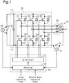
Fig. 1 is an electric diagram showing the configuration of a motor apparatus in accordance with one embodiment. -
Fig. 2A is a diagram showing a switching pattern (wave formation pattern) under space vector PWM control in a dual drive mode. -
Fig. 2B is a vector diagram of the dual drive mode. -
Fig. 3A is a diagram showing a switching pattern (wave formation pattern) of the space vector PWM control in the dual drive mode. -
Fig. 3B is a vector diagram of the dual drive mode. -
Fig. 4A is a diagram showing a switching pattern (wave formation pattern) of the space vector PWM control in a motor drive mode. -
Fig. 4B is a vector diagram of the motor drive mode. -
Fig. 5A is a diagram showing a switching pattern (wave formation pattern) of the space vector PWM control in a transformation drive mode. -
Fig. 5B is a vector diagram of the transformation drive mode. -
Fig. 6 is a flowchart illustrating the operation of the motor apparatus. - The present invention in accordance with one embodiment will now be described in detail with reference to the drawings.
- A
motor apparatus 10 shown inFig. 1 is mounted on a vehicle. Themotor apparatus 10 includes aninverter circuit 20, amotor 30, a first power supply 40, asecond power supply 50, acontrol unit 70, andvoltage sensors - The first power supply 40 is a direct current power supply, for example, a 48-volt on-board battery. The first power supply 40 is connected to a positive bus bar Lp and a negative bus bar Ln of the
inverter circuit 20. More specifically, a positive electrode of the first power supply 40 is connected to the positive bus bar Lp and a negative electrode of the first power supply 40 is connected to the negative bus bar Ln. - The
motor 30 is a three-phase motor that is rotated by three-phase alternating current power, which is multiphase alternating current power. Themotor 30 includes threestator coils motor 30 includes a neutral point A. - The
inverter circuit 20 is configured to supply themotor 30 with three phase alternating current, which is a multiphase alternating current. Theinverter circuit 20 includes switching elements S1 and S2, which configure U-phase upper and lower arms, switching elements S3 and S4, which configure V-phase upper and lower arms, and switching elements S5 and S6, which configure W-phase upper and lower arms. IGBTs are used as the switching elements S1 to S6. Diodes (D1 to D6) are connected in anti-parallel to the switching elements S1 to S6. Between the positive bus bar Lp and the negative bus bar Ln, the switching elements S1 and S2 are connected in series, the switching elements S3 and S4 are connected in series and the switching elements S5 and S6 are connected in series. Thecoil 31 of the three-phase motor 30 includes an end that is connected to a location between the switching elements S1 and S2. Thecoil 32 of the three-phase motor 30 includes an end that is connected to a location between the switching elements S3 and S4. Thecoil 33 of the three-phase motor 30 includes an end that is connected to a location between the switching elements S5 and S6. - Accordingly, the
inverter circuit 20 includes the upper arm switching elements S1, S3, and S5, respectively connected in series to the lower arm switching elements S2, S4, and S6 to configure a plurality of (specifically, three) switching element pairs. Further, the positive bus bar Lp and the negative bus bar Ln are connected by a capacitor 60 that is located closer to the first power supply 40 than the switching elements S1 to S6. - The
second power supply 50 is a direct current power supply, for example, a 12-volt on-board battery. Thus, the first power supply 40 is a high voltage battery having a higher voltage compared to thesecond power supply 50. Thesecond power supply 50 is connected to the negative bus bar Ln of theinverter circuit 20 and the neutral point A of themotor 30. More specifically, a positive electrode of thesecond power supply 50 is connected to the neutral point A of themotor 30, and a negative electrode of thesecond power supply 50 is connected to the negative bus bar Ln. - The
control unit 70 includes a drive circuit 71 and acontroller 72. The drive circuit 71 is connected to a gate terminal of each of the switching elements S1 to S6. Thecontroller 72 may be, for example, a control circuit, specifically, one or more exclusive hardware circuits such as ASICs, one or more processors that run on a computer program (software), or a combination of the above. A processor includes a CPU and a memory such as a RAM and a ROM. The memory stores program codes or commands that are configured to have the CPU execute processes. The memory, which is a computer readable medium, may be any available medium that is accessible by a versatile or a dedicated computer. Thecontroller 72 turns each of the switching elements S1 to S6 on and off with the drive circuit 71. More specifically, the switching elements S1, S2, S3, S4, S5, and S6 undergo switching operations to transform the direct current generated by the first power supply 40 to alternating current that is supplied to the three-phase motor 30, which is a multiphase motor and in which thecoils inverter circuit 20,control unit 70, or the like) performs space vector PWM control. Thecontroller 72 is configured to input torque instruction signals and rotation speed instruction signals in order to obtain a torque instruction value (or torque estimation value) and a rotation speed instruction value (or rotation speed estimation value). Further, thecontroller 72 is connected tovoltage sensors voltage sensor 80 detects the inter-terminal voltage of the first power supply 40. Thevoltage sensor 81 detects the inter-terminal voltage of thesecond power supply 50. Thecontroller 72 receives signals from thevoltage sensors second power supply 50. Further, thecontroller 72 uses the inter-terminal voltage of the first power supply 40 to obtain the state of charge (charging rate) of the first power supply 40, and thecontroller 72 uses the inter-terminal voltage of thesecond power supply 50 to obtain the state of charge (charging rate) of thesecond power supply 50. Additionally, thecontroller 72 obtains an open voltage (inter-terminal voltage ofsecond power supply 50 with no load: open circuit voltage) of thesecond power supply 50 from the inter-terminal voltage of thesecond power supply 50. In this manner, thecontroller 72 determines whether or not thesecond power supply 50 is fully charged. - The
control unit 70 is configured to set a dual drive mode, which is shown inFigs. 2A and 2B andFigs. 3A and 3B , a motor drive mode, which is shown inFigs. 4A and 4B , and a transformation drive mode (step-up and step-down drive mode), which is shown inFigs. 5A and 5B . - As shown in
Figs. 2A and 2B andFigs. 3A and 3B , in the dual drive mode, thecontrol unit 70 has themotor 30 output a target torque and controls the switching element pairs (S1 and S2, S3 and S4, and S5 and S6) of theinverter circuit 20 in each control cycle either by stepping up (transforming) the voltage of thesecond power supply 50 to charge the first power supply 40 or by stepping down (transforming) the voltage of the first power supply 40 to charge thesecond power supply 50. Further, thecontrol unit 70 is configured to adjust a ratio between a first period during which the upper arm switching elements S1, S3, and S5 are all turned on and the lower arm switching elements S2, S4, and S6 are all turned off and a second period during which the upper arm switching elements S1, S3, and S5 are all turned off and the lower arm switching elements S2, S4, and S6 are all turned on to adjust a step-up ratio (transformation ratio) of thesecond power supply 50 to the first power supply 40 or a step-down ratio (transformation ratio) of the first power supply 40 to thesecond power supply 50. In the dual drive mode, thecontrol unit 70 includes the first period and the second period in the same control cycle when themotor 30 is being driven to perform motor driving and transformation driving (step-up and step-down driving). More specifically, thecontroller 72 monitors the state of charge of the first power supply 40 and the state of charge of thesecond power supply 50. In accordance with the state of charge, thecontroller 72 charges one of the power supplies with the other one of the power supplies. In other words, when the charging rate of the first power supply 40 is low, thecontroller 72 steps up the voltage of thesecond power supply 50 to charge the first power supply 40. Further, when the charging rate of thesecond power supply 50 is low, thecontroller 72 steps down the voltage of the first power supply 40 to charge thesecond power supply 50. - As shown in
Figs. 4A and 4B , in the motor drive mode, thecontrol unit 70 does not include the first period and the second period in the same control cycle when themotor 30 is being driven so as to perform only motor driving. - As shown in
Figs. 5A and 5B , in the transformation drive mode (step-up and step-down drive mode), thecontrol unit 70 includes the first period and the second period in the same control cycle and does not drive themotor 30. - The
control unit 70 is configured to switch to the dual drive mode, the motor drive mode, or the transformation drive mode in each control cycle. That is, thecontrol unit 70 is configured to select one of a plurality of the drive modes in each control cycle. Further, thecontrol unit 70 executes a process illustrated inFig. 6 to switch to the dual drive mode, the motor drive mode, or the transformation drive mode (step-up and step-down drive mode) in accordance with the situation of thesecond power supply 50 and themotor 30. - In
Figs. 2A ,3A ,4A , and5A , the timing when the upper arm switching elements S1, S3, and S5 fall from on to off and the timing when the lower arm switching elements S2, S4, and S6 rise from off to on may be provided with a delay so as not to be synchronized. In the same manner, the timing when the upper arm switching elements S1, S3, and S5 rise from off to on and the timing when the lower arm switching elements S2, S4, and S6 fall from on to off may be provided with a delay so as not to be synchronize. - The dual drive mode, the motor drive mode, and the transformation drive mode will now be described in detail.
- The low voltage
second power supply 50 is connected to the neutral point A of themotor 30. Further, thecoils motor 30 are used as a step-up and step-down inductor to obtain a transformer circuit (step-up and step-down circuit). This allows for the implementation of a control method (switching method) for performing voltage step-up and step-down when the motor is being driven. - As shown in
Fig. 1 , the positive electrode of the low voltagesecond power supply 50 is connected to the neutral point A of themotor 30. The low voltagesecond power supply 50 and the high voltage first power supply 40 share negative electrodes. When actuating the inverter in a regular manner, the first period simultaneously turns on the upper arm switching elements S1, S3, and S5, and the second period simultaneously turns off the lower arm switching elements S2, S4, and S6. During the first period and the second period, torque is not generated with themotor 30. Further, the transformation ratio (step-up ratio, step-down ratio) is D/(D-1). Here, D represents the duty ratio of the on time of a zero voltage vector V0 to the on time of a zero voltage vector V7. More specifically, as shown inFig. 2A , the transformation ratio is equal to {T1/(T1+T2+T3)}/{T1/(T1+T2+T3)-1} where T1 represents the on period of the zero voltage vector V7, T2 represents a former on period of the zero voltage vector V0, and T3 represents a latter on period of the zero voltage vector V0. - The inverter adjusts the duty ratio of the upper switching elements S1, S3, and S5 and the lower switching elements S2, S4 and S6 to perform voltage step-up and step-down (transformation). More specifically, the inverter adjusts the ratio of the first period and the second period to adjust the step-up ratio of the
second power supply 50 to the first power supply 40 or the step-down ratio of the first power supply 40 to thesecond power supply 50 so as to perform voltage step-up and step-down driving. Thus, theinverter circuit 20 does not require switches and inductors for voltage step-up and step-down, and the system is reduced in size and cost. - Under the regular control (dual drive mode), as shown in
Figs. 2A and 2B , the zero voltage vector V0 and the zero voltage vector V7 function to step up and step down the voltage. Further, the voltage vectors V4 and V5 are applied to themotor 30 as voltage for motor driving. In this case, the resultant vector B1, which is the total of the voltage vectors V4 and V5, is applied to themotor 30. - As shown in
Figs. 2B and3B , the output voltage obtained from the switching shown inFig. 2A is the same as the output voltage obtained from the switching shown inFig. 3A . Further, the step-up and step-down effect obtained from the switching shown inFig. 2A is the same as the step-up and step-down effect obtained from the switching shown inFig. 3A . -
Fig. 4A shows an example of the PWM control in the motor drive mode when only themotor 30 is being driven. As shown in 4A, the on period of the switching elements are adjusted to eliminate the period during which the zero voltage vector V0 is generated and the period during which the zero voltage vector V7 is generated so that voltage step-up and step-down is not performed (no current flows at neutral point A) and only driving of themotor 30 is allowed. In this case, the resultant vector B1, which is the total of the voltage vectors V4 and V5 shown inFig. 2B , is the same as the resultant vector B2, which is the total of the voltage vectors V4 and V5 shown inFig. 4B . Further, the voltage resulting from the resultant vector B1 and applied to themotor 30 is the same as the voltage resulting from the resultant vector the B2 and applied to themotor 30. - This allows only the
motor 30 to be driven (no current flows at neutral point A). Further, this allows the transformation drive mode, which only performs voltage step-up and step-down (transformation), to be performed. Thus, the three modes can selectively be performed. - As shown in
Figs. 5A and 5B , the transformation drive mode, which only performs voltage step-up and step-down, only requires the zero voltage vector V0 and the zero voltage vector V7 to be used. The transformation drive mode allows voltage step-up and step-down to be performed without generating torque with themotor 30. - In this way, the dual drive mode, the motor drive mode, and the transformation drive mode have different space vectors in each switching cycle and can be selectively used in accordance with the driving situation or the like.
- The operation will now be described.
- As shown in
Fig. 6 , in step S100, thecontroller 72 determines the state of thesecond power supply 50, that is, whether or not thesecond power supply 50 is operating normally (whether or not abnormality has occurred). Specifically, thecontroller 72 determines whether or not the inter-terminal voltage of thesecond power supply 50, which is obtained by thevoltage sensor 81 during the application of voltage, is less than a predetermined threshold value. Thecontroller 72 determines that thesecond power supply 50 is operating normally when the inter-terminal voltage of thesecond power supply 50 is greater than the predetermined threshold value. Further, thecontroller 72 determines that thesecond power supply 50 has an abnormality when the inter-terminal voltage of thesecond power supply 50 is less than the predetermined threshold value. - As shown in
Fig. 6 , in step S101, thecontroller 72 determines the state of charge of thesecond power supply 50, that is, whether thesecond power supply 50 is being charged or is fully charged. Specifically, thecontroller 72 determines whether the open voltage of thesecond power supply 50 is greater than a predetermined full charge threshold value or less than the predetermined full charge threshold value. Thecontroller 72 determines that thesecond power supply 50 is fully charged when the open voltage of thesecond power supply 50 is greater than the predetermined full charge threshold value. Further, thecontroller 72 determines that thesecond power supply 50 is being charged when the open voltage of thesecond power supply 50 is less than the predetermined full charge threshold value. - As shown in
Fig. 6 , in step S102, thecontroller 72 determines whether themotor 30 is operating with regular efficiency or in a drive mode of which efficiency is in a low range. Specifically, thecontroller 72 obtains the torque instruction value and the rotation speed instruction value and determines whether the efficiency of themotor 30 is in a normal range or a low-efficiency range with a three dimensional map (map indicating relationship of torque instruction value, rotation speed instruction value, and efficiency). - As shown in
Fig. 6 , when thesecond power supply 50 is operating normally, thesecond power supply 50 is being charged, and themotor 30 is operating with normal efficiency, thecontroller 72 sets the dual drive mode in step S103. Further, when thesecond power supply 50 has an abnormality or thesecond power supply 50 is fully charged, thecontroller 72 sets the motor drive mode at step S104. Additionally, when thesecond power supply 50 is operating normally, thesecond power supply 50 is being charged, and themotor 30 is operating in a drive mode of which the efficiency is in a low range, thecontroller 72 sets the transformation drive mode (step-up and step-down drive mode), which requires no torque, in step S105. - In this way, when the
second power supply 50 has an abnormality or thesecond power supply 50 is in a fully charged state, thecontroller 72 sets the motor drive mode, which requires no current to flow to thesecond power supply 50. Further, when themotor 30 is operating in the low efficiency range, there is no need for torque current to flow to themotor 30. This allows thecontroller 72 to set the transformation drive mode (step-up and step-down drive mode), which only performs voltage step-up and step-down (transformation). - An abnormality is determined with the
voltage sensor 81. Instead, the current flowing to themotor 30 may be detected to determine that thesecond power supply 50 has an abnormality when the current value is less than a threshold value. - The above embodiment has the advantages described below.
- (1) The
motor apparatus 10 includes themotor 30 and theinverter circuit 20. Themotor 30 is driven by three-phase alternating current power that is multiphase alternating current power. Theinverter circuit 20 is configured to supply themotor 30 with three-phase alternating current power that is multiphase alternating current power. Theinverter circuit 20 includes the upper arm switching elements S1, S3, and S5 respectively connected in series to the lower arm switching elements S2, S4, and S6, to configure a plurality of (specifically, three) switching element pairs. Further, themotor apparatus 10 includes the first power supply 40, thesecond power supply 50, and thecontrol unit 70. The first power supply 40 is connected to the positive bus bar Lp and the negative bus bar Ln of theinverter circuit 20. Thesecond power supply 50 is connected to the negative bus bar Ln of theinverter circuit 20 and the neutral point A of themotor 30. Thecontrol unit 70 has themotor 30 output a target torque and controls the switching element pairs (S1 and S2, S3 and S4, and S5 and S6) of theinverter circuit 20 in each control cycle by stepping-up (transforming) the voltage of thesecond power supply 50 to charge the first power supply 40 and by stepping-down (transforming) the voltage of the first power supply 40 to charge thesecond power supply 50. Thecontrol unit 70 is configured to adjust the ratio of the first period during which the upper arm switching elements S1, S3, and S5 are all turned on and the lower arm switching elements S2, S4, and S6 are all turned off and the second period during which the upper arm switching elements S1, S3, and S5 are all turned off and the lower arm switching elements S2, S4, and S6 are all turned on to adjust the step-up ratio (transformation ratio) of thesecond power supply 50 to the first power supply 40 or the step-down ratio (transformation ratio) of the first power supply 40 to thesecond power supply 50. Further, thecontrol unit 70 is configured to select one of a plurality of drive modes in each control cycle. The drive modes include the dual drive mode, which includes the first period and the second period in the same control cycle when themotor 30 is being driven to perform motor driving and transformation driving (step-up and step-down driving), and the motor drive mode, which does not include the first period and the second period in the same control cycle when themotor 30 is being driven to perform only motor driving. In this way, in the dual drive mode, motor driving and transformation driving are performed. Further, in the motor drive mode, the switches do not have to be opened and only motor driving is performed. This allows themotor apparatus 10 to easily perform motor driving together with transformation driving (step-up and step-down driving), which is performed between the two batteries, or perform only motor driving. - (2) The drive modes further include the transformation drive mode (step-up and step-down drive mode) that does not drive the
motor 30 and includes the first period and the second period in the same control cycle. Thecontrol unit 70 is configured to select one of the drive modes in each control cycle in accordance with the situation of thesecond power supply 50 and themotor 30. Thus, themotor apparatus 10, in accordance with the situation of thesecond power supply 50 and themotor 30, easily performs motor driving and transformation driving, which is performed between the two batteries, only motor driving, or only transformation driving (step-up and step-down driving). - (3) The situation of the
second power supply 50 includes a situation of whether or not thesecond power supply 50 has an abnormality. This allows only motor driving to be performed when thesecond power supply 50 has an abnormality. - (4) The first power supply 40 is a high voltage battery having a higher voltage than the
second power supply 50 and is thus practical. - The embodiment described above is not limited to the foregoing description. For example, the present invention may be embodied in the following forms.
- The
control unit 70 selects one of the drive modes in accordance with the situation of thesecond power supply 50. Instead, thecontrol unit 70 may also select one of the drive modes in accordance with the situation of the first power supply 40. - The number of phases of the
motor 30 may be a number other than three. - The first power supply 40 and the
second power supply 50 may have any power voltage within a range including 12V, 24V, or 48V as long as the negative electrode of the first power supply 40 and the negative electrode of thesecond power supply 50 are common. - The
second power supply 50 has a lower voltage than the first power supply 40. Instead, thesecond power supply 50 may have a higher voltage than the first power supply 40. - The first power supply 40 and the
second power supply 50 may be rechargeable batteries, capacitors, or the like. - The switching elements S1 to S6 are not limited to IGBTs and may be, for example, power MOSFETs.
Claims (4)
- A motor apparatus comprising:a motor configured to be driven by multiphase alternating current power;an inverter circuit including a positive bus bar and a negative bus bar and configured to supply multiphase alternating current power to the motor, wherein the inverter circuit includes upper arm switching elements that are respectively connected in series to lower arm switching elements to configure a plurality of switching element pairs;a first power supply connected to the positive bus bar and the negative bus bar;a second power supply connected to the negative bus bar and a neutral point of the motor;a control unit configured to have the motor output a target torque and control the switching element pairs of the inverter circuit in each control cycle to transform a voltage of the second power supply in order to charge the first power supply or to transform a voltage of the first power supply in order to charge the second power supply, whereinthe control unit is configured to adjust a ratio of a first period during which the upper arm switching elements are all turned on and the lower arm switching elements are all turned off and a second period during which the upper arm switching elements are all turned off and the lower arm switching elements are all turned on to adjust a transformation ratio of the second power supply to the first power supply or a transformation ratio of the first power supply to the second power supply,the control unit is configured to select one of a plurality of drive modes in each control cycle, andthe drive modes include a dual drive mode, which includes the first period and the second period in the same control cycle when the motor is being driven to perform motor driving and transformation driving, and a motor drive mode, which does not include the first period and the second period in the same control cycle when the motor is being driven to perform only motor driving.
- The motor apparatus according to claim 1, wherein:the drive modes further includes a transformation drive mode, which does not drive the motor and includes the first period and the second period in the same control cycle; andthe control unit is configured to select one of the drive modes in each control cycle in accordance with a situation of the first power supply or the second power supply and a situation of the motor.
- The motor apparatus according to claim 2, wherein the situation of the first power supply or the second power supply includes a situation of whether or not the first power supply or the second power supply has an abnormality.
- The motor apparatus according to any one of claims 1 to 3, wherein the first power supply is a high voltage battery having a higher voltage than the second power supply.
Applications Claiming Priority (2)
| Application Number | Priority Date | Filing Date | Title |
|---|---|---|---|
| JP2016077294A JP6547672B2 (en) | 2016-04-07 | 2016-04-07 | Motor device |
| PCT/JP2017/013682 WO2017175681A1 (en) | 2016-04-07 | 2017-03-31 | Electrical motor device |
Publications (2)
| Publication Number | Publication Date |
|---|---|
| EP3442112A1 true EP3442112A1 (en) | 2019-02-13 |
| EP3442112A4 EP3442112A4 (en) | 2019-04-10 |
Family
ID=60000466
Family Applications (1)
| Application Number | Title | Priority Date | Filing Date |
|---|---|---|---|
| EP17779060.7A Ceased EP3442112A4 (en) | 2016-04-07 | 2017-03-31 | ELECTRIC MOTOR DEVICE |
Country Status (5)
| Country | Link |
|---|---|
| US (1) | US10574168B2 (en) |
| EP (1) | EP3442112A4 (en) |
| JP (1) | JP6547672B2 (en) |
| CN (1) | CN109121460B (en) |
| WO (1) | WO2017175681A1 (en) |
Families Citing this family (5)
| Publication number | Priority date | Publication date | Assignee | Title |
|---|---|---|---|---|
| CN109905051B (en) * | 2019-04-01 | 2020-12-01 | 北京交通大学 | Phase voltage equalization device and equalization method of three-phase inverter |
| CN110798117B (en) * | 2019-10-12 | 2021-08-31 | 华中科技大学 | A magnetic field modulation switched reluctance motor dual electrical port drive system and control method |
| CN112937337B (en) * | 2021-01-21 | 2025-05-13 | 华为数字能源技术有限公司 | Charging system and electric vehicle |
| JP7679790B2 (en) * | 2022-03-30 | 2025-05-20 | 株式会社豊田自動織機 | Power Conversion Systems |
| CN118611230B (en) * | 2024-08-06 | 2025-01-14 | 比亚迪股份有限公司 | Charging and discharging circuit, charging and discharging system and vehicle |
Family Cites Families (17)
| Publication number | Priority date | Publication date | Assignee | Title |
|---|---|---|---|---|
| JPH10113105A (en) * | 1996-10-09 | 1998-05-06 | Ryobi Ltd | Spool driving motor controller and spool driving motor control method for motor-driven fishing reel |
| US6518736B2 (en) * | 2000-06-26 | 2003-02-11 | Toyota Jidosha Kabushiki Kaisha | Mechanical power outputting apparatus and inverter apparatus |
| JP4346813B2 (en) * | 2000-11-15 | 2009-10-21 | トヨタ自動車株式会社 | Power output apparatus and control method thereof |
| JP2003102181A (en) * | 2001-09-25 | 2003-04-04 | Toyota Motor Corp | Power supply system and power supply method |
| JP3692993B2 (en) * | 2001-10-04 | 2005-09-07 | トヨタ自動車株式会社 | DRIVE DEVICE AND POWER OUTPUT DEVICE |
| JP2005204431A (en) * | 2004-01-16 | 2005-07-28 | Matsushita Electric Ind Co Ltd | Motor drive device |
| JP2005354825A (en) * | 2004-06-11 | 2005-12-22 | Nissan Motor Co Ltd | SOC calculation device for hybrid vehicle |
| JP5157372B2 (en) * | 2007-11-06 | 2013-03-06 | 株式会社デンソー | Multi-phase rotating electrical machine control device and multi-phase rotating electrical machine device |
| JP4441920B2 (en) | 2007-11-22 | 2010-03-31 | 株式会社デンソー | Power supply |
| JP5385058B2 (en) | 2009-09-04 | 2014-01-08 | 株式会社日本自動車部品総合研究所 | Vehicle motor control device |
| JP5505042B2 (en) * | 2010-03-31 | 2014-05-28 | 株式会社豊田自動織機 | Neutral point boost DC-three-phase converter |
| JP5567381B2 (en) * | 2010-04-27 | 2014-08-06 | 日立オートモティブシステムズ株式会社 | Power converter |
| JP5834768B2 (en) * | 2011-10-25 | 2015-12-24 | 株式会社デンソー | Generator motor control device |
| DE102013200674A1 (en) * | 2013-01-17 | 2014-07-17 | Bayerische Motoren Werke Aktiengesellschaft | Vehicle with an electric machine and two sub-nets |
| US9130482B2 (en) | 2013-02-20 | 2015-09-08 | Infineon Technologies Ag | Pseudo zero vectors for space vector modulation and enhanced space vector modulation |
| US9628003B2 (en) * | 2013-10-18 | 2017-04-18 | Mitsubishi Electric Corporation | Direct current power supply device, motor driving device, air conditioner, and refrigerator |
| US10315530B2 (en) * | 2015-04-16 | 2019-06-11 | Hyundai Motor Company | System and method for reducing speed ripple of drive motor of electric vehicle |
-
2016
- 2016-04-07 JP JP2016077294A patent/JP6547672B2/en not_active Expired - Fee Related
-
2017
- 2017-03-31 CN CN201780021029.XA patent/CN109121460B/en not_active Expired - Fee Related
- 2017-03-31 US US16/090,982 patent/US10574168B2/en not_active Expired - Fee Related
- 2017-03-31 EP EP17779060.7A patent/EP3442112A4/en not_active Ceased
- 2017-03-31 WO PCT/JP2017/013682 patent/WO2017175681A1/en not_active Ceased
Also Published As
| Publication number | Publication date |
|---|---|
| WO2017175681A1 (en) | 2017-10-12 |
| CN109121460A (en) | 2019-01-01 |
| CN109121460B (en) | 2020-07-07 |
| US10574168B2 (en) | 2020-02-25 |
| JP6547672B2 (en) | 2019-07-24 |
| US20190115863A1 (en) | 2019-04-18 |
| JP2017189053A (en) | 2017-10-12 |
| EP3442112A4 (en) | 2019-04-10 |
Similar Documents
| Publication | Publication Date | Title |
|---|---|---|
| US10574168B2 (en) | Electrical motor device | |
| US8624534B2 (en) | Control device for electric motor driving apparatus | |
| JP5954356B2 (en) | Electric vehicle | |
| CN107921879B (en) | Power regulation system and its control method | |
| CN103872970B (en) | For operating circuit arrangement and the method for motor | |
| JP4708483B2 (en) | Synchronous motor drive device | |
| JP5784553B2 (en) | Power converter | |
| US10978949B2 (en) | Method and apparatus for controlling a DC/DC power converter | |
| US9112442B2 (en) | Voltage conversion control device for motor | |
| EP3471264B1 (en) | Power output device | |
| JP2016059152A (en) | Control device of rotary electric machine | |
| JP4723743B2 (en) | Power output device | |
| CN113765350B (en) | Power supply unit | |
| CN110149048A (en) | Boost converter device and control method of boost converter device | |
| JP2020058131A (en) | Drive system | |
| JP2020054167A (en) | Power conversion apparatus | |
| JP4983938B2 (en) | Synchronous motor drive device | |
| CN112297902B (en) | Energy conversion devices, power systems and vehicles | |
| JP7816270B2 (en) | Power conversion device, program, and method for controlling power conversion device | |
| KR20150040232A (en) | Power conversion system for electric vehicle | |
| JP7021846B2 (en) | Control device | |
| JP2019047688A (en) | Motor drive device | |
| CN105322808B (en) | Inverter system, inverter apparatus and the method for controlling inverter system | |
| JP5293697B2 (en) | Power output device | |
| JP2025178854A (en) | Charging control device |
Legal Events
| Date | Code | Title | Description |
|---|---|---|---|
| STAA | Information on the status of an ep patent application or granted ep patent |
Free format text: STATUS: THE INTERNATIONAL PUBLICATION HAS BEEN MADE |
|
| PUAI | Public reference made under article 153(3) epc to a published international application that has entered the european phase |
Free format text: ORIGINAL CODE: 0009012 |
|
| STAA | Information on the status of an ep patent application or granted ep patent |
Free format text: STATUS: REQUEST FOR EXAMINATION WAS MADE |
|
| 17P | Request for examination filed |
Effective date: 20181012 |
|
| AK | Designated contracting states |
Kind code of ref document: A1 Designated state(s): AL AT BE BG CH CY CZ DE DK EE ES FI FR GB GR HR HU IE IS IT LI LT LU LV MC MK MT NL NO PL PT RO RS SE SI SK SM TR |
|
| AX | Request for extension of the european patent |
Extension state: BA ME |
|
| A4 | Supplementary search report drawn up and despatched |
Effective date: 20190308 |
|
| RIC1 | Information provided on ipc code assigned before grant |
Ipc: H02P 27/12 20060101ALI20190304BHEP Ipc: H02M 1/00 20060101ALI20190304BHEP Ipc: H02M 7/5387 20070101ALI20190304BHEP Ipc: H02M 7/5395 20060101ALI20190304BHEP Ipc: H02M 7/48 20070101ALI20190304BHEP Ipc: H02P 27/06 20060101AFI20190304BHEP Ipc: H02M 3/158 20060101ALI20190304BHEP |
|
| DAV | Request for validation of the european patent (deleted) | ||
| DAX | Request for extension of the european patent (deleted) | ||
| STAA | Information on the status of an ep patent application or granted ep patent |
Free format text: STATUS: EXAMINATION IS IN PROGRESS |
|
| 17Q | First examination report despatched |
Effective date: 20200304 |
|
| REG | Reference to a national code |
Ref country code: DE Ref legal event code: R003 |
|
| STAA | Information on the status of an ep patent application or granted ep patent |
Free format text: STATUS: THE APPLICATION HAS BEEN REFUSED |
|
| 18R | Application refused |
Effective date: 20220325 |