EP3442089A1 - Dual active bridge control circuit for use with unbalanced grid voltages - Google Patents
Dual active bridge control circuit for use with unbalanced grid voltages Download PDFInfo
- Publication number
- EP3442089A1 EP3442089A1 EP18186605.4A EP18186605A EP3442089A1 EP 3442089 A1 EP3442089 A1 EP 3442089A1 EP 18186605 A EP18186605 A EP 18186605A EP 3442089 A1 EP3442089 A1 EP 3442089A1
- Authority
- EP
- European Patent Office
- Prior art keywords
- phase
- voltage
- power
- active bridge
- dual active
- Prior art date
- Legal status (The legal status is an assumption and is not a legal conclusion. Google has not performed a legal analysis and makes no representation as to the accuracy of the status listed.)
- Granted
Links
Images




Classifications
-
- H—ELECTRICITY
- H02—GENERATION; CONVERSION OR DISTRIBUTION OF ELECTRIC POWER
- H02J—ELECTRIC POWER NETWORKS; CIRCUIT ARRANGEMENTS OR SYSTEMS FOR SUPPLYING OR DISTRIBUTING ELECTRIC POWER; SYSTEMS FOR STORING ELECTRIC ENERGY
- H02J7/00—Circuit arrangements for charging or discharging batteries or for supplying loads from batteries
- H02J7/02—Circuit arrangements for charging or discharging batteries or for supplying loads from batteries for charging batteries from AC mains by converters
-
- H02J7/045—
-
- B—PERFORMING OPERATIONS; TRANSPORTING
- B60—VEHICLES IN GENERAL
- B60L—PROPULSION OF ELECTRICALLY-PROPELLED VEHICLES; SUPPLYING ELECTRIC POWER FOR AUXILIARY EQUIPMENT OF ELECTRICALLY-PROPELLED VEHICLES; ELECTRODYNAMIC BRAKE SYSTEMS FOR VEHICLES IN GENERAL; MAGNETIC SUSPENSION OR LEVITATION FOR VEHICLES; MONITORING OPERATING VARIABLES OF ELECTRICALLY-PROPELLED VEHICLES; ELECTRIC SAFETY DEVICES FOR ELECTRICALLY-PROPELLED VEHICLES
- B60L53/00—Methods of charging batteries, specially adapted for electric vehicles; Charging stations or on-board charging equipment therefor; Exchange of energy storage elements in electric vehicles
- B60L53/10—Methods of charging batteries, specially adapted for electric vehicles; Charging stations or on-board charging equipment therefor; Exchange of energy storage elements in electric vehicles characterised by the energy transfer between the charging station and the vehicle
- B60L53/14—Conductive energy transfer
-
- B—PERFORMING OPERATIONS; TRANSPORTING
- B60—VEHICLES IN GENERAL
- B60L—PROPULSION OF ELECTRICALLY-PROPELLED VEHICLES; SUPPLYING ELECTRIC POWER FOR AUXILIARY EQUIPMENT OF ELECTRICALLY-PROPELLED VEHICLES; ELECTRODYNAMIC BRAKE SYSTEMS FOR VEHICLES IN GENERAL; MAGNETIC SUSPENSION OR LEVITATION FOR VEHICLES; MONITORING OPERATING VARIABLES OF ELECTRICALLY-PROPELLED VEHICLES; ELECTRIC SAFETY DEVICES FOR ELECTRICALLY-PROPELLED VEHICLES
- B60L53/00—Methods of charging batteries, specially adapted for electric vehicles; Charging stations or on-board charging equipment therefor; Exchange of energy storage elements in electric vehicles
- B60L53/20—Methods of charging batteries, specially adapted for electric vehicles; Charging stations or on-board charging equipment therefor; Exchange of energy storage elements in electric vehicles characterised by converters located in the vehicle
- B60L53/22—Constructional details or arrangements of charging converters specially adapted for charging electric vehicles
-
- H—ELECTRICITY
- H02—GENERATION; CONVERSION OR DISTRIBUTION OF ELECTRIC POWER
- H02J—ELECTRIC POWER NETWORKS; CIRCUIT ARRANGEMENTS OR SYSTEMS FOR SUPPLYING OR DISTRIBUTING ELECTRIC POWER; SYSTEMS FOR STORING ELECTRIC ENERGY
- H02J1/00—Circuit arrangements for DC mains or DC distribution networks
- H02J1/10—Parallel operation of DC sources
- H02J1/102—Parallel operation of DC sources being switching converters
-
- H—ELECTRICITY
- H02—GENERATION; CONVERSION OR DISTRIBUTION OF ELECTRIC POWER
- H02J—ELECTRIC POWER NETWORKS; CIRCUIT ARRANGEMENTS OR SYSTEMS FOR SUPPLYING OR DISTRIBUTING ELECTRIC POWER; SYSTEMS FOR STORING ELECTRIC ENERGY
- H02J1/00—Circuit arrangements for DC mains or DC distribution networks
- H02J1/10—Parallel operation of DC sources
- H02J1/106—Parallel operation of DC sources for load balancing, symmetrisation, or sharing
-
- H—ELECTRICITY
- H02—GENERATION; CONVERSION OR DISTRIBUTION OF ELECTRIC POWER
- H02J—ELECTRIC POWER NETWORKS; CIRCUIT ARRANGEMENTS OR SYSTEMS FOR SUPPLYING OR DISTRIBUTING ELECTRIC POWER; SYSTEMS FOR STORING ELECTRIC ENERGY
- H02J3/00—Circuit arrangements for AC mains or AC distribution networks
- H02J3/26—Arrangements for eliminating or reducing asymmetry in polyphase networks
-
- H—ELECTRICITY
- H02—GENERATION; CONVERSION OR DISTRIBUTION OF ELECTRIC POWER
- H02J—ELECTRIC POWER NETWORKS; CIRCUIT ARRANGEMENTS OR SYSTEMS FOR SUPPLYING OR DISTRIBUTING ELECTRIC POWER; SYSTEMS FOR STORING ELECTRIC ENERGY
- H02J7/00—Circuit arrangements for charging or discharging batteries or for supplying loads from batteries
-
- H—ELECTRICITY
- H02—GENERATION; CONVERSION OR DISTRIBUTION OF ELECTRIC POWER
- H02M—APPARATUS FOR CONVERSION BETWEEN AC AND AC, BETWEEN AC AND DC, OR BETWEEN DC AND DC, AND FOR USE WITH MAINS OR SIMILAR POWER SUPPLY SYSTEMS; CONVERSION OF DC OR AC INPUT POWER INTO SURGE OUTPUT POWER; CONTROL OR REGULATION THEREOF
- H02M1/00—Details of apparatus for conversion
- H02M1/14—Arrangements for reducing ripples from DC input or output
-
- H—ELECTRICITY
- H02—GENERATION; CONVERSION OR DISTRIBUTION OF ELECTRIC POWER
- H02M—APPARATUS FOR CONVERSION BETWEEN AC AND AC, BETWEEN AC AND DC, OR BETWEEN DC AND DC, AND FOR USE WITH MAINS OR SIMILAR POWER SUPPLY SYSTEMS; CONVERSION OF DC OR AC INPUT POWER INTO SURGE OUTPUT POWER; CONTROL OR REGULATION THEREOF
- H02M3/00—Conversion of DC power input into DC power output
- H02M3/22—Conversion of DC power input into DC power output with intermediate conversion into AC
- H02M3/24—Conversion of DC power input into DC power output with intermediate conversion into AC by static converters
- H02M3/28—Conversion of DC power input into DC power output with intermediate conversion into AC by static converters using discharge tubes with control electrode or semiconductor devices with control electrode to produce the intermediate AC
- H02M3/325—Conversion of DC power input into DC power output with intermediate conversion into AC by static converters using discharge tubes with control electrode or semiconductor devices with control electrode to produce the intermediate AC using devices of a triode or a transistor type requiring continuous application of a control signal
- H02M3/335—Conversion of DC power input into DC power output with intermediate conversion into AC by static converters using discharge tubes with control electrode or semiconductor devices with control electrode to produce the intermediate AC using devices of a triode or a transistor type requiring continuous application of a control signal using semiconductor devices only
- H02M3/33569—Conversion of DC power input into DC power output with intermediate conversion into AC by static converters using discharge tubes with control electrode or semiconductor devices with control electrode to produce the intermediate AC using devices of a triode or a transistor type requiring continuous application of a control signal using semiconductor devices only having several active switching elements
- H02M3/33576—Conversion of DC power input into DC power output with intermediate conversion into AC by static converters using discharge tubes with control electrode or semiconductor devices with control electrode to produce the intermediate AC using devices of a triode or a transistor type requiring continuous application of a control signal using semiconductor devices only having several active switching elements having at least one active switching element at the secondary side of an isolation transformer
- H02M3/33584—Bidirectional converters
-
- H—ELECTRICITY
- H02—GENERATION; CONVERSION OR DISTRIBUTION OF ELECTRIC POWER
- H02M—APPARATUS FOR CONVERSION BETWEEN AC AND AC, BETWEEN AC AND DC, OR BETWEEN DC AND DC, AND FOR USE WITH MAINS OR SIMILAR POWER SUPPLY SYSTEMS; CONVERSION OF DC OR AC INPUT POWER INTO SURGE OUTPUT POWER; CONTROL OR REGULATION THEREOF
- H02M5/00—Conversion of AC power input into AC power output, e.g. for change of voltage, for change of frequency, for change of number of phases
- H02M5/02—Conversion of AC power input into AC power output, e.g. for change of voltage, for change of frequency, for change of number of phases without intermediate conversion into DC
- H02M5/04—Conversion of AC power input into AC power output, e.g. for change of voltage, for change of frequency, for change of number of phases without intermediate conversion into DC by static converters
- H02M5/10—Conversion of AC power input into AC power output, e.g. for change of voltage, for change of frequency, for change of number of phases without intermediate conversion into DC by static converters using transformers
- H02M5/14—Conversion of AC power input into AC power output, e.g. for change of voltage, for change of frequency, for change of number of phases without intermediate conversion into DC by static converters using transformers for conversion between circuits of different phase number
-
- H—ELECTRICITY
- H02—GENERATION; CONVERSION OR DISTRIBUTION OF ELECTRIC POWER
- H02M—APPARATUS FOR CONVERSION BETWEEN AC AND AC, BETWEEN AC AND DC, OR BETWEEN DC AND DC, AND FOR USE WITH MAINS OR SIMILAR POWER SUPPLY SYSTEMS; CONVERSION OF DC OR AC INPUT POWER INTO SURGE OUTPUT POWER; CONTROL OR REGULATION THEREOF
- H02M7/00—Conversion of AC power input into DC power output; Conversion of DC power input into AC power output
- H02M7/02—Conversion of AC power input into DC power output without possibility of reversal
- H02M7/04—Conversion of AC power input into DC power output without possibility of reversal by static converters
- H02M7/12—Conversion of AC power input into DC power output without possibility of reversal by static converters using discharge tubes with control electrode or semiconductor devices with control electrode
- H02M7/21—Conversion of AC power input into DC power output without possibility of reversal by static converters using discharge tubes with control electrode or semiconductor devices with control electrode using devices of a triode or transistor type requiring continuous application of a control signal
- H02M7/217—Conversion of AC power input into DC power output without possibility of reversal by static converters using discharge tubes with control electrode or semiconductor devices with control electrode using devices of a triode or transistor type requiring continuous application of a control signal using semiconductor devices only
-
- H—ELECTRICITY
- H02—GENERATION; CONVERSION OR DISTRIBUTION OF ELECTRIC POWER
- H02M—APPARATUS FOR CONVERSION BETWEEN AC AND AC, BETWEEN AC AND DC, OR BETWEEN DC AND DC, AND FOR USE WITH MAINS OR SIMILAR POWER SUPPLY SYSTEMS; CONVERSION OF DC OR AC INPUT POWER INTO SURGE OUTPUT POWER; CONTROL OR REGULATION THEREOF
- H02M7/00—Conversion of AC power input into DC power output; Conversion of DC power input into AC power output
- H02M7/02—Conversion of AC power input into DC power output without possibility of reversal
- H02M7/04—Conversion of AC power input into DC power output without possibility of reversal by static converters
- H02M7/12—Conversion of AC power input into DC power output without possibility of reversal by static converters using discharge tubes with control electrode or semiconductor devices with control electrode
- H02M7/21—Conversion of AC power input into DC power output without possibility of reversal by static converters using discharge tubes with control electrode or semiconductor devices with control electrode using devices of a triode or transistor type requiring continuous application of a control signal
- H02M7/217—Conversion of AC power input into DC power output without possibility of reversal by static converters using discharge tubes with control electrode or semiconductor devices with control electrode using devices of a triode or transistor type requiring continuous application of a control signal using semiconductor devices only
- H02M7/2173—Conversion of AC power input into DC power output without possibility of reversal by static converters using discharge tubes with control electrode or semiconductor devices with control electrode using devices of a triode or transistor type requiring continuous application of a control signal using semiconductor devices only in a biphase or polyphase circuit arrangement
-
- H—ELECTRICITY
- H02—GENERATION; CONVERSION OR DISTRIBUTION OF ELECTRIC POWER
- H02M—APPARATUS FOR CONVERSION BETWEEN AC AND AC, BETWEEN AC AND DC, OR BETWEEN DC AND DC, AND FOR USE WITH MAINS OR SIMILAR POWER SUPPLY SYSTEMS; CONVERSION OF DC OR AC INPUT POWER INTO SURGE OUTPUT POWER; CONTROL OR REGULATION THEREOF
- H02M7/00—Conversion of AC power input into DC power output; Conversion of DC power input into AC power output
- H02M7/02—Conversion of AC power input into DC power output without possibility of reversal
- H02M7/04—Conversion of AC power input into DC power output without possibility of reversal by static converters
- H02M7/12—Conversion of AC power input into DC power output without possibility of reversal by static converters using discharge tubes with control electrode or semiconductor devices with control electrode
- H02M7/21—Conversion of AC power input into DC power output without possibility of reversal by static converters using discharge tubes with control electrode or semiconductor devices with control electrode using devices of a triode or transistor type requiring continuous application of a control signal
- H02M7/217—Conversion of AC power input into DC power output without possibility of reversal by static converters using discharge tubes with control electrode or semiconductor devices with control electrode using devices of a triode or transistor type requiring continuous application of a control signal using semiconductor devices only
- H02M7/23—Conversion of AC power input into DC power output without possibility of reversal by static converters using discharge tubes with control electrode or semiconductor devices with control electrode using devices of a triode or transistor type requiring continuous application of a control signal using semiconductor devices only arranged for operation in parallel
-
- H—ELECTRICITY
- H02—GENERATION; CONVERSION OR DISTRIBUTION OF ELECTRIC POWER
- H02M—APPARATUS FOR CONVERSION BETWEEN AC AND AC, BETWEEN AC AND DC, OR BETWEEN DC AND DC, AND FOR USE WITH MAINS OR SIMILAR POWER SUPPLY SYSTEMS; CONVERSION OF DC OR AC INPUT POWER INTO SURGE OUTPUT POWER; CONTROL OR REGULATION THEREOF
- H02M7/00—Conversion of AC power input into DC power output; Conversion of DC power input into AC power output
- H02M7/42—Conversion of DC power input into AC power output without possibility of reversal
- H02M7/44—Conversion of DC power input into AC power output without possibility of reversal by static converters
- H02M7/48—Conversion of DC power input into AC power output without possibility of reversal by static converters using discharge tubes with control electrode or semiconductor devices with control electrode
- H02M7/53—Conversion of DC power input into AC power output without possibility of reversal by static converters using discharge tubes with control electrode or semiconductor devices with control electrode using devices of a triode or transistor type requiring continuous application of a control signal
- H02M7/537—Conversion of DC power input into AC power output without possibility of reversal by static converters using discharge tubes with control electrode or semiconductor devices with control electrode using devices of a triode or transistor type requiring continuous application of a control signal using semiconductor devices only, e.g. single switched pulse inverters
- H02M7/5387—Conversion of DC power input into AC power output without possibility of reversal by static converters using discharge tubes with control electrode or semiconductor devices with control electrode using devices of a triode or transistor type requiring continuous application of a control signal using semiconductor devices only, e.g. single switched pulse inverters in a bridge configuration
-
- H—ELECTRICITY
- H02—GENERATION; CONVERSION OR DISTRIBUTION OF ELECTRIC POWER
- H02J—ELECTRIC POWER NETWORKS; CIRCUIT ARRANGEMENTS OR SYSTEMS FOR SUPPLYING OR DISTRIBUTING ELECTRIC POWER; SYSTEMS FOR STORING ELECTRIC ENERGY
- H02J2207/00—Details of circuit arrangements for charging or discharging batteries or supplying loads from batteries
- H02J2207/20—Charging or discharging characterised by the power electronics converter
-
- H—ELECTRICITY
- H02—GENERATION; CONVERSION OR DISTRIBUTION OF ELECTRIC POWER
- H02M—APPARATUS FOR CONVERSION BETWEEN AC AND AC, BETWEEN AC AND DC, OR BETWEEN DC AND DC, AND FOR USE WITH MAINS OR SIMILAR POWER SUPPLY SYSTEMS; CONVERSION OF DC OR AC INPUT POWER INTO SURGE OUTPUT POWER; CONTROL OR REGULATION THEREOF
- H02M1/00—Details of apparatus for conversion
- H02M1/0003—Details of control, feedback or regulation circuits
- H02M1/0016—Control circuits providing compensation of output voltage deviations using feedforward of disturbance parameters
- H02M1/0022—Control circuits providing compensation of output voltage deviations using feedforward of disturbance parameters the disturbance parameters being input voltage fluctuations
-
- H—ELECTRICITY
- H02—GENERATION; CONVERSION OR DISTRIBUTION OF ELECTRIC POWER
- H02M—APPARATUS FOR CONVERSION BETWEEN AC AND AC, BETWEEN AC AND DC, OR BETWEEN DC AND DC, AND FOR USE WITH MAINS OR SIMILAR POWER SUPPLY SYSTEMS; CONVERSION OF DC OR AC INPUT POWER INTO SURGE OUTPUT POWER; CONTROL OR REGULATION THEREOF
- H02M1/00—Details of apparatus for conversion
- H02M1/0003—Details of control, feedback or regulation circuits
- H02M1/0025—Arrangements for modifying reference values, feedback values or error values in the control loop of a converter
-
- Y—GENERAL TAGGING OF NEW TECHNOLOGICAL DEVELOPMENTS; GENERAL TAGGING OF CROSS-SECTIONAL TECHNOLOGIES SPANNING OVER SEVERAL SECTIONS OF THE IPC; TECHNICAL SUBJECTS COVERED BY FORMER USPC CROSS-REFERENCE ART COLLECTIONS [XRACs] AND DIGESTS
- Y02—TECHNOLOGIES OR APPLICATIONS FOR MITIGATION OR ADAPTATION AGAINST CLIMATE CHANGE
- Y02E—REDUCTION OF GREENHOUSE GAS [GHG] EMISSIONS, RELATED TO ENERGY GENERATION, TRANSMISSION OR DISTRIBUTION
- Y02E40/00—Technologies for an efficient electrical power generation, transmission or distribution
- Y02E40/50—Arrangements for eliminating or reducing asymmetry in polyphase networks
-
- Y—GENERAL TAGGING OF NEW TECHNOLOGICAL DEVELOPMENTS; GENERAL TAGGING OF CROSS-SECTIONAL TECHNOLOGIES SPANNING OVER SEVERAL SECTIONS OF THE IPC; TECHNICAL SUBJECTS COVERED BY FORMER USPC CROSS-REFERENCE ART COLLECTIONS [XRACs] AND DIGESTS
- Y02—TECHNOLOGIES OR APPLICATIONS FOR MITIGATION OR ADAPTATION AGAINST CLIMATE CHANGE
- Y02T—CLIMATE CHANGE MITIGATION TECHNOLOGIES RELATED TO TRANSPORTATION
- Y02T10/00—Road transport of goods or passengers
- Y02T10/60—Other road transportation technologies with climate change mitigation effect
- Y02T10/70—Energy storage systems for electromobility, e.g. batteries
-
- Y—GENERAL TAGGING OF NEW TECHNOLOGICAL DEVELOPMENTS; GENERAL TAGGING OF CROSS-SECTIONAL TECHNOLOGIES SPANNING OVER SEVERAL SECTIONS OF THE IPC; TECHNICAL SUBJECTS COVERED BY FORMER USPC CROSS-REFERENCE ART COLLECTIONS [XRACs] AND DIGESTS
- Y02—TECHNOLOGIES OR APPLICATIONS FOR MITIGATION OR ADAPTATION AGAINST CLIMATE CHANGE
- Y02T—CLIMATE CHANGE MITIGATION TECHNOLOGIES RELATED TO TRANSPORTATION
- Y02T10/00—Road transport of goods or passengers
- Y02T10/60—Other road transportation technologies with climate change mitigation effect
- Y02T10/7072—Electromobility specific charging systems or methods for batteries, ultracapacitors, supercapacitors or double-layer capacitors
-
- Y—GENERAL TAGGING OF NEW TECHNOLOGICAL DEVELOPMENTS; GENERAL TAGGING OF CROSS-SECTIONAL TECHNOLOGIES SPANNING OVER SEVERAL SECTIONS OF THE IPC; TECHNICAL SUBJECTS COVERED BY FORMER USPC CROSS-REFERENCE ART COLLECTIONS [XRACs] AND DIGESTS
- Y02—TECHNOLOGIES OR APPLICATIONS FOR MITIGATION OR ADAPTATION AGAINST CLIMATE CHANGE
- Y02T—CLIMATE CHANGE MITIGATION TECHNOLOGIES RELATED TO TRANSPORTATION
- Y02T10/00—Road transport of goods or passengers
- Y02T10/80—Technologies aiming to reduce greenhouse gasses emissions common to all road transportation technologies
- Y02T10/92—Energy efficient charging or discharging systems for batteries, ultracapacitors, supercapacitors or double-layer capacitors specially adapted for vehicles
-
- Y—GENERAL TAGGING OF NEW TECHNOLOGICAL DEVELOPMENTS; GENERAL TAGGING OF CROSS-SECTIONAL TECHNOLOGIES SPANNING OVER SEVERAL SECTIONS OF THE IPC; TECHNICAL SUBJECTS COVERED BY FORMER USPC CROSS-REFERENCE ART COLLECTIONS [XRACs] AND DIGESTS
- Y02—TECHNOLOGIES OR APPLICATIONS FOR MITIGATION OR ADAPTATION AGAINST CLIMATE CHANGE
- Y02T—CLIMATE CHANGE MITIGATION TECHNOLOGIES RELATED TO TRANSPORTATION
- Y02T90/00—Enabling technologies or technologies with a potential or indirect contribution to GHG emissions mitigation
- Y02T90/10—Technologies relating to charging of electric vehicles
- Y02T90/14—Plug-in electric vehicles
Definitions
- the present invention relates to a control circuit for use with unbalanced grid voltages when recharging vehicle batteries.
- Electric vehicles include a battery for powering an electric drive system.
- the battery can include multiple battery cells that are rechargeable by a DC voltage.
- the local electrical grid is used for recharging the battery when the vehicle is not being driven. Because most electrical grids provide a three-phase AC voltage, however, power from the local electrical grid must first be converted into a suitable DC voltage.
- One known circuit is illustrated in Figure 1 and includes a first stage converter and a second stage converter.
- the first stage converter receives a DC voltage from a front end rectifier (not shown) and outputs to a DC link capacitor, while the second stage converter provides galvanic isolation for the circuit.
- the first stage converter in this circuit is a dual-active-bridge (DAB) converter.
- DAB dual-active-bridge
- the DAB converter is typically operated by a controller to regulate the magnitude of the DC output in accordance with battery charging requirements.
- a single stage DAB control circuit for converting an unbalanced grid voltage into a DC voltage.
- the control circuit includes a controller having a voltage detection module, a first transformation module, a level shift module, and a second transformation module.
- the voltage detection module provides voltage component values that are indicative of the voltage in each phase of a three-phase AC power supply.
- the first transformation module converts the voltage component values from a stationary reference frame into reference voltage signals in a rotating reference frame using a Clarke-Park transform.
- the level shift module compensates the reference voltage signals to simulate an ideal, e.g., balanced, AC voltage.
- the second transformation module converts the compensated reference voltage signals from the rotating reference frame to the stationary reference frame using an inverse Clarke-Park transform.
- the controller is then operable to control operation of a single stage DAB converter on the basis of the reconstructed voltage values for providing a DC charging voltage that is substantially free of fluctuations or ripple.
- a method for operating a DAB circuit includes determining voltage component values indicative of the value of the voltage in each phase of the three-phase AC power supply and converting the voltage component values from a stationary reference frame into first and second reference voltage signals in a rotating reference frame using a Clarke-Park transform. The method then includes compensating the first and second reference voltage signals to simulate a balanced three-phase AC power supply and converting the compensated first and second reference voltage signals from the rotating reference frame to the stationary reference frame using an inverse Clarke-Park transform to provide a first power reference, a second power reference, and a third power reference.
- the method further includes controlling operation of a first phase dual active bridge converter, a second phase dual active bridge converter, and a third phase dual active bridge converter based on the first power reference, the second power reference, and the third power reference, respectively, for providing a DC charging voltage to the battery.
- control circuit and method of operation provides a single stage design, optionally for an on-board vehicle charging system, the single stage design compensating for grid disturbances with only a marginal reduction of power factor.
- the DC output can be provided despite the existence of unbalanced voltage conditions in the electrical grid, and the present invention can be implemented in digital logic with effectively no additional hardware as compared to existing dual stage control circuits.
- the embodiment disclosed herein includes a DAB control circuit and a related method of operation.
- the DAB control circuit is well suited for a single-stage DAB converter and compensates for grid disturbances in an AC grid voltage.
- the DAB control circuit is operable to control operation of the single-stage DAB converter on the basis of the reconstructed voltage values using a Clarke-Park transform and an inverse Clarke-Park transform. Though described herein in connection with a single-design for vehicle batteries, the DAB control circuit and related method can be used in other applications as desired.
- the control circuit 10 includes a converter unit 12 that is electrically coupled to a three-phase power supply 14.
- the control circuit 10 also includes a controller 16 for providing control signals to the converter unit 12 depending upon voltage measurements of the three-phase power supply 14.
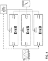
- the converter unit 12 includes three DAB converters (shown in Figure 4 ), each with eight controllable switches, while in other embodiments the converter unit 12 includes two DAB converters.
- the controllable switches of the DAB converters are operated by the controller 16 to provide a DC voltage to a battery 18, despite an unbalanced voltage being present in the three-phase power supply 14.
- the controller 16 provides pulse-width-modulated control signals (depicted as CNTL in Figure 2 ) for driving the individual switches of the DAB converters, for example Si MOSFETS or HEMT switches.
- FIG. 3 A single DAB converter from the converter unit 12 is shown in Figure 3 .
- Figure 3 illustrates an isolated DAB topology in a single-stage AC/DC configuration.
- the isolated DAB topology receives a time varying DC source voltage from a voltage source, for example a rectified AC grid voltage.
- the DC source voltage is provided to an input bridge comprising four primary side switches.
- the output of the input bridge is provided to the primary coil of an isolation transformer.
- the secondary of the isolation transformer delivers an AC output voltage to the output bridge, which comprises four secondary side switches.
- the resulting DC output voltage from the output bridge is provided to a load.
- the DAB is used both as the Power Factor Correction (PFC) stage and the DC output regulation stage, using either a matrix primary configuration or a front-end 120Hz rectifier.
- Each DAB stage includes a three-phase AC/DC system such that one DAB is responsible for PFC of a single AC phase and DC output is achieved through the combination of all three DAB outputs.
- the system shall be considered in application of charging a high-voltage (HV) battery from a three-phase 480 V RMS grid. It should, however, be noted that this is only one possible application, and the present invention can apply to any three-phase AC/DC system where a potential exists for an unbalanced three-phase source and a necessity for a DC output.
- HV high-voltage
- the controller 16 dynamically adapts the power references of the DABs such that their output power is always balanced. This will necessarily come at the expense of a slightly lower grid-side power factor, but the proposed algorithm assumes that DC power output is the higher priority when the grid is already distorted.
- the flow diagram represents a number of method steps performed by the controller 16. That is, the controller 16 includes instructions that, when executed, cause the controller 16 to perform certain method steps in digital logic. These method steps are described below in connection with a voltage detection module 20, a first transformation module 22, a level shift module 24, and a second transformation module 26, each module being resident on the controller 16. Each module is discussed in turn.
- the voltage detection module 20 is adapted to provide voltage component values indicative of the value of the voltage in each phase of the three-phase AC power supply 14.
- the voltage detection module 20 determines a first phase input voltage component (V a ), a second phase input voltage component (V b ), and a third phase input voltage component (V c ) based on concurrent voltage measurements of the three-phase AC power supply 14.
- the voltage values are output as a three-phase voltage vector (V a , V b , V c ).
- the first transformation module 22 is adapted to observe the Phase-Lock-Loop (PLL) outputs from each phase and determine what grid angle most closely describes the three phases by looking for an outlier. Using the selected grid angle, the first transformation module 22 performs a Clarke-Park transformation of the 3-phase grid voltage from the stationary 3-phase (a-b-c) frame to rotating direct-quadrature (d-q) frame.
- PLL Phase-Lock-Loop
- the first transformation module 22 converts the three-phase voltage vector from a stationary reference frame into first and second reference voltage signals (V d , V q ) in a rotating reference frame.
- the first transformation module 22 includes a three-phase PLL algorithm, in which the three-phase voltage vector (V a , V b , V c ) is translated into a rotating reference frame using the Clarke-Park transform.
- the Clarke transform converts the three-phase voltage vector into two phase quantities (V ⁇ , V ⁇ ) in a stationary ⁇ coordinate system.
- the output of the Clarke transform is converted by a Park transform into a d-component value and a q-component value in a rotating reference frame that is defined by a grid angle ⁇ , with the grid angle ⁇ being controlled by the phase-lock-loop.
- the d-component value is zero (V d ) and the q-component value (V q ) depicts the voltage vector amplitude.
- the d-component value is non-zero however.
- the level shift module 24 is then adapted to compensate the d-component value and the q-component value (V d-comp , V q-comp ) such that the d-component value is zero to simulate a perfectly balanced AC voltage, with a marginal reduction in power factor.
- the quadrature-axis voltage V q represents the equivalent amplitude of the active grid voltages
- the direct-axis voltage V d represents the equivalent amplitude of reactive component.
- the required power reference depends only on V q , and as such, V d shall be discarded and set to zero.
- a heavy 120Hz ripple will be present on V q and higher harmonics may be incurred due to a harmonic distortion.
- LPF heavy lowpass filter
- the second transformation module 26 is adapted to reconstruct voltage values in a stationary reference frame.
- the second transformation module 26 is adapted to convert the compensated d-component value and the compensate q-component value (V d-comp , V q-comp ) from the rotating reference frame to the stationary reference frame using an inverse Clarke-Park transform according to the same grid angle ⁇ for the Clarke-Park transform.
- the power error is then added to the power references of the other DABs.
- the second transformation module 26 can apply a zero-watt minimum saturation to the power references if reverse power flow is not permitted. Otherwise, negative power requests are expected.
- the controller 16 is adapted to control operation of the converter unit 12 for providing a DC charging voltage to a battery that is substantially free of fluctuations or ripple.
- the controller 16 can include a converter control module adapted to control operation of a first phase dual active bridge converter, a second phase dual active bridge converter, and a third phase dual active bridge converter based on the output of the second transformation module 26.
- the DC output can be provided substantially ripple-free despite the existence of unbalanced voltage conditions in the electrical grid, with only a slight reduction in power factor, and the current embodiment can be implemented in digital logic with effectively no additional hardware.
- FIG. 6 A model of the forgoing control algorithm is depicted in Figures 6 and 7 , with simulation results being shown in Figure 8 .
- the three-phase voltage vector [Vabc] is provided to a first integrated circuit 30 (or module) for performing the phase lock loop and grid angle selection and is provided to a second integrated circuit 32 (or module) for performing the power balancing algorithm.
- the second integrated circuit 32 also receives, as an input, the output of the first integrated circuit 30 and the power reference [Pout_ref].
- the power reference [Pout_ref] is derived by the controller 16 from an outer control architecture, which takes external commands, overlays them with operation constraints and system states, applies feedback controllers, and calculates the required output from each phase.
- the second integrated circuit 32 uses the virtual grid values [Vabc], [wt] and the power reference [Pout_ref] to calculate the desired input power from each DAB [Pref_a], [Pref_b], [Pref_c] to achieve a balanced output in the manner set forth above. With this information, the appropriate pulse-width-modulated gate signals are sent by a converter control module to the individually controllable switches of the DAB converter(s).
- a logic diagram of the power balancing algorithm performed by the second integrated circuit 32 is depicted in in Figure 7 .
- the input voltage includes a 2% phase shift distortion for a 480V RMS grid with a 7kW per phase power reference and sourcing a 300V DC load. Without power balancing, the phase shift distortion causes an 8A peak-to-peak ripple. With power balancing, the peak-to-peak ripple is reduced to less than 200mA.
Landscapes
- Engineering & Computer Science (AREA)
- Power Engineering (AREA)
- Transportation (AREA)
- Mechanical Engineering (AREA)
- Charge And Discharge Circuits For Batteries Or The Like (AREA)
Abstract
Description
- This application claims the benefit of
U.S. Provisional Application 62/544,358, filed August 11, 2017 - The present invention relates to a control circuit for use with unbalanced grid voltages when recharging vehicle batteries.
- Electric vehicles include a battery for powering an electric drive system. The battery can include multiple battery cells that are rechargeable by a DC voltage. For plug-in electric vehicles, the local electrical grid is used for recharging the battery when the vehicle is not being driven. Because most electrical grids provide a three-phase AC voltage, however, power from the local electrical grid must first be converted into a suitable DC voltage.
- A variety of circuits exist for converting a three-phase AC voltage into a DC voltage. One known circuit is illustrated in
Figure 1 and includes a first stage converter and a second stage converter. The first stage converter receives a DC voltage from a front end rectifier (not shown) and outputs to a DC link capacitor, while the second stage converter provides galvanic isolation for the circuit. The first stage converter in this circuit is a dual-active-bridge (DAB) converter. In operation, its DC input is inverted by a primary-side bridge and rectified by a secondary-side bridge. The DAB converter is typically operated by a controller to regulate the magnitude of the DC output in accordance with battery charging requirements. - In some applications, it is desirable to implement a single stage design. In practice however local electrical grids can provide an unbalanced three-phase AC voltage. If not corrected, an unbalanced voltage can cause voltage distortions or current ripple in the DC output, which may be harmful to the battery during recharging. Existing single stage designs however are poorly suited for applications in which the local electrical grid is unbalanced. Accordingly, there remains a continued need for an improved single stage control circuit for recharging vehicle batteries, and in particular, a single stage control circuit including a DAB converter.
- In accordance with one embodiment, a single stage DAB control circuit for converting an unbalanced grid voltage into a DC voltage is provided. The control circuit includes a controller having a voltage detection module, a first transformation module, a level shift module, and a second transformation module. The voltage detection module provides voltage component values that are indicative of the voltage in each phase of a three-phase AC power supply. The first transformation module converts the voltage component values from a stationary reference frame into reference voltage signals in a rotating reference frame using a Clarke-Park transform. The level shift module compensates the reference voltage signals to simulate an ideal, e.g., balanced, AC voltage. The second transformation module converts the compensated reference voltage signals from the rotating reference frame to the stationary reference frame using an inverse Clarke-Park transform. The controller is then operable to control operation of a single stage DAB converter on the basis of the reconstructed voltage values for providing a DC charging voltage that is substantially free of fluctuations or ripple.
- In accordance with another embodiment, a method for operating a DAB circuit is provided. The method includes determining voltage component values indicative of the value of the voltage in each phase of the three-phase AC power supply and converting the voltage component values from a stationary reference frame into first and second reference voltage signals in a rotating reference frame using a Clarke-Park transform. The method then includes compensating the first and second reference voltage signals to simulate a balanced three-phase AC power supply and converting the compensated first and second reference voltage signals from the rotating reference frame to the stationary reference frame using an inverse Clarke-Park transform to provide a first power reference, a second power reference, and a third power reference. The method further includes controlling operation of a first phase dual active bridge converter, a second phase dual active bridge converter, and a third phase dual active bridge converter based on the first power reference, the second power reference, and the third power reference, respectively, for providing a DC charging voltage to the battery.
- As discussed in greater detail below, the control circuit and method of operation provides a single stage design, optionally for an on-board vehicle charging system, the single stage design compensating for grid disturbances with only a marginal reduction of power factor. The DC output can be provided despite the existence of unbalanced voltage conditions in the electrical grid, and the present invention can be implemented in digital logic with effectively no additional hardware as compared to existing dual stage control circuits.
- These and other features and advantages of the present invention will become apparent from the following description of the invention, when viewed in accordance with the accompanying drawings and appended claims.
-
-
Figure 1 is a prior art control circuit including a first stage converter and a second stage converter for charging a vehicle battery. -
Figure 2 is a schematic diagram of a single stage control circuit for charging a vehicle battery in accordance with an embodiment of the present invention. -
Figure 3 is a schematic diagram of an isolated DAB in a single stage AC/DC configuration. -
Figure 4 is a schematic diagram of a three-phase DAB AC/DC system in a battery charging application in accordance with an embodiment of the present invention. -
Figure 5 is a flow chart of the control scheme used in the single stage control circuit illustrated inFigure 2 . -
Figure 6 depicts a DAB control algorithm in accordance with an embodiment of the present invention. -
Figure 7 depicts a power balancing algorithm in accordance with an embodiment of the present invention. -
Figure 8 are simulation results that depict the output of a 3-phase isolated DAB from an unbalanced 480V grid input to a 300V (DC) output at 7kW per DAB reference. - The embodiment disclosed herein includes a DAB control circuit and a related method of operation. The DAB control circuit is well suited for a single-stage DAB converter and compensates for grid disturbances in an AC grid voltage. As set forth below, the DAB control circuit is operable to control operation of the single-stage DAB converter on the basis of the reconstructed voltage values using a Clarke-Park transform and an inverse Clarke-Park transform. Though described herein in connection with a single-design for vehicle batteries, the DAB control circuit and related method can be used in other applications as desired.
- Referring to
Figure 2 , a single stage DAB control circuit in accordance with one embodiment is illustrated and generally designated 10. Thecontrol circuit 10 includes aconverter unit 12 that is electrically coupled to a three-phase power supply 14. Thecontrol circuit 10 also includes acontroller 16 for providing control signals to theconverter unit 12 depending upon voltage measurements of the three-phase power supply 14. In the current embodiment, theconverter unit 12 includes three DAB converters (shown inFigure 4 ), each with eight controllable switches, while in other embodiments theconverter unit 12 includes two DAB converters. As set forth below, the controllable switches of the DAB converters are operated by thecontroller 16 to provide a DC voltage to abattery 18, despite an unbalanced voltage being present in the three-phase power supply 14. In the current embodiment, thecontroller 16 provides pulse-width-modulated control signals (depicted as CNTL inFigure 2 ) for driving the individual switches of the DAB converters, for example Si MOSFETS or HEMT switches. - A single DAB converter from the
converter unit 12 is shown inFigure 3 . In particular,Figure 3 illustrates an isolated DAB topology in a single-stage AC/DC configuration. As is known in the art, the isolated DAB topology receives a time varying DC source voltage from a voltage source, for example a rectified AC grid voltage. The DC source voltage is provided to an input bridge comprising four primary side switches. The output of the input bridge is provided to the primary coil of an isolation transformer. The secondary of the isolation transformer delivers an AC output voltage to the output bridge, which comprises four secondary side switches. The resulting DC output voltage from the output bridge is provided to a load. The DAB is used both as the Power Factor Correction (PFC) stage and the DC output regulation stage, using either a matrix primary configuration or a front-end 120Hz rectifier. This source will draw power at its input and source power at its output with some efficiency η, such that Pout = η * Pin and controlled by a "Power Reference" command. - Three DAB stages from the
converter unit 12 are shown inFigure 4 . Each DAB stage includes a three-phase AC/DC system such that one DAB is responsible for PFC of a single AC phase and DC output is achieved through the combination of all three DAB outputs. For illustrative purposes, the system shall be considered in application of charging a high-voltage (HV) battery from a three-phase 480VRMS grid. It should, however, be noted that this is only one possible application, and the present invention can apply to any three-phase AC/DC system where a potential exists for an unbalanced three-phase source and a necessity for a DC output. - To rectify the susceptibility of the 3-phase single-stage DAB AC/DC to output ripple due to an imbalanced grid, the
controller 16 dynamically adapts the power references of the DABs such that their output power is always balanced. This will necessarily come at the expense of a slightly lower grid-side power factor, but the proposed algorithm assumes that DC power output is the higher priority when the grid is already distorted. - Referring to
Figure 5 , a flow diagram illustrating operation of thecontroller 16 is illustrated. The flow diagram represents a number of method steps performed by thecontroller 16. That is, thecontroller 16 includes instructions that, when executed, cause thecontroller 16 to perform certain method steps in digital logic. These method steps are described below in connection with avoltage detection module 20, afirst transformation module 22, alevel shift module 24, and asecond transformation module 26, each module being resident on thecontroller 16. Each module is discussed in turn. - The
voltage detection module 20 is adapted to provide voltage component values indicative of the value of the voltage in each phase of the three-phaseAC power supply 14. In particular, thevoltage detection module 20 determines a first phase input voltage component (Va), a second phase input voltage component (Vb), and a third phase input voltage component (Vc) based on concurrent voltage measurements of the three-phaseAC power supply 14. The voltage values are output as a three-phase voltage vector (Va, Vb, Vc). - The
first transformation module 22 is adapted to observe the Phase-Lock-Loop (PLL) outputs from each phase and determine what grid angle most closely describes the three phases by looking for an outlier. Using the selected grid angle, thefirst transformation module 22 performs a Clarke-Park transformation of the 3-phase grid voltage from the stationary 3-phase (a-b-c) frame to rotating direct-quadrature (d-q) frame. - In particular, the
first transformation module 22 converts the three-phase voltage vector from a stationary reference frame into first and second reference voltage signals (Vd, Vq) in a rotating reference frame. Thefirst transformation module 22 includes a three-phase PLL algorithm, in which the three-phase voltage vector (Va, Vb, Vc) is translated into a rotating reference frame using the Clarke-Park transform. The Clarke transform converts the three-phase voltage vector into two phase quantities (Vα, Vβ) in a stationary αβ coordinate system. The output of the Clarke transform is converted by a Park transform into a d-component value and a q-component value in a rotating reference frame that is defined by a grid angle Θ, with the grid angle Θ being controlled by the phase-lock-loop. Under balanced voltage conditions, the d-component value is zero (Vd) and the q-component value (Vq) depicts the voltage vector amplitude. Under unbalanced voltage conditions, the d-component value is non-zero however. - The
level shift module 24 is then adapted to compensate the d-component value and the q-component value (Vd-comp, Vq-comp) such that the d-component value is zero to simulate a perfectly balanced AC voltage, with a marginal reduction in power factor. In the d-q frame, the quadrature-axis voltage Vq represents the equivalent amplitude of the active grid voltages, while the direct-axis voltage Vd represents the equivalent amplitude of reactive component. Thus, the required power reference depends only on Vq, and as such, Vd shall be discarded and set to zero. In the case of a phase or amplitude distortion on the grid, a heavy 120Hz ripple will be present on Vq and higher harmonics may be incurred due to a harmonic distortion. Thus, a heavy lowpass filter (LPF) is applied to find the average value of Vq. Accordingly, by monitoring the output of thefirst transformation module 22, an unbalanced condition can be detected. - The
second transformation module 26 is adapted to reconstruct voltage values in a stationary reference frame. In particular, thesecond transformation module 26 is adapted to convert the compensated d-component value and the compensate q-component value (Vd-comp, Vq-comp) from the rotating reference frame to the stationary reference frame using an inverse Clarke-Park transform according to the same grid angle Θ for the Clarke-Park transform. - More particularly, the
second transformation module 26 uses the virtual grid values to calculate the desired input power from each DAB to achieve balanced output and DC power Pout as
phase is virtual grid phase RMS voltage over one period, and Poutphase is the required average output power per phase such that Poutphase = Pout /3. Thesecond transformation module 26 then uses the virtual grid voltage values to calculate the desired current that Pdesphase would draw from vdesphase as
second transformation module 26 calculates the phase power reference for the DAB using the real phase voltage as Prefphase = videsphase * vgridphase and calculates the difference between the desired power and the power reference and multiplies by a gain of 0.5 to find the power error as
second transformation module 26 can apply a zero-watt minimum saturation to the power references if reverse power flow is not permitted. Otherwise, negative power requests are expected. - As described above, the
controller 16 is adapted to control operation of theconverter unit 12 for providing a DC charging voltage to a battery that is substantially free of fluctuations or ripple. For this purpose, thecontroller 16 can include a converter control module adapted to control operation of a first phase dual active bridge converter, a second phase dual active bridge converter, and a third phase dual active bridge converter based on the output of thesecond transformation module 26. The DC output can be provided substantially ripple-free despite the existence of unbalanced voltage conditions in the electrical grid, with only a slight reduction in power factor, and the current embodiment can be implemented in digital logic with effectively no additional hardware. - A model of the forgoing control algorithm is depicted in
Figures 6 and7 , with simulation results being shown inFigure 8 . As shown inFigure 6 , the three-phase voltage vector [Vabc] is provided to a first integrated circuit 30 (or module) for performing the phase lock loop and grid angle selection and is provided to a second integrated circuit 32 (or module) for performing the power balancing algorithm. The secondintegrated circuit 32 also receives, as an input, the output of the firstintegrated circuit 30 and the power reference [Pout_ref]. The power reference [Pout_ref] is derived by thecontroller 16 from an outer control architecture, which takes external commands, overlays them with operation constraints and system states, applies feedback controllers, and calculates the required output from each phase. The secondintegrated circuit 32 uses the virtual grid values [Vabc], [wt] and the power reference [Pout_ref] to calculate the desired input power from each DAB [Pref_a], [Pref_b], [Pref_c] to achieve a balanced output in the manner set forth above. With this information, the appropriate pulse-width-modulated gate signals are sent by a converter control module to the individually controllable switches of the DAB converter(s). A logic diagram of the power balancing algorithm performed by the secondintegrated circuit 32 is depicted in inFigure 7 . As shown inFigure 8 , the input voltage includes a 2% phase shift distortion for a 480VRMS grid with a 7kW per phase power reference and sourcing a 300VDC load. Without power balancing, the phase shift distortion causes an 8A peak-to-peak ripple. With power balancing, the peak-to-peak ripple is reduced to less than 200mA. - The above description is that of current embodiment of the invention. Various alterations and changes can be made without departing from the spirit and broader aspects of the invention. This disclosure is presented for illustrative purposes and should not be interpreted as an exhaustive description of all embodiments of the invention or to limit the scope of the claims to the specific elements illustrated or described in connection with these embodiments. Any reference to elements in the singular, for example, using the articles "a," "an," "the," or "said," is not to be construed as limiting the element to the singular.
- The following statements are useful for understanding the present invention:
- S1. A control system for converting power from a three-phase AC power supply into DC power for charging a battery, the control system comprising:
- a voltage detection module adapted to provide voltage component values indicative of the value of the voltage in each phase of the three-phase AC power supply;
- a first transformation module and adapted to convert the voltage component values from a stationary reference frame into first and second reference voltage signals in a rotating reference frame using a Clarke-Park transform;
- a level shift module adapted to compensate the first and second reference voltage signals to simulate a balanced three-phase AC power supply;
- a second transformation module adapted to convert the compensated first and second reference voltage signals from the rotating reference frame to the stationary reference frame using an inverse Clarke-Park transform, the second transformation module providing, as an output, a first power reference, a second power reference, and a third power reference; and
- a converter control module adapted to control operation of a first phase dual active bridge converter, a second phase dual active bridge converter, and a third phase dual active bridge converter based on the output of the second transformation module for providing a DC charging voltage to the battery.
- S2. The control system of statement S1 wherein the component voltage values are output as a three-phase voltage vector to an integrated circuit for performing a power balancing algorithm.
- S3. The control system of statement S2 wherein the integrated circuit includes the first transformation module, the level shift module, and the second transformation module.
- S4. The control system of statement S1 wherein the converter control module is adapted to control a plurality of switches of each of the first phase dual active bridge converter, the second phase dual active bridge converter, and the third phase dual active bridge converter.
- S5. The control system of statement S1 wherein the first phase dual active bridge converter, the second phase dual active bridge converter, and the third phase dual active bridge converter constitute a single stage converter for output to the battery.
- S6. The control system of statement S1 wherein the first transformation module includes a three-phase Phase Lock Loop (PLL) algorithm for the conversion of the voltage component values from the stationary reference frame into the rotating reference frame.
- S7. The control system of statement S1 wherein the level shift module is adapted to detect an unbalanced load condition in the three-phase AC power supply based on the output of the first transformation module.
- S8. The control system of statement S1 wherein the second transformation module is adapted to calculate the desired power output from each of the first phase dual active bridge converter, the second phase dual active bridge converter, and the third phase dual active bridge converter.
- S9. The control system of statement S1 wherein the battery is a vehicle battery and wherein the control system constitutes part of an on-board vehicle charging system.
- S10. The control system of statement S1 wherein the first power reference, the second power reference, and the third power reference correspond to the power output of the first phase dual active bridge converter, the second phase dual active bridge converter, and the third phase dual active bridge for a balanced load condition.
- S11. A method for converting power from a three-phase AC power supply into DC power for charging a battery, the method comprising:
- determining voltage component values indicative of the value of the voltage in each phase of the three-phase AC power supply;
- converting the voltage component values from a stationary reference frame into first and second reference voltage signals in a rotating reference frame using a Clarke-Park transform;
- compensating the first and second reference voltage signals to simulate a balanced three-phase AC power supply;
- converting the compensated first and second reference voltage signals from the rotating reference frame to the stationary reference frame using an inverse Clarke-Park transform to provide a first power reference, a second power reference, and a third power reference; and
- controlling operation of a first phase dual active bridge converter, a second phase dual active bridge converter, and a third phase dual active bridge converter based on the first power reference, the second power reference, and the third power reference for providing a DC charging voltage to the battery with substantially no ripple.
- S12. The method of statement S11 wherein the controlling step includes controlling a plurality of switches of each of the first phase dual active bridge converter, the second phase dual active bridge converter, and the third phase dual active bridge converter.
- S13. The method of statement S11 wherein the first phase dual active bridge converter, the second phase dual active bridge converter, and the third phase dual active bridge converter constitute a single stage converter for output to the battery.
- S14. The method of statement S11 wherein converting the voltage component values from a stationary reference frame in the rotating reference frame includes performing a three-phase Phase Lock Loop (PLL) algorithm.
- S15. The method of statement S11 wherein converting the compensated first and second reference voltage signals includes detecting an unbalanced load condition in the three-phase AC power supply.
- S16. The method of statement S11 further including calculating the desired power output from each of the first phase dual active bridge converter, the second phase dual active bridge converter, and the third phase dual active bridge converter.
- S17. A controller for controlling a single stage converter for charging a vehicle battery, the single stage converter including a first phase DAB, a second phase DAB, and a third phase DAB, the controller comprising:
- a voltage detection module adapted to provide voltage component values indicative of the value of the voltage in each phase of a three-phase AC power supply;
- a first transformation module and adapted to convert the voltage component values into first and second reference voltage signals in a rotating reference frame;
- a level shift module adapted to compensate the first and second reference voltage signals to simulate a balanced three-phase AC power supply;
- a second transformation module adapted to convert the compensated first and second reference voltage signals from the rotating reference frame to a stationary reference frame, the second transformation module providing, as an output, a first power reference, a second power reference, and a third power reference; and
- a converter control module adapted to control operation of the first phase DAB, the second phase DAB, and the third phase DAB based on the output of the second transformation module for providing a DC charging voltage to the vehicle battery.
- S18. The controller of statement S17, wherein the first power reference, the second power reference, and the third power reference correspond to the desired power output of the first phase DAB, the second phase DAB, and the third phase DAB, respectively, for a balanced load condition.
- S19. The controller of statement S17 wherein the component voltage values are output as a three-phase voltage vector.
- S20. The controller of statement S17 wherein the controller is adapted to control a plurality of switches of each of the first phase DAB, the second phase DAB, and the third phase DAB.
Claims (15)
- A control system for converting power from a three-phase AC power supply into DC power for charging a battery, the control system comprising:a voltage detection module adapted to provide voltage component values indicative of the value of the voltage in each phase of the three-phase AC power supply;a first transformation module and adapted to convert the voltage component values from a stationary reference frame into first and second reference voltage signals in a rotating reference frame using a Clarke-Park transform;a level shift module adapted to compensate the first and second reference voltage signals to simulate a balanced three-phase AC power supply;a second transformation module adapted to convert the compensated first and second reference voltage signals from the rotating reference frame to the stationary reference frame using an inverse Clarke-Park transform, the second transformation module providing, as an output, a first power reference, a second power reference, and a third power reference; anda converter control module adapted to control operation of a first phase dual active bridge converter, a second phase dual active bridge converter, and a third phase dual active bridge converter based on the output of the second transformation module for providing a DC charging voltage to the battery.
- The control system of claim 1 wherein the component voltage values are output as a three-phase voltage vector to an integrated circuit for performing a power balancing algorithm,
optionally wherein the integrated circuit includes the first transformation module, the level shift module, and the second transformation module. - The control system of claim 1 or claim 2 wherein the converter control module is adapted to control a plurality of switches of each of the first phase dual active bridge converter, the second phase dual active bridge converter, and the third phase dual active bridge converter.
- The control system of any of the preceding claims wherein the first phase dual active bridge converter, the second phase dual active bridge converter, and the third phase dual active bridge converter constitute a single stage converter for output to the battery.
- The control system of any of the preceding claims wherein:the first transformation module includes a three-phase Phase Lock Loop (PLL) algorithm for the conversion of the voltage component values from the stationary reference frame into the rotating reference frame; and/orthe level shift module is adapted to detect an unbalanced load condition in the three-phase AC power supply based on the output of the first transformation module.
- The control system of any of the preceding claims wherein:the second transformation module is adapted to calculate the desired power output from each of the first phase dual active bridge converter, the second phase dual active bridge converter, and the third phase dual active bridge converter; and/orthe battery is a vehicle battery and the control system constitutes part of an on-board vehicle charging system.
- The control system of any of the preceding claims wherein the first power reference, the second power reference, and the third power reference correspond to the power output of the first phase dual active bridge converter, the second phase dual active bridge converter, and the third phase dual active bridge for a balanced load condition.
- A method for converting power from a three-phase AC power supply into DC power for charging a battery, the method comprising:determining voltage component values indicative of the value of the voltage in each phase of the three-phase AC power supply;converting the voltage component values from a stationary reference frame into first and second reference voltage signals in a rotating reference frame using a Clarke-Park transform;compensating the first and second reference voltage signals to simulate a balanced three-phase AC power supply;converting the compensated first and second reference voltage signals from the rotating reference frame to the stationary reference frame using an inverse Clarke-Park transform to provide a first power reference, a second power reference, and a third power reference; andcontrolling operation of a first phase dual active bridge converter, a second phase dual active bridge converter, and a third phase dual active bridge converter based on the first power reference, the second power reference, and the third power reference for providing a DC charging voltage to the battery with substantially no ripple.
- The method of claim 8 wherein the controlling step includes controlling a plurality of switches of each of the first phase dual active bridge converter, the second phase dual active bridge converter, and the third phase dual active bridge converter.
- The method of claim 8 or claim 9 wherein the first phase dual active bridge converter, the second phase dual active bridge converter, and the third phase dual active bridge converter constitute a single stage converter for output to the battery.
- The method of any of claims 8 to 10 wherein:converting the voltage component values from a stationary reference frame in the rotating reference frame includes performing a three-phase Phase Lock Loop (PLL) algorithm; and/orconverting the compensated first and second reference voltage signals includes detecting an unbalanced load condition in the three-phase AC power supply.
- The method of any of claims 8 to 11 further including calculating the desired power output from each of the first phase dual active bridge converter, the second phase dual active bridge converter, and the third phase dual active bridge converter.
- A controller for controlling a single stage converter for charging a vehicle battery, the single stage converter including a first phase DAB, a second phase DAB, and a third phase DAB, the controller comprising:a voltage detection module adapted to provide voltage component values indicative of the value of the voltage in each phase of a three-phase AC power supply;a first transformation module and adapted to convert the voltage component values into first and second reference voltage signals in a rotating reference frame;a level shift module adapted to compensate the first and second reference voltage signals to simulate a balanced three-phase AC power supply;a second transformation module adapted to convert the compensated first and second reference voltage signals from the rotating reference frame to a stationary reference frame, the second transformation module providing, as an output, a first power reference, a second power reference, and a third power reference; anda converter control module adapted to control operation of the first phase DAB, the second phase DAB, and the third phase DAB based on the output of the second transformation module for providing a DC charging voltage to the vehicle battery.
- The controller of claim 13, wherein the first power reference, the second power reference, and the third power reference correspond to the desired power output of the first phase DAB, the second phase DAB, and the third phase DAB, respectively, for a balanced load condition.
- The controller of claim 13 or claim 14 wherein:the component voltage values are output as a three-phase voltage vector; and/orthe controller is adapted to control a plurality of switches of each of the first phase DAB, the second phase DAB, and the third phase DAB.
Applications Claiming Priority (1)
| Application Number | Priority Date | Filing Date | Title |
|---|---|---|---|
| US201762544358P | 2017-08-11 | 2017-08-11 |
Publications (2)
| Publication Number | Publication Date |
|---|---|
| EP3442089A1 true EP3442089A1 (en) | 2019-02-13 |
| EP3442089B1 EP3442089B1 (en) | 2020-06-17 |
Family
ID=63113363
Family Applications (1)
| Application Number | Title | Priority Date | Filing Date |
|---|---|---|---|
| EP18186605.4A Active EP3442089B1 (en) | 2017-08-11 | 2018-07-31 | Dual active bridge control circuit for use with unbalanced grid voltages |
Country Status (3)
| Country | Link |
|---|---|
| US (1) | US10491132B2 (en) |
| EP (1) | EP3442089B1 (en) |
| CN (1) | CN109391017B (en) |
Cited By (4)
| Publication number | Priority date | Publication date | Assignee | Title |
|---|---|---|---|---|
| CN113972673A (en) * | 2021-09-29 | 2022-01-25 | 国网山东省电力公司营销服务中心(计量中心) | Intelligent perception inspection system for transformer area line loss |
| CN114884385A (en) * | 2022-05-26 | 2022-08-09 | 上海交通大学 | Double-active-bridge micro inverter and peak current control method and system |
| CN116424122A (en) * | 2023-06-07 | 2023-07-14 | 北京坐骑科技有限公司 | Universal On-Board Charger for Electric Vehicles |
| CN117360275A (en) * | 2020-09-30 | 2024-01-09 | 阿尔法能源技术公司 | Systems, devices and methods for intra- and inter-phase balancing in module-based cascaded energy systems |
Families Citing this family (6)
| Publication number | Priority date | Publication date | Assignee | Title |
|---|---|---|---|---|
| GB2552777B (en) * | 2016-07-21 | 2022-06-08 | Petalite Ltd | A battery charging system and method |
| EP4128477A4 (en) * | 2020-04-26 | 2023-05-03 | Huawei Technologies Co., Ltd. | POWER SUPPLY AND DISTRIBUTION SYSTEM |
| CN112098766B (en) * | 2020-11-09 | 2021-02-19 | 西南交通大学 | On-line evaluation method of multi-mode cascade DAB power fluctuation based on differential fitting |
| US20250317002A1 (en) * | 2022-05-19 | 2025-10-09 | The Texas A&M University System | Technologies for dual-stage charge collection and energy storage for alternative energy sources |
| CN115800766B (en) * | 2023-01-30 | 2023-05-05 | 广东电网有限责任公司肇庆供电局 | Model reference self-adaptive control method and device based on double active bridge converters |
| CN122203325B (en) * | 2026-05-15 | 2026-07-24 | 南京德睿特来电能源研究院有限公司 | A method, device and system for three-phase imbalance compensation control of DC charging piles |
Citations (4)
| Publication number | Priority date | Publication date | Assignee | Title |
|---|---|---|---|---|
| EP2003758A1 (en) * | 2007-06-15 | 2008-12-17 | Hitachi Appliances, Inc. | Power conversion apparatus and module including the power conversion apparatus |
| US20090244937A1 (en) * | 2008-03-28 | 2009-10-01 | American Superconductor Corporation | Dc bus voltage harmonics reduction |
| US20110134669A1 (en) * | 2009-12-07 | 2011-06-09 | Kyosan Electric Mfg. Co., Ltd. | Unbalanced voltage compensation method, unbalanced voltage compensator, three-phase converter control method, and controller of three-phase converter |
| US20130307486A1 (en) * | 2012-05-17 | 2013-11-21 | Delta Electronics, Inc. | Charging system |
Family Cites Families (12)
| Publication number | Priority date | Publication date | Assignee | Title |
|---|---|---|---|---|
| US5283727A (en) * | 1992-09-16 | 1994-02-01 | General Electric Company | Independent control of the AC line current and output DC voltage of a high power factor AC-to-DC converter |
| AU2003256296B2 (en) * | 2002-07-31 | 2008-04-03 | Smc Electrical Products, Inc. | Low voltage, two-level, six-pulse induction motor controller driving a medium-to-high voltage, three-or-more-level AC drive inverter bridge |
| GB0625121D0 (en) * | 2006-12-18 | 2007-01-24 | Gendrive Ltd | Electrical energy converter |
| US7710082B2 (en) * | 2007-10-18 | 2010-05-04 | Instituto Potosino De Investigacion Cientifica Y Technologica (Ipicyt) | Controller for the three-phase cascade multilevel converter used as shunt active filter in unbalanced operation with guaranteed capacitors voltages balance |
| US8183820B2 (en) * | 2008-07-21 | 2012-05-22 | GM Global Technology Operations LLC | Power processing systems and methods for use in plug-in electric vehicles |
| US8014181B2 (en) * | 2009-09-29 | 2011-09-06 | General Electric Company | Power conversion control system |
| US9754300B2 (en) * | 2010-02-18 | 2017-09-05 | University Of Delaware | Electric vehicle station equipment for grid-integrated vehicles |
| GB201114868D0 (en) * | 2011-08-30 | 2011-10-12 | Rolls Royce Plc | Method of controlling an inverter and a controller for controlling an inverter |
| HUE031425T2 (en) * | 2012-06-07 | 2017-07-28 | Gabor Farkas | Regulatory procedure, control device and mobile electric energy storage device |
| CN105684282B (en) * | 2013-11-12 | 2019-05-31 | 坎里格钻探技术有限公司 | Field weakening control of magneto drive |
| CN103731062A (en) * | 2013-12-23 | 2014-04-16 | 华中科技大学 | Control method of AC/DC two-way power converter used for AC/DC hybrid micro-grid |
| US9614461B2 (en) * | 2014-12-02 | 2017-04-04 | Princeton Power Systems, Inc. | Bidirectional high frequency variable speed drive for CHP (combined heating and power) and flywheel applications |
-
2018
- 2018-07-31 EP EP18186605.4A patent/EP3442089B1/en active Active
- 2018-08-10 US US16/100,286 patent/US10491132B2/en active Active
- 2018-08-10 CN CN201810907953.4A patent/CN109391017B/en active Active
Patent Citations (4)
| Publication number | Priority date | Publication date | Assignee | Title |
|---|---|---|---|---|
| EP2003758A1 (en) * | 2007-06-15 | 2008-12-17 | Hitachi Appliances, Inc. | Power conversion apparatus and module including the power conversion apparatus |
| US20090244937A1 (en) * | 2008-03-28 | 2009-10-01 | American Superconductor Corporation | Dc bus voltage harmonics reduction |
| US20110134669A1 (en) * | 2009-12-07 | 2011-06-09 | Kyosan Electric Mfg. Co., Ltd. | Unbalanced voltage compensation method, unbalanced voltage compensator, three-phase converter control method, and controller of three-phase converter |
| US20130307486A1 (en) * | 2012-05-17 | 2013-11-21 | Delta Electronics, Inc. | Charging system |
Cited By (5)
| Publication number | Priority date | Publication date | Assignee | Title |
|---|---|---|---|---|
| CN117360275A (en) * | 2020-09-30 | 2024-01-09 | 阿尔法能源技术公司 | Systems, devices and methods for intra- and inter-phase balancing in module-based cascaded energy systems |
| CN113972673A (en) * | 2021-09-29 | 2022-01-25 | 国网山东省电力公司营销服务中心(计量中心) | Intelligent perception inspection system for transformer area line loss |
| CN113972673B (en) * | 2021-09-29 | 2023-09-22 | 国网山东省电力公司营销服务中心(计量中心) | An intelligent sensing and inspection system for line losses in Taiwan area |
| CN114884385A (en) * | 2022-05-26 | 2022-08-09 | 上海交通大学 | Double-active-bridge micro inverter and peak current control method and system |
| CN116424122A (en) * | 2023-06-07 | 2023-07-14 | 北京坐骑科技有限公司 | Universal On-Board Charger for Electric Vehicles |
Also Published As
| Publication number | Publication date |
|---|---|
| US10491132B2 (en) | 2019-11-26 |
| CN109391017A (en) | 2019-02-26 |
| EP3442089B1 (en) | 2020-06-17 |
| CN109391017B (en) | 2023-04-28 |
| US20190052182A1 (en) | 2019-02-14 |
Similar Documents
| Publication | Publication Date | Title |
|---|---|---|
| US10491132B2 (en) | Dual active bridge control circuit for use with unbalanced grid voltages | |
| EP3734828B1 (en) | Power conversion device | |
| EP3522355B1 (en) | Control device for direct power converter | |
| EP3220531B1 (en) | Power conversion device | |
| US7940537B2 (en) | Partial regeneration in a multi-level power inverter | |
| US9584047B2 (en) | Bidirectional power converter having a charger and export modes of operation | |
| US7088601B2 (en) | Power conversion apparatus and methods using DC bus shifting | |
| EP3048718A1 (en) | Power conversion device | |
| US9871462B2 (en) | Regenerative variable frequency drive with auxiliary power supply | |
| US20170310235A1 (en) | Direct-power-converter control device | |
| AU2009228245A1 (en) | DC bus voltage harmonics reduction | |
| EP4089898A1 (en) | Power module and method for controlling the same, three-phase power system and method for controlling the same | |
| US12294295B2 (en) | Systems and methods of unwanted harmonic content removal for power conversion | |
| US20180294740A1 (en) | Power converter | |
| US20080088291A1 (en) | Electric power converter apparatus | |
| Tang et al. | DQ reference frame modeling and control of single-phase active power decoupling circuits | |
| US20160118904A1 (en) | Power conversion apparatus | |
| EP2728723A1 (en) | Operation of multichannel active rectifier | |
| KR102180900B1 (en) | A method of controlling a three-phase rectifier for a charging device mounted on an electric or hybrid vehicle | |
| CN115954924A (en) | A multi-port flexible loop closing switch and its control method | |
| US10998733B2 (en) | Power conversion system and associated control method | |
| KR102627065B1 (en) | Modular plug-in power decoupling circuit that directly replaces electrolytic capacitors | |
| Xiang et al. | An improved proportional pulse compensation strategy for DC voltage balance of cascaded H-Bridge Rectifier | |
| Lee et al. | DC link voltage controller for three phase vienna rectifier with compensated load current and duty | |
| You et al. | An integrated electrolytic capacitorless onboard charger for electric vehicles |
Legal Events
| Date | Code | Title | Description |
|---|---|---|---|
| PUAI | Public reference made under article 153(3) epc to a published international application that has entered the european phase |
Free format text: ORIGINAL CODE: 0009012 |
|
| STAA | Information on the status of an ep patent application or granted ep patent |
Free format text: STATUS: THE APPLICATION HAS BEEN PUBLISHED |
|
| AK | Designated contracting states |
Kind code of ref document: A1 Designated state(s): AL AT BE BG CH CY CZ DE DK EE ES FI FR GB GR HR HU IE IS IT LI LT LU LV MC MK MT NL NO PL PT RO RS SE SI SK SM TR |
|
| AX | Request for extension of the european patent |
Extension state: BA ME |
|
| STAA | Information on the status of an ep patent application or granted ep patent |
Free format text: STATUS: REQUEST FOR EXAMINATION WAS MADE |
|
| 17P | Request for examination filed |
Effective date: 20190521 |
|
| RBV | Designated contracting states (corrected) |
Designated state(s): AL AT BE BG CH CY CZ DE DK EE ES FI FR GB GR HR HU IE IS IT LI LT LU LV MC MK MT NL NO PL PT RO RS SE SI SK SM TR |
|
| GRAP | Despatch of communication of intention to grant a patent |
Free format text: ORIGINAL CODE: EPIDOSNIGR1 |
|
| STAA | Information on the status of an ep patent application or granted ep patent |
Free format text: STATUS: GRANT OF PATENT IS INTENDED |
|
| RIC1 | Information provided on ipc code assigned before grant |
Ipc: H02M 7/5387 20070101ALI20190823BHEP Ipc: H02J 7/02 20160101AFI20190823BHEP Ipc: H02M 1/00 20060101ALN20190823BHEP Ipc: H02J 7/00 20060101ALN20190823BHEP Ipc: H02M 1/14 20060101ALI20190823BHEP Ipc: H02M 7/217 20060101ALI20190823BHEP Ipc: H02J 3/26 20060101ALI20190823BHEP Ipc: H02M 7/23 20060101ALI20190823BHEP Ipc: H02J 1/10 20060101ALI20190823BHEP Ipc: H02M 5/14 20060101ALI20190823BHEP Ipc: B60L 53/22 20190101ALI20190823BHEP Ipc: H02M 3/335 20060101ALI20190823BHEP Ipc: B60L 53/14 20190101ALI20190823BHEP |
|
| INTG | Intention to grant announced |
Effective date: 20191001 |
|
| GRAJ | Information related to disapproval of communication of intention to grant by the applicant or resumption of examination proceedings by the epo deleted |
Free format text: ORIGINAL CODE: EPIDOSDIGR1 |
|
| STAA | Information on the status of an ep patent application or granted ep patent |
Free format text: STATUS: REQUEST FOR EXAMINATION WAS MADE |
|
| REG | Reference to a national code |
Ref country code: DE Ref legal event code: R079 Ref document number: 602018005316 Country of ref document: DE Free format text: PREVIOUS MAIN CLASS: H02J0003260000 Ipc: H02J0007020000 |
|
| GRAJ | Information related to disapproval of communication of intention to grant by the applicant or resumption of examination proceedings by the epo deleted |
Free format text: ORIGINAL CODE: EPIDOSDIGR1 |
|
| STAA | Information on the status of an ep patent application or granted ep patent |
Free format text: STATUS: GRANT OF PATENT IS INTENDED |
|
| GRAP | Despatch of communication of intention to grant a patent |
Free format text: ORIGINAL CODE: EPIDOSNIGR1 |
|
| INTG | Intention to grant announced |
Effective date: 20200124 |
|
| RIC1 | Information provided on ipc code assigned before grant |
Ipc: B60L 53/22 20190101ALI20200115BHEP Ipc: H02M 5/14 20060101ALI20200115BHEP Ipc: B60L 53/14 20190101ALI20200115BHEP Ipc: H02J 3/26 20060101ALI20200115BHEP Ipc: H02M 7/5387 20070101ALI20200115BHEP Ipc: H02M 3/335 20060101ALI20200115BHEP Ipc: H02M 1/14 20060101ALI20200115BHEP Ipc: H02J 7/00 20060101ALN20200115BHEP Ipc: H02J 1/10 20060101ALI20200115BHEP Ipc: H02M 1/00 20060101ALN20200115BHEP Ipc: H02M 7/23 20060101ALI20200115BHEP Ipc: H02J 7/02 20160101AFI20200115BHEP Ipc: H02M 7/217 20060101ALI20200115BHEP |
|
| GRAS | Grant fee paid |
Free format text: ORIGINAL CODE: EPIDOSNIGR3 |
|
| GRAA | (expected) grant |
Free format text: ORIGINAL CODE: 0009210 |
|
| STAA | Information on the status of an ep patent application or granted ep patent |
Free format text: STATUS: THE PATENT HAS BEEN GRANTED |
|
| AK | Designated contracting states |
Kind code of ref document: B1 Designated state(s): AL AT BE BG CH CY CZ DE DK EE ES FI FR GB GR HR HU IE IS IT LI LT LU LV MC MK MT NL NO PL PT RO RS SE SI SK SM TR |
|
| REG | Reference to a national code |
Ref country code: GB Ref legal event code: FG4D |
|
| REG | Reference to a national code |
Ref country code: CH Ref legal event code: EP |
|
| REG | Reference to a national code |
Ref country code: IE Ref legal event code: FG4D |
|
| REG | Reference to a national code |
Ref country code: DE Ref legal event code: R096 Ref document number: 602018005316 Country of ref document: DE |
|
| REG | Reference to a national code |
Ref country code: AT Ref legal event code: REF Ref document number: 1282533 Country of ref document: AT Kind code of ref document: T Effective date: 20200715 |
|
| PG25 | Lapsed in a contracting state [announced via postgrant information from national office to epo] |
Ref country code: NO Free format text: LAPSE BECAUSE OF FAILURE TO SUBMIT A TRANSLATION OF THE DESCRIPTION OR TO PAY THE FEE WITHIN THE PRESCRIBED TIME-LIMIT Effective date: 20200917 Ref country code: SE Free format text: LAPSE BECAUSE OF FAILURE TO SUBMIT A TRANSLATION OF THE DESCRIPTION OR TO PAY THE FEE WITHIN THE PRESCRIBED TIME-LIMIT Effective date: 20200617 Ref country code: FI Free format text: LAPSE BECAUSE OF FAILURE TO SUBMIT A TRANSLATION OF THE DESCRIPTION OR TO PAY THE FEE WITHIN THE PRESCRIBED TIME-LIMIT Effective date: 20200617 Ref country code: GR Free format text: LAPSE BECAUSE OF FAILURE TO SUBMIT A TRANSLATION OF THE DESCRIPTION OR TO PAY THE FEE WITHIN THE PRESCRIBED TIME-LIMIT Effective date: 20200918 Ref country code: LT Free format text: LAPSE BECAUSE OF FAILURE TO SUBMIT A TRANSLATION OF THE DESCRIPTION OR TO PAY THE FEE WITHIN THE PRESCRIBED TIME-LIMIT Effective date: 20200617 |
|
| REG | Reference to a national code |
Ref country code: LT Ref legal event code: MG4D |
|
| REG | Reference to a national code |
Ref country code: NL Ref legal event code: MP Effective date: 20200617 |
|
| PG25 | Lapsed in a contracting state [announced via postgrant information from national office to epo] |
Ref country code: HR Free format text: LAPSE BECAUSE OF FAILURE TO SUBMIT A TRANSLATION OF THE DESCRIPTION OR TO PAY THE FEE WITHIN THE PRESCRIBED TIME-LIMIT Effective date: 20200617 Ref country code: RS Free format text: LAPSE BECAUSE OF FAILURE TO SUBMIT A TRANSLATION OF THE DESCRIPTION OR TO PAY THE FEE WITHIN THE PRESCRIBED TIME-LIMIT Effective date: 20200617 Ref country code: LV Free format text: LAPSE BECAUSE OF FAILURE TO SUBMIT A TRANSLATION OF THE DESCRIPTION OR TO PAY THE FEE WITHIN THE PRESCRIBED TIME-LIMIT Effective date: 20200617 Ref country code: BG Free format text: LAPSE BECAUSE OF FAILURE TO SUBMIT A TRANSLATION OF THE DESCRIPTION OR TO PAY THE FEE WITHIN THE PRESCRIBED TIME-LIMIT Effective date: 20200917 |
|
| REG | Reference to a national code |
Ref country code: AT Ref legal event code: MK05 Ref document number: 1282533 Country of ref document: AT Kind code of ref document: T Effective date: 20200617 |
|
| PG25 | Lapsed in a contracting state [announced via postgrant information from national office to epo] |
Ref country code: NL Free format text: LAPSE BECAUSE OF FAILURE TO SUBMIT A TRANSLATION OF THE DESCRIPTION OR TO PAY THE FEE WITHIN THE PRESCRIBED TIME-LIMIT Effective date: 20200617 Ref country code: AL Free format text: LAPSE BECAUSE OF FAILURE TO SUBMIT A TRANSLATION OF THE DESCRIPTION OR TO PAY THE FEE WITHIN THE PRESCRIBED TIME-LIMIT Effective date: 20200617 |
|
| PG25 | Lapsed in a contracting state [announced via postgrant information from national office to epo] |
Ref country code: SM Free format text: LAPSE BECAUSE OF FAILURE TO SUBMIT A TRANSLATION OF THE DESCRIPTION OR TO PAY THE FEE WITHIN THE PRESCRIBED TIME-LIMIT Effective date: 20200617 Ref country code: EE Free format text: LAPSE BECAUSE OF FAILURE TO SUBMIT A TRANSLATION OF THE DESCRIPTION OR TO PAY THE FEE WITHIN THE PRESCRIBED TIME-LIMIT Effective date: 20200617 Ref country code: ES Free format text: LAPSE BECAUSE OF FAILURE TO SUBMIT A TRANSLATION OF THE DESCRIPTION OR TO PAY THE FEE WITHIN THE PRESCRIBED TIME-LIMIT Effective date: 20200617 Ref country code: PT Free format text: LAPSE BECAUSE OF FAILURE TO SUBMIT A TRANSLATION OF THE DESCRIPTION OR TO PAY THE FEE WITHIN THE PRESCRIBED TIME-LIMIT Effective date: 20201019 Ref country code: AT Free format text: LAPSE BECAUSE OF FAILURE TO SUBMIT A TRANSLATION OF THE DESCRIPTION OR TO PAY THE FEE WITHIN THE PRESCRIBED TIME-LIMIT Effective date: 20200617 Ref country code: RO Free format text: LAPSE BECAUSE OF FAILURE TO SUBMIT A TRANSLATION OF THE DESCRIPTION OR TO PAY THE FEE WITHIN THE PRESCRIBED TIME-LIMIT Effective date: 20200617 Ref country code: CZ Free format text: LAPSE BECAUSE OF FAILURE TO SUBMIT A TRANSLATION OF THE DESCRIPTION OR TO PAY THE FEE WITHIN THE PRESCRIBED TIME-LIMIT Effective date: 20200617 |
|
| PG25 | Lapsed in a contracting state [announced via postgrant information from national office to epo] |
Ref country code: SK Free format text: LAPSE BECAUSE OF FAILURE TO SUBMIT A TRANSLATION OF THE DESCRIPTION OR TO PAY THE FEE WITHIN THE PRESCRIBED TIME-LIMIT Effective date: 20200617 Ref country code: PL Free format text: LAPSE BECAUSE OF FAILURE TO SUBMIT A TRANSLATION OF THE DESCRIPTION OR TO PAY THE FEE WITHIN THE PRESCRIBED TIME-LIMIT Effective date: 20200617 Ref country code: IS Free format text: LAPSE BECAUSE OF FAILURE TO SUBMIT A TRANSLATION OF THE DESCRIPTION OR TO PAY THE FEE WITHIN THE PRESCRIBED TIME-LIMIT Effective date: 20201017 |
|
| REG | Reference to a national code |
Ref country code: DE Ref legal event code: R097 Ref document number: 602018005316 Country of ref document: DE |
|
| PG25 | Lapsed in a contracting state [announced via postgrant information from national office to epo] |
Ref country code: MC Free format text: LAPSE BECAUSE OF FAILURE TO SUBMIT A TRANSLATION OF THE DESCRIPTION OR TO PAY THE FEE WITHIN THE PRESCRIBED TIME-LIMIT Effective date: 20200617 |
|
| PLBE | No opposition filed within time limit |
Free format text: ORIGINAL CODE: 0009261 |
|
| STAA | Information on the status of an ep patent application or granted ep patent |
Free format text: STATUS: NO OPPOSITION FILED WITHIN TIME LIMIT |
|
| REG | Reference to a national code |
Ref country code: BE Ref legal event code: MM Effective date: 20200731 |
|
| PG25 | Lapsed in a contracting state [announced via postgrant information from national office to epo] |
Ref country code: LU Free format text: LAPSE BECAUSE OF NON-PAYMENT OF DUE FEES Effective date: 20200731 Ref country code: DK Free format text: LAPSE BECAUSE OF FAILURE TO SUBMIT A TRANSLATION OF THE DESCRIPTION OR TO PAY THE FEE WITHIN THE PRESCRIBED TIME-LIMIT Effective date: 20200617 |
|
| 26N | No opposition filed |
Effective date: 20210318 |
|
| PG25 | Lapsed in a contracting state [announced via postgrant information from national office to epo] |
Ref country code: SI Free format text: LAPSE BECAUSE OF FAILURE TO SUBMIT A TRANSLATION OF THE DESCRIPTION OR TO PAY THE FEE WITHIN THE PRESCRIBED TIME-LIMIT Effective date: 20200617 Ref country code: BE Free format text: LAPSE BECAUSE OF NON-PAYMENT OF DUE FEES Effective date: 20200731 |
|
| PG25 | Lapsed in a contracting state [announced via postgrant information from national office to epo] |
Ref country code: IE Free format text: LAPSE BECAUSE OF NON-PAYMENT OF DUE FEES Effective date: 20200731 |
|
| REG | Reference to a national code |
Ref country code: CH Ref legal event code: PL |
|
| PG25 | Lapsed in a contracting state [announced via postgrant information from national office to epo] |
Ref country code: LI Free format text: LAPSE BECAUSE OF NON-PAYMENT OF DUE FEES Effective date: 20210731 Ref country code: CH Free format text: LAPSE BECAUSE OF NON-PAYMENT OF DUE FEES Effective date: 20210731 |
|
| PG25 | Lapsed in a contracting state [announced via postgrant information from national office to epo] |
Ref country code: TR Free format text: LAPSE BECAUSE OF FAILURE TO SUBMIT A TRANSLATION OF THE DESCRIPTION OR TO PAY THE FEE WITHIN THE PRESCRIBED TIME-LIMIT Effective date: 20200617 Ref country code: MT Free format text: LAPSE BECAUSE OF FAILURE TO SUBMIT A TRANSLATION OF THE DESCRIPTION OR TO PAY THE FEE WITHIN THE PRESCRIBED TIME-LIMIT Effective date: 20200617 Ref country code: CY Free format text: LAPSE BECAUSE OF FAILURE TO SUBMIT A TRANSLATION OF THE DESCRIPTION OR TO PAY THE FEE WITHIN THE PRESCRIBED TIME-LIMIT Effective date: 20200617 |
|
| PG25 | Lapsed in a contracting state [announced via postgrant information from national office to epo] |
Ref country code: MK Free format text: LAPSE BECAUSE OF FAILURE TO SUBMIT A TRANSLATION OF THE DESCRIPTION OR TO PAY THE FEE WITHIN THE PRESCRIBED TIME-LIMIT Effective date: 20200617 |
|
| GBPC | Gb: european patent ceased through non-payment of renewal fee |
Effective date: 20220731 |
|
| PG25 | Lapsed in a contracting state [announced via postgrant information from national office to epo] |
Ref country code: GB Free format text: LAPSE BECAUSE OF NON-PAYMENT OF DUE FEES Effective date: 20220731 |
|
| PGFP | Annual fee paid to national office [announced via postgrant information from national office to epo] |
Ref country code: DE Payment date: 20250618 Year of fee payment: 8 |
|
| PGFP | Annual fee paid to national office [announced via postgrant information from national office to epo] |
Ref country code: IT Payment date: 20250626 Year of fee payment: 8 |
|
| PGFP | Annual fee paid to national office [announced via postgrant information from national office to epo] |
Ref country code: FR Payment date: 20260629 Year of fee payment: 9 |