EP3442087A1 - Method for ac arc fault detection using multidimensional energy points - Google Patents
Method for ac arc fault detection using multidimensional energy points Download PDFInfo
- Publication number
- EP3442087A1 EP3442087A1 EP18180028.5A EP18180028A EP3442087A1 EP 3442087 A1 EP3442087 A1 EP 3442087A1 EP 18180028 A EP18180028 A EP 18180028A EP 3442087 A1 EP3442087 A1 EP 3442087A1
- Authority
- EP
- European Patent Office
- Prior art keywords
- hand
- energy summation
- summation value
- hand energy
- arc
- Prior art date
- Legal status (The legal status is an assumption and is not a legal conclusion. Google has not performed a legal analysis and makes no representation as to the accuracy of the status listed.)
- Granted
Links
Images






Classifications
-
- G—PHYSICS
- G01—MEASURING; TESTING
- G01R—MEASURING ELECTRIC VARIABLES; MEASURING MAGNETIC VARIABLES
- G01R31/00—Arrangements for testing electric properties; Arrangements for locating electric faults; Arrangements for electrical testing characterised by what is being tested not provided for elsewhere
- G01R31/50—Testing of electric apparatus, lines, cables or components for short-circuits, continuity, leakage current or incorrect line connections
- G01R31/52—Testing for short-circuits, leakage current or ground faults
-
- G—PHYSICS
- G01—MEASURING; TESTING
- G01R—MEASURING ELECTRIC VARIABLES; MEASURING MAGNETIC VARIABLES
- G01R31/00—Arrangements for testing electric properties; Arrangements for locating electric faults; Arrangements for electrical testing characterised by what is being tested not provided for elsewhere
- G01R31/12—Testing dielectric strength or breakdown voltage ; Testing or monitoring effectiveness or level of insulation, e.g. of a cable or of an apparatus, for example using partial discharge measurements; Electrostatic testing
- G01R31/1227—Testing dielectric strength or breakdown voltage ; Testing or monitoring effectiveness or level of insulation, e.g. of a cable or of an apparatus, for example using partial discharge measurements; Electrostatic testing of components, parts or materials
- G01R31/1263—Testing dielectric strength or breakdown voltage ; Testing or monitoring effectiveness or level of insulation, e.g. of a cable or of an apparatus, for example using partial discharge measurements; Electrostatic testing of components, parts or materials of solid or fluid materials, e.g. insulation films, bulk material; of semiconductors or LV electronic components or parts; of cable, line or wire insulation
- G01R31/1272—Testing dielectric strength or breakdown voltage ; Testing or monitoring effectiveness or level of insulation, e.g. of a cable or of an apparatus, for example using partial discharge measurements; Electrostatic testing of components, parts or materials of solid or fluid materials, e.g. insulation films, bulk material; of semiconductors or LV electronic components or parts; of cable, line or wire insulation of cable, line or wire insulation, e.g. using partial discharge measurements
-
- H—ELECTRICITY
- H02—GENERATION; CONVERSION OR DISTRIBUTION OF ELECTRIC POWER
- H02H—EMERGENCY PROTECTIVE CIRCUIT ARRANGEMENTS
- H02H1/00—Details of emergency protective circuit arrangements
- H02H1/0007—Details of emergency protective circuit arrangements concerning the detecting means
- H02H1/0015—Using arc detectors
Definitions
- the present invention relates generally to the detection of electrical arc faults, and more particularly to a method of AC arc fault detection that uses multidimensional energy points.
- This invention relates to identification of electrical arc faults and, more particularly, to a method for identifying the occurrence of AC arc events.
- An arc fault is a high power discharge of electricity between two or more conductors. This discharge translates into heat, which can break down the wire insulation and possibly trigger an electrical fire.
- Common causes of arc faults include faulty connections due to corrosion, and degradation of electrical wiring, equipment, and related interconnections due to temperature, humidity, vibration, or other environmental conditions. In some cases degradation is simply due to aging of components over a period of time.
- Prior art methods for detecting AC arc faults have relied upon an analysis of disturbances in the "current" signal.
- the present invention provides an improved method of AC arc fault detection that relies upon an analysis of the "voltage" signal to detect an arc fault.
- a method for detecting arc faults in an AC circuit comprising: (a) measuring an AC voltage signal to obtain one cycle of the AC voltage signal; (b) obtaining a left-hand energy summation value and a right-hand energy summation value from the measured AC voltage signal, wherein the left-hand energy summation value is determined by summing left-hand energy values left of a zero-crossing and the right-hand energy summation value is determined by summing right-hand energy values right of the zero-crossing; (c) obtaining a differential left-hand energy summation value and a differential right-hand energy summation value, wherein the differential left-hand energy summation value and differential right-hand energy summation value respectively indicate changes in the left-hand energy summation value and the right-hand energy summation value; (d) obtaining a total energy summation value, wherein the total energy summation value is a sum of the left-hand energy summation value and the right-
- An advantage of the present invention is the provision of an AC arc fault detection method that relies upon an analysis of a voltage signal to detect an arc fault.
- Another advantage of the present invention is the provision of an AC arc fault detection method that is fast, reliable, and accurate.
- a still further advantage of the present invention is the provision of an AC arc fault detection method that reduces the time need to detect an AC arc fault.
- FIG. 1 is a flow chart of an arc fault detection algorithm 5, according to an embodiment of the present invention
- FIG. 2 is a flow chart of a subprocess of arc fault detection algorithm 5
- FIG. 3 illustrates an example circuit 2 where an arc fault is detected using arc fault detection algorithm 5.
- Circuit 2 is comprised of an AC power supply 80, a voltage divider 82, an air gap 84, and a load 86.
- Computer 90 is programmed to operate in accordance with arc fault detection algorithm 5 described in detail below.
- Voltage data is acquired by computer 90 using a data acquisition device 88 (e.g., National Instrument's Multifunction DAQ for USB - model no. NI USB-6221).
- a data acquisition device 88 e.g., National Instrument's Multifunction DAQ for USB - model no. NI USB-6221).
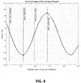
- step 10 of algorithm 5 is data acquisition and preparation of an energy waveform. The details of step 10 will now be described with reference to the subprocess shown in FIG. 2 and the waveforms shown in FIGS. 4-7 .
- a window of one voltage cycle is measured (step 12), and the time instant of maximum and minimum peaks of the voltage waveform (preferably after the first millisecond) is determined (step 14). It is advantageous to omit the first millisecond of the window from consideration because when this signal is filtered (as described below) ringing will occur in this time period.
- one and a half cycles of the grid voltage is captured to obtain the one voltage cycle.
- the "truncating mark" shown in FIG. 4 reduces the window of interest, since the data points before the truncating mark will be contaminated with noise from the digital filter.
- the arcing signatures are analyzed between the minimum and maximum peaks, as will be described in detail below.
- Step 16 a zero-crossing between the maximum and minimum peaks (which denotes an axis of symmetry) is determined.
- the zero-crossing marker denotes the axis of symmetry that divides the left-hand and right-hand sides. Steps 12-16 are illustrated by the waveform shown in FIG. 4 .
- a bandpass filter is applied to the entire voltage window (step 18), as shown in FIG. 5 . Accordingly, the captured grid voltage is digitally filtered.
- the markers for the minimum and maximum peak hold the analysis area of interest.
- the zero-crossing marker holds the position of the zero-crossing from the unfiltered voltage signal. Large peaks created by the digital filtering process are seen before the truncating mark and are not considered in the analysis described in detail below.
- the filtered window is truncated to between the instant between maximum and minimum peaks of the voltage waveform before the filtering, as shown in FIG. 6 . Accordingly, the digitally filtered signal is cropped so that only data between the minimum and maximum peak markers are analyzed.
- the voltage is squared at each sample point (step 22) to obtain V 2 energy values, thereby providing the resulting energy waveform shown in FIG. 7 . Accordingly, the cropped voltage signal shown in FIG. 6 is squared to generate the energy waveform of FIG. 7 . Both left-hand energy and right-and energy are shown in the calculated energy waveform of FIG. 7 .
- a lower energy threshold and an upper energy threshold are applied.
- the lower and upper energy thresholds are predetermined based on a pure grid voltage signal with no arcing.
- the upper energy threshold is outside the bounds of the plot shown in FIG. 7 .
- the left-hand energy values i.e., the energy values to the left of the zero-crossing
- the right-hand energy values i.e., the energy values to the right of the zero-crossing
- the left-hand energy values i.e., the energy values to the left of the zero-crossing
- the right-hand energy values i.e., the energy values to the right of the zero-crossing
- the left-hand energy values i.e., the energy values to the left of the zero-crossing
- the right-hand energy values i.e., the energy values to the right of the zero-crossing
- steps 30-38, 40-48, and 50-58 respectively associated with evaluation of left-hand energy summation (steps 30-38), right-hand energy summation (steps 40-48), and total energy summation (steps 50-58).
- the total energy summation refers to summation of both the left-hand energy value and the right-hand energy value.
- the left-hand energy summation value is obtained from step 10.
- a differential left-hand summation energy value is determined by subtracting the current left-hand summation energy value from the prior left-hand summation energy value (i.e., the left-hand summation energy value obtained during the prior iteration of step 10).
- the right-hand energy summation value is obtained from step 10.
- a differential right-hand summation energy value is determined by subtracting the current right-hand summation energy value from the prior right-hand summation energy value (i.e., the right-hand summation energy value obtained during the prior iteration of step 10).
- a total energy summation value is obtained by summing the left-hand summation value and the right-hand energy summation value.
- data acquisition step 10 is repeated in accordance with algorithm 5.
- a plurality of left-hand energy summation values (step 30), a plurality of right-hand energy summation values (step 40), and a plurality of total energy summation values (step 50) are obtained.
- FIG. 8 shows a plurality of left-hand energy summation values obtained at step 30 during the sampling period t .
- FIG. 9 shows a plurality of right-hand energy summation values obtained at step 40 during the sampling period t .
- the total energy summation values are the sum of the left-hand energy and right-hand energy summation values.
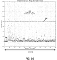
- FIG. 10 shows a plurality of differential left-hand summation energy values obtained at step 32 during the sampling period t .
- the plot shown in FIG. 10 emphasizes changes in the energy summation values with time.
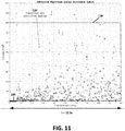
- a plurality of differential right-hand summation of energy values obtained at step 42 during the sampling period t are shown in FIG. 11 .
- steps 34, 44, and 54 it is determined whether, as a result of repeating step 10 according to algorithm 5, a sufficient number of energy summation values (i.e., left-hand energy summation values, right-hand energy summation values, and total energy summation values) have currently been obtained such that average energy summation values can be determined. If a sufficient number of energy summation values have been obtained, then average values are determined for the left-hand energy summation values, the right-hand summation values, and the total energy summation values (steps 36, 46, and 56). These average energy summation values are used to determine arc-tracking boundaries, as which will now be described in detail.
- a sufficient number of energy summation values i.e., left-hand energy summation values, right-hand energy summation values, and total energy summation values
- Arc-tracking boundaries for a stable arc detection region associated with the left-hand and right-hand energy summation values
- a transit arc detection region associated with differential left-hand and differential right-hand energy summation values
- Arc-tracking boundaries for a stable arc detection region and a transit arc detection region are determined based on the respective average energy summation values (steps 38, 48, and 58). It should be noted that the boundaries for stable arc detection region for both the left-hand and right-hand energy summation values are the same.
- the upper and lower boundaries are calculated each time there are a sufficient number of new energy summation values to take another average.
- FIGS. 8 and 9 show the stable arc detection region 102 defined by lower boundary 104 and upper boundary 106.
- the boundaries in the plot have reached their lower and upper limits which are constants determined in advance based on energy values due to sudden surges (i.e., switching loads) and normal operations (a baseline energy in the system) characterized specifically to energy on the left-hand side of the zero-crossing.
- the upper and lower boundaries are calculated every time there are a sufficient number of new energy summation values to take another average.
- FIG. 10 shows transient arc detection region 122, defined by lower boundary 124 and upper boundary 126, for the differential left-hand energy summation values.
- the boundaries in the plot have reached their lower and upper limits which are constants determined in advance based on energy values due to sudden surges (i.e., switching loads) and normal operations (a baseline energy in the system) characterized specifically to energy on the left-hand side of the zero-crossing.
- FIG. 11 shows transient arc detection region 132, defined by lower boundary 134 and upper boundary 136, for the differential right-hand energy summation values.
- predetermined minimum and maximum limit values may be established for the upper and lower boundaries defining the transient arc detection region.
- the calculated value for the lower boundary are less than the minimum limit value. Accordingly, lower boundaries 124 and 134 are set to the minimum limit value.
- the calculated value for the upper boundary are more than the maximum limit value. Accordingly, upper boundaries 126 and 136 are set to the maximum limit value.
- step 62 if both the differential left-hand energy summation value ( FIG. 10 ) and corresponding differential right-hand energy summation value ( FIG. 11 ) simultaneously remain inside their respective transient arc detection boundaries, then it is determined that a potential arcing signature has been detected and a potential arc flag is set (step 70).
- step 64 if both the left-hand energy summation value ( FIG. 8 ) and right-hand energy summation value ( FIG. 9 ) are simultaneously within the stable arc detection boundary, then a potential arcing signature has been detected and a potential arc flag is set (step 70).
- step 72 it is determined whether a predetermined number of consecutive potential arc flags have been set. If the predetermined number of consecutive potential arc flags have been set, then an arc fault is detected (step 74).
- a flag is set to keep track of all potential arcs.
- the downward pointing triangle is indicative of stable arc activity (step 64), while the upward pointing triangle is indicative of transient arc activity (step 62).
- the predetermined number of consecutive potential arc flags for detection of an arc fault is set for five (5) flags. Accordingly, when five (5) consecutive potential arcing signatures are detected, algorithm 5 determines that an arc fault has occurred (step 74). It should be appreciated that the predetermined number of consecutive flags that need to be set to detect an arc fault can set to other values in accordance with the present invention.
- algorithm 5 is repeated by returning to step 10 to acquire another set of energy summation values.
- an arc flag detection signal may be activated.
- a visual warning or other indicator may be activated in response to activation of this arc flag detection signal.
- an arc was generated at 800ms (on the x-axis in the graph it is tick 32).
- An arc fault was determined by algorithm 5 at 900ms (on the x-axis in the graph it is tick 36). Accordingly, the time required for an arc fault detection was 100ms for a system with 120Vrms 60Hz AC signal with an approximate load of 10.2A.
Landscapes
- Physics & Mathematics (AREA)
- General Physics & Mathematics (AREA)
- Testing Of Short-Circuits, Discontinuities, Leakage, Or Incorrect Line Connections (AREA)
- Locating Faults (AREA)
Abstract
Description
- The present invention relates generally to the detection of electrical arc faults, and more particularly to a method of AC arc fault detection that uses multidimensional energy points.
- This invention relates to identification of electrical arc faults and, more particularly, to a method for identifying the occurrence of AC arc events.
- An arc fault is a high power discharge of electricity between two or more conductors. This discharge translates into heat, which can break down the wire insulation and possibly trigger an electrical fire. Common causes of arc faults include faulty connections due to corrosion, and degradation of electrical wiring, equipment, and related interconnections due to temperature, humidity, vibration, or other environmental conditions. In some cases degradation is simply due to aging of components over a period of time.
- In view of the serious safety hazards associated with an arc fault, it is important to have the ability to quickly, reliably, and accurately detect the presence of an arc fault condition.
- Prior art methods for detecting AC arc faults have relied upon an analysis of disturbances in the "current" signal. In contrast, the present invention provides an improved method of AC arc fault detection that relies upon an analysis of the "voltage" signal to detect an arc fault.
- In accordance with the present invention, there is provided a method for detecting arc faults in an AC circuit, comprising: (a) measuring an AC voltage signal to obtain one cycle of the AC voltage signal; (b) obtaining a left-hand energy summation value and a right-hand energy summation value from the measured AC voltage signal, wherein the left-hand energy summation value is determined by summing left-hand energy values left of a zero-crossing and the right-hand energy summation value is determined by summing right-hand energy values right of the zero-crossing; (c) obtaining a differential left-hand energy summation value and a differential right-hand energy summation value, wherein the differential left-hand energy summation value and differential right-hand energy summation value respectively indicate changes in the left-hand energy summation value and the right-hand energy summation value; (d) obtaining a total energy summation value, wherein the total energy summation value is a sum of the left-hand energy summation value and the right-hand energy summation value; (e) determining whether both the differential left-hand energy summation value and the differential right-hand energy summation value are simultaneously inside their respective transient arc boundaries, wherein if both the differential left-hand energy summation value and the differential right-hand energy summation value are simultaneously inside their respective transient arc boundaries, then setting a potential arc flag; (f) determining whether both the left-hand energy summation value and the right-hand energy summation value are simultaneously inside a stable arc boundary, wherein if both the left-hand energy summation value and the right-hand energy summation value are simultaneously inside the stable arc boundary, then setting a potential arc flag; (g) detecting an arc fault if a predetermined number of consecutive potential arc flags are set; and (h) repeating steps (a) through (g) a plurality of times to monitor for arc faults.
- An advantage of the present invention is the provision of an AC arc fault detection method that relies upon an analysis of a voltage signal to detect an arc fault.
- Another advantage of the present invention is the provision of an AC arc fault detection method that is fast, reliable, and accurate.
- A still further advantage of the present invention is the provision of an AC arc fault detection method that reduces the time need to detect an AC arc fault.
- These and other advantages will become apparent from the following description of illustrated embodiments taken together with the accompanying drawings and the appended claims.
- The invention may take physical form in certain parts and arrangement of parts, an embodiment of which will be described in detail in the specification and illustrated in the accompanying drawings which form a part hereof, and wherein:
-
FIG. 1 is a flow chart of an arc fault detection algorithm according to an embodiment of the present invention; -
FIG. 2 is a flow chart of a subprocess of the arc fault detection algorithm shown inFIG. 1 ; -
FIG. 3 illustrates an example circuit where an arc fault is detected using the arc fault detection algorithm ofFIG. 1 ; -
FIG. 4 shows a captured grid voltage signal with arcing present; -
FIG. 5 shows the voltage signal ofFIG. 4 after digital filtering; -
FIG. 6 shows the digitally filtered signal ofFIG. 5 after cropping; -
FIG. 7 shows an energy waveform obtained by squaring the cropped voltage signal ofFIG. 6 ; -
FIG. 8 shows a plot of left-hand energy summation values; -
FIG. 9 shows a plot of right-hand energy summation values; -
FIG. 10 shows a plot of differential left-hand energy summation values; -
FIG. 11 shows a plot of differential right-hand energy summation values; -
FIG. 12 shows a plot of flags indicative of potential stable and transient arc activity; and -
FIG. 13 shows an output of a fault detection signal indicative of the presence/absence of an arc fault according to an embodiment of the present invention. - Referring now to the drawings wherein the showings are for the purposes of illustrating an embodiment of the invention only and not for the purposes of limiting same,
FIG. 1 is a flow chart of an arcfault detection algorithm 5, according to an embodiment of the present invention;FIG. 2 is a flow chart of a subprocess of arcfault detection algorithm 5, andFIG. 3 illustrates anexample circuit 2 where an arc fault is detected using arcfault detection algorithm 5.Circuit 2 is comprised of anAC power supply 80, avoltage divider 82, anair gap 84, and aload 86.Computer 90 is programmed to operate in accordance with arcfault detection algorithm 5 described in detail below. Voltage data is acquired bycomputer 90 using a data acquisition device 88 (e.g., National Instrument's Multifunction DAQ for USB - model no. NI USB-6221). - Referring now to
FIG. 1 ,step 10 ofalgorithm 5 is data acquisition and preparation of an energy waveform. The details ofstep 10 will now be described with reference to the subprocess shown inFIG. 2 and the waveforms shown inFIGS. 4-7 . - A window of one voltage cycle is measured (step 12), and the time instant of maximum and minimum peaks of the voltage waveform (preferably after the first millisecond) is determined (step 14). It is advantageous to omit the first millisecond of the window from consideration because when this signal is filtered (as described below) ringing will occur in this time period.
- In the illustrated embodiment, one and a half cycles of the grid voltage is captured to obtain the one voltage cycle. The "truncating mark" shown in
FIG. 4 reduces the window of interest, since the data points before the truncating mark will be contaminated with noise from the digital filter. The arcing signatures are analyzed between the minimum and maximum peaks, as will be described in detail below. - At
step 16, a zero-crossing between the maximum and minimum peaks (which denotes an axis of symmetry) is determined. The zero-crossing marker denotes the axis of symmetry that divides the left-hand and right-hand sides. Steps 12-16 are illustrated by the waveform shown inFIG. 4 . - Next, a bandpass filter is applied to the entire voltage window (step 18), as shown in
FIG. 5 . Accordingly, the captured grid voltage is digitally filtered. The markers for the minimum and maximum peak hold the analysis area of interest. The zero-crossing marker holds the position of the zero-crossing from the unfiltered voltage signal. Large peaks created by the digital filtering process are seen before the truncating mark and are not considered in the analysis described in detail below. - At
step 18, the filtered window is truncated to between the instant between maximum and minimum peaks of the voltage waveform before the filtering, as shown inFIG. 6 . Accordingly, the digitally filtered signal is cropped so that only data between the minimum and maximum peak markers are analyzed. - Next, the voltage is squared at each sample point (step 22) to obtain V2 energy values, thereby providing the resulting energy waveform shown in
FIG. 7 . Accordingly, the cropped voltage signal shown inFIG. 6 is squared to generate the energy waveform ofFIG. 7 . Both left-hand energy and right-and energy are shown in the calculated energy waveform ofFIG. 7 . - At
step 24, a lower energy threshold and an upper energy threshold are applied. The lower and upper energy thresholds are predetermined based on a pure grid voltage signal with no arcing. In the illustrated example, the upper energy threshold is outside the bounds of the plot shown inFIG. 7 . - At
step 26, the left-hand energy values (i.e., the energy values to the left of the zero-crossing) and the right-hand energy values (i.e., the energy values to the right of the zero-crossing), between the lower and upper thresholds, are respectively summed to obtain two (2) energy points (i.e., a left-hand energy summation value and a right-hand energy summation value). Data acquisition andpreparation step 10 shown inFIG. 2 is repeated as a subprocess to obtain a plurality of sets of energy points foralgorithm 5, as will be described below. For example, data may be acquired during a sampling period t. In the embodiment illustrated herein, the sampling period t is 12.5 seconds. However, it is contemplated that the sampling period may be a continuous period of time to thereby continuously monitor a circuit for detection of an AC arc fault. - Returning now to
FIG. 1 , there is shown three (3) different processes (steps 30-38, 40-48, and 50-58) respectively associated with evaluation of left-hand energy summation (steps 30-38), right-hand energy summation (steps 40-48), and total energy summation (steps 50-58). The total energy summation refers to summation of both the left-hand energy value and the right-hand energy value. - With reference to step 30, the left-hand energy summation value is obtained from
step 10. Atstep 32, a differential left-hand summation energy value is determined by subtracting the current left-hand summation energy value from the prior left-hand summation energy value (i.e., the left-hand summation energy value obtained during the prior iteration of step 10). Similarly, atstep 40, the right-hand energy summation value is obtained fromstep 10. Atstep 42, a differential right-hand summation energy value is determined by subtracting the current right-hand summation energy value from the prior right-hand summation energy value (i.e., the right-hand summation energy value obtained during the prior iteration of step 10). Atstep 50, a total energy summation value is obtained by summing the left-hand summation value and the right-hand energy summation value. - As will be discussed in further detail below,
data acquisition step 10 is repeated in accordance withalgorithm 5. Thus, a plurality of left-hand energy summation values (step 30), a plurality of right-hand energy summation values (step 40), and a plurality of total energy summation values (step 50) are obtained.FIG. 8 shows a plurality of left-hand energy summation values obtained atstep 30 during the sampling period t. Likewise,FIG. 9 shows a plurality of right-hand energy summation values obtained atstep 40 during the sampling period t. The total energy summation values are the sum of the left-hand energy and right-hand energy summation values.FIG. 10 shows a plurality of differential left-hand summation energy values obtained atstep 32 during the sampling period t. The plot shown inFIG. 10 emphasizes changes in the energy summation values with time. Likewise, a plurality of differential right-hand summation of energy values obtained atstep 42 during the sampling period t are shown inFIG. 11 . - Referring now to
steps step 10 according toalgorithm 5, a sufficient number of energy summation values (i.e., left-hand energy summation values, right-hand energy summation values, and total energy summation values) have currently been obtained such that average energy summation values can be determined.. If a sufficient number of energy summation values have been obtained, then average values are determined for the left-hand energy summation values, the right-hand summation values, and the total energy summation values (steps - Arc-tracking boundaries for a stable arc detection region (associated with the left-hand and right-hand energy summation values) and a transit arc detection region (associated with differential left-hand and differential right-hand energy summation values) are determined based on the respective average energy summation values (
steps - The calculations for determining (lower and upper) boundaries for establishing the stable arc detection region will now be described in detail. In accordance with an embodiment of the present invention, the stable arc detection region boundaries are calculated according to the following expression:

where: - SAarc is a value indicative of the upper and lower boundaries of the stable arc detection region;
- v2 avg is the arithmetic average of a group of consecutive left-hand and right-hand energy summation values; and
- XSA & YSA are constant scaling and offset values, respectively, determined empirically in advance.
- In accordance with an embodiment of the present invention, the upper and lower boundaries are calculated each time there are a sufficient number of new energy summation values to take another average.
-
FIGS. 8 and9 show the stablearc detection region 102 defined bylower boundary 104 andupper boundary 106. The boundaries in the plot have reached their lower and upper limits which are constants determined in advance based on energy values due to sudden surges (i.e., switching loads) and normal operations (a baseline energy in the system) characterized specifically to energy on the left-hand side of the zero-crossing. - The determination of boundaries for establishing the transient arc detection region for the differential left-hand energy summation values will now be described in detail. It should be noted that the determination of the boundaries for establishing the transient arc detection region for the differential right-hand energy summation values is substantially the same, however, values for differential right-hand energy summation values are substituted for differential left-hand energy summation values.
- In accordance with an embodiment of the present invention, the transient arc detection region boundaries for the differential left-hand energy summation values are calculated according to the following expression:

where: - TALarc is a value indicative of the upper and lower left-hand boundaries of the transient arc detection region;
- ΔV2 Lavg is the average of a group of consecutive differential left-hand energy summation values; and
- XLTA & YLTA are constant scaling and offset factors, respectively, determined empirically in advance.
- The upper and lower boundaries are calculated every time there are a sufficient number of new energy summation values to take another average.
-
FIG. 10 shows transientarc detection region 122, defined bylower boundary 124 andupper boundary 126, for the differential left-hand energy summation values. The boundaries in the plot have reached their lower and upper limits which are constants determined in advance based on energy values due to sudden surges (i.e., switching loads) and normal operations (a baseline energy in the system) characterized specifically to energy on the left-hand side of the zero-crossing. -
FIG. 11 , shows transientarc detection region 132, defined bylower boundary 134 andupper boundary 136, for the differential right-hand energy summation values. - In accordance with an embodiment of the present invention, predetermined minimum and maximum limit values may be established for the upper and lower boundaries defining the transient arc detection region. In the illustrated embodiment shown in
FIGS. 10 and11 , the calculated value for the lower boundary are less than the minimum limit value. Accordingly,lower boundaries upper boundaries - At
step 62, if both the differential left-hand energy summation value (FIG. 10 ) and corresponding differential right-hand energy summation value (FIG. 11 ) simultaneously remain inside their respective transient arc detection boundaries, then it is determined that a potential arcing signature has been detected and a potential arc flag is set (step 70). Similarly, atstep 64, if both the left-hand energy summation value (FIG. 8 ) and right-hand energy summation value (FIG. 9 ) are simultaneously within the stable arc detection boundary, then a potential arcing signature has been detected and a potential arc flag is set (step 70). Atstep 72, it is determined whether a predetermined number of consecutive potential arc flags have been set. If the predetermined number of consecutive potential arc flags have been set, then an arc fault is detected (step 74). - Referring now to
FIG. 12 , when a potential arcing signature is detected, a flag is set to keep track of all potential arcs. The downward pointing triangle is indicative of stable arc activity (step 64), while the upward pointing triangle is indicative of transient arc activity (step 62). - In the illustrated example embodiment of the present invention, the predetermined number of consecutive potential arc flags for detection of an arc fault is set for five (5) flags. Accordingly, when five (5) consecutive potential arcing signatures are detected,
algorithm 5 determines that an arc fault has occurred (step 74). It should be appreciated that the predetermined number of consecutive flags that need to be set to detect an arc fault can set to other values in accordance with the present invention. - If multiple consecutive flags have not been detected at
step 72, thenalgorithm 5 is repeated by returning to step 10 to acquire another set of energy summation values. - In response to detection of an arc fault at
step 74, an arc flag detection signal may be activated. A visual warning or other indicator may be activated in response to activation of this arc flag detection signal. - In the given example, an arc was generated at 800ms (on the x-axis in the graph it is tick 32). An arc fault was determined by
algorithm 5 at 900ms (on the x-axis in the graph it is tick 36). Accordingly, the time required for an arc fault detection was 100ms for a system with 120Vrms 60Hz AC signal with an approximate load of 10.2A. - The foregoing describes specific embodiments of the present invention. It should be appreciated that these embodiments are described for purposes of illustration only, and that numerous alterations and modifications may be practiced by those skilled in the art without departing from the spirit and scope of the invention. It is intended that all such modifications and alterations be included insofar as they come within the scope of the invention as claimed or the equivalents thereof.
Claims (7)
- A method for detecting arc faults in an AC circuit, comprising:(a) measuring an AC voltage signal (10) to obtain one cycle of the AC voltage signal;(b) obtaining a left-hand energy summation value (30) and a right-hand energy summation value (40) from the measured AC voltage signal, wherein the left-hand energy summation value is determined by summing left-hand energy values left of a zero-crossing and the right-hand energy summation value is determined by summing right-hand energy values right of the zero-crossing;(c) obtaining a differential left-hand energy summation value (32) and a differential right-hand energy summation value (42), wherein the differential left-hand energy summation value and differential right-hand energy summation value respectively indicate changes in the left-hand energy summation value and the right-hand energy summation value;(d) obtaining a total energy summation value (50), wherein the total energy summation value is a sum of the left-hand energy summation value and the right-hand energy summation value;(e) determining whether both the differential left-hand energy summation value and the differential right-hand energy summation value are simultaneously inside their respective transient arc boundaries, wherein if both the differential left-hand energy summation value and the differential right-hand energy summation value are simultaneously inside their respective transient arc boundaries, then setting a potential arc flag;(f) determining whether both the left-hand energy summation value and the right-hand energy summation value are simultaneously inside a stable arc boundary, wherein if both the left-hand energy summation value and the right-hand energy summation value are simultaneously inside the stable arc boundary, then setting a potential arc flag (70);(g) detecting an arc fault (74) if a predetermined number of consecutive potential arc flags are set; and(h) repeating steps (a) through (g) a plurality of times to monitor for arc faults.
- The method according to claim 1, wherein the step of obtaining the plurality of left-hand energy summation values and the plurality of right-hand energy summation values includes:determining maximum and minimum peaks (14) in the one cycle of the AC voltage signal;determining the zero-crossing (16) between the maximum and minimum peaks of the one cycle of the AC voltage signal;applying a band pass filter (18) to the one cycle of the AC voltage signal;truncating (20) the one cycle of the AC voltage signal to a window between the maximum and the minimum peaks;squaring (22) voltage values of the one cycle of the AC voltage signal to obtain squared voltage values indicative of energy values;applying (24) minimum and maximum energy thresholds to the energy values; andsumming (26) the energy values to the left of the zero-crossing within the minimum and maximum energy thresholds to determine the left-hand energy summation value and summing the energy values to the right of the zero-crossing within the minimum and maximum energy thresholds to determine the right-hand energy summation value.
- The method according to claim 1 or 2, wherein the stable arc boundary is determined using an arithmetic average of a group of consecutive left-hand and right-hand energy summation values.
- The method according to any one of the preceding claims, wherein the transient arc detection boundary for the differential left-hand energy summation value is determined using an average of a group of consecutive differential left-hand energy summation values.
- The method according to any one of the preceding claims, wherein the transient arc detection boundary for the differential right-hand energy summation value is determined using an average of a group of consecutive differential right-hand energy summation values.
- The method according to any one of the preceding claims, wherein the predetermined number of consecutive potential arc flags is at least 5.
- The method according to any one of the preceding claims, wherein said transient arc boundaries and said stable arc boundary are re-calculated periodically.
Applications Claiming Priority (1)
| Application Number | Priority Date | Filing Date | Title |
|---|---|---|---|
| US15/642,409 US10509067B2 (en) | 2017-07-06 | 2017-07-06 | Method for AC arc fault detection using multidimensional energy points |
Publications (2)
| Publication Number | Publication Date |
|---|---|
| EP3442087A1 true EP3442087A1 (en) | 2019-02-13 |
| EP3442087B1 EP3442087B1 (en) | 2022-08-17 |
Family
ID=62791679
Family Applications (1)
| Application Number | Title | Priority Date | Filing Date |
|---|---|---|---|
| EP18180028.5A Active EP3442087B1 (en) | 2017-07-06 | 2018-06-27 | Method for ac arc fault detection using multidimensional energy points |
Country Status (4)
| Country | Link |
|---|---|
| US (1) | US10509067B2 (en) |
| EP (1) | EP3442087B1 (en) |
| CN (1) | CN109212387B (en) |
| ES (1) | ES2927486T3 (en) |
Cited By (1)
| Publication number | Priority date | Publication date | Assignee | Title |
|---|---|---|---|---|
| WO2026074251A1 (en) | 2024-10-03 | 2026-04-09 | Safran Electrical & Power | Method and device for protection against electric arcs |
Families Citing this family (3)
| Publication number | Priority date | Publication date | Assignee | Title |
|---|---|---|---|---|
| US10641806B2 (en) * | 2018-03-20 | 2020-05-05 | Whisker Labs, Inc. | Detection of electric discharges that precede fires in electrical wiring |
| CN111025102B (en) * | 2019-12-13 | 2022-04-19 | 湖南长高思瑞自动化有限公司 | Low-voltage arc fault detection method and device based on voltage waveform analysis |
| CN113970678A (en) * | 2021-10-18 | 2022-01-25 | 上海华建电力设备股份有限公司 | Series arc fault detection method based on terminal power supply voltage waveform |
Citations (3)
| Publication number | Priority date | Publication date | Assignee | Title |
|---|---|---|---|---|
| US5485093A (en) * | 1993-10-15 | 1996-01-16 | The Texas A & M University System | Randomness fault detection system |
| WO2011011711A2 (en) * | 2009-07-23 | 2011-01-27 | Enphase Energy, Inc. | Method and apparatus for detection and control of dc arc faults |
| US20150357972A1 (en) * | 2013-02-22 | 2015-12-10 | Commissariat A L'energie Atomique Et Aux Energies Alternatives | Method and device for detecting electrical arcing in a photovoltaic installation |
Family Cites Families (31)
| Publication number | Priority date | Publication date | Assignee | Title |
|---|---|---|---|---|
| US5729145A (en) | 1992-07-30 | 1998-03-17 | Siemens Energy & Automation, Inc. | Method and apparatus for detecting arcing in AC power systems by monitoring high frequency noise |
| CN1179213C (en) * | 1997-08-14 | 2004-12-08 | 亨德里机械工厂 | Arc Monitoring System |
| US6625550B1 (en) | 1998-02-19 | 2003-09-23 | Square D Company | Arc fault detection for aircraft |
| US6362628B2 (en) * | 1998-12-21 | 2002-03-26 | Pass & Seymour, Inc. | Arc fault circuit detector device detecting pulse width modulation of arc noise |
| CA2414273C (en) | 2000-06-26 | 2012-04-10 | Premier Aviation, Inc. | Method and apparatus for detecting electrical faults and isolating power source from the electrical faults |
| US20050254187A1 (en) | 2004-05-11 | 2005-11-17 | Defond Components Limited | Arc fault circuit interrupter |
| FR2876187B1 (en) * | 2004-10-01 | 2006-12-15 | Airbus France Sas | METHOD AND DEVICE FOR DETECTING AN ELECTRIC ARC PHENOMENON ON AT LEAST ONE ELECTRICAL CABLE |
| DE102004056436B4 (en) | 2004-11-19 | 2019-04-04 | Jenoptik Advanced Systems Gmbh | Method and device for detecting residual current arcs in electrical circuits |
| US7391218B2 (en) | 2005-03-11 | 2008-06-24 | Honeywell International Inc. | Method and apparatus for generalized arc fault detection |
| US7460346B2 (en) | 2005-03-24 | 2008-12-02 | Honeywell International Inc. | Arc fault detection and confirmation using voltage and current analysis |
| US7796366B2 (en) | 2005-12-09 | 2010-09-14 | Hamilton Sundstrand Corporation | AC arc fault detection and protection |
| US7400481B2 (en) | 2005-12-29 | 2008-07-15 | Sensata Technologies, Inc. | Low cost arc fault detection technique |
| US7499250B2 (en) * | 2006-04-19 | 2009-03-03 | Siemens Energy & Automation, Inc. | Systems, devices, and methods for temperature compensation in arc fault detection systems |
| US7750645B2 (en) | 2007-08-15 | 2010-07-06 | Applied Materials, Inc. | Method of wafer level transient sensing, threshold comparison and arc flag generation/deactivation |
| JP5369490B2 (en) | 2008-05-13 | 2013-12-18 | シンフォニアテクノロジー株式会社 | Arc detection device and aircraft equipped with the same |
| JP5419579B2 (en) * | 2009-05-28 | 2014-02-19 | 京セラ株式会社 | Arc detection means and control means and communication means using the same |
| KR20120032925A (en) | 2010-09-29 | 2012-04-06 | 삼성전자주식회사 | Electric apparatus, electric apparatus system and method for detecting arc fault thereof |
| US20130015875A1 (en) | 2011-07-13 | 2013-01-17 | United Solar Ovonic Llc | Failure detection system for photovoltaic array |
| US9329220B2 (en) | 2012-08-27 | 2016-05-03 | The Texas A&M University System | Method and system for detecting arc faults and flashes using wavelets |
| DE102012215310B4 (en) * | 2012-08-29 | 2020-09-03 | Siemens Aktiengesellschaft | Circuit arrangement for an electrical protective device |
| CN105445611B (en) * | 2014-05-30 | 2019-11-08 | 西门子公司 | Detection method and detection device of arc fault |
| CN105223427B (en) * | 2014-06-17 | 2019-05-17 | 西门子公司 | The detection method and detection device of fault electric arc |
| CN104360205A (en) | 2014-12-01 | 2015-02-18 | 河北工业大学 | Cascaded arc fault detection method and special device for cascaded arc fault detection method |
| US9797941B2 (en) | 2014-12-29 | 2017-10-24 | Eaton Corporation | Arc fault detection system and method and circuit interrupter employing same |
| CN104764963B (en) | 2015-04-20 | 2018-03-13 | 河北工业大学 | Alternating current arc fault detection method |
| US20160370420A1 (en) | 2015-06-16 | 2016-12-22 | Clinton Instrument Company | Apparatus and method for spark fault detection and typing |
| CN105067966B (en) * | 2015-07-08 | 2017-10-10 | 上海交通大学 | The low-voltage alternating-current fault arc detection method of feature based modal components energy spectrometer |
| CN106771798A (en) * | 2015-11-25 | 2017-05-31 | 山东建筑大学 | A kind of fault arc detection method based on the equal difference of wavelet coefficient |
| FR3046232B1 (en) * | 2015-12-28 | 2018-02-16 | Commissariat A L'energie Atomique Et Aux Energies Alternatives | METHOD FOR DETECTING AN ELECTRIC ARC BY ANALYSIS OF ITS ACOUSTIC SIGNATURE |
| CN107300662B (en) * | 2017-08-14 | 2020-07-28 | 北京腾控科技有限公司 | Arc alarm without external power supply |
| CN107994866B (en) * | 2017-12-07 | 2019-10-08 | 科华恒盛股份有限公司 | Method, apparatus, equipment and the storage medium of direct current arc fault detection |
-
2017
- 2017-07-06 US US15/642,409 patent/US10509067B2/en active Active
-
2018
- 2018-06-25 CN CN201810657276.5A patent/CN109212387B/en active Active
- 2018-06-27 ES ES18180028T patent/ES2927486T3/en active Active
- 2018-06-27 EP EP18180028.5A patent/EP3442087B1/en active Active
Patent Citations (3)
| Publication number | Priority date | Publication date | Assignee | Title |
|---|---|---|---|---|
| US5485093A (en) * | 1993-10-15 | 1996-01-16 | The Texas A & M University System | Randomness fault detection system |
| WO2011011711A2 (en) * | 2009-07-23 | 2011-01-27 | Enphase Energy, Inc. | Method and apparatus for detection and control of dc arc faults |
| US20150357972A1 (en) * | 2013-02-22 | 2015-12-10 | Commissariat A L'energie Atomique Et Aux Energies Alternatives | Method and device for detecting electrical arcing in a photovoltaic installation |
Cited By (2)
| Publication number | Priority date | Publication date | Assignee | Title |
|---|---|---|---|---|
| WO2026074251A1 (en) | 2024-10-03 | 2026-04-09 | Safran Electrical & Power | Method and device for protection against electric arcs |
| FR3167259A1 (en) | 2024-10-03 | 2026-04-10 | Safran Electrical & Power | METHOD AND DEVICE FOR PROTECTION AGAINST ELECTRIC ARCS |
Also Published As
| Publication number | Publication date |
|---|---|
| ES2927486T3 (en) | 2022-11-07 |
| EP3442087B1 (en) | 2022-08-17 |
| US10509067B2 (en) | 2019-12-17 |
| US20190011489A1 (en) | 2019-01-10 |
| CN109212387B (en) | 2020-12-29 |
| CN109212387A (en) | 2019-01-15 |
Similar Documents
| Publication | Publication Date | Title |
|---|---|---|
| EP3442087B1 (en) | Method for ac arc fault detection using multidimensional energy points | |
| US10620256B2 (en) | Direct current meter employing waveform separator for detecting leakage current | |
| US7865321B2 (en) | Arcing event detection | |
| EP3695476B1 (en) | Arc detection based on variance of current flow | |
| US20060109009A1 (en) | Method and device for the detection of fault current arcing in electric circuits | |
| US7366622B1 (en) | Arc fault identification using model reference estimation | |
| EP2999970B1 (en) | Sub-harmonic arc fault detection method | |
| EP2999969B1 (en) | Arc fault detection system and method | |
| KR20120036804A (en) | Method and system for transient and intermittent earth fault detection and direction determination in a three phase median voltage electric power distribution system | |
| US20200332948A1 (en) | Systems and methods for detecting and identifying arcing based on numerical analysis | |
| EP2200139A2 (en) | Arc detection using detailed and approximate coefficients from discrete wavelet transforms | |
| US10804703B2 (en) | Waveform separator apparatus and method for detecting leakage current in high voltage direct current power systems | |
| US10243343B2 (en) | Systems and methods for detecting and identifying arcing based on numerical analysis | |
| WO2014086381A1 (en) | Method for isolation monitoring | |
| EP2174149B1 (en) | A method and an apparatus for monitoring an activity of partial electrical discharges in an electrical apparatus powered with direct voltage | |
| CN107850640A (en) | DC meter and application method | |
| Abdullah et al. | Adaptive detection of dc arc faults based on hurst exponents and current envelope | |
| Ananthan et al. | Signatures of series arc faults to aid arc detection in low-voltage DC systems | |
| US10778142B2 (en) | Method and device for evaluating the energy produced by an electric arc in a photovoltaic installation | |
| JP7057718B2 (en) | High resistance ground fault detector for DC feeders | |
| KR101505591B1 (en) | Condition Monitoring Method and System for Power Equipments by on-line Power Spectrum Differential Measurement | |
| JP2006164787A (en) | Earth leakage breaker operation cause analyzer | |
| CN105116221B (en) | A kind of arrester voltage follow method of discrimination and device | |
| TWI231079B (en) | Insulation diagnostic device | |
| EP3548906B1 (en) | Waveform separator apparatus and method for detecting leakage current in high voltage direct current power systems |
Legal Events
| Date | Code | Title | Description |
|---|---|---|---|
| PUAI | Public reference made under article 153(3) epc to a published international application that has entered the european phase |
Free format text: ORIGINAL CODE: 0009012 |
|
| STAA | Information on the status of an ep patent application or granted ep patent |
Free format text: STATUS: THE APPLICATION HAS BEEN PUBLISHED |
|
| AK | Designated contracting states |
Kind code of ref document: A1 Designated state(s): AL AT BE BG CH CY CZ DE DK EE ES FI FR GB GR HR HU IE IS IT LI LT LU LV MC MK MT NL NO PL PT RO RS SE SI SK SM TR |
|
| AX | Request for extension of the european patent |
Extension state: BA ME |
|
| STAA | Information on the status of an ep patent application or granted ep patent |
Free format text: STATUS: REQUEST FOR EXAMINATION WAS MADE |
|
| 17P | Request for examination filed |
Effective date: 20190725 |
|
| RBV | Designated contracting states (corrected) |
Designated state(s): AL AT BE BG CH CY CZ DE DK EE ES FI FR GB GR HR HU IE IS IT LI LT LU LV MC MK MT NL NO PL PT RO RS SE SI SK SM TR |
|
| RAP1 | Party data changed (applicant data changed or rights of an application transferred) |
Owner name: NORTHEASTERN UNIVERSITY Owner name: MERSEN USA EP CORP. |
|
| RIC1 | Information provided on ipc code assigned before grant |
Ipc: G01R 31/52 20200101ALI20210722BHEP Ipc: H02H 1/00 20060101AFI20210722BHEP |
|
| GRAP | Despatch of communication of intention to grant a patent |
Free format text: ORIGINAL CODE: EPIDOSNIGR1 |
|
| STAA | Information on the status of an ep patent application or granted ep patent |
Free format text: STATUS: GRANT OF PATENT IS INTENDED |
|
| INTG | Intention to grant announced |
Effective date: 20210928 |
|
| GRAJ | Information related to disapproval of communication of intention to grant by the applicant or resumption of examination proceedings by the epo deleted |
Free format text: ORIGINAL CODE: EPIDOSDIGR1 |
|
| STAA | Information on the status of an ep patent application or granted ep patent |
Free format text: STATUS: REQUEST FOR EXAMINATION WAS MADE |
|
| INTC | Intention to grant announced (deleted) | ||
| GRAP | Despatch of communication of intention to grant a patent |
Free format text: ORIGINAL CODE: EPIDOSNIGR1 |
|
| STAA | Information on the status of an ep patent application or granted ep patent |
Free format text: STATUS: GRANT OF PATENT IS INTENDED |
|
| INTG | Intention to grant announced |
Effective date: 20220310 |
|
| GRAS | Grant fee paid |
Free format text: ORIGINAL CODE: EPIDOSNIGR3 |
|
| GRAA | (expected) grant |
Free format text: ORIGINAL CODE: 0009210 |
|
| STAA | Information on the status of an ep patent application or granted ep patent |
Free format text: STATUS: THE PATENT HAS BEEN GRANTED |
|
| AK | Designated contracting states |
Kind code of ref document: B1 Designated state(s): AL AT BE BG CH CY CZ DE DK EE ES FI FR GB GR HR HU IE IS IT LI LT LU LV MC MK MT NL NO PL PT RO RS SE SI SK SM TR |
|
| REG | Reference to a national code |
Ref country code: CH Ref legal event code: EP |
|
| REG | Reference to a national code |
Ref country code: DE Ref legal event code: R096 Ref document number: 602018039319 Country of ref document: DE |
|
| REG | Reference to a national code |
Ref country code: IE Ref legal event code: FG4D |
|
| REG | Reference to a national code |
Ref country code: AT Ref legal event code: REF Ref document number: 1512794 Country of ref document: AT Kind code of ref document: T Effective date: 20220915 |
|
| REG | Reference to a national code |
Ref country code: ES Ref legal event code: FG2A Ref document number: 2927486 Country of ref document: ES Kind code of ref document: T3 Effective date: 20221107 |
|
| REG | Reference to a national code |
Ref country code: NL Ref legal event code: MP Effective date: 20220817 |
|
| REG | Reference to a national code |
Ref country code: LT Ref legal event code: MG9D |
|
| PG25 | Lapsed in a contracting state [announced via postgrant information from national office to epo] |
Ref country code: SE Free format text: LAPSE BECAUSE OF FAILURE TO SUBMIT A TRANSLATION OF THE DESCRIPTION OR TO PAY THE FEE WITHIN THE PRESCRIBED TIME-LIMIT Effective date: 20220817 Ref country code: RS Free format text: LAPSE BECAUSE OF FAILURE TO SUBMIT A TRANSLATION OF THE DESCRIPTION OR TO PAY THE FEE WITHIN THE PRESCRIBED TIME-LIMIT Effective date: 20220817 Ref country code: PT Free format text: LAPSE BECAUSE OF FAILURE TO SUBMIT A TRANSLATION OF THE DESCRIPTION OR TO PAY THE FEE WITHIN THE PRESCRIBED TIME-LIMIT Effective date: 20221219 Ref country code: NO Free format text: LAPSE BECAUSE OF FAILURE TO SUBMIT A TRANSLATION OF THE DESCRIPTION OR TO PAY THE FEE WITHIN THE PRESCRIBED TIME-LIMIT Effective date: 20221117 Ref country code: NL Free format text: LAPSE BECAUSE OF FAILURE TO SUBMIT A TRANSLATION OF THE DESCRIPTION OR TO PAY THE FEE WITHIN THE PRESCRIBED TIME-LIMIT Effective date: 20220817 Ref country code: LV Free format text: LAPSE BECAUSE OF FAILURE TO SUBMIT A TRANSLATION OF THE DESCRIPTION OR TO PAY THE FEE WITHIN THE PRESCRIBED TIME-LIMIT Effective date: 20220817 Ref country code: LT Free format text: LAPSE BECAUSE OF FAILURE TO SUBMIT A TRANSLATION OF THE DESCRIPTION OR TO PAY THE FEE WITHIN THE PRESCRIBED TIME-LIMIT Effective date: 20220817 Ref country code: FI Free format text: LAPSE BECAUSE OF FAILURE TO SUBMIT A TRANSLATION OF THE DESCRIPTION OR TO PAY THE FEE WITHIN THE PRESCRIBED TIME-LIMIT Effective date: 20220817 |
|
| REG | Reference to a national code |
Ref country code: AT Ref legal event code: MK05 Ref document number: 1512794 Country of ref document: AT Kind code of ref document: T Effective date: 20220817 |
|
| PG25 | Lapsed in a contracting state [announced via postgrant information from national office to epo] |
Ref country code: PL Free format text: LAPSE BECAUSE OF FAILURE TO SUBMIT A TRANSLATION OF THE DESCRIPTION OR TO PAY THE FEE WITHIN THE PRESCRIBED TIME-LIMIT Effective date: 20220817 Ref country code: IS Free format text: LAPSE BECAUSE OF FAILURE TO SUBMIT A TRANSLATION OF THE DESCRIPTION OR TO PAY THE FEE WITHIN THE PRESCRIBED TIME-LIMIT Effective date: 20221217 Ref country code: HR Free format text: LAPSE BECAUSE OF FAILURE TO SUBMIT A TRANSLATION OF THE DESCRIPTION OR TO PAY THE FEE WITHIN THE PRESCRIBED TIME-LIMIT Effective date: 20220817 Ref country code: GR Free format text: LAPSE BECAUSE OF FAILURE TO SUBMIT A TRANSLATION OF THE DESCRIPTION OR TO PAY THE FEE WITHIN THE PRESCRIBED TIME-LIMIT Effective date: 20221118 |
|
| PG25 | Lapsed in a contracting state [announced via postgrant information from national office to epo] |
Ref country code: SM Free format text: LAPSE BECAUSE OF FAILURE TO SUBMIT A TRANSLATION OF THE DESCRIPTION OR TO PAY THE FEE WITHIN THE PRESCRIBED TIME-LIMIT Effective date: 20220817 Ref country code: RO Free format text: LAPSE BECAUSE OF FAILURE TO SUBMIT A TRANSLATION OF THE DESCRIPTION OR TO PAY THE FEE WITHIN THE PRESCRIBED TIME-LIMIT Effective date: 20220817 Ref country code: DK Free format text: LAPSE BECAUSE OF FAILURE TO SUBMIT A TRANSLATION OF THE DESCRIPTION OR TO PAY THE FEE WITHIN THE PRESCRIBED TIME-LIMIT Effective date: 20220817 Ref country code: CZ Free format text: LAPSE BECAUSE OF FAILURE TO SUBMIT A TRANSLATION OF THE DESCRIPTION OR TO PAY THE FEE WITHIN THE PRESCRIBED TIME-LIMIT Effective date: 20220817 Ref country code: AT Free format text: LAPSE BECAUSE OF FAILURE TO SUBMIT A TRANSLATION OF THE DESCRIPTION OR TO PAY THE FEE WITHIN THE PRESCRIBED TIME-LIMIT Effective date: 20220817 |
|
| REG | Reference to a national code |
Ref country code: DE Ref legal event code: R097 Ref document number: 602018039319 Country of ref document: DE |
|
| PG25 | Lapsed in a contracting state [announced via postgrant information from national office to epo] |
Ref country code: SK Free format text: LAPSE BECAUSE OF FAILURE TO SUBMIT A TRANSLATION OF THE DESCRIPTION OR TO PAY THE FEE WITHIN THE PRESCRIBED TIME-LIMIT Effective date: 20220817 Ref country code: EE Free format text: LAPSE BECAUSE OF FAILURE TO SUBMIT A TRANSLATION OF THE DESCRIPTION OR TO PAY THE FEE WITHIN THE PRESCRIBED TIME-LIMIT Effective date: 20220817 |
|
| PLBE | No opposition filed within time limit |
Free format text: ORIGINAL CODE: 0009261 |
|
| STAA | Information on the status of an ep patent application or granted ep patent |
Free format text: STATUS: NO OPPOSITION FILED WITHIN TIME LIMIT |
|
| PG25 | Lapsed in a contracting state [announced via postgrant information from national office to epo] |
Ref country code: AL Free format text: LAPSE BECAUSE OF FAILURE TO SUBMIT A TRANSLATION OF THE DESCRIPTION OR TO PAY THE FEE WITHIN THE PRESCRIBED TIME-LIMIT Effective date: 20220817 |
|
| 26N | No opposition filed |
Effective date: 20230519 |
|
| PG25 | Lapsed in a contracting state [announced via postgrant information from national office to epo] |
Ref country code: SI Free format text: LAPSE BECAUSE OF FAILURE TO SUBMIT A TRANSLATION OF THE DESCRIPTION OR TO PAY THE FEE WITHIN THE PRESCRIBED TIME-LIMIT Effective date: 20220817 |
|
| PG25 | Lapsed in a contracting state [announced via postgrant information from national office to epo] |
Ref country code: MC Free format text: LAPSE BECAUSE OF FAILURE TO SUBMIT A TRANSLATION OF THE DESCRIPTION OR TO PAY THE FEE WITHIN THE PRESCRIBED TIME-LIMIT Effective date: 20220817 |
|
| PG25 | Lapsed in a contracting state [announced via postgrant information from national office to epo] |
Ref country code: MC Free format text: LAPSE BECAUSE OF FAILURE TO SUBMIT A TRANSLATION OF THE DESCRIPTION OR TO PAY THE FEE WITHIN THE PRESCRIBED TIME-LIMIT Effective date: 20220817 |
|
| REG | Reference to a national code |
Ref country code: CH Ref legal event code: PL |
|
| REG | Reference to a national code |
Ref country code: BE Ref legal event code: MM Effective date: 20230630 |
|
| GBPC | Gb: european patent ceased through non-payment of renewal fee |
Effective date: 20230627 |
|
| PG25 | Lapsed in a contracting state [announced via postgrant information from national office to epo] |
Ref country code: LU Free format text: LAPSE BECAUSE OF NON-PAYMENT OF DUE FEES Effective date: 20230627 |
|
| REG | Reference to a national code |
Ref country code: IE Ref legal event code: MM4A |
|
| PG25 | Lapsed in a contracting state [announced via postgrant information from national office to epo] |
Ref country code: LU Free format text: LAPSE BECAUSE OF NON-PAYMENT OF DUE FEES Effective date: 20230627 |
|
| PG25 | Lapsed in a contracting state [announced via postgrant information from national office to epo] |
Ref country code: IE Free format text: LAPSE BECAUSE OF NON-PAYMENT OF DUE FEES Effective date: 20230627 |
|
| PG25 | Lapsed in a contracting state [announced via postgrant information from national office to epo] |
Ref country code: IE Free format text: LAPSE BECAUSE OF NON-PAYMENT OF DUE FEES Effective date: 20230627 Ref country code: CH Free format text: LAPSE BECAUSE OF NON-PAYMENT OF DUE FEES Effective date: 20230630 Ref country code: GB Free format text: LAPSE BECAUSE OF NON-PAYMENT OF DUE FEES Effective date: 20230627 |
|
| PG25 | Lapsed in a contracting state [announced via postgrant information from national office to epo] |
Ref country code: IT Free format text: LAPSE BECAUSE OF FAILURE TO SUBMIT A TRANSLATION OF THE DESCRIPTION OR TO PAY THE FEE WITHIN THE PRESCRIBED TIME-LIMIT Effective date: 20220817 Ref country code: BE Free format text: LAPSE BECAUSE OF NON-PAYMENT OF DUE FEES Effective date: 20230630 |
|
| PG25 | Lapsed in a contracting state [announced via postgrant information from national office to epo] |
Ref country code: BG Free format text: LAPSE BECAUSE OF FAILURE TO SUBMIT A TRANSLATION OF THE DESCRIPTION OR TO PAY THE FEE WITHIN THE PRESCRIBED TIME-LIMIT Effective date: 20220817 |
|
| PG25 | Lapsed in a contracting state [announced via postgrant information from national office to epo] |
Ref country code: BG Free format text: LAPSE BECAUSE OF FAILURE TO SUBMIT A TRANSLATION OF THE DESCRIPTION OR TO PAY THE FEE WITHIN THE PRESCRIBED TIME-LIMIT Effective date: 20220817 |
|
| PGFP | Annual fee paid to national office [announced via postgrant information from national office to epo] |
Ref country code: DE Payment date: 20250520 Year of fee payment: 8 |
|
| PGFP | Annual fee paid to national office [announced via postgrant information from national office to epo] |
Ref country code: FR Payment date: 20250521 Year of fee payment: 8 |
|
| PG25 | Lapsed in a contracting state [announced via postgrant information from national office to epo] |
Ref country code: CY Free format text: LAPSE BECAUSE OF FAILURE TO SUBMIT A TRANSLATION OF THE DESCRIPTION OR TO PAY THE FEE WITHIN THE PRESCRIBED TIME-LIMIT; INVALID AB INITIO Effective date: 20180627 |
|
| PG25 | Lapsed in a contracting state [announced via postgrant information from national office to epo] |
Ref country code: HU Free format text: LAPSE BECAUSE OF FAILURE TO SUBMIT A TRANSLATION OF THE DESCRIPTION OR TO PAY THE FEE WITHIN THE PRESCRIBED TIME-LIMIT; INVALID AB INITIO Effective date: 20180627 |
|
| PGFP | Annual fee paid to national office [announced via postgrant information from national office to epo] |
Ref country code: ES Payment date: 20250701 Year of fee payment: 8 |
|
| PG25 | Lapsed in a contracting state [announced via postgrant information from national office to epo] |
Ref country code: TR Free format text: LAPSE BECAUSE OF FAILURE TO SUBMIT A TRANSLATION OF THE DESCRIPTION OR TO PAY THE FEE WITHIN THE PRESCRIBED TIME-LIMIT Effective date: 20220817 |