EP3441885A1 - Technologies for caching persistent two-level memory data - Google Patents
Technologies for caching persistent two-level memory data Download PDFInfo
- Publication number
- EP3441885A1 EP3441885A1 EP18182324.6A EP18182324A EP3441885A1 EP 3441885 A1 EP3441885 A1 EP 3441885A1 EP 18182324 A EP18182324 A EP 18182324A EP 3441885 A1 EP3441885 A1 EP 3441885A1
- Authority
- EP
- European Patent Office
- Prior art keywords
- persistent
- data
- volatile memory
- memory
- address space
- Prior art date
- Legal status (The legal status is an assumption and is not a legal conclusion. Google has not performed a legal analysis and makes no representation as to the accuracy of the status listed.)
- Granted
Links
Images


Classifications
-
- G—PHYSICS
- G06—COMPUTING OR CALCULATING; COUNTING
- G06F—ELECTRIC DIGITAL DATA PROCESSING
- G06F12/00—Accessing, addressing or allocating within memory systems or architectures
- G06F12/02—Addressing or allocation; Relocation
- G06F12/0223—User address space allocation, e.g. contiguous or non contiguous base addressing
- G06F12/023—Free address space management
- G06F12/0238—Memory management in non-volatile memory, e.g. resistive RAM or ferroelectric memory
-
- G—PHYSICS
- G06—COMPUTING OR CALCULATING; COUNTING
- G06F—ELECTRIC DIGITAL DATA PROCESSING
- G06F12/00—Accessing, addressing or allocating within memory systems or architectures
- G06F12/02—Addressing or allocation; Relocation
- G06F12/08—Addressing or allocation; Relocation in hierarchically structured memory systems, e.g. virtual memory systems
- G06F12/0802—Addressing of a memory level in which the access to the desired data or data block requires associative addressing means, e.g. caches
- G06F12/0866—Addressing of a memory level in which the access to the desired data or data block requires associative addressing means, e.g. caches for peripheral storage systems, e.g. disk cache
- G06F12/0868—Data transfer between cache memory and other subsystems, e.g. storage devices or host systems
-
- G—PHYSICS
- G06—COMPUTING OR CALCULATING; COUNTING
- G06F—ELECTRIC DIGITAL DATA PROCESSING
- G06F12/00—Accessing, addressing or allocating within memory systems or architectures
- G06F12/02—Addressing or allocation; Relocation
- G06F12/0223—User address space allocation, e.g. contiguous or non contiguous base addressing
- G06F12/0292—User address space allocation, e.g. contiguous or non contiguous base addressing using tables or multilevel address translation means
-
- G—PHYSICS
- G06—COMPUTING OR CALCULATING; COUNTING
- G06F—ELECTRIC DIGITAL DATA PROCESSING
- G06F12/00—Accessing, addressing or allocating within memory systems or architectures
- G06F12/02—Addressing or allocation; Relocation
- G06F12/08—Addressing or allocation; Relocation in hierarchically structured memory systems, e.g. virtual memory systems
- G06F12/0802—Addressing of a memory level in which the access to the desired data or data block requires associative addressing means, e.g. caches
- G06F12/0866—Addressing of a memory level in which the access to the desired data or data block requires associative addressing means, e.g. caches for peripheral storage systems, e.g. disk cache
- G06F12/0873—Mapping of cache memory to specific storage devices or parts thereof
-
- G—PHYSICS
- G06—COMPUTING OR CALCULATING; COUNTING
- G06F—ELECTRIC DIGITAL DATA PROCESSING
- G06F12/00—Accessing, addressing or allocating within memory systems or architectures
- G06F12/02—Addressing or allocation; Relocation
- G06F12/08—Addressing or allocation; Relocation in hierarchically structured memory systems, e.g. virtual memory systems
- G06F12/0802—Addressing of a memory level in which the access to the desired data or data block requires associative addressing means, e.g. caches
- G06F12/0888—Addressing of a memory level in which the access to the desired data or data block requires associative addressing means, e.g. caches using selective caching, e.g. bypass
-
- G—PHYSICS
- G06—COMPUTING OR CALCULATING; COUNTING
- G06F—ELECTRIC DIGITAL DATA PROCESSING
- G06F12/00—Accessing, addressing or allocating within memory systems or architectures
- G06F12/02—Addressing or allocation; Relocation
- G06F12/08—Addressing or allocation; Relocation in hierarchically structured memory systems, e.g. virtual memory systems
- G06F12/12—Replacement control
- G06F12/121—Replacement control using replacement algorithms
- G06F12/128—Replacement control using replacement algorithms adapted to multidimensional cache systems, e.g. set-associative, multicache, multiset or multilevel
-
- G—PHYSICS
- G06—COMPUTING OR CALCULATING; COUNTING
- G06F—ELECTRIC DIGITAL DATA PROCESSING
- G06F2212/00—Indexing scheme relating to accessing, addressing or allocation within memory systems or architectures
- G06F2212/10—Providing a specific technical effect
- G06F2212/1016—Performance improvement
- G06F2212/1024—Latency reduction
-
- G—PHYSICS
- G06—COMPUTING OR CALCULATING; COUNTING
- G06F—ELECTRIC DIGITAL DATA PROCESSING
- G06F2212/00—Indexing scheme relating to accessing, addressing or allocation within memory systems or architectures
- G06F2212/10—Providing a specific technical effect
- G06F2212/1032—Reliability improvement, data loss prevention, degraded operation etc
-
- G—PHYSICS
- G06—COMPUTING OR CALCULATING; COUNTING
- G06F—ELECTRIC DIGITAL DATA PROCESSING
- G06F2212/00—Indexing scheme relating to accessing, addressing or allocation within memory systems or architectures
- G06F2212/20—Employing a main memory using a specific memory technology
- G06F2212/205—Hybrid memory, e.g. using both volatile and non-volatile memory
-
- G—PHYSICS
- G06—COMPUTING OR CALCULATING; COUNTING
- G06F—ELECTRIC DIGITAL DATA PROCESSING
- G06F2212/00—Indexing scheme relating to accessing, addressing or allocation within memory systems or architectures
- G06F2212/72—Details relating to flash memory management
- G06F2212/7201—Logical to physical mapping or translation of blocks or pages
-
- G—PHYSICS
- G06—COMPUTING OR CALCULATING; COUNTING
- G06F—ELECTRIC DIGITAL DATA PROCESSING
- G06F2212/00—Indexing scheme relating to accessing, addressing or allocation within memory systems or architectures
- G06F2212/72—Details relating to flash memory management
- G06F2212/7203—Temporary buffering, e.g. using volatile buffer or dedicated buffer blocks
-
- G—PHYSICS
- G06—COMPUTING OR CALCULATING; COUNTING
- G06F—ELECTRIC DIGITAL DATA PROCESSING
- G06F3/00—Input arrangements for transferring data to be processed into a form capable of being handled by the computer; Output arrangements for transferring data from processing unit to output unit, e.g. interface arrangements
- G06F3/06—Digital input from, or digital output to, record carriers, e.g. RAID, emulated record carriers or networked record carriers
- G06F3/0601—Interfaces specially adapted for storage systems
- G06F3/0628—Interfaces specially adapted for storage systems making use of a particular technique
- G06F3/0646—Horizontal data movement in storage systems, i.e. moving data in between storage devices or systems
- G06F3/065—Replication mechanisms
Definitions
- memory used to store data in a computing system can be volatile to store volatile data or non-volatile to store persistent data.
- Volatile data cached in volatile memory are generally used as temporary data to support the functionality of a program during the run-time of the program.
- persistent data structures stored in non-volatile or persistent memory are available beyond the run-time of a program and may be reused across power cycles.
- references in the specification to "one embodiment,” “an embodiment,” “an illustrative embodiment,” etc., indicate that the embodiment described may include a particular feature, structure, or characteristic, but every embodiment may or may not necessarily include that particular feature, structure, or characteristic. Moreover, such phrases are not necessarily referring to the same embodiment. Further, when a particular feature, structure, or characteristic is described in connection with an embodiment, it is submitted that it is within the knowledge of one skilled in the art to effect such feature, structure, or characteristic in connection with other embodiments whether or not explicitly described.
- items included in a list in the form of "at least one A, B, and C” can mean (A); (B); (C); (A and B); (A and C); (B and C); or (A, B, and C).
- items listed in the form of "at least one of A, B, or C” can mean (A); (B); (C); (A and B); (A and C); (B and C); or (A, B, and C).
- the disclosed embodiments may be implemented, in some cases, in hardware, firmware, software, or any combination thereof.
- the disclosed embodiments may also be implemented as instructions carried by or stored on a transitory or non-transitory machine-readable (e.g., computer-readable) storage medium, which may be read and executed by one or more processors.
- a machine-readable storage medium may be embodied as any storage device, mechanism, or other physical structure for storing or transmitting information in a form readable by a machine (e.g., a volatile or non-volatile memory, a media disc, or other media device).
- an illustrative compute device 100 for caching persistent two-level memory (2LM) data includes a processor 102 and a memory 104, which is partitioned into two levels.
- One level referred to as the “near memory” includes volatile memory 130.
- the second level referred to as the “far memory” is embodied as a relatively slower memory (e.g., lower bandwidth and/or higher latency) as compared to the near memory (e.g., the volatile memory 130) and, in the illustrative embodiment, comprises non-volatile memory 140.
- the far memory may be volatile.
- the far memory is presented to an operating system executed by the processor 102 as main memory, while the near memory is transparent to the operating system.
- the near memory may act as a cache for the far memory, providing the processor 102 with faster access to data than would be possible if the data was only present in the far memory.
- the processor 102 is configured to set up caching of persistent data associated with an application 122 that is mapped to a persistent memory address space of the non-volatile memory 140. To do so, the processor 102 configures the persistent memory address space to operate in a persistent two-level memory (2LM) mode.
- 2LM persistent two-level memory
- the persistent 2LM mode provides direct access to the non-volatile memory 140 to store and/or load the persistent 2LM data and further allows the operating system to cache accesses to the persistent memory address space in the volatile memory 130 without implementing any changes to hardware components of the compute device 100.
- the processor 102 may be embodied as any type of processor capable of performing the functions described herein.
- the processor 102 may be embodied as a single or multi-core processor(s), digital signal processor, field programmable gate arrays (FPGA), microcontroller, or other processor or processing/controlling circuit.
- the memory 104 may be embodied as any type of volatile and/or non-volatile memory or data storage capable of performing the functions described herein.
- the processor 102 and the memory 104 may form a portion of a system-on-a-chip (SoC) and be incorporated, along with other components of the compute device 100, onto a single integrated circuit chip.
- SoC system-on-a-chip
- the memory 104 is communicatively coupled to the processor 102 via the I/O subsystem 106, which may be embodied as circuitry and/or components to facilitate input/output operations with the processor 102, the memory 104, and other components of the compute device 100.
- the I/O subsystem 106 may be embodied as, or otherwise include, memory controller hubs, input/output control hubs, firmware devices, communication links (i.e., point-to-point links, bus links, wires, cables, light guides, printed circuit board traces, etc.) and/or other components and subsystems to facilitate the input/output operations.
- the I/O subsystem 106 may form a portion of a system-on-a-chip (SoC) and be incorporated, along with the processor 102, the memory 104, and other components of the compute device 100, on a single integrated circuit chip.
- SoC system-on-a-chip
- the internal memory controller 120 may be embodied as any type of control device, circuitry, or collection of hardware devices capable of writing, reading, locating, and replacing data in the memory 104.
- the internal memory controller 120 is configured to control memory access to the volatile memory 130 and the non-volatile memory 140. To do so, the internal memory controller 120 may control a source address decoder and a target address decoder of the processor 102 by converting between different modes of operation for a memory address space.
- a memory address space is a set of discrete logical addresses, each of which may correspond to a different physical memory address in the volatile memory 130 and/or the non-volatile memory 140.
- the internal memory controller 120 may control memory access to one or more volatile and non-volatile memory devices 132, 142 and enable caching of persistent 2LM data (e.g., in the volatile memory 130) that would typically only be stored in and accessed from the non-volatile memory 140.
- the memory 104 may be embodied as any type of data storage capable of storing data.
- the memory 104 includes the volatile memory 130 controlled by the volatile memory controller 134 and the non-volatile memory 140 controlled by the non-volatile memory controller 144.
- the volatile memory controller 134 and the non-volatile memory controller 144 are configured to communicate with the internal memory controller 120.
- the volatile memory controller 134 is configured to receive application data instructions to execute and cache the application data in the volatile memory 130.
- the non-volatile memory controller 134 is configured to receive application data instructions to execute and store the application data in the non-volatile memory 140.
- the VM controller 134 and/or the NVM controller 144 may form portions of other components of the compute device 100.
- the volatile memory 130 may be embodied as any type of data storage capable of storing data while power is supplied to the volatile memory 130.
- the volatile memory 130 is embodied as one or more volatile memory devices 132, and is periodically referred to hereinafter as volatile memory 130 with the understanding that the volatile memory 130 may be embodied as other types of non-persistent data storage in other embodiments.
- the volatile memory devices of the volatile memory 130 may be embodied as any storage medium that requires power to maintain the state of data stored by the medium.
- Non-limiting examples of volatile memory may include various types of random access memory (RAM), such as dynamic random access memory (DRAM) or static random access memory (SRAM).
- RAM random access memory
- DRAM dynamic random access memory
- SRAM static random access memory
- DRAM synchronous dynamic random access memory
- DRAM of a memory component may comply with a standard promulgated by JEDEC, such as JESD79F for DDR SDRAM, JESD79-2F for DDR2 SDRAM, JESD79-3F for DDR3 SDRAM, JESD79-4A for DDR4 SDRAM, JESD209 for Low Power DDR (LPDDR), JESD209-2 for LPDDR2, JESD209-3 for LPDDR3, and JESD209-4 for LPDDR4 (these standards are available at www.jedec.org).
- LPDDR Low Power DDR
- Such standards may be referred to as DDR-based standards and communication interfaces of the storage devices that implement such standards may be referred to as DDR-based interfaces.
- the non-volatile memory 140 may be embodied as any type of data storage capable of storing data in a persistent manner, even if power is interrupted to non-volatile memory 140.
- the non-volatile memory 140 is embodied as one or more non-volatile memory devices 142.
- the non-volatile memory devices 142 are illustratively embodied as byte or block-addressable, write-in-place non-volatile memory devices.
- the non-volatile memory devices 142 may be arranged in ranks. It should be appreciated that the non-volatile memory devices 142 in each rank are connected to the same communication channel.
- Each non-volatile memory device 142 may be embodied as a block addressable memory device, such as those based on NAND or NOR technologies.
- a non-volatile memory device 142 may also include future generation nonvolatile devices, such as a three dimensional crosspoint memory device, or other byte addressable write-in-place nonvolatile memory devices.
- a non-volatile memory device 142 may be or may include memory devices that use chalcogenide glass, multi-threshold level NAND flash memory, NOR flash memory, single or multi-level Phase Change Memory (PCM), a resistive memory, nanowire memory, ferroelectric transistor random access memory (FeTRAM), anti-ferroelectric memory, magnetoresistive random access memory (MRAM) memory that incorporates memristor technology, resistive memory including the metal oxide base, the oxygen vacancy base and the conductive bridge Random Access Memory (CB-RAM), or spin transfer torque (STT)-MRAM, a spintronic magnetic junction memory based device, a magnetic tunneling junction (MTJ) based device, a DW (Domain Wall) and SOT (Spin Orbit Transfer) based device, a thiristor based memory device, or a combination of any of the above, or other memory.
- PCM Phase Change Memory
- MRAM magnetoresistive random access memory
- MRAM magnetoresistive random access memory
- the memory device may refer to the die itself and/or to a packaged memory product.
- 3D crosspoint memory may comprise a transistor-less stackable cross point architecture in which memory cells sit at the intersection of word lines and bit lines and are individually addressable and in which bit storage is based on a change in bulk resistance.
- the data storage device 108 may be embodied as any type of device or devices configured for short-term or long-term storage of data such as, for example, memory devices and circuits, memory cards, hard disk drives, solid-state drives, or other data storage devices.
- the data storage device 108 may be incorporated in, or form a portion of, one or more other components of the computing device 100.
- the data storage device 108 may be embodied as, or otherwise be included in, the main memory 104.
- the data storage device 108 may be embodied as, or otherwise included in, a solid state drive of the computing device 100.
- the data storage device 108 may be embodied as, or otherwise included in, a hard disk drive of the computing device 100.
- the data storage device 108 may be included in or form a portion of other components of the computing device 100.
- the peripheral devices 110 may include any number of input/output devices, user interface devices, and/or externally connected peripheral devices.
- the peripheral devices 110 may include a display, touch screen, graphics circuitry, keypad, keyboard, mouse, speaker system, and/or other input/output devices, interface devices, and/or peripheral devices.
- the peripheral devices 110 may include one or more ports, such as a USB port, for example, for connecting external peripheral devices to the computing device 100.
- the compute device 100 may establish an environment 200.
- the illustrative environment 200 includes a mode determiner 210, a memory mapper 220, an interface manager 230, and a command issuer 240.
- the memory mapper 220 further includes an address distributor 222 and an address decoder 224.
- the command issuer 240 includes a data reader 242 and a data writer 244.
- the illustrative environment 200 includes a memory map 250, cached data 260, and persistent 2LM data 270.
- Each of the components of the environment 200 may be embodied as firmware, software, hardware, or a combination thereof.
- any one or more of the components of the environment 200 may be embodied as a circuit or collection of electrical devices (e.g., a memory mode determiner circuit 210, a memory mapper circuit 220, an interface manager circuit 230, a command issuer circuit 240, etc.).
- electrical devices e.g., a memory mode determiner circuit 210, a memory mapper circuit 220, an interface manager circuit 230, a command issuer circuit 240, etc.
- the mode determiner 210 which may be embodied as hardware, firmware, software, virtualized hardware, emulated architecture, and/or a combination thereof as described above, is configured to determine different configurable modes of operation for memory addresses within a memory address space.
- the memory address space includes a set of logical addresses that correspond to physical addresses in the volatile memory 130 and/or the non-volatile memory 140.
- the mode determiner 210 may control memory access to one or more of the volatile and non-volatile memory devices 132, 142.
- the modes of operation include a caching mode, a non-caching memory mode, and the persistent 2LM mode, resulting in different types of memory address spaces within a main memory address space presented to the operating system and other software, including a volatile memory address space, a non-volatile memory address space, and a persistent memory address space.
- the volatile memory address space is configured to operate in the caching mode
- the non-volatile memory address space is configured to operate in the non-caching memory mode
- the persistent memory address space is generally configured to operate in the non-caching memory mode.
- the persistent memory address space is configured to operate in the persistent 2LM mode, which is described in detail below. It should be appreciated that, other embodiments may provide other modes of operation resulting in other types of memory address spaces within the main memory address space.
- the internal memory controller 120 may determine which memory (i.e., volatile memory 130 or non-volatile memory 140) to access for executing the data instruction based on the mode of operation for the memory address space. For example, if the memory address of the requested data instruction is mapped to the volatile memory address space operable in the caching mode, the requested data instruction is directed to the volatile memory 130 for execution.
- a data instruction e.g., write or read
- the internal memory controller 120 may determine which memory (i.e., volatile memory 130 or non-volatile memory 140) to access for executing the data instruction based on the mode of operation for the memory address space. For example, if the memory address of the requested data instruction is mapped to the volatile memory address space operable in the caching mode, the requested data instruction is directed to the volatile memory 130 for execution.
- the requested data instruction bypasses the volatile memory 130 and is directed to the non-volatile memory 140 for execution.
- the requested data instruction is directed to the volatile memory 130 and/or the non-volatile memory 140 for execution, as described in detail below.
- the memory mapper 220 which may be embodied as hardware, firmware, software, virtualized hardware, emulated architecture, and/or a combination thereof as described above, is configured to generate a memory map 250 that includes memory address spaces within a main memory address space and corresponding modes of operation. As described below, in the illustrative embodiment, the memory map 250 is used to determine whether an application data instruction received from an application requires the application data to be persistent after execution. For example, the memory map 250 may indicate whether a memory address that an application data instruction is mapped to is configured to operate in the caching mode, the non-caching memory mode, or the persistent 2LM mode. To do so, the memory mapper 220 includes the address distributor 222 and the address decoder 224.
- the address distributor 222 in the illustrative embodiment, is configured to set up an address interleave to map contiguous logical memory addresses to physical addresses that are distributed across multiple memory devices (e.g., multiple volatile memory devices 132 or multiple non-volatile memory devices 142). For example, a first logical memory address may map to a first physical memory address in one of the volatile memory devices 132 and the second logical memory address may map to a second physical memory address in a second of the volatile memory devices 132, and so on.
- the address decoder 224 is configured to alter a memory mode of the memory address space to a different memory mode, such that the operating system can use the memory address space that is configured to operate in one memory mode as another memory mode without implementing any changes to hardware components of the compute device 100.
- the address decoder 224 allows the processor 102 and software to use the memory address space that is configured to operate in the persistent 2LM mode as the cached volatile memory such that memory accesses are cached in the persistent memory address space in the volatile memory 130.
- the memory mapper 220 determines a memory address space that the application data instruction is mapped to, and further determines which memory mode corresponds to the determined memory address space. For example, if the memory mapper 220 determines that a logical address associated with a requested data instruction is mapped to a memory address space that is configured to operate in the caching mode, the internal memory controller 120 forwards the requested data instruction to the volatile memory controller 134 to access the corresponding physical address of the volatile memory 130 to perform the requested data instruction (i.e., write data to or read data from the volatile memory 130) for execution.
- the internal memory controller 120 forwards the requested data instruction to the non-volatile memory controller 144 to access the corresponding physical memory address of the non-volatile memory 140 to perform the requested data instruction (i.e., write data to or read data from the non-volatile memory 140).
- the internal memory controller 120 may forward the requested data instruction to the non-volatile memory controller 144 and the volatile memory controller 134.
- the requested data instruction may be executed in the volatile and non-volatile memory 130, 140 (i.e., write persistent data to or read persistent data from the volatile and non-volatile memory 130, 140), which is described in detail below.
- the interface manager 230 is configured to handle various instructions, including but not limited to, data storage instructions and data read instructions received from a host, which may be embodied as an application, service, and/or other device. In some embodiments, the interface manager 230 may be configured to handle other instructions as well, including self-monitoring, analysis and reporting technology ("SMART") instructions, and other instructions defined in the non-volatile memory express (“NVMe”) specification.
- SMART self-monitoring, analysis and reporting technology
- NVMe non-volatile memory express
- NVMe non-volatile memory express
- NVMe is a logical device interface for accessing non-volatile storage media attached via a Peripheral Component Interconnect Express (PCIe) bus.
- PCIe Peripheral Component Interconnect Express
- the non-volatile storage media may comprise a flash memory and solid solid-state drives (SSDs).
- the interface manager 230 is configured to identify a received instruction and any data and/or parameters associated with the instruction, and transmit those items to the mode determiner 210. For example, in response to a read instruction, the interface manager 230 transmits the data read by the data manager 230 to the host.
- the command issuer 240 which may be embodied as hardware, firmware, software, virtualized hardware, emulated architecture, and/or a combination thereof, is configured to manage the reading of data from and writing of data to the volatile memory devices 132 of the volatile memory 130 and/or the non-volatile memory devices 142 of the non-volatile memory 140. To do so, the command issuer 240 includes the data reader 242 and the data writer 244.
- the data reader 242 is configured to read data from a volatile memory device(s) 132 and/or a non-volatile memory device(s) 142 in response to an application read instruction. As described above, whether to access the volatile memory 130 or the non-volatile memory 140 depends on the memory address of the requested application read instruction.
- the data writer 244 is configured to write data to a volatile memory device(s) 132 and/or a non-volatile memory device(s) 142 in response to an application write instruction. As described above, whether to access the volatile memory 130 or the non-volatile memory 140 depends on the memory address of the requested application write instruction.
- the illustrative environment 200 includes memory map data 250, cached data 260, and persistent 2LM data 270.
- the memory map data 250 may be embodied as any data indicative of one or more memory maps that include memory address space(s) and corresponding mode(s) of operation.
- the memory map 250 may be accessed by the modules and/or sub-modules of the compute device 100.
- the cached data 260 may be embodied as any cached data that resulted from execution of an application data instruction and stored in the volatile memory 130.
- the application data instruction which is mapped to a memory address space that is operable in the caching mode and/or the persistent 2LM mode, is executed and cached in the volatile memory 130.
- the persistent 2LM data 270 may be embodied as any data that resulted from execution of a persistent 2LM data instruction and stored in the non-volatile memory 140 upon execution.
- the application data instruction which is mapped to a memory address space that is operable in the persistent 2LM mode, is executed and stored in the non-volatile memory 140.
- the processor 102 may execute a method 300 for configuring an operating system executed by the compute device 100 to cache accesses to the persistent memory address space in the volatile memory 130.
- the method 300 begins at block 302 in which the processor 102 determines whether to set up caching for application data that is to be persistent by configuring a mode of operation for the corresponding memory address space. In some embodiments, the processor 102 determines whether to set up caching for persistent 2LM data based on a type of an application and/or a type of application data. If the processor 102 determines not to set up caching for persistent 2LM data, the method 300 loops back to block 302 to continue determining whether to set up caching for persistent 2LM data.
- the method 300 advances to block 304.
- the processor 102 determines a persistent memory address space within the non-volatile memory address space for storage of persistent data and further determines one or more corresponding non-volatile memory devices that are configured to contain the persistent memory address space. In other words, the processor 102 determines one or more non-volatile memory devices that are configured to contain persistent 2LM data.
- the processor 102 configures the determined persistent memory address space of the determined non-volatile memory device(s) to operate in a persistent 2LM mode.
- the processor 102 may set up an address interleave to allocate memory addresses of the memory address space across multiple non-volatile memory devices 142 in block 308.
- the processor 102 may update an existing address interleave to further allocate memory addresses of the persistent memory address space across multiple non-volatile memory devices 142.
- the processor 102 may generate an address map that includes memory addresses and a corresponding mode of operation for each memory address. Alternatively, the processor 102 may update an existing address map to update those memory addresses that are now configured to operate in the persistent 2LM mode.
- the address map may indicate whether a memory address included in the application data instruction is configured to operate in the caching mode, the non-caching memory mode, or the persistent 2LM mode.
- an application data instruction that includes a memory address that is mapped to the non-volatile memory address space is generally directed to the non-volatile memory 140 for execution and persistent storage.
- an application data instruction that includes a memory address that is mapped to the persistent memory address space is directed to both the non-volatile memory 140 for persistent storage and the volatile memory 130 for caching the persistent 2LM data.
- the processor 102 may set up at least one block window that defines at least one address range for accessing one or more blocks of the persistent 2LM data storable within the non-volatile memory device(s) 142.
- the processor 102 and software are configured to cache accesses to the persistent memory address space in the volatile memory 130.
- the processor 102 is configured to cache the persistent 2LM data in volatile memory 130, while treating the persistent 2LM data pursuant to the persistent 2LM mode in non-volatile memory 140.
- the processor 102 is configured to cache the persistent 2LM data in the volatile memory 130.
- the internal memory controller 102 of the processor 102 may configure one or more address decoders to change the mode of operation of the memory address.
- the address decoder may convert the persistent 2LM mode of the persistent memory address space to the caching memory mode.
- the processor 102 further reports the persistent memory address space as a volatile region to the operating system, such that the application instruction mapped to the persistent memory address space is executed and the corresponding data is cached in the volatile memory 130.
- the processor 102 tracks the persistent memory address space and cached volatile memory address space.
- the processor 102 is configured to generate a memory management mapping of the persistent memory address space and the volatile memory address space to keep track of the persistent 2LM data.
- the processor 102 updates the memory management mapping.
- the processor 102 of the compute device 100 may execute a method 400 for executing a persistent 2LM data instruction.
- the method 400 begins at block 402 in which the processor 102 determines whether a data operation request has been received. If the processor 102 determines that a data operation request has not been received, the method 400 loops back to block 402 to continue monitoring for an application data operation request. If, however, the processor 102 determines that the data operation request has been received, the method 400 advances to block 404.
- the internal memory controller 120 determines whether the memory address of the received data operation request is mapped to the volatile memory address space. If the processor 102 determines that the data operation request is mapped to the volatile memory address space, the method 400 advances to block 406 in which the processor 102 performs the data operation request and caches the requested data in the corresponding volatile memory device 132 of the volatile memory 130 based on the address map.
- the method 400 advances to block 408.
- the processor 102 determines whether the requested data is persistent 2LM data. To do so, in block 410, the processor 102 determines whether the memory address of the requested data is mapped to a persistent memory address space of the non-volatile memory device 142 based on the address map.
- the method 400 advances to block 414.
- the processor 102 executes the data operation request and stores the requested data in the corresponding non-volatile memory device 142 of the non-volatile memory 140.
- the method 400 advances to block 416.
- the processor 102 executes the received data operation request.
- the internal memory controller 120 of the processor 102 directs the data operation request to the volatile memory controller 134 to execute the data operation request and cache the persistent 2LM data in the corresponding volatile memory device 132 of the volatile memory 130.
- the internal memory controller 120 of the processor 102 directs the data operation request to the non-volatile memory controller 144 to execute the data operation request and store the persistent 2LM data in the corresponding non-volatile memory device 142 of the non-volatile memory 140.
- the non-volatile memory controller 144 may write persistent 2LM data that was cached in the volatile memory 130 to the corresponding address of the non-volatile memory device 142 of the non-volatile memory 140 in response to a receipt a write data instruction from an application.
- the non-volatile memory controller 144 may read persistent 2LM data from the corresponding address of the non-volatile memory device 142 of the non-volatile memory 140 in response to a receipt a read data instruction from an application.
- the persistent 2LM data stored in the volatile memory 130 may be written to the non-volatile memory 140 in case of an overflow of the volatile memory 130.
- the requested persistent 2LM data may be read from the non-volatile memory 140 if the persistent 2LM data is not found in the volatile memory 130.
- the persistent 2LM data may be committed to the non-volatile memory 140 from the volatile memory 130 in response to a receipt of a shutdown signal, which is described in detail in FIG. 5 . Additionally or alternatively, the persistent 2LM data may be periodically committed to the non-volatile memory 140 from the volatile memory 130.
- the processor 102 of the compute device 100 may execute a method 500 for flushing the persistent 2LM data 270 cached in the volatile memory 130 to the non-volatile memory 140.
- the method 500 begins at block 502 in which the processor 102 determines whether a system shutdown request has been received. If the processor 102 determines that a system shutdown request has not been received, the method 500 loops back to block 502 to continue monitoring for a system shutdown request. If, however, the processor 102 determines that the system shutdown request has been received, the method 500 advances to block 504.
- the processor 102 issues a write-back and flush operation request prior to shutting down the system.
- the processor 102 flushes the persistent 2LM data 270 stored in the volatile memory 130 to the non-volatile memory 140.
- the processor 102 may serialize and perform any and all data queued instructions received prior to the shut down request, as indicated in block 508. Once the instructions in the queue are drained, the processor 102 may read the volatile memory addresses to flush all modified cached data of the persistent memory address space to the non-volatile memory 140 in block 510. Once the persistent 2LM data 270 cached in the volatile memory 130 is stored in the non-volatile memory 140, the method 500 advances to block 512 to shut down the system.
- Memory devices can apply to different memory types, and in particular, any memory that has a bank group architecture.
- Memory devices generally refer to volatile memory technologies. Volatile memory is memory whose state (and therefore the data stored on it) is indeterminate if power is interrupted to the device. Nonvolatile memory refers to memory whose state is determinate even if power is interrupted to the device. Dynamic volatile memory requires refreshing the data stored in the device to maintain state.
- DRAM dynamic random access memory
- SDRAM synchronous DRAM
- a memory subsystem as described herein may be compatible with a number of memory technologies, such as DDR4 (DDR version 4, initial specification published in September 2012 by JEDEC), DDR4E (in development by JEDEC), LPDDR4 (LOW POWER DOUBLE DATA RATE (LPDDR) version 4, JESD209-4, originally published by JEDEC in August 2014), WIO2 (Wide I/O 2 (WideIO2), JESD229-2, originally published by JEDEC in August 2014), HBM (HIGH BANDWIDTH MEMORY DRAM, JESD235, originally published by JEDEC in October 2013), DDR5 (DDR version 5, currently in discussion by JEDEC), LPDDR5 (currently in discussion by JEDEC), HBM2 (HBM version 2), currently in discussion by JEDEC), and/or others, and technologies based on derivatives or extensions of such specifications.
- DDR4 DDR version 4, initial specification published in September 2012 by JEDEC
- DDR4E in development by JEDEC
- reference to memory devices can refer to a nonvolatile memory device whose state is determinate even if power is interrupted to the device.
- An embodiment of the technologies disclosed herein may include any one or more, and any combination of, the examples described below.
Landscapes
- Engineering & Computer Science (AREA)
- Theoretical Computer Science (AREA)
- Physics & Mathematics (AREA)
- General Engineering & Computer Science (AREA)
- General Physics & Mathematics (AREA)
- Memory System Of A Hierarchy Structure (AREA)
- Techniques For Improving Reliability Of Storages (AREA)
Abstract
Description
- Generally, memory used to store data in a computing system can be volatile to store volatile data or non-volatile to store persistent data. Volatile data cached in volatile memory are generally used as temporary data to support the functionality of a program during the run-time of the program. On the other hand, persistent data structures stored in non-volatile or persistent memory are available beyond the run-time of a program and may be reused across power cycles.
- As computing capabilities are enhanced in processors, one concern is the speed at which persistent memory may be accessed by a processor. With current non-volatile memory technology, the persistent memory may be directly accessible by the processor for executing write and read operations; however, because the non-volatile memory is far memory, the latency of far memory can have a direct effect on overall system performance.
- The concepts described herein are illustrated by way of example and not by way of limitation in the accompanying figures. For simplicity and clarity of illustration, elements illustrated in the figures are not necessarily drawn to scale. Where considered appropriate, reference labels have been repeated among the figures to indicate corresponding or analogous elements.
-
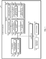
FIG. 1 is a simplified block diagram of at least one embodiment of a compute device for caching persistent two-level memory (2LM) data; -
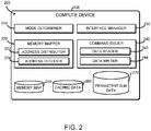
FIG. 2 is a simplified block diagram of at least one embodiment of an environment that may be established by the compute device ofFIG. 1 ; -
FIG. 3 is a simplified flow diagram of at least one embodiment of a method for setting up caching for persistent 2LM data that may be executed by the compute device ofFIGS. 1 and2 ; -
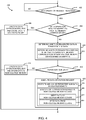
FIG. 4 is a simplified flow diagram of at least one embodiment of a method for performing a persistent 2LM data operation that may be executed by the compute device ofFIGS. 1 and2 ; and -
FIG. 5 is a simplified flow diagram of at least one embodiment of a method for system shutdown that may be executed by the compute device ofFIGS. 1 and2 . - While the concepts of the present disclosure are susceptible to various modifications and alternative forms, specific embodiments thereof have been shown by way of example in the drawings and will be described herein in detail. It should be understood, however, that there is no intent to limit the concepts of the present disclosure to the particular forms disclosed, but on the contrary, the intention is to cover all modifications, equivalents, and alternatives consistent with the present disclosure and the appended claims.
- References in the specification to "one embodiment," "an embodiment," "an illustrative embodiment," etc., indicate that the embodiment described may include a particular feature, structure, or characteristic, but every embodiment may or may not necessarily include that particular feature, structure, or characteristic. Moreover, such phrases are not necessarily referring to the same embodiment. Further, when a particular feature, structure, or characteristic is described in connection with an embodiment, it is submitted that it is within the knowledge of one skilled in the art to effect such feature, structure, or characteristic in connection with other embodiments whether or not explicitly described. Additionally, it should be appreciated that items included in a list in the form of "at least one A, B, and C" can mean (A); (B); (C); (A and B); (A and C); (B and C); or (A, B, and C). Similarly, items listed in the form of "at least one of A, B, or C" can mean (A); (B); (C); (A and B); (A and C); (B and C); or (A, B, and C).
- The disclosed embodiments may be implemented, in some cases, in hardware, firmware, software, or any combination thereof. The disclosed embodiments may also be implemented as instructions carried by or stored on a transitory or non-transitory machine-readable (e.g., computer-readable) storage medium, which may be read and executed by one or more processors. A machine-readable storage medium may be embodied as any storage device, mechanism, or other physical structure for storing or transmitting information in a form readable by a machine (e.g., a volatile or non-volatile memory, a media disc, or other media device).
- In the drawings, some structural or method features may be shown in specific arrangements and/or orderings. However, it should be appreciated that such specific arrangements and/or orderings may not be required. Rather, in some embodiments, such features may be arranged in a different manner and/or order than shown in the illustrative figures. Additionally, the inclusion of a structural or method feature in a particular figure is not meant to imply that such feature is required in all embodiments and, in some embodiments, may not be included or may be combined with other features.
- As shown in
FIG. 1 , anillustrative compute device 100 for caching persistent two-level memory (2LM) data includes aprocessor 102 and amemory 104, which is partitioned into two levels. One level, referred to as the "near memory", includesvolatile memory 130. The second level, referred to as the "far memory", is embodied as a relatively slower memory (e.g., lower bandwidth and/or higher latency) as compared to the near memory (e.g., the volatile memory 130) and, in the illustrative embodiment, comprisesnon-volatile memory 140. In other embodiments, the far memory may be volatile. The far memory is presented to an operating system executed by theprocessor 102 as main memory, while the near memory is transparent to the operating system. In operation, and as explained in more detail herein, the near memory may act as a cache for the far memory, providing theprocessor 102 with faster access to data than would be possible if the data was only present in the far memory. Further, and as described in more detail below, in use, theprocessor 102 is configured to set up caching of persistent data associated with anapplication 122 that is mapped to a persistent memory address space of thenon-volatile memory 140. To do so, theprocessor 102 configures the persistent memory address space to operate in a persistent two-level memory (2LM) mode. As described further below, the persistent 2LM mode provides direct access to thenon-volatile memory 140 to store and/or load the persistent 2LM data and further allows the operating system to cache accesses to the persistent memory address space in thevolatile memory 130 without implementing any changes to hardware components of thecompute device 100. - The
processor 102 may be embodied as any type of processor capable of performing the functions described herein. For example, theprocessor 102 may be embodied as a single or multi-core processor(s), digital signal processor, field programmable gate arrays (FPGA), microcontroller, or other processor or processing/controlling circuit. Similarly, thememory 104 may be embodied as any type of volatile and/or non-volatile memory or data storage capable of performing the functions described herein. In some embodiments, theprocessor 102 and thememory 104 may form a portion of a system-on-a-chip (SoC) and be incorporated, along with other components of thecompute device 100, onto a single integrated circuit chip. - The
memory 104 is communicatively coupled to theprocessor 102 via the I/O subsystem 106, which may be embodied as circuitry and/or components to facilitate input/output operations with theprocessor 102, thememory 104, and other components of thecompute device 100. For example, the I/O subsystem 106 may be embodied as, or otherwise include, memory controller hubs, input/output control hubs, firmware devices, communication links (i.e., point-to-point links, bus links, wires, cables, light guides, printed circuit board traces, etc.) and/or other components and subsystems to facilitate the input/output operations. In some embodiments, the I/O subsystem 106 may form a portion of a system-on-a-chip (SoC) and be incorporated, along with theprocessor 102, thememory 104, and other components of thecompute device 100, on a single integrated circuit chip. - The
internal memory controller 120 may be embodied as any type of control device, circuitry, or collection of hardware devices capable of writing, reading, locating, and replacing data in thememory 104. In the illustrative embodiment, theinternal memory controller 120 is configured to control memory access to thevolatile memory 130 and thenon-volatile memory 140. To do so, theinternal memory controller 120 may control a source address decoder and a target address decoder of theprocessor 102 by converting between different modes of operation for a memory address space. It should be appreciated that a memory address space is a set of discrete logical addresses, each of which may correspond to a different physical memory address in thevolatile memory 130 and/or the non-volatilememory 140. By configuring modes of operation for the logical addresses, theinternal memory controller 120 may control memory access to one or more volatile andnon-volatile memory devices non-volatile memory 140. - The
memory 104 may be embodied as any type of data storage capable of storing data. In the illustrative embodiment, thememory 104 includes thevolatile memory 130 controlled by thevolatile memory controller 134 and thenon-volatile memory 140 controlled by thenon-volatile memory controller 144. It should be appreciated that thevolatile memory controller 134 and thenon-volatile memory controller 144 are configured to communicate with theinternal memory controller 120. For example, thevolatile memory controller 134 is configured to receive application data instructions to execute and cache the application data in thevolatile memory 130. On the other hand, thenon-volatile memory controller 134 is configured to receive application data instructions to execute and store the application data in thenon-volatile memory 140. In some embodiments, theVM controller 134 and/or theNVM controller 144 may form portions of other components of thecompute device 100, such as the I/O subsystem 106. - The
volatile memory 130 may be embodied as any type of data storage capable of storing data while power is supplied to thevolatile memory 130. For example, in the illustrative embodiment, thevolatile memory 130 is embodied as one or morevolatile memory devices 132, and is periodically referred to hereinafter asvolatile memory 130 with the understanding that thevolatile memory 130 may be embodied as other types of non-persistent data storage in other embodiments. The volatile memory devices of thevolatile memory 130 may be embodied as any storage medium that requires power to maintain the state of data stored by the medium. Non-limiting examples of volatile memory may include various types of random access memory (RAM), such as dynamic random access memory (DRAM) or static random access memory (SRAM). One particular type of DRAM that may be used in a memory module is synchronous dynamic random access memory (SDRAM). In particular embodiments, DRAM of a memory component may comply with a standard promulgated by JEDEC, such as JESD79F for DDR SDRAM, JESD79-2F for DDR2 SDRAM, JESD79-3F for DDR3 SDRAM, JESD79-4A for DDR4 SDRAM, JESD209 for Low Power DDR (LPDDR), JESD209-2 for LPDDR2, JESD209-3 for LPDDR3, and JESD209-4 for LPDDR4 (these standards are available at www.jedec.org). Such standards (and similar standards) may be referred to as DDR-based standards and communication interfaces of the storage devices that implement such standards may be referred to as DDR-based interfaces. - The
non-volatile memory 140 may be embodied as any type of data storage capable of storing data in a persistent manner, even if power is interrupted to non-volatilememory 140. For example, in the illustrative embodiment, thenon-volatile memory 140 is embodied as one or morenon-volatile memory devices 142. Thenon-volatile memory devices 142 are illustratively embodied as byte or block-addressable, write-in-place non-volatile memory devices. In some embodiments, thenon-volatile memory devices 142 may be arranged in ranks. It should be appreciated that thenon-volatile memory devices 142 in each rank are connected to the same communication channel. - Each
non-volatile memory device 142 may be embodied as a block addressable memory device, such as those based on NAND or NOR technologies. Anon-volatile memory device 142 may also include future generation nonvolatile devices, such as a three dimensional crosspoint memory device, or other byte addressable write-in-place nonvolatile memory devices. In one embodiment, anon-volatile memory device 142 may be or may include memory devices that use chalcogenide glass, multi-threshold level NAND flash memory, NOR flash memory, single or multi-level Phase Change Memory (PCM), a resistive memory, nanowire memory, ferroelectric transistor random access memory (FeTRAM), anti-ferroelectric memory, magnetoresistive random access memory (MRAM) memory that incorporates memristor technology, resistive memory including the metal oxide base, the oxygen vacancy base and the conductive bridge Random Access Memory (CB-RAM), or spin transfer torque (STT)-MRAM, a spintronic magnetic junction memory based device, a magnetic tunneling junction (MTJ) based device, a DW (Domain Wall) and SOT (Spin Orbit Transfer) based device, a thiristor based memory device, or a combination of any of the above, or other memory. The memory device may refer to the die itself and/or to a packaged memory product. In some embodiments, 3D crosspoint memory may comprise a transistor-less stackable cross point architecture in which memory cells sit at the intersection of word lines and bit lines and are individually addressable and in which bit storage is based on a change in bulk resistance. - The
data storage device 108 may be embodied as any type of device or devices configured for short-term or long-term storage of data such as, for example, memory devices and circuits, memory cards, hard disk drives, solid-state drives, or other data storage devices. Thedata storage device 108 may be incorporated in, or form a portion of, one or more other components of thecomputing device 100. For example, thedata storage device 108 may be embodied as, or otherwise be included in, themain memory 104. Additionally or alternatively, thedata storage device 108 may be embodied as, or otherwise included in, a solid state drive of thecomputing device 100. Further, in some embodiments, thedata storage device 108 may be embodied as, or otherwise included in, a hard disk drive of thecomputing device 100. Of course, in other embodiments, thedata storage device 108 may be included in or form a portion of other components of thecomputing device 100. - The
peripheral devices 110 may include any number of input/output devices, user interface devices, and/or externally connected peripheral devices. For example, in some embodiments, theperipheral devices 110 may include a display, touch screen, graphics circuitry, keypad, keyboard, mouse, speaker system, and/or other input/output devices, interface devices, and/or peripheral devices. Additionally or alternatively, theperipheral devices 110 may include one or more ports, such as a USB port, for example, for connecting external peripheral devices to thecomputing device 100. - Referring now to
FIG. 2 , in use, thecompute device 100 may establish anenvironment 200. Theillustrative environment 200 includes amode determiner 210, amemory mapper 220, aninterface manager 230, and acommand issuer 240. Thememory mapper 220 further includes anaddress distributor 222 and anaddress decoder 224. Further, thecommand issuer 240 includes adata reader 242 and adata writer 244. Additionally, theillustrative environment 200 includes amemory map 250, cacheddata 260, andpersistent 2LM data 270. Each of the components of theenvironment 200 may be embodied as firmware, software, hardware, or a combination thereof. For example the logic and other components of theenvironment 200 may form a portion of, or otherwise be established by, thecompute device 100 or other hardware components of thecompute device 100. As such, in some embodiments, any one or more of the components of theenvironment 200 may be embodied as a circuit or collection of electrical devices (e.g., a memorymode determiner circuit 210, amemory mapper circuit 220, aninterface manager circuit 230, acommand issuer circuit 240, etc.). - The
mode determiner 210, which may be embodied as hardware, firmware, software, virtualized hardware, emulated architecture, and/or a combination thereof as described above, is configured to determine different configurable modes of operation for memory addresses within a memory address space. As described above, the memory address space includes a set of logical addresses that correspond to physical addresses in thevolatile memory 130 and/or thenon-volatile memory 140. By configuring modes of operation for each logical memory address or ranges thereof, themode determiner 210 may control memory access to one or more of the volatile andnon-volatile memory devices - In use, when the
internal memory controller 120 receives a data instruction (e.g., write or read) from theapplication 122 that is mapped to a memory address space, theinternal memory controller 120 may determine which memory (i.e.,volatile memory 130 or non-volatile memory 140) to access for executing the data instruction based on the mode of operation for the memory address space. For example, if the memory address of the requested data instruction is mapped to the volatile memory address space operable in the caching mode, the requested data instruction is directed to thevolatile memory 130 for execution. If, however, the memory address of the requested data instruction is mapped to the non-volatile memory address space operable in the non-caching memory mode, the requested data instruction bypasses thevolatile memory 130 and is directed to thenon-volatile memory 140 for execution. Alternatively, if the memory address of the requested data instruction is mapped to the persistent memory address space operable in the persistent 2LM mode, the requested data instruction is directed to thevolatile memory 130 and/or thenon-volatile memory 140 for execution, as described in detail below. - The
memory mapper 220, which may be embodied as hardware, firmware, software, virtualized hardware, emulated architecture, and/or a combination thereof as described above, is configured to generate amemory map 250 that includes memory address spaces within a main memory address space and corresponding modes of operation. As described below, in the illustrative embodiment, thememory map 250 is used to determine whether an application data instruction received from an application requires the application data to be persistent after execution. For example, thememory map 250 may indicate whether a memory address that an application data instruction is mapped to is configured to operate in the caching mode, the non-caching memory mode, or the persistent 2LM mode. To do so, thememory mapper 220 includes theaddress distributor 222 and theaddress decoder 224. - The
address distributor 222, in the illustrative embodiment, is configured to set up an address interleave to map contiguous logical memory addresses to physical addresses that are distributed across multiple memory devices (e.g., multiplevolatile memory devices 132 or multiple non-volatile memory devices 142). For example, a first logical memory address may map to a first physical memory address in one of thevolatile memory devices 132 and the second logical memory address may map to a second physical memory address in a second of thevolatile memory devices 132, and so on. - The
address decoder 224 is configured to alter a memory mode of the memory address space to a different memory mode, such that the operating system can use the memory address space that is configured to operate in one memory mode as another memory mode without implementing any changes to hardware components of thecompute device 100. For example, in the illustrative embodiment, theaddress decoder 224 allows theprocessor 102 and software to use the memory address space that is configured to operate in the persistent 2LM mode as the cached volatile memory such that memory accesses are cached in the persistent memory address space in thevolatile memory 130. - In use, when the
internal memory controller 120 receives a data request from theapplication 122, thememory mapper 220 determines a memory address space that the application data instruction is mapped to, and further determines which memory mode corresponds to the determined memory address space. For example, if thememory mapper 220 determines that a logical address associated with a requested data instruction is mapped to a memory address space that is configured to operate in the caching mode, theinternal memory controller 120 forwards the requested data instruction to thevolatile memory controller 134 to access the corresponding physical address of thevolatile memory 130 to perform the requested data instruction (i.e., write data to or read data from the volatile memory 130) for execution. - If, however, the
memory mapper 220 determines that the requested data instruction is mapped to a memory address space that is configured to operate in the non-caching memory mode, theinternal memory controller 120 forwards the requested data instruction to thenon-volatile memory controller 144 to access the corresponding physical memory address of thenon-volatile memory 140 to perform the requested data instruction (i.e., write data to or read data from the non-volatile memory 140). - Alternatively, if the
memory mapper 220 determines that the requested data instruction is mapped to a memory address space that is configured to operate in the persistent 2LM mode, theinternal memory controller 120 may forward the requested data instruction to thenon-volatile memory controller 144 and thevolatile memory controller 134. As such, the requested data instruction may be executed in the volatile andnon-volatile memory 130, 140 (i.e., write persistent data to or read persistent data from the volatile andnon-volatile memory 130, 140), which is described in detail below. - The
interface manager 230 is configured to handle various instructions, including but not limited to, data storage instructions and data read instructions received from a host, which may be embodied as an application, service, and/or other device. In some embodiments, theinterface manager 230 may be configured to handle other instructions as well, including self-monitoring, analysis and reporting technology ("SMART") instructions, and other instructions defined in the non-volatile memory express ("NVMe") specification. NVMe is a logical device interface for accessing non-volatile storage media attached via a Peripheral Component Interconnect Express (PCIe) bus. The non-volatile storage media may comprise a flash memory and solid solid-state drives (SSDs). It should be appreciated that NVMe is designed for accessing low latency storage devices in computer systems, including personal and enterprise computer systems, and is also deployed in data centers requiring scaling of thousands of low latency storage devices. To handle the various instructions, theinterface manager 230 is configured to identify a received instruction and any data and/or parameters associated with the instruction, and transmit those items to themode determiner 210. For example, in response to a read instruction, theinterface manager 230 transmits the data read by thedata manager 230 to the host. - The
command issuer 240, which may be embodied as hardware, firmware, software, virtualized hardware, emulated architecture, and/or a combination thereof, is configured to manage the reading of data from and writing of data to thevolatile memory devices 132 of thevolatile memory 130 and/or thenon-volatile memory devices 142 of thenon-volatile memory 140. To do so, thecommand issuer 240 includes thedata reader 242 and thedata writer 244. - The
data reader 242 is configured to read data from a volatile memory device(s) 132 and/or a non-volatile memory device(s) 142 in response to an application read instruction. As described above, whether to access thevolatile memory 130 or thenon-volatile memory 140 depends on the memory address of the requested application read instruction. - The
data writer 244 is configured to write data to a volatile memory device(s) 132 and/or a non-volatile memory device(s) 142 in response to an application write instruction. As described above, whether to access thevolatile memory 130 or thenon-volatile memory 140 depends on the memory address of the requested application write instruction. - Additionally, the
illustrative environment 200 includesmemory map data 250, cacheddata 260, andpersistent 2LM data 270. Thememory map data 250 may be embodied as any data indicative of one or more memory maps that include memory address space(s) and corresponding mode(s) of operation. Thememory map 250 may be accessed by the modules and/or sub-modules of thecompute device 100. - The cached
data 260 may be embodied as any cached data that resulted from execution of an application data instruction and stored in thevolatile memory 130. For example, as described above, the application data instruction, which is mapped to a memory address space that is operable in the caching mode and/or the persistent 2LM mode, is executed and cached in thevolatile memory 130. - The
persistent 2LM data 270 may be embodied as any data that resulted from execution of a persistent 2LM data instruction and stored in thenon-volatile memory 140 upon execution. For example, as described above, the application data instruction, which is mapped to a memory address space that is operable in the persistent 2LM mode, is executed and stored in thenon-volatile memory 140. - Referring now to
FIG. 3 , in use, theprocessor 102 may execute amethod 300 for configuring an operating system executed by thecompute device 100 to cache accesses to the persistent memory address space in thevolatile memory 130. Themethod 300 begins atblock 302 in which theprocessor 102 determines whether to set up caching for application data that is to be persistent by configuring a mode of operation for the corresponding memory address space. In some embodiments, theprocessor 102 determines whether to set up caching for persistent 2LM data based on a type of an application and/or a type of application data. If theprocessor 102 determines not to set up caching for persistent 2LM data, themethod 300 loops back to block 302 to continue determining whether to set up caching for persistent 2LM data. - If, however, the
processor 102 determines to set up caching for persistent 2LM data, themethod 300 advances to block 304. Inblock 304, theprocessor 102 determines a persistent memory address space within the non-volatile memory address space for storage of persistent data and further determines one or more corresponding non-volatile memory devices that are configured to contain the persistent memory address space. In other words, theprocessor 102 determines one or more non-volatile memory devices that are configured to contain persistent 2LM data. - In
block 306, theprocessor 102 configures the determined persistent memory address space of the determined non-volatile memory device(s) to operate in a persistent 2LM mode. In some embodiments, theprocessor 102 may set up an address interleave to allocate memory addresses of the memory address space across multiplenon-volatile memory devices 142 inblock 308. Alternatively, theprocessor 102 may update an existing address interleave to further allocate memory addresses of the persistent memory address space across multiplenon-volatile memory devices 142. - Additionally or alternatively, in some embodiments, in
block 310, theprocessor 102 may generate an address map that includes memory addresses and a corresponding mode of operation for each memory address. Alternatively, theprocessor 102 may update an existing address map to update those memory addresses that are now configured to operate in the persistent 2LM mode. For example, as described above, the address map may indicate whether a memory address included in the application data instruction is configured to operate in the caching mode, the non-caching memory mode, or the persistent 2LM mode. As described above, an application data instruction that includes a memory address that is mapped to the non-volatile memory address space is generally directed to thenon-volatile memory 140 for execution and persistent storage. On the other hand, an application data instruction that includes a memory address that is mapped to the persistent memory address space is directed to both thenon-volatile memory 140 for persistent storage and thevolatile memory 130 for caching the persistent 2LM data. - Additionally or alternatively, in some embodiments, the
processor 102 may set up at least one block window that defines at least one address range for accessing one or more blocks of the persistent 2LM data storable within the non-volatile memory device(s) 142. - In
block 312, theprocessor 102 and software are configured to cache accesses to the persistent memory address space in thevolatile memory 130. In other words, theprocessor 102 is configured to cache the persistent 2LM data involatile memory 130, while treating the persistent 2LM data pursuant to the persistent 2LM mode innon-volatile memory 140. To do so, inblock 314, theprocessor 102 is configured to cache the persistent 2LM data in thevolatile memory 130. In some embodiments, inblock 316, theinternal memory controller 102 of theprocessor 102 may configure one or more address decoders to change the mode of operation of the memory address. For example, the address decoder may convert the persistent 2LM mode of the persistent memory address space to the caching memory mode. - In
block 318, theprocessor 102 further reports the persistent memory address space as a volatile region to the operating system, such that the application instruction mapped to the persistent memory address space is executed and the corresponding data is cached in thevolatile memory 130. - In
block 320, theprocessor 102 tracks the persistent memory address space and cached volatile memory address space. Theprocessor 102 is configured to generate a memory management mapping of the persistent memory address space and the volatile memory address space to keep track of the persistent 2LM data. Inblock 322, theprocessor 102 updates the memory management mapping. - Referring now to
FIG. 4 , in use, theprocessor 102 of thecompute device 100 may execute amethod 400 for executing a persistent 2LM data instruction. Themethod 400 begins atblock 402 in which theprocessor 102 determines whether a data operation request has been received. If theprocessor 102 determines that a data operation request has not been received, themethod 400 loops back to block 402 to continue monitoring for an application data operation request. If, however, theprocessor 102 determines that the data operation request has been received, themethod 400 advances to block 404. - In
block 404, theinternal memory controller 120 determines whether the memory address of the received data operation request is mapped to the volatile memory address space. If theprocessor 102 determines that the data operation request is mapped to the volatile memory address space, themethod 400 advances to block 406 in which theprocessor 102 performs the data operation request and caches the requested data in the correspondingvolatile memory device 132 of thevolatile memory 130 based on the address map. - If, however, if the
processor 102 determines that the data operation request is not mapped to the volatile memory address space, themethod 400 advances to block 408. Inblock 408, theprocessor 102 determines whether the requested data is persistent 2LM data. To do so, inblock 410, theprocessor 102 determines whether the memory address of the requested data is mapped to a persistent memory address space of thenon-volatile memory device 142 based on the address map. - If the
processor 102 determines that the requested data is not persistent 2LM data in block 412 (e.g., the memory address of the requested data is not mapped to the persistent memory address space), themethod 400 advances to block 414. Inblock 414, theprocessor 102 executes the data operation request and stores the requested data in the correspondingnon-volatile memory device 142 of thenon-volatile memory 140. - If, however, the
processor 102 determines that the requested data is persistent 2LM data inblock 412, themethod 400 advances to block 416. Inblock 416, theprocessor 102 executes the received data operation request. To do so, inblock 418, theinternal memory controller 120 of theprocessor 102 directs the data operation request to thevolatile memory controller 134 to execute the data operation request and cache the persistent 2LM data in the correspondingvolatile memory device 132 of thevolatile memory 130. - Additionally, in
block 420, theinternal memory controller 120 of theprocessor 102 directs the data operation request to thenon-volatile memory controller 144 to execute the data operation request and store the persistent 2LM data in the correspondingnon-volatile memory device 142 of thenon-volatile memory 140. For example, inblock 422, thenon-volatile memory controller 144 may write persistent 2LM data that was cached in thevolatile memory 130 to the corresponding address of thenon-volatile memory device 142 of thenon-volatile memory 140 in response to a receipt a write data instruction from an application. - Alternatively, in
block 422, thenon-volatile memory controller 144 may read persistent 2LM data from the corresponding address of thenon-volatile memory device 142 of thenon-volatile memory 140 in response to a receipt a read data instruction from an application. - In some embodiments, the persistent 2LM data stored in the
volatile memory 130 may be written to thenon-volatile memory 140 in case of an overflow of thevolatile memory 130. In other embodiments, the requested persistent 2LM data may be read from thenon-volatile memory 140 if the persistent 2LM data is not found in thevolatile memory 130. - In some embodiments, the persistent 2LM data may be committed to the
non-volatile memory 140 from thevolatile memory 130 in response to a receipt of a shutdown signal, which is described in detail inFIG. 5 . Additionally or alternatively, the persistent 2LM data may be periodically committed to thenon-volatile memory 140 from thevolatile memory 130. - Referring now to
FIG. 5 , in use, theprocessor 102 of thecompute device 100 may execute amethod 500 for flushing thepersistent 2LM data 270 cached in thevolatile memory 130 to thenon-volatile memory 140. Themethod 500 begins atblock 502 in which theprocessor 102 determines whether a system shutdown request has been received. If theprocessor 102 determines that a system shutdown request has not been received, themethod 500 loops back to block 502 to continue monitoring for a system shutdown request. If, however, theprocessor 102 determines that the system shutdown request has been received, themethod 500 advances to block 504. - In
block 504, theprocessor 102 issues a write-back and flush operation request prior to shutting down the system. Inblock 506, in response to a receipt of the write-back and flush operation request, theprocessor 102 flushes thepersistent 2LM data 270 stored in thevolatile memory 130 to thenon-volatile memory 140. To do so, in some embodiments, theprocessor 102 may serialize and perform any and all data queued instructions received prior to the shut down request, as indicated inblock 508. Once the instructions in the queue are drained, theprocessor 102 may read the volatile memory addresses to flush all modified cached data of the persistent memory address space to thenon-volatile memory 140 inblock 510. Once thepersistent 2LM data 270 cached in thevolatile memory 130 is stored in thenon-volatile memory 140, themethod 500 advances to block 512 to shut down the system. - Reference to memory devices can apply to different memory types, and in particular, any memory that has a bank group architecture. Memory devices generally refer to volatile memory technologies. Volatile memory is memory whose state (and therefore the data stored on it) is indeterminate if power is interrupted to the device. Nonvolatile memory refers to memory whose state is determinate even if power is interrupted to the device. Dynamic volatile memory requires refreshing the data stored in the device to maintain state. One example of dynamic volatile memory includes DRAM (dynamic random access memory), or some variant such as synchronous DRAM (SDRAM). A memory subsystem as described herein may be compatible with a number of memory technologies, such as DDR4 (DDR version 4, initial specification published in September 2012 by JEDEC), DDR4E (in development by JEDEC), LPDDR4 (LOW POWER DOUBLE DATA RATE (LPDDR) version 4, JESD209-4, originally published by JEDEC in August 2014), WIO2 (Wide I/O 2 (WideIO2), JESD229-2, originally published by JEDEC in August 2014), HBM (HIGH BANDWIDTH MEMORY DRAM, JESD235, originally published by JEDEC in October 2013), DDR5 (DDR version 5, currently in discussion by JEDEC), LPDDR5 (currently in discussion by JEDEC), HBM2 (HBM version 2), currently in discussion by JEDEC), and/or others, and technologies based on derivatives or extensions of such specifications.
- In addition to, or alternatively to, volatile memory, in one embodiment, reference to memory devices can refer to a nonvolatile memory device whose state is determinate even if power is interrupted to the device.
- Illustrative examples of the technologies disclosed herein are provided below. An embodiment of the technologies may include any one or more, and any combination of, the examples described below.
- Example 1 includes a compute device for caching persistent two-level memory (2LM) data comprising a memory including one or more volatile memory devices and one or more non-volatile memory devices; and a processor to determine a persistent memory address space for persistent 2LM data and one or more non-volatile memory devices that the persistent memory address space is mapped to, wherein each non-volatile memory device contains the persistent 2LM data; configure the persistent memory address space of the non-volatile memory device to operate in a persistent two-level memory (2LM) mode in which application data written to the persistent memory address space is reusable across power cycles; and configure an operating system to cache accesses to the persistent memory address space in the volatile memory.
- Example 2 includes the subject matter of Example 1, and wherein to configure the operating system to cache the accesses to the persistent memory address space in the volatile memory comprises to configure an address decoder to convert from a first mode of operation for the persistent memory address space to a second mode of operation for the persistent memory address space.
- Example 3 includes the subject matter of any of Examples 1 and 2, and wherein the first mode of operation is the persistent 2LM mode for storing the persistent 2LM data in the non-volatile memory, and the second mode of operation is a caching mode for caching the persistent 2LM data in one or more of the volatile memory devices.
- Example 4 includes the subject matter of any of Examples 1-3, and wherein the processor is further to receive a write data instruction to write application data; determine whether the write data instruction requires the application data to be persistent; execute, in response to a determination that the application data is persistent, the write data instruction to a memory address of the write data instruction; cache the persistent 2LM data in a corresponding volatile memory; and store the persistent 2LM data in a corresponding non-volatile memory device.
- Example 5 includes the subject matter of any of Examples 1-4, and wherein to determine whether the application data is required to be persistent comprises to determine whether the memory address of the write data instruction is mapped to a persistent memory address space that is configured to operate in the persistent 2LM mode.
- Example 6 includes the subject matter of any of Examples 1-5, and wherein to store the application data in the non-volatile memory device comprises to store application data that is modified and cached in the volatile memory device to the non-volatile memory device.
- Example 7 includes the subject matter of any of Examples 1-6, and wherein the processor is further to receive a read data instruction to read application data; determine whether the read data instruction requires the application data to be persistent; execute, in response to a determination that the application data is required to be persistent, the read data instruction to a memory address of the read data instruction; and cache the application data in a corresponding volatile memory device.
- Example 8 includes the subject matter of any of Examples 1-7, and wherein to determine one or more non-volatile memory devices that the persistent memory address space is mapped to comprises to determine one or more non-volatile write-in-place byte addressable memory devices that the persistent memory address space is mapped to.
- Example 9 includes the subject matter of any of Examples 1-8, and wherein the processor is further to set up an address interleave that maps contiguous logical memory addresses across multiple non-contiguous physical addresses of the one or more non-volatile memory devices.
- Example 10 includes the subject matter of any of Examples 1-9, and wherein the processor is further to detect a system shut down request, and write, in response to the detection of the system shut down request, application data from the one or more volatile memory devices to the one or more non-volatile memory devices.
- Example 11 includes the subject matter of any of Examples 1-10, and wherein the processor is further to serialize and perform data instructions in a queue in response to the detection of the system shut down request.
- Example 12 includes a method for caching persistent two-level memory (2LM) data comprising determining, by a compute device, a persistent memory address space for persistent 2LM data and one or more non-volatile memory devices that the persistent memory address space is mapped to, wherein each non-volatile memory device contains the persistent 2LM data; configuring, by the compute device, the persistent memory address space of the non-volatile memory device to operate in a persistent two-level memory (2LM) mode in which application data written to the persistent memory address space is reusable across power cycles; and configuring, by the compute device, an operating system to cache accesses to the persistent memory address space in the volatile memory.
- Example 13 includes the subject matter of Example 12, and wherein configuring the operating system to cache the accesses to the persistent memory address space in the volatile memory comprises configuring an address decoder to convert from a first mode of operation for the persistent memory address space to a second mode of operation for the persistent memory address space.
- Example 14 includes the subject matter of any of Examples 12 and 13, and wherein the first mode of operation is the persistent 2LM mode for storing the persistent 2LM data in the non-volatile memory, and the second mode of operation is a caching mode for caching the persistent 2LM data in one or more of the volatile memory devices. 15 The method of claim 12 further comprising receiving, by the compute device, a write data instruction to write application data; determining, by the compute device, whether the write data instruction requires the application data to be persistent; executing, by the compute device and in response to a determination that the application data is persistent, the write data instruction to a memory address of the write data instruction; caching, by the compute device, the persistent 2LM data in a corresponding volatile memory; and storing, by the compute device, the persistent 2LM data in a corresponding non-volatile memory device.
- Example 16 includes the subject matter of any of Examples 12-15, and wherein determining whether the application data is required to be persistent comprises determining whether the memory address of the write data instruction is mapped to a persistent memory address space that is configured to operate in the persistent 2LM mode.
- Example 17 includes the subject matter of any of Examples 12-16, and wherein storing the application data in the non-volatile memory device comprises storing application data that is modified and cached in the volatile memory device to the non-volatile memory device.
- Example 18 includes the subject matter of any of Examples 12-17, and further including receiving, by the compute device, a read data instruction to read application data; determining, by the compute device, whether the read data instruction requires the application data to be persistent; executing, by the compute device and in response to a determination that the application data is required to be persistent, the read data instruction to a memory address of the read data instruction; and caching, by the compute device, the application data in a corresponding volatile memory device.
- Example 19 includes the subject matter of any of Examples 12-18, and wherein determining one or more non-volatile memory devices that the persistent memory address space is mapped to comprises determining one or more non-volatile write-in-place byte addressable memory devices that the persistent memory address space is mapped to.
- Example 20 includes the subject matter of any of Examples 12-19, and further including setting up an address interleave that maps contiguous logical memory addresses across multiple non-contiguous physical addresses of the one or more non-volatile memory devices.
- Example 21 includes the subject matter of any of Examples 12-20, and further including detecting a system shut down request, and writing, in response to the detection of the system shut down request, application data from the one or more volatile memory devices to the one or more non-volatile memory devices.
- Example 22 includes the subject matter of any of Examples 12-21, and further including serializing and performing data instructions in a queue in response to the detection of the system shut down request.
- Example 23 includes one or more machine-readable storage media comprising a plurality of instructions stored thereon that, when executed by a processor, cause the processor to perform the method of any of Examples 12-22.
- Example 24 includes a compute device for caching persistent two-level memory (2LM) data, the compute device comprising one or more processors; one or more memory devices having stored therein a plurality of instructions that, when executed by the one or more processors, cause the compute device to perform the method of any of Examples 12-22.
- Example 25 includes a compute device comprising means for determining a persistent memory address space for persistent 2LM data and one or more non-volatile memory devices that the persistent memory address space is mapped to, wherein each non-volatile memory device contains the persistent 2LM data; means for configuring the persistent memory address space of the non-volatile memory device to operate in a persistent two-level memory (2LM) mode in which application data written to the persistent memory address space is reusable across power cycles; and means for configuring an operating system to cache accesses to the persistent memory address space in the volatile memory.
- Example 26 includes the subject matter of Example 25, and wherein the means for configuring the operating system to cache the accesses to the persistent memory address space in the volatile memory comprises means for configuring an address decoder to convert from a first mode of operation for the persistent memory address space to a second mode of operation for the persistent memory address space.
- Example 27 includes the subject matter of any of Examples 25 and 26, and wherein the first mode of operation is the persistent 2LM mode for storing the persistent 2LM data in the non-volatile memory, and the second mode of operation is a caching mode for caching the persistent 2LM data in one or more of the volatile memory devices. 28 The compute device of claim 25, further comprising means for receiving a write data instruction to write application data; means for determining whether the write data instruction requires the application data to be persistent; means for executing, in response to a determination that the application data is persistent, the write data instruction to a memory address of the write data instruction; means for caching the persistent 2LM data in a corresponding volatile memory; and means for storing the persistent 2LM data in a corresponding non-volatile memory device.
- Example 29 includes the subject matter of any of Examples 25-28, and wherein the means for determining whether the application data is required to be persistent comprises means for determining whether the memory address of the write data instruction is mapped to a persistent memory address space that is configured to operate in the persistent 2LM mode.
- Example 30 includes the subject matter of any of Examples 25-29, and wherein the means for storing the application data in the non-volatile memory device comprises means for storing application data that is modified and cached in the volatile memory device to the non-volatile memory device.
- Example 31 includes the subject matter of any of Examples 25-30, and further including means for receiving a read data instruction to read application data; means for determining whether the read data instruction requires the application data to be persistent; means for executing, in response to a determination that the application data is required to be persistent, the read data instruction to a memory address of the read data instruction; and means for caching the application data in a corresponding volatile memory device.
- Example 32 includes the subject matter of any of Examples 25-31, and wherein the means for determining one or more non-volatile memory devices that the persistent memory address space is mapped to comprises means for determining one or more non-volatile write-in-place byte addressable memory devices that the persistent memory address space is mapped to.
- Example 33 includes the subject matter of any of Examples 25-32, and further including means for setting up an address interleave that maps contiguous logical memory addresses across multiple non-contiguous physical addresses of the one or more non-volatile memory devices.
- Example 34 includes the subject matter of any of Examples 25-33, and further including means for detecting a system shut down request, and writing, in response to the detection of the system shut down request, application data from the one or more volatile memory devices to the one or more non-volatile memory devices.
- Example 35 includes the subject matter of any of Examples 25-34, and further including means for serializing and performing data instructions in a queue in response to the detection of the system shut down request.
Claims (15)
- A compute device for caching persistent two-level memory (2LM) data comprising:a memory including one or more volatile memory devices and one or more non-volatile memory devices; anda processor to:determine a persistent memory address space for persistent 2LM data and one or more non-volatile memory devices that the persistent memory address space is mapped to, wherein each non-volatile memory device contains the persistent 2LM data;configure the persistent memory address space of the non-volatile memory device to operate in a persistent two-level memory (2LM) mode in which application data written to the persistent memory address space is reusable across power cycles; andconfigure an operating system to cache accesses to the persistent memory address space in the volatile memory.
- The compute device of claim 1, wherein to configure the operating system to cache the accesses to the persistent memory address space in the volatile memory comprises to configure an address decoder to convert from a first mode of operation for the persistent memory address space to a second mode of operation for the persistent memory address space.
- The compute device of claim 2, wherein the first mode of operation is the persistent 2LM mode for storing the persistent 2LM data in the non-volatile memory, and the second mode of operation is a caching mode for caching the persistent 2LM data in one or more of the volatile memory devices.
- The compute device of claim 1, wherein the processor is further to:receive a write data instruction to write application data;determine whether the write data instruction requires the application data to be persistent;execute, in response to a determination that the application data is persistent, the write data instruction to a memory address of the write data instruction;cache the persistent 2LM data in a corresponding volatile memory; andstore the persistent 2LM data in a corresponding non-volatile memory device.
- The compute device of claim 4, wherein to determine whether the application data is required to be persistent comprises to determine whether the memory address of the write data instruction is mapped to a persistent memory address space that is configured to operate in the persistent 2LM mode.
- The compute device of claim 4, wherein to store the application data in the non-volatile memory device comprises to store application data that is modified and cached in the volatile memory device to the non-volatile memory device.
- The compute device of claim 1 wherein the processor is further to:receive a read data instruction to read application data;determine whether the read data instruction requires the application data to be persistent;execute, in response to a determination that the application data is required to be persistent, the read data instruction to a memory address of the read data instruction; andcache the application data in a corresponding volatile memory device.
- The compute device of claim 1, wherein the processor is further to detect a system shut down request, and write, in response to the detection of the system shut down request, application data from the one or more volatile memory devices to the one or more non-volatile memory devices.
- A method for caching persistent two-level memory (2LM) data comprising:determining, by a compute device, a persistent memory address space for persistent 2LM data and one or more non-volatile memory devices that the persistent memory address space is mapped to, wherein each non-volatile memory device contains the persistent 2LM data;configuring, by the compute device, the persistent memory address space of the non-volatile memory device to operate in a persistent two-level memory (2LM) mode in which application data written to the persistent memory address space is reusable across power cycles; andconfiguring, by the compute device, an operating system to cache accesses to the persistent memory address space in the volatile memory.
- The method of claim 9, wherein configuring the operating system to cache the accesses to the persistent memory address space in the volatile memory comprises configuring an address decoder to convert from a first mode of operation for the persistent memory address space to a second mode of operation for the persistent memory address space.
- The method of claim 10, wherein the first mode of operation is the persistent 2LM mode for storing the persistent 2LM data in the non-volatile memory, and the second mode of operation is a caching mode for caching the persistent 2LM data in one or more of the volatile memory devices.
- The method of claim 9 further comprising:receiving, by the compute device, a write data instruction to write application data;determining, by the compute device, whether the write data instruction requires the application data to be persistent;executing, by the compute device and in response to a determination that the application data is persistent, the write data instruction to a memory address of the write data instruction;caching, by the compute device, the persistent 2LM data in a corresponding volatile memory; andstoring, by the compute device, the persistent 2LM data in a corresponding non-volatile memory device.
- The method of claim 12, wherein determining whether the application data is required to be persistent comprises determining whether the memory address of the write data instruction is mapped to a persistent memory address space that is configured to operate in the persistent 2LM mode.
- The method of claim 9 further comprising:receiving, by the compute device, a read data instruction to read application data;determining, by the compute device, whether the read data instruction requires the application data to be persistent;executing, by the compute device and in response to a determination that the application data is required to be persistent, the read data instruction to a memory address of the read data instruction; andcaching, by the compute device, the application data in a corresponding volatile memory device.
- One or more machine-readable storage media comprising a plurality of instructions stored thereon that, when executed by a processor, cause the processor to perform the method of any of claims 9-14.
Applications Claiming Priority (1)
| Application Number | Priority Date | Filing Date | Title |
|---|---|---|---|
| US15/670,320 US20190042445A1 (en) | 2017-08-07 | 2017-08-07 | Technologies for caching persistent two-level memory data |
Publications (2)
| Publication Number | Publication Date |
|---|---|
| EP3441885A1 true EP3441885A1 (en) | 2019-02-13 |
| EP3441885B1 EP3441885B1 (en) | 2020-11-25 |
Family
ID=62874816
Family Applications (1)
| Application Number | Title | Priority Date | Filing Date |
|---|---|---|---|
| EP18182324.6A Active EP3441885B1 (en) | 2017-08-07 | 2018-07-06 | Technologies for caching persistent two-level memory data |
Country Status (3)
| Country | Link |
|---|---|
| US (1) | US20190042445A1 (en) |
| EP (1) | EP3441885B1 (en) |
| CN (1) | CN109388588B (en) |
Cited By (1)
| Publication number | Priority date | Publication date | Assignee | Title |
|---|---|---|---|---|
| EP4137951A4 (en) * | 2020-05-29 | 2023-10-04 | Huawei Technologies Co., Ltd. | Storage medium management method and apparatus, and device and computer-readable storage medium |
Families Citing this family (10)
| Publication number | Priority date | Publication date | Assignee | Title |
|---|---|---|---|---|
| US11144467B2 (en) | 2019-05-17 | 2021-10-12 | Intel Corporation | Bypassing cache memory in a write transaction in a system with multi-level memory |
| US12045644B2 (en) | 2019-05-24 | 2024-07-23 | Texas Instruments Incorporated | Pseudo-random way selection |
| US10789094B1 (en) * | 2019-08-22 | 2020-09-29 | Micron Technology, Inc. | Hierarchical memory apparatus |
| US11106595B2 (en) * | 2019-08-22 | 2021-08-31 | Micron Technology, Inc. | Hierarchical memory systems |
| US11169928B2 (en) * | 2019-08-22 | 2021-11-09 | Micron Technology, Inc. | Hierarchical memory systems to process data access requests received via an input/output device |
| US11016903B2 (en) * | 2019-08-22 | 2021-05-25 | Micron Technology, Inc. | Hierarchical memory systems |
| US12373335B2 (en) | 2019-12-26 | 2025-07-29 | Intel Corporation | Memory thin provisioning using memory pools |
| US11853605B2 (en) * | 2021-09-17 | 2023-12-26 | Micron Technology, Inc. | Database persistence |
| US11886744B2 (en) | 2021-12-15 | 2024-01-30 | Nvidia Corporation | Systems, methods, and apparatuses for making writes to persistent memory |
| CN116886719B (en) * | 2023-09-05 | 2024-01-23 | 苏州浪潮智能科技有限公司 | Data processing method and device of storage system, equipment and medium |
Citations (3)
| Publication number | Priority date | Publication date | Assignee | Title |
|---|---|---|---|---|
| JPH07146820A (en) * | 1993-04-08 | 1995-06-06 | Hitachi Ltd | Flash memory control method and information processing apparatus using the same |
| US20030204702A1 (en) * | 2002-04-30 | 2003-10-30 | Adc Dsl Systems, Inc. | Flexible memory architecture for an embedded processor |
| WO2013095437A1 (en) * | 2011-12-21 | 2013-06-27 | Intel Corporation | System and method for intelligently flushing data from a processor into a memory subsystem |
Family Cites Families (9)
| Publication number | Priority date | Publication date | Assignee | Title |
|---|---|---|---|---|
| US7620784B2 (en) * | 2006-06-09 | 2009-11-17 | Microsoft Corporation | High speed nonvolatile memory device using parallel writing among a plurality of interfaces |
| US9003159B2 (en) * | 2009-10-05 | 2015-04-07 | Marvell World Trade Ltd. | Data caching in non-volatile memory |
| US8694737B2 (en) * | 2010-06-09 | 2014-04-08 | Micron Technology, Inc. | Persistent memory for processor main memory |
| GB2510760B (en) * | 2011-12-20 | 2020-05-20 | Intel Corp | Dynamic partial power down of memory-side cache in a 2-level memory hierarchy |
| US9547594B2 (en) * | 2013-03-15 | 2017-01-17 | Intel Corporation | Instructions to mark beginning and end of non transactional code region requiring write back to persistent storage |
| CN105339908B (en) * | 2013-07-26 | 2018-09-11 | 英特尔公司 | Method and apparatus for supporting long-time memory |
| WO2015047348A1 (en) * | 2013-09-27 | 2015-04-02 | Intel Corporation | Cache operations for memory management |
| US9471494B2 (en) * | 2013-12-20 | 2016-10-18 | Intel Corporation | Method and apparatus for cache line write back operation |
| US10489158B2 (en) * | 2014-09-26 | 2019-11-26 | Intel Corporation | Processors, methods, systems, and instructions to selectively fence only persistent storage of given data relative to subsequent stores |
-
2017
- 2017-08-07 US US15/670,320 patent/US20190042445A1/en not_active Abandoned
-
2018
- 2018-07-06 EP EP18182324.6A patent/EP3441885B1/en active Active
- 2018-08-07 CN CN201810891545.4A patent/CN109388588B/en active Active
Patent Citations (3)
| Publication number | Priority date | Publication date | Assignee | Title |
|---|---|---|---|---|
| JPH07146820A (en) * | 1993-04-08 | 1995-06-06 | Hitachi Ltd | Flash memory control method and information processing apparatus using the same |
| US20030204702A1 (en) * | 2002-04-30 | 2003-10-30 | Adc Dsl Systems, Inc. | Flexible memory architecture for an embedded processor |
| WO2013095437A1 (en) * | 2011-12-21 | 2013-06-27 | Intel Corporation | System and method for intelligently flushing data from a processor into a memory subsystem |
Cited By (1)
| Publication number | Priority date | Publication date | Assignee | Title |
|---|---|---|---|---|
| EP4137951A4 (en) * | 2020-05-29 | 2023-10-04 | Huawei Technologies Co., Ltd. | Storage medium management method and apparatus, and device and computer-readable storage medium |
Also Published As
| Publication number | Publication date |
|---|---|
| CN109388588A (en) | 2019-02-26 |
| EP3441885B1 (en) | 2020-11-25 |
| US20190042445A1 (en) | 2019-02-07 |
| CN109388588B (en) | 2025-04-01 |
Similar Documents
| Publication | Publication Date | Title |
|---|---|---|
| EP3441885B1 (en) | Technologies for caching persistent two-level memory data | |
| KR102408149B1 (en) | Synchronous memory bus access to storage media | |
| US10379782B2 (en) | Host managed solid state drivecaching using dynamic write acceleration | |
| US9927999B1 (en) | Trim management in solid state drives | |
| US10943183B2 (en) | Electronics device performing software training on memory channel and memory channel training method thereof | |
| US10372446B2 (en) | Technology to dynamically modulate memory device read granularity | |
| US11307977B2 (en) | Technologies for direct matrix read and write operations | |
| US11720490B2 (en) | Managing host input/output in a memory system executing a table flush | |
| CN117916704A (en) | Unified sequencer concurrency controller for a memory subsystem | |
| KR20220153055A (en) | Setting the power mode based on the workload level of the memory subsystem | |
| CN115905057A (en) | Efficient buffer management for media management commands in a memory device | |
| CN117836751A (en) | Improving memory performance using a memory access command queue in a memory device | |
| US11199995B2 (en) | Time to live for load commands | |
| CN112313630A (en) | Dynamic memory deduplication to increase effective memory capacity | |
| US20240126448A1 (en) | Adaptive read disturb scan | |
| US20190041947A1 (en) | Technologies for dynamically managing power states of endpoint devices based on workload | |
| US11735272B2 (en) | Noise reduction during parallel plane access in a multi-plane memory device | |
| US12014080B2 (en) | Memory system using host memory buffer and operation method thereof | |
| US20250190147A1 (en) | Ultra-high endurance storage class memory to improve quality of service and energy requirements in a memory sub-system | |
| US12260110B2 (en) | Managing trim commands in a memory sub-system | |
| US20170372759A1 (en) | Active control circuit, internal voltage generation circuit, memory apparatus and system using the same |
Legal Events
| Date | Code | Title | Description |
|---|---|---|---|
| PUAI | Public reference made under article 153(3) epc to a published international application that has entered the european phase |
Free format text: ORIGINAL CODE: 0009012 |
|
| STAA | Information on the status of an ep patent application or granted ep patent |
Free format text: STATUS: THE APPLICATION HAS BEEN PUBLISHED |
|
| AK | Designated contracting states |
Kind code of ref document: A1 Designated state(s): AL AT BE BG CH CY CZ DE DK EE ES FI FR GB GR HR HU IE IS IT LI LT LU LV MC MK MT NL NO PL PT RO RS SE SI SK SM TR |
|
| AX | Request for extension of the european patent |
Extension state: BA ME |
|
| STAA | Information on the status of an ep patent application or granted ep patent |
Free format text: STATUS: REQUEST FOR EXAMINATION WAS MADE |
|
| 17P | Request for examination filed |
Effective date: 20190812 |
|
| RBV | Designated contracting states (corrected) |
Designated state(s): AL AT BE BG CH CY CZ DE DK EE ES FI FR GB GR HR HU IE IS IT LI LT LU LV MC MK MT NL NO PL PT RO RS SE SI SK SM TR |
|
| GRAP | Despatch of communication of intention to grant a patent |
Free format text: ORIGINAL CODE: EPIDOSNIGR1 |
|
| STAA | Information on the status of an ep patent application or granted ep patent |
Free format text: STATUS: GRANT OF PATENT IS INTENDED |
|
| INTG | Intention to grant announced |
Effective date: 20200615 |
|
| GRAS | Grant fee paid |
Free format text: ORIGINAL CODE: EPIDOSNIGR3 |
|
| GRAA | (expected) grant |
Free format text: ORIGINAL CODE: 0009210 |
|
| STAA | Information on the status of an ep patent application or granted ep patent |
Free format text: STATUS: THE PATENT HAS BEEN GRANTED |
|
| AK | Designated contracting states |
Kind code of ref document: B1 Designated state(s): AL AT BE BG CH CY CZ DE DK EE ES FI FR GB GR HR HU IE IS IT LI LT LU LV MC MK MT NL NO PL PT RO RS SE SI SK SM TR |
|
| REG | Reference to a national code |
Ref country code: GB Ref legal event code: FG4D |
|
| REG | Reference to a national code |
Ref country code: CH Ref legal event code: EP |
|
| REG | Reference to a national code |
Ref country code: AT Ref legal event code: REF Ref document number: 1339084 Country of ref document: AT Kind code of ref document: T Effective date: 20201215 |
|
| REG | Reference to a national code |
Ref country code: DE Ref legal event code: R096 Ref document number: 602018010029 Country of ref document: DE |
|
| REG | Reference to a national code |
Ref country code: IE Ref legal event code: FG4D |
|
| REG | Reference to a national code |
Ref country code: NL Ref legal event code: FP |
|
| REG | Reference to a national code |
Ref country code: AT Ref legal event code: MK05 Ref document number: 1339084 Country of ref document: AT Kind code of ref document: T Effective date: 20201125 |
|
| PG25 | Lapsed in a contracting state [announced via postgrant information from national office to epo] |
Ref country code: NO Free format text: LAPSE BECAUSE OF FAILURE TO SUBMIT A TRANSLATION OF THE DESCRIPTION OR TO PAY THE FEE WITHIN THE PRESCRIBED TIME-LIMIT Effective date: 20210225 Ref country code: GR Free format text: LAPSE BECAUSE OF FAILURE TO SUBMIT A TRANSLATION OF THE DESCRIPTION OR TO PAY THE FEE WITHIN THE PRESCRIBED TIME-LIMIT Effective date: 20210226 Ref country code: FI Free format text: LAPSE BECAUSE OF FAILURE TO SUBMIT A TRANSLATION OF THE DESCRIPTION OR TO PAY THE FEE WITHIN THE PRESCRIBED TIME-LIMIT Effective date: 20201125 Ref country code: RS Free format text: LAPSE BECAUSE OF FAILURE TO SUBMIT A TRANSLATION OF THE DESCRIPTION OR TO PAY THE FEE WITHIN THE PRESCRIBED TIME-LIMIT Effective date: 20201125 Ref country code: PT Free format text: LAPSE BECAUSE OF FAILURE TO SUBMIT A TRANSLATION OF THE DESCRIPTION OR TO PAY THE FEE WITHIN THE PRESCRIBED TIME-LIMIT Effective date: 20210325 |
|
| PG25 | Lapsed in a contracting state [announced via postgrant information from national office to epo] |
Ref country code: AT Free format text: LAPSE BECAUSE OF FAILURE TO SUBMIT A TRANSLATION OF THE DESCRIPTION OR TO PAY THE FEE WITHIN THE PRESCRIBED TIME-LIMIT Effective date: 20201125 Ref country code: SE Free format text: LAPSE BECAUSE OF FAILURE TO SUBMIT A TRANSLATION OF THE DESCRIPTION OR TO PAY THE FEE WITHIN THE PRESCRIBED TIME-LIMIT Effective date: 20201125 Ref country code: PL Free format text: LAPSE BECAUSE OF FAILURE TO SUBMIT A TRANSLATION OF THE DESCRIPTION OR TO PAY THE FEE WITHIN THE PRESCRIBED TIME-LIMIT Effective date: 20201125 Ref country code: IS Free format text: LAPSE BECAUSE OF FAILURE TO SUBMIT A TRANSLATION OF THE DESCRIPTION OR TO PAY THE FEE WITHIN THE PRESCRIBED TIME-LIMIT Effective date: 20210325 Ref country code: LV Free format text: LAPSE BECAUSE OF FAILURE TO SUBMIT A TRANSLATION OF THE DESCRIPTION OR TO PAY THE FEE WITHIN THE PRESCRIBED TIME-LIMIT Effective date: 20201125 Ref country code: BG Free format text: LAPSE BECAUSE OF FAILURE TO SUBMIT A TRANSLATION OF THE DESCRIPTION OR TO PAY THE FEE WITHIN THE PRESCRIBED TIME-LIMIT Effective date: 20210225 |
|
| REG | Reference to a national code |
Ref country code: LT Ref legal event code: MG9D |
|
| PG25 | Lapsed in a contracting state [announced via postgrant information from national office to epo] |
Ref country code: HR Free format text: LAPSE BECAUSE OF FAILURE TO SUBMIT A TRANSLATION OF THE DESCRIPTION OR TO PAY THE FEE WITHIN THE PRESCRIBED TIME-LIMIT Effective date: 20201125 |
|
| PG25 | Lapsed in a contracting state [announced via postgrant information from national office to epo] |
Ref country code: RO Free format text: LAPSE BECAUSE OF FAILURE TO SUBMIT A TRANSLATION OF THE DESCRIPTION OR TO PAY THE FEE WITHIN THE PRESCRIBED TIME-LIMIT Effective date: 20201125 Ref country code: SK Free format text: LAPSE BECAUSE OF FAILURE TO SUBMIT A TRANSLATION OF THE DESCRIPTION OR TO PAY THE FEE WITHIN THE PRESCRIBED TIME-LIMIT Effective date: 20201125 Ref country code: LT Free format text: LAPSE BECAUSE OF FAILURE TO SUBMIT A TRANSLATION OF THE DESCRIPTION OR TO PAY THE FEE WITHIN THE PRESCRIBED TIME-LIMIT Effective date: 20201125 Ref country code: CZ Free format text: LAPSE BECAUSE OF FAILURE TO SUBMIT A TRANSLATION OF THE DESCRIPTION OR TO PAY THE FEE WITHIN THE PRESCRIBED TIME-LIMIT Effective date: 20201125 Ref country code: EE Free format text: LAPSE BECAUSE OF FAILURE TO SUBMIT A TRANSLATION OF THE DESCRIPTION OR TO PAY THE FEE WITHIN THE PRESCRIBED TIME-LIMIT Effective date: 20201125 Ref country code: SM Free format text: LAPSE BECAUSE OF FAILURE TO SUBMIT A TRANSLATION OF THE DESCRIPTION OR TO PAY THE FEE WITHIN THE PRESCRIBED TIME-LIMIT Effective date: 20201125 |
|
| REG | Reference to a national code |
Ref country code: DE Ref legal event code: R097 Ref document number: 602018010029 Country of ref document: DE |
|
| PG25 | Lapsed in a contracting state [announced via postgrant information from national office to epo] |
Ref country code: DK Free format text: LAPSE BECAUSE OF FAILURE TO SUBMIT A TRANSLATION OF THE DESCRIPTION OR TO PAY THE FEE WITHIN THE PRESCRIBED TIME-LIMIT Effective date: 20201125 |
|
| PLBE | No opposition filed within time limit |
Free format text: ORIGINAL CODE: 0009261 |
|
| STAA | Information on the status of an ep patent application or granted ep patent |
Free format text: STATUS: NO OPPOSITION FILED WITHIN TIME LIMIT |
|
| PG25 | Lapsed in a contracting state [announced via postgrant information from national office to epo] |
Ref country code: AL Free format text: LAPSE BECAUSE OF FAILURE TO SUBMIT A TRANSLATION OF THE DESCRIPTION OR TO PAY THE FEE WITHIN THE PRESCRIBED TIME-LIMIT Effective date: 20201125 Ref country code: IT Free format text: LAPSE BECAUSE OF FAILURE TO SUBMIT A TRANSLATION OF THE DESCRIPTION OR TO PAY THE FEE WITHIN THE PRESCRIBED TIME-LIMIT Effective date: 20201125 |
|
| 26N | No opposition filed |
Effective date: 20210826 |
|
| PG25 | Lapsed in a contracting state [announced via postgrant information from national office to epo] |
Ref country code: SI Free format text: LAPSE BECAUSE OF FAILURE TO SUBMIT A TRANSLATION OF THE DESCRIPTION OR TO PAY THE FEE WITHIN THE PRESCRIBED TIME-LIMIT Effective date: 20201125 |
|
| PG25 | Lapsed in a contracting state [announced via postgrant information from national office to epo] |
Ref country code: ES Free format text: LAPSE BECAUSE OF FAILURE TO SUBMIT A TRANSLATION OF THE DESCRIPTION OR TO PAY THE FEE WITHIN THE PRESCRIBED TIME-LIMIT Effective date: 20201125 |
|
| REG | Reference to a national code |
Ref country code: CH Ref legal event code: PL |
|
| PG25 | Lapsed in a contracting state [announced via postgrant information from national office to epo] |
Ref country code: MC Free format text: LAPSE BECAUSE OF FAILURE TO SUBMIT A TRANSLATION OF THE DESCRIPTION OR TO PAY THE FEE WITHIN THE PRESCRIBED TIME-LIMIT Effective date: 20201125 |
|
| REG | Reference to a national code |
Ref country code: BE Ref legal event code: MM Effective date: 20210731 |
|
| PG25 | Lapsed in a contracting state [announced via postgrant information from national office to epo] |
Ref country code: LI Free format text: LAPSE BECAUSE OF NON-PAYMENT OF DUE FEES Effective date: 20210731 Ref country code: CH Free format text: LAPSE BECAUSE OF NON-PAYMENT OF DUE FEES Effective date: 20210731 |
|
| PG25 | Lapsed in a contracting state [announced via postgrant information from national office to epo] |
Ref country code: IS Free format text: LAPSE BECAUSE OF FAILURE TO SUBMIT A TRANSLATION OF THE DESCRIPTION OR TO PAY THE FEE WITHIN THE PRESCRIBED TIME-LIMIT Effective date: 20210325 Ref country code: LU Free format text: LAPSE BECAUSE OF NON-PAYMENT OF DUE FEES Effective date: 20210706 |
|
| PG25 | Lapsed in a contracting state [announced via postgrant information from national office to epo] |
Ref country code: IE Free format text: LAPSE BECAUSE OF NON-PAYMENT OF DUE FEES Effective date: 20210706 Ref country code: BE Free format text: LAPSE BECAUSE OF NON-PAYMENT OF DUE FEES Effective date: 20210731 |
|
| P01 | Opt-out of the competence of the unified patent court (upc) registered |
Effective date: 20230518 |
|
| PG25 | Lapsed in a contracting state [announced via postgrant information from national office to epo] |
Ref country code: CY Free format text: LAPSE BECAUSE OF FAILURE TO SUBMIT A TRANSLATION OF THE DESCRIPTION OR TO PAY THE FEE WITHIN THE PRESCRIBED TIME-LIMIT Effective date: 20201125 |
|
| PG25 | Lapsed in a contracting state [announced via postgrant information from national office to epo] |
Ref country code: HU Free format text: LAPSE BECAUSE OF FAILURE TO SUBMIT A TRANSLATION OF THE DESCRIPTION OR TO PAY THE FEE WITHIN THE PRESCRIBED TIME-LIMIT; INVALID AB INITIO Effective date: 20180706 |
|
| PG25 | Lapsed in a contracting state [announced via postgrant information from national office to epo] |
Ref country code: MK Free format text: LAPSE BECAUSE OF FAILURE TO SUBMIT A TRANSLATION OF THE DESCRIPTION OR TO PAY THE FEE WITHIN THE PRESCRIBED TIME-LIMIT Effective date: 20201125 |
|
| PG25 | Lapsed in a contracting state [announced via postgrant information from national office to epo] |
Ref country code: TR Free format text: LAPSE BECAUSE OF FAILURE TO SUBMIT A TRANSLATION OF THE DESCRIPTION OR TO PAY THE FEE WITHIN THE PRESCRIBED TIME-LIMIT Effective date: 20201125 |
|
| PG25 | Lapsed in a contracting state [announced via postgrant information from national office to epo] |
Ref country code: MT Free format text: LAPSE BECAUSE OF FAILURE TO SUBMIT A TRANSLATION OF THE DESCRIPTION OR TO PAY THE FEE WITHIN THE PRESCRIBED TIME-LIMIT Effective date: 20201125 |
|
| PGFP | Annual fee paid to national office [announced via postgrant information from national office to epo] |
Ref country code: GB Payment date: 20250619 Year of fee payment: 8 |
|
| PGFP | Annual fee paid to national office [announced via postgrant information from national office to epo] |
Ref country code: NL Payment date: 20250627 Year of fee payment: 8 |
|
| PGFP | Annual fee paid to national office [announced via postgrant information from national office to epo] |
Ref country code: FR Payment date: 20250623 Year of fee payment: 8 |
|
| PGFP | Annual fee paid to national office [announced via postgrant information from national office to epo] |
Ref country code: DE Payment date: 20250618 Year of fee payment: 8 |