EP3441696A1 - Refrigeration cycle device - Google Patents
Refrigeration cycle device Download PDFInfo
- Publication number
- EP3441696A1 EP3441696A1 EP16897916.9A EP16897916A EP3441696A1 EP 3441696 A1 EP3441696 A1 EP 3441696A1 EP 16897916 A EP16897916 A EP 16897916A EP 3441696 A1 EP3441696 A1 EP 3441696A1
- Authority
- EP
- European Patent Office
- Prior art keywords
- compressor
- connection port
- refrigerant
- evaporator
- condenser
- Prior art date
- Legal status (The legal status is an assumption and is not a legal conclusion. Google has not performed a legal analysis and makes no representation as to the accuracy of the status listed.)
- Granted
Links
Images









Classifications
-
- F—MECHANICAL ENGINEERING; LIGHTING; HEATING; WEAPONS; BLASTING
- F25—REFRIGERATION OR COOLING; COMBINED HEATING AND REFRIGERATION SYSTEMS; HEAT PUMP SYSTEMS; MANUFACTURE OR STORAGE OF ICE; LIQUEFACTION SOLIDIFICATION OF GASES
- F25B—REFRIGERATION MACHINES, PLANTS OR SYSTEMS; COMBINED HEATING AND REFRIGERATION SYSTEMS; HEAT PUMP SYSTEMS
- F25B13/00—Compression machines, plants or systems, with reversible cycle
-
- F—MECHANICAL ENGINEERING; LIGHTING; HEATING; WEAPONS; BLASTING
- F25—REFRIGERATION OR COOLING; COMBINED HEATING AND REFRIGERATION SYSTEMS; HEAT PUMP SYSTEMS; MANUFACTURE OR STORAGE OF ICE; LIQUEFACTION SOLIDIFICATION OF GASES
- F25B—REFRIGERATION MACHINES, PLANTS OR SYSTEMS; COMBINED HEATING AND REFRIGERATION SYSTEMS; HEAT PUMP SYSTEMS
- F25B41/00—Fluid-circulation arrangements
- F25B41/20—Disposition of valves, e.g. of on-off valves or flow control valves
-
- F—MECHANICAL ENGINEERING; LIGHTING; HEATING; WEAPONS; BLASTING
- F25—REFRIGERATION OR COOLING; COMBINED HEATING AND REFRIGERATION SYSTEMS; HEAT PUMP SYSTEMS; MANUFACTURE OR STORAGE OF ICE; LIQUEFACTION SOLIDIFICATION OF GASES
- F25B—REFRIGERATION MACHINES, PLANTS OR SYSTEMS; COMBINED HEATING AND REFRIGERATION SYSTEMS; HEAT PUMP SYSTEMS
- F25B41/00—Fluid-circulation arrangements
- F25B41/20—Disposition of valves, e.g. of on-off valves or flow control valves
- F25B41/24—Arrangement of shut-off valves for disconnecting a part of the refrigerant cycle, e.g. an outdoor part
-
- F—MECHANICAL ENGINEERING; LIGHTING; HEATING; WEAPONS; BLASTING
- F25—REFRIGERATION OR COOLING; COMBINED HEATING AND REFRIGERATION SYSTEMS; HEAT PUMP SYSTEMS; MANUFACTURE OR STORAGE OF ICE; LIQUEFACTION SOLIDIFICATION OF GASES
- F25B—REFRIGERATION MACHINES, PLANTS OR SYSTEMS; COMBINED HEATING AND REFRIGERATION SYSTEMS; HEAT PUMP SYSTEMS
- F25B49/00—Arrangement or mounting of control or safety devices
- F25B49/02—Arrangement or mounting of control or safety devices for compression type machines, plants or systems
-
- F—MECHANICAL ENGINEERING; LIGHTING; HEATING; WEAPONS; BLASTING
- F25—REFRIGERATION OR COOLING; COMBINED HEATING AND REFRIGERATION SYSTEMS; HEAT PUMP SYSTEMS; MANUFACTURE OR STORAGE OF ICE; LIQUEFACTION SOLIDIFICATION OF GASES
- F25B—REFRIGERATION MACHINES, PLANTS OR SYSTEMS; COMBINED HEATING AND REFRIGERATION SYSTEMS; HEAT PUMP SYSTEMS
- F25B2313/00—Compression machines, plants or systems with reversible cycle not otherwise provided for
- F25B2313/027—Compression machines, plants or systems with reversible cycle not otherwise provided for characterised by the reversing means
-
- F—MECHANICAL ENGINEERING; LIGHTING; HEATING; WEAPONS; BLASTING
- F25—REFRIGERATION OR COOLING; COMBINED HEATING AND REFRIGERATION SYSTEMS; HEAT PUMP SYSTEMS; MANUFACTURE OR STORAGE OF ICE; LIQUEFACTION SOLIDIFICATION OF GASES
- F25B—REFRIGERATION MACHINES, PLANTS OR SYSTEMS; COMBINED HEATING AND REFRIGERATION SYSTEMS; HEAT PUMP SYSTEMS
- F25B2313/00—Compression machines, plants or systems with reversible cycle not otherwise provided for
- F25B2313/027—Compression machines, plants or systems with reversible cycle not otherwise provided for characterised by the reversing means
- F25B2313/02732—Compression machines, plants or systems with reversible cycle not otherwise provided for characterised by the reversing means using two three-way valves
-
- F—MECHANICAL ENGINEERING; LIGHTING; HEATING; WEAPONS; BLASTING
- F25—REFRIGERATION OR COOLING; COMBINED HEATING AND REFRIGERATION SYSTEMS; HEAT PUMP SYSTEMS; MANUFACTURE OR STORAGE OF ICE; LIQUEFACTION SOLIDIFICATION OF GASES
- F25B—REFRIGERATION MACHINES, PLANTS OR SYSTEMS; COMBINED HEATING AND REFRIGERATION SYSTEMS; HEAT PUMP SYSTEMS
- F25B2313/00—Compression machines, plants or systems with reversible cycle not otherwise provided for
- F25B2313/029—Control issues
- F25B2313/0292—Control issues related to reversing valves
-
- F—MECHANICAL ENGINEERING; LIGHTING; HEATING; WEAPONS; BLASTING
- F25—REFRIGERATION OR COOLING; COMBINED HEATING AND REFRIGERATION SYSTEMS; HEAT PUMP SYSTEMS; MANUFACTURE OR STORAGE OF ICE; LIQUEFACTION SOLIDIFICATION OF GASES
- F25B—REFRIGERATION MACHINES, PLANTS OR SYSTEMS; COMBINED HEATING AND REFRIGERATION SYSTEMS; HEAT PUMP SYSTEMS
- F25B2600/00—Control issues
- F25B2600/15—Control issues during shut down
-
- F—MECHANICAL ENGINEERING; LIGHTING; HEATING; WEAPONS; BLASTING
- F25—REFRIGERATION OR COOLING; COMBINED HEATING AND REFRIGERATION SYSTEMS; HEAT PUMP SYSTEMS; MANUFACTURE OR STORAGE OF ICE; LIQUEFACTION SOLIDIFICATION OF GASES
- F25B—REFRIGERATION MACHINES, PLANTS OR SYSTEMS; COMBINED HEATING AND REFRIGERATION SYSTEMS; HEAT PUMP SYSTEMS
- F25B2600/00—Control issues
- F25B2600/25—Control of valves
-
- F—MECHANICAL ENGINEERING; LIGHTING; HEATING; WEAPONS; BLASTING
- F25—REFRIGERATION OR COOLING; COMBINED HEATING AND REFRIGERATION SYSTEMS; HEAT PUMP SYSTEMS; MANUFACTURE OR STORAGE OF ICE; LIQUEFACTION SOLIDIFICATION OF GASES
- F25B—REFRIGERATION MACHINES, PLANTS OR SYSTEMS; COMBINED HEATING AND REFRIGERATION SYSTEMS; HEAT PUMP SYSTEMS
- F25B2600/00—Control issues
- F25B2600/25—Control of valves
- F25B2600/2513—Expansion valves
Definitions
- the present invention relates to a refrigeration cycle apparatus.
- a refrigeration cycle apparatus including a constant-speed compressor performs the start-stop operation (operation of repeating start and stop) when a thermal load is low.
- start-stop operation operation of repeating start and stop
- high-temperature and high-pressure liquid refrigerant stored in a condenser flows into an evaporator on the low-temperature and low-pressure side.
- the evaporator is heated by and filled with this liquid refrigerant.
- the refrigeration cycle apparatus including the inverter compressor also performs the start-stop operation. Accordingly, similarly to the refrigeration cycle apparatus including the constant-speed compressor, there are problems of a delay in cooling and heating restart time and an increase in consumed power in the compressor.
- PTD 1 Japanese Patent Publication No. 63-46350 discloses an air conditioner in which a state of refrigerant separated into the high-pressure side and the low-pressure side is kept during stop of a compressor, and thus, an energy loss at the restart of the compressor can be reduced and the state can be moved to a steady operation state in a short time.
- an expansion valve is closed during stop of the compressor, and thus, the high-temperature and high-pressure liquid refrigerant is enclosed in a condenser between a check valve placed in a compressor discharge pipe and the closed expansion valve.
- the air conditioner described in the above-referenced patent document includes the check valve placed in the compressor discharge pipe, and thus, has a problem of a pressure loss during normal operation caused by the check valve.
- the present invention has been made in light of the above-described problem, and an object of the present invention is to provide a refrigeration cycle apparatus in which the cooling and heating restart time can be reduced, the consumed power in a compressor can be reduced and a pressure loss during normal operation can be suppressed.
- a refrigeration cycle apparatus of the present invention includes: a refrigerant circuit; and refrigerant.
- the refrigerant circuit has a compressor, a cooling-heating switching mechanism, a condenser, a refrigerant expansion mechanism, and an evaporator.
- the refrigerant circulates through the refrigerant circuit in order of the compressor, the cooling-heating switching mechanism, the condenser, the refrigerant expansion mechanism, the evaporator, and the cooling-heating switching mechanism.
- the compressor has an inlet and an outlet, and is configured to compress the refrigerant introduced from the inlet and discharge the refrigerant from the outlet.
- the refrigerant expansion mechanism is configured to open and close the refrigerant circuit.
- the cooling-heating switching mechanism has a first three-way valve configured to switch to connect the outlet of the compressor to one of the condenser and the evaporator, and a second three-way valve configured to switch to connect the inlet of the compressor to one of the condenser and the evaporator.
- the refrigerant expansion mechanism opens the refrigerant circuit, the first three-way valve connects the outlet of the compressor to the condenser, and the second three-way valve connects the inlet of the compressor to the evaporator.
- the refrigerant expansion mechanism closes the refrigerant circuit, the first three-way valve connects the outlet of the compressor to the evaporator, and the second three-way valve connects the inlet of the compressor to the evaporator.
- the refrigerant expansion mechanism closes the refrigerant circuit during stop of the compressor, and thus, it is possible to prevent the high-temperature and high-pressure liquid refrigerant in the condenser from flowing into the evaporator.
- the first three-way valve connects the outlet of the compressor to the evaporator, and the second three-way valve connects the inlet of the compressor to the evaporator. Therefore, it is possible to prevent the high-temperature and high-pressure liquid refrigerant and the refrigerant gas in the condenser from flowing into the compressor.
- the high-temperature and high-pressure liquid refrigerant in the condenser can be stored between the refrigerant expansion mechanism and the cooling-heating switching mechanism with the condenser being interposed. Therefore, it is unnecessary to move the liquid refrigerant flowing from the condenser into the evaporator and the compressor during stop of the compressor, from the evaporator and the compressor to the condenser at the restart of the compressor. Therefore, the cooling and heating restart time can be reduced and the consumed power in the compressor can be reduced.
- the first three-way valve and the second three-way valve can prevent the liquid refrigerant from flowing from the condenser into the compressor, and thus, a pressure loss during normal operation can be suppressed.
- Fig. 1 is a refrigerant circuit diagram of a refrigeration cycle apparatus in a first embodiment of the present invention. A configuration of the refrigeration cycle apparatus in the first embodiment of the present invention will be described with reference to Fig. 1 .
- the refrigeration cycle apparatus in the first embodiment of the present invention includes a refrigerant circuit having a compressor 1, a cooling-heating switching mechanism 2, an outdoor heat exchanger 3, a refrigerant expansion mechanism 4, and an indoor heat exchanger 5.
- the refrigeration cycle apparatus in the first embodiment of the present invention also includes a controller 10.
- Compressor 1, cooling-heating switching mechanism 2, outdoor heat exchanger 3, refrigerant expansion mechanism 4, and indoor heat exchanger 5 communicate with one another by a pipe to thereby form the refrigerant circuit.
- Compressor 1, cooling-heating switching mechanism 2, outdoor heat exchanger 3, and refrigerant expansion mechanism 4 are housed in an outdoor unit 50.
- Indoor heat exchanger 5 is housed in an indoor unit 51.
- the refrigeration cycle apparatus in the first embodiment of the present invention also includes refrigerant circulating through the refrigerant circuit.
- R410a, R32, R1234yf and the like can, for example, be used as the refrigerant.
- the refrigerant circulates through the refrigerant circuit in order of compressor 1, cooling-heating switching mechanism 2, outdoor heat exchanger (condenser) 3, refrigerant expansion mechanism 4, indoor heat exchanger (evaporator) 5, and cooling-heating switching mechanism 2. That is, the refrigerant circuit is configured such that the refrigerant having flown through compressor 1, cooling-heating switching mechanism 2, outdoor heat exchanger (condenser) 3, refrigerant expansion mechanism 4, and indoor heat exchanger (evaporator) 5 in this order passes through cooling-heating switching mechanism 2 again and reaches compressor 1.
- the refrigerant circulates through the refrigerant circuit in order of compressor 1, cooling-heating switching mechanism 2, indoor heat exchanger (condenser) 5, refrigerant expansion mechanism 4, outdoor heat exchanger (evaporator) 3, and cooling-heating switching mechanism 2. That is, the refrigerant circuit is configured such that the refrigerant having flown through compressor 1, cooling-heating switching mechanism 2, indoor heat exchanger (condenser) 5, refrigerant expansion mechanism 4, and outdoor heat exchanger (evaporator) 3 in this order passes through cooling-heating switching mechanism 2 again and reaches compressor 1.
- Compressor 1 is configured to compress the refrigerant.
- Compressor 1 has an inlet 1a and an outlet 1b.
- Compressor 1 is configured to compress the refrigerant introduced from inlet 1a and discharge the refrigerant from outlet 1b.
- Compressor 1 may be a constant-speed compressor having a constant compression capacity, or may be an inverter compressor having a variable compression capacity.
- the inverter compressor is configured such that the number of rotations can be variably controlled. Specifically, the driving frequency of the inverter compressor is changed based on a command from controller 10 and the number of rotations is thereby adjusted. As a result, the compression capacity varies.
- the compression capacity refers to an amount of refrigerant delivered per unit time.
- Cooling-heating switching mechanism 2 is configured to switch a flow of the refrigerant between during cooling operation and during heating operation. Cooling-heating switching mechanism 2 includes a first three-way valve 11 and a second three-way valve 12. First three-way valve 11 and second three-way valve 12 are configured to be switchable independently from each other. First three-way valve 11 and second three-way valve 12 are connected to each other by a pipe.
- First three-way valve 11 is configured to switch to connect outlet 1b of compressor 1 to one of outdoor heat exchanger (cooling operation: condenser, heating operation: evaporator) 3 and indoor heat exchanger (cooling operation: evaporator, heating operation: condenser) 5.
- First three-way valve 11 is connected to outlet 1b of compressor 1 by a pipe (compressor discharge pipe).
- First three-way valve 11 is connected to each of outdoor heat exchanger 3 and indoor heat exchanger 5 by a pipe.
- Second three-way valve 12 is configured to switch to connect inlet 1a of compressor 1 to one of outdoor heat exchanger (cooling operation: condenser, heating operation: evaporator) 3 and indoor heat exchanger (cooling operation: evaporator, heating operation: condenser) 5.
- Second three-way valve 12 is connected to inlet 1a of compressor 1 by a pipe (compressor suction pipe).
- Second three-way valve 12 is connected to each of outdoor heat exchanger 3 and indoor heat exchanger 5 by a pipe.
- first three-way valve 11 is configured to connect outlet 1b of compressor 1 to the condenser (cooling operation: outdoor heat exchanger 3, heating operation: indoor heat exchanger 5), and second three-way valve 12 is configured to connect inlet 1a of compressor 1 to the evaporator (cooling operation: indoor heat exchanger 5, heating operation: outdoor heat exchanger 3).
- first three-way valve 11 is configured to connect outlet 1b of compressor 1 to the evaporator (cooling operation: indoor heat exchanger 5, heating operation: outdoor heat exchanger 3), and second three-way valve 12 is configured to connect inlet 1a of compressor 1 to the evaporator (cooling operation: indoor heat exchanger 5, heating operation: outdoor heat exchanger 3).
- Outdoor heat exchanger 3 is for performing heat exchange between the refrigerant and the air (outdoor air). Outdoor heat exchanger 3 is formed, for example, by a pipe and a fin. During cooling operation, outdoor heat exchanger 3 functions as a condenser, and performs heat exchange between the air and the refrigerant introduced via cooling-heating switching mechanism 2 and compressed by compressor 1, to thereby condense and liquefy the refrigerant. That is, during cooling operation, outdoor heat exchanger (condenser) 3 is configured to condense the refrigerant compressed by compressor 1.
- outdoor heat exchanger 3 functions as an evaporator, and performs heat exchange between the air and the low-pressure refrigerant introduced via refrigerant expansion mechanism 4, to thereby evaporate and vaporize the refrigerant. That is, during heating operation, outdoor heat exchanger (evaporator) 3 is configured to evaporate the refrigerant expanded (decompressed) by refrigerant expansion mechanism 4.
- Refrigerant expansion mechanism 4 is configured to expand (decompress) the refrigerant condensed by the condenser (cooling operation: outdoor heat exchanger 3, heating operation: indoor heat exchanger 5).
- Refrigerant expansion mechanism 4 is configured to open and close the refrigerant circuit.
- Refrigerant expansion mechanism 4 is configured to open the refrigerant circuit during operation of compressor 1 and close the refrigerant circuit during stop of compressor 1.
- Refrigerant expansion mechanism 4 includes, for example, an electronic expansion valve.
- refrigerant expansion mechanism 4 is configured to be capable of adjusting a flow rate of the refrigerant flowing through refrigerant expansion mechanism 4, by adjusting the degree of opening of the electronic expansion valve.
- the flow rate of the refrigerant flowing through refrigerant expansion mechanism 4 refers to a flow rate per unit time.
- Indoor heat exchanger 5 is for performing heat exchange between the refrigerant and the air (indoor air). Indoor heat exchanger 5 is formed, for example, by a pipe and a fin. During cooling operation, indoor heat exchanger 5 functions as an evaporator, and performs heat exchange between the air and the refrigerant brought into the low-pressure state by refrigerant expansion mechanism 4, and causes the refrigerant to take away the heat of the air, to thereby evaporate and vaporize the refrigerant. That is, indoor heat exchanger (evaporator) 5 is configured to evaporate the refrigerant expanded (decompressed) by refrigerant expansion mechanism 4.
- indoor heat exchanger 5 functions as a condenser, and performs heat exchange between the air and the refrigerant introduced via cooling-heating switching mechanism 2 and compressed by compressor 1, to thereby condense and liquefy the refrigerant. That is, during heating operation, indoor heat exchanger (condenser) 5 is configured to condense the refrigerant compressed by compressor 1.
- Controller 10 is configured to control the means, the devices and the like of the refrigeration apparatus by, for example, performing a computation and providing a command. Particularly, controller 10 is configured to control the operation of cooling-heating switching mechanism 2 and refrigerant expansion mechanism 4. Specifically, controller 10 is electrically connected to each of first and second three-way valves 11 and 12 and refrigerant expansion mechanism 4, and is configured to control the operation of these components.
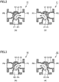
- first three-way valve 11 and second three-way valve 12 will be described with reference to Figs. 2 and 3 .
- first three-way valve 11 includes a first main body C1, a first flow path F1 and a first valve body V1.
- First main body C1 has first flow path F1 therein.
- First flow path F1 has a first connection port P1, and second and third connection ports P2 and P3 arranged so as to sandwich first connection port P1.
- First connection port P1 is connected to outlet 1b of compressor 1 shown in Fig. 1 .
- second connection port P2 is connected to outdoor heat exchanger (condenser) 3 shown in Fig. 1
- third connection port P3 is connected to indoor heat exchanger (evaporator) 5 shown in Fig. 1 .
- second connection port P2 is connected to indoor heat exchanger (condenser) 5 shown in Fig. 1
- third connection port P3 is connected to outdoor heat exchanger (evaporator) 3 shown in Fig. 1 .
- first valve body V1 is arranged in first flow path F1.
- First valve body V1 is configured to switch to connect first connection port P1 to one of second connection port P2 and third connection port P3.
- First valve body V1 is configured to be rotatable about an axial direction A of first valve body V1.
- First valve body V1 is, for example, an electrically-driven valve, and is configured such that driving thereof is controlled by a not-shown motor based on a command from controller 10.
- second three-way valve 12 includes a second main body C2, a second flow path F2 and a second valve body V2.
- Second main body C2 has second flow path F2 therein.
- Second flow path F2 has a fourth connection port P4, and fifth and sixth connection ports P5 and P6 arranged so as to sandwich fourth connection port P4.
- Fourth connection port P4 is connected to inlet 1a of compressor 1 shown in Fig. 1 .
- fifth connection port P5 is connected to indoor heat exchanger (evaporator) 5 shown in Fig. 1 .
- Sixth connection port P6 is connected to outdoor heat exchanger (condenser) 3 shown in Fig. 1 .
- fifth connection port P5 is connected to outdoor heat exchanger (evaporator) 3 shown in Fig. 1 .
- Sixth connection port P6 is connected to indoor heat exchanger (condenser) 5 shown in Fig. 1 .
- second valve body V2 is arranged in second flow path F2.
- Second valve body V2 is configured to switch to connect fourth connection port P4 to one of fifth connection port P5 and sixth connection port P6.
- Second valve body V2 is configured to be rotatable about axial direction A of second valve body V2.
- Second valve body V2 is, for example, an electrically-driven valve, and is configured such that driving thereof is controlled by a not-shown motor based on a command from controller 10.
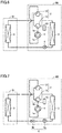
- first three-way valve 11 and second three-way valve 12 will be described with reference to Figs. 4 and 5 .
- first three-way valve 11 includes first main body C1, first flow path F1, first valve body V1, a first valve seat VS1, a second valve seat VS2, a rod RD, a movable body MB, a coil CO, and a spring SP.
- First main body C1 has first flow path F1 therein.
- First flow path F1 has first connection port P1, and second and third connection ports P2 and P3 arranged so as to sandwich first connection port P1.
- First connection port P1 is connected to outlet 1b of compressor 1 shown in Fig. 1 .
- second connection port P2 is connected to outdoor heat exchanger (condenser) 3 shown in Fig. 1
- third connection port P3 is connected to indoor heat exchanger (evaporator) 5 shown in Fig. 1 .
- second connection port P2 is connected to indoor heat exchanger (condenser) 5 shown in Fig. 1
- third connection port P3 is connected to outdoor heat exchanger (evaporator) 3 shown in Fig. 1 .
- First valve seat VS1 and second valve seat VS2 are arranged in first flow path F1.
- First valve seat VS1 is arranged between first connection port P1 and second connection port P2.
- Second valve seat VS2 is arranged between first connection port P1 and third connection port P3.
- First valve body V1 is connected to movable body MB by rod RD.
- Coil CO is arranged so as to surround movable body MB
- movable body MB is connected to spring SP.
- Spring SP is attached to each of movable body MB and first main body C1.
- first valve body V1 is arranged in first flow path F1.
- First valve body V1 is configured to switch to connect first connection port P1 to one of second connection port P2 and third connection port P3.
- Movable body MB is configured to be movable in an axial direction of rod RD due to a magnetic flux generated as a result of energization of coil CO based on a command from controller 10.
- Movable body MB is also configured to be movable in the axial direction of rod RD due to the elastic force of spring SP.
- first valve body V1 is configured to be movable in the axial direction of rod RD with the movement of movable body MB.
- first valve body V1 comes into contact with second valve seat VS2
- connection between first connection port P1 and third connection port P3 is interrupted, and first connection port P1 is connected to second connection port P2.
- first valve body V1 comes into contact with first valve seat VS1
- connection between first connection port P1 and second connection port P2 is interrupted, and first connection port P1 is connected to third connection port P3.
- second three-way valve 12 includes second main body C2, second flow path F2, second valve body V2, first valve seat VS1, second valve seat VS2, rod RD, the movable body, coil CO, and spring SP.
- Second main body C2 has second flow path F2 therein.
- Second flow path F2 has fourth connection port P4, and fifth and sixth connection ports P5 and P6 arranged so as to sandwich fourth connection port P4.
- Fourth connection port P4 is connected to inlet 1a of compressor 1 shown in Fig. 1 .
- fifth connection port P5 is connected to indoor heat exchanger (evaporator) 5 shown in Fig. 1 .
- Sixth connection port P6 is connected to outdoor heat exchanger (condenser) 3 shown in Fig. 1 .
- fifth connection port P5 is connected to outdoor heat exchanger (evaporator) 3 shown in Fig. 1 .
- Sixth connection port P6 is connected to indoor heat exchanger (condenser) 5 shown in Fig. 1 .
- First valve seat VS1 and second valve seat VS2 are arranged in second flow path F2.
- First valve seat VS1 is arranged between fourth connection port P4 and fifth connection port P5.
- Second valve seat VS2 is arranged between fourth connection port P4 and sixth connection port P6.
- Second valve body V2 is connected to movable body MB by rod RD.
- Coil CO is arranged so as to surround movable body MB
- movable body MB is connected to spring SP.
- Spring SP is attached to each of movable body MB and second main body C2.
- second valve body V2 is arranged in second flow path F1.
- Second valve body V2 is configured to switch to connect fourth connection port P4 to one of fifth connection port P5 and sixth connection port P6.
- Movable body MB is configured to be movable in an axial direction of rod RD due to a magnetic flux generated as a result of energization of coil CO based on a command from controller 10.
- Movable body MB is also configured to be movable in the axial direction of rod RD due to the elastic force of spring SP.
- second valve body V2 is configured to be movable in the axial direction of rod RD with the movement of movable body MB
- connection between fourth connection port P4 and sixth connection port P6 is interrupted, and fourth connection port P4 is connected to fifth connection port P5.
- connection between fourth connection port P4 and fifth connection port P5 is interrupted, and fourth connection port P4 is connected to sixth connection port P6.
- first three-way valve 11 is switched to the outdoor heat exchanger (condenser) 3 side
- second three-way valve 12 is switched to the indoor heat exchanger (evaporator) 5 side.
- first three-way valve 11 connects outlet 1b of compressor 1 to outdoor heat exchanger (condenser) 3, and second three-way valve 12 connects inlet 1a of compressor 1 to indoor heat exchanger (evaporator) 5. Furthermore, refrigerant expansion mechanism 4 is opened. That is, refrigerant expansion mechanism 4 operates so as to open the refrigerant circuit.
- the refrigerant flows through compressor 1 and first three-way valve 11, is condensed in outdoor heat exchanger (condenser) 3, is expanded in refrigerant expansion mechanism 4 to come into a low-pressure two-phase state, is evaporated in indoor heat exchanger (evaporator) 5, and flows through second three-way valve 12 to compressor 1 again. In this way, the refrigerant circulates through the refrigeration cycle apparatus.
- first three-way valve 11 is switched to the indoor heat exchanger (evaporator) 5 side, and at the same time, refrigerant expansion mechanism 4 is closed.
- Second three-way valve 12 remains switched to the indoor heat exchanger (evaporator) 5 side which is the same as during cooling operation.
- first three-way valve 11 connects outlet 1b of compressor 1 to indoor heat exchanger (evaporator) 5
- second three-way valve 12 connects inlet 1a of compressor 1 to indoor heat exchanger (evaporator) 5.
- refrigerant expansion mechanism 4 is closed. That is, refrigerant expansion mechanism 4 operates so as to close the refrigerant circuit.
- refrigerant leakage may occur when the electronic expansion valve is fully closed and it may take time to reach the fully closed state (generally, about 15 seconds).
- a capillary tube that does not have a closing mechanism may in some cases be used as refrigerant expansion mechanism 4.
- a shutoff valve may be provided so as to be closed during stop of the compressor.
- refrigerant expansion mechanism 4 includes a throttle device 4a and a shutoff valve 4b.
- Shutoff valve 4b is connected between throttle device 4a and outdoor heat exchanger (condenser or evaporator) 3 or between throttle device 4a and indoor heat exchanger (evaporator or condenser) 5.
- shutoff valve 4b is provided directly before or directly after throttle device 4a.
- first three-way valve 11 is switched to the indoor heat exchanger (condenser) 5 side
- second three-way valve 12 is switched to the outdoor heat exchanger (evaporator) 3 side.
- first three-way valve 11 connects outlet 1b of compressor 1 to indoor heat exchanger (condenser) 5
- second three-way valve 12 connects inlet 1a of compressor 1 to outdoor heat exchanger (evaporator) 3.
- refrigerant expansion mechanism 4 is opened. That is, refrigerant expansion mechanism 4 operates so as to open the refrigerant circuit.
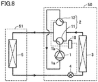
- the refrigerant flows through compressor 1 and first three-way valve 11, is condensed in indoor heat exchanger (condenser) 5, is expanded in refrigerant expansion mechanism 4 to come into a low-pressure two-phase state, is evaporated in outdoor heat exchanger (evaporator) 3, and flows through second three-way valve 12 to compressor 1 again. In this way, the refrigerant circulates through the refrigeration cycle apparatus.
- first three-way valve 11 is switched to the outdoor heat exchanger (evaporator) 3 side, and at the same time, refrigerant expansion mechanism 4 is closed.
- Second three-way valve 12 remains switched to the outdoor heat exchanger (evaporator) 3 side which is the same as during heating operation.
- first three-way valve 11 connects outlet 1b of compressor 1 to outdoor heat exchanger (evaporator) 3
- second three-way valve 12 connects inlet 1a of compressor 1 to outdoor heat exchanger (evaporator) 5.
- refrigerant expansion mechanism 4 is closed. That is, refrigerant expansion mechanism 4 operates so as to close the refrigerant circuit.
- the refrigerant is enclosed between cooling-heating switching mechanism 2 and refrigerant expansion mechanism 4 with indoor heat exchanger (condenser) 5 being interposed.
- indoor heat exchanger (condenser) 5 is interposed between refrigerant expansion mechanism 4 and cooling-heating switching mechanism 2.
- refrigerant leakage may also occur when the electronic expansion valve is fully closed and it may also take time to reach the fully closed state (generally, about 15 seconds) during stop of heating.
- a capillary tube that does not have a closing mechanism may in some cases be used as refrigerant expansion mechanism 4.
- a shutoff valve may be provided so as to be closed during stop of the compressor.
- refrigerant expansion mechanism 4 includes throttle device 4a and shutoff valve 4b.
- Shutoff valve 4b is connected between throttle device 4a and outdoor heat exchanger (condenser or evaporator) 3 or between throttle device 4a and indoor heat exchanger (evaporator or condenser) 5.
- shutoff valve 4b is provided directly before or directly after throttle device 4a.
- Fig. 11(A) shows a state in which the check valve is closed
- Fig. 11(B) shows a state in which the check valve is open.
- This small-sized check valve has a problem of production of a pressure loss during normal operation.
- Fig. 12(A) shows a state in which the check valve is closed
- Fig. 12(B) shows a state in which the check valve is open.
- this large-sized check valve has problems of high cost and an increase in amount of refrigerant leakage when the check valve is closed.
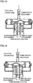
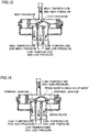
- Fig. 13 shows a flow of refrigerant during cooling operation.
- Fig. 14 shows a flow of the refrigerant during heating operation.
- Fig. 15 in the case of the sliding four-way valve, the high-temperature and high-pressure refrigerant discharged from a compressor and the low-temperature and low-pressure refrigerant introduced into the compressor flow in proximity to each other. Therefore, there is a problem of a cooling and heating capacity loss caused by heat exchange between the fluids in the four-way valve.
- Fig. 15 shows a cooling and heating capacity loss caused by heat exchange between the fluids in the four-way valve.
- the internal airtightness of the sliding four-way valve relies on pressing of a resin-made sliding valve body against a brass plate caused by a high-low pressure difference. Therefore, there is a problem of a reduction in cooling and heating capacity caused by leakage of the refrigerant from the high pressure side to the low pressure side.
- a high-pressure shell-type compressor is generally often used as compressor 1, and compressor 1 is gradually cooled to the outdoor air temperature when compressor 1 is stopped. At this time, the temperature of a lubricating oil in the compressor also decreases. As the oil temperature becomes lower, an amount of refrigerant dissolved in the oil becomes larger, and thus, a part of the refrigerant stored in outdoor heat exchanger (condenser) 3 flows into compressor 1. Therefore, a loss of the consumed power and the startup time at the restart of compressor 1 occurs.
- refrigerant expansion mechanism 4 closes the refrigerant circuit during stop of compressor 1, and thus, it is possible to prevent the high-temperature and high-pressure liquid refrigerant in the condenser (cooling operation: outdoor heat exchanger 3, heating operation: indoor heat exchanger 5) from flowing into the evaporator (cooling operation: indoor heat exchanger 5, heating operation: outdoor heat exchanger 3).
- First three-way valve 11 connects outlet 1b of compressor 1 to the evaporator (cooling operation: indoor heat exchanger 5, heating operation: outdoor heat exchanger 3), and second three-way valve 12 connects inlet 1a of compressor 1 to the evaporator (cooling operation: indoor heat exchanger 5, heating operation: outdoor heat exchanger 3).
- first three-way valve 11 and second three-way valve 12 can prevent the liquid refrigerant from flowing from the condenser (cooling operation: outdoor heat exchanger 3, heating operation: indoor heat exchanger 5) into compressor 1, and thus, a pressure loss during normal operation can be suppressed as compared with the case of using the check valve in the compressor discharge pipe.
- the three-way valve is of valve body type in Figs. 2 and 3 or of valve seat type in Figs. 4 and 5 , the three-way valve is structurally high in adhesion between the valve body and the valve seat. Therefore, the airtightness with respect to an internal high-low pressure difference is high as compared with the sliding four-way valve which is a common cooling-heating switching mechanism as in Comparative Example 2. Therefore, a cooling capacity loss caused by internal leakage of the refrigerant can be reduced.
- the three-way valve in Figs. 2 and 3 and the three-way valve in Figs. 4 and 5 are higher in airtightness than the check valve in Comparative Example 1 and the sliding four-way valve in Comparative Example 2, and thus, an amount of refrigerant leaking inside until restart can be reduced. Therefore, a loss of heat and power related to restart can be reduced.
- the first three-way valve switches to connect the first connection port to one of the second connection port and the third connection port by the first valve body.
- the second three-way valve switches to connect the fourth connection port to one of the fifth connection port and the sixth connection port by the second valve body.
- refrigerant expansion mechanism 4 includes the electronic expansion valve. Therefore, the refrigerant circuit can be opened and closed by the electronic expansion valve with a high degree of precision.
- refrigerant expansion mechanism 4 includes throttle device 4a and shutoff valve 4b. Therefore, the refrigerant circuit can be reliably closed by shutoff valve 4b. In addition, the time required to reach the fully closed state can be reduced. Furthermore, a capillary tube that does not have a closing mechanism can, for example, be used as throttle device 4a.
- cooling-heating switching mechanism 2 includes a five-way valve.
- the five-way valve is configured to switch to connect outlet 1b of compressor 1 to one of the condenser (cooling operation: outdoor heat exchanger 3, heating operation: indoor heat exchanger 5) and the evaporator (cooling operation: indoor heat exchanger 5, heating operation: outdoor heat exchanger 3).
- the five-way valve is also configured to switch to connect inlet 1a of compressor 1 to one of the condenser (cooling operation: outdoor heat exchanger 3, heating operation: indoor heat exchanger 5) and the evaporator (cooling operation: indoor heat exchanger 5, heating operation: outdoor heat exchanger 3).
- the five-way valve is configured to open and close the refrigerant circuit connected to one of outlet 1b and inlet 1a of compressor 1.
- the five-way valve is configured to open and close the refrigerant circuit connected to inlet 1a of compressor 1.
- the five-way valve is configured to connect outlet 1b of compressor 1 to the condenser (cooling operation: outdoor heat exchanger 3, heating operation: indoor heat exchanger 5), and is configured to connect inlet 1a of compressor 1 to the evaporator (cooling operation: indoor heat exchanger 5, heating operation: outdoor heat exchanger 3).
- the five-way valve is configured to connect one of outlet 1b and inlet 1a of compressor 1 to the evaporator (cooling operation: indoor heat exchanger 5, heating operation: outdoor heat exchanger 3), and is configured to close the refrigerant circuit connected to the other of outlet 1b and inlet 1a of compressor 1.
- the five-way valve is configured to close the refrigerant circuit connected to inlet 1a of compressor 1.
- refrigerant expansion mechanism 4 is configured to open the refrigerant circuit during operation of compressor 1 and close the refrigerant circuit during stop of compressor 1.
- the five-way valve has five connection ports. Two of these five connection ports are connected to the compressor suction pipe, and the remaining three connection ports are connected to the compressor discharge pipe, outdoor heat exchanger 3 and indoor heat exchanger 5, respectively.
- the refrigerant flows similarly from either of the two connection ports connected to the compressor suction pipe.
- the five-way valve in the present embodiment is a rotary five-way valve.
- the five-way valve includes a case CA and a valve VA.
- Case CA has a circular internal space IS, and first connection port P1, second connection port P2, third connection port P3, fourth connection port P4, and fifth connection port P5 communicating with internal space IS.
- Each of first connection port P1, second connection port P2, third connection port P3, fourth connection port P4, and fifth connection port P5 is provided in a bottom surface of case CA.
- Valve VA is arranged in internal space IS of case CA.
- Valve VA has a cylindrical shape.
- Valve VA is configured to be rotatable about axial direction A.
- Valve VA has a first internal flow path IF1 and a second internal flow path IF2.
- First internal flow path IF1 is configured to allow two of first connection port P1, second connection port P2, third connection port P3, fourth connection port P4, and fifth connection port P5 to communicate with each other.
- Second internal flow path IF2 is configured to allow the other two connection ports to communicate with each other.
- Each of first internal flow path IF1 and second internal flow path IF2 is configured to extend from the bottom surface toward a top surface of valve VA and then be folded back to the bottom surface.
- Valve VA is configured to rotate about the axial direction, thereby switching to allow two of first connection port P1, second connection port P2, third connection port P3, fourth connection port P4, and fifth connection port P5 to selectively communicate with each other by each of first internal flow path IF1 and second internal flow path IF2, and close the remaining one connection port.
- first connection port P1 is connected to outlet 1b of compressor 1.
- Second connection port P2 is connected to one of the condenser (cooling operation: outdoor heat exchanger 3, heating operation: indoor heat exchanger 5) and the evaporator (cooling operation: indoor heat exchanger 5, heating operation: outdoor heat exchanger 3).
- Third connection port P3 is connected to the other of the condenser (cooling operation: outdoor heat exchanger 3, heating operation: indoor heat exchanger 5) and the evaporator (cooling operation: indoor heat exchanger 5, heating operation: outdoor heat exchanger 3).
- Fourth connection port P4 and fifth connection port P5 are connected to inlet 1a of compressor 1.
- the five-way valve connects outlet 1b of compressor 1 to outdoor heat exchanger (condenser) 3 and connects inlet 1a of compressor 1 to indoor heat exchanger (evaporator) 5. Furthermore, refrigerant expansion mechanism 4 is opened. That is, refrigerant expansion mechanism 4 operates so as to open the refrigerant circuit.
- the refrigerant flows through compressor 1 and cooling-heating switching mechanism 2, is condensed in outdoor heat exchanger (condenser) 3, is expanded in refrigerant expansion mechanism 4 to come into a low-pressure two-phase state, is evaporated in indoor heat exchanger (evaporator) 5, and flows through cooling-heating switching mechanism 2 to compressor 1 again. In this way, the refrigerant circulates through the refrigeration cycle apparatus.
- Fig. 22 the five-way valve is switched as shown in Fig. 22 , and thus, the compressor discharge pipe and indoor heat exchanger (evaporator) 5 are connected and the compressor suction pipes are connected. At the same time, refrigerant expansion mechanism 4 is closed.
- the five-way valve connects outlet 1b of compressor 1 to indoor heat exchanger (evaporator) 5 and closes the refrigerant circuit connected to inlet 1a of compressor 1. Furthermore, refrigerant expansion mechanism 4 is closed. That is, refrigerant expansion mechanism 4 operates so as to close the refrigerant circuit.
- refrigerant expansion mechanism 4 includes throttle device 4a and shutoff valve 4b in the modification of refrigerant expansion mechanism 4 during stop of cooling.
- Fig. 24 the five-way valve is switched as shown in Fig. 24 , and thus, the compressor discharge pipe and indoor heat exchanger (condenser) 5 are connected and the compressor suction pipe and outdoor heat exchanger (evaporator) 3 are connected.
- the five-way valve connects outlet 1b of compressor 1 to indoor heat exchanger (condenser) 5 and connects inlet 1a of compressor 1 to outdoor heat exchanger (evaporator) 3. Furthermore, refrigerant expansion mechanism 4 is opened. That is, refrigerant expansion mechanism 4 operates so as to open the refrigerant circuit.
- the refrigerant flows through compressor 1 and cooling-heating switching mechanism 2, is condensed in indoor heat exchanger (condenser) 5, is expanded in refrigerant expansion mechanism 4 to come into a low-pressure two-phase state, is evaporated in outdoor heat exchanger (evaporator) 3, and flows through cooling-heating switching mechanism 2 to compressor 1 again. In this way, the refrigerant circulates through the refrigeration cycle apparatus.
- Fig. 25 the five-way valve is switched as shown in Fig. 25 , and thus, the compressor discharge pipe and outdoor heat exchanger (evaporator) 3 are connected and the compressor suction pipes are connected. At the same time, refrigerant expansion mechanism 4 is closed.
- the five-way valve connects outlet 1b of compressor 1 to outdoor heat exchanger (evaporator) 3 and closes the refrigerant circuit connected to inlet 1a of compressor 1. Furthermore, refrigerant expansion mechanism 4 is closed. That is, refrigerant expansion mechanism 4 operates so as to close the refrigerant circuit.
- the refrigerant is enclosed between cooling-heating switching mechanism 2 and refrigerant expansion mechanism 4 with indoor heat exchanger (condenser) 5 being interposed.
- indoor heat exchanger (condenser) 5 is interposed between refrigerant expansion mechanism 4 and cooling-heating switching mechanism 2.
- refrigerant expansion mechanism 4 includes throttle device 4a and shutoff valve 4b in the modification of refrigerant expansion mechanism 4 during stop of heating.
- refrigerant expansion mechanism 4 closes the refrigerant circuit during stop of compressor 1, and thus, it is possible to prevent the high-temperature and high-pressure liquid refrigerant in the condenser (cooling operation: outdoor heat exchanger 3, heating operation: indoor heat exchanger 5) from flowing into the evaporator (cooling operation: indoor heat exchanger 5, heating operation: outdoor heat exchanger 3).
- the five-way valve connects one of outlet 1b and inlet 1a of compressor 1 to the evaporator (cooling operation: indoor heat exchanger 5, heating operation: outdoor heat exchanger 3), and closes the refrigerant circuit connected to the other of outlet 1b and inlet 1a of compressor 1.
- the five-way valve can prevent the liquid refrigerant from flowing from the condenser (cooling operation: outdoor heat exchanger 3, heating operation: indoor heat exchanger 5) into compressor 1, and thus, a pressure loss during normal operation can be suppressed as compared with the case of using the check valve in the compressor discharge pipe.
- the rotary valve is higher in airtightness than the above-described check valve and the above-described sliding four-way valve. Therefore, both during operation of the compressor and during stop of the compressor, a cooling and heating capacity loss caused by internal leakage of the refrigerant and a cooling and heating restart loss can be reduced.
- fourth connection port P4 and fifth connection port P5 are connected to inlet 1a of compressor 1. Therefore, the refrigerant circuit can be closed by connecting fourth connection port P4 and fifth connection port P5.
- Fig. 27 is a refrigerant circuit diagram of the refrigeration cycle apparatus in the third embodiment of the present invention.
- the five-way valve is configured to open and close the refrigerant circuit connected to outlet 1b of compressor 1.
- connection ports of the five-way valve are connected to the compressor discharge pipe, and the remaining three connection ports are connected to the compressor suction pipe, outdoor heat exchanger 3 and indoor heat exchanger 5, respectively.
- the refrigerant similarly flows from either of the two connection ports connected to the compressor discharge pipe.
- first connection port P1 and second connection port P2 are connected to outlet 1b of compressor 1.
- Third connection port P3 is connected to inlet 1a of compressor 1.
- Fourth connection port P4 is connected to one of the condenser (cooling operation: outdoor heat exchanger 3, heating operation: indoor heat exchanger 5) and the evaporator (cooling operation: indoor heat exchanger 5, heating operation: outdoor heat exchanger 3).
- Fifth connection port P5 is connected to the other of the condenser (cooling operation: outdoor heat exchanger 3, heating operation: indoor heat exchanger 5) and the evaporator (cooling operation: indoor heat exchanger 5, heating operation: outdoor heat exchanger 3).
- Fig. 27 The operation during cooling operation will be described with reference again to Fig. 27 .
- the five-way valve is switched as shown in Fig. 27 , and thus, the compressor discharge pipe and outdoor heat exchanger (condenser) 3 are connected and the compressor suction pipe and indoor heat exchanger (evaporator) 5 are connected.
- the five-way valve connects outlet 1b of compressor 1 to outdoor heat exchanger (condenser) 3 and connects inlet 1a of compressor 1 to indoor heat exchanger (evaporator) 5. Furthermore, refrigerant expansion mechanism 4 is opened. That is, refrigerant expansion mechanism 4 operates so as to open the refrigerant circuit.
- the refrigerant flows through compressor 1 and cooling-heating switching mechanism 2, is condensed in outdoor heat exchanger (condenser) 3, is expanded in refrigerant expansion mechanism 4 to come into a low-pressure two-phase state, is evaporated in indoor heat exchanger (evaporator) 5, and flows through cooling-heating switching mechanism 2 to compressor 1 again. In this way, the refrigerant circulates through the refrigeration cycle apparatus.
- Fig. 28 the five-way valve is switched as shown in Fig. 28 , and thus, the compressor suction pipe and indoor heat exchanger (evaporator) 5 are connected and the compressor discharge pipes are connected. At the same time, refrigerant expansion mechanism 4 is closed.
- the five-way valve connects inlet 1a of compressor 1 to indoor heat exchanger (evaporator) 5 and closes the refrigerant circuit connected to outlet 1b of compressor 1. Furthermore, refrigerant expansion mechanism 4 is closed. That is, refrigerant expansion mechanism 4 operates so as to close the refrigerant circuit.
- Fig. 29 the five-way valve is switched as shown in Fig. 29 , and thus, the compressor discharge pipe and indoor heat exchanger (condenser) 5 are connected and the compressor suction pipe and outdoor heat exchanger (evaporator) 3 are connected.
- the five-way valve connects outlet 1b of compressor 1 to indoor heat exchanger (condenser) 5 and connects inlet 1a of compressor 1 to outdoor heat exchanger (evaporator) 3. Furthermore, refrigerant expansion mechanism 4 is opened. That is, refrigerant expansion mechanism 4 operates so as to open the refrigerant circuit.
- the refrigerant flows through compressor 1 and cooling-heating switching mechanism 2, is condensed in indoor heat exchanger (condenser) 5, is expanded in refrigerant expansion mechanism 4 to come into a low-pressure two-phase state, is evaporated in outdoor heat exchanger (evaporator) 3, and flows through cooling-heating switching mechanism 2 to compressor 1 again. In this way, the refrigerant circulates through the refrigeration cycle apparatus.
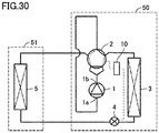
- Fig. 30 the five-way valve is switched as shown in Fig. 30 , and thus, the compressor suction pipe and outdoor heat exchanger (evaporator) 3 are connected and the compressor discharge pipes are connected. At the same time, refrigerant expansion mechanism 4 is closed.
- the five-way valve connects inlet 1a of compressor 1 to outdoor heat exchanger (evaporator) 3 and closes the refrigerant circuit connected to outlet 1b of compressor 1. Furthermore, refrigerant expansion mechanism 4 is closed. That is, refrigerant expansion mechanism 4 operates so as to close the refrigerant circuit.
- the refrigerant is enclosed between cooling-heating switching mechanism 2 and refrigerant expansion mechanism 4 with indoor heat exchanger (condenser) 5 being interposed.
- indoor heat exchanger (condenser) 5 is interposed between refrigerant expansion mechanism 4 and cooling-heating switching mechanism 2.
- the five-way valve is switched as described above during stop of cooling and during stop of heating, and thus, the high-temperature and high-pressure liquid refrigerant can be enclosed in the heat exchanger on the condenser side during stop of the compressor.
- equalization of the high pressure and the low pressure during stop of the compressor can be prevented, and thus, the restart power of the compressor can be reduced.
- the time required to re-form the high pressure and the low pressure is unnecessary, and thus, the startup time of the cooling and heating capacity can be reduced.
- the compressor suction pipe occupies the two connection ports in the second embodiment, while the compressor discharge pipe occupies the two connection ports in the third embodiment. Since the density of the refrigerant is lower in the case of the low pressure than in the case of the high pressure, a pressure loss increases unless a pipe diameter is large. Therefore, the compressor discharge pipe is connected to the two connection ports in the third embodiment, and thus, the five-way valve can be reduced in size.
- first connection port P1 and second connection port P2 are connected to outlet 1b of compressor 1. Therefore, the refrigerant circuit can be closed by connecting fourth connection port P4 and fifth connection port P5.
Landscapes
- Engineering & Computer Science (AREA)
- Physics & Mathematics (AREA)
- Mechanical Engineering (AREA)
- Thermal Sciences (AREA)
- General Engineering & Computer Science (AREA)
- Compression-Type Refrigeration Machines With Reversible Cycles (AREA)
Abstract
Description
- The present invention relates to a refrigeration cycle apparatus.
- A refrigeration cycle apparatus including a constant-speed compressor performs the start-stop operation (operation of repeating start and stop) when a thermal load is low. When the compressor is stopped, high-temperature and high-pressure liquid refrigerant stored in a condenser flows into an evaporator on the low-temperature and low-pressure side. As a result, the evaporator is heated by and filled with this liquid refrigerant.
- At the restart of the refrigeration cycle apparatus, it is necessary to move the liquid refrigerant stored on the evaporator side to the condenser side again by the work of the compressor. Therefore, there are problems of a delay in cooling and heating restart time and an increase in consumed power in the compressor.
- Also in the case of a refrigeration cycle apparatus including an inverter compressor whose driving frequency can be controlled, when the frequency of the compressor reaches the lowest frequency for control, the inverter compressor cannot operate with the capacity equal to or lower than the lowest frequency. Therefore, the refrigeration cycle apparatus including the inverter compressor also performs the start-stop operation. Accordingly, similarly to the refrigeration cycle apparatus including the constant-speed compressor, there are problems of a delay in cooling and heating restart time and an increase in consumed power in the compressor.
- PTD 1 (Japanese Patent Publication No.
63-46350 - PTD 1: Japanese Patent Publication No.
63-46350 - However, the air conditioner described in the above-referenced patent document includes the check valve placed in the compressor discharge pipe, and thus, has a problem of a pressure loss during normal operation caused by the check valve.
- The present invention has been made in light of the above-described problem, and an object of the present invention is to provide a refrigeration cycle apparatus in which the cooling and heating restart time can be reduced, the consumed power in a compressor can be reduced and a pressure loss during normal operation can be suppressed.
- A refrigeration cycle apparatus of the present invention includes: a refrigerant circuit; and refrigerant. The refrigerant circuit has a compressor, a cooling-heating switching mechanism, a condenser, a refrigerant expansion mechanism, and an evaporator. The refrigerant circulates through the refrigerant circuit in order of the compressor, the cooling-heating switching mechanism, the condenser, the refrigerant expansion mechanism, the evaporator, and the cooling-heating switching mechanism. The compressor has an inlet and an outlet, and is configured to compress the refrigerant introduced from the inlet and discharge the refrigerant from the outlet. The refrigerant expansion mechanism is configured to open and close the refrigerant circuit. The cooling-heating switching mechanism has a first three-way valve configured to switch to connect the outlet of the compressor to one of the condenser and the evaporator, and a second three-way valve configured to switch to connect the inlet of the compressor to one of the condenser and the evaporator. During operation of the compressor, the refrigerant expansion mechanism opens the refrigerant circuit, the first three-way valve connects the outlet of the compressor to the condenser, and the second three-way valve connects the inlet of the compressor to the evaporator. During stop of the compressor, the refrigerant expansion mechanism closes the refrigerant circuit, the first three-way valve connects the outlet of the compressor to the evaporator, and the second three-way valve connects the inlet of the compressor to the evaporator.
- According to the refrigeration cycle apparatus of the present invention, the refrigerant expansion mechanism closes the refrigerant circuit during stop of the compressor, and thus, it is possible to prevent the high-temperature and high-pressure liquid refrigerant in the condenser from flowing into the evaporator. The first three-way valve connects the outlet of the compressor to the evaporator, and the second three-way valve connects the inlet of the compressor to the evaporator. Therefore, it is possible to prevent the high-temperature and high-pressure liquid refrigerant and the refrigerant gas in the condenser from flowing into the compressor. Therefore, the high-temperature and high-pressure liquid refrigerant in the condenser can be stored between the refrigerant expansion mechanism and the cooling-heating switching mechanism with the condenser being interposed. Therefore, it is unnecessary to move the liquid refrigerant flowing from the condenser into the evaporator and the compressor during stop of the compressor, from the evaporator and the compressor to the condenser at the restart of the compressor. Therefore, the cooling and heating restart time can be reduced and the consumed power in the compressor can be reduced. In addition, the first three-way valve and the second three-way valve can prevent the liquid refrigerant from flowing from the condenser into the compressor, and thus, a pressure loss during normal operation can be suppressed.
-
-
Fig. 1 is a refrigerant circuit diagram of a refrigeration cycle apparatus in a first embodiment of the present invention. -
Fig. 2 is a cross-sectional view schematically showing a configuration of one example of a first three-way valve in the first embodiment of the present invention. -
Fig. 3 is a cross-sectional view schematically showing a configuration of one example of a second three-way valve in the first embodiment of the present invention. -
Fig. 4 is a cross-sectional view schematically showing a configuration of another example of the first three-way valve in the first embodiment of the present invention. -
Fig. 5 is a cross-sectional view schematically showing a configuration of another example of the second three-way valve in the first embodiment of the present invention. -
Fig. 6 is a refrigerant circuit diagram during stop of cooling in the first embodiment of the present invention. -
Fig. 7 is a refrigerant circuit diagram of a modification of a refrigerant expansion mechanism during stop of cooling in the first embodiment of the present invention. -
Fig. 8 is a refrigerant circuit diagram during heating operation in the first embodiment of the present invention. -
Fig. 9 is a refrigerant circuit diagram during stop of heating in the first embodiment of the present invention. -
Fig. 10 is a refrigerant circuit diagram of the modification of the refrigerant expansion mechanism during stop of heating in the first embodiment of the present invention. -
Fig. 11 is a cross-sectional view schematically showing a configuration of a small-sized check valve in Comparative Example 1. -
Fig. 12 is a cross-sectional view schematically showing a configuration of a large-sized check valve in Comparative Example 2. -
Fig. 13 is a cross-sectional view schematically showing a configuration of a sliding four-way valve and a flow of refrigerant during cooling operation in Comparative Example 3. -
Fig. 14 is a cross-sectional view schematically showing a configuration of the sliding four-way valve and a flow of the refrigerant during heating operation in Comparative Example 3. -
Fig. 15 is a cross-sectional view schematically showing heat exchange in the sliding four-way valve in Comparative Example 3. -
Fig. 16 is a cross-sectional view schematically showing refrigerant leakage in the sliding four-way valve in Comparative Example 3. -
Fig. 17 is a refrigerant circuit diagram during stop of cooling in Comparative Example 4. -
Fig. 18 is a refrigerant circuit diagram during stop of heating in Comparative Example 4. -
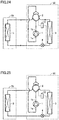
Fig. 19 is a refrigerant circuit diagram of a refrigeration cycle apparatus in a second embodiment of the present invention. -
Fig. 20 is a perspective view schematically showing a configuration of a five-way valve in the second embodiment of the present invention. -
Fig. 21 is a perspective view showing a state in which the five-way valve shown inFig. 20 has rotated and a first internal flow path and a second internal flow path have been switched. -
Fig. 22 is a refrigerant circuit diagram during stop of cooling in the second embodiment of the present invention. -
Fig. 23 is a refrigerant circuit diagram of a modification of a refrigerant expansion mechanism during stop of cooling in the second embodiment of the present invention. -
Fig. 24 is a refrigerant circuit diagram during heating operation in the second embodiment of the present invention. -
Fig. 25 is a refrigerant circuit diagram during stop of heating in the second embodiment of the present invention. -
Fig. 26 is a refrigerant circuit diagram of the modification of the refrigerant expansion mechanism during stop of heating in the second embodiment of the present invention. -
Fig. 27 is a refrigerant circuit diagram of a refrigeration cycle apparatus in a third embodiment of the present invention. -
Fig. 28 is a refrigerant circuit diagram during stop of cooling in the third embodiment of the present invention. -
Fig. 29 is a refrigerant circuit diagram during heating operation in the third embodiment of the present invention. -
Fig. 30 is a refrigerant circuit diagram during stop of heating in the third embodiment of the present invention. - Embodiments of the present invention will be described hereinafter with reference to the drawings.
-
Fig. 1 is a refrigerant circuit diagram of a refrigeration cycle apparatus in a first embodiment of the present invention. A configuration of the refrigeration cycle apparatus in the first embodiment of the present invention will be described with reference toFig. 1 . - The refrigeration cycle apparatus in the first embodiment of the present invention includes a refrigerant circuit having a
compressor 1, a cooling-heating switching mechanism 2, anoutdoor heat exchanger 3, arefrigerant expansion mechanism 4, and anindoor heat exchanger 5. The refrigeration cycle apparatus in the first embodiment of the present invention also includes acontroller 10.Compressor 1, cooling-heating switching mechanism 2,outdoor heat exchanger 3,refrigerant expansion mechanism 4, andindoor heat exchanger 5 communicate with one another by a pipe to thereby form the refrigerant circuit.Compressor 1, cooling-heating switching mechanism 2,outdoor heat exchanger 3, andrefrigerant expansion mechanism 4 are housed in anoutdoor unit 50.Indoor heat exchanger 5 is housed in anindoor unit 51. - The refrigeration cycle apparatus in the first embodiment of the present invention also includes refrigerant circulating through the refrigerant circuit. R410a, R32, R1234yf and the like can, for example, be used as the refrigerant.
- During cooling operation, the refrigerant circulates through the refrigerant circuit in order of
compressor 1, cooling-heating switching mechanism 2, outdoor heat exchanger (condenser) 3,refrigerant expansion mechanism 4, indoor heat exchanger (evaporator) 5, and cooling-heating switching mechanism 2. That is, the refrigerant circuit is configured such that the refrigerant having flown throughcompressor 1, cooling-heating switching mechanism 2, outdoor heat exchanger (condenser) 3,refrigerant expansion mechanism 4, and indoor heat exchanger (evaporator) 5 in this order passes through cooling-heating switching mechanism 2 again and reachescompressor 1. - On the other hand, during heating operation, the refrigerant circulates through the refrigerant circuit in order of
compressor 1, cooling-heating switching mechanism 2, indoor heat exchanger (condenser) 5,refrigerant expansion mechanism 4, outdoor heat exchanger (evaporator) 3, and cooling-heating switching mechanism 2. That is, the refrigerant circuit is configured such that the refrigerant having flown throughcompressor 1, cooling-heating switching mechanism 2, indoor heat exchanger (condenser) 5,refrigerant expansion mechanism 4, and outdoor heat exchanger (evaporator) 3 in this order passes through cooling-heating switching mechanism 2 again and reachescompressor 1. -
Compressor 1 is configured to compress the refrigerant.Compressor 1 has aninlet 1a and anoutlet 1b.Compressor 1 is configured to compress the refrigerant introduced frominlet 1a and discharge the refrigerant fromoutlet 1b.Compressor 1 may be a constant-speed compressor having a constant compression capacity, or may be an inverter compressor having a variable compression capacity. The inverter compressor is configured such that the number of rotations can be variably controlled. Specifically, the driving frequency of the inverter compressor is changed based on a command fromcontroller 10 and the number of rotations is thereby adjusted. As a result, the compression capacity varies. The compression capacity refers to an amount of refrigerant delivered per unit time. - Cooling-
heating switching mechanism 2 is configured to switch a flow of the refrigerant between during cooling operation and during heating operation. Cooling-heating switching mechanism 2 includes a first three-way valve 11 and a second three-way valve 12. First three-way valve 11 and second three-way valve 12 are configured to be switchable independently from each other. First three-way valve 11 and second three-way valve 12 are connected to each other by a pipe. - First three-
way valve 11 is configured to switch to connectoutlet 1b ofcompressor 1 to one of outdoor heat exchanger (cooling operation: condenser, heating operation: evaporator) 3 and indoor heat exchanger (cooling operation: evaporator, heating operation: condenser) 5. First three-way valve 11 is connected tooutlet 1b ofcompressor 1 by a pipe (compressor discharge pipe). First three-way valve 11 is connected to each ofoutdoor heat exchanger 3 andindoor heat exchanger 5 by a pipe. - Second three-
way valve 12 is configured to switch to connectinlet 1a ofcompressor 1 to one of outdoor heat exchanger (cooling operation: condenser, heating operation: evaporator) 3 and indoor heat exchanger (cooling operation: evaporator, heating operation: condenser) 5. Second three-way valve 12 is connected toinlet 1a ofcompressor 1 by a pipe (compressor suction pipe). Second three-way valve 12 is connected to each ofoutdoor heat exchanger 3 andindoor heat exchanger 5 by a pipe. - During operation of
compressor 1, first three-way valve 11 is configured to connectoutlet 1b ofcompressor 1 to the condenser (cooling operation:outdoor heat exchanger 3, heating operation: indoor heat exchanger 5), and second three-way valve 12 is configured to connectinlet 1a ofcompressor 1 to the evaporator (cooling operation:indoor heat exchanger 5, heating operation: outdoor heat exchanger 3). During stop ofcompressor 1, first three-way valve 11 is configured to connectoutlet 1b ofcompressor 1 to the evaporator (cooling operation:indoor heat exchanger 5, heating operation: outdoor heat exchanger 3), and second three-way valve 12 is configured to connectinlet 1a ofcompressor 1 to the evaporator (cooling operation:indoor heat exchanger 5, heating operation: outdoor heat exchanger 3). -
Outdoor heat exchanger 3 is for performing heat exchange between the refrigerant and the air (outdoor air).Outdoor heat exchanger 3 is formed, for example, by a pipe and a fin. During cooling operation,outdoor heat exchanger 3 functions as a condenser, and performs heat exchange between the air and the refrigerant introduced via cooling-heating switching mechanism 2 and compressed bycompressor 1, to thereby condense and liquefy the refrigerant. That is, during cooling operation, outdoor heat exchanger (condenser) 3 is configured to condense the refrigerant compressed bycompressor 1. - On the other hand, during heating operation,
outdoor heat exchanger 3 functions as an evaporator, and performs heat exchange between the air and the low-pressure refrigerant introduced viarefrigerant expansion mechanism 4, to thereby evaporate and vaporize the refrigerant. That is, during heating operation, outdoor heat exchanger (evaporator) 3 is configured to evaporate the refrigerant expanded (decompressed) byrefrigerant expansion mechanism 4. -
Refrigerant expansion mechanism 4 is configured to expand (decompress) the refrigerant condensed by the condenser (cooling operation:outdoor heat exchanger 3, heating operation: indoor heat exchanger 5).Refrigerant expansion mechanism 4 is configured to open and close the refrigerant circuit.Refrigerant expansion mechanism 4 is configured to open the refrigerant circuit during operation ofcompressor 1 and close the refrigerant circuit during stop ofcompressor 1.Refrigerant expansion mechanism 4 includes, for example, an electronic expansion valve. In this case,refrigerant expansion mechanism 4 is configured to be capable of adjusting a flow rate of the refrigerant flowing throughrefrigerant expansion mechanism 4, by adjusting the degree of opening of the electronic expansion valve. The flow rate of the refrigerant flowing throughrefrigerant expansion mechanism 4 refers to a flow rate per unit time. -
Indoor heat exchanger 5 is for performing heat exchange between the refrigerant and the air (indoor air).Indoor heat exchanger 5 is formed, for example, by a pipe and a fin. During cooling operation,indoor heat exchanger 5 functions as an evaporator, and performs heat exchange between the air and the refrigerant brought into the low-pressure state byrefrigerant expansion mechanism 4, and causes the refrigerant to take away the heat of the air, to thereby evaporate and vaporize the refrigerant. That is, indoor heat exchanger (evaporator) 5 is configured to evaporate the refrigerant expanded (decompressed) byrefrigerant expansion mechanism 4. - On the other hand, during heating operation,
indoor heat exchanger 5 functions as a condenser, and performs heat exchange between the air and the refrigerant introduced via cooling-heating switching mechanism 2 and compressed bycompressor 1, to thereby condense and liquefy the refrigerant. That is, during heating operation, indoor heat exchanger (condenser) 5 is configured to condense the refrigerant compressed bycompressor 1. -
Controller 10 is configured to control the means, the devices and the like of the refrigeration apparatus by, for example, performing a computation and providing a command. Particularly,controller 10 is configured to control the operation of cooling-heating switching mechanism 2 andrefrigerant expansion mechanism 4. Specifically,controller 10 is electrically connected to each of first and second three-way valves refrigerant expansion mechanism 4, and is configured to control the operation of these components. - One example of each of first three-
way valve 11 and second three-way valve 12 will be described with reference toFigs. 2 and 3 . - As shown in
Fig. 2(A) , first three-way valve 11 includes a first main body C1, a first flow path F1 and a first valve body V1. First main body C1 has first flow path F1 therein. First flow path F1 has a first connection port P1, and second and third connection ports P2 and P3 arranged so as to sandwich first connection port P1. - First connection port P1 is connected to
outlet 1b ofcompressor 1 shown inFig. 1 . During cooling operation, second connection port P2 is connected to outdoor heat exchanger (condenser) 3 shown inFig. 1 , and third connection port P3 is connected to indoor heat exchanger (evaporator) 5 shown inFig. 1 . On the other hand, during heating operation, second connection port P2 is connected to indoor heat exchanger (condenser) 5 shown inFig. 1 , and third connection port P3 is connected to outdoor heat exchanger (evaporator) 3 shown inFig. 1 . - As shown in
Figs. 2(A) and 2(B) , first valve body V1 is arranged in first flow path F1. First valve body V1 is configured to switch to connect first connection port P1 to one of second connection port P2 and third connection port P3. First valve body V1 is configured to be rotatable about an axial direction A of first valve body V1. First valve body V1 is, for example, an electrically-driven valve, and is configured such that driving thereof is controlled by a not-shown motor based on a command fromcontroller 10. - As shown in
Fig. 3(A) , second three-way valve 12 includes a second main body C2, a second flow path F2 and a second valve body V2. Second main body C2 has second flow path F2 therein. Second flow path F2 has a fourth connection port P4, and fifth and sixth connection ports P5 and P6 arranged so as to sandwich fourth connection port P4. - Fourth connection port P4 is connected to
inlet 1a ofcompressor 1 shown inFig. 1 . During cooling operation, fifth connection port P5 is connected to indoor heat exchanger (evaporator) 5 shown inFig. 1 . Sixth connection port P6 is connected to outdoor heat exchanger (condenser) 3 shown inFig. 1 . On the other hand, during heating operation, fifth connection port P5 is connected to outdoor heat exchanger (evaporator) 3 shown inFig. 1 . Sixth connection port P6 is connected to indoor heat exchanger (condenser) 5 shown inFig. 1 . - As shown in
Figs. 3(A) and 3(B) , second valve body V2 is arranged in second flow path F2. Second valve body V2 is configured to switch to connect fourth connection port P4 to one of fifth connection port P5 and sixth connection port P6. Second valve body V2 is configured to be rotatable about axial direction A of second valve body V2. Second valve body V2 is, for example, an electrically-driven valve, and is configured such that driving thereof is controlled by a not-shown motor based on a command fromcontroller 10. - Next, another example of each of first three-
way valve 11 and second three-way valve 12 will be described with reference toFigs. 4 and5 . - As shown in
Fig. 4(A) , first three-way valve 11 includes first main body C1, first flow path F1, first valve body V1, a first valve seat VS1, a second valve seat VS2, a rod RD, a movable body MB, a coil CO, and a spring SP. First main body C1 has first flow path F1 therein. First flow path F1 has first connection port P1, and second and third connection ports P2 and P3 arranged so as to sandwich first connection port P1. - First connection port P1 is connected to
outlet 1b ofcompressor 1 shown inFig. 1 . During cooling operation, second connection port P2 is connected to outdoor heat exchanger (condenser) 3 shown inFig. 1 , and third connection port P3 is connected to indoor heat exchanger (evaporator) 5 shown inFig. 1 . On the other hand, during heating operation, second connection port P2 is connected to indoor heat exchanger (condenser) 5 shown inFig. 1 , and third connection port P3 is connected to outdoor heat exchanger (evaporator) 3 shown inFig. 1 . - First valve seat VS1 and second valve seat VS2 are arranged in first flow path F1. First valve seat VS1 is arranged between first connection port P1 and second connection port P2. Second valve seat VS2 is arranged between first connection port P1 and third connection port P3.
- First valve body V1 is connected to movable body MB by rod RD. Coil CO is arranged so as to surround movable body MB On the opposite side of rod RD, movable body MB is connected to spring SP. Spring SP is attached to each of movable body MB and first main body C1.
- As shown in
Figs. 4(A) and 4(B) , first valve body V1 is arranged in first flow path F1. First valve body V1 is configured to switch to connect first connection port P1 to one of second connection port P2 and third connection port P3. Movable body MB is configured to be movable in an axial direction of rod RD due to a magnetic flux generated as a result of energization of coil CO based on a command fromcontroller 10. Movable body MB is also configured to be movable in the axial direction of rod RD due to the elastic force of spring SP. - Therefore, first valve body V1 is configured to be movable in the axial direction of rod RD with the movement of movable body MB. When first valve body V1 comes into contact with second valve seat VS2, connection between first connection port P1 and third connection port P3 is interrupted, and first connection port P1 is connected to second connection port P2. On the other hand, when first valve body V1 comes into contact with first valve seat VS1, connection between first connection port P1 and second connection port P2 is interrupted, and first connection port P1 is connected to third connection port P3.
- As shown in
Fig. 5(A) , second three-way valve 12 includes second main body C2, second flow path F2, second valve body V2, first valve seat VS1, second valve seat VS2, rod RD, the movable body, coil CO, and spring SP. Second main body C2 has second flow path F2 therein. Second flow path F2 has fourth connection port P4, and fifth and sixth connection ports P5 and P6 arranged so as to sandwich fourth connection port P4. - Fourth connection port P4 is connected to
inlet 1a ofcompressor 1 shown inFig. 1 . During cooling operation, fifth connection port P5 is connected to indoor heat exchanger (evaporator) 5 shown inFig. 1 . Sixth connection port P6 is connected to outdoor heat exchanger (condenser) 3 shown inFig. 1 . On the other hand, during heating operation, fifth connection port P5 is connected to outdoor heat exchanger (evaporator) 3 shown inFig. 1 . Sixth connection port P6 is connected to indoor heat exchanger (condenser) 5 shown inFig. 1 . - First valve seat VS1 and second valve seat VS2 are arranged in second flow path F2. First valve seat VS1 is arranged between fourth connection port P4 and fifth connection port P5. Second valve seat VS2 is arranged between fourth connection port P4 and sixth connection port P6.
- Second valve body V2 is connected to movable body MB by rod RD. Coil CO is arranged so as to surround movable body MB On the opposite side of rod RD, movable body MB is connected to spring SP. Spring SP is attached to each of movable body MB and second main body C2.
- As shown in
Figs. 5(A) and 5(B) , second valve body V2 is arranged in second flow path F1. Second valve body V2 is configured to switch to connect fourth connection port P4 to one of fifth connection port P5 and sixth connection port P6. Movable body MB is configured to be movable in an axial direction of rod RD due to a magnetic flux generated as a result of energization of coil CO based on a command fromcontroller 10. Movable body MB is also configured to be movable in the axial direction of rod RD due to the elastic force of spring SP. - Therefore, second valve body V2 is configured to be movable in the axial direction of rod RD with the movement of movable body MB When second valve body V2 comes into contact with second valve seat VS2, connection between fourth connection port P4 and sixth connection port P6 is interrupted, and fourth connection port P4 is connected to fifth connection port P5. On the other hand, when second valve body V2 comes into contact with first valve seat VS1, connection between fourth connection port P4 and fifth connection port P5 is interrupted, and fourth connection port P4 is connected to sixth connection port P6.
- Next, the operation of the refrigeration cycle apparatus in the present embodiment will be described.
- The operation during cooling operation will be described with reference again to
Fig. 1 . During cooling operation, first three-way valve 11 is switched to the outdoor heat exchanger (condenser) 3 side, and second three-way valve 12 is switched to the indoor heat exchanger (evaporator) 5 side. - Specifically, during operation of
compressor 1, first three-way valve 11 connectsoutlet 1b ofcompressor 1 to outdoor heat exchanger (condenser) 3, and second three-way valve 12 connectsinlet 1a ofcompressor 1 to indoor heat exchanger (evaporator) 5. Furthermore,refrigerant expansion mechanism 4 is opened. That is,refrigerant expansion mechanism 4 operates so as to open the refrigerant circuit. - The refrigerant flows through
compressor 1 and first three-way valve 11, is condensed in outdoor heat exchanger (condenser) 3, is expanded inrefrigerant expansion mechanism 4 to come into a low-pressure two-phase state, is evaporated in indoor heat exchanger (evaporator) 5, and flows through second three-way valve 12 tocompressor 1 again. In this way, the refrigerant circulates through the refrigeration cycle apparatus. - Next, the operation during stop of cooling will be described with reference to
Fig. 6 . During stop of cooling, first three-way valve 11 is switched to the indoor heat exchanger (evaporator) 5 side, and at the same time,refrigerant expansion mechanism 4 is closed. Second three-way valve 12 remains switched to the indoor heat exchanger (evaporator) 5 side which is the same as during cooling operation. - Specifically, during stop of
compressor 1, first three-way valve 11 connectsoutlet 1b ofcompressor 1 to indoor heat exchanger (evaporator) 5, and second three-way valve 12 connectsinlet 1a ofcompressor 1 to indoor heat exchanger (evaporator) 5. Furthermore,refrigerant expansion mechanism 4 is closed. That is,refrigerant expansion mechanism 4 operates so as to close the refrigerant circuit. - Therefore, the refrigerant is enclosed between cooling-
heating switching mechanism 2 andrefrigerant expansion mechanism 4 with outdoor heat exchanger (condenser) 3 being interposed. As a result, the high-temperature and high-pressure liquid refrigerant in outdoor heat exchanger (condenser) 3 is stored betweenrefrigerant expansion mechanism 4 and cooling-heating switching mechanism 2. - Next, a modification of
refrigerant expansion mechanism 4 during stop of cooling will be described with reference toFig. 7 . - In the case of using the electronic expansion valve as
refrigerant expansion mechanism 4, refrigerant leakage may occur when the electronic expansion valve is fully closed and it may take time to reach the fully closed state (generally, about 15 seconds). In addition, a capillary tube that does not have a closing mechanism may in some cases be used asrefrigerant expansion mechanism 4. In these cases, a shutoff valve may be provided so as to be closed during stop of the compressor. - In the modification of
refrigerant expansion mechanism 4,refrigerant expansion mechanism 4 includes athrottle device 4a and ashutoff valve 4b.Shutoff valve 4b is connected betweenthrottle device 4a and outdoor heat exchanger (condenser or evaporator) 3 or betweenthrottle device 4a and indoor heat exchanger (evaporator or condenser) 5. Specifically,shutoff valve 4b is provided directly before or directly afterthrottle device 4a. - Next, the operation during heating operation will be described with reference to
Fig. 8 . During heating operation, first three-way valve 11 is switched to the indoor heat exchanger (condenser) 5 side, and second three-way valve 12 is switched to the outdoor heat exchanger (evaporator) 3 side. - Specifically, during operation of
compressor 1, first three-way valve 11 connectsoutlet 1b ofcompressor 1 to indoor heat exchanger (condenser) 5, and second three-way valve 12 connectsinlet 1a ofcompressor 1 to outdoor heat exchanger (evaporator) 3. Furthermore,refrigerant expansion mechanism 4 is opened. That is,refrigerant expansion mechanism 4 operates so as to open the refrigerant circuit. - The refrigerant flows through
compressor 1 and first three-way valve 11, is condensed in indoor heat exchanger (condenser) 5, is expanded inrefrigerant expansion mechanism 4 to come into a low-pressure two-phase state, is evaporated in outdoor heat exchanger (evaporator) 3, and flows through second three-way valve 12 tocompressor 1 again. In this way, the refrigerant circulates through the refrigeration cycle apparatus. - Next, the operation during stop of heating will be described with reference to
Fig. 9 . During stop of heating, first three-way valve 11 is switched to the outdoor heat exchanger (evaporator) 3 side, and at the same time,refrigerant expansion mechanism 4 is closed. Second three-way valve 12 remains switched to the outdoor heat exchanger (evaporator) 3 side which is the same as during heating operation. - Specifically, during stop of
compressor 1, first three-way valve 11 connectsoutlet 1b ofcompressor 1 to outdoor heat exchanger (evaporator) 3, and second three-way valve 12 connectsinlet 1a ofcompressor 1 to outdoor heat exchanger (evaporator) 5. Furthermore,refrigerant expansion mechanism 4 is closed. That is,refrigerant expansion mechanism 4 operates so as to close the refrigerant circuit. - Therefore, the refrigerant is enclosed between cooling-
heating switching mechanism 2 andrefrigerant expansion mechanism 4 with indoor heat exchanger (condenser) 5 being interposed. As a result, the high-temperature and high-pressure liquid refrigerant in indoor heat exchanger (condenser) 5 is stored betweenrefrigerant expansion mechanism 4 and cooling-heating switching mechanism 2. - Next, a modification of
refrigerant expansion mechanism 4 during stop of heating will be described with reference toFig. 10 . Similarly to during stop of cooling, in the case of using the electronic expansion valve asrefrigerant expansion mechanism 4, refrigerant leakage may also occur when the electronic expansion valve is fully closed and it may also take time to reach the fully closed state (generally, about 15 seconds) during stop of heating. In addition, a capillary tube that does not have a closing mechanism may in some cases be used asrefrigerant expansion mechanism 4. In these cases, a shutoff valve may be provided so as to be closed during stop of the compressor. - Therefore, in the modification of
refrigerant expansion mechanism 4 during stop of heating as well,refrigerant expansion mechanism 4 includesthrottle device 4a andshutoff valve 4b.Shutoff valve 4b is connected betweenthrottle device 4a and outdoor heat exchanger (condenser or evaporator) 3 or betweenthrottle device 4a and indoor heat exchanger (evaporator or condenser) 5. Specifically,shutoff valve 4b is provided directly before or directly afterthrottle device 4a. - Next, the function and effect of the refrigeration cycle apparatus in the present embodiment will be described in comparison with Comparative Examples 1 to 4.
- The case of using a small-sized check valve in a compressor discharge pipe will be described as Comparative Example 1 with reference to
Fig. 11. Fig. 11(A) shows a state in which the check valve is closed, andFig. 11(B) shows a state in which the check valve is open. This small-sized check valve has a problem of production of a pressure loss during normal operation. - The case of using a large-sized check valve in a compressor discharge pipe will be described as Comparative Example 2 with reference to
Fig. 12. Fig. 12(A) shows a state in which the check valve is closed, andFig. 12(B) shows a state in which the check valve is open. In addition to the problem of a pressure loss during normal operation produced by the check valve, this large-sized check valve has problems of high cost and an increase in amount of refrigerant leakage when the check valve is closed. - The case of using a sliding four-way valve in a cooling-heating switching mechanism will be described as Comparative Example 3 with reference to
Figs. 13 to 16 .Fig. 13 shows a flow of refrigerant during cooling operation.Fig. 14 shows a flow of the refrigerant during heating operation. As shown inFig. 15 , in the case of the sliding four-way valve, the high-temperature and high-pressure refrigerant discharged from a compressor and the low-temperature and low-pressure refrigerant introduced into the compressor flow in proximity to each other. Therefore, there is a problem of a cooling and heating capacity loss caused by heat exchange between the fluids in the four-way valve. In addition, as shown inFig. 16 , the internal airtightness of the sliding four-way valve relies on pressing of a resin-made sliding valve body against a brass plate caused by a high-low pressure difference. Therefore, there is a problem of a reduction in cooling and heating capacity caused by leakage of the refrigerant from the high pressure side to the low pressure side. - Description will be given as Comparative Example 3 with reference to
Fig. 17 about the case in which second three-way valve 12 is switched to the outdoor heat exchanger (condenser) 3 side, first three-way valve 11 remains switched to the outdoor heat exchanger (condenser) 3 side which is the same as during cooling operation, andrefrigerant expansion mechanism 4 is closed during stop of cooling. In this case as well, the low-temperature and low-pressure state of indoor heat exchanger (evaporator) 5 can be maintained. However, the high-temperature and high-pressure liquid refrigerant and the refrigerant gas in outdoor heat exchanger (condenser) 3 flow intocompressor 1. Particularly in the case of a room air conditioner, a high-pressure shell-type compressor is generally often used ascompressor 1, andcompressor 1 is gradually cooled to the outdoor air temperature whencompressor 1 is stopped. At this time, the temperature of a lubricating oil in the compressor also decreases. As the oil temperature becomes lower, an amount of refrigerant dissolved in the oil becomes larger, and thus, a part of the refrigerant stored in outdoor heat exchanger (condenser) 3 flows intocompressor 1. Therefore, a loss of the consumed power and the startup time at the restart ofcompressor 1 occurs. - Description will be given as Comparative Example 4 with reference to
Fig. 18 about the case in which second three-way valve 12 is switched to the indoor heat exchanger (condenser) 5 side, first three-way valve 11 remains switched to the indoor heat exchanger (condenser) 5 side which is the same as during heating operation, andrefrigerant expansion mechanism 4 is closed during stop of heating. In this case as well, the low-temperature and low-pressure state of outdoor heat exchanger (evaporator) 3 can be maintained. However, the high-temperature and high-pressure liquid refrigerant and the refrigerant gas in indoor heat exchanger (condenser) 5 flow intocompressor 1. Therefore, a loss of the consumed power and the startup time at the restart ofcompressor 1 occurs. - In contrast to these examples, according to the refrigeration cycle apparatus in the present embodiment,
refrigerant expansion mechanism 4 closes the refrigerant circuit during stop ofcompressor 1, and thus, it is possible to prevent the high-temperature and high-pressure liquid refrigerant in the condenser (cooling operation:outdoor heat exchanger 3, heating operation: indoor heat exchanger 5) from flowing into the evaporator (cooling operation:indoor heat exchanger 5, heating operation: outdoor heat exchanger 3). First three-way valve 11 connectsoutlet 1b ofcompressor 1 to the evaporator (cooling operation:indoor heat exchanger 5, heating operation: outdoor heat exchanger 3), and second three-way valve 12 connectsinlet 1a ofcompressor 1 to the evaporator (cooling operation:indoor heat exchanger 5, heating operation: outdoor heat exchanger 3). Therefore, it is possible to prevent the high-temperature and high-pressure liquid refrigerant and the refrigerant gas in the condenser (cooling operation:outdoor heat exchanger 3, heating operation: indoor heat exchanger 5) from flowing intocompressor 1. Therefore, the high-temperature and high-pressure liquid refrigerant in the condenser (cooling operation:outdoor heat exchanger 3, heating operation: indoor heat exchanger 5) can be stored betweenrefrigerant expansion mechanism 4 and cooling-heating switching mechanism 2 with the condenser (cooling operation:outdoor heat exchanger 3, heating operation: indoor heat exchanger 5) being interposed. Since the high-temperature and high-pressure refrigerant is enclosed in the condenser (cooling operation:outdoor heat exchanger 3, heating operation: indoor heat exchanger 5) as described above, a pressure difference between the indoor unit and the outdoor unit as well as a distribution of the amount of refrigerant can be maintained. Thus, equalization of the high pressure and the low pressure of the refrigerant during stop ofcompressor 1 can be prevented. Therefore, it is unnecessary to move the liquid refrigerant flowing from the condenser (cooling operation:outdoor heat exchanger 3, heating operation: indoor heat exchanger 5) into the evaporator (cooling operation:indoor heat exchanger 5, heating operation: outdoor heat exchanger 3) andcompressor 1 during stop ofcompressor 1, from the evaporator (cooling operation:indoor heat exchanger 5, heating operation: outdoor heat exchanger 3) andcompressor 1 to the condenser (cooling operation:outdoor heat exchanger 3, heating operation: indoor heat exchanger 5) at the restart ofcompressor 1. Therefore, the cooling and heating restart time can be reduced and the consumed power incompressor 1 can be reduced. That is, the time required to re-form the high pressure and the low pressure of the refrigerant is unnecessary, and thus, the startup time of the cooling and heating capacity can be reduced. Therefore, the time required to blow out the cold air fromindoor unit 51 during cooling and the hot air fromindoor unit 51 during heating becomes shorter. In addition, an input ofcompressor 1 can be reduced. In addition, first three-way valve 11 and second three-way valve 12 can prevent the liquid refrigerant from flowing from the condenser (cooling operation:outdoor heat exchanger 3, heating operation: indoor heat exchanger 5) intocompressor 1, and thus, a pressure loss during normal operation can be suppressed as compared with the case of using the check valve in the compressor discharge pipe. - In addition, as shown in
Figs. 1 and8 , during cooling operation and during heating operation, the high-temperature and high-pressure refrigerant discharged fromcompressor 1 passes through first three-way valve 11, and the low-temperature and low-pressure refrigerant introduced intocompressor 1 passes through second three-way valve 12, and thus, the high-temperature fluid and the low-temperature fluid do not flow in proximity to each other in cooling-heating switching mechanism 2. Therefore, a cooling capacity loss caused by internal heat exchange can be reduced as compared with the sliding four-way valve which is a common cooling-heating switching mechanism as in Comparative Example 2. - In addition, regardless of whether the three-way valve is of valve body type in
Figs. 2 and 3 or of valve seat type inFigs. 4 and5 , the three-way valve is structurally high in adhesion between the valve body and the valve seat. Therefore, the airtightness with respect to an internal high-low pressure difference is high as compared with the sliding four-way valve which is a common cooling-heating switching mechanism as in Comparative Example 2. Therefore, a cooling capacity loss caused by internal leakage of the refrigerant can be reduced. - In addition, the three-way valve in
Figs. 2 and 3 and the three-way valve inFigs. 4 and5 are higher in airtightness than the check valve in Comparative Example 1 and the sliding four-way valve in Comparative Example 2, and thus, an amount of refrigerant leaking inside until restart can be reduced. Therefore, a loss of heat and power related to restart can be reduced. - In addition, according to the refrigeration cycle apparatus in the present embodiment, the first three-way valve switches to connect the first connection port to one of the second connection port and the third connection port by the first valve body. The second three-way valve switches to connect the fourth connection port to one of the fifth connection port and the sixth connection port by the second valve body.
- In addition, according to the refrigeration cycle apparatus in the present embodiment,
refrigerant expansion mechanism 4 includes the electronic expansion valve. Therefore, the refrigerant circuit can be opened and closed by the electronic expansion valve with a high degree of precision. - In addition, according to the refrigeration cycle apparatus in the present embodiment,
refrigerant expansion mechanism 4 includesthrottle device 4a andshutoff valve 4b. Therefore, the refrigerant circuit can be reliably closed byshutoff valve 4b. In addition, the time required to reach the fully closed state can be reduced. Furthermore, a capillary tube that does not have a closing mechanism can, for example, be used asthrottle device 4a. - Next, a refrigeration cycle apparatus in a second embodiment of the present invention will be described. In the following description, unless otherwise described, the same reference characters are assigned to the components identical to those of the first embodiment and description will not be repeated.
-
Fig. 19 is a refrigerant circuit diagram of the refrigeration cycle apparatus in the second embodiment of the present invention. Referring toFig. 19 , in the present embodiment, cooling-heating switching mechanism 2 includes a five-way valve. The five-way valve is configured to switch to connectoutlet 1b ofcompressor 1 to one of the condenser (cooling operation:outdoor heat exchanger 3, heating operation: indoor heat exchanger 5) and the evaporator (cooling operation:indoor heat exchanger 5, heating operation: outdoor heat exchanger 3). The five-way valve is also configured to switch to connectinlet 1a ofcompressor 1 to one of the condenser (cooling operation:outdoor heat exchanger 3, heating operation: indoor heat exchanger 5) and the evaporator (cooling operation:indoor heat exchanger 5, heating operation: outdoor heat exchanger 3). In addition, the five-way valve is configured to open and close the refrigerant circuit connected to one ofoutlet 1b andinlet 1a ofcompressor 1. In the present embodiment, the five-way valve is configured to open and close the refrigerant circuit connected toinlet 1a ofcompressor 1. - During operation of
compressor 1, the five-way valve is configured to connectoutlet 1b ofcompressor 1 to the condenser (cooling operation:outdoor heat exchanger 3, heating operation: indoor heat exchanger 5), and is configured to connectinlet 1a ofcompressor 1 to the evaporator (cooling operation:indoor heat exchanger 5, heating operation: outdoor heat exchanger 3). During stop ofcompressor 1, the five-way valve is configured to connect one ofoutlet 1b andinlet 1a ofcompressor 1 to the evaporator (cooling operation:indoor heat exchanger 5, heating operation: outdoor heat exchanger 3), and is configured to close the refrigerant circuit connected to the other ofoutlet 1b andinlet 1a ofcompressor 1. In the present embodiment, the five-way valve is configured to close the refrigerant circuit connected toinlet 1a ofcompressor 1. - In addition,
refrigerant expansion mechanism 4 is configured to open the refrigerant circuit during operation ofcompressor 1 and close the refrigerant circuit during stop ofcompressor 1. - The five-way valve has five connection ports. Two of these five connection ports are connected to the compressor suction pipe, and the remaining three connection ports are connected to the compressor discharge pipe,
outdoor heat exchanger 3 andindoor heat exchanger 5, respectively. The refrigerant flows similarly from either of the two connection ports connected to the compressor suction pipe. - Referring to
Figs. 20 and21 , the five-way valve in the present embodiment is a rotary five-way valve. The five-way valve includes a case CA and a valve VA. Case CA has a circular internal space IS, and first connection port P1, second connection port P2, third connection port P3, fourth connection port P4, and fifth connection port P5 communicating with internal space IS. Each of first connection port P1, second connection port P2, third connection port P3, fourth connection port P4, and fifth connection port P5 is provided in a bottom surface of case CA. - Valve VA is arranged in internal space IS of case CA. Valve VA has a cylindrical shape. Valve VA is configured to be rotatable about axial direction A. Valve VA has a first internal flow path IF1 and a second internal flow path IF2. First internal flow path IF1 is configured to allow two of first connection port P1, second connection port P2, third connection port P3, fourth connection port P4, and fifth connection port P5 to communicate with each other. Second internal flow path IF2 is configured to allow the other two connection ports to communicate with each other. Each of first internal flow path IF1 and second internal flow path IF2 is configured to extend from the bottom surface toward a top surface of valve VA and then be folded back to the bottom surface.
- Valve VA is configured to rotate about the axial direction, thereby switching to allow two of first connection port P1, second connection port P2, third connection port P3, fourth connection port P4, and fifth connection port P5 to selectively communicate with each other by each of first internal flow path IF1 and second internal flow path IF2, and close the remaining one connection port.
- Referring to
Figs. 19 and 20 , first connection port P1 is connected tooutlet 1b ofcompressor 1. Second connection port P2 is connected to one of the condenser (cooling operation:outdoor heat exchanger 3, heating operation: indoor heat exchanger 5) and the evaporator (cooling operation:indoor heat exchanger 5, heating operation: outdoor heat exchanger 3). Third connection port P3 is connected to the other of the condenser (cooling operation:outdoor heat exchanger 3, heating operation: indoor heat exchanger 5) and the evaporator (cooling operation:indoor heat exchanger 5, heating operation: outdoor heat exchanger 3). Fourth connection port P4 and fifth connection port P5 are connected toinlet 1a ofcompressor 1. - Next, the operation of the refrigeration cycle apparatus in the present embodiment will be described.
- The operation during cooling operation will be described with reference again to
Fig. 19 . During cooling operation, the five-way valve is switched as shown inFig. 19 , and thus, the compressor discharge pipe and outdoor heat exchanger (condenser) 3 are connected and the compressor suction pipe and indoor heat exchanger (evaporator) 5 are connected. - Specifically, during operation of
compressor 1, the five-way valve connectsoutlet 1b ofcompressor 1 to outdoor heat exchanger (condenser) 3 and connectsinlet 1a ofcompressor 1 to indoor heat exchanger (evaporator) 5. Furthermore,refrigerant expansion mechanism 4 is opened. That is,refrigerant expansion mechanism 4 operates so as to open the refrigerant circuit. - The refrigerant flows through
compressor 1 and cooling-heating switching mechanism 2, is condensed in outdoor heat exchanger (condenser) 3, is expanded inrefrigerant expansion mechanism 4 to come into a low-pressure two-phase state, is evaporated in indoor heat exchanger (evaporator) 5, and flows through cooling-heating switching mechanism 2 tocompressor 1 again. In this way, the refrigerant circulates through the refrigeration cycle apparatus. - Next, the operation during stop of cooling will be described with reference to
Fig. 22 . During stop of cooling, the five-way valve is switched as shown inFig. 22 , and thus, the compressor discharge pipe and indoor heat exchanger (evaporator) 5 are connected and the compressor suction pipes are connected. At the same time,refrigerant expansion mechanism 4 is closed. - Specifically, during stop of
compressor 1, the five-way valve connectsoutlet 1b ofcompressor 1 to indoor heat exchanger (evaporator) 5 and closes the refrigerant circuit connected toinlet 1a ofcompressor 1. Furthermore,refrigerant expansion mechanism 4 is closed. That is,refrigerant expansion mechanism 4 operates so as to close the refrigerant circuit. - Therefore, the refrigerant is enclosed between cooling-
heating switching mechanism 2 andrefrigerant expansion mechanism 4 with outdoor heat exchanger (condenser) 3 being interposed. As a result, the high-temperature and high-pressure liquid refrigerant in outdoor heat exchanger (condenser) 3 is stored betweenrefrigerant expansion mechanism 4 and cooling-heating switching mechanism 2. - Next, a modification of
refrigerant expansion mechanism 4 during stop of cooling will be described with reference toFig. 23 . Similarly to the first embodiment, in the present embodiment as well,refrigerant expansion mechanism 4 includesthrottle device 4a andshutoff valve 4b in the modification ofrefrigerant expansion mechanism 4 during stop of cooling. - Next, the operation during heating operation will be described with reference to
Fig. 24 . During heating operation, the five-way valve is switched as shown inFig. 24 , and thus, the compressor discharge pipe and indoor heat exchanger (condenser) 5 are connected and the compressor suction pipe and outdoor heat exchanger (evaporator) 3 are connected. - Specifically, during operation of
compressor 1, the five-way valve connectsoutlet 1b ofcompressor 1 to indoor heat exchanger (condenser) 5 and connectsinlet 1a ofcompressor 1 to outdoor heat exchanger (evaporator) 3. Furthermore,refrigerant expansion mechanism 4 is opened. That is,refrigerant expansion mechanism 4 operates so as to open the refrigerant circuit. - The refrigerant flows through
compressor 1 and cooling-heating switching mechanism 2, is condensed in indoor heat exchanger (condenser) 5, is expanded inrefrigerant expansion mechanism 4 to come into a low-pressure two-phase state, is evaporated in outdoor heat exchanger (evaporator) 3, and flows through cooling-heating switching mechanism 2 tocompressor 1 again. In this way, the refrigerant circulates through the refrigeration cycle apparatus. - Next, the operation during stop of heating will be described with reference to
Fig. 25 . During stop of heating, the five-way valve is switched as shown inFig. 25 , and thus, the compressor discharge pipe and outdoor heat exchanger (evaporator) 3 are connected and the compressor suction pipes are connected. At the same time,refrigerant expansion mechanism 4 is closed. - Specifically, during stop of
compressor 1, the five-way valve connectsoutlet 1b ofcompressor 1 to outdoor heat exchanger (evaporator) 3 and closes the refrigerant circuit connected toinlet 1a ofcompressor 1. Furthermore,refrigerant expansion mechanism 4 is closed. That is,refrigerant expansion mechanism 4 operates so as to close the refrigerant circuit. - Therefore, the refrigerant is enclosed between cooling-
heating switching mechanism 2 andrefrigerant expansion mechanism 4 with indoor heat exchanger (condenser) 5 being interposed. As a result, the high-temperature and high-pressure liquid refrigerant in indoor heat exchanger (condenser) 5 is stored betweenrefrigerant expansion mechanism 4 and cooling-heating switching mechanism 2. - Next, a modification of
refrigerant expansion mechanism 4 during stop of heating will be described with reference toFig. 26 . Similarly to the first embodiment, in the present embodiment as well,refrigerant expansion mechanism 4 includesthrottle device 4a andshutoff valve 4b in the modification ofrefrigerant expansion mechanism 4 during stop of heating. - Next, the function and effect of the refrigeration cycle apparatus in the present embodiment will be described.
- According to the refrigeration cycle apparatus in the present embodiment,
refrigerant expansion mechanism 4 closes the refrigerant circuit during stop ofcompressor 1, and thus, it is possible to prevent the high-temperature and high-pressure liquid refrigerant in the condenser (cooling operation:outdoor heat exchanger 3, heating operation: indoor heat exchanger 5) from flowing into the evaporator (cooling operation:indoor heat exchanger 5, heating operation: outdoor heat exchanger 3). The five-way valve connects one ofoutlet 1b andinlet 1a ofcompressor 1 to the evaporator (cooling operation:indoor heat exchanger 5, heating operation: outdoor heat exchanger 3), and closes the refrigerant circuit connected to the other ofoutlet 1b andinlet 1a ofcompressor 1. Therefore, it is possible to prevent the high-temperature and high-pressure liquid refrigerant and the refrigerant gas in the condenser (cooling operation:outdoor heat exchanger 3, heating operation: indoor heat exchanger 5) from flowing intocompressor 1. Therefore, the high-temperature and high-pressure liquid refrigerant in the condenser (cooling operation:outdoor heat exchanger 3, heating operation: indoor heat exchanger 5) can be stored betweenrefrigerant expansion mechanism 4 and cooling-heating switching mechanism 2 with the condenser (cooling operation:outdoor heat exchanger 3, heating operation: indoor heat exchanger 5) being interposed. As a result, the cooling and heating restart time can be reduced and the consumed power incompressor 1 can be reduced. In addition, the five-way valve can prevent the liquid refrigerant from flowing from the condenser (cooling operation:outdoor heat exchanger 3, heating operation: indoor heat exchanger 5) intocompressor 1, and thus, a pressure loss during normal operation can be suppressed as compared with the case of using the check valve in the compressor discharge pipe. - In addition, the rotary valve is higher in airtightness than the above-described check valve and the above-described sliding four-way valve. Therefore, both during operation of the compressor and during stop of the compressor, a cooling and heating capacity loss caused by internal leakage of the refrigerant and a cooling and heating restart loss can be reduced.
- In addition, according to the refrigeration cycle apparatus in the present embodiment, fourth connection port P4 and fifth connection port P5 are connected to
inlet 1a ofcompressor 1. Therefore, the refrigerant circuit can be closed by connecting fourth connection port P4 and fifth connection port P5. - Next, a refrigeration cycle apparatus in a second embodiment of the present invention will be described. In the following description, unless otherwise described, the same reference characters are assigned to the components identical to those of the first and second embodiments and description will not be repeated.
-
Fig. 27 is a refrigerant circuit diagram of the refrigeration cycle apparatus in the third embodiment of the present invention. In the present embodiment, the five-way valve is configured to open and close the refrigerant circuit connected tooutlet 1b ofcompressor 1. - Two of the five connection ports of the five-way valve are connected to the compressor discharge pipe, and the remaining three connection ports are connected to the compressor suction pipe,
outdoor heat exchanger 3 andindoor heat exchanger 5, respectively. The refrigerant similarly flows from either of the two connection ports connected to the compressor discharge pipe. - Referring to
Figs. 20 and27 , first connection port P1 and second connection port P2 are connected tooutlet 1b ofcompressor 1. Third connection port P3 is connected toinlet 1a ofcompressor 1. Fourth connection port P4 is connected to one of the condenser (cooling operation:outdoor heat exchanger 3, heating operation: indoor heat exchanger 5) and the evaporator (cooling operation:indoor heat exchanger 5, heating operation: outdoor heat exchanger 3). Fifth connection port P5 is connected to the other of the condenser (cooling operation:outdoor heat exchanger 3, heating operation: indoor heat exchanger 5) and the evaporator (cooling operation:indoor heat exchanger 5, heating operation: outdoor heat exchanger 3). - Next, the operation of the refrigeration cycle apparatus in the present embodiment will be described.
- The operation during cooling operation will be described with reference again to
Fig. 27 . During cooling operation, the five-way valve is switched as shown inFig. 27 , and thus, the compressor discharge pipe and outdoor heat exchanger (condenser) 3 are connected and the compressor suction pipe and indoor heat exchanger (evaporator) 5 are connected. - Specifically, during operation of
compressor 1, the five-way valve connectsoutlet 1b ofcompressor 1 to outdoor heat exchanger (condenser) 3 and connectsinlet 1a ofcompressor 1 to indoor heat exchanger (evaporator) 5. Furthermore,refrigerant expansion mechanism 4 is opened. That is,refrigerant expansion mechanism 4 operates so as to open the refrigerant circuit. - The refrigerant flows through
compressor 1 and cooling-heating switching mechanism 2, is condensed in outdoor heat exchanger (condenser) 3, is expanded inrefrigerant expansion mechanism 4 to come into a low-pressure two-phase state, is evaporated in indoor heat exchanger (evaporator) 5, and flows through cooling-heating switching mechanism 2 tocompressor 1 again. In this way, the refrigerant circulates through the refrigeration cycle apparatus. - Next, the operation during stop of cooling will be described with reference to
Fig. 28 . During stop of cooling, the five-way valve is switched as shown inFig. 28 , and thus, the compressor suction pipe and indoor heat exchanger (evaporator) 5 are connected and the compressor discharge pipes are connected. At the same time,refrigerant expansion mechanism 4 is closed. - Specifically, during stop of
compressor 1, the five-way valve connectsinlet 1a ofcompressor 1 to indoor heat exchanger (evaporator) 5 and closes the refrigerant circuit connected tooutlet 1b ofcompressor 1. Furthermore,refrigerant expansion mechanism 4 is closed. That is,refrigerant expansion mechanism 4 operates so as to close the refrigerant circuit. - Therefore, the refrigerant is enclosed between cooling-
heating switching mechanism 2 andrefrigerant expansion mechanism 4 with outdoor heat exchanger (condenser) 3 being interposed. As a result, the high-temperature and high-pressure liquid refrigerant in outdoor heat exchanger (condenser) 3 is stored betweenrefrigerant expansion mechanism 4 and cooling-heating switching mechanism 2. - Next, the operation during heating operation will be described with reference to
Fig. 29 . During heating operation, the five-way valve is switched as shown inFig. 29 , and thus, the compressor discharge pipe and indoor heat exchanger (condenser) 5 are connected and the compressor suction pipe and outdoor heat exchanger (evaporator) 3 are connected. - Specifically, during operation of
compressor 1, the five-way valve connectsoutlet 1b ofcompressor 1 to indoor heat exchanger (condenser) 5 and connectsinlet 1a ofcompressor 1 to outdoor heat exchanger (evaporator) 3. Furthermore,refrigerant expansion mechanism 4 is opened. That is,refrigerant expansion mechanism 4 operates so as to open the refrigerant circuit. - The refrigerant flows through
compressor 1 and cooling-heating switching mechanism 2, is condensed in indoor heat exchanger (condenser) 5, is expanded inrefrigerant expansion mechanism 4 to come into a low-pressure two-phase state, is evaporated in outdoor heat exchanger (evaporator) 3, and flows through cooling-heating switching mechanism 2 tocompressor 1 again. In this way, the refrigerant circulates through the refrigeration cycle apparatus. - Next, the operation during stop of heating will be described with reference to
Fig. 30 . During stop of heating, the five-way valve is switched as shown inFig. 30 , and thus, the compressor suction pipe and outdoor heat exchanger (evaporator) 3 are connected and the compressor discharge pipes are connected. At the same time,refrigerant expansion mechanism 4 is closed. - Specifically, during stop of
compressor 1, the five-way valve connectsinlet 1a ofcompressor 1 to outdoor heat exchanger (evaporator) 3 and closes the refrigerant circuit connected tooutlet 1b ofcompressor 1. Furthermore,refrigerant expansion mechanism 4 is closed. That is,refrigerant expansion mechanism 4 operates so as to close the refrigerant circuit. - Therefore, the refrigerant is enclosed between cooling-
heating switching mechanism 2 andrefrigerant expansion mechanism 4 with indoor heat exchanger (condenser) 5 being interposed. As a result, the high-temperature and high-pressure liquid refrigerant in indoor heat exchanger (condenser) 5 is stored betweenrefrigerant expansion mechanism 4 and cooling-heating switching mechanism 2. - According to the refrigeration cycle apparatus in the present embodiment, the five-way valve is switched as described above during stop of cooling and during stop of heating, and thus, the high-temperature and high-pressure liquid refrigerant can be enclosed in the heat exchanger on the condenser side during stop of the compressor. As a result, equalization of the high pressure and the low pressure during stop of the compressor can be prevented, and thus, the restart power of the compressor can be reduced. In addition, the time required to re-form the high pressure and the low pressure is unnecessary, and thus, the startup time of the cooling and heating capacity can be reduced.
- As to the connection pipes of the five-way valve, the compressor suction pipe occupies the two connection ports in the second embodiment, while the compressor discharge pipe occupies the two connection ports in the third embodiment. Since the density of the refrigerant is lower in the case of the low pressure than in the case of the high pressure, a pressure loss increases unless a pipe diameter is large. Therefore, the compressor discharge pipe is connected to the two connection ports in the third embodiment, and thus, the five-way valve can be reduced in size.
- In addition, according to the refrigeration cycle apparatus in the present embodiment, first connection port P1 and second connection port P2 are connected to
outlet 1b ofcompressor 1. Therefore, the refrigerant circuit can be closed by connecting fourth connection port P4 and fifth connection port P5. - The above-described embodiments can be combined as appropriate.
- It should be understood that the embodiments disclosed herein are illustrative and non-restrictive in every respect. The scope of the present invention is defined by the terms of the claims, rather than the description above, and is intended to include any modifications within the scope and meaning equivalent to the terms of the claims.
- 1 compressor; 1a inlet; 1b outlet; 2 cooling-heating switching mechanism; 3 outdoor heat exchanger; 4 refrigerant expansion mechanism; 4a throttle device; 4b shutoff valve; 5 indoor heat exchanger; 10 controller; 11 first three-way valve; 12 second three-way valve; 50 outdoor unit; 51 indoor unit; VA valve; C1 first main body; C2 second main body; CA case; F1 first flow path; F2 second flow path; IF1 first internal flow path; IF2 second internal flow path; IS internal space; P1 first connection port; P2 second connection port; P3 third connection port; P4 fourth connection port; P5 fifth connection port; P6 sixth connection port; V1 first valve body; V2 second valve body.
Claims (8)
- A refrigeration cycle apparatus comprising:a refrigerant circuit having a compressor, a cooling-heating switching mechanism, a condenser, a refrigerant expansion mechanism, and an evaporator; andrefrigerant circulating through the refrigerant circuit in order of the compressor, the cooling-heating switching mechanism, the condenser, the refrigerant expansion mechanism, the evaporator, and the cooling-heating switching mechanism,the compressor having an inlet and an outlet, the compressor being configured to compress the refrigerant introduced from the inlet and discharge the refrigerant from the outlet,the refrigerant expansion mechanism being configured to open and close the refrigerant circuit,the cooling-heating switching mechanism having
a first three-way valve configured to switch to connect the outlet of the compressor to one of the condenser and the evaporator, and
a second three-way valve configured to switch to connect the inlet of the compressor to one of the condenser and the evaporator,during operation of the compressor,
the refrigerant expansion mechanism opening the refrigerant circuit, the first three-way valve connecting the outlet of the compressor to the condenser, and
the second three-way valve connecting the inlet of the compressor to the evaporator,during stop of the compressor,
the refrigerant expansion mechanism closing the refrigerant circuit,
the first three-way valve connecting the outlet of the compressor to the evaporator, and
the second three-way valve connecting the inlet of the compressor to the evaporator. - The refrigeration cycle apparatus according to claim 1, wherein
the first three-way valve comprises a first flow path and a first valve body arranged in the first flow path,
the first flow path has a first connection port connected to the outlet of the compressor, a second connection port connected to the condenser, and a third connection port connected to the evaporator,
the first valve body is configured to switch to connect the first connection port to one of the second connection port and the third connection port,
the second three-way valve comprises a second flow path and a second valve body arranged in the second flow path,
the second flow path has a fourth connection port connected to the inlet of the compressor, a fifth connection port connected to the evaporator, and a sixth connection port connected to the condenser, and
the second valve body is configured to switch to connect the fourth connection port to one of the fifth connection port and the sixth connection port. - A refrigeration cycle apparatus comprising:a refrigerant circuit having a compressor, a cooling-heating switching mechanism, a condenser, a refrigerant expansion mechanism, and an evaporator; andrefrigerant circulating through the refrigerant circuit in order of the compressor, the cooling-heating switching mechanism, the condenser, the refrigerant expansion mechanism, the evaporator, and the cooling-heating switching mechanism,the compressor having an inlet and an outlet, the compressor being configured to compress the refrigerant introduced from the inlet and discharge the refrigerant from the outlet,the refrigerant expansion mechanism being configured to open and close the refrigerant circuit,the cooling-heating switching mechanism having a five-way valve,the five-way valve being configured to
switch to connect the outlet of the compressor to one of the condenser and the evaporator,
switch to connect the inlet of the compressor to one of the condenser and the evaporator, and
open and close the refrigerant circuit connected to one of the outlet and the inlet of the compressor,during operation of the compressor,
the refrigerant expansion mechanism opening the refrigerant circuit, and
the five-way valve connecting the outlet of the compressor to the condenser, and connecting the inlet of the compressor to the evaporator,during stop of the compressor,
the refrigerant expansion mechanism closing the refrigerant circuit, and
the five-way valve connecting one of the outlet and the inlet of the compressor to the evaporator, and closing the refrigerant circuit connected to the other of the outlet and the inlet of the compressor. - The refrigeration cycle apparatus according to claim 3, wherein
the five-way valve comprises
a case having a circular internal space, and a first connection port, a second connection port, a third connection port, a fourth connection port, and a fifth connection port communicating with the internal space, and
a valve arranged in the internal space of the case and having a first internal flow path and a second internal flow path, the first internal flow path allowing two of the first connection port, the second connection port, the third connection port, the fourth connection port, and the fifth connection port to communicate with each other, the second internal flow path allowing the other two connection ports to communicate with each other, the valve being rotatable about an axial direction, and
the valve is configured to rotate about the axial direction, thereby switching to allow two of the first connection port, the second connection port, the third connection port, the fourth connection port, and the fifth connection port to selectively communicate with each other by each of the first flow path and the second flow path, and close the remaining one connection port. - The refrigeration cycle apparatus according to claim 4, wherein
the first connection port is connected to the outlet of the compressor,
the second connection port is connected to one of the condenser and the evaporator,
the third connection port is connected to the other of the condenser and the evaporator, and
the fourth connection port and the fifth connection port are connected to the inlet of the compressor. - The refrigeration cycle apparatus according to claim 4, wherein
the first connection port and the second connection port are connected to the outlet of the compressor,
the third connection port is connected to the inlet of the compressor,
the fourth connection port is connected to one of the condenser and the evaporator, and
the fifth connection port is connected to the other of the condenser and the evaporator. - The refrigeration cycle apparatus according to any one of claims 1 to 6, wherein
the refrigerant expansion mechanism comprises an electronic expansion valve. - The refrigeration cycle apparatus according to any one of claims 1 to 6, wherein
the refrigerant expansion mechanism comprises a throttle device and a shutoff valve connected between the throttle device and the condenser or between the throttle device and the evaporator.
Applications Claiming Priority (1)
| Application Number | Priority Date | Filing Date | Title |
|---|---|---|---|
| PCT/JP2016/061418 WO2017175359A1 (en) | 2016-04-07 | 2016-04-07 | Refrigeration cycle device |
Publications (3)
| Publication Number | Publication Date |
|---|---|
| EP3441696A1 true EP3441696A1 (en) | 2019-02-13 |
| EP3441696A4 EP3441696A4 (en) | 2019-04-17 |
| EP3441696B1 EP3441696B1 (en) | 2020-01-29 |
Family
ID=60000282
Family Applications (1)
| Application Number | Title | Priority Date | Filing Date |
|---|---|---|---|
| EP16897916.9A Active EP3441696B1 (en) | 2016-04-07 | 2016-04-07 | Refrigeration cycle device |
Country Status (4)
| Country | Link |
|---|---|
| US (1) | US10775082B2 (en) |
| EP (1) | EP3441696B1 (en) |
| JP (1) | JP6628864B2 (en) |
| WO (1) | WO2017175359A1 (en) |
Cited By (1)
| Publication number | Priority date | Publication date | Assignee | Title |
|---|---|---|---|---|
| WO2022130325A1 (en) * | 2020-12-17 | 2022-06-23 | Bereva S.R.L. | Thermodynamic cycle reversing group for refrigeration circuits with reversible thermodynamic cycle and refrigeration circuit with reversible thermodynamic cycle comprising such reversing group |
Families Citing this family (3)
| Publication number | Priority date | Publication date | Assignee | Title |
|---|---|---|---|---|
| WO2021050468A1 (en) * | 2019-09-13 | 2021-03-18 | Carrier Corporation | Hvac unit with expansion device |
| US20210156596A1 (en) * | 2019-11-27 | 2021-05-27 | Carrier Corporation | System and method for positioning a slider of a reversing valve |
| US20240255198A1 (en) * | 2023-01-30 | 2024-08-01 | Emerson Climate Technologies, Inc. | Method and Apparatus For Reducing Heat Losses In Reversible Vapor Compression System |
Family Cites Families (9)
| Publication number | Priority date | Publication date | Assignee | Title |
|---|---|---|---|---|
| JPS6032090B2 (en) | 1980-10-06 | 1985-07-26 | 三菱電機株式会社 | air conditioner |
| JPS58102067A (en) | 1981-12-14 | 1983-06-17 | 三菱電機株式会社 | Air conditioner |
| JPS58108374U (en) * | 1982-01-16 | 1983-07-23 | シャープ株式会社 | Heat pump refrigeration cycle |
| JPS6346350A (en) | 1986-08-11 | 1988-02-27 | 株式会社東芝 | Refrigeration cycle |
| JP3327670B2 (en) * | 1994-03-30 | 2002-09-24 | 東芝キヤリア株式会社 | Fluid compressors and air conditioners |
| JP4136550B2 (en) | 2002-08-30 | 2008-08-20 | 株式会社不二工機 | Three-way switching valve and refrigeration cycle using the same |
| JP6177605B2 (en) * | 2013-07-03 | 2017-08-09 | 日立アプライアンス株式会社 | refrigerator |
| US20150354713A1 (en) * | 2014-06-10 | 2015-12-10 | Trane International Inc. | Five-Way Heat Pump Reversing Valve |
| CN104482685B (en) | 2014-11-24 | 2017-06-06 | 广东美的制冷设备有限公司 | Heating and air conditioner |
-
2016
- 2016-04-07 EP EP16897916.9A patent/EP3441696B1/en active Active
- 2016-04-07 WO PCT/JP2016/061418 patent/WO2017175359A1/en not_active Ceased
- 2016-04-07 US US16/079,212 patent/US10775082B2/en active Active
- 2016-04-07 JP JP2018510192A patent/JP6628864B2/en not_active Expired - Fee Related
Cited By (1)
| Publication number | Priority date | Publication date | Assignee | Title |
|---|---|---|---|---|
| WO2022130325A1 (en) * | 2020-12-17 | 2022-06-23 | Bereva S.R.L. | Thermodynamic cycle reversing group for refrigeration circuits with reversible thermodynamic cycle and refrigeration circuit with reversible thermodynamic cycle comprising such reversing group |
Also Published As
| Publication number | Publication date |
|---|---|
| US20190203989A1 (en) | 2019-07-04 |
| EP3441696B1 (en) | 2020-01-29 |
| JPWO2017175359A1 (en) | 2018-12-20 |
| EP3441696A4 (en) | 2019-04-17 |
| JP6628864B2 (en) | 2020-01-15 |
| US10775082B2 (en) | 2020-09-15 |
| WO2017175359A1 (en) | 2017-10-12 |
Similar Documents
| Publication | Publication Date | Title |
|---|---|---|
| US10168069B2 (en) | Air-conditioning apparatus | |
| CN111417826B (en) | Temperature regulating system | |
| KR20160121581A (en) | Air conditioning device | |
| CN101384862A (en) | Refrigerating device | |
| EP3441696B1 (en) | Refrigeration cycle device | |
| US12410942B2 (en) | Heat source unit and refrigeration apparatus | |
| WO2021140589A1 (en) | Air conditioning apparatus | |
| WO2021095134A1 (en) | Outdoor unit and air conditioner device | |
| US7257964B2 (en) | Air conditioner | |
| EP3517855B1 (en) | Heat exchanger and refrigeration cycle device | |
| US12130054B2 (en) | Air-conditioning apparatus | |
| WO2015060384A1 (en) | Refrigeration device | |
| EP3904787B1 (en) | Refrigeration cycle device | |
| KR20040094338A (en) | A refrigerator | |
| TW201827769A (en) | Flow path switching device, refrigeration cycle circuit, and refrigerator | |
| US20220268498A1 (en) | Intermediate unit for refrigeration apparatus, and refrigeration apparatus | |
| JP2006125716A (en) | Air conditioner | |
| JP2019167893A (en) | Compressor and heat pump system | |
| WO2020230376A1 (en) | Unit for refrigeration devices, heat source unit, utilization unit, and refrigeration device | |
| JP6264633B2 (en) | Air conditioner | |
| JP7224465B2 (en) | refrigeration cycle equipment | |
| JP4446628B2 (en) | Bypass valve and air conditioner using the same | |
| JP2024116457A (en) | Air conditioner | |
| JP2017062083A (en) | Air conditioner | |
| JP4901851B2 (en) | Expansion valve mechanism and air conditioner equipped with the same |
Legal Events
| Date | Code | Title | Description |
|---|---|---|---|
| STAA | Information on the status of an ep patent application or granted ep patent |
Free format text: STATUS: THE INTERNATIONAL PUBLICATION HAS BEEN MADE |
|
| PUAI | Public reference made under article 153(3) epc to a published international application that has entered the european phase |
Free format text: ORIGINAL CODE: 0009012 |
|
| STAA | Information on the status of an ep patent application or granted ep patent |
Free format text: STATUS: REQUEST FOR EXAMINATION WAS MADE |
|
| 17P | Request for examination filed |
Effective date: 20180925 |
|
| AK | Designated contracting states |
Kind code of ref document: A1 Designated state(s): AL AT BE BG CH CY CZ DE DK EE ES FI FR GB GR HR HU IE IS IT LI LT LU LV MC MK MT NL NO PL PT RO RS SE SI SK SM TR |
|
| AX | Request for extension of the european patent |
Extension state: BA ME |
|
| A4 | Supplementary search report drawn up and despatched |
Effective date: 20190320 |
|
| RIC1 | Information provided on ipc code assigned before grant |
Ipc: F25B 41/04 20060101ALI20190313BHEP Ipc: F25B 13/00 20060101AFI20190313BHEP Ipc: F25B 1/00 20060101ALI20190313BHEP Ipc: F25B 49/02 20060101ALI20190313BHEP |
|
| DAV | Request for validation of the european patent (deleted) | ||
| DAX | Request for extension of the european patent (deleted) | ||
| GRAP | Despatch of communication of intention to grant a patent |
Free format text: ORIGINAL CODE: EPIDOSNIGR1 |
|
| STAA | Information on the status of an ep patent application or granted ep patent |
Free format text: STATUS: GRANT OF PATENT IS INTENDED |
|
| INTG | Intention to grant announced |
Effective date: 20190821 |
|
| GRAS | Grant fee paid |
Free format text: ORIGINAL CODE: EPIDOSNIGR3 |
|
| GRAA | (expected) grant |
Free format text: ORIGINAL CODE: 0009210 |
|
| STAA | Information on the status of an ep patent application or granted ep patent |
Free format text: STATUS: THE PATENT HAS BEEN GRANTED |
|
| AK | Designated contracting states |
Kind code of ref document: B1 Designated state(s): AL AT BE BG CH CY CZ DE DK EE ES FI FR GB GR HR HU IE IS IT LI LT LU LV MC MK MT NL NO PL PT RO RS SE SI SK SM TR |
|
| REG | Reference to a national code |
Ref country code: GB Ref legal event code: FG4D |
|
| REG | Reference to a national code |
Ref country code: CH Ref legal event code: EP |
|
| REG | Reference to a national code |
Ref country code: AT Ref legal event code: REF Ref document number: 1228784 Country of ref document: AT Kind code of ref document: T Effective date: 20200215 |
|
| REG | Reference to a national code |
Ref country code: IE Ref legal event code: FG4D |
|
| REG | Reference to a national code |
Ref country code: DE Ref legal event code: R096 Ref document number: 602016028994 Country of ref document: DE |
|
| REG | Reference to a national code |
Ref country code: NL Ref legal event code: MP Effective date: 20200129 |
|
| PG25 | Lapsed in a contracting state [announced via postgrant information from national office to epo] |
Ref country code: FI Free format text: LAPSE BECAUSE OF FAILURE TO SUBMIT A TRANSLATION OF THE DESCRIPTION OR TO PAY THE FEE WITHIN THE PRESCRIBED TIME-LIMIT Effective date: 20200129 Ref country code: NO Free format text: LAPSE BECAUSE OF FAILURE TO SUBMIT A TRANSLATION OF THE DESCRIPTION OR TO PAY THE FEE WITHIN THE PRESCRIBED TIME-LIMIT Effective date: 20200429 Ref country code: RS Free format text: LAPSE BECAUSE OF FAILURE TO SUBMIT A TRANSLATION OF THE DESCRIPTION OR TO PAY THE FEE WITHIN THE PRESCRIBED TIME-LIMIT Effective date: 20200129 Ref country code: PT Free format text: LAPSE BECAUSE OF FAILURE TO SUBMIT A TRANSLATION OF THE DESCRIPTION OR TO PAY THE FEE WITHIN THE PRESCRIBED TIME-LIMIT Effective date: 20200621 |
|
| REG | Reference to a national code |
Ref country code: LT Ref legal event code: MG4D |
|
| PG25 | Lapsed in a contracting state [announced via postgrant information from national office to epo] |
Ref country code: HR Free format text: LAPSE BECAUSE OF FAILURE TO SUBMIT A TRANSLATION OF THE DESCRIPTION OR TO PAY THE FEE WITHIN THE PRESCRIBED TIME-LIMIT Effective date: 20200129 Ref country code: BG Free format text: LAPSE BECAUSE OF FAILURE TO SUBMIT A TRANSLATION OF THE DESCRIPTION OR TO PAY THE FEE WITHIN THE PRESCRIBED TIME-LIMIT Effective date: 20200429 Ref country code: SE Free format text: LAPSE BECAUSE OF FAILURE TO SUBMIT A TRANSLATION OF THE DESCRIPTION OR TO PAY THE FEE WITHIN THE PRESCRIBED TIME-LIMIT Effective date: 20200129 Ref country code: IS Free format text: LAPSE BECAUSE OF FAILURE TO SUBMIT A TRANSLATION OF THE DESCRIPTION OR TO PAY THE FEE WITHIN THE PRESCRIBED TIME-LIMIT Effective date: 20200529 Ref country code: LV Free format text: LAPSE BECAUSE OF FAILURE TO SUBMIT A TRANSLATION OF THE DESCRIPTION OR TO PAY THE FEE WITHIN THE PRESCRIBED TIME-LIMIT Effective date: 20200129 Ref country code: GR Free format text: LAPSE BECAUSE OF FAILURE TO SUBMIT A TRANSLATION OF THE DESCRIPTION OR TO PAY THE FEE WITHIN THE PRESCRIBED TIME-LIMIT Effective date: 20200430 |
|
| PG25 | Lapsed in a contracting state [announced via postgrant information from national office to epo] |
Ref country code: NL Free format text: LAPSE BECAUSE OF FAILURE TO SUBMIT A TRANSLATION OF THE DESCRIPTION OR TO PAY THE FEE WITHIN THE PRESCRIBED TIME-LIMIT Effective date: 20200129 |
|
| PG25 | Lapsed in a contracting state [announced via postgrant information from national office to epo] |
Ref country code: CZ Free format text: LAPSE BECAUSE OF FAILURE TO SUBMIT A TRANSLATION OF THE DESCRIPTION OR TO PAY THE FEE WITHIN THE PRESCRIBED TIME-LIMIT Effective date: 20200129 Ref country code: ES Free format text: LAPSE BECAUSE OF FAILURE TO SUBMIT A TRANSLATION OF THE DESCRIPTION OR TO PAY THE FEE WITHIN THE PRESCRIBED TIME-LIMIT Effective date: 20200129 Ref country code: SK Free format text: LAPSE BECAUSE OF FAILURE TO SUBMIT A TRANSLATION OF THE DESCRIPTION OR TO PAY THE FEE WITHIN THE PRESCRIBED TIME-LIMIT Effective date: 20200129 Ref country code: LT Free format text: LAPSE BECAUSE OF FAILURE TO SUBMIT A TRANSLATION OF THE DESCRIPTION OR TO PAY THE FEE WITHIN THE PRESCRIBED TIME-LIMIT Effective date: 20200129 Ref country code: RO Free format text: LAPSE BECAUSE OF FAILURE TO SUBMIT A TRANSLATION OF THE DESCRIPTION OR TO PAY THE FEE WITHIN THE PRESCRIBED TIME-LIMIT Effective date: 20200129 Ref country code: DK Free format text: LAPSE BECAUSE OF FAILURE TO SUBMIT A TRANSLATION OF THE DESCRIPTION OR TO PAY THE FEE WITHIN THE PRESCRIBED TIME-LIMIT Effective date: 20200129 Ref country code: SM Free format text: LAPSE BECAUSE OF FAILURE TO SUBMIT A TRANSLATION OF THE DESCRIPTION OR TO PAY THE FEE WITHIN THE PRESCRIBED TIME-LIMIT Effective date: 20200129 Ref country code: EE Free format text: LAPSE BECAUSE OF FAILURE TO SUBMIT A TRANSLATION OF THE DESCRIPTION OR TO PAY THE FEE WITHIN THE PRESCRIBED TIME-LIMIT Effective date: 20200129 |
|
| REG | Reference to a national code |
Ref country code: DE Ref legal event code: R097 Ref document number: 602016028994 Country of ref document: DE |
|
| REG | Reference to a national code |
Ref country code: DE Ref legal event code: R119 Ref document number: 602016028994 Country of ref document: DE |
|
| REG | Reference to a national code |
Ref country code: AT Ref legal event code: MK05 Ref document number: 1228784 Country of ref document: AT Kind code of ref document: T Effective date: 20200129 |
|
| PG25 | Lapsed in a contracting state [announced via postgrant information from national office to epo] |
Ref country code: MC Free format text: LAPSE BECAUSE OF FAILURE TO SUBMIT A TRANSLATION OF THE DESCRIPTION OR TO PAY THE FEE WITHIN THE PRESCRIBED TIME-LIMIT Effective date: 20200129 |
|
| REG | Reference to a national code |
Ref country code: CH Ref legal event code: PL |
|
| PLBE | No opposition filed within time limit |
Free format text: ORIGINAL CODE: 0009261 |
|
| STAA | Information on the status of an ep patent application or granted ep patent |
Free format text: STATUS: NO OPPOSITION FILED WITHIN TIME LIMIT |
|
| 26N | No opposition filed |
Effective date: 20201030 |
|
| PG25 | Lapsed in a contracting state [announced via postgrant information from national office to epo] |
Ref country code: DE Free format text: LAPSE BECAUSE OF NON-PAYMENT OF DUE FEES Effective date: 20201103 Ref country code: CH Free format text: LAPSE BECAUSE OF NON-PAYMENT OF DUE FEES Effective date: 20200430 Ref country code: LI Free format text: LAPSE BECAUSE OF NON-PAYMENT OF DUE FEES Effective date: 20200430 Ref country code: LU Free format text: LAPSE BECAUSE OF NON-PAYMENT OF DUE FEES Effective date: 20200407 Ref country code: IT Free format text: LAPSE BECAUSE OF FAILURE TO SUBMIT A TRANSLATION OF THE DESCRIPTION OR TO PAY THE FEE WITHIN THE PRESCRIBED TIME-LIMIT Effective date: 20200129 Ref country code: AT Free format text: LAPSE BECAUSE OF FAILURE TO SUBMIT A TRANSLATION OF THE DESCRIPTION OR TO PAY THE FEE WITHIN THE PRESCRIBED TIME-LIMIT Effective date: 20200129 |
|
| REG | Reference to a national code |
Ref country code: BE Ref legal event code: MM Effective date: 20200430 |
|
| PG25 | Lapsed in a contracting state [announced via postgrant information from national office to epo] |
Ref country code: BE Free format text: LAPSE BECAUSE OF NON-PAYMENT OF DUE FEES Effective date: 20200430 Ref country code: PL Free format text: LAPSE BECAUSE OF FAILURE TO SUBMIT A TRANSLATION OF THE DESCRIPTION OR TO PAY THE FEE WITHIN THE PRESCRIBED TIME-LIMIT Effective date: 20200129 Ref country code: SI Free format text: LAPSE BECAUSE OF FAILURE TO SUBMIT A TRANSLATION OF THE DESCRIPTION OR TO PAY THE FEE WITHIN THE PRESCRIBED TIME-LIMIT Effective date: 20200129 |
|
| PG25 | Lapsed in a contracting state [announced via postgrant information from national office to epo] |
Ref country code: IE Free format text: LAPSE BECAUSE OF NON-PAYMENT OF DUE FEES Effective date: 20200407 |
|
| PG25 | Lapsed in a contracting state [announced via postgrant information from national office to epo] |
Ref country code: TR Free format text: LAPSE BECAUSE OF FAILURE TO SUBMIT A TRANSLATION OF THE DESCRIPTION OR TO PAY THE FEE WITHIN THE PRESCRIBED TIME-LIMIT Effective date: 20200129 Ref country code: MT Free format text: LAPSE BECAUSE OF FAILURE TO SUBMIT A TRANSLATION OF THE DESCRIPTION OR TO PAY THE FEE WITHIN THE PRESCRIBED TIME-LIMIT Effective date: 20200129 Ref country code: CY Free format text: LAPSE BECAUSE OF FAILURE TO SUBMIT A TRANSLATION OF THE DESCRIPTION OR TO PAY THE FEE WITHIN THE PRESCRIBED TIME-LIMIT Effective date: 20200129 |
|
| PG25 | Lapsed in a contracting state [announced via postgrant information from national office to epo] |
Ref country code: MK Free format text: LAPSE BECAUSE OF FAILURE TO SUBMIT A TRANSLATION OF THE DESCRIPTION OR TO PAY THE FEE WITHIN THE PRESCRIBED TIME-LIMIT Effective date: 20200129 Ref country code: AL Free format text: LAPSE BECAUSE OF FAILURE TO SUBMIT A TRANSLATION OF THE DESCRIPTION OR TO PAY THE FEE WITHIN THE PRESCRIBED TIME-LIMIT Effective date: 20200129 |
|
| P01 | Opt-out of the competence of the unified patent court (upc) registered |
Effective date: 20230512 |
|
| PGFP | Annual fee paid to national office [announced via postgrant information from national office to epo] |
Ref country code: GB Payment date: 20240229 Year of fee payment: 9 |
|
| PGFP | Annual fee paid to national office [announced via postgrant information from national office to epo] |
Ref country code: FR Payment date: 20240308 Year of fee payment: 9 |
|
| GBPC | Gb: european patent ceased through non-payment of renewal fee |
Effective date: 20250407 |
|
| PG25 | Lapsed in a contracting state [announced via postgrant information from national office to epo] |
Ref country code: GB Free format text: LAPSE BECAUSE OF NON-PAYMENT OF DUE FEES Effective date: 20250407 |
|
| PG25 | Lapsed in a contracting state [announced via postgrant information from national office to epo] |
Ref country code: FR Free format text: LAPSE BECAUSE OF NON-PAYMENT OF DUE FEES Effective date: 20250430 |