EP3441593A1 - Lobed gas discharge fairing for a turbofan engine - Google Patents
Lobed gas discharge fairing for a turbofan engine Download PDFInfo
- Publication number
- EP3441593A1 EP3441593A1 EP18188087.3A EP18188087A EP3441593A1 EP 3441593 A1 EP3441593 A1 EP 3441593A1 EP 18188087 A EP18188087 A EP 18188087A EP 3441593 A1 EP3441593 A1 EP 3441593A1
- Authority
- EP
- European Patent Office
- Prior art keywords
- fairing
- lobed
- gas turbine
- outlet
- turbine engine
- Prior art date
- Legal status (The legal status is an assumption and is not a legal conclusion. Google has not performed a legal analysis and makes no representation as to the accuracy of the status listed.)
- Granted
Links
Images


Classifications
-
- F—MECHANICAL ENGINEERING; LIGHTING; HEATING; WEAPONS; BLASTING
- F02—COMBUSTION ENGINES; HOT-GAS OR COMBUSTION-PRODUCT ENGINE PLANTS
- F02C—GAS-TURBINE PLANTS; AIR INTAKES FOR JET-PROPULSION PLANTS; CONTROLLING FUEL SUPPLY IN AIR-BREATHING JET-PROPULSION PLANTS
- F02C7/00—Features, components parts, details or accessories, not provided for in, or of interest apart form groups F02C1/00 - F02C6/00; Air intakes for jet-propulsion plants
- F02C7/12—Cooling of plants
- F02C7/16—Cooling of plants characterised by cooling medium
- F02C7/18—Cooling of plants characterised by cooling medium the medium being gaseous, e.g. air
- F02C7/185—Cooling means for reducing the temperature of the cooling air or gas
-
- F—MECHANICAL ENGINEERING; LIGHTING; HEATING; WEAPONS; BLASTING
- F02—COMBUSTION ENGINES; HOT-GAS OR COMBUSTION-PRODUCT ENGINE PLANTS
- F02K—JET-PROPULSION PLANTS
- F02K3/00—Plants including a gas turbine driving a compressor or a ducted fan
- F02K3/02—Plants including a gas turbine driving a compressor or a ducted fan in which part of the working fluid by-passes the turbine and combustion chamber
- F02K3/04—Plants including a gas turbine driving a compressor or a ducted fan in which part of the working fluid by-passes the turbine and combustion chamber the plant including ducted fans, i.e. fans with high volume, low pressure outputs, for augmenting the jet thrust, e.g. of double-flow type
- F02K3/077—Plants including a gas turbine driving a compressor or a ducted fan in which part of the working fluid by-passes the turbine and combustion chamber the plant including ducted fans, i.e. fans with high volume, low pressure outputs, for augmenting the jet thrust, e.g. of double-flow type the plant being of the multiple flow type, i.e. having three or more flows
-
- F—MECHANICAL ENGINEERING; LIGHTING; HEATING; WEAPONS; BLASTING
- F02—COMBUSTION ENGINES; HOT-GAS OR COMBUSTION-PRODUCT ENGINE PLANTS
- F02C—GAS-TURBINE PLANTS; AIR INTAKES FOR JET-PROPULSION PLANTS; CONTROLLING FUEL SUPPLY IN AIR-BREATHING JET-PROPULSION PLANTS
- F02C7/00—Features, components parts, details or accessories, not provided for in, or of interest apart form groups F02C1/00 - F02C6/00; Air intakes for jet-propulsion plants
- F02C7/12—Cooling of plants
- F02C7/14—Cooling of plants of fluids in the plant, e.g. lubricant or fuel
-
- F—MECHANICAL ENGINEERING; LIGHTING; HEATING; WEAPONS; BLASTING
- F05—INDEXING SCHEMES RELATING TO ENGINES OR PUMPS IN VARIOUS SUBCLASSES OF CLASSES F01-F04
- F05D—INDEXING SCHEME FOR ASPECTS RELATING TO NON-POSITIVE-DISPLACEMENT MACHINES OR ENGINES, GAS-TURBINES OR JET-PROPULSION PLANTS
- F05D2250/00—Geometry
- F05D2250/10—Two-dimensional
- F05D2250/18—Two-dimensional patterned
- F05D2250/182—Two-dimensional patterned crenellated, notched
-
- F—MECHANICAL ENGINEERING; LIGHTING; HEATING; WEAPONS; BLASTING
- F05—INDEXING SCHEMES RELATING TO ENGINES OR PUMPS IN VARIOUS SUBCLASSES OF CLASSES F01-F04
- F05D—INDEXING SCHEME FOR ASPECTS RELATING TO NON-POSITIVE-DISPLACEMENT MACHINES OR ENGINES, GAS-TURBINES OR JET-PROPULSION PLANTS
- F05D2260/00—Function
- F05D2260/20—Heat transfer, e.g. cooling
- F05D2260/213—Heat transfer, e.g. cooling by the provision of a heat exchanger within the cooling circuit
-
- F—MECHANICAL ENGINEERING; LIGHTING; HEATING; WEAPONS; BLASTING
- F05—INDEXING SCHEMES RELATING TO ENGINES OR PUMPS IN VARIOUS SUBCLASSES OF CLASSES F01-F04
- F05D—INDEXING SCHEME FOR ASPECTS RELATING TO NON-POSITIVE-DISPLACEMENT MACHINES OR ENGINES, GAS-TURBINES OR JET-PROPULSION PLANTS
- F05D2260/00—Function
- F05D2260/20—Heat transfer, e.g. cooling
- F05D2260/231—Preventing heat transfer
-
- Y—GENERAL TAGGING OF NEW TECHNOLOGICAL DEVELOPMENTS; GENERAL TAGGING OF CROSS-SECTIONAL TECHNOLOGIES SPANNING OVER SEVERAL SECTIONS OF THE IPC; TECHNICAL SUBJECTS COVERED BY FORMER USPC CROSS-REFERENCE ART COLLECTIONS [XRACs] AND DIGESTS
- Y02—TECHNOLOGIES OR APPLICATIONS FOR MITIGATION OR ADAPTATION AGAINST CLIMATE CHANGE
- Y02T—CLIMATE CHANGE MITIGATION TECHNOLOGIES RELATED TO TRANSPORTATION
- Y02T50/00—Aeronautics or air transport
- Y02T50/60—Efficient propulsion technologies, e.g. for aircraft
Definitions
- the present disclosure relates generally to gas turbine engines, and more specifically to a gas turbine engine including a lobed gas discharge outlet protruding into a duct.
- a gas turbine engine typically includes a fan section and a core engine section with the core engine section including a compressor section, a combustor section and a turbine section. Air entering the compressor section is compressed and delivered into the combustor section where it is mixed with fuel and ignited to generate an exhaust gas flow. The exhaust gas flow expands through the turbine section to drive the compressor and the fan section. In some examples, the exhaust gas flow is also accelerated through an exhaust nozzle to generate thrust.
- the fan section drives air through a first bypass passage defined about the core engine.
- High bypass turbine engines include large bypass passages as compared to airflow through the core engine section and are suited for fuel efficient operation.
- Engines for applications in high speed aircraft include smaller bypass passages and generate more thrust from the core engine section. Fuel efficiency is increased by utilizing the bypass passage to generate thrust. Greater thrust is generated with more flow through the core engine section as relative to the bypass passage. Fuel efficiency is therefore balanced against aircraft thrust requirements and therefore, smaller bypass passages are utilized to provide higher thrust requirements that sacrifice some fuel efficiency.
- a variable cycle gas turbine engine can switch between highly fuel efficient operation with an increased amount of bypass airflow and high speed operation with less bypass airflow and more thrust produced from the core engine section through the exhaust nozzle.
- variable cycle gas turbine engines have improved operational efficiency
- turbine engine manufacturers continue to seek further improvements to engine performance including improvements to thermal, transfer and propulsive efficiencies.
- a gas turbine engine includes an engine core including a primary flowpath, a first bypass duct positioned radially outward of the core engine, a gas discharge protruding radially into the first bypass duct, the gas discharge including a fairing defining a lobed outlet, and wherein the lobed outlet includes a plurality of axially aligned peaks and axially aligned valleys, each of the axially aligned valleys being configured to prevent a fluid passing through the valley from traveling radially inward immediately downstream of the fairing.
- An example of the above described gas turbine engine further includes a second bypass duct disposed between the first bypass duct and the engine core.
- the gas discharge is connected to a heat exchanger outlet.
- the first bypass duct is defined by an outer diameter wall and an inner diameter wall, and wherein the outer diameter wall is comprised of a first material having a first maximum temperature and the inner diameter wall is comprised of a second material having a second maximum temperature.
- the second maximum temperature is greater than the first maximum temperature
- the outer diameter wall further comprises one of the second material and a third material downstream of the first material, the third material having a higher maximum temperature than the first material.
- the third material has a higher maximum temperature than an expected discharge temperature of the lobed outlet.
- the lobed outlet is configured to define a cool air region, a mixed air region and a hot air region within the first bypass duct.
- the hot air region extends along the inner diameter of the first bypass duct.
- the hot air region extends only a partial radial height of the first bypass duct.
- the hot air region extends a full radial height of the first bypass duct at a portion of the first bypass duct including an outer wall comprised of a third material.
- the portion of the outer wall comprised of the third material is a nozzle.
- each of the axially aligned valleys defines an axial flowpath immediately downstream of an aft edge of the lobed outlet.
- each of the axially aligned valleys defines a radially outwardly directed flowpath immediately downstream of an aft edge of the lobed outlet.
- each of the axially aligned peaks defines a radially inwardly directed flowpath immediately downstream of an aft edge of the lobed outlet.
- the plurality of axially aligned peaks and axially aligned valleys includes at least a first set of peaks having a first height and a second set of peaks having a second height, the first height being different from the second height.
- a gas discharge outlet includes a heated fluid source including an exhaust outlet, a fairing connected to the exhaust outlet and configured to direct exhausted fluid into a duct, and at least one of the plurality of valleys and the plurality of peaks being configured to define a fluid flow such that the exhausted fluid flow is constrained to an inner diameter of the duct for at least a length of the duct.
- the fairing is aligned with an expected fluid flow direction and includes a plurality of peaks and a plurality of valleys having cross sections at least approximately normal to the expected fluid flow direction.
- the plurality of valleys are one axially aligned at a downstream edge of the fairing and angled radially outward at the downstream edge of the fairing.
- the plurality of peaks are one of axially aligned at a downstream edge of the fairing and angled radially inward at the downstream edge of the fairing.
- Figure 1 schematically illustrates a variable cycle gas turbine engine 10 that includes a fan 12 and a core engine 24.
- the core engine 24 includes a compressor 14 that compresses air and supplies that air to a combustor 16 where the compressed air is mixed with fuel and ignited to generate an exhaust gas flow that expands through a turbine section 18.
- the turbine section 18 in turn drives the compressor section 14 and the fan 12.
- the example gas turbine engine 10 also includes an augmenter section 20 where additional fuel from a core flow path 38 can be mixed with exhaust gasses and ignited to generate additional thrust.
- the exhaust gas or core flow 26 flows through a nozzle 22 that includes a convergent/divergent portion to produce thrust.
- the example engine 10 includes a first bypass passage 28 that is disposed annularly around the core engine 24 and a second bypass passage 30 that is disposed radially outward of the first bypass passage 28.
- a first bypass airflow 32 passing through the first bypass passage 28 and a second bypass airflow 34 passing through the second bypass passage 30 provide for an increased efficiency of thrust production by the engine 10.
- Bypass airflows 32, 34 passing through the bypass passages 28 and 30 improves fuel efficiency and are utilized in a fuel efficient or cruise mode of the gas turbine engine 10. Accordingly, airflow through the first and second bypass passages 28 and 30 can be utilized to increase overall engine efficiency and reduce fuel consumption at cruising speeds.
- the example engine 10 includes a heat exchanger 50 as part of the engine cooling systems. While illustrated in the example engine 10 as being disposed on an outer diameter of the first bypass passage 28, the heat exchanger 50 could be disposed at any position within the example engine 10 and still operate as described herein.
- the heat exchanger 50 ingests cold air which is then used to cool a cooling airflow.
- the ingested cold air is heated as a result of the cooling process, and the heat exchanger 50 exhausts spent (heated) air.
- the exhausted air is expelled into a duct, such as the second bypass passage 30, via a gas discharge 52 that is connected to the outlet. While illustrated herein as being the same axial position as the turbine section 18, it is understood that the gas discharge 52 can be positioned in alternate positions within a given bypass passage 28, 30, depending on the needs and configuration of the specific engine 10.
- an inner diameter wall 62 and an outer diameter wall 64 of one or both of the bypass passages 28, 30 are constructed of distinct materials, with the material of the outer diameter wall 64 having a lower maximum temperature than the inner diameter wall 62. Further, in some configurations the spent air being expelled into the bypass passage 30 via the gas discharge 52 is hotter than the maximum temperature of the outer diameter wall 64 material.
- the outer diameter wall 64 can include a downstream portion constructed of a third material having a higher maximum temperature than the discharged gas. By way of example, the downstream portion would be a nozzle section of the bypass duct 64.
- Figure 2 schematically illustrates an exemplary gas discharge outlet 110 within a duct 120, such as could be used as the gas discharge 52 of Figure 1 .
- the gas discharge outlet 110 protrudes radially outward into the duct 120 from an inner diameter wall 130, and includes a shaped fairing 112.
- the shaped fairing 112 defines a lobed outlet 114 including multiple peaks 116 and valleys 118.
- the lobed outlet 114 directs the discharged gas, as well as gases already flowing through the duct 120, such that the discharged gas travels along the inner diameter wall 130, and does not spread to the outer diameter wall 132 until the discharged gas has traveled sufficiently downstream such that the discharged gas has cooled below the maximum temperature threshold of the outer diameter wall 132 material.
- the lobed outlet 114 can be configured such that the discharged gas does not reach a radial position of the outer diameter wall 132 until after the discharged gas has exited the duct 120 entirely.
- Figure 3 schematically illustrates a forward view of the gas discharge outlet 110 of Figure 2 .
- the lobed outlet 114 includes multiple peaks 116 and valleys 118.
- Each of the valleys 118 defines a downward sloping region 119 on the shaped fairing 112 that causes airflow within the duct 120 (see Figure 2 ) to flow radially inward as the airflow through the duct approaches the lobed outlet 114.
- the peaks 116 are shaped such that the heated flow exiting the lobed outlet 114 maintains a generally constant radial extent from the inner diameter wall 130 of the duct 120.
- the peaks 116 can be further angled radially inward, directing the gas discharge toward the inner diameter wall 130 of the duct 120.
- the hot discharge flowing out of the lobed outlet 114 is maintained at or near the inner diameter wall 130 for a longer distance away from the lobed outlet 114.
- the angle of the shaped fairing 112 at the edge of the valleys 118 can be radially outward, relative to an axis defined by the engine, thereby directing the cool air back toward the outer diameter wall 132, rather than axially.
- Each of the peaks 116 defines a lobe 140 having a width 142 and a height 144.
- the height 144 is aligned with a radius of the inner diameter wall 130 and defines the distance between the peak and the inner diameter wall 130.
- the width 142 is aligned with a circumference of the inner diameter wall 130.
- Also defining each lobe 140 are the adjacent valleys 118, each of which includes a width 146 and a height 148, with the width 146 and the height 148 of the adjacent valleys 118 being generally aligned with the width 142 and height 144 of the corresponding peak 116.
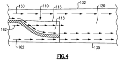
- Figure 4 schematically illustrates a cross sectional side view of the gas discharge outlet 110 of Figure 3 drawn along a cross sectional line B-B.
- the gas discharge outlet 110 is disposed on an inner diameter wall 130 of the duct 120.
- a flowpath 160 illustrates a flow of relatively cool air through the duct 120. As the cool air approaches and enters the valley 118, the flowpath 160 travels radially inward. As the downstream edge of the valley 118 is at approximately zero degrees, relative to the inner diameter wall 130, the cool air traveling along the flowpath 160 through the duct 120 passes the downstream edge of the gas discharge outlet 110 in a generally axial direction.
- a second flowpath 162 defines the fluid flow through the gas discharge outlet 110.
- the downstream edge of peak 116 is aligned with the inner diameter wall 130, the discharged heated exhaust is not oriented radially outward and the hot flow 162 remains along the inner diameter wall 130.
- the downstream edge of the lobed discharge outlet can be angled radially inward, driving the heated discharge toward the inner diameter wall 130.
- Figure 5 is a schematic side view of a duct 400 including a gas discharge 410 having a lobed fairing 420 according to the above example.
- the lobed fairing 420 defines three airflow regions downstream of a downstream edge 422.
- the first region is referred to as a cool region 430
- the second region is referred to as a mixed region 432
- the third region is referred to as a hot region 434.
- the cool region 430 is a region of the duct 400 where only cool air from the duct flowpath upstream of the gas discharge 410 is present.
- the mixed region 432 is a region where the cool air is mixed with hot air from the gas discharge 410.
- the mixed region 432 initially consists of unmixed hot air and cool air at downstream edge 422, there exists a maximum temperature that decreases the farther the air is downstream from the downstream edge 422 and a minimum temperature that increases the farther the air is downstream from downstream edge 422.
- the cool air from the cool air region 430 has had sufficient time to cool the hot air from the gas discharge 410 to below the maximum temperature of the outer diameter wall 402 material.
- the hot air region 434 is defined along the inner diameter surface 404 and does not extend the full radial height of the duct 400 until after the hot air passes through an exit nozzle 446 of the duct 400.
- the hot region 434 may extend the full radial height of the duct 400 after the hot air has traveled sufficiently downstream.
- the width 142, 146 and height 144, 148 dimensions of the peaks 116 and valleys 118 are configured to control the relative sizes and positions of the mixed air region 432 and the hot air region 434.
- the lobe height 144 determines the size of the mixed region 432 and hot air region 434, with an increased lobe height 144 increasing the size of the mixed region 432 and hot air region 434.
- the valley height 148 determines the positioning of the boundary between the mixed region 432 and the hot region 434. The longer the valley height 148, the closer the valley extends to the inner diameter 404, and the closer the boundary between the mixed region 432 and the hot region 434 is to the inner diameter 404.
- the ratio of the lobe width 142 to the valley width 146 determines the ratio of hot air to cool air in the mixed region 432, thereby controlling the temperature of the mixed region 432.
- the ratio of the cross sectional area of the lobe, normal to flow, to the cross sectional area of the valley 118, normal to flow determines the mix.
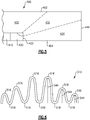
- Figure 6 schematically illustrates an alternate lobe configuration of a gas discharge outlet 510.
- the gas discharge outlet 510 includes multiple lobes with a cross sectional area defined by peaks 516 and their adjacent valleys 518.
- a peak height 544 decreases towards the outer edges of the gas discharge outlet 110 in a symmetrical manner.
- the decreasing lobe heights 544 result in a decreasing cross sectional area of each lobe and is utilized to control the radial height of the mixed region at the circumferential edges of the gas discharge outlet 110.
- the fairing 112 can be constructed of any material having suitable thermal and shaping properties.
- the fairing 112 could be cast, constructed of pressed sheet metal, milled from a material block, additively manufactured, or constructed using any similar technique.
- gas discharge fairing configuration can be applied to any gas turbine engine, including a direct drive engine, geared turbofan, and the like, as well as can be applied to non-thrust producing turbines such as land based turbines.
- lobed fairing configuration can be adjusted for utilization in an infinite radius duct with minimal changes, and such utilization is within the scope of this disclosure.
Landscapes
- Engineering & Computer Science (AREA)
- Chemical & Material Sciences (AREA)
- Combustion & Propulsion (AREA)
- Mechanical Engineering (AREA)
- General Engineering & Computer Science (AREA)
- Turbine Rotor Nozzle Sealing (AREA)
Abstract
Description
- The present disclosure relates generally to gas turbine engines, and more specifically to a gas turbine engine including a lobed gas discharge outlet protruding into a duct.
- A gas turbine engine typically includes a fan section and a core engine section with the core engine section including a compressor section, a combustor section and a turbine section. Air entering the compressor section is compressed and delivered into the combustor section where it is mixed with fuel and ignited to generate an exhaust gas flow. The exhaust gas flow expands through the turbine section to drive the compressor and the fan section. In some examples, the exhaust gas flow is also accelerated through an exhaust nozzle to generate thrust.
- The fan section drives air through a first bypass passage defined about the core engine. High bypass turbine engines include large bypass passages as compared to airflow through the core engine section and are suited for fuel efficient operation. Engines for applications in high speed aircraft include smaller bypass passages and generate more thrust from the core engine section. Fuel efficiency is increased by utilizing the bypass passage to generate thrust. Greater thrust is generated with more flow through the core engine section as relative to the bypass passage. Fuel efficiency is therefore balanced against aircraft thrust requirements and therefore, smaller bypass passages are utilized to provide higher thrust requirements that sacrifice some fuel efficiency.
- A variable cycle gas turbine engine can switch between highly fuel efficient operation with an increased amount of bypass airflow and high speed operation with less bypass airflow and more thrust produced from the core engine section through the exhaust nozzle.
- Although variable cycle gas turbine engines have improved operational efficiency, turbine engine manufacturers continue to seek further improvements to engine performance including improvements to thermal, transfer and propulsive efficiencies.
- A gas turbine engine according to one disclosed non-limiting embodiment includes an engine core including a primary flowpath, a first bypass duct positioned radially outward of the core engine, a gas discharge protruding radially into the first bypass duct, the gas discharge including a fairing defining a lobed outlet, and wherein the lobed outlet includes a plurality of axially aligned peaks and axially aligned valleys, each of the axially aligned valleys being configured to prevent a fluid passing through the valley from traveling radially inward immediately downstream of the fairing.
- An example of the above described gas turbine engine further includes a second bypass duct disposed between the first bypass duct and the engine core.
- In another example of any of the above described gas turbine engines the gas discharge is connected to a heat exchanger outlet.
- In another example of any of the above described gas turbine engines the first bypass duct is defined by an outer diameter wall and an inner diameter wall, and wherein the outer diameter wall is comprised of a first material having a first maximum temperature and the inner diameter wall is comprised of a second material having a second maximum temperature.
- In another example of any of the above described gas turbine engines the second maximum temperature is greater than the first maximum temperature.
- In another example of any of the above described gas turbine engines the outer diameter wall further comprises one of the second material and a third material downstream of the first material, the third material having a higher maximum temperature than the first material.
- In another example of any of the above described gas turbine engines the third material has a higher maximum temperature than an expected discharge temperature of the lobed outlet.
- In another example of any of the above described gas turbine engines the lobed outlet is configured to define a cool air region, a mixed air region and a hot air region within the first bypass duct.
- In another example of any of the above described gas turbine engines the hot air region extends along the inner diameter of the first bypass duct.
- In another example of any of the above described gas turbine engines the hot air region extends only a partial radial height of the first bypass duct.
- In another example of any of the above described gas turbine engines the hot air region extends a full radial height of the first bypass duct at a portion of the first bypass duct including an outer wall comprised of a third material.
- In another example of any of the above described gas turbine engines the portion of the outer wall comprised of the third material is a nozzle.
- In another example of any of the above described gas turbine engines each of the axially aligned valleys defines an axial flowpath immediately downstream of an aft edge of the lobed outlet.
- In another example of any of the above described gas turbine engines each of the axially aligned valleys defines a radially outwardly directed flowpath immediately downstream of an aft edge of the lobed outlet.
- In another example of any of the above described gas turbine engines each of the axially aligned peaks defines a radially inwardly directed flowpath immediately downstream of an aft edge of the lobed outlet.
- In another example of any of the above described gas turbine engines the plurality of axially aligned peaks and axially aligned valleys includes at least a first set of peaks having a first height and a second set of peaks having a second height, the first height being different from the second height.
- A gas discharge outlet according to another disclosed non-limiting embodiment includes a heated fluid source including an exhaust outlet, a fairing connected to the exhaust outlet and configured to direct exhausted fluid into a duct, and at least one of the plurality of valleys and the plurality of peaks being configured to define a fluid flow such that the exhausted fluid flow is constrained to an inner diameter of the duct for at least a length of the duct.
- In an example of the above described gas discharge outlet the fairing is aligned with an expected fluid flow direction and includes a plurality of peaks and a plurality of valleys having cross sections at least approximately normal to the expected fluid flow direction.
- In another example of any of the above described gas discharge outlet the plurality of valleys are one axially aligned at a downstream edge of the fairing and angled radially outward at the downstream edge of the fairing.
- In another example of any of the above described gas discharge outlet the plurality of peaks are one of axially aligned at a downstream edge of the fairing and angled radially inward at the downstream edge of the fairing.
- These and other features disclosed herein can be best understood from the following specification and drawings, the following of which is a brief description.
-
-
Figure 1 is a schematic view of an example gas turbine engine. -
Figure 2 is a schematic isometric view of an exhaust outlet fairing within a duct. -
Figure 3 is a forward view of the gas discharge outlet fairing ofFigure 2 . -
Figure 4 is a cross sectional side view of the gas discharge outlet fairing ofFigure 3 drawn along a cross sectional line B-B. -
Figure 5 is a schematic side view of a duct including a gas discharge having a lobed fairing. -
Figure 6 is a forward view of an alternate gas discharge outlet fairing. -
Figure 1 schematically illustrates a variable cyclegas turbine engine 10 that includes afan 12 and acore engine 24. Thecore engine 24 includes acompressor 14 that compresses air and supplies that air to acombustor 16 where the compressed air is mixed with fuel and ignited to generate an exhaust gas flow that expands through aturbine section 18. Theturbine section 18 in turn drives thecompressor section 14 and thefan 12. - The example
gas turbine engine 10 also includes anaugmenter section 20 where additional fuel from acore flow path 38 can be mixed with exhaust gasses and ignited to generate additional thrust. The exhaust gas or core flow 26 flows through anozzle 22 that includes a convergent/divergent portion to produce thrust. - The
example engine 10 includes afirst bypass passage 28 that is disposed annularly around thecore engine 24 and asecond bypass passage 30 that is disposed radially outward of thefirst bypass passage 28. Afirst bypass airflow 32 passing through thefirst bypass passage 28 and asecond bypass airflow 34 passing through thesecond bypass passage 30 provide for an increased efficiency of thrust production by theengine 10.Bypass airflows bypass passages gas turbine engine 10. Accordingly, airflow through the first andsecond bypass passages - The
example engine 10 includes aheat exchanger 50 as part of the engine cooling systems. While illustrated in theexample engine 10 as being disposed on an outer diameter of thefirst bypass passage 28, theheat exchanger 50 could be disposed at any position within theexample engine 10 and still operate as described herein. During the course of operations, theheat exchanger 50 ingests cold air which is then used to cool a cooling airflow. The ingested cold air is heated as a result of the cooling process, and theheat exchanger 50 exhausts spent (heated) air. The exhausted air is expelled into a duct, such as thesecond bypass passage 30, via agas discharge 52 that is connected to the outlet. While illustrated herein as being the same axial position as theturbine section 18, it is understood that thegas discharge 52 can be positioned in alternate positions within a givenbypass passage specific engine 10. - In some engines, such as the
example engine 10 ofFigure 1 , aninner diameter wall 62 and anouter diameter wall 64 of one or both of thebypass passages outer diameter wall 64 having a lower maximum temperature than theinner diameter wall 62. Further, in some configurations the spent air being expelled into thebypass passage 30 via thegas discharge 52 is hotter than the maximum temperature of theouter diameter wall 64 material. In alternative examples, theouter diameter wall 64 can include a downstream portion constructed of a third material having a higher maximum temperature than the discharged gas. By way of example, the downstream portion would be a nozzle section of thebypass duct 64. - With continued reference to
Figure 1 ,Figure 2 schematically illustrates an exemplarygas discharge outlet 110 within aduct 120, such as could be used as thegas discharge 52 ofFigure 1 . Thegas discharge outlet 110 protrudes radially outward into theduct 120 from aninner diameter wall 130, and includes a shapedfairing 112. The shapedfairing 112 defines alobed outlet 114 includingmultiple peaks 116 andvalleys 118. - The
lobed outlet 114 directs the discharged gas, as well as gases already flowing through theduct 120, such that the discharged gas travels along theinner diameter wall 130, and does not spread to theouter diameter wall 132 until the discharged gas has traveled sufficiently downstream such that the discharged gas has cooled below the maximum temperature threshold of theouter diameter wall 132 material. In alternative examples, thelobed outlet 114 can be configured such that the discharged gas does not reach a radial position of theouter diameter wall 132 until after the discharged gas has exited theduct 120 entirely. - With continued reference to
Figure 2 ,Figure 3 schematically illustrates a forward view of thegas discharge outlet 110 ofFigure 2 . Thelobed outlet 114 includesmultiple peaks 116 andvalleys 118. Each of thevalleys 118 defines a downwardsloping region 119 on the shaped fairing 112 that causes airflow within the duct 120 (seeFigure 2 ) to flow radially inward as the airflow through the duct approaches thelobed outlet 114. In contrast to thevalleys 118, thepeaks 116 are shaped such that the heated flow exiting thelobed outlet 114 maintains a generally constant radial extent from theinner diameter wall 130 of theduct 120. In some alternative examples, thepeaks 116 can be further angled radially inward, directing the gas discharge toward theinner diameter wall 130 of theduct 120. In such examples, the hot discharge flowing out of thelobed outlet 114 is maintained at or near theinner diameter wall 130 for a longer distance away from thelobed outlet 114. - Similarly, in alternative examples, the angle of the shaped fairing 112 at the edge of the
valleys 118 can be radially outward, relative to an axis defined by the engine, thereby directing the cool air back toward theouter diameter wall 132, rather than axially. - Each of the
peaks 116 defines alobe 140 having awidth 142 and aheight 144. Theheight 144 is aligned with a radius of theinner diameter wall 130 and defines the distance between the peak and theinner diameter wall 130. Thewidth 142 is aligned with a circumference of theinner diameter wall 130. Also defining eachlobe 140 are theadjacent valleys 118, each of which includes awidth 146 and aheight 148, with thewidth 146 and theheight 148 of theadjacent valleys 118 being generally aligned with thewidth 142 andheight 144 of thecorresponding peak 116. - With continued reference to
Figure 3 ,Figure 4 schematically illustrates a cross sectional side view of thegas discharge outlet 110 ofFigure 3 drawn along a cross sectional line B-B. Thegas discharge outlet 110 is disposed on aninner diameter wall 130 of theduct 120. Aflowpath 160 illustrates a flow of relatively cool air through theduct 120. As the cool air approaches and enters thevalley 118, theflowpath 160 travels radially inward. As the downstream edge of thevalley 118 is at approximately zero degrees, relative to theinner diameter wall 130, the cool air traveling along theflowpath 160 through theduct 120 passes the downstream edge of thegas discharge outlet 110 in a generally axial direction. - A
second flowpath 162 defines the fluid flow through thegas discharge outlet 110. As the downstream edge ofpeak 116 is aligned with theinner diameter wall 130, the discharged heated exhaust is not oriented radially outward and thehot flow 162 remains along theinner diameter wall 130. In yet further exemplary embodiments, the downstream edge of the lobed discharge outlet can be angled radially inward, driving the heated discharge toward theinner diameter wall 130. - With continued reference to
Figures 3 and4 ,Figure 5 is a schematic side view of aduct 400 including agas discharge 410 having alobed fairing 420 according to the above example. Thelobed fairing 420 defines three airflow regions downstream of adownstream edge 422. The first region is referred to as acool region 430, the second region is referred to as amixed region 432, and the third region is referred to as ahot region 434. Thecool region 430 is a region of theduct 400 where only cool air from the duct flowpath upstream of thegas discharge 410 is present. Themixed region 432 is a region where the cool air is mixed with hot air from thegas discharge 410. As themixed region 432 initially consists of unmixed hot air and cool air atdownstream edge 422, there exists a maximum temperature that decreases the farther the air is downstream from thedownstream edge 422 and a minimum temperature that increases the farther the air is downstream fromdownstream edge 422. As themixed region 432 does not contact theouter diameter wall 402 until a substantial distance downstream of thedownstream edge 422, the cool air from thecool air region 430 has had sufficient time to cool the hot air from thegas discharge 410 to below the maximum temperature of theouter diameter wall 402 material. Thehot air region 434 is defined along theinner diameter surface 404 and does not extend the full radial height of theduct 400 until after the hot air passes through anexit nozzle 446 of theduct 400. In alternative configurations, where the outer diameter of theduct 400 includes a downstream portion constructed of a material with a high maximum temperature, thehot region 434 may extend the full radial height of theduct 400 after the hot air has traveled sufficiently downstream. - With reference to
Figures 3 and5 , thewidth height peaks 116 andvalleys 118 are configured to control the relative sizes and positions of themixed air region 432 and thehot air region 434. Thelobe height 144 determines the size of themixed region 432 andhot air region 434, with an increasedlobe height 144 increasing the size of themixed region 432 andhot air region 434. Similarly, thevalley height 148 determines the positioning of the boundary between themixed region 432 and thehot region 434. The longer thevalley height 148, the closer the valley extends to theinner diameter 404, and the closer the boundary between themixed region 432 and thehot region 434 is to theinner diameter 404. Further, the ratio of thelobe width 142 to thevalley width 146 determines the ratio of hot air to cool air in themixed region 432, thereby controlling the temperature of themixed region 432. In alternative examples, where the lobes may not be uniform in shape, the ratio of the cross sectional area of the lobe, normal to flow, to the cross sectional area of thevalley 118, normal to flow determines the mix. - With continued reference to
Figure 3 ,Figure 6 schematically illustrates an alternate lobe configuration of agas discharge outlet 510. As with the example ofFigure 3 , thegas discharge outlet 510 includes multiple lobes with a cross sectional area defined bypeaks 516 and theiradjacent valleys 518. Unlike the example ofFigure 3 , however, apeak height 544 decreases towards the outer edges of thegas discharge outlet 110 in a symmetrical manner. The decreasinglobe heights 544 result in a decreasing cross sectional area of each lobe and is utilized to control the radial height of the mixed region at the circumferential edges of thegas discharge outlet 110. - With reference to all of the above described examples, the fairing 112 can be constructed of any material having suitable thermal and shaping properties. By way of example, the fairing 112 could be cast, constructed of pressed sheet metal, milled from a material block, additively manufactured, or constructed using any similar technique.
- While described herein as applied to a particular exemplary gas turbine engine, it should be appreciated that the gas discharge fairing configuration can be applied to any gas turbine engine, including a direct drive engine, geared turbofan, and the like, as well as can be applied to non-thrust producing turbines such as land based turbines. Further, the lobed fairing configuration can be adjusted for utilization in an infinite radius duct with minimal changes, and such utilization is within the scope of this disclosure.
- Although an example embodiment has been disclosed, a worker of ordinary skill in this art would recognize that certain modifications would come within the scope of this disclosure. For that reason, the following claims should be studied to determine the scope and content of this disclosure.
Claims (15)
- A gas turbine engine (10) comprising:an engine core (24) including a primary flowpath (38);a first bypass duct (28, 120, 400) positioned radially outward of the engine core (24); anda gas discharge (52, 410) protruding radially into the first bypass duct (28, 400), the gas discharge (52, 410) including a fairing (112, 420) defining a lobed outlet (110; 510), wherein the lobed outlet (110; 510) includes a plurality of axially aligned peaks (116; 516) and axially aligned valleys (118; 518), each of the axially aligned valleys (118; 518) being configured to prevent a fluid passing through the valley (118; 518) from travelling radially inward immediately downstream of the fairing (112, 420).
- The gas turbine engine (10) of claim 1, further comprising a second bypass duct (30) disposed between the first bypass duct (28, 120, 400) and the engine core (24).
- The gas turbine engine (10) of claim 1 or 2, wherein the gas discharge (52, 410) is connected to a heat exchanger outlet.
- The gas turbine engine (10) of any of claims 1 to 3, wherein the first bypass duct (28, 120, 400) is defined by an outer diameter wall (132, 402) and an inner diameter wall (130, 404), and wherein the outer diameter wall (132, 402) is comprised of a first material having a first maximum temperature and the inner diameter wall (130, 404) is comprised of a second material having a second maximum temperature, optionally, wherein the second maximum temperature is greater than the first maximum temperature.
- The gas turbine engine (10) of claim 4, wherein the outer diameter wall (132, 402) further comprises one of the second material and a third material downstream of the first material, the third material having a higher maximum temperature than the first material, wherein the third material optionally has a higher maximum temperature than an expected discharge temperature of the lobed outlet (110, 510).
- The gas turbine engine (10) of any preceding claim, wherein the lobed outlet (110, 510) is configured to define a cool air region (430), a mixed air region (432) and a hot air region (434) within the first bypass duct (28, 120, 400), wherein the hot air region (434) optionally extends along the inner diameter of the first bypass duct (28, 120, 400).
- The gas turbine engine (10) of claim 6, wherein the hot air region (434) extends only a partial radial height of the first bypass duct (28, 120, 400).
- The gas turbine engine (10) of claim 6, wherein the hot air region (434) extends a full radial height of the first bypass duct (28, 120, 400) at a portion of the first bypass duct (28, 120, 400) including a or the outer diameter wall (132, 402) comprised of a third material, wherein the portion of the outer diameter wall (132, 402) comprised of the third material is optionally a nozzle (22).
- The gas turbine engine (10) of any preceding claim, wherein each of the axially aligned valleys (118; 518) defines an axial flowpath immediately downstream of an aft edge of the lobed outlet (110; 510).
- The gas turbine engine (10) of any of claims 1 to 8, wherein each of the axially aligned valleys (118; 518) defines a radially outwardly directed flowpath immediately downstream of an aft edge of the lobed outlet (110; 510).
- The gas turbine engine (10) of any preceding claim, wherein each of the axially aligned peaks (116; 516) defines a radially inwardly directed flowpath immediately downstream of an aft edge of the lobed outlet (110; 510).
- The gas turbine engine (10) of any preceding claim, wherein the plurality of axially aligned peaks (516) and axially aligned valleys (518) includes at least a first set of peaks (516) having a first height (544) and a second set of peaks (516) having a second height (544), the first height (544) being different from the second height (544).
- A gas discharge outlet comprising:a heated fluid source including an exhaust outlet; anda fairing (112, 420) connected to the exhaust outlet and configured to direct exhausted fluid into a duct (28, 120, 400), the fairing (112, 420) defining a plurality of valleys (118; 518) and a plurality of peaks (116; 516), at least one of the plurality of valleys (118; 518) and the plurality of peaks (116; 516) being configured to define a fluid flow such that the exhausted fluid flow is constrained to an inner diameter of the duct (28, 120, 400) for at least a length of the duct (28, 120, 400).
- The gas discharge outlet of claim 13, wherein the fairing (112, 420) is aligned with an expected fluid flow direction and includes a plurality of peaks (116; 516) and a plurality of valleys (118; 518) having cross sections at least approximately normal to the expected fluid flow direction, wherein:the plurality of valleys (118; 518) are optionally one of axially aligned at a downstream edge of the fairing (112, 420) and angled radially outward at the downstream edge of the fairing (112, 420); and/orthe plurality of peaks (116; 516) are optionally one of axially aligned at a downstream edge of the fairing (112, 420) and angled radially inward at the downstream edge of the fairing (112, 420).
- A method for preventing an outer diameter wall (132, 402) from thermal exposure comprising exhausting heated fluid into a duct (28, 120, 400) using a lobed fairing (112, 420), the lobed fairing (112, 420) defining a cool fluid region (430), a mixed fluid region (432), and a hot fluid region (434), wherein the hot fluid region (434) extends only a partial radial height of the duct (28, 120, 400), wherein, optionally, a size of the mixed fluid region (432) is defined by a lobe height (144; 544) of the lobed fairing (112, 420), a radial position of a boundary between the mixed fluid region (432) and the hot fluid region (434) is defined by a valley height (148) of the lobed fairing (112, 420), and a temperature of the mixed fluid region (432) being controlled by a ratio of a lobe cross sectional area to a valley cross sectional area of the lobed fairing (112, 420).
Applications Claiming Priority (1)
| Application Number | Priority Date | Filing Date | Title |
|---|---|---|---|
| US15/674,824 US11199134B2 (en) | 2017-08-11 | 2017-08-11 | Lobed gas discharge fairing for a turbofan engine |
Publications (2)
| Publication Number | Publication Date |
|---|---|
| EP3441593A1 true EP3441593A1 (en) | 2019-02-13 |
| EP3441593B1 EP3441593B1 (en) | 2022-07-13 |
Family
ID=63207553
Family Applications (1)
| Application Number | Title | Priority Date | Filing Date |
|---|---|---|---|
| EP18188087.3A Active EP3441593B1 (en) | 2017-08-11 | 2018-08-08 | Lobed gas discharge fairing for a turbofan engine |
Country Status (2)
| Country | Link |
|---|---|
| US (1) | US11199134B2 (en) |
| EP (1) | EP3441593B1 (en) |
Cited By (2)
| Publication number | Priority date | Publication date | Assignee | Title |
|---|---|---|---|---|
| CN113464277A (en) * | 2021-07-15 | 2021-10-01 | 哈尔滨工程大学 | Ship gas turbine with special-shaped lobe ejecting mixer |
| CN119914432A (en) * | 2025-01-06 | 2025-05-02 | 南京航空航天大学 | A lobe-type front duct ejector with mixing enhancement function |
Families Citing this family (2)
| Publication number | Priority date | Publication date | Assignee | Title |
|---|---|---|---|---|
| CN112228226A (en) * | 2020-10-16 | 2021-01-15 | 中国航发四川燃气涡轮研究院 | Aircraft engine turbine rotor cooling thermal management system |
| FR3159416A1 (en) * | 2024-02-19 | 2025-08-22 | Safran Aircraft Engines | Assembly for aircraft propulsion system, comprising equipment crossed by a gas flow and equipped with a flow mixer |
Citations (3)
| Publication number | Priority date | Publication date | Assignee | Title |
|---|---|---|---|---|
| EP0924407A2 (en) * | 1997-12-22 | 1999-06-23 | United Technologies Corporation | Inlet and outlet module for a gas turbine engine heat exchanger |
| EP2020500A2 (en) * | 2007-07-30 | 2009-02-04 | General Electric Company | Heat exchanger assembly for gas turbine engines |
| US20150167549A1 (en) * | 2013-06-07 | 2015-06-18 | United Technologies Corporation | Exhaust stream mixer |
Family Cites Families (11)
| Publication number | Priority date | Publication date | Assignee | Title |
|---|---|---|---|---|
| US5269135A (en) | 1991-10-28 | 1993-12-14 | General Electric Company | Gas turbine engine fan cooled heat exchanger |
| US6106229A (en) | 1997-12-22 | 2000-08-22 | United Technologies Corporation | Heat exchanger system for a gas turbine engine |
| US8726665B2 (en) * | 2007-06-05 | 2014-05-20 | The Boeing Company | Internal mixing of a portion of fan exhaust flow and full core exhaust flow in aircraft turbofan engines |
| US7762057B2 (en) * | 2007-06-05 | 2010-07-27 | The Boeing Company | Internal mixing of a portion of fan exhaust flow and full core exhaust flow in aircraft turbofan engines |
| CN104379918B (en) * | 2012-04-27 | 2017-12-12 | 通用电气公司 | Mixer for gas turbine engine, manufacturing method thereof, and gas turbine engine |
| US10072584B2 (en) * | 2013-12-03 | 2018-09-11 | United Technologies Corporation | Multi-bypass stream gas turbine engine with enlarged bypass flow area |
| US9964037B2 (en) * | 2014-02-26 | 2018-05-08 | United Technologies Corporation | Staged heat exchangers for multi-bypass stream gas turbine engines |
| US9574518B2 (en) * | 2014-06-02 | 2017-02-21 | The Boeing Company | Turbofan engine with variable exhaust cooling |
| US10119477B2 (en) * | 2015-01-20 | 2018-11-06 | United Technologies Corporation | Gas turbine engine with a multi-spool driven fan |
| US10161316B2 (en) * | 2015-04-13 | 2018-12-25 | United Technologies Corporation | Engine bypass valve |
| US9551239B2 (en) * | 2015-04-22 | 2017-01-24 | Rohr, Inc. | Exhaust assembly center body |
-
2017
- 2017-08-11 US US15/674,824 patent/US11199134B2/en active Active
-
2018
- 2018-08-08 EP EP18188087.3A patent/EP3441593B1/en active Active
Patent Citations (3)
| Publication number | Priority date | Publication date | Assignee | Title |
|---|---|---|---|---|
| EP0924407A2 (en) * | 1997-12-22 | 1999-06-23 | United Technologies Corporation | Inlet and outlet module for a gas turbine engine heat exchanger |
| EP2020500A2 (en) * | 2007-07-30 | 2009-02-04 | General Electric Company | Heat exchanger assembly for gas turbine engines |
| US20150167549A1 (en) * | 2013-06-07 | 2015-06-18 | United Technologies Corporation | Exhaust stream mixer |
Cited By (2)
| Publication number | Priority date | Publication date | Assignee | Title |
|---|---|---|---|---|
| CN113464277A (en) * | 2021-07-15 | 2021-10-01 | 哈尔滨工程大学 | Ship gas turbine with special-shaped lobe ejecting mixer |
| CN119914432A (en) * | 2025-01-06 | 2025-05-02 | 南京航空航天大学 | A lobe-type front duct ejector with mixing enhancement function |
Also Published As
| Publication number | Publication date |
|---|---|
| US11199134B2 (en) | 2021-12-14 |
| US20190048731A1 (en) | 2019-02-14 |
| EP3441593B1 (en) | 2022-07-13 |
Similar Documents
| Publication | Publication Date | Title |
|---|---|---|
| US9879603B2 (en) | Axial flow machine cooling system | |
| EP1939397B1 (en) | Turbine nozzle with bullnose step-down platform | |
| CN107178425B (en) | A gas turbine engine and a vent assembly therein | |
| EP2236750B1 (en) | An impingement cooling arrangement for a gas turbine engine | |
| US8973374B2 (en) | Blades in a turbine section of a gas turbine engine | |
| US9097140B2 (en) | Cavity ventilation | |
| US10113486B2 (en) | Method and system for modulated turbine cooling | |
| EP3441593B1 (en) | Lobed gas discharge fairing for a turbofan engine | |
| JPH0120320B2 (en) | ||
| US10378478B2 (en) | Flow path routing within a gas turbine engine | |
| CN107013268A (en) | Compression radome fairing for jet engine exhaust | |
| US7866947B2 (en) | Turbine blade trip strip orientation | |
| EP3048282B1 (en) | A gas turbine engine and blocker door assembly | |
| EP3199779B1 (en) | Cooling air for variable geometry turbine | |
| US20190170009A1 (en) | Turbine engine with clearance control system | |
| EP3569841B1 (en) | Intercooled cooling air with heat exchanger packaging | |
| US12584421B2 (en) | Heat exchanger with inlet and outlet turning vanes for use in gas turbine engines | |
| US11002300B2 (en) | Flow conditioning system | |
| US11808210B2 (en) | Intercooled cooling air with heat exchanger packaging | |
| EP3464827B1 (en) | Converging duct for a gas turbine engine and gas turbine engine | |
| EP3032038B1 (en) | Pre-diffuser of a gas turbine engine, gas turbine engine and method of forming a pre-diffuser of a gas turbine engine | |
| WO2013137960A1 (en) | Turbine blades in a gas turbine engine |
Legal Events
| Date | Code | Title | Description |
|---|---|---|---|
| PUAI | Public reference made under article 153(3) epc to a published international application that has entered the european phase |
Free format text: ORIGINAL CODE: 0009012 |
|
| STAA | Information on the status of an ep patent application or granted ep patent |
Free format text: STATUS: THE APPLICATION HAS BEEN PUBLISHED |
|
| AK | Designated contracting states |
Kind code of ref document: A1 Designated state(s): AL AT BE BG CH CY CZ DE DK EE ES FI FR GB GR HR HU IE IS IT LI LT LU LV MC MK MT NL NO PL PT RO RS SE SI SK SM TR |
|
| AX | Request for extension of the european patent |
Extension state: BA ME |
|
| STAA | Information on the status of an ep patent application or granted ep patent |
Free format text: STATUS: REQUEST FOR EXAMINATION WAS MADE |
|
| 17P | Request for examination filed |
Effective date: 20190813 |
|
| RBV | Designated contracting states (corrected) |
Designated state(s): AL AT BE BG CH CY CZ DE DK EE ES FI FR GB GR HR HU IE IS IT LI LT LU LV MC MK MT NL NO PL PT RO RS SE SI SK SM TR |
|
| STAA | Information on the status of an ep patent application or granted ep patent |
Free format text: STATUS: EXAMINATION IS IN PROGRESS |
|
| 17Q | First examination report despatched |
Effective date: 20201217 |
|
| RAP1 | Party data changed (applicant data changed or rights of an application transferred) |
Owner name: RAYTHEON TECHNOLOGIES CORPORATION |
|
| GRAP | Despatch of communication of intention to grant a patent |
Free format text: ORIGINAL CODE: EPIDOSNIGR1 |
|
| STAA | Information on the status of an ep patent application or granted ep patent |
Free format text: STATUS: GRANT OF PATENT IS INTENDED |
|
| INTG | Intention to grant announced |
Effective date: 20210909 |
|
| GRAJ | Information related to disapproval of communication of intention to grant by the applicant or resumption of examination proceedings by the epo deleted |
Free format text: ORIGINAL CODE: EPIDOSDIGR1 |
|
| STAA | Information on the status of an ep patent application or granted ep patent |
Free format text: STATUS: EXAMINATION IS IN PROGRESS |
|
| GRAP | Despatch of communication of intention to grant a patent |
Free format text: ORIGINAL CODE: EPIDOSNIGR1 |
|
| STAA | Information on the status of an ep patent application or granted ep patent |
Free format text: STATUS: GRANT OF PATENT IS INTENDED |
|
| INTC | Intention to grant announced (deleted) | ||
| INTG | Intention to grant announced |
Effective date: 20220209 |
|
| GRAS | Grant fee paid |
Free format text: ORIGINAL CODE: EPIDOSNIGR3 |
|
| GRAA | (expected) grant |
Free format text: ORIGINAL CODE: 0009210 |
|
| STAA | Information on the status of an ep patent application or granted ep patent |
Free format text: STATUS: THE PATENT HAS BEEN GRANTED |
|
| AK | Designated contracting states |
Kind code of ref document: B1 Designated state(s): AL AT BE BG CH CY CZ DE DK EE ES FI FR GB GR HR HU IE IS IT LI LT LU LV MC MK MT NL NO PL PT RO RS SE SI SK SM TR |
|
| REG | Reference to a national code |
Ref country code: CH Ref legal event code: EP |
|
| REG | Reference to a national code |
Ref country code: DE Ref legal event code: R096 Ref document number: 602018037822 Country of ref document: DE |
|
| REG | Reference to a national code |
Ref country code: AT Ref legal event code: REF Ref document number: 1504407 Country of ref document: AT Kind code of ref document: T Effective date: 20220815 |
|
| REG | Reference to a national code |
Ref country code: IE Ref legal event code: FG4D |
|
| REG | Reference to a national code |
Ref country code: LT Ref legal event code: MG9D |
|
| REG | Reference to a national code |
Ref country code: NL Ref legal event code: MP Effective date: 20220713 |
|
| PG25 | Lapsed in a contracting state [announced via postgrant information from national office to epo] |
Ref country code: SE Free format text: LAPSE BECAUSE OF FAILURE TO SUBMIT A TRANSLATION OF THE DESCRIPTION OR TO PAY THE FEE WITHIN THE PRESCRIBED TIME-LIMIT Effective date: 20220713 Ref country code: RS Free format text: LAPSE BECAUSE OF FAILURE TO SUBMIT A TRANSLATION OF THE DESCRIPTION OR TO PAY THE FEE WITHIN THE PRESCRIBED TIME-LIMIT Effective date: 20220713 Ref country code: PT Free format text: LAPSE BECAUSE OF FAILURE TO SUBMIT A TRANSLATION OF THE DESCRIPTION OR TO PAY THE FEE WITHIN THE PRESCRIBED TIME-LIMIT Effective date: 20221114 Ref country code: NO Free format text: LAPSE BECAUSE OF FAILURE TO SUBMIT A TRANSLATION OF THE DESCRIPTION OR TO PAY THE FEE WITHIN THE PRESCRIBED TIME-LIMIT Effective date: 20221013 Ref country code: NL Free format text: LAPSE BECAUSE OF FAILURE TO SUBMIT A TRANSLATION OF THE DESCRIPTION OR TO PAY THE FEE WITHIN THE PRESCRIBED TIME-LIMIT Effective date: 20220713 Ref country code: LV Free format text: LAPSE BECAUSE OF FAILURE TO SUBMIT A TRANSLATION OF THE DESCRIPTION OR TO PAY THE FEE WITHIN THE PRESCRIBED TIME-LIMIT Effective date: 20220713 Ref country code: LT Free format text: LAPSE BECAUSE OF FAILURE TO SUBMIT A TRANSLATION OF THE DESCRIPTION OR TO PAY THE FEE WITHIN THE PRESCRIBED TIME-LIMIT Effective date: 20220713 Ref country code: FI Free format text: LAPSE BECAUSE OF FAILURE TO SUBMIT A TRANSLATION OF THE DESCRIPTION OR TO PAY THE FEE WITHIN THE PRESCRIBED TIME-LIMIT Effective date: 20220713 Ref country code: ES Free format text: LAPSE BECAUSE OF FAILURE TO SUBMIT A TRANSLATION OF THE DESCRIPTION OR TO PAY THE FEE WITHIN THE PRESCRIBED TIME-LIMIT Effective date: 20220713 |
|
| REG | Reference to a national code |
Ref country code: AT Ref legal event code: MK05 Ref document number: 1504407 Country of ref document: AT Kind code of ref document: T Effective date: 20220713 |
|
| PG25 | Lapsed in a contracting state [announced via postgrant information from national office to epo] |
Ref country code: PL Free format text: LAPSE BECAUSE OF FAILURE TO SUBMIT A TRANSLATION OF THE DESCRIPTION OR TO PAY THE FEE WITHIN THE PRESCRIBED TIME-LIMIT Effective date: 20220713 Ref country code: IS Free format text: LAPSE BECAUSE OF FAILURE TO SUBMIT A TRANSLATION OF THE DESCRIPTION OR TO PAY THE FEE WITHIN THE PRESCRIBED TIME-LIMIT Effective date: 20221113 Ref country code: HR Free format text: LAPSE BECAUSE OF FAILURE TO SUBMIT A TRANSLATION OF THE DESCRIPTION OR TO PAY THE FEE WITHIN THE PRESCRIBED TIME-LIMIT Effective date: 20220713 Ref country code: GR Free format text: LAPSE BECAUSE OF FAILURE TO SUBMIT A TRANSLATION OF THE DESCRIPTION OR TO PAY THE FEE WITHIN THE PRESCRIBED TIME-LIMIT Effective date: 20221014 |
|
| REG | Reference to a national code |
Ref country code: CH Ref legal event code: PL |
|
| REG | Reference to a national code |
Ref country code: DE Ref legal event code: R097 Ref document number: 602018037822 Country of ref document: DE |
|
| PG25 | Lapsed in a contracting state [announced via postgrant information from national office to epo] |
Ref country code: SM Free format text: LAPSE BECAUSE OF FAILURE TO SUBMIT A TRANSLATION OF THE DESCRIPTION OR TO PAY THE FEE WITHIN THE PRESCRIBED TIME-LIMIT Effective date: 20220713 Ref country code: RO Free format text: LAPSE BECAUSE OF FAILURE TO SUBMIT A TRANSLATION OF THE DESCRIPTION OR TO PAY THE FEE WITHIN THE PRESCRIBED TIME-LIMIT Effective date: 20220713 Ref country code: MC Free format text: LAPSE BECAUSE OF FAILURE TO SUBMIT A TRANSLATION OF THE DESCRIPTION OR TO PAY THE FEE WITHIN THE PRESCRIBED TIME-LIMIT Effective date: 20220713 Ref country code: LU Free format text: LAPSE BECAUSE OF NON-PAYMENT OF DUE FEES Effective date: 20220808 Ref country code: LI Free format text: LAPSE BECAUSE OF NON-PAYMENT OF DUE FEES Effective date: 20220831 Ref country code: DK Free format text: LAPSE BECAUSE OF FAILURE TO SUBMIT A TRANSLATION OF THE DESCRIPTION OR TO PAY THE FEE WITHIN THE PRESCRIBED TIME-LIMIT Effective date: 20220713 Ref country code: CZ Free format text: LAPSE BECAUSE OF FAILURE TO SUBMIT A TRANSLATION OF THE DESCRIPTION OR TO PAY THE FEE WITHIN THE PRESCRIBED TIME-LIMIT Effective date: 20220713 Ref country code: CH Free format text: LAPSE BECAUSE OF NON-PAYMENT OF DUE FEES Effective date: 20220831 Ref country code: AT Free format text: LAPSE BECAUSE OF FAILURE TO SUBMIT A TRANSLATION OF THE DESCRIPTION OR TO PAY THE FEE WITHIN THE PRESCRIBED TIME-LIMIT Effective date: 20220713 |
|
| REG | Reference to a national code |
Ref country code: BE Ref legal event code: MM Effective date: 20220831 |
|
| PLBE | No opposition filed within time limit |
Free format text: ORIGINAL CODE: 0009261 |
|
| STAA | Information on the status of an ep patent application or granted ep patent |
Free format text: STATUS: NO OPPOSITION FILED WITHIN TIME LIMIT |
|
| PG25 | Lapsed in a contracting state [announced via postgrant information from national office to epo] |
Ref country code: SK Free format text: LAPSE BECAUSE OF FAILURE TO SUBMIT A TRANSLATION OF THE DESCRIPTION OR TO PAY THE FEE WITHIN THE PRESCRIBED TIME-LIMIT Effective date: 20220713 Ref country code: EE Free format text: LAPSE BECAUSE OF FAILURE TO SUBMIT A TRANSLATION OF THE DESCRIPTION OR TO PAY THE FEE WITHIN THE PRESCRIBED TIME-LIMIT Effective date: 20220713 |
|
| 26N | No opposition filed |
Effective date: 20230414 |
|
| P01 | Opt-out of the competence of the unified patent court (upc) registered |
Effective date: 20230521 |
|
| PG25 | Lapsed in a contracting state [announced via postgrant information from national office to epo] |
Ref country code: AL Free format text: LAPSE BECAUSE OF FAILURE TO SUBMIT A TRANSLATION OF THE DESCRIPTION OR TO PAY THE FEE WITHIN THE PRESCRIBED TIME-LIMIT Effective date: 20220713 |
|
| PG25 | Lapsed in a contracting state [announced via postgrant information from national office to epo] |
Ref country code: IE Free format text: LAPSE BECAUSE OF NON-PAYMENT OF DUE FEES Effective date: 20220808 |
|
| PG25 | Lapsed in a contracting state [announced via postgrant information from national office to epo] |
Ref country code: SI Free format text: LAPSE BECAUSE OF FAILURE TO SUBMIT A TRANSLATION OF THE DESCRIPTION OR TO PAY THE FEE WITHIN THE PRESCRIBED TIME-LIMIT Effective date: 20220713 |
|
| PG25 | Lapsed in a contracting state [announced via postgrant information from national office to epo] |
Ref country code: BE Free format text: LAPSE BECAUSE OF NON-PAYMENT OF DUE FEES Effective date: 20220831 |
|
| PG25 | Lapsed in a contracting state [announced via postgrant information from national office to epo] |
Ref country code: IT Free format text: LAPSE BECAUSE OF FAILURE TO SUBMIT A TRANSLATION OF THE DESCRIPTION OR TO PAY THE FEE WITHIN THE PRESCRIBED TIME-LIMIT Effective date: 20220713 |
|
| PG25 | Lapsed in a contracting state [announced via postgrant information from national office to epo] |
Ref country code: HU Free format text: LAPSE BECAUSE OF FAILURE TO SUBMIT A TRANSLATION OF THE DESCRIPTION OR TO PAY THE FEE WITHIN THE PRESCRIBED TIME-LIMIT; INVALID AB INITIO Effective date: 20180808 |
|
| PG25 | Lapsed in a contracting state [announced via postgrant information from national office to epo] |
Ref country code: CY Free format text: LAPSE BECAUSE OF FAILURE TO SUBMIT A TRANSLATION OF THE DESCRIPTION OR TO PAY THE FEE WITHIN THE PRESCRIBED TIME-LIMIT Effective date: 20220713 |
|
| PG25 | Lapsed in a contracting state [announced via postgrant information from national office to epo] |
Ref country code: MK Free format text: LAPSE BECAUSE OF FAILURE TO SUBMIT A TRANSLATION OF THE DESCRIPTION OR TO PAY THE FEE WITHIN THE PRESCRIBED TIME-LIMIT Effective date: 20220713 |
|
| PG25 | Lapsed in a contracting state [announced via postgrant information from national office to epo] |
Ref country code: TR Free format text: LAPSE BECAUSE OF FAILURE TO SUBMIT A TRANSLATION OF THE DESCRIPTION OR TO PAY THE FEE WITHIN THE PRESCRIBED TIME-LIMIT Effective date: 20220713 |
|
| PG25 | Lapsed in a contracting state [announced via postgrant information from national office to epo] |
Ref country code: BG Free format text: LAPSE BECAUSE OF FAILURE TO SUBMIT A TRANSLATION OF THE DESCRIPTION OR TO PAY THE FEE WITHIN THE PRESCRIBED TIME-LIMIT Effective date: 20220713 |
|
| PG25 | Lapsed in a contracting state [announced via postgrant information from national office to epo] |
Ref country code: MT Free format text: LAPSE BECAUSE OF FAILURE TO SUBMIT A TRANSLATION OF THE DESCRIPTION OR TO PAY THE FEE WITHIN THE PRESCRIBED TIME-LIMIT Effective date: 20220713 |
|
| REG | Reference to a national code |
Ref country code: DE Ref legal event code: R081 Ref document number: 602018037822 Country of ref document: DE Owner name: RTX CORPORATION (N.D.GES.D. STAATES DELAWARE),, US Free format text: FORMER OWNER: RAYTHEON TECHNOLOGIES CORPORATION, FARMINGTON, CT, US |
|
| PGFP | Annual fee paid to national office [announced via postgrant information from national office to epo] |
Ref country code: DE Payment date: 20250724 Year of fee payment: 8 |
|
| PGFP | Annual fee paid to national office [announced via postgrant information from national office to epo] |
Ref country code: GB Payment date: 20250724 Year of fee payment: 8 |
|
| PGFP | Annual fee paid to national office [announced via postgrant information from national office to epo] |
Ref country code: FR Payment date: 20250725 Year of fee payment: 8 |