EP3441578A1 - Turbine exhaust diffuser - Google Patents
Turbine exhaust diffuser Download PDFInfo
- Publication number
- EP3441578A1 EP3441578A1 EP17461583.1A EP17461583A EP3441578A1 EP 3441578 A1 EP3441578 A1 EP 3441578A1 EP 17461583 A EP17461583 A EP 17461583A EP 3441578 A1 EP3441578 A1 EP 3441578A1
- Authority
- EP
- European Patent Office
- Prior art keywords
- seal
- exhaust diffuser
- forward portion
- diffuser
- exhaust
- Prior art date
- Legal status (The legal status is an assumption and is not a legal conclusion. Google has not performed a legal analysis and makes no representation as to the accuracy of the status listed.)
- Granted
Links
Images
Classifications
-
- F—MECHANICAL ENGINEERING; LIGHTING; HEATING; WEAPONS; BLASTING
- F01—MACHINES OR ENGINES IN GENERAL; ENGINE PLANTS IN GENERAL; STEAM ENGINES
- F01D—NON-POSITIVE DISPLACEMENT MACHINES OR ENGINES, e.g. STEAM TURBINES
- F01D25/00—Component parts, details, or accessories, not provided for in, or of interest apart from, other groups
- F01D25/30—Exhaust heads, chambers, or the like
-
- F—MECHANICAL ENGINEERING; LIGHTING; HEATING; WEAPONS; BLASTING
- F01—MACHINES OR ENGINES IN GENERAL; ENGINE PLANTS IN GENERAL; STEAM ENGINES
- F01D—NON-POSITIVE DISPLACEMENT MACHINES OR ENGINES, e.g. STEAM TURBINES
- F01D11/00—Preventing or minimising internal leakage of working-fluid, e.g. between stages
-
- F—MECHANICAL ENGINEERING; LIGHTING; HEATING; WEAPONS; BLASTING
- F01—MACHINES OR ENGINES IN GENERAL; ENGINE PLANTS IN GENERAL; STEAM ENGINES
- F01D—NON-POSITIVE DISPLACEMENT MACHINES OR ENGINES, e.g. STEAM TURBINES
- F01D11/00—Preventing or minimising internal leakage of working-fluid, e.g. between stages
- F01D11/005—Sealing means between non relatively rotating elements
-
- F—MECHANICAL ENGINEERING; LIGHTING; HEATING; WEAPONS; BLASTING
- F01—MACHINES OR ENGINES IN GENERAL; ENGINE PLANTS IN GENERAL; STEAM ENGINES
- F01D—NON-POSITIVE DISPLACEMENT MACHINES OR ENGINES, e.g. STEAM TURBINES
- F01D25/00—Component parts, details, or accessories, not provided for in, or of interest apart from, other groups
- F01D25/24—Casings; Casing parts, e.g. diaphragms, casing fastenings
-
- F—MECHANICAL ENGINEERING; LIGHTING; HEATING; WEAPONS; BLASTING
- F05—INDEXING SCHEMES RELATING TO ENGINES OR PUMPS IN VARIOUS SUBCLASSES OF CLASSES F01-F04
- F05D—INDEXING SCHEME FOR ASPECTS RELATING TO NON-POSITIVE-DISPLACEMENT MACHINES OR ENGINES, GAS-TURBINES OR JET-PROPULSION PLANTS
- F05D2220/00—Application
- F05D2220/30—Application in turbines
- F05D2220/32—Application in turbines in gas turbines
-
- F—MECHANICAL ENGINEERING; LIGHTING; HEATING; WEAPONS; BLASTING
- F05—INDEXING SCHEMES RELATING TO ENGINES OR PUMPS IN VARIOUS SUBCLASSES OF CLASSES F01-F04
- F05D—INDEXING SCHEME FOR ASPECTS RELATING TO NON-POSITIVE-DISPLACEMENT MACHINES OR ENGINES, GAS-TURBINES OR JET-PROPULSION PLANTS
- F05D2240/00—Components
- F05D2240/10—Stators
- F05D2240/12—Fluid guiding means, e.g. vanes
-
- F—MECHANICAL ENGINEERING; LIGHTING; HEATING; WEAPONS; BLASTING
- F05—INDEXING SCHEMES RELATING TO ENGINES OR PUMPS IN VARIOUS SUBCLASSES OF CLASSES F01-F04
- F05D—INDEXING SCHEME FOR ASPECTS RELATING TO NON-POSITIVE-DISPLACEMENT MACHINES OR ENGINES, GAS-TURBINES OR JET-PROPULSION PLANTS
- F05D2240/00—Components
- F05D2240/55—Seals
Definitions
- the present application and the resultant patent relate generally to gas turbine engines and more particularly to gas turbine engines with improved exhaust diffusers and diffuser seals configured to reduce out of round conditions.
- Gas turbine engines generally include an exhaust diffuser positioned downstream of the last stage of a turbine.
- the exhaust diffuser converts the kinetic energy of the hot combustion gases exiting the last stage of the turbine into potential energy in the form of increased static pressure.
- the exhaust diffuser directs the hot combustion gases through a casing of increasing cross-sectional area in the direction of the flow.
- the exhaust diffuser generally includes a number of struts mounted onto a hub and enclosed by the casing.
- Typical exhaust diffusers may be a continuous 360 degree circle or split into a number of segments in some fashion.
- the continuous diffuser may be the easiest to manufacture but a split diffuser may offer more operational flexibility including access to certain components in the field such as bearings and the like.
- the split diffusers may use tall radial flanges for sealing and/or attachment purposes. These tall flanges may experience stresses and thermal gradients along the length thereof that may result in a high out of round effect. An out of round condition in close proximity to the turbine exit may affect the overall aero-performance and gas turbine output and efficiency.
- the present application and the resulting patent thus provide an exhaust diffuser for a turbine.
- the exhaust diffuser may include an outer diffuser section with a forward portion.
- An outer forward seal system may be positioned on the forward portion.
- the outer forward seal system may include a seal base removably positioned in a seal pocket.
- the present application and the resulting patent further provide a method of operating an exhaust diffuser to limit out of round conditions.
- the method may include the steps of positioning a seal base in a seal pocket of a forward portion of the exhaust diffuser, locking the seal base into place via a channel extending through the forward portion from a flow side thereof, and flowing combustion gases past the forward portion on the flow side thereof.
- the present application and the resultant patent further provide an exhaust diffuser.
- the exhaust diffuser may include an outer diffuser section with a forward portion.
- An outer forward seal system may be positioned on the forward portion.
- the outer forward seal system may include a seal base with a seal member and a seal pocket formed within the forward portion.
- the seal member may be removably positioned therein and secured via a dowel extending through the forward portion.
- Fig. 1 shows a schematic view of gas turbine engine 10 as may be used herein.
- the gas turbine engine 10 may include a compressor 15.
- the compressor 15 compresses an incoming flow of air 20.
- the compressor 15 delivers the compressed flow of air 20 to a combustor 25.
- the combustor 25 mixes the compressed flow of air 20 with a pressurized flow of fuel 30 and ignites the mixture to create a flow of combustion gases 35.
- the gas turbine engine 10 may include any number of combustors 25 configured in a circumferential array and the like.
- the flow of combustion gases 35 is in turn delivered to a turbine 40.
- the flow of combustion gases 35 drives the turbine 40 so as to produce mechanical work.
- the mechanical work produced in the turbine 40 drives the compressor 15 via a shaft 45 and an external load 50 such as an electrical generator and the like.
- the gas turbine engine 10 may use natural gas, various types of syngas, liquid fuels, and/or other types of fuels and blends thereof.
- the gas turbine engine 10 may be any one of a number of different gas turbine engines offered by General Electric Company of Schenectady, New York, including, but not limited to, those such as a 7 or a 9 series heavy duty gas turbine engine and the like.
- the gas turbine engine 10 may have different configurations and may use other types of components. Other types of gas turbine engines also may be used herein. Multiple gas turbine engines, other types of turbines, and other types of power generation equipment also may be used herein together.
- the gas turbine engine 10 also may include an exhaust diffuser 55.
- the exhaust diffuser 55 may be positioned downstream of and in communication with the turbine 40.
- the exhaust diffuser 55 may include a number of struts 60 mounted on a hub 65 and enclosed within an outer casing 70.
- the struts 50 serve to hold the hub 65 and the casing 70 in a fixed relationship to one another.
- the exhaust diffuser 55 may turn the flow of the combustion gases 35 in a radial direction.
- the exhaust diffuser 55 may include an outer diffuser section 75 attached to the casing 70 so as to define a continuous flow path for the hot combustion gasses 35.
- the outer diffuser section 75 may include a forward portion 80 positioned about the exit of the turbine 40.
- the forward portion 80 may include an outer forward seal 85 extending towards the casing 70.
- the outer forward seal 85 may include a flexible seal member 87.
- the flexible seal member 87 may be positioned in a radial slot 90 formed by a number of flanges 92 extending from a skin 95 of the forward portion 80 of the outer diffuser section 75.
- the exhaust diffuser 55 may experience out of round conditions, particularly about the outer diffuser section 75 given the proximity to the exit of the turbine 40.
- Fig. 3 shows a portion of an exhaust diffuser 100 as may be described herein.
- the exhaust diffuser 100 may be segmented with two or more segments 105.
- the exhaust diffuser 100 may include an outer diffuser section 110 with a forward portion 120 positioned about the exit of the turbine 40.
- the outer diffuser section 110 may include an outer forward seal system 130 extending about a skin 140 of the forward portion 120.
- the exhaust diffuser 100 described herein includes a seal base 150.
- the seal base 150 may be detachable from the skin 140 of the forward portion 120.
- the seal base 150 may include a radial slot 160 formed between a pair of flanges 170.
- a flexible seal member 180 may be positioned and secured within the radial slot 160.
- the seal base 150 and the components thereof may have any suitable size, shape, or configuration.
- the seal base 150 may be positioned in a seal pocket 190 formed within the skin 140 of the forward portion 120.
- the seal pocket 190 may have any suitable size, shape, or configuration.
- the seal base 150 may have an axially extending hook 200 that may mate with an axially extending slot 210 within the seal pocket 190 (or vice versa).
- the forward portion 120 may have a channel 230 extending therein opening on a flow side 240 thereof and extending to the seal pocket 190.
- the seal base 150 may be secured in place via a dowel 220 extending through the channel 230 of the forward portion 120. Other types of locking mechanisms may be used herein.
- the seal base 150 may be positioned within the seal pocket 190 and secured via the dowel 220 extending through the channel 230 from the flow side 240 of the forward portion 120.
- the mating of the axially extending hook 200 the seal base 150 and the axially extending slot 210 of the seal pocket 190 effectively locks the seal base 150 into position both radially and axially but largely decoupled in the hoop direction.
- the outer forward seal system 130 thus effectively reduces the radial height of the forward portion 120 so as to reduce the radial stiffness of the overall exhaust diffuser 100. As a result, overall out of round conditions may be reduced while maintaining good sealing effectiveness.
- the exhaust diffuser 100 described herein thus splits the sealing function and the flow path forming function. Such a split may allow large relative deflection compensation between the static frame and the thermally growing exhaust diffuser 100.
- the outer forward seal system 130 may minimized out of round conditions with reduced stress on the skin 140 of the forward portion 120 while maintaining good seal efficiency.
- the exhaust diffuser 100 with the outer forward seal system 130 thus provides good sealing performance such that a smaller blower may be used to provide cooling/sealing air.
- an improved circular shape given a reduction in out of round conditions may provide improved diffuser performance at the turbine exit with smaller separation in high flow conditions.
- the lower profile of the exhaust diffuser 100 also may create reduced stresses for a more robust performance with a reduction in maintenance.
Landscapes
- Engineering & Computer Science (AREA)
- Mechanical Engineering (AREA)
- General Engineering & Computer Science (AREA)
- Turbine Rotor Nozzle Sealing (AREA)
- Chemical & Material Sciences (AREA)
- Combustion & Propulsion (AREA)
Description
- The present application and the resultant patent relate generally to gas turbine engines and more particularly to gas turbine engines with improved exhaust diffusers and diffuser seals configured to reduce out of round conditions.
- Gas turbine engines generally include an exhaust diffuser positioned downstream of the last stage of a turbine. Generally described, the exhaust diffuser converts the kinetic energy of the hot combustion gases exiting the last stage of the turbine into potential energy in the form of increased static pressure. The exhaust diffuser directs the hot combustion gases through a casing of increasing cross-sectional area in the direction of the flow. The exhaust diffuser generally includes a number of struts mounted onto a hub and enclosed by the casing.
- Typical exhaust diffusers may be a continuous 360 degree circle or split into a number of segments in some fashion. The continuous diffuser may be the easiest to manufacture but a split diffuser may offer more operational flexibility including access to certain components in the field such as bearings and the like. The split diffusers, however, may use tall radial flanges for sealing and/or attachment purposes. These tall flanges may experience stresses and thermal gradients along the length thereof that may result in a high out of round effect. An out of round condition in close proximity to the turbine exit may affect the overall aero-performance and gas turbine output and efficiency.
- The present application and the resulting patent thus provide an exhaust diffuser for a turbine. The exhaust diffuser may include an outer diffuser section with a forward portion. An outer forward seal system may be positioned on the forward portion. The outer forward seal system may include a seal base removably positioned in a seal pocket.
- The present application and the resulting patent further provide a method of operating an exhaust diffuser to limit out of round conditions. The method may include the steps of positioning a seal base in a seal pocket of a forward portion of the exhaust diffuser, locking the seal base into place via a channel extending through the forward portion from a flow side thereof, and flowing combustion gases past the forward portion on the flow side thereof.
- The present application and the resultant patent further provide an exhaust diffuser. The exhaust diffuser may include an outer diffuser section with a forward portion. An outer forward seal system may be positioned on the forward portion. The outer forward seal system may include a seal base with a seal member and a seal pocket formed within the forward portion. The seal member may be removably positioned therein and secured via a dowel extending through the forward portion.
- These and other features and improvements of the present application and the resultant patent will become apparent to one of ordinary skill in the art upon review of the following detailed description when taken in conjunction with the several drawings and the appended claims.
- Reference will now be made to the accompanying drawings, which are not necessarily drawn to scale, and wherein:
-
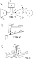
Fig. 1 is a schematic diagram of a gas turbine engine with a compressor, a combustor, a turbine, an exhaust diffuser, and a load. -
Fig. 2 is a sectional view of a portion of an exhaust diffuser of the gas turbine engine ofFig. 1 . -
Fig. 3 is a sectional view of an outer forward seal system of an exhaust diffuser as may be described herein. - Referring now to the drawings, in which like numerals refer to like elements throughout the several views,
Fig. 1 shows a schematic view ofgas turbine engine 10 as may be used herein. Thegas turbine engine 10 may include acompressor 15. Thecompressor 15 compresses an incoming flow ofair 20. Thecompressor 15 delivers the compressed flow ofair 20 to acombustor 25. Thecombustor 25 mixes the compressed flow ofair 20 with a pressurized flow offuel 30 and ignites the mixture to create a flow ofcombustion gases 35. Although only asingle combustor 25 is shown, thegas turbine engine 10 may include any number ofcombustors 25 configured in a circumferential array and the like. The flow ofcombustion gases 35 is in turn delivered to aturbine 40. The flow ofcombustion gases 35 drives theturbine 40 so as to produce mechanical work. The mechanical work produced in theturbine 40 drives thecompressor 15 via ashaft 45 and anexternal load 50 such as an electrical generator and the like. - The
gas turbine engine 10 may use natural gas, various types of syngas, liquid fuels, and/or other types of fuels and blends thereof. Thegas turbine engine 10 may be any one of a number of different gas turbine engines offered by General Electric Company of Schenectady, New York, including, but not limited to, those such as a 7 or a 9 series heavy duty gas turbine engine and the like. Thegas turbine engine 10 may have different configurations and may use other types of components. Other types of gas turbine engines also may be used herein. Multiple gas turbine engines, other types of turbines, and other types of power generation equipment also may be used herein together. - As is shown in
Figs. 1 and 2 , thegas turbine engine 10 also may include anexhaust diffuser 55. Theexhaust diffuser 55 may be positioned downstream of and in communication with theturbine 40. As described above, theexhaust diffuser 55 may include a number ofstruts 60 mounted on ahub 65 and enclosed within anouter casing 70. Thestruts 50 serve to hold thehub 65 and thecasing 70 in a fixed relationship to one another. Theexhaust diffuser 55 may turn the flow of thecombustion gases 35 in a radial direction. - The
exhaust diffuser 55 may include anouter diffuser section 75 attached to thecasing 70 so as to define a continuous flow path for thehot combustion gasses 35. Theouter diffuser section 75 may include aforward portion 80 positioned about the exit of theturbine 40. Theforward portion 80 may include an outer forward seal 85 extending towards thecasing 70. The outer forward seal 85 may include aflexible seal member 87. Theflexible seal member 87 may be positioned in aradial slot 90 formed by a number offlanges 92 extending from a skin 95 of theforward portion 80 of theouter diffuser section 75. As described above, theexhaust diffuser 55 may experience out of round conditions, particularly about theouter diffuser section 75 given the proximity to the exit of theturbine 40. -
Fig. 3 shows a portion of anexhaust diffuser 100 as may be described herein. In this example, theexhaust diffuser 100 may be segmented with two ormore segments 105. Theexhaust diffuser 100 may include anouter diffuser section 110 with aforward portion 120 positioned about the exit of theturbine 40. Theouter diffuser section 110 may include an outerforward seal system 130 extending about askin 140 of theforward portion 120. Instead of theslot 90 formed by theflanges 92 extending from the skin 95 as described above, theexhaust diffuser 100 described herein includes aseal base 150. Theseal base 150 may be detachable from theskin 140 of theforward portion 120. Theseal base 150 may include aradial slot 160 formed between a pair offlanges 170. Aflexible seal member 180 may be positioned and secured within theradial slot 160. Theseal base 150 and the components thereof may have any suitable size, shape, or configuration. - The
seal base 150 may be positioned in aseal pocket 190 formed within theskin 140 of theforward portion 120. Theseal pocket 190 may have any suitable size, shape, or configuration. Theseal base 150 may have an axially extendinghook 200 that may mate with anaxially extending slot 210 within the seal pocket 190 (or vice versa). Theforward portion 120 may have achannel 230 extending therein opening on aflow side 240 thereof and extending to theseal pocket 190. Theseal base 150 may be secured in place via adowel 220 extending through thechannel 230 of theforward portion 120. Other types of locking mechanisms may be used herein. - In use, the
seal base 150 may be positioned within theseal pocket 190 and secured via thedowel 220 extending through thechannel 230 from theflow side 240 of theforward portion 120. The mating of theaxially extending hook 200 theseal base 150 and theaxially extending slot 210 of theseal pocket 190 effectively locks theseal base 150 into position both radially and axially but largely decoupled in the hoop direction. The outerforward seal system 130 thus effectively reduces the radial height of theforward portion 120 so as to reduce the radial stiffness of theoverall exhaust diffuser 100. As a result, overall out of round conditions may be reduced while maintaining good sealing effectiveness. - The
exhaust diffuser 100 described herein thus splits the sealing function and the flow path forming function. Such a split may allow large relative deflection compensation between the static frame and the thermally growingexhaust diffuser 100. Specifically, the outerforward seal system 130 may minimized out of round conditions with reduced stress on theskin 140 of theforward portion 120 while maintaining good seal efficiency. Theexhaust diffuser 100 with the outerforward seal system 130 thus provides good sealing performance such that a smaller blower may be used to provide cooling/sealing air. Moreover, an improved circular shape given a reduction in out of round conditions may provide improved diffuser performance at the turbine exit with smaller separation in high flow conditions. The lower profile of theexhaust diffuser 100 also may create reduced stresses for a more robust performance with a reduction in maintenance. - It should be apparent that the foregoing relates only to certain embodiments of the present application and the resultant patent. Numerous changes and modifications may be made herein by one of ordinary skill in the art without departing from the general spirit and scope of the invention as defined by the following claims and the equivalents thereof.
PARTS LIST: 10 gas turbine engine 92 flanges 15 compressor 95 skin 20 air 100 exhaust diffuser 25 combustor 105 segments 30 fuel 110 outer diffuser section 35 combustion gases 120 forward portion 40 turbine 130 outer forward seal system 45 shaft 140 skin 50 load 150 seal base 55 exhaust diffuser 160 radial slot 60 struts 170 flanges 65 hub 180 seal member 70 outer casing 190 pocket 75 outer diffuser section 200 hook 80 forward portion 210 slot 85 outer forward seal system 220 dowel 87 flexible seal member 230 channel 90 radial slot 240 flow side
Claims (20)
- An exhaust diffuser, comprising:an outer diffuser section;the outer diffuser section comprising a forward portion; andan outer forward seal system positioned on the forward portion;the outer forward seal system comprising a seal base removably positioned in a seal pocket.
- The exhaust diffuser of claim 1, wherein the seal base comprises a pair of flanges defining a radial slot.
- The exhaust diffuser of claim 2, wherein the seal base comprises a seal member position within the radial slot.
- The exhaust diffuser of claim 3, wherein the seal member extends towards a casing.
- The exhaust diffuser of claim 3, wherein the seal member comprises a flexible seal.
- The exhaust diffuser of claim 1, wherein the seal base comprises a hook.
- The exhaust diffuser of claim 6, wherein the seal pocket comprises a slot to accommodate the hook therein.
- The exhaust diffuser of claim 7, wherein the forward portion comprises a flow side.
- The exhaust diffuser of claim 8, wherein the forward portion comprises a channel therein extending from the flow side.
- The exhaust diffuser of claim 9, wherein the forward portion comprises a dowel removably positioned within the channel and extending to the slot.
- The exhaust diffuser of claim 1, wherein the forward portion comprises a skin facing a flow of combustion gases.
- The exhaust diffuser of claim 11, wherein the seal pocket is positioned on the forward portion on an opposite side of the skin facing the flow of combustion gases.
- The exhaust diffuser of claim 1, wherein the exhaust diffuser comprises a plurality of segments.
- The exhaust diffuser of claim 1, wherein the forward portion faces a turbine.
- A method of operating an exhaust diffuser to limit out of round conditions, comprising:positioning a seal base in a seal pocket of a forward portion of the exhaust diffuser;locking the seal base into place via a channel extending through the forward portion from a flow side thereof; andflowing combustion gases past the forward portion on the flow side thereof.
- An exhaust diffuser, comprising:an outer diffuser section;the outer diffuser section comprising a forward portion; andan outer forward seal system positioned on the forward portion;the outer forward seal system comprising a seal base with a seal member; andthe outer forward seal system comprising a seal pocket formed within the forward portion with the seal member removably positioned therein and secured via a dowel extending through the forward portion.
- The exhaust diffuser of claim 16, wherein the seal base comprises a pair of flanges defining a radial slot.
- The exhaust diffuser of claim 16, wherein the seal base comprises a hook and wherein the seal pocket comprises a slot to accommodate the hook therein.
- The exhaust diffuser of claim 16, wherein the forward portion comprises a flow side.
- The exhaust diffuser of claim 19, wherein the forward portion comprises a channel therein extending from the flow side with the dowel removably positioned therein.
Priority Applications (5)
| Application Number | Priority Date | Filing Date | Title |
|---|---|---|---|
| EP17461583.1A EP3441578B1 (en) | 2017-08-11 | 2017-08-11 | Turbine exhaust diffuser |
| US16/029,708 US11215085B2 (en) | 2017-08-11 | 2018-07-09 | Turbine exhaust diffuser |
| KR1020180090650A KR102604517B1 (en) | 2017-08-11 | 2018-08-03 | Turbine exhaust diffuser |
| JP2018147314A JP7171297B2 (en) | 2017-08-11 | 2018-08-06 | turbine exhaust diffuser |
| CN201810910959.7A CN109386320A (en) | 2017-08-11 | 2018-08-10 | Turbine exhaust diffuser |
Applications Claiming Priority (1)
| Application Number | Priority Date | Filing Date | Title |
|---|---|---|---|
| EP17461583.1A EP3441578B1 (en) | 2017-08-11 | 2017-08-11 | Turbine exhaust diffuser |
Publications (2)
| Publication Number | Publication Date |
|---|---|
| EP3441578A1 true EP3441578A1 (en) | 2019-02-13 |
| EP3441578B1 EP3441578B1 (en) | 2021-03-03 |
Family
ID=59631708
Family Applications (1)
| Application Number | Title | Priority Date | Filing Date |
|---|---|---|---|
| EP17461583.1A Active EP3441578B1 (en) | 2017-08-11 | 2017-08-11 | Turbine exhaust diffuser |
Country Status (5)
| Country | Link |
|---|---|
| US (1) | US11215085B2 (en) |
| EP (1) | EP3441578B1 (en) |
| JP (1) | JP7171297B2 (en) |
| KR (1) | KR102604517B1 (en) |
| CN (1) | CN109386320A (en) |
Families Citing this family (1)
| Publication number | Priority date | Publication date | Assignee | Title |
|---|---|---|---|---|
| JP2025142836A (en) | 2024-03-18 | 2025-10-01 | 三菱重工業株式会社 | Exhaust equipment and gas turbine equipped with same |
Citations (4)
| Publication number | Priority date | Publication date | Assignee | Title |
|---|---|---|---|---|
| US5104286A (en) * | 1991-02-08 | 1992-04-14 | Westinghouse Electric Corp. | Recirculation seal for a gas turbine exhaust diffuser |
| EP0589215A1 (en) * | 1992-09-25 | 1994-03-30 | Asea Brown Boveri Ag | Gasturbine with exhaust casing and exhaust duct |
| US6065756A (en) * | 1997-12-10 | 2000-05-23 | General Electric Co. | Flex seal for gas turbine expansion joints |
| WO2014068355A1 (en) * | 2012-10-30 | 2014-05-08 | General Electric Company | Gas turbine engine exhaust system and corresponding method for accessing turbine buckets |
Family Cites Families (9)
| Publication number | Priority date | Publication date | Assignee | Title |
|---|---|---|---|---|
| EP0947667B1 (en) * | 1998-04-01 | 2004-12-15 | Mitsubishi Heavy Industries, Ltd. | Seal structure for a gas turbine |
| JP4256592B2 (en) * | 1999-02-10 | 2009-04-22 | ゼネラル・エレクトリック・カンパニイ | Flexible seal for gas turbine expansion joint |
| US8157509B2 (en) * | 2007-08-23 | 2012-04-17 | General Electric Company | Method, system and apparatus for turbine diffuser sealing |
| CN103557035B (en) * | 2008-02-27 | 2015-04-29 | 三菱日立电力系统株式会社 | Connection structure of exhaust chamber, support structure of turbine, and gas turbine |
| US20120034064A1 (en) * | 2010-08-06 | 2012-02-09 | General Electric Company | Contoured axial-radial exhaust diffuser |
| US20130033008A1 (en) * | 2011-08-03 | 2013-02-07 | General Electric Company | Outward bristle brush seal design for gas turbine application |
| US9650919B2 (en) * | 2014-08-04 | 2017-05-16 | Siemens Energy, Inc. | Moveable sealing arrangement for a gas turbine diffuser gap |
| US9664067B2 (en) * | 2014-10-10 | 2017-05-30 | General Electric Company | Seal retaining assembly |
| US20170211407A1 (en) * | 2016-01-21 | 2017-07-27 | General Electric Company | Flow alignment devices to improve diffuser performance |
-
2017
- 2017-08-11 EP EP17461583.1A patent/EP3441578B1/en active Active
-
2018
- 2018-07-09 US US16/029,708 patent/US11215085B2/en active Active
- 2018-08-03 KR KR1020180090650A patent/KR102604517B1/en active Active
- 2018-08-06 JP JP2018147314A patent/JP7171297B2/en active Active
- 2018-08-10 CN CN201810910959.7A patent/CN109386320A/en active Pending
Patent Citations (4)
| Publication number | Priority date | Publication date | Assignee | Title |
|---|---|---|---|---|
| US5104286A (en) * | 1991-02-08 | 1992-04-14 | Westinghouse Electric Corp. | Recirculation seal for a gas turbine exhaust diffuser |
| EP0589215A1 (en) * | 1992-09-25 | 1994-03-30 | Asea Brown Boveri Ag | Gasturbine with exhaust casing and exhaust duct |
| US6065756A (en) * | 1997-12-10 | 2000-05-23 | General Electric Co. | Flex seal for gas turbine expansion joints |
| WO2014068355A1 (en) * | 2012-10-30 | 2014-05-08 | General Electric Company | Gas turbine engine exhaust system and corresponding method for accessing turbine buckets |
Also Published As
| Publication number | Publication date |
|---|---|
| KR102604517B1 (en) | 2023-11-20 |
| KR20190017658A (en) | 2019-02-20 |
| EP3441578B1 (en) | 2021-03-03 |
| JP2019060336A (en) | 2019-04-18 |
| JP7171297B2 (en) | 2022-11-15 |
| CN109386320A (en) | 2019-02-26 |
| US11215085B2 (en) | 2022-01-04 |
| US20190048745A1 (en) | 2019-02-14 |
Similar Documents
| Publication | Publication Date | Title |
|---|---|---|
| EP2430297B1 (en) | Turbine engine with a structural attachment system for transition duct outlet | |
| US20100303608A1 (en) | Two-shaft gas turbine | |
| US9482107B2 (en) | Gas turbine nozzle arrangement and gas turbine | |
| US9206742B2 (en) | Passages to facilitate a secondary flow between components | |
| US9476317B2 (en) | Forward step honeycomb seal for turbine shroud | |
| US20130170977A1 (en) | Gas Turbine Nozzle with a Flow Groove | |
| US20130200571A1 (en) | Seal mechanism for use with turbine rotor | |
| US9850780B2 (en) | Plate for directing flow and film cooling of components | |
| EP2613013B1 (en) | Stage and turbine of a gas turbine engine | |
| US20140245750A1 (en) | Circumferentially retained fairing | |
| EP3450851B1 (en) | Transition duct for a gas turbine can combustor and gas turbine comprising such a transition duct | |
| EP3421726B1 (en) | Picture frame for connecting a can combustor to a turbine in a gas turbine and gas turbine comprising a picture frame | |
| US9011078B2 (en) | Turbine vane seal carrier with slots for cooling and assembly | |
| US11008869B2 (en) | Belly band seals | |
| US9470098B2 (en) | Axial compressor and method for controlling stage-to-stage leakage therein | |
| US11215085B2 (en) | Turbine exhaust diffuser | |
| RU2614892C2 (en) | Turbine nozzle blade inner platform and turbine nozzle blade (versions) | |
| US20130084160A1 (en) | Turbine Shroud Impingement System with Bellows | |
| US9528392B2 (en) | System for supporting a turbine nozzle | |
| US20130186103A1 (en) | Near flow path seal for a turbomachine | |
| US20230243304A1 (en) | Inducer seal with integrated inducer slots | |
| EP3249182B1 (en) | Radial exhaust diffuser | |
| EP3159497B1 (en) | System and method for wheel space temperature management | |
| US20180230838A1 (en) | Seal pressurization in box shroud | |
| GB2415017A (en) | Heat shield for attachment to a casing of a gas turbine engine |
Legal Events
| Date | Code | Title | Description |
|---|---|---|---|
| PUAI | Public reference made under article 153(3) epc to a published international application that has entered the european phase |
Free format text: ORIGINAL CODE: 0009012 |
|
| STAA | Information on the status of an ep patent application or granted ep patent |
Free format text: STATUS: THE APPLICATION HAS BEEN PUBLISHED |
|
| AK | Designated contracting states |
Kind code of ref document: A1 Designated state(s): AL AT BE BG CH CY CZ DE DK EE ES FI FR GB GR HR HU IE IS IT LI LT LU LV MC MK MT NL NO PL PT RO RS SE SI SK SM TR |
|
| AX | Request for extension of the european patent |
Extension state: BA ME |
|
| STAA | Information on the status of an ep patent application or granted ep patent |
Free format text: STATUS: REQUEST FOR EXAMINATION WAS MADE |
|
| 17P | Request for examination filed |
Effective date: 20190809 |
|
| RBV | Designated contracting states (corrected) |
Designated state(s): AL AT BE BG CH CY CZ DE DK EE ES FI FR GB GR HR HU IE IS IT LI LT LU LV MC MK MT NL NO PL PT RO RS SE SI SK SM TR |
|
| STAA | Information on the status of an ep patent application or granted ep patent |
Free format text: STATUS: EXAMINATION IS IN PROGRESS |
|
| 17Q | First examination report despatched |
Effective date: 20200227 |
|
| REG | Reference to a national code |
Ref country code: DE Ref legal event code: R079 Ref document number: 602017033740 Country of ref document: DE Free format text: PREVIOUS MAIN CLASS: F01D0025240000 Ipc: F01D0011000000 |
|
| RIC1 | Information provided on ipc code assigned before grant |
Ipc: F01D 25/30 20060101ALI20200817BHEP Ipc: F01D 25/24 20060101ALI20200817BHEP Ipc: F01D 11/00 20060101AFI20200817BHEP |
|
| GRAP | Despatch of communication of intention to grant a patent |
Free format text: ORIGINAL CODE: EPIDOSNIGR1 |
|
| STAA | Information on the status of an ep patent application or granted ep patent |
Free format text: STATUS: GRANT OF PATENT IS INTENDED |
|
| INTG | Intention to grant announced |
Effective date: 20201006 |
|
| GRAS | Grant fee paid |
Free format text: ORIGINAL CODE: EPIDOSNIGR3 |
|
| GRAA | (expected) grant |
Free format text: ORIGINAL CODE: 0009210 |
|
| STAA | Information on the status of an ep patent application or granted ep patent |
Free format text: STATUS: THE PATENT HAS BEEN GRANTED |
|
| AK | Designated contracting states |
Kind code of ref document: B1 Designated state(s): AL AT BE BG CH CY CZ DE DK EE ES FI FR GB GR HR HU IE IS IT LI LT LU LV MC MK MT NL NO PL PT RO RS SE SI SK SM TR |
|
| REG | Reference to a national code |
Ref country code: GB Ref legal event code: FG4D |
|
| REG | Reference to a national code |
Ref country code: AT Ref legal event code: REF Ref document number: 1367419 Country of ref document: AT Kind code of ref document: T Effective date: 20210315 Ref country code: CH Ref legal event code: EP |
|
| REG | Reference to a national code |
Ref country code: DE Ref legal event code: R096 Ref document number: 602017033740 Country of ref document: DE |
|
| REG | Reference to a national code |
Ref country code: IE Ref legal event code: FG4D |
|
| REG | Reference to a national code |
Ref country code: LT Ref legal event code: MG9D |
|
| PG25 | Lapsed in a contracting state [announced via postgrant information from national office to epo] |
Ref country code: BG Free format text: LAPSE BECAUSE OF FAILURE TO SUBMIT A TRANSLATION OF THE DESCRIPTION OR TO PAY THE FEE WITHIN THE PRESCRIBED TIME-LIMIT Effective date: 20210603 Ref country code: LT Free format text: LAPSE BECAUSE OF FAILURE TO SUBMIT A TRANSLATION OF THE DESCRIPTION OR TO PAY THE FEE WITHIN THE PRESCRIBED TIME-LIMIT Effective date: 20210303 Ref country code: FI Free format text: LAPSE BECAUSE OF FAILURE TO SUBMIT A TRANSLATION OF THE DESCRIPTION OR TO PAY THE FEE WITHIN THE PRESCRIBED TIME-LIMIT Effective date: 20210303 Ref country code: GR Free format text: LAPSE BECAUSE OF FAILURE TO SUBMIT A TRANSLATION OF THE DESCRIPTION OR TO PAY THE FEE WITHIN THE PRESCRIBED TIME-LIMIT Effective date: 20210604 Ref country code: HR Free format text: LAPSE BECAUSE OF FAILURE TO SUBMIT A TRANSLATION OF THE DESCRIPTION OR TO PAY THE FEE WITHIN THE PRESCRIBED TIME-LIMIT Effective date: 20210303 Ref country code: NO Free format text: LAPSE BECAUSE OF FAILURE TO SUBMIT A TRANSLATION OF THE DESCRIPTION OR TO PAY THE FEE WITHIN THE PRESCRIBED TIME-LIMIT Effective date: 20210603 |
|
| REG | Reference to a national code |
Ref country code: NL Ref legal event code: MP Effective date: 20210303 |
|
| REG | Reference to a national code |
Ref country code: AT Ref legal event code: MK05 Ref document number: 1367419 Country of ref document: AT Kind code of ref document: T Effective date: 20210303 |
|
| PG25 | Lapsed in a contracting state [announced via postgrant information from national office to epo] |
Ref country code: RS Free format text: LAPSE BECAUSE OF FAILURE TO SUBMIT A TRANSLATION OF THE DESCRIPTION OR TO PAY THE FEE WITHIN THE PRESCRIBED TIME-LIMIT Effective date: 20210303 Ref country code: LV Free format text: LAPSE BECAUSE OF FAILURE TO SUBMIT A TRANSLATION OF THE DESCRIPTION OR TO PAY THE FEE WITHIN THE PRESCRIBED TIME-LIMIT Effective date: 20210303 Ref country code: PL Free format text: LAPSE BECAUSE OF FAILURE TO SUBMIT A TRANSLATION OF THE DESCRIPTION OR TO PAY THE FEE WITHIN THE PRESCRIBED TIME-LIMIT Effective date: 20210303 Ref country code: SE Free format text: LAPSE BECAUSE OF FAILURE TO SUBMIT A TRANSLATION OF THE DESCRIPTION OR TO PAY THE FEE WITHIN THE PRESCRIBED TIME-LIMIT Effective date: 20210303 |
|
| PG25 | Lapsed in a contracting state [announced via postgrant information from national office to epo] |
Ref country code: NL Free format text: LAPSE BECAUSE OF FAILURE TO SUBMIT A TRANSLATION OF THE DESCRIPTION OR TO PAY THE FEE WITHIN THE PRESCRIBED TIME-LIMIT Effective date: 20210303 |
|
| PG25 | Lapsed in a contracting state [announced via postgrant information from national office to epo] |
Ref country code: EE Free format text: LAPSE BECAUSE OF FAILURE TO SUBMIT A TRANSLATION OF THE DESCRIPTION OR TO PAY THE FEE WITHIN THE PRESCRIBED TIME-LIMIT Effective date: 20210303 Ref country code: CZ Free format text: LAPSE BECAUSE OF FAILURE TO SUBMIT A TRANSLATION OF THE DESCRIPTION OR TO PAY THE FEE WITHIN THE PRESCRIBED TIME-LIMIT Effective date: 20210303 Ref country code: SM Free format text: LAPSE BECAUSE OF FAILURE TO SUBMIT A TRANSLATION OF THE DESCRIPTION OR TO PAY THE FEE WITHIN THE PRESCRIBED TIME-LIMIT Effective date: 20210303 Ref country code: AT Free format text: LAPSE BECAUSE OF FAILURE TO SUBMIT A TRANSLATION OF THE DESCRIPTION OR TO PAY THE FEE WITHIN THE PRESCRIBED TIME-LIMIT Effective date: 20210303 |
|
| PG25 | Lapsed in a contracting state [announced via postgrant information from national office to epo] |
Ref country code: RO Free format text: LAPSE BECAUSE OF FAILURE TO SUBMIT A TRANSLATION OF THE DESCRIPTION OR TO PAY THE FEE WITHIN THE PRESCRIBED TIME-LIMIT Effective date: 20210303 Ref country code: SK Free format text: LAPSE BECAUSE OF FAILURE TO SUBMIT A TRANSLATION OF THE DESCRIPTION OR TO PAY THE FEE WITHIN THE PRESCRIBED TIME-LIMIT Effective date: 20210303 Ref country code: PT Free format text: LAPSE BECAUSE OF FAILURE TO SUBMIT A TRANSLATION OF THE DESCRIPTION OR TO PAY THE FEE WITHIN THE PRESCRIBED TIME-LIMIT Effective date: 20210705 Ref country code: IS Free format text: LAPSE BECAUSE OF FAILURE TO SUBMIT A TRANSLATION OF THE DESCRIPTION OR TO PAY THE FEE WITHIN THE PRESCRIBED TIME-LIMIT Effective date: 20210703 |
|
| REG | Reference to a national code |
Ref country code: DE Ref legal event code: R097 Ref document number: 602017033740 Country of ref document: DE |
|
| PLBE | No opposition filed within time limit |
Free format text: ORIGINAL CODE: 0009261 |
|
| STAA | Information on the status of an ep patent application or granted ep patent |
Free format text: STATUS: NO OPPOSITION FILED WITHIN TIME LIMIT |
|
| PG25 | Lapsed in a contracting state [announced via postgrant information from national office to epo] |
Ref country code: DK Free format text: LAPSE BECAUSE OF FAILURE TO SUBMIT A TRANSLATION OF THE DESCRIPTION OR TO PAY THE FEE WITHIN THE PRESCRIBED TIME-LIMIT Effective date: 20210303 Ref country code: AL Free format text: LAPSE BECAUSE OF FAILURE TO SUBMIT A TRANSLATION OF THE DESCRIPTION OR TO PAY THE FEE WITHIN THE PRESCRIBED TIME-LIMIT Effective date: 20210303 Ref country code: ES Free format text: LAPSE BECAUSE OF FAILURE TO SUBMIT A TRANSLATION OF THE DESCRIPTION OR TO PAY THE FEE WITHIN THE PRESCRIBED TIME-LIMIT Effective date: 20210303 |
|
| 26N | No opposition filed |
Effective date: 20211206 |
|
| PG25 | Lapsed in a contracting state [announced via postgrant information from national office to epo] |
Ref country code: SI Free format text: LAPSE BECAUSE OF FAILURE TO SUBMIT A TRANSLATION OF THE DESCRIPTION OR TO PAY THE FEE WITHIN THE PRESCRIBED TIME-LIMIT Effective date: 20210303 |
|
| REG | Reference to a national code |
Ref country code: CH Ref legal event code: PL |
|
| PG25 | Lapsed in a contracting state [announced via postgrant information from national office to epo] |
Ref country code: MC Free format text: LAPSE BECAUSE OF FAILURE TO SUBMIT A TRANSLATION OF THE DESCRIPTION OR TO PAY THE FEE WITHIN THE PRESCRIBED TIME-LIMIT Effective date: 20210303 |
|
| REG | Reference to a national code |
Ref country code: BE Ref legal event code: MM Effective date: 20210831 |
|
| GBPC | Gb: european patent ceased through non-payment of renewal fee |
Effective date: 20210811 |
|
| PG25 | Lapsed in a contracting state [announced via postgrant information from national office to epo] |
Ref country code: LI Free format text: LAPSE BECAUSE OF NON-PAYMENT OF DUE FEES Effective date: 20210831 Ref country code: CH Free format text: LAPSE BECAUSE OF NON-PAYMENT OF DUE FEES Effective date: 20210831 |
|
| PG25 | Lapsed in a contracting state [announced via postgrant information from national office to epo] |
Ref country code: IS Free format text: LAPSE BECAUSE OF FAILURE TO SUBMIT A TRANSLATION OF THE DESCRIPTION OR TO PAY THE FEE WITHIN THE PRESCRIBED TIME-LIMIT Effective date: 20210703 Ref country code: LU Free format text: LAPSE BECAUSE OF NON-PAYMENT OF DUE FEES Effective date: 20210811 |
|
| PG25 | Lapsed in a contracting state [announced via postgrant information from national office to epo] |
Ref country code: IE Free format text: LAPSE BECAUSE OF NON-PAYMENT OF DUE FEES Effective date: 20210811 Ref country code: GB Free format text: LAPSE BECAUSE OF NON-PAYMENT OF DUE FEES Effective date: 20210811 Ref country code: FR Free format text: LAPSE BECAUSE OF NON-PAYMENT OF DUE FEES Effective date: 20210831 Ref country code: BE Free format text: LAPSE BECAUSE OF NON-PAYMENT OF DUE FEES Effective date: 20210831 |
|
| P01 | Opt-out of the competence of the unified patent court (upc) registered |
Effective date: 20230522 |
|
| PG25 | Lapsed in a contracting state [announced via postgrant information from national office to epo] |
Ref country code: CY Free format text: LAPSE BECAUSE OF FAILURE TO SUBMIT A TRANSLATION OF THE DESCRIPTION OR TO PAY THE FEE WITHIN THE PRESCRIBED TIME-LIMIT Effective date: 20210303 |
|
| PG25 | Lapsed in a contracting state [announced via postgrant information from national office to epo] |
Ref country code: HU Free format text: LAPSE BECAUSE OF FAILURE TO SUBMIT A TRANSLATION OF THE DESCRIPTION OR TO PAY THE FEE WITHIN THE PRESCRIBED TIME-LIMIT; INVALID AB INITIO Effective date: 20170811 |
|
| REG | Reference to a national code |
Ref country code: DE Ref legal event code: R081 Ref document number: 602017033740 Country of ref document: DE Owner name: GENERAL ELECTRIC TECHNOLOGY GMBH, CH Free format text: FORMER OWNER: GENERAL ELECTRIC COMPANY, SCHENECTADY, NY, US |
|
| PG25 | Lapsed in a contracting state [announced via postgrant information from national office to epo] |
Ref country code: MK Free format text: LAPSE BECAUSE OF FAILURE TO SUBMIT A TRANSLATION OF THE DESCRIPTION OR TO PAY THE FEE WITHIN THE PRESCRIBED TIME-LIMIT Effective date: 20210303 |
|
| PG25 | Lapsed in a contracting state [announced via postgrant information from national office to epo] |
Ref country code: TR Free format text: LAPSE BECAUSE OF FAILURE TO SUBMIT A TRANSLATION OF THE DESCRIPTION OR TO PAY THE FEE WITHIN THE PRESCRIBED TIME-LIMIT Effective date: 20210303 |
|
| PG25 | Lapsed in a contracting state [announced via postgrant information from national office to epo] |
Ref country code: MT Free format text: LAPSE BECAUSE OF FAILURE TO SUBMIT A TRANSLATION OF THE DESCRIPTION OR TO PAY THE FEE WITHIN THE PRESCRIBED TIME-LIMIT Effective date: 20210303 |
|
| PGFP | Annual fee paid to national office [announced via postgrant information from national office to epo] |
Ref country code: DE Payment date: 20250724 Year of fee payment: 9 |
|
| PGFP | Annual fee paid to national office [announced via postgrant information from national office to epo] |
Ref country code: IT Payment date: 20250723 Year of fee payment: 9 |