EP3441563A1 - Rotor für eine turbomaschine - Google Patents
Rotor für eine turbomaschine Download PDFInfo
- Publication number
- EP3441563A1 EP3441563A1 EP18187801.8A EP18187801A EP3441563A1 EP 3441563 A1 EP3441563 A1 EP 3441563A1 EP 18187801 A EP18187801 A EP 18187801A EP 3441563 A1 EP3441563 A1 EP 3441563A1
- Authority
- EP
- European Patent Office
- Prior art keywords
- rotor
- stage
- hole
- section
- disk
- Prior art date
- Legal status (The legal status is an assumption and is not a legal conclusion. Google has not performed a legal analysis and makes no representation as to the accuracy of the status listed.)
- Granted
Links
Images

Classifications
-
- F—MECHANICAL ENGINEERING; LIGHTING; HEATING; WEAPONS; BLASTING
- F01—MACHINES OR ENGINES IN GENERAL; ENGINE PLANTS IN GENERAL; STEAM ENGINES
- F01D—NON-POSITIVE DISPLACEMENT MACHINES OR ENGINES, e.g. STEAM TURBINES
- F01D5/00—Blades; Blade-carrying members; Heating, heat-insulating, cooling or antivibration means on the blades or the members
- F01D5/02—Blade-carrying members, e.g. rotors
- F01D5/06—Rotors for more than one axial stage, e.g. of drum or multiple disc type; Details thereof, e.g. shafts, shaft connections
- F01D5/066—Connecting means for joining rotor-discs or rotor-elements together, e.g. by a central bolt, by clamps
-
- F—MECHANICAL ENGINEERING; LIGHTING; HEATING; WEAPONS; BLASTING
- F05—INDEXING SCHEMES RELATING TO ENGINES OR PUMPS IN VARIOUS SUBCLASSES OF CLASSES F01-F04
- F05D—INDEXING SCHEME FOR ASPECTS RELATING TO NON-POSITIVE-DISPLACEMENT MACHINES OR ENGINES, GAS-TURBINES OR JET-PROPULSION PLANTS
- F05D2220/00—Application
- F05D2220/30—Application in turbines
-
- F—MECHANICAL ENGINEERING; LIGHTING; HEATING; WEAPONS; BLASTING
- F05—INDEXING SCHEMES RELATING TO ENGINES OR PUMPS IN VARIOUS SUBCLASSES OF CLASSES F01-F04
- F05D—INDEXING SCHEME FOR ASPECTS RELATING TO NON-POSITIVE-DISPLACEMENT MACHINES OR ENGINES, GAS-TURBINES OR JET-PROPULSION PLANTS
- F05D2230/00—Manufacture
- F05D2230/60—Assembly methods
-
- F—MECHANICAL ENGINEERING; LIGHTING; HEATING; WEAPONS; BLASTING
- F05—INDEXING SCHEMES RELATING TO ENGINES OR PUMPS IN VARIOUS SUBCLASSES OF CLASSES F01-F04
- F05D—INDEXING SCHEME FOR ASPECTS RELATING TO NON-POSITIVE-DISPLACEMENT MACHINES OR ENGINES, GAS-TURBINES OR JET-PROPULSION PLANTS
- F05D2250/00—Geometry
- F05D2250/10—Two-dimensional
- F05D2250/14—Two-dimensional elliptical
-
- Y—GENERAL TAGGING OF NEW TECHNOLOGICAL DEVELOPMENTS; GENERAL TAGGING OF CROSS-SECTIONAL TECHNOLOGIES SPANNING OVER SEVERAL SECTIONS OF THE IPC; TECHNICAL SUBJECTS COVERED BY FORMER USPC CROSS-REFERENCE ART COLLECTIONS [XRACs] AND DIGESTS
- Y02—TECHNOLOGIES OR APPLICATIONS FOR MITIGATION OR ADAPTATION AGAINST CLIMATE CHANGE
- Y02T—CLIMATE CHANGE MITIGATION TECHNOLOGIES RELATED TO TRANSPORTATION
- Y02T50/00—Aeronautics or air transport
- Y02T50/60—Efficient propulsion technologies, e.g. for aircraft
Definitions
- the present invention relates to a rotor for a turbomachine, comprising at least two bladed, releasably interconnected rotor stages according to the preamble of claim 1.
- Rotors for turbomachinery known from the prior art have rotors with a plurality of rotor stages, wherein the rotor stages can be connected to one another in different ways. Flange connections are often used, with a rotor stage connected to a shaft being connected to further rotor stages by means of flanges. These compounds of the rotor stages are often subject to high loads due to the application. Both the voltage level and the voltage amplitudes can be lifetime-determining for the respective components.
- An object of the present invention is to propose a further rotor which at least reduces the said problems.
- a rotor for a turbomachine which has at least two bladed, releasably interconnected rotor stages.
- a first rotor stage is connected by means of a flange with a rotor disk of a second, adjacent rotor stage by means of at least one connecting element.
- the compound is in particular releasable, for example by means of a bolt connection.
- the rotor disk of the second rotor stage has a through-hole for connecting the two rotor stages.
- the connection has a connecting element, for example a bolt, a screw or the like, which can be passed or inserted through the through-bore.
- the through hole has a cross section, which is larger in the circumferential direction of the rotor disk than in the radial direction of the rotor disk.
- Inventive exemplary embodiments may have one or more of the following features.
- the through-hole has an elliptical cross-section, wherein the major axis of the elliptical cross-section in the circumferential direction of the rotor disk is larger with respect to the minor axis in the radial direction of the rotor disk.
- the elliptical shape is particularly advantageous.
- the through-hole has the shape of a long hole, in particular with a cross-sectional shape formed by two parallel linear or curved boundary lines in the circumferential direction and by two semi-circular boundary lines which connect the parallel boundary lines respectively.
- In the circumferential direction may refer in particular to the direction at the circumferential position of the center through hole in connection with a linear Stecke.
- the through hole has a different shape again, in particular their maximum dimension or extent in the circumferential direction is also greater than in the radial direction.
- a rotor stage includes a blade having a blade root, a rotor body, a rotor disk and, optionally, a rotor arm and a flange.
- the rotor arm may have at least one sealing tip for sealing against leakage flows.
- the rotor stage can be produced integrally, that is, in one-piece construction, for example as a casting or by means of a generative manufacturing process. Alternatively, the blade or the blades arranged over the circumference of the rotor body can be manufactured separately, which are then assembled together.
- adjacent rotor stages are successively arranged rotor stages in the flow direction of the turbomachine.
- a rotor may comprise 3, 5, 7, 9 or more rotor stages.
- One or more of the rotor stages of a rotor may be connected to a shaft of the turbomachine.
- the second and the last or penultimate rotor stage may be connected to the shaft of the turbomachine.
- the through-bore is arranged on the radially outer end region of the rotor disk at or before the transition to the rotor main body.
- a plurality of through bores can be arranged over the circumference of the rotor disk in order to achieve the most reliable and stable connection of the rotor stages.
- ten, twenty, forty, sixty or more through bores can be arranged over the circumference.
- the arrangement may be symmetrical or asymmetrical over the circumference.
- all or only a part of the through holes can be provided or fitted and mounted with securing elements.
- the flange of the first rotor stage is disposed at the axially downstream end of a rotor arm of the first rotor stage.
- the first and second rotor stage with the rotor arm and the flange form a so-called rotor drum.
- the rotor arm may have a radially outwardly directed passage opening for the outflow or centrifuging of fluid out of the rotor drum.
- a flange of the third rotor stage is disposed at the axially upstream end of a rotor arm of the third rotor stage, with respect to the flow direction of the turbomachine.
- a flange disposed at the downstream end of the rotor arm of the first rotor stage and a flange disposed at the upstream end of the rotor arm of the third rotor stage are mounted in an advantageous compact design with each other on the rotor disk of the second rotor stage and connected ,
- the first rotor stage is an upstream rotor stage of the rotor.
- a shape according to the invention namely with a greater extent in the circumferential direction than in the radial direction, in particular an elliptical shape, the through hole of the rotor rotor of the second rotor stage, which is connected to the first rotor stage by means of the fuse element, advantageously occurring high voltage levels and voltage amplitudes in Reduce the area of the through hole and thus contribute, for example, to an increased life.
- the second rotor stage in this embodiment is often connected to the shaft of the turbomachine and often subjected to high loads.
- a high operating temperature in the region of the through-bore of the rotor disk of the second rotor stage can also occur.
- the inventive shape of the through hole of the rotor disk of the second rotor stage can also contribute in this case to a lower damage to the rotor disk and / or a longer life of the component.
- the connecting element of the second rotor stage is connected to the flange of the third rotor stage.
- the connecting element can connect the rotor disk of the second rotor stage and the flange of the third rotor stage.
- the flange of the first rotor stage can be connected to the rotor disk of the second rotor stage and the flange of the third rotor stage.
- the cross-sectional dimension of the through-bore (11) in the circumferential direction (u) of the rotor disk (25) is at most 20%, in particular at most 15%, more particularly at most 10%, further in particular at most 5% greater than the cross-sectional dimension of the through-bore (11 ) in the radial direction (r) of the rotor disk (25).
- the major axis of the elliptical cross section which is aligned in the circumferential direction of the rotor disk, is at most 20% greater than the minor axis of the elliptical cross section, which is aligned in the radial direction of the rotor disk.
- the length or extent of the minor axis of the elliptical cross section of the through hole for example 9 mm, so that the length or extent of the main axis is a maximum of 10.8 mm.
- the length or extent of the minor axis can be adapted.
- the major axis of the elliptical cross section, which is aligned in the circumferential direction of the rotor disk is at most 15% greater than the minor axis of the elliptical cross section, which is aligned in the radial direction of the rotor disk.
- the major axis of the elliptical cross section, which is aligned in the circumferential direction of the rotor disk is at most 10% greater than the minor axis of the elliptical cross section, which is aligned in the radial direction of the rotor disk.
- the major axis of the elliptical cross section, which is aligned in the circumferential direction of the rotor disk, is at most 5% greater than the minor axis of the elliptical cross section, which is aligned in the radial direction of the rotor disk.
- the length or extension of the minor axis of the elliptical cross section of the through-bore is at most 10% greater than the diameter of a shank of the connecting element in the through-bore.
- the connecting element may be a bolt.
- the through hole can be designed as a circular bore with a clearance fit. Subsequently, this circular bore can be expanded to an elliptical through-hole, for example by means of a spiral milling. This expansion may provide for a maximum expansion of the length or extension of the minor axis to an additional length of 10% with respect to the diameter of the previously performed circular bore.
- the circular bore could have a diameter of 9 mm. Then the length or extension of the minor axis can be limited to a maximum of 9.9 mm.
- the length or extension of the minor axis of the elliptical cross section of the through-bore is at most 5% greater than the diameter of a shank of the connecting element in the through-bore.
- the connecting element is a bolt with a bolt head and a securing element.
- the shank of the connecting element has a thread.
- the securing element may be a nut.
- the throughbore is surface treated.
- the surface of the through-hole can be improved by means of a surface treatment.
- An improvement of the surface can be quantified by means of a lower average surface roughness.
- a surface treatment may include, for example, blasting and / or deep-rolling and / or smooth-rolling.
- a surface treatment can advantageously increase the life of the component, in particular if the component is subject to high mechanical loads, for example high mechanical stress loads and / or high mechanical stress amplitudes.
- the surface of the through-bore has a center roughness of not more than 0.4 ⁇ m, in particular not more than 0.2 ⁇ m.
- the rotor is a rotor of a gas turbine stage, in particular a low-pressure turbine.
- the turbomachine is an axial gas turbine.
- the axial gas turbine is an aircraft engine.
- Some or all embodiments according to the invention may have one, several or all of the advantages mentioned above and / or below.
- the rotor according to the invention can advantageously at least reduce damage due to high mechanical stress levels and / or high mechanical stress amplitudes in a rotor stage by means of a through-hole for a securing element.
- the rotor according to the invention can reduce the material load in the rotor stage, in particular in the rotor disk, which has a through-hole for a securing element, due to the non-circular, in particular elliptical cross-section of the through-hole.
- the damage can be referred to as component damage.
- the rotor according to the invention can advantageously reduce the occurring mechanical stress amplitudes in the through-hole with a non-circular, in particular elliptical, cross-section with respect to a through-hole with a circular cross-section.
- the voltage amplitude at the surface of the through-hole for example in a load case, such as occurs in an aircraft engine, can be reduced from about 2000 MPa for a circular cross-section to about 1800 MPa for an elliptical cross-section.
- the rotor according to the invention can improve the so-called rotor characteristic value "LCF” (Low Cycle Fatigue), for example from an LCF of approximately 20000 c / s (cycles per second) for a rotor with a circular cross section of the throughbore to an LCF of about 25,000 c / s (cycles per second) in a rotor with an elliptical cross section of the through hole.
- LCF Low Cycle Fatigue
- the mechanical load of the through hole for connecting the rotor stages can advantageously be adapted such that the load in the region of the radially inner diameter of the through hole, in the region of the radially outer diameter of the through hole and in the region of the so-called spoke, ie in the range the circumferential surface of the through hole (see Fig. 2 ) is about the same.
- the through-bore has such an approximately equal load situation on the surfaces, the through-bore can be referred to as an at least approximately, optimally designed through-hole. Consequently, it is by means of the rotor according to the invention, at least approximately, optimally designed through-hole advantageously possible.
- Component damage may be defined such that a throughbore has a crack that emanates from the surface of the throughbore and continues into the material of the component.
- a component damage may have a technical crack with a crack depth of at least about 0.4 mm to 0.8 mm, these values are purely exemplary.
- Such fracture depths may occur in embodiments in which the rotor is part of an aircraft engine, in particular part of a low-pressure turbine in the aircraft engine.
- the aircraft engines can be examined with regard to such cracking at predetermined maintenance intervals.
- the maintenance intervals can be performed after a certain number of cycles of the component, which are determined, for example, after the successful flight movements of the aircraft engine.
- the movements of the aircraft can be determined on the basis of the take-offs and landings of an aircraft with the aircraft engine.
- a component damage can be used as a feature or as an indication of the life of a component.
- the crack depths given by way of example can thus at least influence the service life of the component.
- the rotor according to the invention can thus advantageously increase the service life of the rotor by means of the non-circular, in particular elliptical cross-section of the through-bore.
- the rotor according to the invention can advantageously at least reduce component damage and / or increase the service life of the rotor, in particular in low-pressure turbines and / or high-pressure turbines of aircraft engines.
- the rotor according to the invention can advantageously be reduced, the number of connecting elements for connecting rotor stages. Due to a reduced component load by means of a non-circular, in particular elliptical cross section of the through holes for connecting elements, a reduced number of connecting elements per rotor stage can lead to a lower weight of the rotor. On Lower weight can lead to cost savings, for example due to reduced fuel consumption of an aircraft engine.
- a permissible LCF value for example, a LCF value of 25000 c / s for a low-pressure turbine in an aircraft engine, without increasing the number of through holes and connecting elements per rotor disk.
- the LCF value of 25,000 c / s can be achieved, for example, by an elliptical cross-section of the through-holes.
- Fig. 1 shows a rotor 100 according to the invention for an axial turbomachine with three rotor stages 1, 3, 5, which are interconnected by means of a bolt 7.
- the second rotor stage 3 of the rotor 100 has a through hole 11 through the rotor disk 25 of the second rotor stage 3, through which the bolt shaft 13 of the bolt 7 has been passed or inserted.
- the cross-sectional shape of the through hole 11 is in Fig. 2 explained in more detail.
- a flange 17 of the first rotor stage 1 is arranged on the axially a downstream end region of the rotor arm 19.
- the rotor arm 19 further comprises sealing tips 21 for sealing a possible leakage flow between the rotor arm 19 and a vane (in Fig. 1 not shown).
- the bolt 7 has a bolt head 15 which bears against the flange 17 of the first rotor stage 1.
- the bolt head 15 continues to rest, purely by way of example, on the circumference of the bolt head 15 against a shoulder of the rotor arm 19. This concern can be used as anti-rotation when tightening the Connection of the three rotor stages 1, 3, 5 act.
- the bolt shank 9 purely by way of example has a thread on the pin shaft end (on the right in FIG Fig. 1 ), onto which a securing element, here by way of example a nut 23, is screwed.
- Other backup options eg. B. by means of a splint, are also possible.
- the third rotor stage 5 (in Fig. 1 right) is also connected by means of a flange 27 and the bolt 7 with the second rotor stage 3, and indirectly with the first rotor stage 1.
- the flange 27 of the third rotor stage 5 is arranged at the upstream front end (viewed in the flow direction 9) of the rotor arm 29.
- the second rotor stage 3 is connected to a shaft 33 of the axial turbomachine.
- This connection is not detailed here for reasons of clarity.
- the connection may be, for example, a keyway-groove connection.
- the first 1 and third 5 rotor stages of the rotor 100 according to the invention are also connected to the shaft 33.
- All three rotor stages 1, 3, 5 are bladed, thus have impeller blades 35, 37, 39 which are directed radially outward, with respect to the rotor base body 41, 43, 45.
- the through-bore 11 can have the same axial position through the rotor disk 25 and the blades 37 arranged on the rotor disk 25 and / or the through-bore 11 can be arranged in the axial extension region of the blades 37.
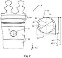
- Fig. 2 shows a section of the second rotor disk 3 of a rotor 100 according to the invention with a through hole 11 which has an elliptical cross section.
- the rotor disk 3 is with respect to the view of Fig. 1 turned 90 degrees into the drawing plane.
- the circumferential direction u points in Fig. 2 to the right, the axial direction a into the plane of the drawing.
- the rotor base body 43 is radially outward for connection to a blade root of the blade 37 (see Fig. 1 ) purely exemplarily formed in dovetail shape. Likewise, the entire impeller, so the blades 37 with blade roots, rotor base 43 and rotor disk 25 in integral construction (integrally) may be formed.
- the through-hole 11 has an elliptical cross-section.
- the major axis 49 of the elliptical cross-section is larger in the circumferential direction u relative to the minor axis 51, which is aligned in the radial direction r of the rotor disk 25.
- the length or extent of the main axis 49 may be referred to as spoke 59 (English: Spoke).
- the spoke can be called a "wheel.” be abbreviated.
- the outer diameter 55 with respect to the radial direction r or outer diameter can be abbreviated as "OD" (outer diameter)
- the inner diameter 57 or inner diameter can be abbreviated as "ID” (English: inner diameter).
- a round diameter 53 is shown in dashed lines, which would correspond to a pin bore without the elliptical cross section according to the invention.
- This pin bore would, for example, have a clearance fit relative to the pin shank diameter.
- Other fits or bore diameters for a pin bore would also be possible.
- the elliptical cross section can be produced for example in such a way that first a round through-hole is produced and then, for example by means of a spiral milling method, an elliptical widening takes place.
- the elliptical cross section 11 according to the invention advantageously enables a reduced material load of the rotor disk 25 in the region of the through bore 11.
- the (mechanical) stress level as well as the stress amplitude in the region of the through bore 11 can caused by the bolt 7, assume sizes that can lead to damage and thus to a reduced life of the component.
- the cross section of the through hole may have another non-circular and non-elliptical shape whose particular maximum dimension or extent in the circumferential direction is greater than in the radial direction, which also allows an improvement over a through hole with a circular cross-section.
Landscapes
- Engineering & Computer Science (AREA)
- Mechanical Engineering (AREA)
- General Engineering & Computer Science (AREA)
- Turbine Rotor Nozzle Sealing (AREA)
Abstract
Description
- Die vorliegende Erfindung betrifft einen Rotor für eine Turbomaschine, mit wenigstens zwei beschaufelten, lösbar miteinander verbundenen Rotorstufen gemäß dem Oberbegriff des Anspruchs 1.
- Aus dem Stand der Technik bekannte Rotoren für Turbomaschinen weisen Rotoren mit mehreren Rotorstufen auf, wobei die Rotorstufen auf unterschiedliche Art und Weise miteinander verbunden sein können. Oft werden Flanschverbindungen eingesetzt, wobei eine mit einer Welle verbundene Rotorstufe mit weiteren Rotorstufen mittels Flanschen verbunden werden. Diese Verbindungen der Rotorstufen sind einsatzbedingt oft hohen Belastungen ausgesetzt. Sowohl das Spannungsniveau als auch die Spannungsamplituden können lebensdauerbestimmend für die jeweiligen Bauteile sein.
- Eine Aufgabe der vorliegenden Erfindung ist es, einen weiteren Rotor vorzuschlagen, der die genannten Probleme zumindest verringert.
- Die erfindungsgemäße Aufgabe wird durch einen Rotor mit den Merkmalen des Anspruchs 1 gelöst.
- Erfindungsgemäß wird somit ein Rotor für eine Turbomaschine vorgeschlagen, der wenigstens zwei beschaufelte, lösbar miteinander verbundene Rotorstufen aufweist. Eine erste Rotorstufe ist mittels eines Flanschs mit einer Rotorscheibe einer zweiten, benachbarten Rotorstufe mittels wenigstens eines Verbindungselements verbunden. Die Verbindung ist insbesondere lösbar, beispielsweise mittels einer Bolzenverbindung. Die Rotorscheibe der zweiten Rotorstufe weist eine Durchgangsbohrung zum Verbinden der beiden Rotorstufen auf. Die Verbindung weist ein Verbindungselement auf, beispielsweise ein Bolzen, eine Schraube oder ähnliches, die durch die Durchgangsbohrung hindurchgeführt bzw. eingesteckt werden kann. Die Durchgangsbohrung weist einen Querschnitt auf, wobei der in Umfangsrichtung der Rotorscheibe größer als in Radialrichtung der Rotorscheibe ist.
- Vorteilhafte Weiterentwicklungen der vorliegenden Erfindung sind jeweils Gegenstand von Unteransprüchen und Ausführungsformen.
- Erfindungsgemäße beispielhafte Ausführungsformen können eines oder mehrere der im Folgenden genannten Merkmale aufweisen.
- In einigen erfindungsgemäßen Ausführungsformen weist die Durchgangsbohrung einen elliptischen Querschnitt auf, wobei die Hauptachse des elliptischen Querschnitts in Umfangsrichtung der Rotorscheibe größer gegenüber der Nebenachse in Radialrichtung der Rotorscheibe ist. Spannungstechnisch ist die Ellipsenform besonders vorteilhaft.
- In anderen erfindungsgemäßen Ausführungsformen hat die Durchgangsbohrung die Form eines Langlochs, insbesondere mit einer Querschnittsform, die durch zwei parallele lineare oder gekrümmte Grenzlinien in Umfangsrichtung sowie durch zwei halbkreisförmige Grenzlinien, welche die parallelen Grenzlinien jeweils verbinden, gebildet wird.
- "In Umfangsrichtung" kann sich im Zusammenhang mit einer linearen Stecke insbesondere auf die Richtung an der Umfangsposition des Zentrums Durchgangsbohrung beziehen.
- In wieder anderen erfindungsgemäßen Ausführungsformen hat die Durchgangsbohrung eine wieder andere Form, deren insbesondere maximale Abmessung bzw. Erstreckung in Umfangsrichtung ebenfalls größer ist als in Radialrichtung.
- In einigen erfindungsgemäßen Ausführungsformen umfasst eine Rotorstufe eine Schaufel mit einem Schaufelfuß, einen Rotorgrundkörper, eine Rotorscheibe und, optional, einen Rotorarm und einen Flansch. Der Rotorarm kann wenigstens eine Dichtspitze zum Abdichten gegen Leckageströmungen aufweisen. Die Rotorstufe kann integral hergestellt werden, das heißt in einstückiger Bauweise, beispielsweise als Gußteil oder mittels eines generativen Fertigungsverfahrens. Alternativ kann die Schaufel bzw. die über dem Umfang des Rotorgrundkörpers angeordneten Schaufeln separat hergestellt sein, die anschließend miteinander montiert werden.
- In einigen erfindungsgemäßen Ausführungsformen sind benachbarte Rotorstufen in Durchströmungsrichtung der Turbomaschine nacheinander angeordnete Rotorstufen. Ein Rotor kann beispielsweise 3, 5, 7, 9 oder mehr Rotorstufen umfassen. Eine oder mehrere der Rotorstufen eines Rotors können mit einer Welle der Turbomaschine verbunden sein. Beispielsweise kann die zweite und die letzte oder vorletzte Rotorstufe mit der Welle der Turbomaschine verbunden sein.
- In einigen erfindungsgemäßen Ausführungsformen ist die Durchgangsbohrung am radial äußeren Endbereich der Rotorscheibe am oder vor dem Übergang zum Rotorgrundkörper angeordnet. Über dem Umfang der Rotorscheibe können mehrere Durchgangsbohrungen angeordnet sein, um eine möglichst sichere und stabile Verbindung der Rotorstufen zu erreichen. Insbesondere bei einer als axiale Gasturbine, beispielsweise als Flugtriebwerk ausgeführte Turbomaschine, können zehn, zwanzig, vierzig, sechzig oder mehr Durchgangsbohrungen über dem Umfang angeordnet sein. Die Anordnung kann über dem Umfang symmetrisch oder unsymmetrisch sein. Zum Verbinden der Rotorstufen können alle oder nur ein Teil der Durchgangsbohrungen mit Sicherungselementen versehen bzw. bestückt und montiert werden. Wenn beispielsweise eine Festigkeitsanalyse, die experimentell oder mittels Simulation durchgeführt werden kann, als Ergebnis zeigt, dass nur ein Teil der Durchgangsbohrungen notwendigerweise montiert werden sollte, kann aus Gründen der Gewichtsreduzierung (dies kann einen geringeren Treibstoffverbrauch zur Folge haben und damit wirtschaftlicher sein) nur ein Teil Durchgangsbohrungen mit Sicherungselementen montiert werden. Gegebenenfalls kann aus Sicherheitsgründen die technisch notwendige Anzahl erhöht werden.
- In einigen erfindungsgemäßen Ausführungsformen ist der Flansch der ersten Rotorstufe, in Bezug auf die Durchströmungsrichtung der Turbomaschine, am axial stromab angeordneten Ende eines Rotorarms der ersten Rotorstufe angeordnet. In dieser Anordnung kann die erste und zweite Rotorstufe mit dem Rotorarm und dem Flansch eine sogenannte Rotortrommel ausbilden. Der Rotorarm kann eine nach radial außen gerichtete Durchgangsöffhung zum Abfließen bzw. Abschleudern von Fluid aus der Rotortrommel aufweisen.
- In einigen erfindungsgemäßen Ausführungsformen ist ein Flansch der dritten Rotorstufe am, in Bezug auf die Durchströmungsrichtung der Turbomaschine, axial stromauf angeordneten Ende eines Rotorarms der dritten Rotorstufe angeordnet ist. Somit kann ein Flansch, der am stromab angeordneten Ende des Rotorarms der ersten Rotorstufe angeordnet ist und ein Flansch, der am stromauf angeordneten Ende des Rotorarms der dritten Rotorstufe angeordnet ist, in einer vorteilhaft kompakten Bauweise miteinander an der Rotorscheibe der zweiten Rotorstufe montiert und verbunden werden. Zur Montage kann ein Sicherungselement alle drei Bauteile, also die Flansche der ersten und dritten Rotorstufe zusammen mit der Rotorscheibe der zweiten Rotorstufe miteinander verbinden und fixieren.
- In einigen erfindungsgemäßen Ausführungsformen ist die erste Rotorstufe eine stromauf erste Rotorstufe des Rotors. In dieser Ausführungsform kann eine erfindungsgemäße Form, nämlich mit einer größeren Erstreckung in Umfangsrichtung als in Radialrichtung, insbesondere eine elliptische Form, der Durchgangsbohrung der Rotorscheibe der zweiten Rotorstufe, die mit der ersten Rotorstufe mittels des Sicherungselements verbunden ist, vorteilhaft auftretende hohe Spannungsniveaus und Spannungsamplituden im Bereich der Durchgangsbohrung reduzieren und somit beispielsweise zu einer erhöhten Lebensdauer beitragen. Die zweite Rotorstufe ist in dieser Ausführungsform oft mit der Welle der Turbomaschine verbunden und oft hohen Belastungen ausgesetzt. Neben den hohen mechanischen Belastungen in Form von hohe Spannungsniveaus und Spannungsamplituden kann auch eine hohe Betriebstemperatur im Bereich der Durchgangsbohrung der Rotorscheibe der zweiten Rotorstufe auftreten. Die erfindungsgemäße Form der Durchgangsbohrung der Rotorscheibe der zweiten Rotorstufe kann auch in diesem Fall zu einer geringeren Schädigung der Rotorscheibe und/oder einer höheren Lebensdauer des Bauteil beitragen.
- In einigen erfindungsgemäßen Ausführungsformen ist das Verbindungselement der zweiten Rotorstufe mit dem Flansch der dritten Rotorstufe verbunden. Das Verbindungselement kann die Rotorscheibe der zweiten Rotorstufe und den Flansch der dritten Rotorstufe miteinander verbinden. Optional kann zusätzlich der Flansch der ersten Rotorstufe mit der Rotorscheibe der zweiten Rotorstufe und dem Flansch der dritten Rotorstufe verbunden werden.
- In einigen erfindungsgemäßen Ausführungsformen ist die Querschnittsabmessung der Durchgangsbohrung (11) in Umfangsrichtung (u) der Rotorscheibe (25) maximal 20%, insbesondere maximal 15%, weiter insbesondere maximal 10%, weiter insbesondere maximal 5% größer als die Querschnittsabmessung der Durchgangsbohrung (11) in Radialrichtung (r) der Rotorscheibe (25) ist.
- In einigen erfindungsgemäßen Ausführungsformen ist die Hauptachse des elliptischen Querschnitts, die in Umfangsrichtung der Rotorscheibe ausgerichtet ist, maximal 20% größer gegenüber der Nebenachse des elliptischen Querschnitts, die in Radialrichtung der Rotorscheibe ausgerichtet ist. Rein exemplarisch kann die Länge bzw. Ausdehnung der Nebenachse des elliptischen Querschnitts der Durchgangsbohrung beispielsweise 9 mm betragen, sodass die Länge bzw. Ausdehnung der Hauptachse maximal 10,8 mm beträgt. Je nach der Größe des Sicherungselements, beispielsweise eines Schaftdurchmessers eines Bolzens oder einer Schraube, kann insbesondere die Länge bzw. Ausdehnung der Nebenachse angepasst werden.
- In einigen erfindungsgemäßen Ausführungsformen ist die Hauptachse des elliptischen Querschnitts, die in Umfangsrichtung der Rotorscheibe ausgerichtet ist, maximal 15% größer gegenüber der Nebenachse des elliptischen Querschnitts, die in Radialrichtung der Rotorscheibe ausgerichtet ist.
- In einigen erfindungsgemäßen Ausführungsformen ist die Hauptachse des elliptischen Querschnitts, die in Umfangsrichtung der Rotorscheibe ausgerichtet ist, maximal 10% größer gegenüber der Nebenachse des elliptischen Querschnitts, die in Radialrichtung der Rotorscheibe ausgerichtet ist.
- In einigen erfindungsgemäßen Ausführungsformen ist die Hauptachse des elliptischen Querschnitts, die in Umfangsrichtung der Rotorscheibe ausgerichtet ist, maximal 5% größer gegenüber der Nebenachse des elliptischen Querschnitts, die in Radialrichtung der Rotorscheibe ausgerichtet ist.
- In einigen erfindungsgemäßen Ausführungsformen ist die Länge bzw. Ausdehnung der Nebenachse des elliptischen Querschnitts der Durchgangsbohrung maximal 10% größer gegenüber dem Durchmesser eines Schafts des Verbindungselements in der Durchgangsbohrung. Beispielsweise kann das Verbindungselement ein Bolzen sein. In einem ersten Fertigungsschritt kann die Durchgangsbohrung als kreisrunde Bohrung mit einer Spielpassung ausgeführt werden. Anschließend kann diese kreisrunde Bohrung zu einer elliptischen Durchgangsbohrung aufgeweitet werden, beispielsweise mit Hilfe einer Spiralfräsung. Diese Aufweitung kann eine maximale Aufweitung der Länge bzw. Ausdehnung der Nebenachse auf eine zusätzliche Länge von 10% gegenüber dem Durchmesser der zuvor ausgeführten kreisrunde Bohrung vorsehen. Rein exemplarisch könnte die kreisrunde Bohrung eine Durchmesser von 9 mm aufweisen. Dann kann die Länge bzw. Ausdehnung der Nebenachse auf maximal 9,9 mm begrenzt werden.
- In einigen erfindungsgemäßen Ausführungsformen ist die Länge bzw. Ausdehnung der Nebenachse des elliptischen Querschnitts der Durchgangsbohrung maximal 5% größer gegenüber dem Durchmesser eines Schafts des Verbindungselements in der Durchgangsbohrung.
- In einigen erfindungsgemäßen Ausführungsformen ist das Verbindungselement ein Bolzen mit einem Bolzenkopf und einem Sicherungselement.
- In einigen erfindungsgemäßen Ausführungsformen weist der Schaft des Verbindungselements ein Gewinde auf. Das Sicherungselement kann eine Mutter sein.
- In einigen erfindungsgemäßen Ausführungsformen ist die Durchgangsbohrung oberflächenbehandelt. Insbesondere nach einem Aufweiten mittels eines mechanischen Bearbeitungsprozesses einer zunächst kreisrunden Durchgangsbohrung, beispielsweise mittels eines spanabhebenden Verfahrens, insbesondere eines Fräsprozesses, kann die Oberfläche der Durchgangsbohrung mittels einer Oberflächenbehandlung verbessert werden. Eine Verbesserung der Oberfläche kann mittels eines niedrigeren Mittenrauwerts der Oberfläche quantifiziert werden.
- Eine Oberflächenbehandlung kann beispielsweise ein Strahlen und/oder ein Festwalzen und/oder ein Glattwalzen umfassen. Eine Oberflächenbehandlung kann vorteilhaft die Lebensdauer des Bauteils erhöhen, insbesondere wenn das Bauteil hohen mechanischen Belastungen, beispielsweise hohen mechanischen Spannungsbelastungen und/oder hohen mechanischen Spannungsamplituden unterliegt.
- In einigen erfindungsgemäßen Ausführungsformen weist die Oberfläche der Durchgangsbohrung einen Mittenrauwert von maximal 0,4 µm, insbesondere von maximal 0,2 µm, auf.
- In einigen erfindungsgemäßen Ausführungsformen ist der Rotor ein Rotor einer Gasturbinenstufe, insbesondere einer Niederdruckturbine.
- In einigen erfindungsgemäßen Ausführungsformen ist die Turbomaschine eine axiale Gasturbine.
- In einigen erfindungsgemäßen Ausführungsformen ist die axiale Gasturbine ein Flugtriebwerk.
- Manche oder alle erfindungsgemäßen Ausführungsformen können einen, mehrere oder alle der oben und/oder im Folgenden genannten Vorteile aufweisen.
- Der erfindungsgemäße Rotor kann eine Schädigung aufgrund hoher mechanischer Spannungsniveaus und/oder hoher mechanischer Spannungsamplituden in einer Rotorstufe mittels einer Durchgangsbohrung für ein Sicherungselement vorteilhaft zumindest reduzieren. Der erfindungsgemäße Rotor kann die Materialbelastung in der Rotorstufe, insbesondere in der Rotorscheibe, die eine Durchgangsbohrung für ein Sicherungselement aufweist, aufgrund des nicht kreisförmigen, insbesondere elliptischen Querschnitts der Durchgangsbohrung reduzieren. Die Schädigung kann als Bauteilschädigung bezeichnet werden.
- Der erfindungsgemäße Rotor kann die auftretenden mechanischen Spannungsamplituden in der Durchgangsbohrung mit einem nicht kreisförmigen, insbesondere elliptischen Querschnitt gegenüber einer Durchgangsbohrung mit einem kreisrunden Querschnitt vorteilhaft verringern. Rein exemplarisch kann die Spannungsamplitude an der Oberfläche der Durchgangsbohrung, beispielsweise bei einem Belastungsfall, wie er in einem Flugtriebwerk auftritt, von ca. 2000 MPa bei einem kreisrunden Querschnitt auf ca. 1800 MPa bei einem elliptischen Querschnitt reduziert werden.
- Der erfindungsgemäße Rotor kann den sogenannten Rotor-Kennwert "LCF" (Low-Cycle-Fatigue) verbessern, beispielsweise von einem LCF von ca. 20000 c/s (cycles per second) bei einem Rotor mit einem kreisrunden Querschnitt der Durchgangsbohrung auf einen LCF von ca. 25000 c/s (cycles per second) bei einem Rotor mit einem elliptischen Querschnitt der Durchgangsbohrung.
- Mittels des erfindungsgemäßen Rotors kann vorteilhaft die mechanische Belastung der Durchgangsbohrung zum Verbinden der Rotorstufen derart angepasst werden, dass die Belastung im Bereich des radial inneren Durchmessers der Durchgangsbohrung, im Bereich des radial äußeren Durchmessers der Durchgangsbohrung als auch im Bereich der sogenannten Speiche, also im Bereich der umfangsseitigen Oberfläche der Durchgangsbohrung (siehe
Fig. 2 ) in etwa gleich hoch ist. Wenn die Durchgangsbohrung eine derartige, annähernd gleiche Belastungssituation an den Oberflächen aufweist, kann die Durchgangsbohrung als eine, zumindest annähernd, optimal ausgelegte Durchgangsbohrung bezeichnet werden. Folglich ist mittels des erfindungsgemäßen Rotors eine, zumindest annähernd, optimal ausgelegte Durchgangsbohrung vorteilhaft möglich. - Eine Bauteilschädigung kann derart definiert werden, dass eine Durchgangsbohrung eine Rissbildung aufweist, die von der Oberfläche der Durchgangsbohrung ausgeht und sich in das Material des Bauteils hin fortsetzt. Beispielsweise kann eine Bauteilschädigung einen technischen Anriss mit einer Risstiefe von mindestens ca. 0,4 mm bis 0,8 mm aufweisen, wobei diese Werte rein exemplarisch sind. Derartige Risstiefen können in Ausführungsformen auftreten, in denen der Rotor Teil eines Flugtriebwerks ist, insbesondere Teil einer Niederdruckturbine in dem Flugtriebwerk. Beispielsweise können in vorgegebenen Wartungsintervallen die Flugtriebwerke hinsichtlich derartiger Rissbildungen untersucht werden. Die Wartungsintervalle können nach einer bestimmten Zyklenanzahl des Bauteils durchgeführt werden, die beispielsweise nach den erfolgten Flugbewegungen des Flugtriebwerks ermittelt werden. Die Flugbewegungen können anhand der erfolgten Starts und Landungen eines Flugzeugs mit dem Flugtriebwerk ermittelt werden.
- Eine Bauteilschädigung kann als Merkmal bzw. als Indiz für die Lebensdauer eines Bauteils verwendet werden. Die exemplarisch angegebenen Risstiefen können somit die Lebensdauer des Bauteils zumindest beeinflussen. Der erfindungsgemäße Rotor kann somit die Lebensdauer des Rotors mithilfe des nicht kreisförmigen, insbesondere elliptischen Querschnitts der Durchgangsbohrung vorteilhaft erhöhen.
- Ein weiterer Einflussfaktor auf die oben beschriebene Rissbildung ist die Bauteiltemperatur. Insbesondere in Niederdruckturbinen und/oder Hochdruckturbinen von Flugtriebwerken treten hohe Temperaturen auf, die die Rissbildung beeinflussen können. Daher kann der erfindungsgemäße Rotor insbesondere in Niederdruckturbinen und/oder Hochdruckturbinen von Flugtriebwerken vorteilhaft eine Bauteilschädigung zumindest verringern und/oder die Lebensdauer des Rotors erhöhen.
- Mittels des erfindungsgemäßen Rotors kann vorteilhaft die Anzahl von Verbindungselementen zum Verbinden von Rotorstufen reduziert werden. Aufgrund einer verringerten Bauteilbelastung mittels eines nicht kreisförmigen, insbesondere elliptischen Querschnitts der Durchgangsbohrungen für Verbindungselemente kann eine verringerte Anzahl von Verbindungselementen pro Rotorstufe zu einem geringeren Gewicht des Rotors führen. Ein geringeres Gewicht kann zu Kosteneinsparungen beispielsweise aufgrund eines verringerten Treibstoffverbrauchs eines Flugtriebwerks führen.
- Mittels des erfindungsgemäßen Rotors kann vorteilhaft ein zulässiger LCF-Wert erreicht werden, beispielsweise ein LCF-Wert von 25000 c/s für eine Niederdruckturbine in einem Flugtriebwerk, ohne dafür die Anzahl der Durchgangsbohrungen und Verbindungselemente pro Rotorscheibe zu erhöhen. Der LCF-Wert von 25000 c/s kann beispielsweise durch einen elliptischen Querschnitt der Durchgangsbohrungen erzielt werden.
- Die vorliegende Erfindung wird im Folgenden anhand der beigefügten Zeichnungen, in welcher identische Bezugszeichen gleiche oder ähnliche Bauteile bezeichnen, exemplarisch erläutert. In den jeweils stark schematisch vereinfachten Figuren gilt:
- Fig. 1
- zeigt einen erfindungsgemäßen Rotor mit drei Rotorstufen, die mittels eines Bolzens miteinander verbunden sind; und
- Fig. 2
- zeigt einen Ausschnitt einer Rotorscheibe eines erfindungsgemäßen Rotors mit einer Durchgangsbohrung, die einen elliptischen Querschnitt aufweist.
-
Fig. 1 zeigt einen erfindungsgemäßen Rotor 100 für eine axiale Turbomaschine mit drei Rotorstufen 1, 3, 5, die mittels eines Bolzens 7 miteinander verbunden sind. - Die in
Fig. 1 mittlere Rotorstufe 3, die in Durchströmungsrichtung 9 der Turbomaschine betrachtet die zweite Rotorstufe 3 des Rotors 100 ist, weist eine Durchgangsbohrung 11 durch die Rotorscheibe 25 der zweiten Rotorstufe 3 auf, durch die der Bolzenschaft 13 des Bolzens 7 hindurchgeführt bzw. hindurchgesteckt wurde. Die Querschnittsform der Durchgangsbohrung 11 wird inFig. 2 näher erläutert. Ein Flansch 17 der ersten Rotorstufe 1 ist am axial a stromab gelegenen Endbereich des Rotorarms 19 angeordnet. Der Rotorarm 19 weist weiterhin Dichtspitzen 21 zum Abdichten einer möglichen Leckageströmung zwischen dem Rotorarm 19 und einer Leitschaufel (inFig. 1 nicht dargestellt) auf. - Der Bolzen 7 weist einen Bolzenkopf 15 auf, der am Flansch 17 der ersten Rotorstufe 1 anliegt. Der Bolzenkopf 15 liegt weiterhin rein exemplarisch am Umfang des Bolzenkopfs 15 an einem Absatz des Rotorarms 19 an. Dieses Anliegen kann als Verdrehsicherung beim Festziehen der Verbindung der drei Rotorstufen 1, 3, 5 wirken. Zum Festziehen bzw. Sichern der Verbindung der drei Rotorstufen 1, 3, 5 weist der Bolzenschaft 9 rein exemplarisch ein Gewinde am Bolzenschaftende (rechts in
Fig. 1 ) auf, auf das ein Sicherungselement, hier exemplarisch eine Mutter 23 aufgeschraubt wird. Andere Sicherungsmöglichkeiten, z. B. mittels eines Splints, sind gleichfalls möglich. - Die dritte Rotorstufe 5 (in
Fig. 1 rechts angeordnet) ist ebenfalls mittels eines Flanschs 27 und dem Bolzen 7 mit der zweiten Rotorstufe 3, und mittelbar mit der ersten Rotorstufe 1, verbunden. Im Gegensatz zum Flansch 17 der ersten Rotorstufe 1 ist der Flansch 27 der dritten Rotorstufe 5 am stromauf vorderen (in Durchströmungsrichtung 9 betrachtet) Ende des Rotorarms 29 angeordnet. - Die zweite Rotorstufe 3 ist mit einer Welle 33 der axialen Turbomaschine verbunden. Diese Verbindung ist hier aus Gründen der Übersichtlichkeit nicht näher ausgeführt. Die Verbindung kann beispielsweise eine Paßfeder-Nut-Verbindung sein. Mittels dieser Verbindung sind auch die erste 1 und dritte 5 Rotorstufe des erfindungsgemäßen Rotors 100 mit der Welle 33 verbunden.
- Alle drei Rotorstufen 1, 3, 5 sind beschaufelt, weisen also Laufradschaufeln 35, 37, 39 auf, die nach radial außen, in Bezug auf die Rotorgrundkörper 41, 43, 45, gerichtet sind.
- Wie in
Fig. 1 dargestellt ist, können die Durchgangsbohrung 11 durch die Rotorscheibe 25 und die an der an Rotorscheibe 25 angeordneten Schaufeln 37 dieselbe Axialposition aufweisen und/oder kann die Durchgangsbohrung 11 im axialen Erstreckungsbereich der Schaufeln 37 angeordnet sein. -
Fig. 2 zeigt einen Ausschnitt der zweiten Rotorscheibe 3 eines erfindungsgemäßen Rotors 100 mit einer Durchgangsbohrung 11, die einen elliptischen Querschnitt aufweist. - Die Rotorscheibe 3 ist in Bezug auf die Ansicht der
Fig. 1 um 90 Grad gedreht, in die Zeichenebene hinein. Die Umfangsrichtung u weist inFig. 2 nach rechts, die Axialrichtung a in die Zeichenebene hinein. - Der Rotorgrundkörper 43 ist radial r außen zum Verbinden mit einem Schaufelfuß der Schaufel 37 (siehe
Fig. 1 ) rein exemplarisch in Schwalbenschwanzform ausgebildet. Ebenso könnte das gesamte Laufrad, also die Schaufeln 37 mit Schaufelfüßen, Rotorgrundkörper 43 und Rotorscheibe 25 in integraler Bauweise (einstückig) ausgebildet sein. - Die Durchgangsbohrung 11, die in Axialrichtung a durch die gesamte Rotorscheibe 25 hindurch verläuft, ist als Ausschnittvergrößerung A rechts in
Fig. 2 vergrößert dargestellt. Erfindungsgemäß weist die Durchgangsbohrung 11 einen elliptischen Querschnitt auf. Die Hauptachse 49 des elliptischen Querschnitts ist in Umfangsrichtung u größer gegenüber der Nebenachse 51, die in Radialrichtung r der Rotorscheibe 25 ausgerichtet ist. Die Länge bzw. Ausdehnung der Hauptachse 49 kann als Speiche 59 (englisch: Spoke) bezeichnet werden. Die Speiche kann als "Rad." abgekürzt werden. Der in Bezug auf die Radialrichtung r äußere Durchmesser 55 bzw. Außendurchmesser kann als "OD" (englisch: outer diameter) abgekürzt werden, der innere Durchmesser 57 bzw. Innendurchmesser kann als "ID" (englisch: inner diameter) abgekürzt werden. - Zur Verdeutlichung ist ein runder Durchmesser 53 gestrichelt dargestellt, der eine Bolzenbohrung ohne dem erfindungsgemäßen elliptischen Querschnitt entsprechen würde. Diese Bolzenbohrung würde beispielsweise eine Spielpassung gegenüber dem Bolzenschaftdurchmesser aufweisen. Andere Passungen oder Bohrungsdurchmesser für eine Bolzenbohrung wären ebenfalls möglich. Der elliptische Querschnitt kann beispielsweise derart hergestellt werden, dass zunächst eine runde Durchgangsbohrung gefertigt wird und anschließend, beispielsweise mittels eines Spiralfräsverfahrens, eine elliptische Aufweitung erfolgt.
- Der erfindungsgemäße elliptische Querschnitt 11 ermöglicht vorteilhaft eine verringerte Materialbelastung der Rotorscheibe 25 im Bereich der Durchgangsbohrung 11. Im betriebsbedingten Einsatz eines erfindungsgemäßen Rotors 100 in einer Turbomaschine, insbesondere in einem Flugtriebwerk, kann das (mechanische) Spannungsniveau als auch die Spannungsamplitude im Bereich der Durchgangsbohrung 11, verursacht durch den Bolzen 7, Größen annehmen, die zu einer Schädigung und damit zu einer verringerten Lebensdauer des Bauteils führen können.
- In anderen nicht gezeigten erfindungsgemäßen Ausführungsformen kann der Querschnitt der Durchgangsbohrung eine andere nicht kreisförmige und nicht elliptische Form haben, deren insbesondere maximale Abmessung bzw. Erstreckung in Umfangsrichtung größer ist als in Radialrichtung, die ebenfalls eine Verbesserung gegenüber einer Durchgangsbohrung mit kreisförmigen Querschnitt ermöglicht.
-
- r
- radial, Radialrichtung
- a
- axial, Axialrichtung
- u
- Umfangsrichtung
- 100
- Rotor
- 1, 3, 5
- Rotorstrufe
- 7
- Verbindungselement, Bolzen
- 9
- Durchströmungsrichtung der Turbine
- 11
- Durchgangsbohrung
- 13
- Schaft, Bolzenschaft
- 15
- Bolzenkopf
- 17
- Flansch der ersten Rotorstufe
- 19
- Rotorarm der ersten Rotorstufe
- 21
- Dichtspitzen des ersten Rotorarms
- 23
- Sicherungselement, Mutter
- 25
- Rotorscheibe der zweiten Rotorstufe
- 27
- Flansch der dritten Rotorstufe
- 29
- Rotorarm der dritten Rotorstufe
- 31
- Dichtspitzen des ersten Rotorarms
- 33
- Welle
- 35, 37, 39
- Schaufel
- 41,43,45
- Rotorgrundkörper
- 47
- Schaufelfuß der zweiten Rotorstufe
- 49
- Hauptachse des elliptischen Querschnitts
- 51
- Nebenachse des elliptischen Querschnitts
- 53
- Durchmesser einer Bolzenbohrung
- 55
- Außendurchmesser, äußerer Durchmesser
- 57
- Innendurchmesser, innerer Durchmesser
- 59
- Speiche, Länge bzw. Ausdehnung der Hauptachse
Claims (15)
- Rotor (100) für eine Turbomaschine, mit wenigstens zwei beschaufelten, lösbar miteinander verbundenen Rotorstufen (1, 3, 6), wobei ein Flansch (17) einer ersten Rotorstufe (1) mit einer Rotorscheibe (25) einer zweiten, benachbarten Rotorstufe (3) mittels wenigstens eines Verbindungselements (7) verbunden ist, wobei die Rotorscheibe (25) eine Durchgangsbohrung (11) zum Verbinden der beiden Rotorstufen (1, 3) mittels des Verbindungselements (7) aufweist, und wobei die Durchgangsbohrung (11) einen Querschnitt aufweist, der in Umfangsrichtung (u) der Rotorscheibe (25) größer als in Radialrichtung (r) der Rotorscheibe (25) ist.
- Rotor (100) nach Anspruch 1, wobei die Durchgangsbohrung (11) einen elliptischen Querschnitt aufweist, wobei der elliptische Querschnitt dadurch gekennzeichnet ist, dass die Hauptachse (49) des elliptischen Querschnitts in Umfangsrichtung (u) der Rotorscheibe (25) größer gegenüber der Nebenachse (51) in Radialrichtung (r) der Rotorscheibe (25) ist.
- Rotor (100) nach Anspruch 1, wobei die Durchgangsbohrung die Form eines Langlochs aufweist.
- Rotor (100) nach einem der vorangegangenen Ansprüche, wobei die Durchgangsbohrung (11) am radial äußeren Endbereich der Rotorscheibe (25) am Übergang zum Rotorgrundkörper (43) angeordnet ist.
- Rotor (100) nach einem der vorangegangenen Ansprüche, wobei der Flansch (17) der ersten Rotorstufe (1) am, in Bezug auf die Durchströmungsrichtung (9) der Turbomaschine, axial stromab angeordneten Ende eines Rotorarms (19) der ersten Rotorstufe (1) angeordnet ist.
- Rotor (100) nach einem der vorangegangenen Ansprüche, wobei ein Flansch (27) der dritten Rotorstufe (5) am, in Bezug auf die Durchströmungsrichtung (9) der Turbomaschine, axial stromauf angeordneten Ende eines Rotorarms (29) der dritten Rotorstufe (5) angeordnet ist.
- Rotor (100) nach einem der vorangegangenen Ansprüche, wobei die erste Rotorstufe (1) eine stromauf erste Rotorstufe (1) des Rotors (100) ist.
- Rotor (100) nach einem der vorangegangenen Ansprüche, wobei das Verbindungselement (7) mit dem Flansch (27) der dritten Rotorstufe (5) verbunden ist.
- Rotor (100) nach einem der vorangegangenen Ansprüche, wobei die Querschnittsabmessung der Durchgangsbohrung (11) in Umfangsrichtung (u) der Rotorscheibe (25) maximal 20%, insbesondere maximal 15%, weiter insbesondere maximal 10%, weiter insbesondere maximal 5% größer als die Querschnittsabmessung der Durchgangsbohrung (11) in Radialrichtung (r) der Rotorscheibe (25) ist und/oder wobei die Hauptachse (49) des elliptischen Querschnitts in Umfangsrichtung (u) der Rotorscheibe (25) maximal 20%, insbesondere maximal 15%, weiter insbesondere maximal 10%, weiter insbesondere maximal 5% größer gegenüber der Nebenachse (51) in Radialrichtung (r) der Rotorscheibe (25) ist.
- Rotor (100) nach einem der vorangegangenen Ansprüche, wobei die Nebenachse (51) des elliptischen Querschnitts der Durchgangsbohrung (11) maximal 10%, insbesondere maximal 5% größer als der Durchmesser eines Schafts (13) des Verbindungselements (7) in der Durchgangsbohrung (11) ist.
- Rotor (100) nach dem vorangegangenen Anspruch, wobei das Verbindungselement (7) ein Bolzen mit einem Bolzenkopf (15) und einem Sicherungselement (23) ist.
- Rotor (100) nach dem vorangegangenen Anspruch, wobei der Schaft (13) des Verbindungselements (7) ein Gewinde aufweist und das Sicherungselement (23) eine Mutter (23) ist.
- Rotor (100) nach einem der vorangegangenen Ansprüche, wobei die Oberfläche der Durchgangsbohrung (11) einen Mittenrauwert von maximal 0,4 µm, insbesondere von maximal 0,2 µm, aufweist.
- Rotor (100) nach einem der vorangegangenen Ansprüche, wobei der Rotor (100) ein Rotor (100) einer axialen Gasturbinenstufe, insbesondere einer Niederdruckturbine, ist und/oder die Turbomaschine eine axiale Gasturbine ist.
- Rotor (100) nach einem der vorangegangenen Ansprüche, wobei die axiale Gasturbine ein Flugtriebwerk ist.
Applications Claiming Priority (1)
| Application Number | Priority Date | Filing Date | Title |
|---|---|---|---|
| DE102017214058.5A DE102017214058A1 (de) | 2017-08-11 | 2017-08-11 | Rotor für eine Turbomaschine |
Publications (2)
| Publication Number | Publication Date |
|---|---|
| EP3441563A1 true EP3441563A1 (de) | 2019-02-13 |
| EP3441563B1 EP3441563B1 (de) | 2020-04-22 |
Family
ID=63173985
Family Applications (1)
| Application Number | Title | Priority Date | Filing Date |
|---|---|---|---|
| EP18187801.8A Active EP3441563B1 (de) | 2017-08-11 | 2018-08-07 | Rotor für eine turbomaschine |
Country Status (4)
| Country | Link |
|---|---|
| US (1) | US10837284B2 (de) |
| EP (1) | EP3441563B1 (de) |
| DE (1) | DE102017214058A1 (de) |
| ES (1) | ES2794860T3 (de) |
Families Citing this family (3)
| Publication number | Priority date | Publication date | Assignee | Title |
|---|---|---|---|---|
| US11352903B2 (en) * | 2020-01-20 | 2022-06-07 | Raytheon Technologies Corporation | Rotor stack bushing with adaptive temperature metering for a gas turbine engine |
| DE102023111513A1 (de) * | 2023-05-03 | 2024-11-07 | MTU Aero Engines AG | Rotorscheibe für einen Schaufelkranz |
| DE102024127578A1 (de) * | 2024-09-24 | 2026-03-26 | MTU Aero Engines AG | Verbindanordnung für eine strömungsmaschine |
Citations (6)
| Publication number | Priority date | Publication date | Assignee | Title |
|---|---|---|---|---|
| GB2057617A (en) * | 1979-09-06 | 1981-04-01 | Rolls Royce | Bolt-retaining device |
| JPS5870096A (ja) * | 1981-10-23 | 1983-04-26 | Hitachi Ltd | 軸流圧縮機のスタツクドロ−タ |
| US4844694A (en) * | 1986-12-03 | 1989-07-04 | Societe Nationale D'etude Et De Construction De Moteurs D'aviation (Snecma) | Fastening spindle and method of assembly for attaching rotor elements of a gas-turbine engine |
| US20040007830A1 (en) * | 2001-10-10 | 2004-01-15 | Kazuo Uematsu | Sealing structure of spindle bolt, and gas turbine |
| US20110206519A1 (en) * | 2010-02-24 | 2011-08-25 | United Technologies Corporation | Fastener aperture having an elongated geometry |
| EP3246517A1 (de) * | 2016-05-20 | 2017-11-22 | United Technologies Corporation | Befestigungselementöffnungen zur spannungsverteilung |
Family Cites Families (12)
| Publication number | Priority date | Publication date | Assignee | Title |
|---|---|---|---|---|
| US3688371A (en) * | 1970-04-30 | 1972-09-05 | Gen Electric | The method of manufacturing compositely formed rotors |
| US4828441A (en) * | 1987-07-08 | 1989-05-09 | United Technologies Corporation | Locked threaded insert for high stress application |
| US5388963A (en) | 1993-07-02 | 1995-02-14 | United Technologies Corporation | Flange for high speed rotors |
| US5492447A (en) * | 1994-10-06 | 1996-02-20 | General Electric Company | Laser shock peened rotor components for turbomachinery |
| GB2303188B (en) | 1995-07-13 | 1999-04-28 | Bmw Rolls Royce Gmbh | An assembly of two turbine rotor discs |
| DE19828817C2 (de) * | 1998-06-27 | 2000-07-13 | Mtu Muenchen Gmbh | Rotor für eine Turbomaschine |
| US6148494A (en) * | 1999-04-08 | 2000-11-21 | General Electric Company | Floating fastener tolerance method |
| US6428272B1 (en) | 2000-12-22 | 2002-08-06 | General Electric Company | Bolted joint for rotor disks and method of reducing thermal gradients therein |
| US8727702B2 (en) * | 2008-05-30 | 2014-05-20 | United Technologies Corporation | Hoop snap spacer |
| US9249676B2 (en) * | 2012-06-05 | 2016-02-02 | United Technologies Corporation | Turbine rotor cover plate lock |
| FR2998546B1 (fr) * | 2012-11-23 | 2016-01-01 | Airbus Operations Sas | Nacelle d'aeronef incorporant une liaison amelioree entre une entree d'air et une motorisation |
| US9784301B2 (en) * | 2014-11-04 | 2017-10-10 | United Technologies Corporation | Assembly for plugging an aperture in a body |
-
2017
- 2017-08-11 DE DE102017214058.5A patent/DE102017214058A1/de not_active Withdrawn
-
2018
- 2018-08-07 ES ES18187801T patent/ES2794860T3/es active Active
- 2018-08-07 US US16/056,748 patent/US10837284B2/en active Active
- 2018-08-07 EP EP18187801.8A patent/EP3441563B1/de active Active
Patent Citations (6)
| Publication number | Priority date | Publication date | Assignee | Title |
|---|---|---|---|---|
| GB2057617A (en) * | 1979-09-06 | 1981-04-01 | Rolls Royce | Bolt-retaining device |
| JPS5870096A (ja) * | 1981-10-23 | 1983-04-26 | Hitachi Ltd | 軸流圧縮機のスタツクドロ−タ |
| US4844694A (en) * | 1986-12-03 | 1989-07-04 | Societe Nationale D'etude Et De Construction De Moteurs D'aviation (Snecma) | Fastening spindle and method of assembly for attaching rotor elements of a gas-turbine engine |
| US20040007830A1 (en) * | 2001-10-10 | 2004-01-15 | Kazuo Uematsu | Sealing structure of spindle bolt, and gas turbine |
| US20110206519A1 (en) * | 2010-02-24 | 2011-08-25 | United Technologies Corporation | Fastener aperture having an elongated geometry |
| EP3246517A1 (de) * | 2016-05-20 | 2017-11-22 | United Technologies Corporation | Befestigungselementöffnungen zur spannungsverteilung |
Also Published As
| Publication number | Publication date |
|---|---|
| EP3441563B1 (de) | 2020-04-22 |
| US20190048723A1 (en) | 2019-02-14 |
| ES2794860T3 (es) | 2020-11-19 |
| US10837284B2 (en) | 2020-11-17 |
| DE102017214058A1 (de) | 2019-02-14 |
Similar Documents
| Publication | Publication Date | Title |
|---|---|---|
| EP3056683B1 (de) | Axial geteilter Innenring für eine Strömungsmaschine und Leitschaufelkranz | |
| EP2320030B1 (de) | Rotor mit Laufschaufel für eine axial durchströmte Turbomaschine | |
| EP2137381B1 (de) | Verfahren zum herstellen von beschichteten turbinenlaufschaufeln | |
| EP3199758B1 (de) | Rotor in blisk- oder bling-bauweise eines flugtriebwerks | |
| CH698342B1 (de) | Verfahren zur Reparatur einer Laufscheibe für eine Gasturbine und Laufscheibe. | |
| EP3034788B1 (de) | Kompressorschaufel einer gasturbine | |
| EP2884055A1 (de) | Verstellbare leitschaufeln mit kegelstumpf in einer lageranordnung | |
| EP3441563B1 (de) | Rotor für eine turbomaschine | |
| DE102009031737A1 (de) | Laufrad für eine Turbomaschine | |
| DE102009033618A1 (de) | Verfahren zur Frequenzverstimmung eines Rotorkörpers einer Gasturbine und ein Rotor einer Gasturbine | |
| EP1690011B1 (de) | Rotor für einen verdichter | |
| EP2871325A1 (de) | Innenring einer Strömungsmaschine und Leitrad | |
| WO2007051443A1 (de) | Turbomaschine mit einem zuganker bestehend aus zug- und druckhülsen | |
| EP2646656B1 (de) | Dämpfungsmittel zum dämpfen einer schaufelbewegung einer turbomaschine | |
| EP3176386B1 (de) | Innenringsystem, zugehöriger innenring, zwichengehäuse und strömungsmaschine | |
| EP3156588B1 (de) | Reparaturverfahren für dichtsegmente | |
| EP3976932A1 (de) | LAUFSCHAUFEL MIT SCHAUFELFUßKONTUR MIT IN EINEM KONKAVEN KONTURABSCHNITT VORGESEHENEM GERADENABSCHNITT | |
| WO2010081466A1 (de) | Leitschaufel für einen stator eines turboverdichters sowie zugehörige baugruppe | |
| DE102012001989B4 (de) | Verfahren zur mechanischen Randzonenverfestigung von Bauteilen | |
| EP2090751A1 (de) | Laufschaufel für eine Turbomaschine | |
| DE202021103859U1 (de) | Rotorscheibenanordnung für eine Strömungsmaschine, Rotorstufe und Turbomaschine | |
| EP3307989B1 (de) | Gasturbinenschaufel oder verdichterschaufel mit anti-fretting-beschichtung im schaufelfussbereich und rotor | |
| EP2322764A1 (de) | Turbinenschaufelbefestigung für eine Strömungsmaschine | |
| EP4148284A1 (de) | Schaufelblatt für einen verdichter einer strömungsmaschine | |
| EP3640433A1 (de) | Regelradanordnung für eine dampfturbine sowie verfahren zum herstellen einer regelradanordnung |
Legal Events
| Date | Code | Title | Description |
|---|---|---|---|
| PUAI | Public reference made under article 153(3) epc to a published international application that has entered the european phase |
Free format text: ORIGINAL CODE: 0009012 |
|
| STAA | Information on the status of an ep patent application or granted ep patent |
Free format text: STATUS: THE APPLICATION HAS BEEN PUBLISHED |
|
| AK | Designated contracting states |
Kind code of ref document: A1 Designated state(s): AL AT BE BG CH CY CZ DE DK EE ES FI FR GB GR HR HU IE IS IT LI LT LU LV MC MK MT NL NO PL PT RO RS SE SI SK SM TR |
|
| AX | Request for extension of the european patent |
Extension state: BA ME |
|
| STAA | Information on the status of an ep patent application or granted ep patent |
Free format text: STATUS: REQUEST FOR EXAMINATION WAS MADE |
|
| 17P | Request for examination filed |
Effective date: 20190812 |
|
| RBV | Designated contracting states (corrected) |
Designated state(s): AL AT BE BG CH CY CZ DE DK EE ES FI FR GB GR HR HU IE IS IT LI LT LU LV MC MK MT NL NO PL PT RO RS SE SI SK SM TR |
|
| GRAP | Despatch of communication of intention to grant a patent |
Free format text: ORIGINAL CODE: EPIDOSNIGR1 |
|
| STAA | Information on the status of an ep patent application or granted ep patent |
Free format text: STATUS: GRANT OF PATENT IS INTENDED |
|
| INTG | Intention to grant announced |
Effective date: 20191220 |
|
| GRAS | Grant fee paid |
Free format text: ORIGINAL CODE: EPIDOSNIGR3 |
|
| GRAA | (expected) grant |
Free format text: ORIGINAL CODE: 0009210 |
|
| STAA | Information on the status of an ep patent application or granted ep patent |
Free format text: STATUS: THE PATENT HAS BEEN GRANTED |
|
| AK | Designated contracting states |
Kind code of ref document: B1 Designated state(s): AL AT BE BG CH CY CZ DE DK EE ES FI FR GB GR HR HU IE IS IT LI LT LU LV MC MK MT NL NO PL PT RO RS SE SI SK SM TR |
|
| REG | Reference to a national code |
Ref country code: CH Ref legal event code: EP |
|
| REG | Reference to a national code |
Ref country code: IE Ref legal event code: FG4D Free format text: LANGUAGE OF EP DOCUMENT: GERMAN |
|
| REG | Reference to a national code |
Ref country code: DE Ref legal event code: R096 Ref document number: 502018001255 Country of ref document: DE |
|
| REG | Reference to a national code |
Ref country code: AT Ref legal event code: REF Ref document number: 1260316 Country of ref document: AT Kind code of ref document: T Effective date: 20200515 |
|
| REG | Reference to a national code |
Ref country code: LT Ref legal event code: MG4D |
|
| REG | Reference to a national code |
Ref country code: NL Ref legal event code: MP Effective date: 20200422 |
|
| PG25 | Lapsed in a contracting state [announced via postgrant information from national office to epo] |
Ref country code: IS Free format text: LAPSE BECAUSE OF FAILURE TO SUBMIT A TRANSLATION OF THE DESCRIPTION OR TO PAY THE FEE WITHIN THE PRESCRIBED TIME-LIMIT Effective date: 20200822 Ref country code: NO Free format text: LAPSE BECAUSE OF FAILURE TO SUBMIT A TRANSLATION OF THE DESCRIPTION OR TO PAY THE FEE WITHIN THE PRESCRIBED TIME-LIMIT Effective date: 20200722 Ref country code: GR Free format text: LAPSE BECAUSE OF FAILURE TO SUBMIT A TRANSLATION OF THE DESCRIPTION OR TO PAY THE FEE WITHIN THE PRESCRIBED TIME-LIMIT Effective date: 20200723 Ref country code: LT Free format text: LAPSE BECAUSE OF FAILURE TO SUBMIT A TRANSLATION OF THE DESCRIPTION OR TO PAY THE FEE WITHIN THE PRESCRIBED TIME-LIMIT Effective date: 20200422 Ref country code: NL Free format text: LAPSE BECAUSE OF FAILURE TO SUBMIT A TRANSLATION OF THE DESCRIPTION OR TO PAY THE FEE WITHIN THE PRESCRIBED TIME-LIMIT Effective date: 20200422 Ref country code: SE Free format text: LAPSE BECAUSE OF FAILURE TO SUBMIT A TRANSLATION OF THE DESCRIPTION OR TO PAY THE FEE WITHIN THE PRESCRIBED TIME-LIMIT Effective date: 20200422 Ref country code: PT Free format text: LAPSE BECAUSE OF FAILURE TO SUBMIT A TRANSLATION OF THE DESCRIPTION OR TO PAY THE FEE WITHIN THE PRESCRIBED TIME-LIMIT Effective date: 20200824 Ref country code: FI Free format text: LAPSE BECAUSE OF FAILURE TO SUBMIT A TRANSLATION OF THE DESCRIPTION OR TO PAY THE FEE WITHIN THE PRESCRIBED TIME-LIMIT Effective date: 20200422 |
|
| REG | Reference to a national code |
Ref country code: ES Ref legal event code: FG2A Ref document number: 2794860 Country of ref document: ES Kind code of ref document: T3 Effective date: 20201119 |
|
| PG25 | Lapsed in a contracting state [announced via postgrant information from national office to epo] |
Ref country code: HR Free format text: LAPSE BECAUSE OF FAILURE TO SUBMIT A TRANSLATION OF THE DESCRIPTION OR TO PAY THE FEE WITHIN THE PRESCRIBED TIME-LIMIT Effective date: 20200422 Ref country code: LV Free format text: LAPSE BECAUSE OF FAILURE TO SUBMIT A TRANSLATION OF THE DESCRIPTION OR TO PAY THE FEE WITHIN THE PRESCRIBED TIME-LIMIT Effective date: 20200422 Ref country code: RS Free format text: LAPSE BECAUSE OF FAILURE TO SUBMIT A TRANSLATION OF THE DESCRIPTION OR TO PAY THE FEE WITHIN THE PRESCRIBED TIME-LIMIT Effective date: 20200422 Ref country code: BG Free format text: LAPSE BECAUSE OF FAILURE TO SUBMIT A TRANSLATION OF THE DESCRIPTION OR TO PAY THE FEE WITHIN THE PRESCRIBED TIME-LIMIT Effective date: 20200722 |
|
| PG25 | Lapsed in a contracting state [announced via postgrant information from national office to epo] |
Ref country code: AL Free format text: LAPSE BECAUSE OF FAILURE TO SUBMIT A TRANSLATION OF THE DESCRIPTION OR TO PAY THE FEE WITHIN THE PRESCRIBED TIME-LIMIT Effective date: 20200422 |
|
| REG | Reference to a national code |
Ref country code: DE Ref legal event code: R097 Ref document number: 502018001255 Country of ref document: DE |
|
| PG25 | Lapsed in a contracting state [announced via postgrant information from national office to epo] |
Ref country code: DK Free format text: LAPSE BECAUSE OF FAILURE TO SUBMIT A TRANSLATION OF THE DESCRIPTION OR TO PAY THE FEE WITHIN THE PRESCRIBED TIME-LIMIT Effective date: 20200422 Ref country code: CZ Free format text: LAPSE BECAUSE OF FAILURE TO SUBMIT A TRANSLATION OF THE DESCRIPTION OR TO PAY THE FEE WITHIN THE PRESCRIBED TIME-LIMIT Effective date: 20200422 Ref country code: RO Free format text: LAPSE BECAUSE OF FAILURE TO SUBMIT A TRANSLATION OF THE DESCRIPTION OR TO PAY THE FEE WITHIN THE PRESCRIBED TIME-LIMIT Effective date: 20200422 Ref country code: EE Free format text: LAPSE BECAUSE OF FAILURE TO SUBMIT A TRANSLATION OF THE DESCRIPTION OR TO PAY THE FEE WITHIN THE PRESCRIBED TIME-LIMIT Effective date: 20200422 Ref country code: SM Free format text: LAPSE BECAUSE OF FAILURE TO SUBMIT A TRANSLATION OF THE DESCRIPTION OR TO PAY THE FEE WITHIN THE PRESCRIBED TIME-LIMIT Effective date: 20200422 Ref country code: IT Free format text: LAPSE BECAUSE OF FAILURE TO SUBMIT A TRANSLATION OF THE DESCRIPTION OR TO PAY THE FEE WITHIN THE PRESCRIBED TIME-LIMIT Effective date: 20200422 |
|
| PG25 | Lapsed in a contracting state [announced via postgrant information from national office to epo] |
Ref country code: SK Free format text: LAPSE BECAUSE OF FAILURE TO SUBMIT A TRANSLATION OF THE DESCRIPTION OR TO PAY THE FEE WITHIN THE PRESCRIBED TIME-LIMIT Effective date: 20200422 Ref country code: PL Free format text: LAPSE BECAUSE OF FAILURE TO SUBMIT A TRANSLATION OF THE DESCRIPTION OR TO PAY THE FEE WITHIN THE PRESCRIBED TIME-LIMIT Effective date: 20200422 |
|
| PLBE | No opposition filed within time limit |
Free format text: ORIGINAL CODE: 0009261 |
|
| STAA | Information on the status of an ep patent application or granted ep patent |
Free format text: STATUS: NO OPPOSITION FILED WITHIN TIME LIMIT |
|
| 26N | No opposition filed |
Effective date: 20210125 |
|
| PG25 | Lapsed in a contracting state [announced via postgrant information from national office to epo] |
Ref country code: MC Free format text: LAPSE BECAUSE OF FAILURE TO SUBMIT A TRANSLATION OF THE DESCRIPTION OR TO PAY THE FEE WITHIN THE PRESCRIBED TIME-LIMIT Effective date: 20200422 |
|
| PG25 | Lapsed in a contracting state [announced via postgrant information from national office to epo] |
Ref country code: LU Free format text: LAPSE BECAUSE OF NON-PAYMENT OF DUE FEES Effective date: 20200807 |
|
| REG | Reference to a national code |
Ref country code: BE Ref legal event code: MM Effective date: 20200831 |
|
| PG25 | Lapsed in a contracting state [announced via postgrant information from national office to epo] |
Ref country code: SI Free format text: LAPSE BECAUSE OF FAILURE TO SUBMIT A TRANSLATION OF THE DESCRIPTION OR TO PAY THE FEE WITHIN THE PRESCRIBED TIME-LIMIT Effective date: 20200422 |
|
| PG25 | Lapsed in a contracting state [announced via postgrant information from national office to epo] |
Ref country code: BE Free format text: LAPSE BECAUSE OF NON-PAYMENT OF DUE FEES Effective date: 20200831 Ref country code: IE Free format text: LAPSE BECAUSE OF NON-PAYMENT OF DUE FEES Effective date: 20200807 |
|
| REG | Reference to a national code |
Ref country code: CH Ref legal event code: PL |
|
| PG25 | Lapsed in a contracting state [announced via postgrant information from national office to epo] |
Ref country code: LI Free format text: LAPSE BECAUSE OF NON-PAYMENT OF DUE FEES Effective date: 20210831 Ref country code: CH Free format text: LAPSE BECAUSE OF NON-PAYMENT OF DUE FEES Effective date: 20210831 |
|
| PG25 | Lapsed in a contracting state [announced via postgrant information from national office to epo] |
Ref country code: TR Free format text: LAPSE BECAUSE OF FAILURE TO SUBMIT A TRANSLATION OF THE DESCRIPTION OR TO PAY THE FEE WITHIN THE PRESCRIBED TIME-LIMIT Effective date: 20200422 Ref country code: MT Free format text: LAPSE BECAUSE OF FAILURE TO SUBMIT A TRANSLATION OF THE DESCRIPTION OR TO PAY THE FEE WITHIN THE PRESCRIBED TIME-LIMIT Effective date: 20200422 Ref country code: CY Free format text: LAPSE BECAUSE OF FAILURE TO SUBMIT A TRANSLATION OF THE DESCRIPTION OR TO PAY THE FEE WITHIN THE PRESCRIBED TIME-LIMIT Effective date: 20200422 |
|
| PG25 | Lapsed in a contracting state [announced via postgrant information from national office to epo] |
Ref country code: MK Free format text: LAPSE BECAUSE OF FAILURE TO SUBMIT A TRANSLATION OF THE DESCRIPTION OR TO PAY THE FEE WITHIN THE PRESCRIBED TIME-LIMIT Effective date: 20200422 |
|
| REG | Reference to a national code |
Ref country code: AT Ref legal event code: MM01 Ref document number: 1260316 Country of ref document: AT Kind code of ref document: T Effective date: 20230807 |
|
| PG25 | Lapsed in a contracting state [announced via postgrant information from national office to epo] |
Ref country code: AT Free format text: LAPSE BECAUSE OF NON-PAYMENT OF DUE FEES Effective date: 20230807 |
|
| PG25 | Lapsed in a contracting state [announced via postgrant information from national office to epo] |
Ref country code: AT Free format text: LAPSE BECAUSE OF NON-PAYMENT OF DUE FEES Effective date: 20230807 |
|
| PGFP | Annual fee paid to national office [announced via postgrant information from national office to epo] |
Ref country code: ES Payment date: 20250917 Year of fee payment: 8 |
|
| PGFP | Annual fee paid to national office [announced via postgrant information from national office to epo] |
Ref country code: DE Payment date: 20250819 Year of fee payment: 8 |
|
| PGFP | Annual fee paid to national office [announced via postgrant information from national office to epo] |
Ref country code: GB Payment date: 20250822 Year of fee payment: 8 |
|
| PGFP | Annual fee paid to national office [announced via postgrant information from national office to epo] |
Ref country code: FR Payment date: 20250821 Year of fee payment: 8 |
|
| PGFP | Annual fee paid to national office [announced via postgrant information from national office to epo] |
Ref country code: AT Payment date: 20260410 Year of fee payment: 5 |