EP3441531B1 - Swivel head for buckets - Google Patents
Swivel head for buckets Download PDFInfo
- Publication number
- EP3441531B1 EP3441531B1 EP18187352.2A EP18187352A EP3441531B1 EP 3441531 B1 EP3441531 B1 EP 3441531B1 EP 18187352 A EP18187352 A EP 18187352A EP 3441531 B1 EP3441531 B1 EP 3441531B1
- Authority
- EP
- European Patent Office
- Prior art keywords
- fluid
- motor
- swivel head
- rotation
- fact
- Prior art date
- Legal status (The legal status is an assumption and is not a legal conclusion. Google has not performed a legal analysis and makes no representation as to the accuracy of the status listed.)
- Active
Links
Images



Classifications
-
- E—FIXED CONSTRUCTIONS
- E02—HYDRAULIC ENGINEERING; FOUNDATIONS; SOIL SHIFTING
- E02F—DREDGING; SOIL-SHIFTING
- E02F3/00—Dredgers; Soil-shifting machines
- E02F3/04—Dredgers; Soil-shifting machines mechanically-driven
- E02F3/28—Dredgers; Soil-shifting machines mechanically-driven with digging tools mounted on a dipper- or bucket-arm, i.e. there is either one arm or a pair of arms, e.g. dippers, buckets
- E02F3/36—Component parts
- E02F3/3604—Devices to connect tools to arms, booms or the like
- E02F3/3677—Devices to connect tools to arms, booms or the like allowing movement, e.g. rotation or translation, of the tool around or along another axis as the movement implied by the boom or arms, e.g. for tilting buckets
- E02F3/3681—Rotators
-
- B—PERFORMING OPERATIONS; TRANSPORTING
- B66—HOISTING; LIFTING; HAULING
- B66C—CRANES; LOAD-ENGAGING ELEMENTS OR DEVICES FOR CRANES, CAPSTANS, WINCHES, OR TACKLES
- B66C3/00—Load-engaging elements or devices attached to lifting or lowering gear of cranes or adapted for connection therewith and intended primarily for transmitting lifting forces to loose materials; Grabs
- B66C3/005—Grab supports, e.g. articulations; Oscillation dampers; Orientation
-
- B—PERFORMING OPERATIONS; TRANSPORTING
- B66—HOISTING; LIFTING; HAULING
- B66C—CRANES; LOAD-ENGAGING ELEMENTS OR DEVICES FOR CRANES, CAPSTANS, WINCHES, OR TACKLES
- B66C3/00—Load-engaging elements or devices attached to lifting or lowering gear of cranes or adapted for connection therewith and intended primarily for transmitting lifting forces to loose materials; Grabs
- B66C3/14—Grabs opened or closed by driving motors thereon
- B66C3/16—Grabs opened or closed by driving motors thereon by fluid motors
Definitions
- the present invention relates to a swivel head for buckets.
- Buckets are generally widely used in the construction industry for more or less deep excavations required to bury various structures or systems, such as for the installation of water systems or for laying the foundations of certain buildings. More specifically, the use is known of special buckets used to make diaphragms, i.e. prefabricated structures or structures cast on site which are used to support artificial excavations of a temporary or definitive nature and which prevent the soil from slipping inside the excavation.
- the buckets used to carry out this type of excavation provide for a fixed frame with a rectangular section and an elongated shape associable with a stably-supported construction machine, which allows the relevant clamshells to reach deep into the ground and to carry out a particularly regular and deep excavation.
- a pair of grab clamshells are used for the removal of material, which are also widely used for submerged excavations.
- toothed grab clamshells Furthermore, in order to ensure the maximum removal of material every time the bucket sinks into the ground, the use is known of toothed grab clamshells.
- the toothing of these clamshells is asymmetrical and makes the excavation irregular, so each time the bucket deposits material outside the excavation it must be rotated by 180°.
- buckets of this type are equipped with a movable frame, associated rotating with the fixed frame and on which the clamshells are associated, and with a rotation system of the movable frame which allows changing the position of the clamshells before each dig into the ground.
- the bucket must also be equipped with fine adjustment means of the angular position of the movable frame in order to arrange the grab clamshells in the desired initial excavation position or at the mouth of a previously started excavation to be completed; irrespectively of the position of the fixed frame and/or of the support machinery.
- the fixed frame of the grab buckets is generally fastened to a mechanical arm of a construction machine which, despite being equipped with its own handling equipment, would have to perform various operations to position the bucket in the exact position in which the excavation is to be carried out.
- the movable frame can be moved to the desired angular position and, starting from such position, by means of the rotation system, the movable frame can be alternately rotated by 180° before each immersion inside the excavation.
- the fine adjustment means known to be used are based on the use of steel tie rods wound around a rotating shaft integrally associated in rotation with the movable frame of the bucket.
- the traction of the steel cables sets the rotating shaft and consequently the movable frame in rotation.
- Another known type of fine adjustment means for the rotation of the movable frame involves the use of a system of pistons and rack used to rotate a toothed rotating shaft.
- the piston is kinematically coupled to the toothing of the toothed shaft in order to form a kinematic coupling which converts the longitudinal motion of the piston into the rotary motion of the toothed shaft and thus simplifies the rotation system.
- the angular position of the movable frame is detected and saved by the electronic control system which calculates, starting from such angular position, the 180° angular range by which the movable frame has to be rotated by the rotation system before each immersion of the bucket inside the excavation.
- the rotation system used in the known types of buckets is able to rotate the movable frame by an angular range of 360° and for this reason it needs to be configured by the electronic control system so as to achieve a rotation of exactly 180°.
- the electronic control system of the angular position has inconvenient reliability problems and therefore has to periodically undergo costly maintenance and/or calibration jobs aimed at ensuring its correct operation.
- the fine adjustment means known to be used also require a dedicated fluid-operated system and a corresponding electronic control system electrically powered by the battery mounted on the support machinery.
- the fluid-operated system and its electronic control system extend from the fixed frame to the movable frame and make bucket position adjustment operations particularly delicate, especially those in which the movable frame rotates with respect to the fixed frame.
- the main aim of the present invention is to provide a swivel head for buckets, which permits simplifying the rotation of the movable frame both during the positioning phase and during the work phase compared to buckets of known type.
- Another object of the present invention is to provide a swivel head for buckets which permits simplifying the power and/or fluid-operated supply of the rotation means compared to buckets of known type.
- An additional object of the present invention is to provide a swivel head for buckets, which permits controlling in an independent manner the rotation of the fixed frame in the work phase and in the positioning phase.
- a further object of the present invention is to provide a swivel head for buckets which permits limiting and speeding up the maintenance operations required for bucket operation, with a consequent reduction in downtimes.
- Another object of the present invention is to provide a swivel head for buckets which allows overcoming the aforementioned drawbacks of the prior art within the scope of a simple, rational, easy, efficient to use and cost-effective solution.
- the aforementioned objects are achieved by the present swivel head for buckets having the characteristics of claim 1.
- reference numeral 1 globally indicates a swivel head for buckets.
- the swivel head 1 for grab buckets comprises a fixed frame 2 associable with a machine in steady support.
- the fixed frame 2 comprises a central block 9 with a substantially cylindrical shape and comprising an upper fastening extreme 10 for fastening to the machinery and a lower extreme 11, substantially opposite the upper fastening extreme 10.
- the upper fastening extreme 10 is associable with a holding cable of the support machinery to permit making it easier to position the grab bucket 12.
- the swivel head 1 also comprises at least a movable frame 3 associated rotating with the fixed frame 2 around an axis of rotation A and associable with excavating means 4.
- the movable frame 3 is substantially interposed between the fixed frame 2 and the excavating means 4, which consist of a grab bucket 12 associated with the movable frame 3 and provided with a pair of toothed clamshells 13 for excavating diaphragms.
- the excavating means 4 consist of a grab bucket 12 associated with the movable frame 3 and provided with a pair of toothed clamshells 13 for excavating diaphragms.
- movable frame 3 is associated with other excavating means 4 to be rotated, such as e.g., buckets provided with grabs, grapples or forks.
- the grab bucket 12 comprises a support frame 21 of elongated shape, with a substantially rectangular cross section and substantially smaller in size than the cross section of excavation 58 made by the excavating means 4.
- the cross section of the excavation 58 is substantially rectangular in shape, however, alternative embodiments cannot be ruled out wherein the excavating means 4 used for the excavation operations make an excavation 58 with a cross section of different shape, e.g., oval.
- the swivel head 1 comprises at least a first motor 5 comprising at least a first element 6 associated integral in rotation with the fixed frame 2 and a second element 7 kinematically connected to the movable frame 3, the first element 6 and the second element 7 being operable in rotation the one with respect to the other to rotate the movable frame 3 with respect to the fixed frame 2 around the axis of rotation A.
- the first motor 5 is of the hydraulic type.
- first element 6 and the second element 7 correspond to the crankshaft and to the motor body of the first motor 5, respectively.
- the first motor 5 is provided with two predefined end-of-stroke positions, spaced apart from one another by a first angular interval ⁇ and wherein the first element 6 is blockable with respect to the second element 7, the first element 6 and the second element 7 being movable the one with respect to the other in an alternate manner between the predefined end-of-stroke positions.
- alter referred to the rotation of the first element 6 with respect to the second element 7, means that, after the first motor 5 has been started, the second element 7 rotates without interruption around the axis of rotation A until it reaches one of the end-of-stroke positions, i.e. after having covered an angle equal to the first angular interval ⁇ , at which point it stops until the subsequent start of the first motor 5.
- the start of the first motor 5 involves the rotation around the axis of rotation A of the second element 7, which is free to rotate with respect to the first element 6 which, on the contrary, is locked in a fixed position because it is associated with the fixed frame 2.
- the second element 7 rotates around the axis of rotation A, in a direction contrary to the previous one, until it reaches the other of the end-of-stroke positions, i.e. the departure position.
- the fixed predefined departure position is reached after having covered backwards the first angular interval ⁇ covered during the first start of the first motor 5.
- the first angular interval ⁇ is equal to 180°.
- the swivel head 1 comprises a support structure 14 of the second element 7 substantially centered with respect to the axis of rotation A.
- the support structure 14 is provided with a perforated upper base 15, through which passes the first element 6 to connect integral with the lower extreme 11 of the fixed frame 2, and with a lower base 16 substantially opposite the perforated upper base 15.
- the second element 7 is associated integral in rotation with the support structure 14.
- the swivel head 1 also comprises adjustment means 8 for adjusting the angular position of the movable frame 3 with respect to the fixed frame 2.
- the adjustment means 8 comprise at least a second motor 17 comprising at least a first body 18 associated integral in rotation with the second element 7 and at least a second body 19 associated integral in rotation with the movable frame 3.
- the first body 18 and the second body 19 are operable in rotation the one with respect to the other to rotate the movable frame 3 with respect to the fixed frame 2 around the axis of rotation A and the second element 7 is integral in rotation to the movable frame 3 due to the reciprocal blockage of the first body 18 and of the second body 19.
- the first and the second body 18, 19 therefore have an adjustment configuration, wherein they are rotating the one with respect to the other to move the movable frame 3 with respect to the fixed frame 2, and an idle configuration wherein they are locked together and wherein the start of the first motor 5 involves the rotation of the movable frame 3.
- first body 18 and the second body 19 correspond, respectively, to the crankshaft and motor body of the second motor 17.
- the second motor 17 is of the hydraulic type.
- first body 18 is associated integral in rotation with the lower base 16 of the support structure 14 and is placed underneath the first motor 5 at the second element 7, while the second body 19 is associated integral in rotation with the movable frame 3.
- the first element 6 rotates by 180° along the same arc of circumference alternately along a first direction of rotation and along a second direction of rotation opposite to the first.
- the second motor 17 is also provided with two predefined end-of-stroke positions, and the first body 18 and the second body 19 are movable one with respect to the other along a second angular interval and are blockable one with respect to the other in a plurality of positions during the displacement along the second angular interval itself.
- first body 18 and the second body 19 are movable one with respect to the other in a "continuous" manner, where by such term referring to the rotation of the first body 18 with respect to the second body 19 is meant that the position of the first body 18 with respect to the position of the second body 19 can be arbitrarily fixed between the two end-of-stroke positions.
- the relative movement of the first body 18 with respect to the second body 19 is preferably performed in a manual manner by an operator.
- the second body 19 rotates around the axis of rotation A and can be locked in any angular position.
- the second angular range is equal to ⁇ 90°.
- the start of the second motor 17 involves the rotation around the axis of rotation A of the second body 19, which is free to rotate with respect to the first body 18 which, on the contrary, is locked in a fixed position because it is associated with the support structure 14.
- the second body 19 can reverse its direction of rotation in any angular position, without having to reach any of the predefined end-of-stroke positions.
- the second motor 17 is positioned below the first motor 5.
- first element 6, the second element 7, the first body 18 and the second body 19 are arranged coaxially to one another.
- first element 6, the second element 7, the first body 18 and the second body 19 have substantially circular cross sections and are centered along the axis of rotation A.
- first element 6, the second element 7, the first body 18 and/or the second body 19 are made in different shapes, e.g., prismatic with square section, or wherein the first motor 5 and the second motor 17 are rotating around two axes of rotation parallel to each other.
- the first body 18 is associated integral in rotation with the support structure 14 which in turn is integral in rotation to the second element 7.
- the second body 19, on the other hand, is associated in rotation with the movable frame 3.
- the swivel head 1 comprises at least a fluid-operated system 22 for supplying a work fluid to at least one of the first motor 5 and the second motor 17.
- the fluid-operated system 22 is connectable in a fluid-operated manner to at least an external main supply source, e.g. mounted on the support machinery, and comprises a plurality of connection channels 23 adapted to connect in a fluid-operated manner the main supply source to the first motor 5 and the second motor 17.
- the fluid-operated system 22 comprises at least a first fluid-operated system 24 for supplying the work fluid to at least one of the first motor 5 and the second motor 17 and at least a second fluid-operated system 25 for supplying the work fluid to the excavating means 4, where the first fluid-operated system 24 is connected to the second fluid-operated system 25.
- the second fluid-operated system 25 is connected in a fluid-operated manner to the main supply source to supply the toothed clamshells 13 of the grab bucket 12, and the first fluid-operated system 24 is connected in a fluid-operated manner to the second fluid-operated system 25 between the main supply source and the toothed clamshells 13.
- the first fluid-operated system 24 comprises at least an accumulator 26 which is connectable in a fluid-operated manner to at least one of the first motor 5 and the second motor 17.
- the accumulator 26 is associated with the movable frame 3, but alternative embodiments cannot however be ruled out wherein the accumulator 26 is arranged in another position, e.g., wherein it is associated with the fixed frame 2.
- first fluid-operated system 24 comprises valve means 27 for controlling the distribution of the work fluid towards at least one of the first motor 5, the second motor 17 and the accumulator 26.
- valve means 27 are associated with the movable frame 3 and comprise a plurality of solenoid valves that can be activated to control the exchange of the work fluid arriving from the second fluid-operated system 25 between the first motor 5, the second motor 17 and the accumulator 26, respectively.
- the first fluid-operated system 24 comprises a connection link 29 between the second fluid-operated system 25 and the valve means 27, a first connection 30 between the first motor 5 and the valve means 27, a second connection 31 between the second motor 17 and the valve means 27 and a third connection 56 between the accumulator 26 and the valve means 27 to substantially form a network of fluid-operated connections for the circulation of the work fluid inside the first fluid-operated system 24 as shown in the conceptual diagram in figure 6 .
- valve means 27 are electrically controlled and the head 1 comprises power supply means of the valve means 27.
- the power supply means comprise at least a supply battery 33 for supplying at least the valve means 27, at least a water-tight container 32 of the battery 33 and electrical connection means 34 of the battery 33 to the valve means 27.
- the container 32 is substantially cylindrical in shape and comprises a gripping element 35 and a mouth 36 arranged substantially opposite each other at the extremes of the container 32.
- the swivel head 1 also comprises at least a fixed portion 37 associated with the movable frame 3 and removable fastening means 38 of the container 32 to the fixed portion 37.
- the fastening means 38 comprise first fastening means 39 associated with the container 32 and second fastening means 40 associated with the fixed portion 37, where the first fastening means 39 and the second fastening means are adapted to operate in conjunction to fasten the container 32 to the fixed portion 37 respectively.
- the first fastening means 39 and the second fastening means 40 are, e.g., of the type of a threaded wall or of the interlocking type.
- the electrical connection means 34 comprise first connection means 41, 47 connected to the battery 33 and second connection means 40, 43 connected to the valve means 27, where the first connection means 41, 47 are electrically separable from the second connection means 40, 43.
- first connection means 41, 47 are associated with the container 32 and the second connection means 40, 43 are associated with the fixed portion 37, the fastening of the container 32 to the fixed portion 37 electrically connecting the first connection means 41, 47 to the second connection means.
- the container 32 is electrically conductive and the first connection means 41, 47 comprise at least a first electric conductor 41 positioned between the container 32 and an electric pole of the battery 33 and at least a second electric conductor 47 supported by the container 32 and electrically connected to the other electric pole of the battery 33.
- the first electric conductor 41 extends towards the outside of the battery 33 so as to rest on the internal conductive wall of the container 32 when the battery 33 is inserted inside the container 32, as shown in figure 5 .
- the container 32 appropriately comprises a layer of conductive material which substantially covers the entire inner wall thereof.
- the first connection means 41, 47 comprise a plurality of first conductors 41 so as to ensure electrical contact between the battery 33 and the container 32 even in the event of the battery 33 undergoing changes in position due to knocks or vibrations during excavation operations.
- the swivel head 1 comprises a plate 45 supporting the second electric conductor 47 and in turn supported by the container 32.
- the plate 45 is inserted through the mouth 36 and engages with the first fastening means 39.
- the plate 45 is made of insulating material.
- the fixed portion 37 comprises at least an electrically conductive supporting element 44 and the second connection means 40, 43 comprise a third electric conductor 40 associated with the supporting element 44 and electrically connected to a pole of the valve means 27, and a fourth electric conductor 43 electrically connected to the other pole of the valve means 27.
- the third electric conductor 40 and the fourth electric conductor 43 are adapted to operate in conjunction with the container 32 and the second electric conductor 47 as a result of the fastening of the container 32 to the fixed portion 37, thus realizing the electric connection between the battery 33 and the valve means 27.
- the supporting element 44 is coated with a layer of conductive material adapted to rest against the inner wall of the container 32 as a result of the fastening of the latter to the fixed portion 37.
- the swivel head 1 comprises a wireless communication unit 48 electrically associated with the valve means 27 and configured to receive at least an actuation signal of the valve means themselves.
- the wireless communication unit 48 comprises a receiver antenna associated with the movable frame 3 and configured to receive a plurality of actuation signals to activate the solenoid valves sent by at least a remote wireless transmitter configured to remotely operate the swivel head 1. Furthermore, the wireless communication unit 48 comprises a signal processing unit associated with the receiver antenna and configured to process the signals received from the receiver antenna.
- the swivel head 1 comprises a charging system 50 for recharging the battery 33 comprising at least a bypass branch 51 which is connected in a fluid-operated manner to the fluid-operated system 22 and along which is arranged at least a rotor element 52 operable in rotation due to the passage of the work fluid.
- bypass branch 51 is connected in a fluid-operated manner in parallel to the third connection 56, as shown in figure 6 .
- the charging system 50 also comprises at least an induction electric generator 53 which is kinematically connected to the rotor element 52 and configured to convert the kinematic energy of the rotor element 52 into electric energy, at least a voltage regulator 54 connected at output to the induction electric generator 53 and connected at input to at least one of the battery 33 to be charged and user means comprising the valve means 27.
- the swivel head 1 can be activated via the remote wireless transmitter which sends an activation signal to the wireless communication unit 48.
- the wireless communication unit 48 processes the signal and drives the valve means 27 for the management of the work fluid inside the first fluid-operated system 24.
- the first fluid-operated system 24 fills the accumulator 26 at least partly.
- the second body 19 rotates around the axis of rotation A.
- the first motor 5 is in one of the end-of-stroke positions and, therefore, the first element 6 and the second element 7 are locked together.
- the operation of the second motor 17 causes the rotation of the second body 19 around the axis of rotation A, which drags the movable frame 3 in rotation.
- the movable frame 3 is then rotated by a correction angle 57 so as to position the grab bucket 12 substantially aligned with the excavation 58 to be made or previously started, as shown in the figure 6 .
- the first element 6, the second element 7, the support structure 14 and the first body 18 are fixed integral with the fixed frame 2, while the second body 19 is free to rotate.
- the second motor 17 performs a calibration operation of the initial excavation position of the grab bucket 12 so that the subsequent rotations made by the first motor 5 are made with reference to that initial position.
- the solenoid valves close the second connection 31 so as to lock the position of the first body 18 with respect to the second body 19.
- the machinery can then lower the grab bucket 12 close to the excavation 58 until the toothed clamshells 13 reach the desired depth.
- the second fluid-operated system 25 supplies the toothed clamshells 13 which, by opening and closing, sink into the ground to perform the operation of removal of the material which is necessary to carry out the excavation 58.
- part of the work fluid which flows through the second fluid-operated system 25 is conveyed into the first fluid-operated system 24 to charge the electric accumulator 55.
- the machinery then raises the grab bucket 12 to move it away from the excavation 58 in order to perform the unloading operation of the removed material.
- the solenoid valves are commanded to open the first connection 30 and operate the first motor 5, thus causing the rotation of the second element 7 around the axis of rotation A from one end-of-stroke position to another.
- the first body 18 and the second body 19 are locked in a fixed position, the one with respect to the other, so that the start of the first motor 5 causes the second motor 17 to rotate and consequently the movable frame 3 to rotate around the axis A.
- the second element 7 causes the movable frame 3 to rotate, and therefore the grab bucket 12, around the axis of rotation A by an angle equal to the first angular interval ⁇ .
- the machinery After rotation, the machinery returns the grab bucket at the excavation 58 and repeats the operation of removal of the material from the bottom of the excavation being performed.
- the solenoid valves start the first motor 5 which automatically rotates the second element 7 around the axis of rotation A, moving it from one end-of-stroke position to another.
- the solenoid valves open the connection link 29 to divert part of the work fluid inside the accumulator 26.
- the first fluid-operated system 24 is always supplied with the work fluid for the starting of the first motor 5 and of the second motor 17. Furthermore, in the embodiment shown in the illustrations, when the solenoid valves open the third connection 56 at least part of the work fluid is diverted inside the charging system 50.
- At least a part of the work fluid flows inside the bypass branch 51 and sets in rotation the rotor element 52 connected to the induction electric generator 53.
- the regulator 54 converts the alternating current supplied by the induction electric generator 53 into direct current which is adapted to charge the battery 33 and to electrically supply the valve means 27.
- the voltage regulator 54 supplies the user means such as the valve means 27 or other electricity user points.
- the battery replacement operation is done by unscrewing the container 32 from the fixed portion 37 and screwing up in its place another container 32 containing another charged battery 33.
- each motor is designed to best perform only one type of rotation and the use of an electronic position control system is not necessary.
- the arrangement of the first motor and of the second motor in series and integral in rotation the one with respect to the other makes it possible to perform the rotation operations carried out by the first motor and at the same time to maintain the calibration of the initial excavation position carried out at the start by the second motor.
- first fluid-operated system connected to the second fluid-operated system allows the work fluid used to operate the toothed clamshells also to operate the motors.
- the presence of the accumulator allows the first fluid-operated system to store and always have at its disposal the work fluid needed to operate the motors.
- the presence of a removable container containing the battery and the corresponding fixed portion configured to achieve both the fastening of the battery to the movable frame and the connection with the valve means makes it possible to quickly and conveniently replace a container containing a discharged battery with another container containing a previously charged battery, thus avoiding long down times of the grab bucket to charge the battery and/or replace it.
- the fluid-operated charging system considerably extends the duration of the battery's electrical charge and significantly reduces the frequency of battery replacement.
Landscapes
- Engineering & Computer Science (AREA)
- Mechanical Engineering (AREA)
- Mining & Mineral Resources (AREA)
- Civil Engineering (AREA)
- General Engineering & Computer Science (AREA)
- Structural Engineering (AREA)
- Operation Control Of Excavators (AREA)
Description
- The present invention relates to a swivel head for buckets.
- Various types of buckets are known which differ in shape and size.
- Buckets are generally widely used in the construction industry for more or less deep excavations required to bury various structures or systems, such as for the installation of water systems or for laying the foundations of certain buildings. More specifically, the use is known of special buckets used to make diaphragms, i.e. prefabricated structures or structures cast on site which are used to support artificial excavations of a temporary or definitive nature and which prevent the soil from slipping inside the excavation.
- In fact, the buckets used to carry out this type of excavation provide for a fixed frame with a rectangular section and an elongated shape associable with a stably-supported construction machine, which allows the relevant clamshells to reach deep into the ground and to carry out a particularly regular and deep excavation.
- More specifically, a pair of grab clamshells are used for the removal of material, which are also widely used for submerged excavations.
- Furthermore, in order to ensure the maximum removal of material every time the bucket sinks into the ground, the use is known of toothed grab clamshells. However, the toothing of these clamshells is asymmetrical and makes the excavation irregular, so each time the bucket deposits material outside the excavation it must be rotated by 180°.
- For this reason, buckets of this type are equipped with a movable frame, associated rotating with the fixed frame and on which the clamshells are associated, and with a rotation system of the movable frame which allows changing the position of the clamshells before each dig into the ground.
- The bucket must also be equipped with fine adjustment means of the angular position of the movable frame in order to arrange the grab clamshells in the desired initial excavation position or at the mouth of a previously started excavation to be completed; irrespectively of the position of the fixed frame and/or of the support machinery.
- In fact, as already mentioned, the fixed frame of the grab buckets is generally fastened to a mechanical arm of a construction machine which, despite being equipped with its own handling equipment, would have to perform various operations to position the bucket in the exact position in which the excavation is to be carried out.
- This way, on the other hand, once the fixed frame has been positioned above the area to be excavated, by means of the fine adjustment means, the movable frame can be moved to the desired angular position and, starting from such position, by means of the rotation system, the movable frame can be alternately rotated by 180° before each immersion inside the excavation.
- The fine adjustment means known to be used are based on the use of steel tie rods wound around a rotating shaft integrally associated in rotation with the movable frame of the bucket.
- More specifically, the traction of the steel cables sets the rotating shaft and consequently the movable frame in rotation.
- However, the use of steel tie rods makes fine adjustment inaccurate and the tie-rod system is particularly prone to wear, especially in the case of excavations made underwater, with the frequent need for maintenance jobs.
- Another known type of fine adjustment means for the rotation of the movable frame involves the use of a system of pistons and rack used to rotate a toothed rotating shaft.
- More specifically, the piston is kinematically coupled to the toothing of the toothed shaft in order to form a kinematic coupling which converts the longitudinal motion of the piston into the rotary motion of the toothed shaft and thus simplifies the rotation system.
- However, this system too is subject to upgrading related to the overall dimensions and precision as regards the rotation of the movable frame to perform fine adjustment.
- In fact, the stroke along which the piston engages the toothed shaft is long and cumbersome and also has significant design and construction limitations.
- In addition, both known types of fine adjustment of the movable frame require the use of an electronic control system of the movable frame position.
- More specifically, once fine adjustment has been made, the angular position of the movable frame is detected and saved by the electronic control system which calculates, starting from such angular position, the 180° angular range by which the movable frame has to be rotated by the rotation system before each immersion of the bucket inside the excavation.
- In fact, the rotation system used in the known types of buckets is able to rotate the movable frame by an angular range of 360° and for this reason it needs to be configured by the electronic control system so as to achieve a rotation of exactly 180°.
- Nevertheless, the electronic control system of the angular position has inconvenient reliability problems and therefore has to periodically undergo costly maintenance and/or calibration jobs aimed at ensuring its correct operation.
- The fine adjustment means known to be used also require a dedicated fluid-operated system and a corresponding electronic control system electrically powered by the battery mounted on the support machinery.
- More specifically, the fluid-operated system and its electronic control system extend from the fixed frame to the movable frame and make bucket position adjustment operations particularly delicate, especially those in which the movable frame rotates with respect to the fixed frame.
- The main aim of the present invention is to provide a swivel head for buckets, which permits simplifying the rotation of the movable frame both during the positioning phase and during the work phase compared to buckets of known type.
- Another object of the present invention is to provide a swivel head for buckets which permits simplifying the power and/or fluid-operated supply of the rotation means compared to buckets of known type.
- An additional object of the present invention is to provide a swivel head for buckets, which permits controlling in an independent manner the rotation of the fixed frame in the work phase and in the positioning phase.
- A further object of the present invention is to provide a swivel head for buckets which permits limiting and speeding up the maintenance operations required for bucket operation, with a consequent reduction in downtimes.
- Another object of the present invention is to provide a swivel head for buckets which allows overcoming the aforementioned drawbacks of the prior art within the scope of a simple, rational, easy, efficient to use and cost-effective solution. The aforementioned objects are achieved by the present swivel head for buckets having the characteristics of
claim 1. - Other characteristics and advantages of the present invention will become more evident from the description of a preferred, but not exclusive embodiment of a swivel head for buckets, illustrated by way of an indicative, but non-limiting example, in the attached drawings in which:
-
Figure 1 is a front elevation view of a swivel head according to the invention associated with a grab bucket; -
Figure 2 is an axonometric view of the swivel head ofFigure 1 ; -
Figure 3 is a cross-sectional view of the swivel head ofFigure 2 according to the track plane III-III; -
Figure 4 is an axonometric view of some components of the swivel head ofFigure 2 ; -
Figure 5 is a cross-sectional view of a component shown inFigure 4 ; -
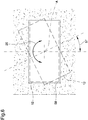
Figure 6 is a top view of the overall dimensions of the swivel head according to the invention in a particular embodiment; -
Figures 7 and 8 are two conceptual diagrams of the fluid-operated system of the swivel head according to the invention. - With particular reference to these illustrations,
reference numeral 1 globally indicates a swivel head for buckets. - The
swivel head 1 for grab buckets comprises afixed frame 2 associable with a machine in steady support. - Preferably, the
fixed frame 2 comprises acentral block 9 with a substantially cylindrical shape and comprising an upper fastening extreme 10 for fastening to the machinery and a lower extreme 11, substantially opposite the upper fastening extreme 10. - Advantageously, the upper fastening extreme 10 is associable with a holding cable of the support machinery to permit making it easier to position the
grab bucket 12. - The
swivel head 1 also comprises at least amovable frame 3 associated rotating with thefixed frame 2 around an axis of rotation A and associable with excavating means 4. - Conveniently, the
movable frame 3 is substantially interposed between thefixed frame 2 and the excavating means 4, which consist of agrab bucket 12 associated with themovable frame 3 and provided with a pair oftoothed clamshells 13 for excavating diaphragms. - Further embodiments cannot however be ruled out wherein the
movable frame 3 is associated with other excavating means 4 to be rotated, such as e.g., buckets provided with grabs, grapples or forks. - Preferably, the
grab bucket 12 comprises a support frame 21 of elongated shape, with a substantially rectangular cross section and substantially smaller in size than the cross section ofexcavation 58 made by the excavating means 4. - With particular reference to
figure 6 , the cross section of theexcavation 58 is substantially rectangular in shape, however, alternative embodiments cannot be ruled out wherein the excavating means 4 used for the excavation operations make anexcavation 58 with a cross section of different shape, e.g., oval. - This way, the excavating means 4 are easily introduced and removed from the
excavation 58 without the risk of thegrab bucket 12 remaining stuck in the ground. - Furthermore, the
swivel head 1 comprises at least afirst motor 5 comprising at least afirst element 6 associated integral in rotation with thefixed frame 2 and asecond element 7 kinematically connected to themovable frame 3, thefirst element 6 and thesecond element 7 being operable in rotation the one with respect to the other to rotate themovable frame 3 with respect to thefixed frame 2 around the axis of rotation A. - Preferably, the
first motor 5 is of the hydraulic type. - Furthermore, the
first element 6 and thesecond element 7 correspond to the crankshaft and to the motor body of thefirst motor 5, respectively. - Conveniently, the
first motor 5 is provided with two predefined end-of-stroke positions, spaced apart from one another by a first angular interval α and wherein thefirst element 6 is blockable with respect to thesecond element 7, thefirst element 6 and thesecond element 7 being movable the one with respect to the other in an alternate manner between the predefined end-of-stroke positions. The term "alternate", referred to the rotation of thefirst element 6 with respect to thesecond element 7, means that, after thefirst motor 5 has been started, thesecond element 7 rotates without interruption around the axis of rotation A until it reaches one of the end-of-stroke positions, i.e. after having covered an angle equal to the first angular interval α, at which point it stops until the subsequent start of thefirst motor 5. - More specifically, the start of the
first motor 5 involves the rotation around the axis of rotation A of thesecond element 7, which is free to rotate with respect to thefirst element 6 which, on the contrary, is locked in a fixed position because it is associated with thefixed frame 2. - Consequently, in response to a subsequent start of the
first motor 5, thesecond element 7 rotates around the axis of rotation A, in a direction contrary to the previous one, until it reaches the other of the end-of-stroke positions, i.e. the departure position. - More specifically, the fixed predefined departure position is reached after having covered backwards the first angular interval α covered during the first start of the
first motor 5. - Preferably, the first angular interval α is equal to 180°.
- Advantageously, the
swivel head 1 comprises asupport structure 14 of thesecond element 7 substantially centered with respect to the axis of rotation A. - More specifically, the
support structure 14 is provided with a perforatedupper base 15, through which passes thefirst element 6 to connect integral with the lower extreme 11 of thefixed frame 2, and with alower base 16 substantially opposite the perforatedupper base 15. - The
second element 7, on the other hand, is associated integral in rotation with thesupport structure 14. - The
swivel head 1 also comprises adjustment means 8 for adjusting the angular position of themovable frame 3 with respect to the fixedframe 2. - According to the invention, the adjustment means 8 comprise at least a
second motor 17 comprising at least afirst body 18 associated integral in rotation with thesecond element 7 and at least asecond body 19 associated integral in rotation with themovable frame 3. Thefirst body 18 and thesecond body 19 are operable in rotation the one with respect to the other to rotate themovable frame 3 with respect to thefixed frame 2 around the axis of rotation A and thesecond element 7 is integral in rotation to themovable frame 3 due to the reciprocal blockage of thefirst body 18 and of thesecond body 19. - The first and the
second body movable frame 3 with respect to thefixed frame 2, and an idle configuration wherein they are locked together and wherein the start of thefirst motor 5 involves the rotation of themovable frame 3. - Similarly to the
first motor 5, thefirst body 18 and thesecond body 19 correspond, respectively, to the crankshaft and motor body of thesecond motor 17. - Preferably the
second motor 17 is of the hydraulic type. - More specifically, the
first body 18 is associated integral in rotation with thelower base 16 of thesupport structure 14 and is placed underneath thefirst motor 5 at thesecond element 7, while thesecond body 19 is associated integral in rotation with themovable frame 3. - In other words, the
first element 6 rotates by 180° along the same arc of circumference alternately along a first direction of rotation and along a second direction of rotation opposite to the first. - Advantageously, the
second motor 17 is also provided with two predefined end-of-stroke positions, and thefirst body 18 and thesecond body 19 are movable one with respect to the other along a second angular interval and are blockable one with respect to the other in a plurality of positions during the displacement along the second angular interval itself. - In particular, the
first body 18 and thesecond body 19 are movable one with respect to the other in a "continuous" manner, where by such term referring to the rotation of thefirst body 18 with respect to thesecond body 19 is meant that the position of thefirst body 18 with respect to the position of thesecond body 19 can be arbitrarily fixed between the two end-of-stroke positions. The relative movement of thefirst body 18 with respect to thesecond body 19 is preferably performed in a manual manner by an operator. - In other words, after starting the
second motor 17, thesecond body 19 rotates around the axis of rotation A and can be locked in any angular position. Preferably, the second angular range is equal to ±90°. - More specifically, the start of the
second motor 17 involves the rotation around the axis of rotation A of thesecond body 19, which is free to rotate with respect to thefirst body 18 which, on the contrary, is locked in a fixed position because it is associated with thesupport structure 14. - Advantageously, the
second body 19 can reverse its direction of rotation in any angular position, without having to reach any of the predefined end-of-stroke positions. - Moreover, according to the idea behind the present invention, the
second motor 17 is positioned below thefirst motor 5. - More in detail, the
first element 6, thesecond element 7, thefirst body 18 and thesecond body 19 are arranged coaxially to one another. - With particular reference to these illustrations, the
first element 6, thesecond element 7, thefirst body 18 and thesecond body 19 have substantially circular cross sections and are centered along the axis of rotation A. - Alternative embodiments cannot however be ruled out wherein the
first element 6, thesecond element 7, thefirst body 18 and/or thesecond body 19 are made in different shapes, e.g., prismatic with square section, or wherein thefirst motor 5 and thesecond motor 17 are rotating around two axes of rotation parallel to each other. - This way, to a rotation of the
second element 7 around the axis of rotation A by an angle equal to the first angular interval α corresponds a rotation substantially identical of thesecond motor 17 around the axis of rotation A. - Advantageously, the
first body 18 is associated integral in rotation with thesupport structure 14 which in turn is integral in rotation to thesecond element 7. Thesecond body 19, on the other hand, is associated in rotation with themovable frame 3. - Suitably, the
swivel head 1 comprises at least a fluid-operatedsystem 22 for supplying a work fluid to at least one of thefirst motor 5 and thesecond motor 17. - Advantageously, the fluid-operated
system 22 is connectable in a fluid-operated manner to at least an external main supply source, e.g. mounted on the support machinery, and comprises a plurality ofconnection channels 23 adapted to connect in a fluid-operated manner the main supply source to thefirst motor 5 and thesecond motor 17. - However, alternative embodiments cannot be ruled out wherein there are, for example, two fluid-operated systems, one of which is dedicated to supplying the
first motor 5 and the other to supplying thesecond motor 17. - According to the idea behind the present invention, the fluid-operated
system 22 comprises at least a first fluid-operatedsystem 24 for supplying the work fluid to at least one of thefirst motor 5 and thesecond motor 17 and at least a second fluid-operatedsystem 25 for supplying the work fluid to the excavating means 4, where the first fluid-operatedsystem 24 is connected to the second fluid-operatedsystem 25. - In particular, the second fluid-operated
system 25 is connected in a fluid-operated manner to the main supply source to supply thetoothed clamshells 13 of thegrab bucket 12, and the first fluid-operatedsystem 24 is connected in a fluid-operated manner to the second fluid-operatedsystem 25 between the main supply source and thetoothed clamshells 13. - This way, a part of the work fluid flowing along the second fluid-operated
system 25 is diverted into the first fluid-operatedsystem 24. - Advantageously, the first fluid-operated
system 24 comprises at least anaccumulator 26 which is connectable in a fluid-operated manner to at least one of thefirst motor 5 and thesecond motor 17. - Preferably, the
accumulator 26 is associated with themovable frame 3, but alternative embodiments cannot however be ruled out wherein theaccumulator 26 is arranged in another position, e.g., wherein it is associated with the fixedframe 2. - Furthermore, the first fluid-operated
system 24 comprises valve means 27 for controlling the distribution of the work fluid towards at least one of thefirst motor 5, thesecond motor 17 and theaccumulator 26. - Preferably, the valve means 27 are associated with the
movable frame 3 and comprise a plurality of solenoid valves that can be activated to control the exchange of the work fluid arriving from the second fluid-operatedsystem 25 between thefirst motor 5, thesecond motor 17 and theaccumulator 26, respectively. - More in detail, the first fluid-operated
system 24 comprises aconnection link 29 between the second fluid-operatedsystem 25 and the valve means 27, afirst connection 30 between thefirst motor 5 and the valve means 27, asecond connection 31 between thesecond motor 17 and the valve means 27 and a third connection 56 between theaccumulator 26 and the valve means 27 to substantially form a network of fluid-operated connections for the circulation of the work fluid inside the first fluid-operatedsystem 24 as shown in the conceptual diagram infigure 6 . - Suitably, the valve means 27 are electrically controlled and the
head 1 comprises power supply means of the valve means 27. - The power supply means comprise at least a
supply battery 33 for supplying at least the valve means 27, at least a water-tight container 32 of thebattery 33 and electrical connection means 34 of thebattery 33 to the valve means 27. Preferably, thecontainer 32 is substantially cylindrical in shape and comprises agripping element 35 and amouth 36 arranged substantially opposite each other at the extremes of thecontainer 32. - The
swivel head 1 also comprises at least a fixedportion 37 associated with themovable frame 3 and removable fastening means 38 of thecontainer 32 to the fixedportion 37. - Advantageously, the fastening means 38 comprise first fastening means 39 associated with the
container 32 and second fastening means 40 associated with the fixedportion 37, where the first fastening means 39 and the second fastening means are adapted to operate in conjunction to fasten thecontainer 32 to the fixedportion 37 respectively. - The first fastening means 39 and the second fastening means 40 are, e.g., of the type of a threaded wall or of the interlocking type.
- The electrical connection means 34 comprise first connection means 41, 47 connected to the
battery 33 and second connection means 40, 43 connected to the valve means 27, where the first connection means 41, 47 are electrically separable from the second connection means 40, 43. - Advantageously, the first connection means 41, 47 are associated with the
container 32 and the second connection means 40, 43 are associated with the fixedportion 37, the fastening of thecontainer 32 to the fixedportion 37 electrically connecting the first connection means 41, 47 to the second connection means. - Preferably, the
container 32 is electrically conductive and the first connection means 41, 47 comprise at least a firstelectric conductor 41 positioned between thecontainer 32 and an electric pole of thebattery 33 and at least a secondelectric conductor 47 supported by thecontainer 32 and electrically connected to the other electric pole of thebattery 33. - More specifically, the first
electric conductor 41 extends towards the outside of thebattery 33 so as to rest on the internal conductive wall of thecontainer 32 when thebattery 33 is inserted inside thecontainer 32, as shown infigure 5 . Thecontainer 32 appropriately comprises a layer of conductive material which substantially covers the entire inner wall thereof. - Conveniently, the first connection means 41, 47 comprise a plurality of
first conductors 41 so as to ensure electrical contact between thebattery 33 and thecontainer 32 even in the event of thebattery 33 undergoing changes in position due to knocks or vibrations during excavation operations. - Advantageously, the
swivel head 1 comprises aplate 45 supporting the secondelectric conductor 47 and in turn supported by thecontainer 32. - More particularly, the
plate 45 is inserted through themouth 36 and engages with the first fastening means 39. - Suitably, the
plate 45 is made of insulating material. - In turn, the fixed
portion 37 comprises at least an electrically conductive supportingelement 44 and the second connection means 40, 43 comprise a thirdelectric conductor 40 associated with the supportingelement 44 and electrically connected to a pole of the valve means 27, and a fourthelectric conductor 43 electrically connected to the other pole of the valve means 27. - The third
electric conductor 40 and the fourthelectric conductor 43 are adapted to operate in conjunction with thecontainer 32 and the secondelectric conductor 47 as a result of the fastening of thecontainer 32 to the fixedportion 37, thus realizing the electric connection between thebattery 33 and the valve means 27. Preferably, the supportingelement 44 is coated with a layer of conductive material adapted to rest against the inner wall of thecontainer 32 as a result of the fastening of the latter to the fixedportion 37. - Conveniently, the
swivel head 1 comprises awireless communication unit 48 electrically associated with the valve means 27 and configured to receive at least an actuation signal of the valve means themselves. - More in detail, the
wireless communication unit 48 comprises a receiver antenna associated with themovable frame 3 and configured to receive a plurality of actuation signals to activate the solenoid valves sent by at least a remote wireless transmitter configured to remotely operate theswivel head 1. Furthermore, thewireless communication unit 48 comprises a signal processing unit associated with the receiver antenna and configured to process the signals received from the receiver antenna. - However, alternative embodiments cannot be ruled out wherein there is, e.g., a wired signal transmission network for the transmission of signals directly from the machinery to the signal processing unit without the use of a wireless transmitter.
- Advantageously, the
swivel head 1 comprises a chargingsystem 50 for recharging thebattery 33 comprising at least abypass branch 51 which is connected in a fluid-operated manner to the fluid-operatedsystem 22 and along which is arranged at least arotor element 52 operable in rotation due to the passage of the work fluid. - Preferably, the
bypass branch 51 is connected in a fluid-operated manner in parallel to the third connection 56, as shown infigure 6 . - The charging
system 50 also comprises at least an inductionelectric generator 53 which is kinematically connected to therotor element 52 and configured to convert the kinematic energy of therotor element 52 into electric energy, at least avoltage regulator 54 connected at output to the inductionelectric generator 53 and connected at input to at least one of thebattery 33 to be charged and user means comprising the valve means 27. - The operation of the invention is as follows.
- The
swivel head 1 can be activated via the remote wireless transmitter which sends an activation signal to thewireless communication unit 48. - The
wireless communication unit 48 processes the signal and drives the valve means 27 for the management of the work fluid inside the first fluid-operatedsystem 24. - Initially, by controlling the solenoid valves that open the
connection link 29 and the third connection 56, the first fluid-operatedsystem 24 fills theaccumulator 26 at least partly. - This way, at least part of the work fluid flowing inside the second fluid-operated
system 25 flows through theconnection link 29, and through the third connection 56, filling theaccumulator 26 at least partly. - Subsequently, the solenoid valves close the
connection link 29 and open thesecond connection 31. - This way, the work fluid passes from the
accumulator 26 to thesecond motor 17 to place thegrab bucket 12 in the desired excavation position. - More specifically, when the
second motor 17 is powered, thesecond body 19 rotates around the axis of rotation A. - Initially, the
first motor 5 is in one of the end-of-stroke positions and, therefore, thefirst element 6 and thesecond element 7 are locked together. - It follows, therefore, that the operation of the
second motor 17 causes the rotation of thesecond body 19 around the axis of rotation A, which drags themovable frame 3 in rotation. Themovable frame 3 is then rotated by acorrection angle 57 so as to position thegrab bucket 12 substantially aligned with theexcavation 58 to be made or previously started, as shown in thefigure 6 . - In other words, in this configuration, the
first element 6, thesecond element 7, thesupport structure 14 and thefirst body 18 are fixed integral with the fixedframe 2, while thesecond body 19 is free to rotate. - In other words, the
second motor 17 performs a calibration operation of the initial excavation position of thegrab bucket 12 so that the subsequent rotations made by thefirst motor 5 are made with reference to that initial position. - Once this position has been reached, the solenoid valves close the
second connection 31 so as to lock the position of thefirst body 18 with respect to thesecond body 19. - The machinery can then lower the
grab bucket 12 close to theexcavation 58 until thetoothed clamshells 13 reach the desired depth. - The second fluid-operated
system 25 supplies thetoothed clamshells 13 which, by opening and closing, sink into the ground to perform the operation of removal of the material which is necessary to carry out theexcavation 58. During the excavation operation, part of the work fluid which flows through the second fluid-operatedsystem 25 is conveyed into the first fluid-operatedsystem 24 to charge the electric accumulator 55. - The machinery then raises the
grab bucket 12 to move it away from theexcavation 58 in order to perform the unloading operation of the removed material. - Once the
grab bucket 12 has come out of the excavation, the solenoid valves are commanded to open thefirst connection 30 and operate thefirst motor 5, thus causing the rotation of thesecond element 7 around the axis of rotation A from one end-of-stroke position to another. - As described above, during this operation, the
first body 18 and thesecond body 19 are locked in a fixed position, the one with respect to the other, so that the start of thefirst motor 5 causes thesecond motor 17 to rotate and consequently themovable frame 3 to rotate around the axis A. - This way, the
second element 7 causes themovable frame 3 to rotate, and therefore thegrab bucket 12, around the axis of rotation A by an angle equal to the first angular interval α. - After rotation, the machinery returns the grab bucket at the
excavation 58 and repeats the operation of removal of the material from the bottom of the excavation being performed. - More specifically, during each unloading operation, the solenoid valves start the
first motor 5 which automatically rotates thesecond element 7 around the axis of rotation A, moving it from one end-of-stroke position to another. Advantageously, during the closure of thetoothed clamshells 13 carried out by the second fluid-operatedsystem 25 the solenoid valves open theconnection link 29 to divert part of the work fluid inside theaccumulator 26. - This way, the first fluid-operated
system 24 is always supplied with the work fluid for the starting of thefirst motor 5 and of thesecond motor 17. Furthermore, in the embodiment shown in the illustrations, when the solenoid valves open the third connection 56 at least part of the work fluid is diverted inside the chargingsystem 50. - More specifically, at least a part of the work fluid flows inside the
bypass branch 51 and sets in rotation therotor element 52 connected to the inductionelectric generator 53. - The
regulator 54 converts the alternating current supplied by the inductionelectric generator 53 into direct current which is adapted to charge thebattery 33 and to electrically supply the valve means 27. - More specifically, in the event of the
battery 33 being fully charged, thevoltage regulator 54 supplies the user means such as the valve means 27 or other electricity user points. - This way, at every operation of the
first motor 5 and of thesecond motor 17 and/or at every work fluid accumulation operation inside theaccumulator 26, part of the energy is recovered by the chargingsystem 50 to charge thebattery 33 and/or to supply the valve means 27 or other electricity user points. - This way, the replacement frequency of the
battery 33 is significantly reduced, with the consequent reduction in the machinery down times, and the energy absorbed by the user means 55 by any electric accumulators mounted on the support machinery is significantly reduced. - Conveniently, the battery replacement operation is done by unscrewing the
container 32 from the fixedportion 37 and screwing up in its place anothercontainer 32 containing another chargedbattery 33. - It has in practice been ascertained how the described invention fulfills the intended objects.
- In particular, the fact is underlined that the use of two motors to rotate the grab bucket makes it possible to specialize the first motor in the rotation necessary to carry out a symmetrical and regular excavation, and to specialize the second motor in the rotation necessary to align the bucket with the excavation or to correct any positioning errors found during excavation operations.
- This way, each motor is designed to best perform only one type of rotation and the use of an electronic position control system is not necessary.
- Furthermore, the arrangement of the first motor and of the second motor in series and integral in rotation the one with respect to the other makes it possible to perform the rotation operations carried out by the first motor and at the same time to maintain the calibration of the initial excavation position carried out at the start by the second motor.
- In addition, the use of a first fluid-operated system connected to the second fluid-operated system allows the work fluid used to operate the toothed clamshells also to operate the motors.
- More specifically, the presence of the accumulator allows the first fluid-operated system to store and always have at its disposal the work fluid needed to operate the motors.
- The use of a battery to power the valve means and the presence of a wireless communication unit mounted on the movable frame of the swivel head makes it possible to significantly reduce the electrical connections which would otherwise have to pass from the fixed frame to the movable frame with a consequent increase in the risk of failures due to excavation operations of the grab bucket.
- Furthermore, the presence of a removable container containing the battery and the corresponding fixed portion configured to achieve both the fastening of the battery to the movable frame and the connection with the valve means makes it possible to quickly and conveniently replace a container containing a discharged battery with another container containing a previously charged battery, thus avoiding long down times of the grab bucket to charge the battery and/or replace it.
- Finally, the fluid-operated charging system considerably extends the duration of the battery's electrical charge and significantly reduces the frequency of battery replacement.
Claims (15)
- Swivel head (1) for buckets, comprising:- at least a fixed frame (2) associable with a machine in steady support;- at least a movable frame (3) associated rotating with said fixed frame (2) around an axis of rotation A and associable with excavating means (4);characterized by the fact that it comprises:- at least a first motor (5) comprising at least a first element (6) associated integral in rotation with said fixed frame (2) and a second element (7) kinematically connected to said movable frame (3), said first element (6) and said second element (7) being operable in rotation the one with respect to the other to rotate said movable frame (3) with respect to said fixed frame (2) around said axis of rotation A;- adjustment means (8) for adjusting the angular position of said movable frame (3) with respect to said fixed frame (2), provided with at least a second motor (17) comprising at least a first body (18) associated integral in rotation with said second element (7) and at least a second body (19) associated integral in rotation with said movable frame (3), said first body (18) and said second body (19) being operable in rotation the one with respect to the other to rotate said movable frame (3) with respect to said fixed frame (2) around said axis of rotation A, said second element (7) being integral in rotation to said movable frame (3) due to the reciprocal blockage of said first body (18) and of said second body (19).
- Swivel head (1) according to claim 1, characterized by the fact that said first motor (5) is provided with two predefined end-of-stroke positions, spaced apart from one another by a first angular interval and wherein said first element (6) is blockable with respect to said second element (7), said first element (6) and said second element (7) being movable the one with respect to the other in an alternate manner between said predefined end-of-stroke positions.
- Swivel head (1) according to one or more of the preceding claims, characterized by the fact that said second motor (17) is provided with two predefined end-of-stroke positions spaced apart from one another by a second angular interval, said first body (18) and said second body (19) being blockable the one with respect to the other in a plurality of positions in the displacement along said second angular interval.
- Swivel head (1) according to one or more of the preceding claims, characterized by the fact that said first element (6), said second element (7), said first body (18) and said second body (19) are arranged coaxially to one another.
- Swivel head (1) according to one or more of the preceding claims, characterized by the fact that it comprises at least a fluid-operated system (22) for supplying a work fluid to at least one of said first motor (5) and said second motor (17).
- Swivel head (1) according to one or more of the preceding claims, characterized by the fact that said fluid-operated system (22) comprises at least a first fluid-operated system (24) for supplying the work fluid to at least one of said first motor (5) and said second motor (17) and at least a second fluid-operated system (25) for supplying the work fluid to said excavating means (4), said first fluid-operated system (24) being connected to said second fluid-operated system (25).
- Swivel head (1) according to one or more of the preceding claims, characterized by the fact that said first fluid-operated system (24) comprises at least an accumulator (26) which is connectable in a fluid-operated manner to at least one of said first motor (5) and said second motor (17).
- Swivel head (1) according to one or more of the preceding claims, characterized by the fact that said first fluid-operated system (24) comprises valve means (27) for controlling the distribution of the work fluid towards at least one of said first motor (5), said second motor (17) and said accumulator (26).
- Swivel head (1) according to one or more of the preceding claims, characterized by the fact that said valve means are electrically controlled and by the fact of comprising at least a supply battery (33) for supplying at least said valve means (27) and at least a water-tight container (32) of said battery (33), electrical connection means being provided for the connection of said battery (33) to said valve means (27).
- Swivel head (1) according to one or more of the preceding claims, characterized by the fact that it comprises at least a fixed portion (37) associated with said movable frame (3) and removable fastening means (38) of said container (32) to said fixed portion (37).
- Swivel head (1) according to one or more of the preceding claims, characterized by the fact that said electrical connection means (34) comprise first connection means (41, 47) connected to said battery (33) and second connection means (40, 43) connected to said valve means (27), where said first means are electrically separable from said second connection means.
- Swivel head (1) according to one or more of the preceding claims, characterized by the fact that said first connection means (41, 42) are associated with said container (32) and said second connection means (40, 43) are associated with said fixed portion (37), the fastening of said container (32) to said fixed portion (37) electrically connecting said first connection means (41, 47) to said second connection means.
- Swivel head (1) according to one or more of the preceding claims, characterized by the fact that said container (32) is electrically conductive and said first connection means (41, 47) comprise at least a first electric conductor (41) positioned between said container (32) and an electric pole of said battery (33) and at least a second electric conductor (47) supported by said container (32) and electrically connected to the other electric pole of said battery (33) and characterized by the fact that said fixed portion (37) comprises at least a supporting element (44) and that said second connection means (40, 43) comprise a third electric conductor (40) associated with said supporting element (44), which is electrically connected to a pole of said valve means (27) and is adapted to operate in conjunction with said container (32) as a result of the fastening to said fixed portion (37), and a fourth electric conductor (43) electrically connected to the other pole of said valve means (27) and adapted to operate in conjunction with said second electric conductor (47) as a result of the fastening of said container (32) to said fixed portion (37).
- Swivel head (1) according to one or more of the preceding claims, characterized by the fact that it comprises a wireless communication unit (48) electrically associated with said valve means (27) and configured to receive at least an actuation signal of said valve means (27) for varying the distribution of said fluid.
- Swivel head (1) according to one or more of the preceding claims, characterized by the fact that it comprises a charging system (50) of said battery (33) comprising:- at least a bypass branch (51) which is connected in a fluid-operated manner to said fluid-operated system (22);- at least a rotor element (52) arranged along said bypass branch (51) and operable in rotation due to said fluid;- at least an induction electric generator (53) which is kinematically connected to said rotor element (52) and configured to convert the kinematic energy of said rotor element (52) into electric energy;- at least a voltage regulator (54) connected at output to said induction electric generator (53) and at input to at least one of said battery (33) and user means comprising at least said valve means (27), said voltage regulator (54) charging said battery (33) and/or electrically supplying said user means.
Applications Claiming Priority (1)
| Application Number | Priority Date | Filing Date | Title |
|---|---|---|---|
| IT102017000091689A IT201700091689A1 (en) | 2017-08-08 | 2017-08-08 | ADJUSTABLE HEAD FOR BUCKETS |
Publications (2)
| Publication Number | Publication Date |
|---|---|
| EP3441531A1 EP3441531A1 (en) | 2019-02-13 |
| EP3441531B1 true EP3441531B1 (en) | 2020-10-07 |
Family
ID=60991126
Family Applications (1)
| Application Number | Title | Priority Date | Filing Date |
|---|---|---|---|
| EP18187352.2A Active EP3441531B1 (en) | 2017-08-08 | 2018-08-03 | Swivel head for buckets |
Country Status (2)
| Country | Link |
|---|---|
| EP (1) | EP3441531B1 (en) |
| IT (1) | IT201700091689A1 (en) |
Families Citing this family (1)
| Publication number | Priority date | Publication date | Assignee | Title |
|---|---|---|---|---|
| IT201800020152A1 (en) * | 2018-12-18 | 2020-06-18 | Negrini Srl | BUCKET FOR WORKING MACHINES |
Family Cites Families (3)
| Publication number | Priority date | Publication date | Assignee | Title |
|---|---|---|---|---|
| US4958981A (en) * | 1988-12-20 | 1990-09-25 | Masatoshi Uchihashi | Attachment connector assembly for hydraulic shovel type excavator |
| ATE442339T1 (en) * | 2006-04-03 | 2009-09-15 | Epsilon Kran Gmbh | CRANE ARM WITH A FASTENING DEVICE FOR WORK EQUIPMENT |
| US10100487B2 (en) * | 2013-07-10 | 2018-10-16 | Tigercat Industries Inc. | Hydraulic assembly and logging equipment using same |
-
2017
- 2017-08-08 IT IT102017000091689A patent/IT201700091689A1/en unknown
-
2018
- 2018-08-03 EP EP18187352.2A patent/EP3441531B1/en active Active
Non-Patent Citations (1)
| Title |
|---|
| None * |
Also Published As
| Publication number | Publication date |
|---|---|
| EP3441531A1 (en) | 2019-02-13 |
| IT201700091689A1 (en) | 2019-02-08 |
Similar Documents
| Publication | Publication Date | Title |
|---|---|---|
| US10954652B2 (en) | Assembly and method for installing a subsea cable | |
| RU2522985C2 (en) | Method for mine vehicle use, mine device, drilling rig for mine rocks and mine vehicle | |
| EP2962890A1 (en) | Energy storage robot | |
| EP3441531A1 (en) | Swivel head for buckets | |
| CN103192396A (en) | Concrete pumping equipment and motion control system and method of tail end hose thereof | |
| KR101704829B1 (en) | Electric excavator system | |
| CN110206088B (en) | A crawler-type vertical dredging system for shafts | |
| CN104553831A (en) | Mining vehicle and method for energy supply thereof | |
| CN211690727U (en) | Dredging robot with correction device | |
| CN103867409A (en) | Gravity energy storage system utilizing ocean depth drop | |
| CN109424318A (en) | Drill jumbo and its control method with long-range remote control function | |
| KR101367099B1 (en) | Excavating screw for auger crane and backhoe having camera for locating buried objects | |
| CN214363726U (en) | a buried plow | |
| KR20100022835A (en) | A rotatable crane hookblock powered by a lifting cable and its control method | |
| KR101523502B1 (en) | Safety diagnosis equipment of underground cable | |
| RU2507431C2 (en) | Production method of excavation and laying works at routing of underwater pipelines, and device for its implementation | |
| KR20130049902A (en) | Electric excavator | |
| KR20120036461A (en) | Apparatus for laying corrugated pipe | |
| JP2018039675A (en) | Construction machinery | |
| KR20120114880A (en) | Electric excavator system | |
| JP5373204B2 (en) | Rock drilling equipment | |
| CN108843856A (en) | Push-bench and its control method | |
| CN210507587U (en) | A crawler shaft vertical dredging system | |
| CN208816842U (en) | Push-bench | |
| RU2772085C1 (en) | System of transmission of electrical energy to the traverse of the railway laying crane |
Legal Events
| Date | Code | Title | Description |
|---|---|---|---|
| PUAI | Public reference made under article 153(3) epc to a published international application that has entered the european phase |
Free format text: ORIGINAL CODE: 0009012 |
|
| STAA | Information on the status of an ep patent application or granted ep patent |
Free format text: STATUS: THE APPLICATION HAS BEEN PUBLISHED |
|
| AK | Designated contracting states |
Kind code of ref document: A1 Designated state(s): AL AT BE BG CH CY CZ DE DK EE ES FI FR GB GR HR HU IE IS IT LI LT LU LV MC MK MT NL NO PL PT RO RS SE SI SK SM TR |
|
| AX | Request for extension of the european patent |
Extension state: BA ME |
|
| STAA | Information on the status of an ep patent application or granted ep patent |
Free format text: STATUS: REQUEST FOR EXAMINATION WAS MADE |
|
| 17P | Request for examination filed |
Effective date: 20190730 |
|
| RBV | Designated contracting states (corrected) |
Designated state(s): AL AT BE BG CH CY CZ DE DK EE ES FI FR GB GR HR HU IE IS IT LI LT LU LV MC MK MT NL NO PL PT RO RS SE SI SK SM TR |
|
| GRAP | Despatch of communication of intention to grant a patent |
Free format text: ORIGINAL CODE: EPIDOSNIGR1 |
|
| STAA | Information on the status of an ep patent application or granted ep patent |
Free format text: STATUS: GRANT OF PATENT IS INTENDED |
|
| INTG | Intention to grant announced |
Effective date: 20200424 |
|
| GRAS | Grant fee paid |
Free format text: ORIGINAL CODE: EPIDOSNIGR3 |
|
| GRAA | (expected) grant |
Free format text: ORIGINAL CODE: 0009210 |
|
| STAA | Information on the status of an ep patent application or granted ep patent |
Free format text: STATUS: THE PATENT HAS BEEN GRANTED |
|
| AK | Designated contracting states |
Kind code of ref document: B1 Designated state(s): AL AT BE BG CH CY CZ DE DK EE ES FI FR GB GR HR HU IE IS IT LI LT LU LV MC MK MT NL NO PL PT RO RS SE SI SK SM TR |
|
| REG | Reference to a national code |
Ref country code: GB Ref legal event code: FG4D |
|
| REG | Reference to a national code |
Ref country code: CH Ref legal event code: EP Ref country code: AT Ref legal event code: REF Ref document number: 1321283 Country of ref document: AT Kind code of ref document: T Effective date: 20201015 |
|
| REG | Reference to a national code |
Ref country code: DE Ref legal event code: R096 Ref document number: 602018008442 Country of ref document: DE |
|
| REG | Reference to a national code |
Ref country code: IE Ref legal event code: FG4D |
|
| REG | Reference to a national code |
Ref country code: NL Ref legal event code: MP Effective date: 20201007 |
|
| REG | Reference to a national code |
Ref country code: AT Ref legal event code: MK05 Ref document number: 1321283 Country of ref document: AT Kind code of ref document: T Effective date: 20201007 |
|
| PG25 | Lapsed in a contracting state [announced via postgrant information from national office to epo] |
Ref country code: NO Free format text: LAPSE BECAUSE OF FAILURE TO SUBMIT A TRANSLATION OF THE DESCRIPTION OR TO PAY THE FEE WITHIN THE PRESCRIBED TIME-LIMIT Effective date: 20210107 Ref country code: GR Free format text: LAPSE BECAUSE OF FAILURE TO SUBMIT A TRANSLATION OF THE DESCRIPTION OR TO PAY THE FEE WITHIN THE PRESCRIBED TIME-LIMIT Effective date: 20210108 Ref country code: FI Free format text: LAPSE BECAUSE OF FAILURE TO SUBMIT A TRANSLATION OF THE DESCRIPTION OR TO PAY THE FEE WITHIN THE PRESCRIBED TIME-LIMIT Effective date: 20201007 Ref country code: RS Free format text: LAPSE BECAUSE OF FAILURE TO SUBMIT A TRANSLATION OF THE DESCRIPTION OR TO PAY THE FEE WITHIN THE PRESCRIBED TIME-LIMIT Effective date: 20201007 Ref country code: PT Free format text: LAPSE BECAUSE OF FAILURE TO SUBMIT A TRANSLATION OF THE DESCRIPTION OR TO PAY THE FEE WITHIN THE PRESCRIBED TIME-LIMIT Effective date: 20210208 |
|
| REG | Reference to a national code |
Ref country code: LT Ref legal event code: MG4D |
|
| PG25 | Lapsed in a contracting state [announced via postgrant information from national office to epo] |
Ref country code: SE Free format text: LAPSE BECAUSE OF FAILURE TO SUBMIT A TRANSLATION OF THE DESCRIPTION OR TO PAY THE FEE WITHIN THE PRESCRIBED TIME-LIMIT Effective date: 20201007 Ref country code: LV Free format text: LAPSE BECAUSE OF FAILURE TO SUBMIT A TRANSLATION OF THE DESCRIPTION OR TO PAY THE FEE WITHIN THE PRESCRIBED TIME-LIMIT Effective date: 20201007 Ref country code: PL Free format text: LAPSE BECAUSE OF FAILURE TO SUBMIT A TRANSLATION OF THE DESCRIPTION OR TO PAY THE FEE WITHIN THE PRESCRIBED TIME-LIMIT Effective date: 20201007 Ref country code: IS Free format text: LAPSE BECAUSE OF FAILURE TO SUBMIT A TRANSLATION OF THE DESCRIPTION OR TO PAY THE FEE WITHIN THE PRESCRIBED TIME-LIMIT Effective date: 20210207 Ref country code: BG Free format text: LAPSE BECAUSE OF FAILURE TO SUBMIT A TRANSLATION OF THE DESCRIPTION OR TO PAY THE FEE WITHIN THE PRESCRIBED TIME-LIMIT Effective date: 20210107 Ref country code: AT Free format text: LAPSE BECAUSE OF FAILURE TO SUBMIT A TRANSLATION OF THE DESCRIPTION OR TO PAY THE FEE WITHIN THE PRESCRIBED TIME-LIMIT Effective date: 20201007 Ref country code: ES Free format text: LAPSE BECAUSE OF FAILURE TO SUBMIT A TRANSLATION OF THE DESCRIPTION OR TO PAY THE FEE WITHIN THE PRESCRIBED TIME-LIMIT Effective date: 20201007 |
|
| PG25 | Lapsed in a contracting state [announced via postgrant information from national office to epo] |
Ref country code: NL Free format text: LAPSE BECAUSE OF FAILURE TO SUBMIT A TRANSLATION OF THE DESCRIPTION OR TO PAY THE FEE WITHIN THE PRESCRIBED TIME-LIMIT Effective date: 20201007 Ref country code: HR Free format text: LAPSE BECAUSE OF FAILURE TO SUBMIT A TRANSLATION OF THE DESCRIPTION OR TO PAY THE FEE WITHIN THE PRESCRIBED TIME-LIMIT Effective date: 20201007 |
|
| REG | Reference to a national code |
Ref country code: DE Ref legal event code: R097 Ref document number: 602018008442 Country of ref document: DE |
|
| PG25 | Lapsed in a contracting state [announced via postgrant information from national office to epo] |
Ref country code: EE Free format text: LAPSE BECAUSE OF FAILURE TO SUBMIT A TRANSLATION OF THE DESCRIPTION OR TO PAY THE FEE WITHIN THE PRESCRIBED TIME-LIMIT Effective date: 20201007 Ref country code: CZ Free format text: LAPSE BECAUSE OF FAILURE TO SUBMIT A TRANSLATION OF THE DESCRIPTION OR TO PAY THE FEE WITHIN THE PRESCRIBED TIME-LIMIT Effective date: 20201007 Ref country code: SM Free format text: LAPSE BECAUSE OF FAILURE TO SUBMIT A TRANSLATION OF THE DESCRIPTION OR TO PAY THE FEE WITHIN THE PRESCRIBED TIME-LIMIT Effective date: 20201007 Ref country code: SK Free format text: LAPSE BECAUSE OF FAILURE TO SUBMIT A TRANSLATION OF THE DESCRIPTION OR TO PAY THE FEE WITHIN THE PRESCRIBED TIME-LIMIT Effective date: 20201007 Ref country code: RO Free format text: LAPSE BECAUSE OF FAILURE TO SUBMIT A TRANSLATION OF THE DESCRIPTION OR TO PAY THE FEE WITHIN THE PRESCRIBED TIME-LIMIT Effective date: 20201007 Ref country code: LT Free format text: LAPSE BECAUSE OF FAILURE TO SUBMIT A TRANSLATION OF THE DESCRIPTION OR TO PAY THE FEE WITHIN THE PRESCRIBED TIME-LIMIT Effective date: 20201007 |
|
| PLBE | No opposition filed within time limit |
Free format text: ORIGINAL CODE: 0009261 |
|
| STAA | Information on the status of an ep patent application or granted ep patent |
Free format text: STATUS: NO OPPOSITION FILED WITHIN TIME LIMIT |
|
| PG25 | Lapsed in a contracting state [announced via postgrant information from national office to epo] |
Ref country code: DK Free format text: LAPSE BECAUSE OF FAILURE TO SUBMIT A TRANSLATION OF THE DESCRIPTION OR TO PAY THE FEE WITHIN THE PRESCRIBED TIME-LIMIT Effective date: 20201007 |
|
| 26N | No opposition filed |
Effective date: 20210708 |
|
| PG25 | Lapsed in a contracting state [announced via postgrant information from national office to epo] |
Ref country code: AL Free format text: LAPSE BECAUSE OF FAILURE TO SUBMIT A TRANSLATION OF THE DESCRIPTION OR TO PAY THE FEE WITHIN THE PRESCRIBED TIME-LIMIT Effective date: 20201007 |
|
| PG25 | Lapsed in a contracting state [announced via postgrant information from national office to epo] |
Ref country code: SI Free format text: LAPSE BECAUSE OF FAILURE TO SUBMIT A TRANSLATION OF THE DESCRIPTION OR TO PAY THE FEE WITHIN THE PRESCRIBED TIME-LIMIT Effective date: 20201007 |
|
| REG | Reference to a national code |
Ref country code: CH Ref legal event code: PL |
|
| PG25 | Lapsed in a contracting state [announced via postgrant information from national office to epo] |
Ref country code: MC Free format text: LAPSE BECAUSE OF FAILURE TO SUBMIT A TRANSLATION OF THE DESCRIPTION OR TO PAY THE FEE WITHIN THE PRESCRIBED TIME-LIMIT Effective date: 20201007 |
|
| REG | Reference to a national code |
Ref country code: BE Ref legal event code: MM Effective date: 20210831 |
|
| PG25 | Lapsed in a contracting state [announced via postgrant information from national office to epo] |
Ref country code: LI Free format text: LAPSE BECAUSE OF NON-PAYMENT OF DUE FEES Effective date: 20210831 Ref country code: CH Free format text: LAPSE BECAUSE OF NON-PAYMENT OF DUE FEES Effective date: 20210831 |
|
| PG25 | Lapsed in a contracting state [announced via postgrant information from national office to epo] |
Ref country code: IS Free format text: LAPSE BECAUSE OF FAILURE TO SUBMIT A TRANSLATION OF THE DESCRIPTION OR TO PAY THE FEE WITHIN THE PRESCRIBED TIME-LIMIT Effective date: 20210207 Ref country code: LU Free format text: LAPSE BECAUSE OF NON-PAYMENT OF DUE FEES Effective date: 20210803 |
|
| PG25 | Lapsed in a contracting state [announced via postgrant information from national office to epo] |
Ref country code: IE Free format text: LAPSE BECAUSE OF NON-PAYMENT OF DUE FEES Effective date: 20210803 Ref country code: FR Free format text: LAPSE BECAUSE OF NON-PAYMENT OF DUE FEES Effective date: 20210831 Ref country code: BE Free format text: LAPSE BECAUSE OF NON-PAYMENT OF DUE FEES Effective date: 20210831 |
|
| REG | Reference to a national code |
Ref country code: DE Ref legal event code: R082 Ref document number: 602018008442 Country of ref document: DE Representative=s name: WOERZ PATENTANWAELTE PARTNERSCHAFTSGESELLSCHAF, DE |
|
| GBPC | Gb: european patent ceased through non-payment of renewal fee |
Effective date: 20220803 |
|
| PG25 | Lapsed in a contracting state [announced via postgrant information from national office to epo] |
Ref country code: CY Free format text: LAPSE BECAUSE OF FAILURE TO SUBMIT A TRANSLATION OF THE DESCRIPTION OR TO PAY THE FEE WITHIN THE PRESCRIBED TIME-LIMIT Effective date: 20201007 |
|
| P01 | Opt-out of the competence of the unified patent court (upc) registered |
Effective date: 20230527 |
|
| PG25 | Lapsed in a contracting state [announced via postgrant information from national office to epo] |
Ref country code: HU Free format text: LAPSE BECAUSE OF FAILURE TO SUBMIT A TRANSLATION OF THE DESCRIPTION OR TO PAY THE FEE WITHIN THE PRESCRIBED TIME-LIMIT; INVALID AB INITIO Effective date: 20180803 |
|
| PG25 | Lapsed in a contracting state [announced via postgrant information from national office to epo] |
Ref country code: GB Free format text: LAPSE BECAUSE OF NON-PAYMENT OF DUE FEES Effective date: 20220803 |
|
| PG25 | Lapsed in a contracting state [announced via postgrant information from national office to epo] |
Ref country code: MK Free format text: LAPSE BECAUSE OF FAILURE TO SUBMIT A TRANSLATION OF THE DESCRIPTION OR TO PAY THE FEE WITHIN THE PRESCRIBED TIME-LIMIT Effective date: 20201007 |
|
| PG25 | Lapsed in a contracting state [announced via postgrant information from national office to epo] |
Ref country code: MT Free format text: LAPSE BECAUSE OF FAILURE TO SUBMIT A TRANSLATION OF THE DESCRIPTION OR TO PAY THE FEE WITHIN THE PRESCRIBED TIME-LIMIT Effective date: 20201007 |
|
| PGFP | Annual fee paid to national office [announced via postgrant information from national office to epo] |
Ref country code: DE Payment date: 20250827 Year of fee payment: 8 |
|
| PGFP | Annual fee paid to national office [announced via postgrant information from national office to epo] |
Ref country code: IT Payment date: 20250825 Year of fee payment: 8 |
|
| PG25 | Lapsed in a contracting state [announced via postgrant information from national office to epo] |
Ref country code: TR Free format text: LAPSE BECAUSE OF FAILURE TO SUBMIT A TRANSLATION OF THE DESCRIPTION OR TO PAY THE FEE WITHIN THE PRESCRIBED TIME-LIMIT Effective date: 20201007 |