EP3441343A1 - Yarn withdrawal device and yarn winding machine - Google Patents
Yarn withdrawal device and yarn winding machine Download PDFInfo
- Publication number
- EP3441343A1 EP3441343A1 EP18181647.1A EP18181647A EP3441343A1 EP 3441343 A1 EP3441343 A1 EP 3441343A1 EP 18181647 A EP18181647 A EP 18181647A EP 3441343 A1 EP3441343 A1 EP 3441343A1
- Authority
- EP
- European Patent Office
- Prior art keywords
- yarn
- slit
- package
- airflow
- withdrawal device
- Prior art date
- Legal status (The legal status is an assumption and is not a legal conclusion. Google has not performed a legal analysis and makes no representation as to the accuracy of the status listed.)
- Withdrawn
Links
- 238000004804 winding Methods 0.000 title claims description 107
- 125000006850 spacer group Chemical group 0.000 claims description 45
- 238000002347 injection Methods 0.000 claims description 9
- 239000007924 injection Substances 0.000 claims description 9
- 238000005304 joining Methods 0.000 description 26
- 238000009987 spinning Methods 0.000 description 10
- 238000000034 method Methods 0.000 description 6
- 230000001105 regulatory effect Effects 0.000 description 5
- 238000011144 upstream manufacturing Methods 0.000 description 5
- 230000007547 defect Effects 0.000 description 4
- 230000002093 peripheral effect Effects 0.000 description 3
- 230000001419 dependent effect Effects 0.000 description 2
- 238000001514 detection method Methods 0.000 description 2
- 239000000835 fiber Substances 0.000 description 2
- 239000012530 fluid Substances 0.000 description 2
- 244000126211 Hericium coralloides Species 0.000 description 1
- 238000005520 cutting process Methods 0.000 description 1
- 238000004519 manufacturing process Methods 0.000 description 1
- 238000012544 monitoring process Methods 0.000 description 1
- 238000007383 open-end spinning Methods 0.000 description 1
- 238000005192 partition Methods 0.000 description 1
- 239000000126 substance Substances 0.000 description 1
Images



Classifications
-
- B—PERFORMING OPERATIONS; TRANSPORTING
- B65—CONVEYING; PACKING; STORING; HANDLING THIN OR FILAMENTARY MATERIAL
- B65H—HANDLING THIN OR FILAMENTARY MATERIAL, e.g. SHEETS, WEBS, CABLES
- B65H67/00—Replacing or removing cores, receptacles, or completed packages at paying-out, winding, or depositing stations
- B65H67/08—Automatic end-finding and material-interconnecting arrangements
- B65H67/081—Automatic end-finding and material-interconnecting arrangements acting after interruption of the winding process, e.g. yarn breakage, yarn cut or package replacement
- B65H67/085—Automatic end-finding and material-interconnecting arrangements acting after interruption of the winding process, e.g. yarn breakage, yarn cut or package replacement end-finding at the take-up package, e.g. by suction and reverse package rotation
-
- B—PERFORMING OPERATIONS; TRANSPORTING
- B65—CONVEYING; PACKING; STORING; HANDLING THIN OR FILAMENTARY MATERIAL
- B65H—HANDLING THIN OR FILAMENTARY MATERIAL, e.g. SHEETS, WEBS, CABLES
- B65H67/00—Replacing or removing cores, receptacles, or completed packages at paying-out, winding, or depositing stations
- B65H67/08—Automatic end-finding and material-interconnecting arrangements
-
- B—PERFORMING OPERATIONS; TRANSPORTING
- B65—CONVEYING; PACKING; STORING; HANDLING THIN OR FILAMENTARY MATERIAL
- B65H—HANDLING THIN OR FILAMENTARY MATERIAL, e.g. SHEETS, WEBS, CABLES
- B65H2701/00—Handled material; Storage means
- B65H2701/30—Handled filamentary material
- B65H2701/31—Textiles threads or artificial strands of filaments
Definitions
- the present invention mainly relates to a yarn withdrawal device adapted to withdraw a yarn from a package.
- a yarn withdrawal device arranged in proximity to a package and adapted to withdraw a yarn of the package to perform, for example, yarn joining operation is conventionally known.
- This type of yarn withdrawal device is disclosed in Japanese Patent Application Laid-open No. 2014-125348 (patent document 1), Japanese Utility Model Application Laid-open No. H5-5769 (patent document 2), and German Patent Application Publication No. 2426724 (patent document 3).
- Patent document 1 discloses a yarn withdrawal device formed with one slit for injecting compressed air. Airflow generated by the compressed air injected from the slit flows along an outer wall surface of the yarn withdrawal device. Since the outer wall surface is arranged in proximity to the package, a yarn is withdrawn from the package by the airflow.
- Patent documents 2 and 3 disclose yarn end withdrawal devices having a structure in which two nozzle tubes are arranged in an axial direction of the package. A plurality of nozzle holes are formed in each of the two nozzle tubes. A yarn entangled with the surface of the package can be detached (separated, removed, lifted) from the package by injecting the air from such nozzle holes.
- a yarn withdrawal device having the following structure. That is, the yarn withdrawal device includes a first injecting section and a second injecting section.
- the first injecting section is formed with a first slit and adapted to generate a first airflow by air being injected from the first slit.
- the second injecting section is formed with a second slit along a longitudinal direction of the first slit and adapted to generate second airflow by air being injected from the second slit, the second airflow being an airflow flowing in a direction different from a direction of the first airflow.
- the airflows along different flow directions are generated from the two slits, whereby the airflow can be easily acted on the package in a wide range.
- the probability of succeeding in withdrawal of a yarn from a package can be increased.
- the yarn withdrawal device includes a main body part, a first injecting section, and a second injecting section.
- the first injecting section includes a first spacer portion and a first cover portion, a first slit being formed by the first spacer portion being arranged between the first cover portion and the main body part, the first injecting section being adapted to generate a first airflow by air being injected from the first slit.
- the second injecting section includes a second spacer portion and a second cover portion, a second slit being formed by the second spacer portion being arranged between the second cover portion and the first cover portion, the second injecting section being adapted to generate a second airflow by air being injected from the second slit.
- the airflow is generated from each of the two slits formed at different positions, whereby the airflows along different flow directions can easily act on the package. As a result, the probability of succeeding in withdrawal of a yarn from a package can be increased.
- a thickness of at least one of the first spacer portion and the second spacer portion is preferably greater than or equal to 0.01mm and less than or equal to 5mm.
- the success rate of the withdrawal of the yarn from the package can be sufficiently increased while reducing the amount of air supplied to the yarn withdrawal device.
- the yarn withdrawal device preferably includes at least one of a first inclined surface and a second inclined surface, the first inclined surface being inclined so as to be continuous to a basal end of a flow of the first airflow and continuous to the first slit, and the second inclined surface being inclined so as to be continuous to a basal end of a flow of the second airflow and continuous to the second slit.
- the air around the first slit and/or the second slit can be drawn into the first airflow and/or the second airflow, whereby the yarn from the package can be withdrawn while reducing the amount of air supplied to the yarn withdrawal device.
- a surface adapted to guide air before being injected from the second slit preferably has an injection direction correcting surface inclined such that a height of the second slit increases towards an end of the second slit from which the second airflow is injected.
- the second airflow flows away from the outer surface of the yarn withdrawal device, the second airflow can easily hit the package.
- the yarn withdrawal device preferably includes a guiding section arranged downstream in a flow direction of the first airflow and adapted to guide the yarn withdrawn from the package towards center in a longitudinal direction of the first slit.
- the position of the yarn withdrawn from the package by the yarn withdrawal device is thereby defined, and thus a next process can be easily carried out.
- the yarn withdrawal device preferably has the following structure. That is, the yarn withdrawal device includes a first outer surface and a second outer surface.
- the first outer surface is provided with the first slit and the second slit.
- the second outer surface is arranged downstream in the flow direction of the first airflow with respect to the first outer surface.
- the guiding section is provided on the second outer surface.
- the surface (first outer surface) for withdrawing the yarn from the package, and the surface (second outer surface) for guiding the withdrawn yarn can be separated, whereby the size of the yarn withdrawal device can be reduced.
- the yarn withdrawal device preferably has the following structure. That is, a first guiding surface and a second guiding surface are formed on the guiding section and arranged to protrude from the second outer surface and to face one another. An interval between the first guiding surface and the second guiding surface increases towards the first outer surface.
- the yarn withdrawn from the package is easily guided by the guiding section. Furthermore, as the yarn is guided to a narrow range by the guiding section, the next process can be easily carried out.
- the yarn withdrawal device preferably includes a curved surface smoothly connecting the first outer surface and the second outer surface and being curved to project outward.
- the second airflow easily flows in the direction different from the flow of the first airflow.
- a yarn winding machine having the following configuration. That is, the yarn winding machine includes the yarn withdrawal device and a winding section.
- the winding section is adapted to rotate a winding tube in a winding direction to form the package by winding the yarn.
- a longitudinal direction of the first slit is along an axial direction of the package.
- the yarn winding machine preferably has the following structure. That is, a flow direction of the first airflow is set to guide the yarn withdrawn from the package to a first target position, and a flow direction of the second airflow is set towards the package.
- the yarn can be withdrawn from the package and the withdrawn yarn can be guided to the first target position.
- the yarn winding machine preferably has the following structure. That is, the winding section is configured to rotate the package also in a reverse rotational direction, which is a direction opposite to the winding direction.
- the second slit is formed downstream of the first slit in the reverse rotational direction of the package.
- the yarn is detached (separated, removed, lifted) from the package or the detaching of the yarn is assisted by the second airflow, and the detached yarn can be fed downstream by the first airflow.
- the yarn winding machine preferably has the following structure. That is, the yarn winding machine includes a first catching member adapted to catch the yarn withdrawn from the package by the yarn withdrawal device.
- the first target position is a catching position of the first catching member.
- the success rate of the catching of the yarn by the first catching member thus can be increased.
- the yarn winding machine preferably has the following structure. That is, the first catching member is adapted to catch the yarn by sucking the yarn and to guide the caught yarn to a second target position. A suction force of the first catching member is set such that a suction force when catching the yarn is greater than a suction force when guiding the yarn to the second target position.
- the yarn winding machine preferably includes a second catching member adapted to receive the caught yarn from the first catching member and to guide the yarn to a third target position,
- the yarn can be guided to the target position while reducing the size and/or movable range of each catching member.
- the yarn winding machine preferably has the following structure. That is, the yarn winding machine includes a plurality of winding units and a service vehicle.
- the winding units each includes at least the winding section.
- the service vehicle is adapted to be movable with respect to the plurality of the winding units.
- the service vehicle includes the yarn withdrawal device.
- the cost of the yarn winding machine can be reduced by arranging one yarn withdrawal device with respect to the plurality of winding units.
- the yarn winding machine preferably has the following structure. That is, the yarn winding machine includes a plurality of winding units, each including at least the winding section. The yarn withdrawal device is arranged in each of the plurality of the winding units.
- the yarn when the withdrawal of the yarn from the package becomes necessary in a winding unit, the yarn can be immediately withdrawn from the package, and hence the production efficiency of the package can be enhanced.
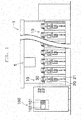
- an automatic winder (yarn winding machine) 1 includes a plurality of winding units 10 arranged in line, a doffing device 5, and a main control device 100.
- Each of the winding units 10 is adapted, while traversing a yarn 20 unwound from a yarn supplying bobbin 21, to wind the yarn 20 around a winding tube 22 supported by a cradle (winding tube supporting section) 23 to form a package 30.
- the doffing device 5 travels up to the position of the relevant winding unit 10, discharges the fully wound package 30 from the winding unit 10 (doffing operation), and supplies a winding tube 22, around which the yarn 20 is not wound, to the winding unit 10.
- the main control device 100 includes a machine setting section 101 and a machine display section 102.
- the machine setting section 101 can carry out setting with respect to each of the winding units 10 by enabling an operator to input predetermined set values, select an appropriate control method, and the like.
- the machine display section 102 can display a winding status of the yarn 20 in each of the winding units 10, content of trouble that occurred, and the like.
- a structure of the winding unit 10 will now be specifically described with reference to FIG. 2 .
- the winding unit 10 includes a yarn unwinding assisting device 12, a tension applying device 13, a yarn joining device 14, a clearer 15, and a winding section 18 arranged in such order from the yarn supplying bobbin 21 on a yarn travelling path between the yarn supplying bobbin 21 and the winding tube 22.
- the yarn unwinding assisting device 12 includes a regulating member 25 placed over a core tube of the yarn supplying bobbin 21.
- the yarn unwinding assisting device 12 assists in the unwinding of the yarn 20 from the yarn supplying bobbin 21 by lowering the regulating member 25 accompanying the unwinding of the yarn 20 from the yarn supplying bobbin 21.
- the regulating member 25 is brought into contact with a balloon formed at an upper part of the yarn supplying bobbin 21 by rotation and a centrifugal force of the yarn 20 unwound from the yarn supplying bobbin 21 to control the balloon to an appropriate size, thus assisting the unwinding of the yarn 20.
- a sensor (not illustrated) adapted to detect a chase portion (upper end of yarn layer) of the yarn supplying bobbin 21 is arranged in proximity to the regulating member 25.
- the regulating member 25 is lowered by, for example, an air cylinder (not illustrated).
- the tension applying device 13 applies a predetermined tension on the travelling yarn 20.
- a gate-type tension applying device in which movable comb teeth are arranged with respect to fixed comb teeth, is used as the tension applying device 13.
- the movable comb teeth can be swung by a rotary solenoid to cause the movable comb teeth to be in an engaged state or in a released state with the fixed comb teeth.
- a disk-type tension applying device for example, can also be used as the tension applying device 13.
- the yarn joining device 14 joins a yarn 20 (lower yarn) from the yarn supplying bobbin 21 and a yarn 20 (upper yarn) from the package 30 when yarn cutting is performed upon detection of a yarn defect by the clearer 15 or when yarn breakage occurs during the unwinding of the yarn 20 from the yarn supplying bobbin 21.
- the yarn joining device 14 can be of a mechanical type or of a type that uses fluid such as compressed air.
- the clearer 15 includes a sensor (not illustrated) adapted to detect, for example, the thickness of the yarn 20 and/or presence or absence of foreign substances in the yarn 20.
- the clearer 15 detects yarn defects, such as slub, by monitoring a yarn thickness signal output by the sensor.
- a cutter 39 is arranged in proximity to the clearer 15 to cut the yarn 20 immediately when the clearer 15 detects a yarn defect.
- a lower yarn catching member 33 is arranged below the yarn joining device 14, and adapted to catch the lower yarn from the yarn supplying bobbin 21 and guide the lower yarn to the yarn joining device 14.
- An upper yarn catching member (first catching member) 36 is arranged above the yarn joining device 14, and adapted to catch the upper yarn from the package 30 and guide the upper yarn to the yarn joining device 14.
- the lower yarn catching member 33 is swingable with a shaft 34 as a center.
- the upper yarn catching member 36 is swingable with a shaft 37 as a center.
- Each of the lower yarn catching member 33 and the upper yarn catching member 36 is connected to an appropriate negative pressure source (not illustrated).
- a suction flow can be generated at an opening of a distal end of the lower yarn catching member 33 to suck and catch the lower yarn with the lower yarn catching member 33.
- a suction flow can also be generated at an opening of a distal end of the upper yarn catching member 36 to suck and catch the upper yarn with the upper yarn catching member 36.
- At least one of the lower yarn catching member 33 or the upper yarn catching member 36 is not limited to a configuration of catching the yarn 20 by generating the suction flow, and may have a configuration of catching the yarn 20 using a member adapted to clamp the yarn 20.
- the winding section 18 includes the cradle 23 adapted to detachably support the winding tube 22, and a contact roller 29 adapted to be rotatable while making contact with an outer peripheral surface of the winding tube 22 or an outer peripheral surface of the package 30.
- the cradle 23 is supported to be swingable in a direction approaching the contact roller 29 and in a direction away from the contact roller 29. Increase in the diameter of the yarn layer of the package 30 accompanying the winding of the yarn 20 on the winding tube 22 can be absorbed by the swinging of the cradle 23.
- the contact roller 29 is arranged to oppose the winding tube 22 and to make contact with the winding tube 22 or the package 30. Therefore, by rotating the contact roller 29, the winding tube 22 or the package 30 can be rotated.
- a traverse groove (not illustrated) is formed on the outer peripheral surface of the contact roller 29, and the yarn 20 can be traversed within a predetermined width by the traverse groove. Accordingly, the winding unit 10 can wind the yarn 20 around the winding tube 22 while traversing the yarn 20 to form the package 30.
- the traverse method of the yarn 20 is not limited to the traverse groove, and may be a traverse mechanism (rod-type traverse device, arm-type traverse device, or belt-type traverse device) independently arranged from the contact roller 29.
- a traverse mechanism rod-type traverse device, arm-type traverse device, or belt-type traverse device
- the winding tube 22 or the package 30 may be driven and the contact roller 29 may be rotated following the rotation of the winding tube 22 or the package 30.
- a yarn withdrawal device 28 is arranged in proximity to the contact roller 29 and the package 30.
- the yarn withdrawal device 28 is a device adapted to withdraw the yarn 20 from the package 30.
- the yarn withdrawal device 28 injects air to generate an airflow to withdraw the yarn 20 from the package 30.
- a case in which the yarn 20 is disconnected includes, for example, a case in which the yarn 20 is broken and/or a case in which the yarn 20 is cut with a cutter 39 upon detection of a yarn defect by the clearer 15, and the like.
- the timing for the yarn withdrawal device 28 to start the injection of air may be when the package 30 is rotating in a reverse rotational direction (unwinding direction), which is a direction opposite to the winding direction, or when the package 30 stops rotating in the winding direction and starts rotating in the reverse rotational direction.
- the yarn withdrawal device 28 may inject air while the package 30 decelerates from the state of rotating in the winding direction to prevent the yarn 20 from attaching to the package 30.
- the yarn withdrawal device 28 can more reliably withdraw the yarn 20 from the package 30.
- the winding section 18 reversely rotates the package 30.
- the reverse rotation of the package 30 is stopped, and the package 30 is rotated several times in the winding direction.
- the airflow may be injected from the yarn withdrawal device 28.
- the probability of withdrawal of the yarn 20 from the package 30 increases.
- the yarn 20 (upper yarn) withdrawn from the package 30 in such a manner is caught by the upper yarn catching member 36, and guided to the yarn joining device 14 (second target position).
- the upper yarn guided to the yarn joining device 14 is joined with the lower yarn caught and guided by the lower yarn catching member 33 by the yarn joining device 14.
- the upper yarn catching member 36 is set such that the suction force when sucking and catching the yarn 20 becomes greater than the suction force when guiding the sucked yarn 20 to the yarn joining device 14. Thus, the probability of failing in catching at the time of catching the yarn 20 can be lowered, and the probability of yarn breakage at the time of guiding the yarn 20 can be lowered.
- the suction force of the upper yarn catching member 36 may be a constant suction force from the time of catching to the time of guiding.
- a structure of the yarn withdrawal device 28 will be hereinafter described in detail with reference to FIGS. 3 to 6 .
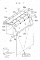
- the yarn withdrawal device 28 has a substantially rectangular parallelpiped shape, and includes a first outer surface 28a and a second outer surface 28b. As illustrated in FIG. 5 , the yarn withdrawal device 28 is arranged such that the first outer surface 28a and the second outer surface 28b are located in proximity to the package 30. The first outer surface 28a is arranged at an angle along the surface of the package 30 (angle close to a tangential direction of the package 30). The yarn withdrawal device 28 detaches the yarn 20 from the package 30 and feeds the yarn 20 toward the second outer surface 28b by the airflow (specifically, first airflow 91 and second airflow 92 to be described later) generated on the first outer surface 28a to withdraw the yarn 20 from the package 30.
- the airflow specifically, first airflow 91 and second airflow 92 to be described later
- the second outer surface 28b is arranged at an angle to lie along a radial direction of the package 30.
- the second outer surface 28b is located on a downstream side of the first outer surface 28a in a flow direction of the airflow.
- the yarn withdrawal device 28 guides the yarn 20 detached from the package 30 along the second outer surface 28b to an opening (catching position, first target position) of the upper yarn catching member 36 arranged at a catching position (position of chain double dashed line in FIG. 2 ) .
- the yarn withdrawal device 28 includes a main body part 40, a first injecting section 50, and a second injecting section 60.
- package axial direction an axial direction of the package 30 (winding tube 22) is referred to as "package axial direction”.
- package axial direction a direction along the first outer surface 28a (more precisely, a direction along a portion not formed with an inclined surface) is referred to as a "first direction”.
- first direction a direction along the first outer surface 28a
- second direction A direction perpendicular to the first direction when seen in the package axial direction.
- the main body part 40 is attached in proximity to the winding section 18 by an attachment mechanism (not illustrated).
- the main body part 40 may be movable between a position in proximity to the package 30 and a position spaced apart from the package 30.
- An air supplying tube 81 adapted to supply compressed air is attached to the main body part 40.
- the main body part 40 is provided with a first air supplying path 41, a second air supplying path 42, a curved surface 43, and a guiding section 45.
- the first air supplying path 41 and the second air supplying path 42 are spaces formed inside the main body part 40, and are paths through which the compressed air supplied through the air supplying tube 81 flows.
- the compressed air flows along the second direction (specifically, toward a side where the first injecting section 50 and the second injecting section 60 are arranged) through the first air supplying path 41 and the second air supplying path 42.
- the first air supplying path 41 is formed on one side (specifically, a side close to the second outer surface 28b) of the second air supplying path 42 in the first direction.
- the compressed air supplied through the first air supplying path 41 is injected from the first injecting section 50 to generate the first airflow 91.
- the compressed air supplied through the second air supplying path 42 is injected from the second injecting section 60 to generate the second airflow 92.
- the first air supplying path 41 and the second air supplying path 42 are not divided into different sections by a partition and the like, and are connected. Therefore, the first airflow 91 and the second airflow 92 have a common air supplying path.
- the curved surface 43 is a surface exposed to the exterior of the yarn withdrawal device 28.
- the curved surface 43 is a surface curved to smoothly connect the first outer surface 28a and the second outer surface 28b and to project outward.
- the guiding section 45 is provided on the second outer surface 28b.
- the guiding section 45 is adapted to guide the yarn 20 withdrawn from the package 30 by the yarn withdrawal device 28 toward the first target position.
- the guiding section 45 includes two members protruding out in the first direction from respective ends in the package axial direction (package width direction) of the second outer surface 28b. One of the two members is provided with a first guiding surface 45a, and the other member is provided with a second guiding surface 45b.
- the first guiding surface 45a and the second guiding surface 45b are arranged to face toward a center side in the package width direction so as to face one another.
- the first guiding surface 45a and the second guiding surface 45b are surfaces substantially perpendicular to the second outer surface 28b.
- An interval between the first guiding surface 45a and the second guiding surface 45b increases toward the first outer surface 28a (toward the curved surface 43). In other words, the interval between the first guiding surface 45a and the second guiding surface 45b becomes narrower toward the downstream side in the guiding direction of the yarn 20.
- the first guiding surface 45a and the second guiding surface 45b are respectively inclined so as to become closer toward the center side in the package axial direction.
- the first target position is not the center in the package axial direction, but is closer to the first guiding surface 45a (L1 ⁇ L2 of FIG. 3 ) in the present embodiment.
- inclination angles of the first guiding surface 45a and the second guiding surface 45b of the present embodiment are different.
- a first length (thickness, width) of the guiding section 45 is a length between the first guiding surface 45a and the other end of the guiding section 45 located opposite to the center in the package axial direction
- a second length (thickness, width) of the guiding section 45 is a length between the second guiding surface 45b and the other end of the other guiding section 45 located opposite to the center in the package axial direction, when comparing at positions located downstream from an upstream end of the respective guiding section 45 by a predetermined length in the guiding direction of the yarn 20, the first length is shorter than the second length.
- the inclination angles of the first guiding surface 45a and the second guiding surface 45b may be the same.
- the guiding section 45 may be a different member to be attached to the main body part 40, or may be integrally configured with the main body part 40.
- the first injecting section 50 includes a first spacer portion 51 and a first cover portion 52.
- the first spacer portion 51 and the first cover portion 52 are plate-shaped members, which configure one part of the first outer surface 28a and are attached to the main body part 40 in the same direction (specifically, so that the thickness direction (height direction) becomes the same as the second direction).
- the first spacer portion 51 is formed with a cutout 51a, air passing holes 51b, and attachment holes 51c.
- the cutout 51a is a portion in which an end in the first direction (specifically, an end on the second outer surface 28b side) is cut out to a rectangular shape.
- the cutout 51a is formed at a position overlapping the first air supplying path 41 when seen in the second direction (a flow direction of compressed air). Thus, the compressed air supplied through the first air supplying path 41 passes the cutout 51a.
- the air passing holes 51b are through-holes formed on the other side (specifically, an opposite side of the second outer surface 28b, upstream in the flow direction of the second airflow 92) of the cutout 51a in the first direction.
- the air passing holes 51b are formed in plurals and arranged along the package axial direction.
- the air passing holes 51b are formed at positions overlapping the second air supplying path 42 when seen in the second direction. Thus, the compressed air supplied through the second air supplying path 42 passes the air passing holes 51b.
- the attachment holes 51c are through-holes for attaching the first spacer portion 51 to the main body part 40.
- a plurality of (five in the present embodiment) attachment holes 51c are arranged alternately with the air passing holes 51b, and furthermore, a plurality of (five in the present embodiment) attachment holes 51c are formed on the other side in the first direction of the first spacer portion 51.
- the air passing hole 51b is larger than the attachment hole 51c.
- the first cover portion 52 is formed with a plurality of attachment holes 52c.
- the attachment holes 52c are also through-holes.
- a plurality of (five in the present embodiment) attachment holes 52c are arranged alternately with the air passing holes 52b, and furthermore, a plurality of (five in the present embodiment) attachment holes 52c are formed on the other side in the first direction of the first cover portion 52.
- the second spacer portion 61 is formed with a plurality of attachment holes 61b along the longitudinal direction.
- the second cover portion 62 is formed with a plurality of attachment holes 62c along the longitudinal direction.
- the attachment holes 61b and the attachment holes 62c are through-holes.
- a plurality of attachment holes are formed in the main body part 40.
- a plurality of (five in the present embodiment) attachment holes are arranged alternately with the second air supplying path 42, and furthermore, a plurality of (five in the present embodiment) attachment holes are formed on the other side in the first direction of the main body part 40.
- a fixing tool such as a bolt is inserted with positions of following holes aligned, i.e. the plurality of attachment holes of the main body part 40 (attachment holes arranged alternately with the second air supplying path 42), the attachment holes 51c of the first spacer portion 51 (attachment holes arranged alternately with the air passing holes 51b), and the attachment holes 51 of the first cover portion 52 (attachment holes arranged alternately with the air passing holes 52b).
- a fixing tool such as a bolt is inserted with positions of following holes aligned, i.e.
- the attachment holes of the main body part 40 the attachment holes 51c of the first spacer portion 51, the attachment holes 52c of the first cover portion 52, the attachment holes 61b formed in the second spacer portion 61, and the attachment holes 62c formed in the second cover portion 62.
- the first spacer portion 51 is attached to the main body part 40 with the first cover portion 52, the second injecting section 60, and the like. Since the main body part 40, the first injecting section 50, and the second injecting section 60 are fixed with a plurality of fixing tools, air leakage can be prevented.
- the first cover portion 52 is attached to the main body part 40 with the first spacer portion 51 therebetween and so as to cover the first spacer portion 51. Since the cutout 51a is formed in the first spacer portion 51, the first cover portion 52 is attached with respect to the main body part 40 with a spacing therebetween. Thus, a gap is formed on the inner side of the first cover portion 52, and this gap serves as the first slit 50a. Therefore, the longitudinal direction of the first slit 50a is the same as the package axial direction. The width (height, length in a shorter direction) of the first slit 50a is dependent on the thickness of the first spacer portion 51.
- the thickness of the first spacer portion 51 is preferably greater than or equal to 0.01 mm and less than or equal to 5 mm, and more preferably greater than or equal to 0.03 mm and less than or equal to 2 mm, or greater than or equal to 0.03 mm and less than or equal to 0.2 mm.
- the compressed air supplied through the first air supplying path 41 passes through the cutout 51a and is guided by the first cover portion 52 (specifically, a surface facing the main body part 40 side, an inner surface) to be injected from the first slit 50a.
- the first airflow 91 is thereby generated.
- the first airflow 91 mainly flows along the curved surface 43, and then flows along the second outer surface 28b.
- the first airflow 91 detaches the yarn 20 from the package 30, and guides the yarn 20 detached from the package 30.
- the first cover portion 52 is formed with a first inclined surface 52a, the air passing holes 52b, and the attachment holes 52c.
- the first inclined surface 52a is formed on a surface (outer surface) facing the side opposite to the main body part 40.
- the first inclined surface 52a is formed from the first slit 50a to the other side of the first direction.
- the first inclined surface 52a is inclined toward one side of the first direction to approach the first spacer portion 51 (an inner side of the main body part 40).
- the first inclined surface 52a is inclined so as to be continuous to a basal end of the flow of the first airflow 91. According to such a configuration, a first auxiliary airflow 93 ( FIG.
- the yarn 20 of the package 30 can be more reliably withdrawn while reducing the flow volume of the airflow injected from the first slit 50a.
- the air passing holes 52b are through-holes formed in plurals and arranged in the package axial direction.
- the air passing holes 52b are formed at a position overlapping the second air supplying path 42 and the air passing holes 51b when seen in the second direction.
- the compressed air supplied through the second air supplying path 42 passes through the air passing holes 51b and the air passing holes 52b.
- the second injecting section 60 includes a second spacer portion 61 and a second cover portion 62.
- the second spacer portion 61 and the second cover portion 62 are plate-shaped members, and configure one part of the first outer surface 28a.
- the second spacer portion 61 and the second cover portion 62 are attached to the main body part 40 in the same direction (specifically, so that the thickness direction (height direction) becomes the same as the second direction) with the first injecting section 50 therebetween.
- the second spacer portion 61 is formed with a cutout 61a and attachment holes 61b.
- the cutout 61a is a portion in which an end in the first direction (specifically, an end on the second outer surface 28b side, an end on the first slit 50a side) is cut out to a rectangular shape.
- the cutout 61a is formed at a position overlapping the second air supplying path 42 when seen in the second direction. Thus, the compressed air supplied through the second air supplying path 42, the air passing holes 51b, and the air passing holes 52b passes through the cutout 61a.
- the thickness (height) of the second spacer portion 61 is preferably greater than or equal to 0.01 mm and less than or equal to 5 mm, and more preferably greater than or equal to 0.03 mm and less than or equal to 2 mm, or greater than or equal to 0.03 mm and less than or equal to 0.2 mm.
- the second cover portion 62 is attached to the main body part 40 with the second spacer portion 61 therebetween and so as to cover the second spacer portion 61. Since the cutout 61a is formed in the second spacer portion 61, the second cover portion 62 is attached with respect to the first cover portion 52 with a spacing therebetween. Thus, a gap is formed on the inner side of the second cover portion 62, and this gap serves as the second slit 60a.
- the compressed air supplied through the second air supplying path 42 and the like passes through the cutout 61a, and is guided by the second cover portion 62 (specifically, a surface facing the main body part 40 side, an inner surface) to be injected from the second slit 60a.
- the second airflow 92 is thereby generated.
- the second cover portion 62 is formed with a second inclined surface 62a, an injection direction correcting surface 62b, and the attachment holes 62c.
- the second inclined surface 62a is formed on a surface (an outer surface) facing the side opposite to the main body part 40.
- the second inclined surface 62a is formed from the second slit 60a to the other side of the first direction.
- the second inclined surface 62a is inclined toward one side of the first direction to approach the second spacer portion 61 (an inner side of the main body part 40).
- the second inclined surface 62a is inclined so as to be continuous to a basal end of the flow of the second airflow 92. According to such a configuration, a second auxiliary airflow 94 is easily generated, and thus the air around the second slit 60a can be effectively drawn into the second airflow 92.
- the injection direction correcting surface 62b is an inner surface of the second cover portion 62, and is particularly an inclined surface formed in proximity to the second slit 60a. As illustrated in FIG. 6 , the injection direction correcting surface 62b is a surface inclined to be away from the main body part 40, the second spacer portion 61 and the like (so that the height of the second slit 60a increases) toward the second slit 60a. In other words, the injection direction correcting surface 62b is an inclined surface formed so that the plate thickness becomes thinner toward the second slit 60a, assuming that the outer surface (second inclined surface 62a) is flat.
- the second airflow 92 generated by the compressed air injected from the second slit 60a is guided by the injection direction correcting surface 62b so as to mainly flow away from the first cover portion 52 and toward the package 30.
- the second slit 60a is arranged upstream of the first inclined surface 52a and not on the first inclined surface 52a of the first cover portion 52.
- the second airflow 92 is less likely to flow along the first inclined surface 52a toward the second outer surface 28b, whereby the second airflow 92 easily flows toward the package 30.
- the second airflow 92 is an airflow flowing toward the package 30 and thus easily hits the package 30. Therefore, the yarn 20 is easily detached from the package 30.
- the second airflow 92 flows in a direction different from the first airflow 91, and thus even if the yarn 20 cannot be detached from the package 30 with the first airflow 91, the yarn 20 may be detached from the package 30 with the second airflow 92. Therefore, the probability of succeeding in the withdrawal of the yarn 20 can be increased compared to when generating only the first airflow 91.
- the yarn withdrawal device 28 In order to effectively act the first airflow 91 and the second airflow 92 on the package 30, the yarn withdrawal device 28 needs to be arranged near the package 30.
- the yarn withdrawal device 28 since the curved surface 43 is formed, the yarn withdrawal device 28 is less likely to interfere with the package 30 compared to the configuration in which the curved surface 43 is a right angle. Thus, the yarn withdrawal device 28 can be arranged near the package 30.
- the yarn withdrawal device 28 becomes less likely to interfere with the package 30.
- the yarn withdrawal device 28 can be arranged near the package 30.
- a movable member adapted to move the yarn withdrawal device 28 to a position dependent on the diameter of the package 30 is preferably arranged.
- the first airflow 91 and the second airflow 92 can be more effectively acted by arranging, in particular, the first slit 50a and the second slit 60a of the yarn withdrawal device 28 near the package 30.
- the second slit 60a is located, in the first direction, upstream of the first slit 50a in the flow direction of the second airflow 92.
- the second slit 60a is located, in the second direction, on a side more distant from the main body part 40 (a side close to the package 30) than the first slit 50a.
- first slit 50a and the package 30 becomes longer from the first slit 50a toward the upstream side in the flow direction of the second airflow 92 along the first direction, but the second slit 60a is provided at a position protruding toward the package 30 side in the second direction to compensate for such a positional relationship.
- the first slit 50a and the second slit 60a are arranged in a layout that lies along the surface of the package 30. Therefore, both the first slit 50a and the second slit 60a can be arranged near the package 30.
- the yarn withdrawal device 28 of the present embodiment includes the first injecting section 50 and the second injecting section 60.
- the first injecting section 50 is formed with the first slit 50a, and adapted to generate the first airflow 91 by air being injected from the first slit 50a.
- the second injecting section 60 is formed with the second slit 60a along a longitudinal direction of the first slit 50a and adapted to generate the second airflow 92 by air being injected from the second slit 60a, the second airflow being an airflow flowing in a direction different from a flow direction of the first airflow 91.
- the airflows in different flow directions are respectively generated from the two slits, whereby the airflow can be easily acted on the package 30 in a wide range.
- the probability of succeeding in the withdrawal of the yarn 20 from the package 30 can be increased.
- the yarn withdrawal device 28 of the present embodiment includes the main body part 40, the first injecting section 50, and the second injecting section 60.
- the first injecting section 50 includes the first spacer portion 51 and the first cover portion 52.
- the first slit 50a is formed by the first spacer portion 51 being arranged between the first cover portion 52 and the main body part 40, and the first airflow 91 is generated by air being injected from the first slit 50a.
- the second injecting section 60 includes the second spacer portion 61 and the second cover portion 62.
- the second slit 60a is formed by the second spacer portion 61 being arranged between the second cover portion 62 and the first cover portion 52, and the second airflow 92 is generated by air being injected from the second slit 60a.
- the airflows are generated respectively from the two slits formed at different positions, whereby the airflows in different flow directions easily act on the package 30. As a result, the probability of succeeding in the withdrawal of the yarn 20 from the package 30 can be increased.
- a thickness of at least one of the first spacer portion 51 and the second spacer portion 61 is preferably greater than or equal to 0.01mm and less than or equal to 5mm.
- the success rate of the withdrawal of the yarn 20 from the package 30 can be sufficiently increased while reducing the amount of air supplied to the yarn withdrawal device 28.
- the yarn withdrawal device 28 of the present embodiment is provided with at least one of (specifically, both) the first inclined surface 52a and the second inclined surface 62a.
- the first inclined surface 52a is inclined so as to be continuous to a basal end of a flow of the first airflow 91 and continuous to the first slit 50a
- the second inclined surface 62a is inclined so as to be continuous to a basal end of a flow of the second airflow 92 and continuous to the second slit 60a. Either one of the first inclined surface 52a or the second inclined surface 62a may be omitted.
- the air around the first slit 50a and/or the second slit 60a can be taken into the first airflow 91 and/or the second airflow 92, whereby the yarn 20 from the package 30 can be withdrawn while reducing the flow volume of the airflow supplied to the yarn withdrawal device 28.
- a surface adapted to guide air before being injected from the second slit 60a includes an injection direction correcting surface 62b inclined such that a height of the second slit 60a increases towards an end of the second slit 60a from which the second airflow 92 is injected.
- the second airflow 92 flows away from the outer surface (first outer surface 28a) of the yarn withdrawal device 28, whereby the second airflow 92 easily hits the package 30.
- the yarn withdrawal device 28 of the present embodiment includes a guiding section 45 arranged downstream in the flow direction of the first airflow 91, and adapted to guide the yarn 20 withdrawn from the package 30 toward the center in the longitudinal direction of the first slit 50a.
- the position of the yarn 20 withdrawn from the package 30 by the yarn withdrawal device 28 is defined, and hence a next process can be easily carried out.
- the yarn withdrawal device 28 of the present embodiment includes the first outer surface 28a and the second outer surface 28b.
- the first outer surface 28a is provided with the first slit 50a and the second slit 60a.
- the second outer surface 28b is provided downstream in the flow direction of the first airflow 91 with respect to the first outer surface 28a.
- the guiding section 45 is provided on the second outer surface 28b.
- first outer surface 28a for withdrawing the yarn 20 from the package 30 and a surface (second outer surface 28b) for guiding the withdrawn yarn 20 can be separated, whereby the size of the yarn withdrawal device 28 can be reduced.
- the first guiding surface 45a and the second guiding surface 45b are formed on the guiding section 45 and arranged to protrude from the second outer surface 28b and to face one another. An interval between the first guiding surface 45a and the second guiding surface 45b becomes wider toward the first outer surface 28a.
- the yarn 20 withdrawn from the package 30 is easily guided by the guiding section 45. Furthermore, since the yarn 20 is guided to a narrow range by the guiding section 45, the next process can be easily carried out.
- the yarn withdrawal device 28 of the present embodiment includes the curved surface 43 smoothly connecting the first outer surface 28a and the second outer surface 28b and being curved to project outward.
- the second airflow 92 thus easily flows in a direction different from the flow of the first airflow 91.
- the automatic winder 1 of the present embodiment includes the yarn withdrawal device 28 and the winding section 18.
- the winding section 18 is adapted to rotate the winding tube 22 in the winding direction to form the package 30 by winding the yarn 20.
- the flow direction of the first airflow 91 is set to guide the yarn 20 withdrawn from the package 30 to the first target position, and the flow direction of the second airflow 92 is set towards the package 30.
- the functions of the first airflow 91 and the second airflow 92 can be differed from each other, whereby the yarn 20 can be withdrawn from the package 30 and the withdrawn yarn 20 can be guided to the first target position (catching position).
- the second slit 60a is formed downstream of the first slit 50a in the reverse rotational direction of the package 30.
- the yarn 20 is detached from the package 30 or the detaching of the yarn 20 is assisted by the second airflow 92, and the detached yarn 20 can be fed downstream by the first airflow 91.
- the automatic winder 1 of the present embodiment includes the upper yarn catching member 36 adapted to catch the yarn 20 withdrawn by the yarn withdrawal device 28.
- the first target position is a catching position of the upper yarn catching member 36.
- the success rate of the catching of the yarn 20 by the upper yarn catching member 36 can be increased.
- the upper yarn catching member 36 catches the yarn 20 by sucking the yarn 20, and guides the caught yarn 20 to the second target position (yarn joining device 14).
- the suction force of the upper yarn catching member 36 is set such that the suction force when catching the yarn 20 becomes greater than the suction force when guiding the sucked yarn 20 to the second target position.
- the probability of failing in catching of the yarn 20 thus can be lowered, and the probability of yarn breakage at the time of guiding the yarn 20 can be lowered.
- the yarn joining device 14 is provided for every winding unit 10.
- a service vehicle movable in a direction in which the winding units 10 are arranged may be provided, and the yarn joining device 14 may be provided in the service vehicle.
- the yarn withdrawal device 28 may be arranged on the service vehicle.
- the upper yarn catching member 36 and the lower yarn catching member 33 may also be arranged on the service vehicle.
- the yarn withdrawal device 28 may be arranged on the doffing device 5 (service vehicle). In this case, the doffing device 5 may withdraw the yarn 20 from the package 30 by the yarn withdrawal device 28 when the doffing device 5 is not carry out the doffing operation.
- the doffing device 5 may withdraw the yarn 20 from the package 30 of another winding unit 10 by the yarn withdrawal device 28.
- the yarn joining device 14 may be arranged on each winding unit 10.
- the upper yarn catching member 36 may be arranged on either one of the doffing device 5 or each winding unit 10.
- the cutout 51a, the air passing holes 51b, the air passing holes 52b, and the cutout 61a may have shapes other than the shapes illustrated in the embodiment described above as long as the compressed air can pass therethrough.
- the cutout 51a and the cutout 61a may be formed in a concave-convex shape (comb tooth shape).
- the air passing holes 51b and the air passing holes 52b may be one long hole that is long in the package axial direction.
- first injecting section 50 and the second injecting section 60 are integrally configured by being attached to the same main body part 40. Instead, the first injecting section 50 and the second injecting section 60 may be separately configured.
- the yarn 20 withdrawn from the package 30 by the yarn withdrawal device 28 is guided to the yarn joining device 14 via the upper yarn catching member 36.
- the yarn 20 from the package 30 may be guided to the yarn joining device 14 via still another catching member (second catching member) after the upper yarn catching member 36.
- the second catching member is, for example, a tubular member capable of sucking the yarn 20, and is a member movable between a position of catching the yarn 20 from the upper yarn catching member 36 and a position of guiding the caught yarn 20 to the yarn joining device 14.
- the yarn withdrawal device 28 and the upper yarn catching member 36 may be arranged on the service vehicle, and the second catching member, the yarn joining device 14, and the lower yarn catching member 33 may be arranged on each winding unit 10.
- the final guiding destination of the yarn 20 may not be the yarn joining device 14, and may be a different position.
- the yarn withdrawal device 28 of the present invention is not limited to being arranged in the automatic winder and can also be applied to other yarn winding machines, such as re-winding machines and fine spinning machines (e.g., air spinning machines, open-end spinning machines, etc.).
- the yarn withdrawal device 28 can also be applied to a fine spinning machine having a configuration in which a yarn joining device is arranged for every winding unit as described above.
- the yarn withdrawal device 28 can also be applied to a fine spinning machine having a configuration in which one yarn joining device is arranged for every predetermined number of winding units.
- the air spinning machine includes a draft device adapted to draft a fiber bundle with a plurality of pairs of draft rollers, a spinning device adapted to spin the fiber bundle with a whirling airflow to produce a yarn, and a winding device adapted to wind the yarn to form a package.
- the winding device may be arranged on the upper side or the draft device may be arranged on the upper side in the machine height direction.
- the yarn joining device of the fine spinning machine is not limited to a mechanical configuration (e.g., knotter) or a configuration using fluid such as compressed air (splicer), and may be a piecer.
- the yarn withdrawal device 28 When the yarn joining device is a piecer, the yarn 20 withdrawn from the package 30 by the yarn withdrawal device 28 is reversely fed to the spinning device.
- the yarn withdrawal device 28 When the yarn withdrawal device 28 is arranged on the fine spinning machine, the yarn withdrawal device 28 may be arranged on the doffing cart. In such alternative embodiments as well, the yarn withdrawal device 28 may be configured as in the above-described embodiment and/or alternative embodiment.
Landscapes
- Engineering & Computer Science (AREA)
- Textile Engineering (AREA)
- Replacing, Conveying, And Pick-Finding For Filamentary Materials (AREA)
- Yarns And Mechanical Finishing Of Yarns Or Ropes (AREA)
- Spinning Or Twisting Of Yarns (AREA)
Abstract
Description
- The present invention mainly relates to a yarn withdrawal device adapted to withdraw a yarn from a package.
- A yarn withdrawal device arranged in proximity to a package and adapted to withdraw a yarn of the package to perform, for example, yarn joining operation is conventionally known. This type of yarn withdrawal device is disclosed in Japanese Patent Application Laid-open No.
2014-125348 H5-5769 2426724 -
Patent document 1 discloses a yarn withdrawal device formed with one slit for injecting compressed air. Airflow generated by the compressed air injected from the slit flows along an outer wall surface of the yarn withdrawal device. Since the outer wall surface is arranged in proximity to the package, a yarn is withdrawn from the package by the airflow. - Patent documents 2 and 3 disclose yarn end withdrawal devices having a structure in which two nozzle tubes are arranged in an axial direction of the package. A plurality of nozzle holes are formed in each of the two nozzle tubes. A yarn entangled with the surface of the package can be detached (separated, removed, lifted) from the package by injecting the air from such nozzle holes.
- However, in the yarn withdrawal device of
patent document 1, a range in which the airflow is acted on the package is not sufficient as only one slit is provided. As a result, there is a possibility that the yarn may not be withdrawn from the package. Furthermore, in patent documents 2 and 3, the strength of the airflow may become uneven in the axial direction of the package as the air is injected from the nozzle holes. As a result, there is a possibility that the yarn may not be withdrawn from the package. - It is a main object of the present invention to provide a yarn withdrawal device having a high possibility of succeeding in withdrawal of a yarn from a package.
- According to a first aspect of the present invention, a yarn withdrawal device having the following structure is provided. That is, the yarn withdrawal device includes a first injecting section and a second injecting section. The first injecting section is formed with a first slit and adapted to generate a first airflow by air being injected from the first slit. The second injecting section is formed with a second slit along a longitudinal direction of the first slit and adapted to generate second airflow by air being injected from the second slit, the second airflow being an airflow flowing in a direction different from a direction of the first airflow.
- Thus, the airflows along different flow directions are generated from the two slits, whereby the airflow can be easily acted on the package in a wide range. As a result, the probability of succeeding in withdrawal of a yarn from a package can be increased.
- According to a second aspect of the present invention, a yarn withdrawal device having the following structure is provided. That is, the yarn withdrawal device includes a main body part, a first injecting section, and a second injecting section. The first injecting section includes a first spacer portion and a first cover portion, a first slit being formed by the first spacer portion being arranged between the first cover portion and the main body part, the first injecting section being adapted to generate a first airflow by air being injected from the first slit. The second injecting section includes a second spacer portion and a second cover portion, a second slit being formed by the second spacer portion being arranged between the second cover portion and the first cover portion, the second injecting section being adapted to generate a second airflow by air being injected from the second slit.
- Thus, the airflow is generated from each of the two slits formed at different positions, whereby the airflows along different flow directions can easily act on the package. As a result, the probability of succeeding in withdrawal of a yarn from a package can be increased.
- In the yarn withdrawal device, a thickness of at least one of the first spacer portion and the second spacer portion is preferably greater than or equal to 0.01mm and less than or equal to 5mm.
- Thus, the success rate of the withdrawal of the yarn from the package can be sufficiently increased while reducing the amount of air supplied to the yarn withdrawal device.
- The yarn withdrawal device preferably includes at least one of a first inclined surface and a second inclined surface, the first inclined surface being inclined so as to be continuous to a basal end of a flow of the first airflow and continuous to the first slit, and the second inclined surface being inclined so as to be continuous to a basal end of a flow of the second airflow and continuous to the second slit.
- Thus, the air around the first slit and/or the second slit can be drawn into the first airflow and/or the second airflow, whereby the yarn from the package can be withdrawn while reducing the amount of air supplied to the yarn withdrawal device.
- In the yarn withdrawal device, a surface adapted to guide air before being injected from the second slit preferably has an injection direction correcting surface inclined such that a height of the second slit increases towards an end of the second slit from which the second airflow is injected.
- Thus, since the second airflow flows away from the outer surface of the yarn withdrawal device, the second airflow can easily hit the package.
- The yarn withdrawal device preferably includes a guiding section arranged downstream in a flow direction of the first airflow and adapted to guide the yarn withdrawn from the package towards center in a longitudinal direction of the first slit.
- The position of the yarn withdrawn from the package by the yarn withdrawal device is thereby defined, and thus a next process can be easily carried out.
- The yarn withdrawal device preferably has the following structure. That is, the yarn withdrawal device includes a first outer surface and a second outer surface. The first outer surface is provided with the first slit and the second slit. The second outer surface is arranged downstream in the flow direction of the first airflow with respect to the first outer surface. The guiding section is provided on the second outer surface.
- Thus, the surface (first outer surface) for withdrawing the yarn from the package, and the surface (second outer surface) for guiding the withdrawn yarn can be separated, whereby the size of the yarn withdrawal device can be reduced.
- The yarn withdrawal device preferably has the following structure. That is, a first guiding surface and a second guiding surface are formed on the guiding section and arranged to protrude from the second outer surface and to face one another. An interval between the first guiding surface and the second guiding surface increases towards the first outer surface.
- Thus, the yarn withdrawn from the package is easily guided by the guiding section. Furthermore, as the yarn is guided to a narrow range by the guiding section, the next process can be easily carried out.
- The yarn withdrawal device preferably includes a curved surface smoothly connecting the first outer surface and the second outer surface and being curved to project outward. Thus, the second airflow easily flows in the direction different from the flow of the first airflow.
- According to a third aspect of the present invention, a yarn winding machine having the following configuration is provided. That is, the yarn winding machine includes the yarn withdrawal device and a winding section. The winding section is adapted to rotate a winding tube in a winding direction to form the package by winding the yarn. A longitudinal direction of the first slit is along an axial direction of the package. Thus, the yarn can be withdrawn from the package by the yarn withdrawal device.
- The yarn winding machine preferably has the following structure. That is, a flow direction of the first airflow is set to guide the yarn withdrawn from the package to a first target position, and a flow direction of the second airflow is set towards the package.
- Thus, since the functions of the first airflow and the second airflow can be differed from each other, the yarn can be withdrawn from the package and the withdrawn yarn can be guided to the first target position.
- The yarn winding machine preferably has the following structure. That is, the winding section is configured to rotate the package also in a reverse rotational direction, which is a direction opposite to the winding direction. The second slit is formed downstream of the first slit in the reverse rotational direction of the package.
- Thus, the yarn is detached (separated, removed, lifted) from the package or the detaching of the yarn is assisted by the second airflow, and the detached yarn can be fed downstream by the first airflow.
- The yarn winding machine preferably has the following structure. That is, the yarn winding machine includes a first catching member adapted to catch the yarn withdrawn from the package by the yarn withdrawal device. The first target position is a catching position of the first catching member.
- The success rate of the catching of the yarn by the first catching member thus can be increased.
- The yarn winding machine preferably has the following structure. That is, the first catching member is adapted to catch the yarn by sucking the yarn and to guide the caught yarn to a second target position. A suction force of the first catching member is set such that a suction force when catching the yarn is greater than a suction force when guiding the yarn to the second target position.
- This can lower the probability of failing in catching of the yarn and can also lower the probability of yarn breakage when guiding the yarn.
- The yarn winding machine preferably includes a second catching member adapted to receive the caught yarn from the first catching member and to guide the yarn to a third target position,
- Thus, the yarn can be guided to the target position while reducing the size and/or movable range of each catching member.
- The yarn winding machine preferably has the following structure. That is, the yarn winding machine includes a plurality of winding units and a service vehicle. The winding units each includes at least the winding section. The service vehicle is adapted to be movable with respect to the plurality of the winding units. The service vehicle includes the yarn withdrawal device.
- Thus, the cost of the yarn winding machine can be reduced by arranging one yarn withdrawal device with respect to the plurality of winding units.
- The yarn winding machine preferably has the following structure. That is, the yarn winding machine includes a plurality of winding units, each including at least the winding section. The yarn withdrawal device is arranged in each of the plurality of the winding units.
- Thus, when the withdrawal of the yarn from the package becomes necessary in a winding unit, the yarn can be immediately withdrawn from the package, and hence the production efficiency of the package can be enhanced.
-
-
FIG. 1 is a front view of an automatic winder according to an embodiment of the present invention; -
FIG. 2 is a side view illustrating a schematic structure of a winding unit; -
FIG. 3 is a perspective view of an outer appearance of a yarn withdrawal device; -
FIG. 4 is an exploded perspective view of the yarn withdrawal device; -
FIG. 5 is a side view of the yarn withdrawal device and a package; and -
FIG. 6 is a side cross-sectional view of a proximity of a first slit and a second slit. - Exemplary embodiments of the present invention will be described in detail below with reference to the accompanying drawings.
- As illustrated in
FIG. 1 , an automatic winder (yarn winding machine) 1 includes a plurality of windingunits 10 arranged in line, adoffing device 5, and amain control device 100. - Each of the winding
units 10 is adapted, while traversing ayarn 20 unwound from ayarn supplying bobbin 21, to wind theyarn 20 around a windingtube 22 supported by a cradle (winding tube supporting section) 23 to form apackage 30. - When the
package 30 is fully wound in any of the windingunits 10, thedoffing device 5 travels up to the position of the relevant windingunit 10, discharges the fully woundpackage 30 from the winding unit 10 (doffing operation), and supplies a windingtube 22, around which theyarn 20 is not wound, to the windingunit 10. - The
main control device 100 includes amachine setting section 101 and amachine display section 102. Themachine setting section 101 can carry out setting with respect to each of the windingunits 10 by enabling an operator to input predetermined set values, select an appropriate control method, and the like. Themachine display section 102 can display a winding status of theyarn 20 in each of the windingunits 10, content of trouble that occurred, and the like. - A structure of the winding
unit 10 will now be specifically described with reference toFIG. 2 . - The winding
unit 10 includes a yarnunwinding assisting device 12, atension applying device 13, ayarn joining device 14, a clearer 15, and a windingsection 18 arranged in such order from theyarn supplying bobbin 21 on a yarn travelling path between theyarn supplying bobbin 21 and the windingtube 22. - The yarn
unwinding assisting device 12 includes a regulatingmember 25 placed over a core tube of theyarn supplying bobbin 21. The yarnunwinding assisting device 12 assists in the unwinding of theyarn 20 from theyarn supplying bobbin 21 by lowering the regulatingmember 25 accompanying the unwinding of theyarn 20 from theyarn supplying bobbin 21. The regulatingmember 25 is brought into contact with a balloon formed at an upper part of theyarn supplying bobbin 21 by rotation and a centrifugal force of theyarn 20 unwound from theyarn supplying bobbin 21 to control the balloon to an appropriate size, thus assisting the unwinding of theyarn 20. A sensor (not illustrated) adapted to detect a chase portion (upper end of yarn layer) of theyarn supplying bobbin 21 is arranged in proximity to the regulatingmember 25. When this sensor detects lowering of the chase portion, the regulatingmember 25 is lowered by, for example, an air cylinder (not illustrated). - The
tension applying device 13 applies a predetermined tension on the travellingyarn 20. For example, a gate-type tension applying device, in which movable comb teeth are arranged with respect to fixed comb teeth, is used as thetension applying device 13. The movable comb teeth can be swung by a rotary solenoid to cause the movable comb teeth to be in an engaged state or in a released state with the fixed comb teeth. Other than the gate type tension applying device, a disk-type tension applying device, for example, can also be used as thetension applying device 13. - The
yarn joining device 14 joins a yarn 20 (lower yarn) from theyarn supplying bobbin 21 and a yarn 20 (upper yarn) from thepackage 30 when yarn cutting is performed upon detection of a yarn defect by the clearer 15 or when yarn breakage occurs during the unwinding of theyarn 20 from theyarn supplying bobbin 21. Theyarn joining device 14 can be of a mechanical type or of a type that uses fluid such as compressed air. - The clearer 15 includes a sensor (not illustrated) adapted to detect, for example, the thickness of the
yarn 20 and/or presence or absence of foreign substances in theyarn 20. The clearer 15 detects yarn defects, such as slub, by monitoring a yarn thickness signal output by the sensor. Acutter 39 is arranged in proximity to the clearer 15 to cut theyarn 20 immediately when the clearer 15 detects a yarn defect. - A lower
yarn catching member 33 is arranged below theyarn joining device 14, and adapted to catch the lower yarn from theyarn supplying bobbin 21 and guide the lower yarn to theyarn joining device 14. An upper yarn catching member (first catching member) 36 is arranged above theyarn joining device 14, and adapted to catch the upper yarn from thepackage 30 and guide the upper yarn to theyarn joining device 14. - The lower
yarn catching member 33 is swingable with ashaft 34 as a center. The upperyarn catching member 36 is swingable with ashaft 37 as a center. Each of the loweryarn catching member 33 and the upperyarn catching member 36 is connected to an appropriate negative pressure source (not illustrated). Thus, a suction flow can be generated at an opening of a distal end of the loweryarn catching member 33 to suck and catch the lower yarn with the loweryarn catching member 33. A suction flow can also be generated at an opening of a distal end of the upperyarn catching member 36 to suck and catch the upper yarn with the upperyarn catching member 36. At least one of the loweryarn catching member 33 or the upperyarn catching member 36 is not limited to a configuration of catching theyarn 20 by generating the suction flow, and may have a configuration of catching theyarn 20 using a member adapted to clamp theyarn 20. - The winding
section 18 includes thecradle 23 adapted to detachably support the windingtube 22, and acontact roller 29 adapted to be rotatable while making contact with an outer peripheral surface of the windingtube 22 or an outer peripheral surface of thepackage 30. - The
cradle 23 is supported to be swingable in a direction approaching thecontact roller 29 and in a direction away from thecontact roller 29. Increase in the diameter of the yarn layer of thepackage 30 accompanying the winding of theyarn 20 on the windingtube 22 can be absorbed by the swinging of thecradle 23. - The
contact roller 29 is arranged to oppose the windingtube 22 and to make contact with the windingtube 22 or thepackage 30. Therefore, by rotating thecontact roller 29, the windingtube 22 or thepackage 30 can be rotated. A traverse groove (not illustrated) is formed on the outer peripheral surface of thecontact roller 29, and theyarn 20 can be traversed within a predetermined width by the traverse groove. Accordingly, the windingunit 10 can wind theyarn 20 around the windingtube 22 while traversing theyarn 20 to form thepackage 30. - The traverse method of the
yarn 20 is not limited to the traverse groove, and may be a traverse mechanism (rod-type traverse device, arm-type traverse device, or belt-type traverse device) independently arranged from thecontact roller 29. In this case, in place of the configuration in which thecontact roller 29 is driven and the windingtube 22 or thepackage 30 is rotated following the rotation of thecontact roller 29, the windingtube 22 or thepackage 30 may be driven and thecontact roller 29 may be rotated following the rotation of the windingtube 22 or thepackage 30. - A
yarn withdrawal device 28 is arranged in proximity to thecontact roller 29 and thepackage 30. Theyarn withdrawal device 28 is a device adapted to withdraw theyarn 20 from thepackage 30. When theyarn 20 between theyarn supplying bobbin 21 and thepackage 30 is disconnected, theyarn withdrawal device 28 injects air to generate an airflow to withdraw theyarn 20 from thepackage 30. A case in which theyarn 20 is disconnected includes, for example, a case in which theyarn 20 is broken and/or a case in which theyarn 20 is cut with acutter 39 upon detection of a yarn defect by the clearer 15, and the like. - The timing for the
yarn withdrawal device 28 to start the injection of air may be when thepackage 30 is rotating in a reverse rotational direction (unwinding direction), which is a direction opposite to the winding direction, or when thepackage 30 stops rotating in the winding direction and starts rotating in the reverse rotational direction. Theyarn withdrawal device 28 may inject air while thepackage 30 decelerates from the state of rotating in the winding direction to prevent theyarn 20 from attaching to thepackage 30. Thus, theyarn withdrawal device 28 can more reliably withdraw theyarn 20 from thepackage 30. When withdrawing theyarn 20 from thepackage 30, the windingsection 18 reversely rotates thepackage 30. When failing in the withdrawal of theyarn 20 from thepackage 30, the reverse rotation of thepackage 30 is stopped, and thepackage 30 is rotated several times in the winding direction. In this case, the airflow may be injected from theyarn withdrawal device 28. Thus, when carrying out the withdrawal of theyarn 20 from thepackage 30 the second time, the probability of withdrawal of theyarn 20 from thepackage 30 increases. The yarn 20 (upper yarn) withdrawn from thepackage 30 in such a manner is caught by the upperyarn catching member 36, and guided to the yarn joining device 14 (second target position). The upper yarn guided to theyarn joining device 14 is joined with the lower yarn caught and guided by the loweryarn catching member 33 by theyarn joining device 14. - The upper
yarn catching member 36 is set such that the suction force when sucking and catching theyarn 20 becomes greater than the suction force when guiding the suckedyarn 20 to theyarn joining device 14. Thus, the probability of failing in catching at the time of catching theyarn 20 can be lowered, and the probability of yarn breakage at the time of guiding theyarn 20 can be lowered. However, the suction force of the upperyarn catching member 36 may be a constant suction force from the time of catching to the time of guiding. - A structure of the
yarn withdrawal device 28 will be hereinafter described in detail with reference toFIGS. 3 to 6 . - As illustrated in
FIG. 3 , theyarn withdrawal device 28 has a substantially rectangular parallelpiped shape, and includes a firstouter surface 28a and a secondouter surface 28b. As illustrated inFIG. 5 , theyarn withdrawal device 28 is arranged such that the firstouter surface 28a and the secondouter surface 28b are located in proximity to thepackage 30. The firstouter surface 28a is arranged at an angle along the surface of the package 30 (angle close to a tangential direction of the package 30). Theyarn withdrawal device 28 detaches theyarn 20 from thepackage 30 and feeds theyarn 20 toward the secondouter surface 28b by the airflow (specifically,first airflow 91 andsecond airflow 92 to be described later) generated on the firstouter surface 28a to withdraw theyarn 20 from thepackage 30. The secondouter surface 28b is arranged at an angle to lie along a radial direction of thepackage 30. The secondouter surface 28b is located on a downstream side of the firstouter surface 28a in a flow direction of the airflow. Theyarn withdrawal device 28 guides theyarn 20 detached from thepackage 30 along the secondouter surface 28b to an opening (catching position, first target position) of the upperyarn catching member 36 arranged at a catching position (position of chain double dashed line inFIG. 2 ) . - As illustrated in
FIG. 3 , theyarn withdrawal device 28 includes amain body part 40, afirst injecting section 50, and asecond injecting section 60. In the following description, as illustrated inFIGS. 3 and4 , an axial direction of the package 30 (winding tube 22) is referred to as "package axial direction". When seen in the package axial direction (i.e., in side view such asFIG. 5 ), a direction along the firstouter surface 28a (more precisely, a direction along a portion not formed with an inclined surface) is referred to as a "first direction". A direction perpendicular to the first direction when seen in the package axial direction is referred to as a "second direction". - The
main body part 40 is attached in proximity to the windingsection 18 by an attachment mechanism (not illustrated). Themain body part 40 may be movable between a position in proximity to thepackage 30 and a position spaced apart from thepackage 30. Anair supplying tube 81 adapted to supply compressed air is attached to themain body part 40. Themain body part 40 is provided with a firstair supplying path 41, a secondair supplying path 42, acurved surface 43, and a guidingsection 45. - The first
air supplying path 41 and the secondair supplying path 42 are spaces formed inside themain body part 40, and are paths through which the compressed air supplied through theair supplying tube 81 flows. The compressed air flows along the second direction (specifically, toward a side where thefirst injecting section 50 and thesecond injecting section 60 are arranged) through the firstair supplying path 41 and the secondair supplying path 42. The firstair supplying path 41 is formed on one side (specifically, a side close to the secondouter surface 28b) of the secondair supplying path 42 in the first direction. The compressed air supplied through the firstair supplying path 41 is injected from thefirst injecting section 50 to generate thefirst airflow 91. The compressed air supplied through the secondair supplying path 42 is injected from thesecond injecting section 60 to generate thesecond airflow 92. The firstair supplying path 41 and the secondair supplying path 42 are not divided into different sections by a partition and the like, and are connected. Therefore, thefirst airflow 91 and thesecond airflow 92 have a common air supplying path. - The
curved surface 43 is a surface exposed to the exterior of theyarn withdrawal device 28. Thecurved surface 43 is a surface curved to smoothly connect the firstouter surface 28a and the secondouter surface 28b and to project outward. - The guiding
section 45 is provided on the secondouter surface 28b. The guidingsection 45 is adapted to guide theyarn 20 withdrawn from thepackage 30 by theyarn withdrawal device 28 toward the first target position. The guidingsection 45 includes two members protruding out in the first direction from respective ends in the package axial direction (package width direction) of the secondouter surface 28b. One of the two members is provided with afirst guiding surface 45a, and the other member is provided with asecond guiding surface 45b. - The
first guiding surface 45a and thesecond guiding surface 45b are arranged to face toward a center side in the package width direction so as to face one another. Thefirst guiding surface 45a and thesecond guiding surface 45b are surfaces substantially perpendicular to the secondouter surface 28b. An interval between thefirst guiding surface 45a and thesecond guiding surface 45b increases toward the firstouter surface 28a (toward the curved surface 43). In other words, the interval between thefirst guiding surface 45a and thesecond guiding surface 45b becomes narrower toward the downstream side in the guiding direction of theyarn 20. At a position located closer toward the downstream side in the guiding direction of theyarn 20, thefirst guiding surface 45a and thesecond guiding surface 45b are respectively inclined so as to become closer toward the center side in the package axial direction. - As illustrated in
FIG. 3 , the first target position is not the center in the package axial direction, but is closer to thefirst guiding surface 45a (L1<L2 ofFIG. 3 ) in the present embodiment. Thus, inclination angles of thefirst guiding surface 45a and thesecond guiding surface 45b of the present embodiment are different. Specifically, provided that a first length (thickness, width) of the guidingsection 45 is a length between thefirst guiding surface 45a and the other end of the guidingsection 45 located opposite to the center in the package axial direction, and a second length (thickness, width) of the guidingsection 45 is a length between thesecond guiding surface 45b and the other end of the other guidingsection 45 located opposite to the center in the package axial direction, when comparing at positions located downstream from an upstream end of therespective guiding section 45 by a predetermined length in the guiding direction of theyarn 20, the first length is shorter than the second length. When the first target position is the center in the package axial direction or the like, the inclination angles of thefirst guiding surface 45a and thesecond guiding surface 45b may be the same. The guidingsection 45 may be a different member to be attached to themain body part 40, or may be integrally configured with themain body part 40. - The
first injecting section 50 includes afirst spacer portion 51 and afirst cover portion 52. Thefirst spacer portion 51 and thefirst cover portion 52 are plate-shaped members, which configure one part of the firstouter surface 28a and are attached to themain body part 40 in the same direction (specifically, so that the thickness direction (height direction) becomes the same as the second direction). - The
first spacer portion 51 is formed with acutout 51a,air passing holes 51b, andattachment holes 51c. Thecutout 51a is a portion in which an end in the first direction (specifically, an end on the secondouter surface 28b side) is cut out to a rectangular shape. Thecutout 51a is formed at a position overlapping the firstair supplying path 41 when seen in the second direction (a flow direction of compressed air). Thus, the compressed air supplied through the firstair supplying path 41 passes thecutout 51a. - The
air passing holes 51b are through-holes formed on the other side (specifically, an opposite side of the secondouter surface 28b, upstream in the flow direction of the second airflow 92) of thecutout 51a in the first direction. Theair passing holes 51b are formed in plurals and arranged along the package axial direction. Theair passing holes 51b are formed at positions overlapping the secondair supplying path 42 when seen in the second direction. Thus, the compressed air supplied through the secondair supplying path 42 passes theair passing holes 51b. - The attachment holes 51c are through-holes for attaching the
first spacer portion 51 to themain body part 40. In the longitudinal direction of thefirst spacer portion 51, a plurality of (five in the present embodiment) attachment holes 51c are arranged alternately with theair passing holes 51b, and furthermore, a plurality of (five in the present embodiment) attachment holes 51c are formed on the other side in the first direction of thefirst spacer portion 51. In the present embodiment, theair passing hole 51b is larger than theattachment hole 51c. - The
first cover portion 52 is formed with a plurality ofattachment holes 52c. The attachment holes 52c are also through-holes. In the longitudinal direction of thefirst cover portion 52, a plurality of (five in the present embodiment) attachment holes 52c are arranged alternately with theair passing holes 52b, and furthermore, a plurality of (five in the present embodiment) attachment holes 52c are formed on the other side in the first direction of thefirst cover portion 52. - The
second spacer portion 61 is formed with a plurality of attachment holes 61b along the longitudinal direction. Thesecond cover portion 62 is formed with a plurality of attachment holes 62c along the longitudinal direction. The attachment holes 61b and the attachment holes 62c are through-holes. - A plurality of attachment holes (recesses) are formed in the
main body part 40. Along the longitudinal direction of themain body part 40, a plurality of (five in the present embodiment) attachment holes are arranged alternately with the secondair supplying path 42, and furthermore, a plurality of (five in the present embodiment) attachment holes are formed on the other side in the first direction of themain body part 40. - At a central part in the first direction of the
yarn withdrawal device 28, a fixing tool such as a bolt is inserted with positions of following holes aligned, i.e. the plurality of attachment holes of the main body part 40 (attachment holes arranged alternately with the second air supplying path 42), the attachment holes 51c of the first spacer portion 51 (attachment holes arranged alternately with theair passing holes 51b), and the attachment holes 51 of the first cover portion 52 (attachment holes arranged alternately with theair passing holes 52b). Furthermore, on the other side in the first direction of theyarn withdrawal device 28, a fixing tool such as a bolt is inserted with positions of following holes aligned, i.e. the attachment holes of themain body part 40, the attachment holes 51c of thefirst spacer portion 51, the attachment holes 52c of thefirst cover portion 52, the attachment holes 61b formed in thesecond spacer portion 61, and the attachment holes 62c formed in thesecond cover portion 62. - Thus, the
first spacer portion 51 is attached to themain body part 40 with thefirst cover portion 52, thesecond injecting section 60, and the like. Since themain body part 40, thefirst injecting section 50, and thesecond injecting section 60 are fixed with a plurality of fixing tools, air leakage can be prevented. - The
first cover portion 52 is attached to themain body part 40 with thefirst spacer portion 51 therebetween and so as to cover thefirst spacer portion 51. Since thecutout 51a is formed in thefirst spacer portion 51, thefirst cover portion 52 is attached with respect to themain body part 40 with a spacing therebetween. Thus, a gap is formed on the inner side of thefirst cover portion 52, and this gap serves as thefirst slit 50a. Therefore, the longitudinal direction of thefirst slit 50a is the same as the package axial direction. The width (height, length in a shorter direction) of thefirst slit 50a is dependent on the thickness of thefirst spacer portion 51. The thickness of thefirst spacer portion 51 is preferably greater than or equal to 0.01 mm and less than or equal to 5 mm, and more preferably greater than or equal to 0.03 mm and less than or equal to 2 mm, or greater than or equal to 0.03 mm and less than or equal to 0.2 mm. The compressed air supplied through the firstair supplying path 41 passes through thecutout 51a and is guided by the first cover portion 52 (specifically, a surface facing themain body part 40 side, an inner surface) to be injected from thefirst slit 50a. Thefirst airflow 91 is thereby generated. Thefirst airflow 91 mainly flows along thecurved surface 43, and then flows along the secondouter surface 28b. Thefirst airflow 91 detaches theyarn 20 from thepackage 30, and guides theyarn 20 detached from thepackage 30. - The
first cover portion 52 is formed with a firstinclined surface 52a, theair passing holes 52b, and the attachment holes 52c. The firstinclined surface 52a is formed on a surface (outer surface) facing the side opposite to themain body part 40. The firstinclined surface 52a is formed from thefirst slit 50a to the other side of the first direction. The firstinclined surface 52a is inclined toward one side of the first direction to approach the first spacer portion 51 (an inner side of the main body part 40). In other words, the firstinclined surface 52a is inclined so as to be continuous to a basal end of the flow of thefirst airflow 91. According to such a configuration, a first auxiliary airflow 93 (FIG. 5 ) is easily generated around thefirst slit 50a, and thus the air around thefirst slit 50a can be effectively drawn into thefirst airflow 91. In this manner, theyarn 20 of thepackage 30 can be more reliably withdrawn while reducing the flow volume of the airflow injected from thefirst slit 50a. - The
air passing holes 52b are through-holes formed in plurals and arranged in the package axial direction. Theair passing holes 52b are formed at a position overlapping the secondair supplying path 42 and theair passing holes 51b when seen in the second direction. Thus, the compressed air supplied through the secondair supplying path 42 passes through theair passing holes 51b and theair passing holes 52b. - The
second injecting section 60 includes asecond spacer portion 61 and asecond cover portion 62. Thesecond spacer portion 61 and thesecond cover portion 62 are plate-shaped members, and configure one part of the firstouter surface 28a. Thesecond spacer portion 61 and thesecond cover portion 62 are attached to themain body part 40 in the same direction (specifically, so that the thickness direction (height direction) becomes the same as the second direction) with thefirst injecting section 50 therebetween. - The
second spacer portion 61 is formed with acutout 61a andattachment holes 61b. Thecutout 61a is a portion in which an end in the first direction (specifically, an end on the secondouter surface 28b side, an end on thefirst slit 50a side) is cut out to a rectangular shape. Thecutout 61a is formed at a position overlapping the secondair supplying path 42 when seen in the second direction. Thus, the compressed air supplied through the secondair supplying path 42, theair passing holes 51b, and theair passing holes 52b passes through thecutout 61a. The thickness (height) of thesecond spacer portion 61 is preferably greater than or equal to 0.01 mm and less than or equal to 5 mm, and more preferably greater than or equal to 0.03 mm and less than or equal to 2 mm, or greater than or equal to 0.03 mm and less than or equal to 0.2 mm. - The
second cover portion 62 is attached to themain body part 40 with thesecond spacer portion 61 therebetween and so as to cover thesecond spacer portion 61. Since thecutout 61a is formed in thesecond spacer portion 61, thesecond cover portion 62 is attached with respect to thefirst cover portion 52 with a spacing therebetween. Thus, a gap is formed on the inner side of thesecond cover portion 62, and this gap serves as thesecond slit 60a. The compressed air supplied through the secondair supplying path 42 and the like passes through thecutout 61a, and is guided by the second cover portion 62 (specifically, a surface facing themain body part 40 side, an inner surface) to be injected from thesecond slit 60a. Thesecond airflow 92 is thereby generated. - The
second cover portion 62 is formed with a secondinclined surface 62a, an injectiondirection correcting surface 62b, and the attachment holes 62c. The secondinclined surface 62a is formed on a surface (an outer surface) facing the side opposite to themain body part 40. The secondinclined surface 62a is formed from thesecond slit 60a to the other side of the first direction. The secondinclined surface 62a is inclined toward one side of the first direction to approach the second spacer portion 61 (an inner side of the main body part 40). In other words, the secondinclined surface 62a is inclined so as to be continuous to a basal end of the flow of thesecond airflow 92. According to such a configuration, a secondauxiliary airflow 94 is easily generated, and thus the air around thesecond slit 60a can be effectively drawn into thesecond airflow 92. - The injection
direction correcting surface 62b is an inner surface of thesecond cover portion 62, and is particularly an inclined surface formed in proximity to thesecond slit 60a. As illustrated inFIG. 6 , the injectiondirection correcting surface 62b is a surface inclined to be away from themain body part 40, thesecond spacer portion 61 and the like (so that the height of thesecond slit 60a increases) toward thesecond slit 60a. In other words, the injectiondirection correcting surface 62b is an inclined surface formed so that the plate thickness becomes thinner toward thesecond slit 60a, assuming that the outer surface (secondinclined surface 62a) is flat. - The
second airflow 92 generated by the compressed air injected from thesecond slit 60a is guided by the injectiondirection correcting surface 62b so as to mainly flow away from thefirst cover portion 52 and toward thepackage 30. In particular, in the present embodiment, thesecond slit 60a is arranged upstream of the firstinclined surface 52a and not on the firstinclined surface 52a of thefirst cover portion 52. Thus, thesecond airflow 92 is less likely to flow along the firstinclined surface 52a toward the secondouter surface 28b, whereby thesecond airflow 92 easily flows toward thepackage 30. Thesecond airflow 92 is an airflow flowing toward thepackage 30 and thus easily hits thepackage 30. Therefore, theyarn 20 is easily detached from thepackage 30. Thesecond airflow 92 flows in a direction different from thefirst airflow 91, and thus even if theyarn 20 cannot be detached from thepackage 30 with thefirst airflow 91, theyarn 20 may be detached from thepackage 30 with thesecond airflow 92. Therefore, the probability of succeeding in the withdrawal of theyarn 20 can be increased compared to when generating only thefirst airflow 91. - In order to effectively act the
first airflow 91 and thesecond airflow 92 on thepackage 30, theyarn withdrawal device 28 needs to be arranged near thepackage 30. In the present embodiment, since thecurved surface 43 is formed, theyarn withdrawal device 28 is less likely to interfere with thepackage 30 compared to the configuration in which thecurved surface 43 is a right angle. Thus, theyarn withdrawal device 28 can be arranged near thepackage 30. Similarly, by forming the firstinclined surface 52a and the secondinclined surface 62a, theyarn withdrawal device 28 becomes less likely to interfere with thepackage 30. Thus, theyarn withdrawal device 28 can be arranged near thepackage 30. As the diameter of thepackage 30 becomes greater with the winding of theyarn 20, a movable member adapted to move theyarn withdrawal device 28 to a position dependent on the diameter of thepackage 30 is preferably arranged. - The
first airflow 91 and thesecond airflow 92 can be more effectively acted by arranging, in particular, thefirst slit 50a and thesecond slit 60a of theyarn withdrawal device 28 near thepackage 30. In the present embodiment, thesecond slit 60a is located, in the first direction, upstream of thefirst slit 50a in the flow direction of thesecond airflow 92. Thesecond slit 60a is located, in the second direction, on a side more distant from the main body part 40 (a side close to the package 30) than thefirst slit 50a. That is, a distance between thefirst slit 50a and thepackage 30 becomes longer from thefirst slit 50a toward the upstream side in the flow direction of thesecond airflow 92 along the first direction, but thesecond slit 60a is provided at a position protruding toward thepackage 30 side in the second direction to compensate for such a positional relationship. In other words, thefirst slit 50a and thesecond slit 60a are arranged in a layout that lies along the surface of thepackage 30. Therefore, both thefirst slit 50a and thesecond slit 60a can be arranged near thepackage 30. - As described above, the
yarn withdrawal device 28 of the present embodiment includes thefirst injecting section 50 and thesecond injecting section 60. Thefirst injecting section 50 is formed with thefirst slit 50a, and adapted to generate thefirst airflow 91 by air being injected from thefirst slit 50a. Thesecond injecting section 60 is formed with thesecond slit 60a along a longitudinal direction of thefirst slit 50a and adapted to generate thesecond airflow 92 by air being injected from thesecond slit 60a, the second airflow being an airflow flowing in a direction different from a flow direction of thefirst airflow 91. - Thus, the airflows in different flow directions are respectively generated from the two slits, whereby the airflow can be easily acted on the
package 30 in a wide range. As a result, the probability of succeeding in the withdrawal of theyarn 20 from thepackage 30 can be increased. - The
yarn withdrawal device 28 of the present embodiment includes themain body part 40, thefirst injecting section 50, and thesecond injecting section 60. Thefirst injecting section 50 includes thefirst spacer portion 51 and thefirst cover portion 52. Thefirst slit 50a is formed by thefirst spacer portion 51 being arranged between thefirst cover portion 52 and themain body part 40, and thefirst airflow 91 is generated by air being injected from thefirst slit 50a. Thesecond injecting section 60 includes thesecond spacer portion 61 and thesecond cover portion 62. Thesecond slit 60a is formed by thesecond spacer portion 61 being arranged between thesecond cover portion 62 and thefirst cover portion 52, and thesecond airflow 92 is generated by air being injected from thesecond slit 60a. - Thus, the airflows are generated respectively from the two slits formed at different positions, whereby the airflows in different flow directions easily act on the
package 30. As a result, the probability of succeeding in the withdrawal of theyarn 20 from thepackage 30 can be increased. - In the
yarn withdrawal device 28 of the present embodiment, a thickness of at least one of thefirst spacer portion 51 and the second spacer portion 61 (specifically, both) is preferably greater than or equal to 0.01mm and less than or equal to 5mm. - Thus, the success rate of the withdrawal of the
yarn 20 from thepackage 30 can be sufficiently increased while reducing the amount of air supplied to theyarn withdrawal device 28. - The
yarn withdrawal device 28 of the present embodiment is provided with at least one of (specifically, both) the firstinclined surface 52a and the secondinclined surface 62a. The firstinclined surface 52a is inclined so as to be continuous to a basal end of a flow of thefirst airflow 91 and continuous to thefirst slit 50a, and the secondinclined surface 62a is inclined so as to be continuous to a basal end of a flow of thesecond airflow 92 and continuous to thesecond slit 60a. Either one of the firstinclined surface 52a or the secondinclined surface 62a may be omitted. - Thus, the air around the
first slit 50a and/or thesecond slit 60a can be taken into thefirst airflow 91 and/or thesecond airflow 92, whereby theyarn 20 from thepackage 30 can be withdrawn while reducing the flow volume of the airflow supplied to theyarn withdrawal device 28. - In the
yarn withdrawal device 28 of the present embodiment, a surface adapted to guide air before being injected from thesecond slit 60a includes an injectiondirection correcting surface 62b inclined such that a height of thesecond slit 60a increases towards an end of thesecond slit 60a from which thesecond airflow 92 is injected. - Thus, the
second airflow 92 flows away from the outer surface (firstouter surface 28a) of theyarn withdrawal device 28, whereby thesecond airflow 92 easily hits thepackage 30. - The
yarn withdrawal device 28 of the present embodiment includes a guidingsection 45 arranged downstream in the flow direction of thefirst airflow 91, and adapted to guide theyarn 20 withdrawn from thepackage 30 toward the center in the longitudinal direction of thefirst slit 50a. - Thus, the position of the
yarn 20 withdrawn from thepackage 30 by theyarn withdrawal device 28 is defined, and hence a next process can be easily carried out. - The
yarn withdrawal device 28 of the present embodiment includes the firstouter surface 28a and the secondouter surface 28b. The firstouter surface 28a is provided with thefirst slit 50a and thesecond slit 60a. The secondouter surface 28b is provided downstream in the flow direction of thefirst airflow 91 with respect to the firstouter surface 28a. The guidingsection 45 is provided on the secondouter surface 28b. - Thus, a surface (first
outer surface 28a) for withdrawing theyarn 20 from thepackage 30 and a surface (secondouter surface 28b) for guiding the withdrawnyarn 20 can be separated, whereby the size of theyarn withdrawal device 28 can be reduced. - In the
yarn withdrawal device 28 of the present embodiment, thefirst guiding surface 45a and thesecond guiding surface 45b are formed on the guidingsection 45 and arranged to protrude from the secondouter surface 28b and to face one another. An interval between thefirst guiding surface 45a and thesecond guiding surface 45b becomes wider toward the firstouter surface 28a. - Thus, the
yarn 20 withdrawn from thepackage 30 is easily guided by the guidingsection 45. Furthermore, since theyarn 20 is guided to a narrow range by the guidingsection 45, the next process can be easily carried out. - The
yarn withdrawal device 28 of the present embodiment includes thecurved surface 43 smoothly connecting the firstouter surface 28a and the secondouter surface 28b and being curved to project outward. Thesecond airflow 92 thus easily flows in a direction different from the flow of thefirst airflow 91. - The
automatic winder 1 of the present embodiment includes theyarn withdrawal device 28 and the windingsection 18. The windingsection 18 is adapted to rotate the windingtube 22 in the winding direction to form thepackage 30 by winding theyarn 20. The flow direction of thefirst airflow 91 is set to guide theyarn 20 withdrawn from thepackage 30 to the first target position, and the flow direction of thesecond airflow 92 is set towards thepackage 30. - Thus, the functions of the
first airflow 91 and thesecond airflow 92 can be differed from each other, whereby theyarn 20 can be withdrawn from thepackage 30 and the withdrawnyarn 20 can be guided to the first target position (catching position). - In the
automatic winder 1 of the present embodiment, thesecond slit 60a is formed downstream of thefirst slit 50a in the reverse rotational direction of thepackage 30. - Thus, the
yarn 20 is detached from thepackage 30 or the detaching of theyarn 20 is assisted by thesecond airflow 92, and thedetached yarn 20 can be fed downstream by thefirst airflow 91. - The
automatic winder 1 of the present embodiment includes the upperyarn catching member 36 adapted to catch theyarn 20 withdrawn by theyarn withdrawal device 28. The first target position is a catching position of the upperyarn catching member 36. - Thus, the success rate of the catching of the
yarn 20 by the upperyarn catching member 36 can be increased. - In the
automatic winder 1 of the present embodiment, the upperyarn catching member 36 catches theyarn 20 by sucking theyarn 20, and guides the caughtyarn 20 to the second target position (yarn joining device 14). The suction force of the upperyarn catching member 36 is set such that the suction force when catching theyarn 20 becomes greater than the suction force when guiding the suckedyarn 20 to the second target position. - The probability of failing in catching of the
yarn 20 thus can be lowered, and the probability of yarn breakage at the time of guiding theyarn 20 can be lowered. - The preferred embodiment of the present invention has been described above, but the structure described above may be modified as below.
- In the embodiment described above, the
yarn joining device 14 is provided for every windingunit 10. However, a service vehicle movable in a direction in which the windingunits 10 are arranged may be provided, and theyarn joining device 14 may be provided in the service vehicle. In this case, theyarn withdrawal device 28 may be arranged on the service vehicle. The upperyarn catching member 36 and the loweryarn catching member 33 may also be arranged on the service vehicle. Alternatively, theyarn withdrawal device 28 may be arranged on the doffing device 5 (service vehicle). In this case, thedoffing device 5 may withdraw theyarn 20 from thepackage 30 by theyarn withdrawal device 28 when thedoffing device 5 is not carry out the doffing operation. However, while carrying out the doffing operation for a certain windingunit 10, thedoffing device 5 may withdraw theyarn 20 from thepackage 30 of another windingunit 10 by theyarn withdrawal device 28. In case of arranging theyarn withdrawal device 28 on thedoffing device 5, theyarn joining device 14 may be arranged on each windingunit 10. The upperyarn catching member 36 may be arranged on either one of thedoffing device 5 or each windingunit 10. - The
cutout 51a, theair passing holes 51b, theair passing holes 52b, and thecutout 61a may have shapes other than the shapes illustrated in the embodiment described above as long as the compressed air can pass therethrough. For example, thecutout 51a and thecutout 61a may be formed in a concave-convex shape (comb tooth shape). Theair passing holes 51b and theair passing holes 52b may be one long hole that is long in the package axial direction. - In the embodiment described above, the
first injecting section 50 and thesecond injecting section 60 are integrally configured by being attached to the samemain body part 40. Instead, thefirst injecting section 50 and thesecond injecting section 60 may be separately configured. - In the embodiment described above, the
yarn 20 withdrawn from thepackage 30 by theyarn withdrawal device 28 is guided to theyarn joining device 14 via the upperyarn catching member 36. Instead, theyarn 20 from thepackage 30 may be guided to theyarn joining device 14 via still another catching member (second catching member) after the upperyarn catching member 36. The second catching member is, for example, a tubular member capable of sucking theyarn 20, and is a member movable between a position of catching theyarn 20 from the upperyarn catching member 36 and a position of guiding the caughtyarn 20 to theyarn joining device 14. With this configuration, the catching position of the second catching member corresponds to the second target position, and theyarn joining device 14 corresponds to a third target position. In this case, theyarn withdrawal device 28 and the upperyarn catching member 36 may be arranged on the service vehicle, and the second catching member, theyarn joining device 14, and the loweryarn catching member 33 may be arranged on each windingunit 10. The final guiding destination of theyarn 20 may not be theyarn joining device 14, and may be a different position. - The
yarn withdrawal device 28 of the present invention is not limited to being arranged in the automatic winder and can also be applied to other yarn winding machines, such as re-winding machines and fine spinning machines (e.g., air spinning machines, open-end spinning machines, etc.). Theyarn withdrawal device 28 can also be applied to a fine spinning machine having a configuration in which a yarn joining device is arranged for every winding unit as described above. Alternatively, theyarn withdrawal device 28 can also be applied to a fine spinning machine having a configuration in which one yarn joining device is arranged for every predetermined number of winding units. The air spinning machine includes a draft device adapted to draft a fiber bundle with a plurality of pairs of draft rollers, a spinning device adapted to spin the fiber bundle with a whirling airflow to produce a yarn, and a winding device adapted to wind the yarn to form a package. In such air spinning machine, the winding device may be arranged on the upper side or the draft device may be arranged on the upper side in the machine height direction. The yarn joining device of the fine spinning machine is not limited to a mechanical configuration (e.g., knotter) or a configuration using fluid such as compressed air (splicer), and may be a piecer. When the yarn joining device is a piecer, theyarn 20 withdrawn from thepackage 30 by theyarn withdrawal device 28 is reversely fed to the spinning device. When theyarn withdrawal device 28 is arranged on the fine spinning machine, theyarn withdrawal device 28 may be arranged on the doffing cart. In such alternative embodiments as well, theyarn withdrawal device 28 may be configured as in the above-described embodiment and/or alternative embodiment.
Claims (17)
- A yarn withdrawal device (28) adapted to withdraw a yarn (20) from a package (30), the yarn withdrawal device (28) comprising:a first injecting section (50) in which a first slit (50a) is formed and adapted to generate a first airflow (91) by air being injected from the first slit (50a); anda second injecting section (60) in which a second slit (60a) is formed along a longitudinal direction of the first slit (50a) and adapted to generate a second airflow (92) by air being injected from the second slit (60a), the second airflow (92) being an airflow flowing in a direction different from a direction of the first airflow (91).
- The yarn withdrawal device (28) as claimed in claim 1, comprising a main body part (40), wherein
the first injecting section (50) includes a first spacer portion (51) and a first cover portion (52), the first slit (50a) being formed by the first spacer portion (51) being arranged between the first cover portion (52) and the main body part (40), and
the second injecting section (60) includes a second spacer portion (61) and a second cover portion (62), the second slit (60a) being formed by the second spacer portion (61) being arranged between the second cover portion (62) and the first cover portion (52) . - The yarn withdrawal device (28) as claimed in claim 2, wherein a thickness of at least one of the first spacer portion (51) and the second spacer portion (61) is greater than or equal to 0.01mm and less than or equal to 5mm.
- The yarn withdrawal device (28) as claimed in any one of claims 1 to 3, comprising at least one of a first inclined surface (52a) and a second inclined surface (62a),
the first inclined surface (52a) being inclined so as to be continuous to a basal end of a flow of the first airflow (91) and continuous to the first slit (50a), and
the second inclined surface (62a) being inclined so as to be continuous to a basal end of a flow of the second airflow (92) and continuous to the second slit (60a). - The yarn withdrawal device (28) as claimed in any one of claims 1 to 4, wherein a surface adapted to guide air before being injected from the second slit (60a) has an injection direction correcting surface (62b) inclined such that height of the second slit (60a) increases towards an end of the second slit (60a) from which the second airflow is injected.
- The yarn withdrawal device (28) as claimed in any one of claims 1 to 5, comprising a guiding section (45) arranged downstream in a flow direction of the first airflow (91) and adapted to guide the yarn (20) withdrawn from the package (30) towards the center in a longitudinal direction of the first slit (50a).
- The yarn withdrawal device (28) as claimed in claim 6, comprising:a first outer surface (28a) provided with the first slit (50a) and the second slit (60a); anda second outer surface (28b) arranged downstream in the flow direction of the first airflow (91) with respect to the first outer surface (28a),wherein the guiding section (45) is provided on the second outer surface (28b).
- The yarn withdrawal device (28) as claimed in claim 7, wherein a first guiding surface (45a) and a second guiding surface (45b) are formed on the guiding section (45) and arranged to protrude from the second outer surface (28b) and to face one another, and
an interval between the first guiding surface (45a) and the second guiding surface (45b) increases towards the first outer surface (28a) - The yarn withdrawal device (28) as claimed in claim 7 or 8, comprising a curved surface (43) smoothly connecting the first outer surface (28a) and the second outer surface (28b) and being curved to project outward.
- A yarn winding machine (1) comprising:the yarn withdrawal device (28) as claimed in any one of claims 1 to 9; anda winding section (18) adapted to rotate a winding tube (22) in a winding direction to form the package (30) by winding the yarn (20),wherein a longitudinal direction of the first slit (50a) is along an axial direction of the package (30).
- The yarn winding machine (1) as claimed in claim 10, wherein a flow direction of the first airflow (91) is set to guide the yarn (20) withdrawn from the package (30) to a first target position, and
a flow direction of the second airflow (92) is set towards the package (30). - The yarn winding machine (1) as claimed in claim 10 or 11, wherein the winding section (18) is configured to rotate the package (30) also in a reverse rotational direction, which is a direction opposition to the winding direction, and
the second slit (60a) is formed downstream of the first slit (50a) in the reverse rotational direction of the package (30). - The yarn winding machine (1) as claimed in any one of claims 10 to 12, comprising a first catching member (36) adapted to catch the yarn (20) withdrawn from the package (30) by the yarn withdrawal device (28),
wherein the first target position is a catching position of the first catching member (36). - The yarn winding machine (1) as claimed in claim 13, wherein the first catching member (36) is adapted to catch the yarn (20) by sucking the yarn (20) and to guide the caught yarn (20) to a second target position (14), and
a suction force of the first catching member (36) is set such that a suction force when catching the yarn (20) is greater than a suction force when guiding the yarn (20) to the second target position (14). - The yarn winding machine (1) as claimed in claim 13 or 14, comprising a second catching member adapted to receive the caught yarn (20) from the first catching member (36) and to guide the yarn (20) to a third target position (14).
- The yarn winding machine (1) as claimed in any one of claims 10 to 15, comprising:a plurality of winding units (10), each including at least the winding section (18), anda service vehicle (5) adapted to be movable with respect to the plurality of the winding units (10), the service vehicle (5) including the yarn withdrawal device (28).
- The yarn winding machine (1) as claimed in any one of claims 10 to 15, comprising a plurality of winding units (10), each including at least the winding section (18),
wherein the yarn withdrawal device (28) is arranged in each of the plurality of the winding units (10).
Applications Claiming Priority (1)
| Application Number | Priority Date | Filing Date | Title |
|---|---|---|---|
| JP2017153942A JP2019031381A (en) | 2017-08-09 | 2017-08-09 | Yarn draw-out device and yarn winder |
Publications (1)
| Publication Number | Publication Date |
|---|---|
| EP3441343A1 true EP3441343A1 (en) | 2019-02-13 |
Family
ID=62873218
Family Applications (1)
| Application Number | Title | Priority Date | Filing Date |
|---|---|---|---|
| EP18181647.1A Withdrawn EP3441343A1 (en) | 2017-08-09 | 2018-07-04 | Yarn withdrawal device and yarn winding machine |
Country Status (3)
| Country | Link |
|---|---|
| EP (1) | EP3441343A1 (en) |
| JP (1) | JP2019031381A (en) |
| CN (1) | CN109384098B (en) |
Citations (5)
| Publication number | Priority date | Publication date | Assignee | Title |
|---|---|---|---|---|
| DE2426724B1 (en) | 1974-06-01 | 1975-07-03 | Palitex Project Co Gmbh | Device to facilitate the detachment of the thread end wound onto the package by turning back the package of an upward twisting or winding machine |
| JPH055769U (en) | 1991-07-04 | 1993-01-26 | 村田機械株式会社 | Yarn end device for package cage |
| JPH08245081A (en) * | 1995-03-08 | 1996-09-24 | Murata Mach Ltd | Suction mouth |
| EP0983955A2 (en) * | 1998-08-31 | 2000-03-08 | Murata Kikai Kabushiki Kaisha | Yarn end retrieving device and operating cart mounting the same |
| EP2749516A2 (en) * | 2012-12-27 | 2014-07-02 | Murata Machinery, Ltd. | Yarn guiding-out device and yarn winding machine |
Family Cites Families (6)
| Publication number | Priority date | Publication date | Assignee | Title |
|---|---|---|---|---|
| DE10139074B4 (en) * | 2001-08-09 | 2009-11-12 | Oerlikon Textile Gmbh & Co. Kg | Open-end rotor spinning machine |
| CZ304394B6 (en) * | 2005-04-27 | 2014-04-16 | Rieter Cz S.R.O. | Method of searching the yarn end on bobbin of the textile machine with an individual drive of live roller of winding mechanism and a service device to carry out the method |
| JP2014223980A (en) * | 2013-05-16 | 2014-12-04 | 村田機械株式会社 | Yarn winding apparatus and yarn winding method |
| DE102013011664A1 (en) * | 2013-07-11 | 2015-01-15 | Saurer Germany Gmbh & Co. Kg | Workplace of a cheese-producing textile machine |
| EP3040299B1 (en) * | 2013-08-29 | 2018-04-04 | Murata Machinery, Ltd. | Yarn pickup device, yarn takeup device, and yarn splicing method |
| DE102015005392A1 (en) * | 2015-04-28 | 2016-11-03 | Saurer Germany Gmbh & Co. Kg | Working place of a winding machine producing textile machine |
-
2017
- 2017-08-09 JP JP2017153942A patent/JP2019031381A/en active Pending
-
2018
- 2018-06-27 CN CN201810677590.XA patent/CN109384098B/en active Active
- 2018-07-04 EP EP18181647.1A patent/EP3441343A1/en not_active Withdrawn
Patent Citations (6)
| Publication number | Priority date | Publication date | Assignee | Title |
|---|---|---|---|---|
| DE2426724B1 (en) | 1974-06-01 | 1975-07-03 | Palitex Project Co Gmbh | Device to facilitate the detachment of the thread end wound onto the package by turning back the package of an upward twisting or winding machine |
| JPH055769U (en) | 1991-07-04 | 1993-01-26 | 村田機械株式会社 | Yarn end device for package cage |
| JPH08245081A (en) * | 1995-03-08 | 1996-09-24 | Murata Mach Ltd | Suction mouth |
| EP0983955A2 (en) * | 1998-08-31 | 2000-03-08 | Murata Kikai Kabushiki Kaisha | Yarn end retrieving device and operating cart mounting the same |
| EP2749516A2 (en) * | 2012-12-27 | 2014-07-02 | Murata Machinery, Ltd. | Yarn guiding-out device and yarn winding machine |
| JP2014125348A (en) | 2012-12-27 | 2014-07-07 | Murata Mach Ltd | Yarn drawing device and yarn take up machine |
Also Published As
| Publication number | Publication date |
|---|---|
| JP2019031381A (en) | 2019-02-28 |
| CN109384098A (en) | 2019-02-26 |
| CN109384098B (en) | 2021-10-01 |
Similar Documents
| Publication | Publication Date | Title |
|---|---|---|
| JP6080152B2 (en) | Spinning machine and method for removing the ends of spun yarn before joining process | |
| TWI770227B (en) | A process for operating an air-jet spinning device, yarn guide channel and air-jet spinning machine comprising such a yarn guide channel | |
| CN101600826B (en) | Air spinning device | |
| EP2966200B1 (en) | Spinning machine and spinning method | |
| CN110092241B (en) | Yarn splicing prism for yarn splicing device | |
| JP2016047764A (en) | Yarn winding device and yarn winding machine | |
| EP2573223A2 (en) | Pneumatic spinning device, spinning unit, spinning machine, and pneumatic spinning method | |
| JP5333987B2 (en) | Pneumatic spinning machine | |
| EP2573030B1 (en) | Yarn winding machine | |
| EP2573025A2 (en) | Spinning machine | |
| EP2749516B1 (en) | Yarn guiding-out device and yarn winding machine | |
| EP3363757B1 (en) | Yarn processing machine | |
| EP2921577B1 (en) | Draft device and spinning machine | |
| EP3378979A1 (en) | Spinning machine | |
| JP2016166067A (en) | Ending device, spinning machine and automatic winder | |
| JP2020063156A (en) | Method for activating winding device | |
| EP3792381B1 (en) | Pneumatic spinning device and pneumatic spinning machine | |
| CN113957574B (en) | Air spinning device, air spinning machine and spinning method | |
| CN213327994U (en) | Hollow guide shaft body and hollow guide unit | |
| CN109384098B (en) | Yarn pulling device and yarn winding machine | |
| EP2975164B9 (en) | Spinning machine comprising a core yarn supplying unit. | |
| JP3341726B2 (en) | Spinning equipment | |
| EP4155249B1 (en) | Yarn end untwisting pipe, yarn joining device, and yarn winding machine | |
| JP2016141561A (en) | Suction nozzle and yarn winder having suction nozzle | |
| EP2966199B1 (en) | Spinning machine and spinning method |
Legal Events
| Date | Code | Title | Description |
|---|---|---|---|
| PUAI | Public reference made under article 153(3) epc to a published international application that has entered the european phase |
Free format text: ORIGINAL CODE: 0009012 |
|
| AK | Designated contracting states |
Kind code of ref document: A1 Designated state(s): AL AT BE BG CH CY CZ DE DK EE ES FI FR GB GR HR HU IE IS IT LI LT LU LV MC MK MT NL NO PL PT RO RS SE SI SK SM TR |
|
| AX | Request for extension of the european patent |
Extension state: BA ME |
|
| 17P | Request for examination filed |
Effective date: 20190712 |
|
| RBV | Designated contracting states (corrected) |
Designated state(s): AL AT BE BG CH CY CZ DE DK EE ES FI FR GB GR HR HU IE IS IT LI LT LU LV MC MK MT NL NO PL PT RO RS SE SI SK SM TR |
|
| 17Q | First examination report despatched |
Effective date: 20200511 |
|
| STAA | Information on the status of an ep patent application or granted ep patent |
Free format text: STATUS: THE APPLICATION HAS BEEN WITHDRAWN |
|
| 18W | Application withdrawn |
Effective date: 20200626 |