EP3441340A1 - Single sheet handling device for inputting and for dispensing of rectangular individual sheets, in particular banknotes, into or out of a container - Google Patents
Single sheet handling device for inputting and for dispensing of rectangular individual sheets, in particular banknotes, into or out of a container Download PDFInfo
- Publication number
- EP3441340A1 EP3441340A1 EP18189949.3A EP18189949A EP3441340A1 EP 3441340 A1 EP3441340 A1 EP 3441340A1 EP 18189949 A EP18189949 A EP 18189949A EP 3441340 A1 EP3441340 A1 EP 3441340A1
- Authority
- EP
- European Patent Office
- Prior art keywords
- stack
- container
- separating
- banknote
- elements
- Prior art date
- Legal status (The legal status is an assumption and is not a legal conclusion. Google has not performed a legal analysis and makes no representation as to the accuracy of the status listed.)
- Granted
Links
- 230000033001 locomotion Effects 0.000 claims description 49
- 238000000926 separation method Methods 0.000 claims description 19
- 238000006073 displacement reaction Methods 0.000 claims description 11
- 230000008859 change Effects 0.000 claims description 5
- 238000000151 deposition Methods 0.000 claims description 3
- 238000012546 transfer Methods 0.000 description 24
- 239000000463 material Substances 0.000 description 22
- 230000004888 barrier function Effects 0.000 description 17
- 238000000034 method Methods 0.000 description 13
- 230000002093 peripheral effect Effects 0.000 description 13
- 238000001514 detection method Methods 0.000 description 12
- 230000008878 coupling Effects 0.000 description 11
- 238000010168 coupling process Methods 0.000 description 11
- 238000005859 coupling reaction Methods 0.000 description 11
- 238000003825 pressing Methods 0.000 description 11
- 238000003860 storage Methods 0.000 description 10
- 238000011161 development Methods 0.000 description 9
- 230000018109 developmental process Effects 0.000 description 9
- 230000008569 process Effects 0.000 description 6
- 239000011888 foil Substances 0.000 description 4
- 238000003466 welding Methods 0.000 description 4
- 230000008901 benefit Effects 0.000 description 3
- 230000005540 biological transmission Effects 0.000 description 3
- 238000013461 design Methods 0.000 description 3
- 238000007599 discharging Methods 0.000 description 3
- 210000003746 feather Anatomy 0.000 description 3
- 238000004064 recycling Methods 0.000 description 3
- 239000004698 Polyethylene Substances 0.000 description 2
- 230000000295 complement effect Effects 0.000 description 2
- 230000005489 elastic deformation Effects 0.000 description 2
- 239000013013 elastic material Substances 0.000 description 2
- 238000012544 monitoring process Methods 0.000 description 2
- -1 polyethylene Polymers 0.000 description 2
- 229920000573 polyethylene Polymers 0.000 description 2
- 208000001840 Dandruff Diseases 0.000 description 1
- 241001295925 Gegenes Species 0.000 description 1
- 241000446313 Lamella Species 0.000 description 1
- 230000004308 accommodation Effects 0.000 description 1
- 230000004913 activation Effects 0.000 description 1
- 230000001464 adherent effect Effects 0.000 description 1
- 238000013459 approach Methods 0.000 description 1
- 230000015572 biosynthetic process Effects 0.000 description 1
- 230000006835 compression Effects 0.000 description 1
- 238000007906 compression Methods 0.000 description 1
- 238000010276 construction Methods 0.000 description 1
- 230000001934 delay Effects 0.000 description 1
- 230000001419 dependent effect Effects 0.000 description 1
- 238000009826 distribution Methods 0.000 description 1
- 230000000694 effects Effects 0.000 description 1
- 238000011156 evaluation Methods 0.000 description 1
- 238000012840 feeding operation Methods 0.000 description 1
- 238000003780 insertion Methods 0.000 description 1
- 230000037431 insertion Effects 0.000 description 1
- 238000005457 optimization Methods 0.000 description 1
- 238000004806 packaging method and process Methods 0.000 description 1
- 238000012856 packing Methods 0.000 description 1
- 239000004033 plastic Substances 0.000 description 1
- 229920003023 plastic Polymers 0.000 description 1
- 229920006267 polyester film Polymers 0.000 description 1
- 229920006254 polymer film Polymers 0.000 description 1
- 238000002360 preparation method Methods 0.000 description 1
- 230000009467 reduction Effects 0.000 description 1
- 230000004044 response Effects 0.000 description 1
- 238000007790 scraping Methods 0.000 description 1
- 230000003068 static effect Effects 0.000 description 1
Images


Classifications
-
- B—PERFORMING OPERATIONS; TRANSPORTING
- B65—CONVEYING; PACKING; STORING; HANDLING THIN OR FILAMENTARY MATERIAL
- B65H—HANDLING THIN OR FILAMENTARY MATERIAL, e.g. SHEETS, WEBS, CABLES
- B65H3/00—Separating articles from piles
- B65H3/08—Separating articles from piles using pneumatic force
- B65H3/10—Suction rollers
-
- B—PERFORMING OPERATIONS; TRANSPORTING
- B65—CONVEYING; PACKING; STORING; HANDLING THIN OR FILAMENTARY MATERIAL
- B65H—HANDLING THIN OR FILAMENTARY MATERIAL, e.g. SHEETS, WEBS, CABLES
- B65H1/00—Supports or magazines for piles from which articles are to be separated
- B65H1/02—Supports or magazines for piles from which articles are to be separated adapted to support articles on edge
- B65H1/022—Supports or magazines for piles from which articles are to be separated adapted to support articles on edge with non-controlled means for advancing the pile to present the pile to the separating device, e.g. weights or spring
-
- B—PERFORMING OPERATIONS; TRANSPORTING
- B65—CONVEYING; PACKING; STORING; HANDLING THIN OR FILAMENTARY MATERIAL
- B65H—HANDLING THIN OR FILAMENTARY MATERIAL, e.g. SHEETS, WEBS, CABLES
- B65H1/00—Supports or magazines for piles from which articles are to be separated
- B65H1/02—Supports or magazines for piles from which articles are to be separated adapted to support articles on edge
- B65H1/025—Supports or magazines for piles from which articles are to be separated adapted to support articles on edge with controlled positively-acting mechanical devices for advancing the pile to present the articles to the separating device
-
- B—PERFORMING OPERATIONS; TRANSPORTING
- B65—CONVEYING; PACKING; STORING; HANDLING THIN OR FILAMENTARY MATERIAL
- B65H—HANDLING THIN OR FILAMENTARY MATERIAL, e.g. SHEETS, WEBS, CABLES
- B65H1/00—Supports or magazines for piles from which articles are to be separated
- B65H1/02—Supports or magazines for piles from which articles are to be separated adapted to support articles on edge
- B65H1/027—Support fully or partially removable from the handling machine, e.g. cassette, drawer
-
- B—PERFORMING OPERATIONS; TRANSPORTING
- B65—CONVEYING; PACKING; STORING; HANDLING THIN OR FILAMENTARY MATERIAL
- B65H—HANDLING THIN OR FILAMENTARY MATERIAL, e.g. SHEETS, WEBS, CABLES
- B65H29/00—Delivering or advancing articles from machines; Advancing articles to or into piles
- B65H29/38—Delivering or advancing articles from machines; Advancing articles to or into piles by movable piling or advancing arms, frames, plates, or like members with which the articles are maintained in face contact
- B65H29/40—Members rotated about an axis perpendicular to direction of article movement, e.g. star-wheels formed by S-shaped members
-
- B—PERFORMING OPERATIONS; TRANSPORTING
- B65—CONVEYING; PACKING; STORING; HANDLING THIN OR FILAMENTARY MATERIAL
- B65H—HANDLING THIN OR FILAMENTARY MATERIAL, e.g. SHEETS, WEBS, CABLES
- B65H3/00—Separating articles from piles
- B65H3/02—Separating articles from piles using friction forces between articles and separator
- B65H3/04—Endless-belt separators
-
- B—PERFORMING OPERATIONS; TRANSPORTING
- B65—CONVEYING; PACKING; STORING; HANDLING THIN OR FILAMENTARY MATERIAL
- B65H—HANDLING THIN OR FILAMENTARY MATERIAL, e.g. SHEETS, WEBS, CABLES
- B65H3/00—Separating articles from piles
- B65H3/02—Separating articles from piles using friction forces between articles and separator
- B65H3/06—Rollers or like rotary separators
- B65H3/0638—Construction of the rollers or like rotary separators
-
- B—PERFORMING OPERATIONS; TRANSPORTING
- B65—CONVEYING; PACKING; STORING; HANDLING THIN OR FILAMENTARY MATERIAL
- B65H—HANDLING THIN OR FILAMENTARY MATERIAL, e.g. SHEETS, WEBS, CABLES
- B65H3/00—Separating articles from piles
- B65H3/02—Separating articles from piles using friction forces between articles and separator
- B65H3/06—Rollers or like rotary separators
- B65H3/0653—Rollers or like rotary separators for separating substantially vertically stacked articles
-
- B—PERFORMING OPERATIONS; TRANSPORTING
- B65—CONVEYING; PACKING; STORING; HANDLING THIN OR FILAMENTARY MATERIAL
- B65H—HANDLING THIN OR FILAMENTARY MATERIAL, e.g. SHEETS, WEBS, CABLES
- B65H3/00—Separating articles from piles
- B65H3/02—Separating articles from piles using friction forces between articles and separator
- B65H3/06—Rollers or like rotary separators
- B65H3/0669—Driving devices therefor
-
- B—PERFORMING OPERATIONS; TRANSPORTING
- B65—CONVEYING; PACKING; STORING; HANDLING THIN OR FILAMENTARY MATERIAL
- B65H—HANDLING THIN OR FILAMENTARY MATERIAL, e.g. SHEETS, WEBS, CABLES
- B65H3/00—Separating articles from piles
- B65H3/02—Separating articles from piles using friction forces between articles and separator
- B65H3/06—Rollers or like rotary separators
- B65H3/0676—Rollers or like rotary separators with two or more separator rollers in the feeding direction
-
- B—PERFORMING OPERATIONS; TRANSPORTING
- B65—CONVEYING; PACKING; STORING; HANDLING THIN OR FILAMENTARY MATERIAL
- B65H—HANDLING THIN OR FILAMENTARY MATERIAL, e.g. SHEETS, WEBS, CABLES
- B65H31/00—Pile receivers
- B65H31/04—Pile receivers with movable end support arranged to recede as pile accumulates
- B65H31/06—Pile receivers with movable end support arranged to recede as pile accumulates the articles being piled on edge
-
- B—PERFORMING OPERATIONS; TRANSPORTING
- B65—CONVEYING; PACKING; STORING; HANDLING THIN OR FILAMENTARY MATERIAL
- B65H—HANDLING THIN OR FILAMENTARY MATERIAL, e.g. SHEETS, WEBS, CABLES
- B65H31/00—Pile receivers
- B65H31/04—Pile receivers with movable end support arranged to recede as pile accumulates
- B65H31/08—Pile receivers with movable end support arranged to recede as pile accumulates the articles being piled one above another
- B65H31/10—Pile receivers with movable end support arranged to recede as pile accumulates the articles being piled one above another and applied at the top of the pile
-
- B—PERFORMING OPERATIONS; TRANSPORTING
- B65—CONVEYING; PACKING; STORING; HANDLING THIN OR FILAMENTARY MATERIAL
- B65H—HANDLING THIN OR FILAMENTARY MATERIAL, e.g. SHEETS, WEBS, CABLES
- B65H31/00—Pile receivers
- B65H31/04—Pile receivers with movable end support arranged to recede as pile accumulates
- B65H31/12—Devices relieving the weight of the pile or permitting or effecting movement of the pile end support during piling
- B65H31/18—Positively-acting mechanical devices
-
- B—PERFORMING OPERATIONS; TRANSPORTING
- B65—CONVEYING; PACKING; STORING; HANDLING THIN OR FILAMENTARY MATERIAL
- B65H—HANDLING THIN OR FILAMENTARY MATERIAL, e.g. SHEETS, WEBS, CABLES
- B65H31/00—Pile receivers
- B65H31/22—Pile receivers removable or interchangeable
-
- B—PERFORMING OPERATIONS; TRANSPORTING
- B65—CONVEYING; PACKING; STORING; HANDLING THIN OR FILAMENTARY MATERIAL
- B65H—HANDLING THIN OR FILAMENTARY MATERIAL, e.g. SHEETS, WEBS, CABLES
- B65H31/00—Pile receivers
- B65H31/26—Auxiliary devices for retaining articles in the pile
-
- B—PERFORMING OPERATIONS; TRANSPORTING
- B65—CONVEYING; PACKING; STORING; HANDLING THIN OR FILAMENTARY MATERIAL
- B65H—HANDLING THIN OR FILAMENTARY MATERIAL, e.g. SHEETS, WEBS, CABLES
- B65H5/00—Feeding articles separated from piles; Feeding articles to machines
- B65H5/06—Feeding articles separated from piles; Feeding articles to machines by rollers or balls, e.g. between rollers
-
- B—PERFORMING OPERATIONS; TRANSPORTING
- B65—CONVEYING; PACKING; STORING; HANDLING THIN OR FILAMENTARY MATERIAL
- B65H—HANDLING THIN OR FILAMENTARY MATERIAL, e.g. SHEETS, WEBS, CABLES
- B65H83/00—Combinations of piling and depiling operations, e.g. performed simultaneously, of interest apart from the single operation of piling or depiling as such
- B65H83/02—Combinations of piling and depiling operations, e.g. performed simultaneously, of interest apart from the single operation of piling or depiling as such performed on the same pile or stack
- B65H83/025—Combinations of piling and depiling operations, e.g. performed simultaneously, of interest apart from the single operation of piling or depiling as such performed on the same pile or stack onto and from the same side of the pile or stack
-
- G—PHYSICS
- G07—CHECKING-DEVICES
- G07D—HANDLING OF COINS OR VALUABLE PAPERS, e.g. TESTING, SORTING BY DENOMINATIONS, COUNTING, DISPENSING, CHANGING OR DEPOSITING
- G07D11/00—Devices accepting coins; Devices accepting, dispensing, sorting or counting valuable papers
- G07D11/10—Mechanical details
- G07D11/12—Containers for valuable papers
- G07D11/13—Containers for valuable papers with internal means for handling valuable papers
-
- G—PHYSICS
- G07—CHECKING-DEVICES
- G07D—HANDLING OF COINS OR VALUABLE PAPERS, e.g. TESTING, SORTING BY DENOMINATIONS, COUNTING, DISPENSING, CHANGING OR DEPOSITING
- G07D11/00—Devices accepting coins; Devices accepting, dispensing, sorting or counting valuable papers
- G07D11/10—Mechanical details
- G07D11/16—Handling of valuable papers
- G07D11/165—Picking
-
- B—PERFORMING OPERATIONS; TRANSPORTING
- B65—CONVEYING; PACKING; STORING; HANDLING THIN OR FILAMENTARY MATERIAL
- B65H—HANDLING THIN OR FILAMENTARY MATERIAL, e.g. SHEETS, WEBS, CABLES
- B65H2301/00—Handling processes for sheets or webs
- B65H2301/40—Type of handling process
- B65H2301/42—Piling, depiling, handling piles
- B65H2301/421—Forming a pile
- B65H2301/4214—Forming a pile of articles on edge
- B65H2301/42142—Forming a pile of articles on edge by introducing articles from beneath
-
- B—PERFORMING OPERATIONS; TRANSPORTING
- B65—CONVEYING; PACKING; STORING; HANDLING THIN OR FILAMENTARY MATERIAL
- B65H—HANDLING THIN OR FILAMENTARY MATERIAL, e.g. SHEETS, WEBS, CABLES
- B65H2301/00—Handling processes for sheets or webs
- B65H2301/40—Type of handling process
- B65H2301/44—Moving, forwarding, guiding material
- B65H2301/442—Moving, forwarding, guiding material by acting on edge of handled material
-
- B—PERFORMING OPERATIONS; TRANSPORTING
- B65—CONVEYING; PACKING; STORING; HANDLING THIN OR FILAMENTARY MATERIAL
- B65H—HANDLING THIN OR FILAMENTARY MATERIAL, e.g. SHEETS, WEBS, CABLES
- B65H2402/00—Constructional details of the handling apparatus
- B65H2402/40—Details of frames, housings or mountings of the whole handling apparatus
- B65H2402/45—Doors
-
- B—PERFORMING OPERATIONS; TRANSPORTING
- B65—CONVEYING; PACKING; STORING; HANDLING THIN OR FILAMENTARY MATERIAL
- B65H—HANDLING THIN OR FILAMENTARY MATERIAL, e.g. SHEETS, WEBS, CABLES
- B65H2404/00—Parts for transporting or guiding the handled material
- B65H2404/10—Rollers
- B65H2404/11—Details of cross-section or profile
- B65H2404/111—Details of cross-section or profile shape
- B65H2404/1114—Paddle wheel
-
- B—PERFORMING OPERATIONS; TRANSPORTING
- B65—CONVEYING; PACKING; STORING; HANDLING THIN OR FILAMENTARY MATERIAL
- B65H—HANDLING THIN OR FILAMENTARY MATERIAL, e.g. SHEETS, WEBS, CABLES
- B65H2404/00—Parts for transporting or guiding the handled material
- B65H2404/10—Rollers
- B65H2404/11—Details of cross-section or profile
- B65H2404/111—Details of cross-section or profile shape
- B65H2404/1115—Details of cross-section or profile shape toothed roller
-
- B—PERFORMING OPERATIONS; TRANSPORTING
- B65—CONVEYING; PACKING; STORING; HANDLING THIN OR FILAMENTARY MATERIAL
- B65H—HANDLING THIN OR FILAMENTARY MATERIAL, e.g. SHEETS, WEBS, CABLES
- B65H2404/00—Parts for transporting or guiding the handled material
- B65H2404/20—Belts
- B65H2404/23—Belts with auxiliary handling means
- B65H2404/231—Belts with auxiliary handling means pocket or gripper type
- B65H2404/2311—Belts with auxiliary handling means pocket or gripper type integrally attached to or part of belt material
-
- B—PERFORMING OPERATIONS; TRANSPORTING
- B65—CONVEYING; PACKING; STORING; HANDLING THIN OR FILAMENTARY MATERIAL
- B65H—HANDLING THIN OR FILAMENTARY MATERIAL, e.g. SHEETS, WEBS, CABLES
- B65H2404/00—Parts for transporting or guiding the handled material
- B65H2404/20—Belts
- B65H2404/23—Belts with auxiliary handling means
- B65H2404/232—Blade, plate, finger
-
- B—PERFORMING OPERATIONS; TRANSPORTING
- B65—CONVEYING; PACKING; STORING; HANDLING THIN OR FILAMENTARY MATERIAL
- B65H—HANDLING THIN OR FILAMENTARY MATERIAL, e.g. SHEETS, WEBS, CABLES
- B65H2404/00—Parts for transporting or guiding the handled material
- B65H2404/60—Other elements in face contact with handled material
- B65H2404/64—Other elements in face contact with handled material reciprocating perpendicularly to face of material, e.g. pushing means
-
- B—PERFORMING OPERATIONS; TRANSPORTING
- B65—CONVEYING; PACKING; STORING; HANDLING THIN OR FILAMENTARY MATERIAL
- B65H—HANDLING THIN OR FILAMENTARY MATERIAL, e.g. SHEETS, WEBS, CABLES
- B65H2404/00—Parts for transporting or guiding the handled material
- B65H2404/60—Other elements in face contact with handled material
- B65H2404/65—Other elements in face contact with handled material rotating around an axis parallel to face of material and perpendicular to transport direction, e.g. star wheel
- B65H2404/652—Other elements in face contact with handled material rotating around an axis parallel to face of material and perpendicular to transport direction, e.g. star wheel having two elements diametrically opposed
-
- B—PERFORMING OPERATIONS; TRANSPORTING
- B65—CONVEYING; PACKING; STORING; HANDLING THIN OR FILAMENTARY MATERIAL
- B65H—HANDLING THIN OR FILAMENTARY MATERIAL, e.g. SHEETS, WEBS, CABLES
- B65H2404/00—Parts for transporting or guiding the handled material
- B65H2404/60—Other elements in face contact with handled material
- B65H2404/65—Other elements in face contact with handled material rotating around an axis parallel to face of material and perpendicular to transport direction, e.g. star wheel
- B65H2404/655—Means for holding material on element
-
- B—PERFORMING OPERATIONS; TRANSPORTING
- B65—CONVEYING; PACKING; STORING; HANDLING THIN OR FILAMENTARY MATERIAL
- B65H—HANDLING THIN OR FILAMENTARY MATERIAL, e.g. SHEETS, WEBS, CABLES
- B65H2404/00—Parts for transporting or guiding the handled material
- B65H2404/60—Other elements in face contact with handled material
- B65H2404/69—Other means designated for special purpose
- B65H2404/693—Retractable guiding means, i.e. between guiding and non guiding position
-
- B—PERFORMING OPERATIONS; TRANSPORTING
- B65—CONVEYING; PACKING; STORING; HANDLING THIN OR FILAMENTARY MATERIAL
- B65H—HANDLING THIN OR FILAMENTARY MATERIAL, e.g. SHEETS, WEBS, CABLES
- B65H2405/00—Parts for holding the handled material
- B65H2405/20—Cassettes, holders, bins, decks, trays, supports or magazines for sheets stacked on edge
- B65H2405/21—Parts and details thereof
- B65H2405/211—Parts and details thereof bottom
-
- B—PERFORMING OPERATIONS; TRANSPORTING
- B65—CONVEYING; PACKING; STORING; HANDLING THIN OR FILAMENTARY MATERIAL
- B65H—HANDLING THIN OR FILAMENTARY MATERIAL, e.g. SHEETS, WEBS, CABLES
- B65H2405/00—Parts for holding the handled material
- B65H2405/30—Other features of supports for sheets
- B65H2405/31—Supports for sheets fully removable from the handling machine, e.g. cassette
-
- B—PERFORMING OPERATIONS; TRANSPORTING
- B65—CONVEYING; PACKING; STORING; HANDLING THIN OR FILAMENTARY MATERIAL
- B65H—HANDLING THIN OR FILAMENTARY MATERIAL, e.g. SHEETS, WEBS, CABLES
- B65H2407/00—Means not provided for in groups B65H2220/00 – B65H2406/00 specially adapted for particular purposes
- B65H2407/30—Means for preventing damage of handled material, e.g. by controlling atmosphere
-
- B—PERFORMING OPERATIONS; TRANSPORTING
- B65—CONVEYING; PACKING; STORING; HANDLING THIN OR FILAMENTARY MATERIAL
- B65H—HANDLING THIN OR FILAMENTARY MATERIAL, e.g. SHEETS, WEBS, CABLES
- B65H2701/00—Handled material; Storage means
- B65H2701/10—Handled articles or webs
- B65H2701/19—Specific article or web
- B65H2701/1912—Banknotes, bills and cheques or the like
Definitions
- the invention relates to a single sheet handling device for input and output of rectangular sheets in and out of a container.
- Such rectangular single sheets are in particular banknotes which are automatically fed to the container for storage or automatically removed for dispensing from the container.
- a banknote storage container for cash dispensers is known. Furthermore, from the document US 6,889,897 B2 a banknote storage container is known in which a plurality of feeding elements and, alternatively, a plurality of separating elements are arranged in the form of a cassette banknote storage container itself.
- this has the disadvantage that these elements must also be present in replacement cassettes and space must be provided for the feeding and separating elements in the cassette itself, which is lost for the bank note deposit.
- a disadvantage of the arrangement of feeding and separating elements in the cassette is that they increase the weight of the cassette and thereby the transport costs for transporting the cassette is increased.
- the feeding and separating elements must be positioned exactly to the stacking surface or end face of the banknote stack in the container for reliable banknote transport into and out of the container to enable.
- the object of the invention is to provide a single-sheet handling device for inputting and outputting rectangular individual sheets, in particular of banknotes, into or out of a container in which a container which can be easily constructed and separable from the feeding and separating elements of the single-sheet handling device can be used.
- a single sheet handling device for input and output of rectangular sheets with the features of claim 1 single sheets can be fed to a container in a simple manner and individual sheets are removed from the same container.
- the arrangement of the feed elements and the separating elements separate from the container a simple construction of the container is possible and the weight of the container can be significantly reduced compared to an arrangement of feed elements and separating elements in the container.
- Such a single-sheet handling device is particularly suitable for use in an ATM, wherein, as needed, a commercial exchange of full and / or empty Containers takes place so that for each arranged in the ATM container at least one other exchange container for exchange is kept in reserve against this container arranged in the ATM.
- it is desirable that the containers can be manufactured with relatively little effort.
- the feed elements position a single sheet to be fed to the container in front of the stack surface formed by an end face of the stack. As a result, this supplied single sheet is subsequently the foremost single sheet of the stack. Thus, the front or rear side of the fed single sheet subsequently forms the end face of the stack.
- At least a part of the feed elements and at least a part of the separating elements are designed and arranged such that they at least in a feed or singling operation of the single sheet handling device at least one sheet located in a single sheet receiving area of the container by at least one opening of an end boundary wall contact the cut sheet receiving area.
- the single sheet handling device has at least one active drive for changing the position of a frontal boundary wall of the container designed as a flap, wherein the drive initiates or effects the movement of the flap into a feed and / or singulation position. in which a supply and / or removal opening for supplying or removing the single sheets is released.
- the individual sheets can be transported out of the container in a simple manner via the released supply and / or removal opening into the container.
- This embodiment of the invention can be developed in particular by the fact that the active drive moves the flap into a rest position before or during the operational separation of the container from the feed and separating elements, preferably before or during a removal operation for the operational removal of the container from an ATM wherein the flap is arranged in the rest position such that the supply and / or removal opening is closed and preferably locked.
- the flap in the rest position preferably at least a portion of the individual sheets of the stack is pressed into the cut sheet receiving area of the container.
- all individual sheets of the stack are securely arranged in the cut sheet receiving area when the container is separated from the feeding and separating elements becomes.
- unauthorized removal of banknotes is difficult.
- the drive moves the flap at least then from the feeding and / or separating position in the rest position and from the rest position to the feeding and / or separating position when a change of the operating mode of the feed operation in the singling operation or if a change of the operating mode from the separating operation into the feeding operation takes place.
- the flap at least the front individual sheets of the stack are pressed into the single sheet receiving area and brought into a defined starting position for the change of the operating mode or brought into a defined starting position for the subsequently provided operating mode.
- the cut sheet handling device has engagement elements for actuating the flap upon contact of the container with the elements of the single sheet handling device arranged separately from the container, wherein the drive moves the flap on movement into the feed and / or singulation position over the Engaging elements against a spring force for moving and / or holding the flap in the rest position actively drives.
- At least one separating element has at least one separating wheel, preferably a suction roller with suction elements arranged on its outer circumferential surface for contacting a single sheet. It is advantageous if suction cups are provided on the outer surface of the suction roller through which a single sheet adheres to the suction roller.
- the separating wheel can be a take-off wheel with an outer circumferential surface having a profiling, wherein the profiling preferably consists of transverse ribs.
- the separating device has at least two separating rollers arranged on the same driven shaft, which have a uniform peripheral surface.
- the separating rollers are preferably mounted resiliently mounted on the shaft so that the separating rollers evenly contact the arranged on the front side of the stack first banknote at the front or rear side at least in a singulation mode to avoid twisting banknote when separating and discharging.
- the separating rollers preferably have a profiled surface, wherein at least the surface of the separating rollers has a material with a high coefficient of friction. Further It is advantageous that the separating rollers have a profile, preferably transverse grooves or suction cups on the peripheral surface.
- the container may have a relatively low height, whereby a plurality of containers can be arranged one above the other in conventional ATMs or in conventional automatic safes. Furthermore, the containers can be transported lying, whereby a good stackability of the container is ensured.
- the container is preferably a closed replaceable cassette.
- a closed cassette unauthorized removal of cut sheets by persons who come in contact with the cassette, made difficult or avoided because the removal of sheets from the cassette manipulation of the cassette is required, which usually leaves visible traces, causing the manipulation the cassette can be immediately noticed and detected.
- a cassette offers the possibility to supply banknotes in a simple manner to banknotes and to remove banknotes from the ATM. Due to the closed cassette, a further outer packaging for transport, for example, by a money-handling company is not required.
- the container has a plurality of interconnected slats movable, which prevents at least unauthorized access to the flap in a closed position, wherein a drive element or an engagement element before or upon removal of the container from the feeding and separating elements, the slats automatically the lock position brings.
- a separation occurs in particular when removing a container from an ATM or from an automatic cash deposit, for example, when replacing the container.
- the interconnected slats are also referred to as blinds or blinds.
- the active drive elements for driving the separating elements and the active drive elements for driving the feed elements are not part of the container and thus separated from the container.
- these drive elements do not have to be provided once for each container, but only for a container space provided by the single-sheet handling device. If at least one replacement container provided, the cost of producing the container can be significantly reduced.
- the containers are subject to greater wear, so that when replacing a worn container then these drive units and optionally in Container provided feed elements and / or separating elements would have to be replaced with the container, whereby a significant overhead compared to the proposed solution is required.
- At least one actively driven limiting element is provided, which is movable in the stacking direction and in the opposite stacking direction and limits the stacking space in the single-sheet receiving region by its position variably.
- the active drive of the limiting element which may be realized for example by an electric motor arranged in the container, an on-demand zooming in and out of the stacking space is possible in a simple manner.
- the stack in the container can be compressed or compressed if necessary.
- the individual sheets can be kept in a position in which they are arranged standing on its horizontal edge as a stack.
- the limiting element may be designed, for example, as a transfer carriage.
- a Doppelblattabstreifelement is provided on a transport path for further transport of the withdrawn with the aid of the separating element Einzelrises a together with a first Separates single sheet discharged from the stack second single sheet from the first single sheet and holds in the feed and removal area or transported back to a feed area and / or back into the container.
- the Doppelblattabstreifelement comprises at least one arranged on a shaft stripper and / or at least one arranged on the shaft stripper.
- the stripping wheel or the stripping roller are non-rotatably connected to the shaft, wherein the shaft is stationary in the singling operation or driven counter to the transport direction of a sheet to be removed.
- the direction of rotation of the stripper wheel or the stripper roller coincides with the transport direction of a single sheet to be fed.
- the shaft may be a stationary shaft, with the scraper wheel or scraper roller having one-way rotation in only one direction of rotation so that rotation of the scraper wheel or scraper roller is possible without rotation of the shaft upon feeding a cut sheet into the feed area or container ,
- the double-sheet stripping element does not hinder the transport of the single sheet to be fed into the feed area.
- the stripping wheel or the stripping roller can be driven via the shaft on which it is arranged by means of a drive unit, wherein the direction of rotation of the Abstreifrades or the stripping roller for stripping the second single sheet of the movement of the discharged sheet is opposite.
- the feed device can have at least one at least one winged impeller as feed element and furthermore comprise at least one drive unit for driving the at least one impeller.
- the drive unit rotates the impeller upon feeding a single sheet to be fed into the container such that the blade presses against the face of a stack of cut sheets in the cut sheet receiving area of the tray and pushes at least a portion of these cut sheets at least temporarily into the cut sheet receiving area and a free feed area for positioning the sheet To be supplied single sheet produced in front of the end face of the stack.
- a control unit controls the drive unit such that the blade of the impeller during the feeding has a distance from the leading edge of the supplied single sheet and that the supplied single sheet does not contact the blade during feeding.
- the movement of the single sheet is not affected by contact with the Wing obstructed.
- the single sheet is thus not deformed during feeding, in particular not compressed, and can be easily positioned in front of the front side of the existing stack.
- the drive unit rotates the shaft and thus the impellers when feeding another single sheet such that both wings at a lateral distance from each other, ie parallel, press against the end face of a stack of individual sheets in the single sheet receiving area of the container, so that at least a portion of these individual sheets at least be temporarily pressed at the contact points with the two wings in the cut sheet receiving area of the container.
- a uniform gap ie a feed area, for positioning the further single sheet in front of the end face of the stack can be produced.
- the wings of the impellers have a lateral offset to each other, so that the stack top, ie the end face of the stack, are contacted at a plurality of contact points, which are arranged substantially parallel to the front edge and parallel to the trailing edge of the single sheet, of the wings.
- the impellers are arranged distributed over the entire width of a permissible sheet width for a fed sheet. It is advantageous to provide in particular six impellers, wherein between the four inner impellers the same first distance is provided and wherein the outer impellers have a relation to the first distance smaller second distance to the second and fifth impeller.
- the first embodiment of the invention to additionally provide a sensor arrangement, preferably a light barrier arrangement, for detecting a sheet edge of a single sheet to be fed to the container with the aid of the feed device.
- the drive unit of the feed device starts the drive of the at least one impeller a preset time after the detection of the sheet edge of the single sheet by the sensor arrangement, wherein the sensor arrangement preferably detects the leading edge of the single sheet.
- this is preferably in a Zuriosground simply in which the wing is oriented substantially horizontally and the front side of the stack as far as possible with the wings in the cut sheet receiving area of the container pushes or hineinschiebt.
- the enveloping circle of the wing of the impeller is selected and when the impeller is arranged such that the vertex of the enveloping circle is disposed at about the same height as the leading edge of the largest possible be fed to the container Single sheet in its arrangement in the cut sheet receiving area of the container.
- the first embodiment of the invention provides at least one slant deflector, by which the leading edge of a fed single sheet is guided towards the front side of the stack and held on the stack, wherein the slant deflector has a lateral offset to the impeller and wherein the slant deflector is preferably is resiliently mounted.
- the oblique deflector Due to the resilient mounting of the oblique deflector, the oblique deflector is pressed by the spring force in the direction of the front side of the stack, so that a single sheet with the front edge touches the oblique deflector at the inlet to the feed area at least in the last part of the transport path, the oblique deflector deflected if necessary against the spring force can be.
- the end of the stack facing the end of the Schrägabweisers presses against the Schrägabweiser facing the front of the single sheet and pushes it to the stack located in the container or limits the maximum distance between the supplied sheet and the front of the stack already in the container. Furthermore, a deflection of the oblique deflector against the spring force then takes place when the stack is moved further in the singling operation towards the separating elements, ie out of the single-sheet receiving region.
- the front portion of the vane of the vane has a curvature opposite to the direction of rotation of the vane in feeding the single sheet. Characterized the end face of the stack located in the container is contacted with the outer curvature, whereby only a relatively small force is required to pass the wing on the front side of the stack and for pushing at least a portion of the stack into the cut sheet receiving area of the container. Further, by the curvature, the friction between the wing surface and the the front side of the stack arranged single sheet is reduced and it edges are avoided, scraping on the surface of the single sheet and can interfere with damage of the single sheet. The curvature of the wing thus a smooth and trouble-free flow is possible.
- the wing including the curved front portion is not flexible but rigid, so that the wing and the curved front portion of the wing are not or only slightly elastically deformed in contact with the end face of the stack.
- the wing is therefore preferably rigid.
- the at least one impeller has a hub from which protrudes the at least one wing, wherein the wing projects substantially tangentially from the hub.
- the hub Through the hub, a simple arrangement of the impeller on an axle or a shaft is possible. Due to the tangential connection of the wing to the hub, the longitudinal axis of the wing windeschief to the axis of rotation, wherein the curvature in the front region of the wing is oriented such that an axis of rotation intersecting parallel to the wing longitudinal axis extending intersects the curved front portion of the wing.
- the impeller In a vertical orientation of the wings, ie, a vertical orientation of the wing axes, the impeller is in a removal basic position, since for the removal of individual sheets from the container, the wings are not needed.
- the single sheets contact a take-off wheel or another separating element for removing at least one single sheet from the stack.
- the wing axis is considered to be the longitudinal axis of the non-curved portion of the wing.
- the first embodiment of the invention it is also advantageous to provide at least two further impellers, which are arranged on a common drivable shaft and their wings during a rotational movement of the shaft at least the trailing edge of a container fed to the single sheet move toward the stack, if the fed sheet before the end face of the stack already in the container is positioned.
- the lower part of the single sheet can be moved toward the stack in the case of a standing arrangement of the individual sheets on its longitudinal side, whereby the single sheet is then positioned on the front side of the stack and subsequently forms the front side of the stack.
- At least a portion of the wings of the impellers is flexible and is elastically deformed as the blade advances in the lower portion of the single sheet, with a force on the lower portion of the single sheet toward the existing stack due to the elastic deformation and additionally by the rotational movement is exercised.
- the wings are made of an elastic material.
- the three wings are provided which protrude from a hub of the impeller at 0 °, 90 ° and 180 °, preferably tangentially. Thereby, the wings can be aligned by a suitable rotation of the shaft so that no wing protrudes into the transport path, so that a single sheet can get into the feed area, without contacting one of the wings of the other impellers.
- the feed device has at least one circulating conveyor belt, wherein the conveyor belt has at least one transport tab for receiving a portion of a single sheet to be fed to the container.
- At least two, in particular three conveyor belts are arranged side by side, wherein the at least one transport tab of each conveyor belt is arranged at the same circulation position, so that a supplied single sheet is guided simultaneously in each case a transport tab each in a lateral spaced conveyor belt and is transported in the transport tab until it is in front of the front of the Container located stack is positioned.
- the transport tab is connected at an edge transversely to the direction of rotation of the conveyor belt with this. Furthermore, it is advantageous if the transport tab extends from the edge along the conveyor belt.
- the other edges of the transport tab are not connected to the conveyor belt, so that the transport tab tangentially protrudes in an advantageous development of the second embodiment in an arrangement of the edge on a curvature of the conveyor belt of the curvature.
- the transport tab preferably has substantially the same width as the conveyor belt. As a result, the entire bandwidth can be used as a receiving area of the transport tab.
- the endless conveyor belt is deflected via at least one driven shaft and driven by means of this shaft in a transport direction, wherein the edge at which the transport tab is connected to the conveyor belt, in the transport direction of the conveyor belt is provided at the front edge of the transport tab.
- the conveyor belt has two transport tabs, which are arranged at a circular arrangement of the conveyor belt 180 ° offset on the outer circumference of the conveyor belt.
- the conveyor belt is preferably guided over two shafts, so that the conveyor belt has no circular circumference in the installed position.
- at least the conveyor belt or the conveyor belt and the at least one transport tab in the circumferential direction of the endless conveyor belt have a perforation for engagement of a spiked wheel.
- a first preferably rotatable actuator that presses in a first mode of operation for removing the single sheet from the container at least the front edge opposite the rear edge of the transport tab against the conveyor belt and / or in a second mode of operation for feeding a single sheet into the container a gap between the rear edge of the transport tab and the conveyor belt generated and / or this gap is increased. This ensures that an area of a supplied single sheet is safely guided into the transport tab or that when removing a single sheet from the container protruding from the conveyor belt transport tab does not protrude into the transport path for the removal of the single sheet.
- the actuating element in the first operating mode, a supply and removal area release the pressure flap of the trailing edge of the transport lug to the conveyor belt by the actuation element and / or the actuation element in the second operating mode open the transport lug in the input and output area so that a single sheet transported into the feed and removal area is transported into the transport lug and into the transport tab is positioned in a position in front of the front of the stack in the container forming the first single sheet of the stack.
- At least one pressure element preferably at least one impeller, which presses a fed-in individual sheet and / or at least part of the further individual sheets of the stack present in the container into the container.
- the second embodiment of the invention provides at least one stripping element, which is arranged such that the stripping a transported using the transport tab in front of the end face of the stack single sheet in a further rotation of the conveyor belt in the supply and removal area in one position holds back against the front of the stack in the container and thereby pulls out of the transport tab.
- the single sheet can be positioned in a simple manner in front of the front side of the stack.
- the second embodiment of the invention provides at least one oblique deflector, by which the leading edge of a supplied note and / or the upper portion of a supplied note is led to the stack.
- the inclined deflector has a lateral offset to the circulating conveyor belt, wherein the inclined deflector is preferably spring-mounted. Further, it is advantageous if the inclined deflector also serves as a stripping element, wherein the device then has a combined Schrägabweiser- and stripping.
- the feeding device and the separating device have at least one combined stacking and separating wheel as a combined feeding and separating element.
- This stacking and separating wheel has chambers which form at its chamber bottom a stop for the individual sheets to be supplied to the container.
- the stacking and separating wheel comprises at least one separating element, which can be moved out of the peripheral surface of the stacking and separating wheel.
- the stacking and separating wheel has two chambers, which are preferably arranged at a distance of 180 °.
- the drive of the stacking and separating wheels is preferably carried out over the stacking and separating wheel shaft. This can ensure that the chambers are aligned in parallel so that a fed single sheet is guided with one area in each case a chamber of each stacking and separating wheel. Coordinating several drive units is thus not necessary.
- the at least one stacking and separating wheel is preferably positioned so that a portion of the supplied single sheet is insertable into the chamber.
- a drive unit rotates the stacking and separating wheel parallel to a portion of the feeding movement of the cut sheet, wherein the cut sheet remains in the chamber and wherein upon rotation of the stacking and separating wheel, a control member actuates a clamping member associated with the chamber so that the clamping member moves the cut sheet in the Chamber via a clamp connection holds.
- a control is preferably a cam.
- a separating mode in which a control moves the at least one separating element at least for a preset period of time from the peripheral surface of the stacking and separating wheel, wherein a drive unit rotates the stacking and separating wheel, so that from the Peripheral surface moved out separating element that the contacted front end stacking surface forming the front single sheet of the stack located in the container.
- a control activates a separating lever in such a way that the separating element is moved outwards, ie away from the axis of rotation of the separating and stacking wheel.
- This control may in particular comprise a cam.
- a stripping element which stops a befindliches in the chamber of the stacking and separating wheel single sheet in its movement, wherein a clamping connection made by the clamping element between the stacking and separating and the single sheet is released when the stripping the Movement of the cut sheet stops.
- the release is in turn controlled by the or another control, which preferably comprises at least one cam. It is particularly advantageous if a drive unit continues to rotate the stacking and separating wheel after the stripping element has stopped the direction of movement of the single sheet. As a result, the supplied single sheet is simply pulled out of the chamber.
- the third embodiment of the invention provides at least one oblique deflector, by which the leading edge of a supplied single sheet is guided to the stack.
- the slant deflector has one lateral offset to the stacking and separating wheel, wherein the inclined deflector is preferably spring-mounted. It is particularly advantageous to provide a combined Schrägabweiser- and stripping.
- a sensor arrangement preferably a light barrier arrangement, for detecting a sheet edge of the single sheet to be fed to the container by means of the stacking and separating wheel, and for the drive unit to preset the drive of the at least one stacking and separating wheel Time after the detection of the sheet edge after the detection of the single sheet by the sensor arrangement starts. It is particularly advantageous if the sensor arrangement detects the front edge of the single sheet, since then only a small distance between the detection range of the sensor arrangement and the position for feeding the single sheet receiving chamber of the stacking and separating wheel is present.
- Another aspect of the invention relates to a cash and cash dispensing device, with one of the above-mentioned single-sheet handling devices and a container, wherein the container with a possibly located in the container sheet or with multiple optionally located in the container sheets from the cash and cash dispensing device is removable and wherein the single-sheet handling device with the driven feed elements of the feed device to the driven separating elements of the singulator in the Money deposit and cash dispenser remains. It is advantageous if in the cash and cash dispensing device, the container is exchangeable for a similar container.
- a third aspect of the invention relates to a system comprising at least one cash deposit machine and at least one ATM, in which the cash deposit machine has at least one feeding device with feeding elements for sheet feeding of individual sheets and for storing these individual sheets in a stack of individual sheets in a replaceable container.
- the cash dispenser has at least one separating device with separating elements for sheet-wise removal of the individual sheets of the stack from the same container.
- the container is removed from the cash deposit machines and used in the cash dispenser. At least a portion of the container in the cash deposit machines supplied single sheets are removed from the container in the cash dispenser.
- the feed elements and the separating elements are each not part of the container but preferably part of the cash or cash dispenser. It is advantageous if at least the cash machine has an authenticity checking unit for checking the authenticity of the deposited banknotes.
- a fourth aspect of the invention relates to a circulating conveyor belt with a first elastically deformable strip of material and with a second elastically deformable Strip of material.
- a first end of the first material strip is connected to the inside of the second material strip via a first strip-shaped first connecting region extending transversely to the running direction of the conveyor belt.
- a portion of the second web of material having the first end of the second web of material extends beyond the first interconnect portion and forms a transport tab for receiving a portion of a cut sheet between the transfer tab and the first strip of material.
- the third aspect of the invention it is advantageous to connect a second end of the second strip of material via a second strip-shaped connecting region, extending transversely to the direction of rotation of the conveyor belt, of the inside of the first strip of material.
- a region of the first material strip with the second end of the first material strip extends beyond the second connection region and forms a second transport lug for receiving a region of a single sheet between the transport lug and the second material strip.
- the transport tabs are preferably arranged offset by 180 ° on the outer circumference of the conveyor belt.
- the first and second strips of material preferably have the same dimensions.
- first and the second strip of material have a perforation for engagement of a spiked wheel. As a result, a slip-free drive of the conveyor belt through the spiked wheel is possible.
- this perforation extends along the circumference of the conveyor belt approximately in the middle of the conveyor belt.
- a spiked wheel or a roller with spikes must be provided in order to safely drive the conveyor belt slip-free.
- the engagement of the spikes of the spiked wheel approximately in the middle of the conveyor belt ensures that the conveyor belt does not warp when driving.
- the conveyor belt can be axially positioned by the sprocket, whereby a displacement of the conveyor belt in the direction of the shaft ends of a deflection shaft, d. H. a drifting, is avoided.
- the first and second strips of material are preferably foil strips, for example polyethylene foil strips.
- the foil strips have a uniform material cover, which lies in the range between 0.001 mm and 0.5 mm.
- Such polyethylene film strips and other suitable film strips may in particular be welded together by a welding process, such as an ultrasonic welding process, in particular to produce the first and second bonding regions.
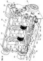
- FIG. 1 is a arranged in an ATM vault 10 with a total of four superposed exchangeable cassettes 12a to 12d shown.
- Each cassette 12a to 12d is associated with a separating and stacking module 14a to 14d, with the aid of which banknotes in the respective cassette 12a to 12d are removed and, alternatively, banknotes are fed to the respective cassette 12a to 12d with the aid of the separating and stacking module 14a to 14d can.
- the banknotes are stored in the cassettes 12a to 12d as a stack, the banknotes standing on its longitudinal side in the cassettes 12a to 12d are arranged.
- the banknotes can be fed to the separating and stacking modules 14a to 14d and removed from these separating and stacking modules 14a to 14d.
- the transport elements 16a to 16d which in particular comprise belts, rollers and / or switches, a transport path 18 is formed, via which banknotes are supplied from a transfer point 20, via which the banknotes are supplied to the safe 10 or are discharged from the safe 10 a selected separating and stacking module 14a to 14d are transported.
- a banknote taken from one of the cassettes 12a to 12d with the aid of the separating and stacking module 14a to 14d associated with this cassette can be fed to the transport elements 16a to 16d and along the transport path 18 via the transfer interface 20 to an operating unit of the ATM located above the vault 10 be transported with at least one input and output tray.
- banknotes to be deposited are stored in the input and output compartment as a bundle and separated in the upper part of the ATM, so that they are successively fed along the transport path 18 via the transfer interface 20 to the vault 10. Furthermore, the bills taken from the cassettes 12a to 12d are transported one by one along the transport path 18 via the transfer interface 20 from the vault 10 and then stacked into a stack by means of a known stacking device, which is designed, for example, as a stacker wheel. This bundle is then output through the input and output tray. Furthermore, the ATM has a suitable control unit and other elements, such as a card reader and optionally safety devices for authenticating an operator.
- FIG. 1 shown vault 10 with the cassettes 12a to 12d, the separating and stacking modules 14a to 14d and the transport elements 16a to 16d are also used in an automatic cash deposit.
- the banknotes are preferably transported along the transport path 18 at a transport speed of ⁇ 1.2 m per second, preferably ⁇ 1.4 m per second, and removed from the cassettes 12a to 12d at a corresponding speed or to these cassettes 12a to 12d fed to a corresponding speed.
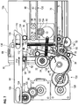
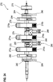
- FIG. 2 a separating and stacking module 30 according to a first embodiment of the invention is shown.
- the separating and stacking module 30 can after FIG. 2 as a separating and stacking module 14a to 14d FIG. 1 be used.
- Elements having the same structure and / or the same function are identified by the same reference numerals.
- the separating and stacking module 30 has as separating elements three juxtaposed take-off wheels 32, which are arranged resiliently mounted on a take-off wheel shaft 34 and are non-rotatably connected to this shaft 34. At the in FIG. 2 Side view shown only one of the take-off wheels 32 is visible.
- the Abzugsradwelle 34 is resiliently mounted at one end, so that it is horizontally displaceable at this shaft end and is pressed by the spring force to the front side of the cartridge 12a and thus against the end face of a arranged in the cassette 12a stack 36 of banknotes, if this Stack 36 is arranged in a singulation position.
- a first banknote 38 to be supplied in the direction of the arrow P0 is fed by means of drive wheels 44 arranged on a main drive shaft 42 into a supply area 46 in front of the stack 36 located in the cassette 12a.
- a guide member 48 is provided that the drive wheels 44 partially encloses and that the movement the bill 38 around the drive wheels 44 around.
- a pinch roller 50 is provided, by means of which the banknote 38 are pressed for transport to the drive wheels 44.
- two stripping rollers 52 are arranged on a shaft 53, which have a freewheel in the present embodiment, so that they rotate according to a rotational movement of the drive wheels 44 in the direction of the arrow P1 drawn without rotation of the shaft 53 accordingly.
- the wiping rollers 52 preferably have a peripheral surface made of rubber or other material with a relatively high coefficient of static friction, so that when two banknotes get into the gap between the drive wheel 44 and stripper roller 52, the wiping roller 52 facing Banknote is stripped from the drive wheel 44 facing bill and not further transported to the pressure roller 50. This can ensure that only one banknote is removed at the same time when banknotes are removed from the cassette 12a.
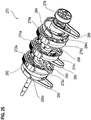
- the separating and stacking module 30 also has a plurality of impellers 54 arranged on a drive shaft 62, each having two vanes 58, 60 projecting tangentially from a hub 56 of the impeller 54.
- the wings 58, 60 are rotatably connected to the drive shaft 62, so that the impellers 54 by means of a drive unit via this shaft 62 in the direction of rotation of the arrow P2 shown are driven.
- the ends of the wings 58, 60 are curved counter to the direction of rotation, so that upon rotation in the direction of the arrow P2 the end face of the stack 36 with its curved outside contact.
- the stack 36 comprises a plurality of banknotes having a relatively small first height, one banknote of which forms the front side of the stack 36, and a plurality of banknotes of a larger second height, one banknote of which forms the rear side of the stack 36.
- the impeller 54 is in FIG. 2 in a stacking base position, in which a horizontally oriented wing 60 of the impeller 54 presses against the end face of the stack 36 and presses the banknotes of the stack 36 out of the feed region 46 into the cassette 12a.
- the banknote 38 is transported into the feed region 46.
- the take-off wheel 32 is additionally driven in the direction of the arrow P6, that is to say in the feed direction of the banknote 38.
- the impeller 54 is rotated via the drive shaft 62 so that the leading edge of the bill 38 does not contact the wing 60.
- the separating and stacking module 30 further comprises a total of four inclined deflectors 64, which are pressed in the present embodiment with its end facing the stack 36 by means of a prestressed spring 65 against the end face of the stack 36.
- FIG. 2 On the shaft 62, five further upper impellers 54 are arranged and non-rotatably connected thereto, so that the shaft 62 serves as a drive shaft for this total of six impellers 54.
- An in FIG. 2 visible lower impeller is designated by the reference numeral 66.
- FIG. 2 individual elements of the cassette 12a shown as such.
- B. a note retracting flap 68 the in FIG. 2 is shown in an open state and has been moved by means of separate from the cassette 12a arranged drive elements in this open position.
- springs which exert a force on the note retracting flap 68 in the direction of its closed position.
- the separating and stacking module 30 has a pressure device 45, which contacts a banknote 38 positioned in the feed region 46 in front of the front side of the stack 36 and presses this banknote 38 at least at the contact points against the front side of the stack 36.
- the pressing device 45 is designed to contact the banknote 38 in its lower half when it is positioned in front of the end face of the stack 36.
- the pressure device 45 may comprise at least one designed as a pressure pin anchor of a pull or thrust magnet or coupled to the anchor An horrit.
- cassette impellers 72 which are rotatably connected to the drive shaft 71 together with pulleys for deflecting belts 70 located at the bottom of the bill receiving area of the cassette 12a.
- a gear (not shown) is arranged, which is non-rotatably connected to this drive shaft 71 and via which the drive shaft 71 is driven by a separate from the cartridge 12a arranged drive unit, if another coupled to the drive unit gear with this Gear arranged on the drive shaft 71 is engaged.
- the lower impeller 66 After feeding the banknote 38 into the feed region 46, ie when its trailing edge is no longer in the area between the drive wheel 44 and the pressure roller 50, the lower impeller 66 is rotated so that at least one vane 74, 76, 78 of the lower impeller 66 presses the trailing edge and / or the lower portion of the banknote 38 against the end face of the stack 36. This pressing of the lower region by means of the lower impeller 66 takes place substantially simultaneously with the movement of the banknote 38 effected by the oblique deflector 64 towards the stack 36.
- the separating and stacking module 30 comprises a light barrier arrangement 39, which detects the leading edge of a fed banknote 38 in the area between the drive wheel 44, so that starting from the time of arrival of the leading edge of the fed banknote 38 and a preset delay time, the drive of the impeller 54 via the drive shaft 62 is started.
- the light barrier arrangement 39 comprises a prism arrangement for twice deflecting a light beam emitted by a light source, the light source and a light sensor for detecting the light beam emitted by the light source being arranged on the same side of the transport path for feeding and discharging a banknote 38.
- the prism arrangement is arranged on the opposite side of the transport path.
- the separating and stacking module 30 comprises a stripping element 75 to optionally banknotes 38 on Adhere to the surface of the drive wheel 44, to release from this and lead into the feed region 46.
- the stripping element 75 is preferably pressed by a spring force against a stop and thereby held in the position shown.
- FIG. 3 is that in FIG. 2 illustrated singulation and stacking module 30, wherein the feed elements 52, 54 and the transported into the feed area 46 banknote 38 are shown in a second feed position, which is different from the in FIG. 2 different stacking basic position.
- the banknote 38 is at the in FIG. 3 shown feed position opposite to in FIG. 2 shown position further transported into the feed area 46. Because of already related to FIG. 2 described control of the drive of the impeller 54, this has been driven via the drive shaft 62 in the direction of the arrow P2, so it now the in FIG. 2 has shown position. This ensures that a distance between the front edge of the banknote 38 and the wing 60 is maintained, so that the supplied banknote 38 does not contact the wing 60 and the feeding movement of the banknote 38 is not affected by contact with the wing 60.
- the lower impeller 66 is further rotated so that the wing 74 of the lower impeller 66 approaches the trailing edge of the fed bill 38 and subsequently presses the trailing edge and the lower portion of the fed bill 38 against the stack 36.
- the wings 74, 76, 78 are tangentially from a hub of the lower impeller 66, preferably at 0 °, 90 ° and 180 °.
- the wings 74, 76, 78 of the impeller 66 are made of an elastic material, preferably made of a rubber and / or plastic material and preferably curved in the direction indicated by the arrow P4 direction of rotation of the lower impeller.
- the vanes 74 to 78 press with a relatively large force against the lower region of the supplied banknote 38 during a rotational movement of the lower impeller 66 in the direction of the arrow P4 and then deform to between the front-side stack bottom edge of the stack 36 and the hub of the lower Impeller 66 to be pulled through.
- the wings 74 to 78 are so from the hub of the impeller 66 from that they need to be pivoted at a rotational movement of the arrow P4 only a relatively small angle to the hub to at least partially abut the peripheral surface of the hub.
- FIG. 4 is a further schematic representation of the separating and stacking module 30 after the FIGS. 2 and 3 illustrated, wherein the feed elements 54, 66 and the supplied banknote 38 are shown in a third feed position. In this third feeding position, the upper vane 54 is further rotated in the direction of the arrow P2.
- FIG. 5 is a schematic representation of the separating and stacking module 30 after the FIGS. 2 to 4 shown, wherein the feed elements 54, 66 and the supplied banknote 38 are shown in a fourth feed position.
- the upper impeller 54 has been further rotated in the direction of the arrow P2, so that the wing 58 is pivoted into the feed region 46 and subsequently into the in FIG. 2 shown staple basic position is further rotated, in which the front curved portion of the wing 58 presses against the supplied banknote 38 and pushes it together with other banknotes of the stack 36 in the banknote receiving area of the cassette 12a.
- the three wings 74 to 78 are guided past the trailing edge of the supplied banknote 38 until they are again in the banknote 38 FIG. 2 arranged stack base position are arranged. Further, the lower portion of the bill 38 is pressed by the pressing device 45 against the front side of the stack 58, whereby a flutter of the bill 38, which is particularly effected by the passing wings 74 to 78, is reduced.
- the note retracting flap 68 has a multiplicity of openings through which the upper impeller 54, the oblique deflector 64 and the take-off wheel 32 pass and, depending on the operating state of the separating and stacking module 30, contact a banknote 38.
- the further upper impellers 54 and the further oblique deflectors 64 further openings in the note retracting flap 68 are provided so that these, in the same manner as already for the feeding and separating elements 32, 54, 64 explained, the banknote 38 can contact through the note retracting flap 68 therethrough.
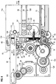
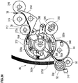
- FIG. 6 is a further schematic representation of the separating and stacking module 30 after the FIGS. 2 to 5 wherein the feeding elements and the separating elements and the banknote stack 36 arranged in the cassette 12a are shown in a separating position for withdrawing a banknote 38 from the banknote stack 36 present in the cassette 12a.
- the wings 58, 60 of the upper impeller 54 are connected via the drive shaft 62 in an in FIG. 6 shown stack basic position has been rotated and remain in this staple basic position during the entire separation process for removal and removal of a banknote 38 from the cassette 12a.
- the stack 36 With the aid of a driven by an electric motor 80 displacement carriage 82, the stack 36 is moved to a separating position to the take-off wheel 32, so that the Front side of the stack 36 and the end face of the stack 36 forming banknote 38 is pressed against the lateral surface of the Abzugsrades 32 and against the surface of parallel to Abzugsrad 32 arranged further take-off wheels 32.
- the oblique deflector 64 By moving the stack 36 toward the take-off wheel 32, the oblique deflector 64 is pivoted about the axis of rotation 63, as a result of which the spring 65 generating the pressing force of the oblique deflector 64 is pretensioned or further pre-stressed.
- a rotation of the take-off wheel 32 in the direction of arrow P7, opposite to the direction indicated by the arrow P6 rotational direction of the take-off wheel 32 in the FIGS. 2 to 5 is directed.
- the foremost banknote 38 of the stack 36 is pushed or transported downwards past the stripper rollers 52 into the area between drive wheels 44 and pressure roller 50.
- the surfaces of the drive wheels 44 and the take-off wheels 32 preferably have a relatively high coefficient of friction.
- the surfaces of the take-off wheels 32 and the drive wheels 44 are formed of rubber or other material having similar coefficients of friction.
- the surface of the Abzugsrades 32 is structured by transverse grooves. By means of these transverse grooves, a greater adhesion between the surface of the take-off wheel 32 and the banknote 38 to be moved downwards can be generated.
- the drive wheels 44 are driven in the direction of arrow P8.
- the lower impeller 66 is positioned in a separating basic position, that its wings 74 to 78 do not protrude into the transport path for removal and further transport of the banknote 38.
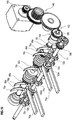
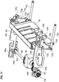
- the transfer carriage 82 has axles 84, 86 which each extend from the transfer carriage 82 to the side walls of the cassette 12a laterally delimiting the stack 36, guide wheels 92, 93 engaging in guide rails 88, 90 being provided at the ends of the axes.
- the guide rails 80, 90 are formed in or on the side walls.
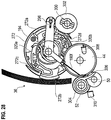
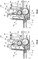
- FIG. 7 is an arrangement with the singulation and stacking module 30 after the FIGS. 2 to 6 with further elements of the cassette 12a for storing the banknotes and with a drive for actuating the note retracting flap 68, the note retracting flap 68 being shown in the illustration FIG. 7 is shown in an open position.
- a drive unit 96 shifts a pusher 98 via gear stages 100, 102, in the direction of the arrow P10.
- the gear stages 100, 102 each generate a reduction.
- the output gear of the gear stage 102 engages in a formed on the thrust element 98 rack 104 for moving the thrust element 98 a.
- the thrust element 98 also has elongated holes 106, 108, through the guide pins, not shown protrude, wherein the displacement region of the thrust element 98 is limited by these guide pins and the slots 106, 108.
- the pushing element 98 also has a bevel 110. In FIG. 7 the thrust element 98 is shown in a position in which no further displacement in the direction of the arrow P10 is possible by the already mentioned limitation of the displacement range.
- lever 114 With the help of the thrust element 98 has a pivotable about the axis of rotation 112 lever 114 has been pivoted. By pivoting the lever 114, the note retracting flap 68 has been moved away from the end face of the stack 36, whereby an already in connection with the FIGS. 2 to 5 explained supply and separation opening P5 is opened.
- a spring 116 is provided for retracting the note retracting flap 68, which exerts a restoring force on the note retracting flap 68.
- This restoring force is transmitted from the note retracting flap 68 at least partially to the lever arm 118.
- This restoring force of the second lever arm 120 is pressed in the present embodiment from below against the thrust element 98.
- the slope 110 of the thrust element 18 is formed as a wedge-shaped slope, whereby the thrust element 98 is also referred to as a wedge slide.
- FIG. 8 closing the note retracting door 68 will be explained in more detail.
- a drive shaft 122 driven via the motor 80, for displacing the displacement carriage 82 and a gearwheel 124, connected to the shaft 122 in a rotationally fixed manner at one end of the drive shaft 112, are shown.
- the Gear 124 engages a rack 120 formed on the lower guide rail 90 fixedly connected to the cassette 12a.
- the gear 124 for engaging a rack formed on the cassette 12a may be combined with one of the guide rollers 92, 94 or may replace it.
- a further sensor arrangement 126 in addition to the light barrier arrangement 39 already mentioned above.
- the sensor arrangement is provided for monitoring the feed region 46 and, in the present exemplary embodiment, is designed as a transverse light barrier. With the aid of the transverse light barrier 126, banknotes 38 can be detected when they are in the feed region 46.
- a drive unit 128 and a gear stage 130 for driving the drive shaft 42 is shown, on which the drive wheel 44 is arranged.
- the drive units 128, 96, 80 are embodied in the present exemplary embodiment as electric motors, preferably as stepper motors or as direct-current motors, although one part of the drive units may also be designed as stepping motors and another part as direct-current motors.
- FIG. 8 is the arrangement after FIG. 7 shown with a closed note retracting flap 68.
- the pushing element 98 is connected by means of the drive unit 96 and the gear stages 100, 102 has been moved in the direction of arrow P11.
- the lever 114 has been pivoted about the force introduced by the spring 116 in the note retracting flap 68, after a arranged at the end of the lever arm 120 rotatable guide roller 134 has been guided in the sliding movement in the direction of the arrow P11 on the slope 110 upwards.
- the lever arm 118 is pivoted counterclockwise about the rotation axis 112, so that the note retracting flap 68 is rotated about a rotation axis 136 and the removal and supply port P5 is at least closed so far that the removal of a bill of the stack 36 is not or only very cumbersome is.
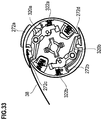
- FIG. 9 For example, a portion of the cassette 12a for storing banknotes after separating the cassette 12a from the separating and stacking module 30 is shown.
- the cassette 12a is for separating from the feeding and separating elements of the stacking and separating module 30 in the direction of the arrow P12 (see FIG FIG. 8 ) has been separated by pulling out the cassette 12a from an opening of the safe 10.
- the note retracting flap 68 has been previously pivoted by an active drive by means of the drive unit 96 by a corresponding movement of the thrust element 98 in its closed rest position. Until the note retracting door 68 is not located in the rest position, the cassette 12a is locked against being pulled out.
- the pivoting of the note retracting flap 68 is performed when the cassette 12a is moved in the direction of the arrow P12 automatically via the spring force of the spring 116, since even with a movement of the cassette 12a in the direction of arrow P12, the guide roller 134 of the lever arm 120 is guided along the slope 110 of the thrust element 98 so that the lever 114 is pivoted by the spring force of the spring 116 and the note retracting door 68 is closed.
- the cassette 12a has a plurality of mutually connected slats 138a to 138g for closing the end face 140 of the cassette 12a.
- the lamellae 138a to 138g are connected to the respective adjacent lamellae or formed in the connection region such that a relative pivoting of the lamellae 138a to 138g about the axes of rotation 142a to 142e in a limited angular range is possible, so that the laterally guided in guide rails 144 Lammellen 138a to 138g are guided along a predetermined by the guide rails cam track.
- the slats 138a to 138g are shifted to an area below the banknote receiving area of the cartridge 12a when the inserted cartridge 12a is in a working position.
- the feeding and separating elements can contact a banknote 38 arranged at the front side of the stack 38 through the openings in the note retraction flap 68.
- the slats 138a-138g cover both the substantially vertical face 140 of the cassette 12a and an area from the face 140 below the note-retracting shutter, so that the entire feed and removal area is completely covered by the slats 138a-238g. when the cassette 12a is removed from the vault 10.
- Moving the Lammelen 138a to 138g in the in FIG. 9 shown closed position and the displacement of the lamellae 138a to 138g in an open position is preferably via engagement elements when inserting and pulling out of the cassette 12a in the vault 10 or from the vault 10.
- When pushing in then takes place preferably an intervention of at least one in the vault 10th fixedly arranged engagement element in at least one engagement opening at least one lamella 138a to 138g.
- the lamellae 138a to 138g are opened like a roller shutter or a blind when the cassette 12a is pushed further into the safe 10, ie in a direction opposite to the arrow P12, so that the end face 140 of the cassette 12a as well an area on the underside of the cassette 12a is opened from the end face 140 of the cassette 12a.
- This lower area preferably extends to the front side of the banknote stack 38, so that in particular the wings 74 to 78 of the lower impeller 66 can contact the banknote stack 36 as described.
- the slats 138a to 138d are restored to the position shown in FIG FIG. 9 shifted shown in the closed position in which no access to the note retracting flap 68 and the present in the cassette 12a banknote stack 36 is possible.
- the slat 138g is at least partially covered by a bottom plate of the cassette 12a, so that the cassette 12a is moved by sliding the slats 138a until 138g is completely closed in the closed position.
- this closed position there are no openings through which notes or parts of banknotes could be taken.
- FIG. 10 3 there is shown a three-dimensional view of the drive elements for driving cassette vane wheels 72 arranged in the cassette 12a near the end face 140 and the shaft 53 with the lower vane wheels 66 thereon and the scraper rollers 52 arranged thereon.
- the drive shaft 71 is driven via a plurality of gear stages 148 to 154, on which a gear 158 two toothed pulleys 160a, 160b and a plurality of cassette impellers 72a to 72e rotatably arranged.
- about the pulleys 160a, 160b designed as a toothed belt bottom belt 70a, 70b are guided and deflected.
- the belts 70a, 70b contact the underside of the banknotes standing upright on the belts 70a, 70b, which are present in the stack 36 in the cartridge 12a, or at least part of these banknotes.
- the impeller 72e as the impeller 72 and the belt 70b as the belt 70 have been illustrated and designated.
- similar elements which are plural in a concrete arrangement are provided with the reference numerals themselves, when they are shown only once in the corresponding figure, and each with an additional continuous small letter when the element exists several times in a figure is.
- FIG. 11 a three-dimensional representation of the drive elements for driving the note retracting flap 68 is shown.
- the drive of the note retracting flap 68 is effected via an electric motor 96 which, via gear stages 100, 102 and a toothed rack 104a, 104b formed on the thrust elements 98a, 98b, displaces the thrust elements 98a, 98b in parallel.
- the rotary motion initiated by the motor 96 is transmitted via a shaft 166 and a gear 103 disposed at the other end of the shaft 166, which meshes with the rack 104a.
- the driving rotational movement is converted into a linear movement, by which the pushers 98a, 98b are displaced in parallel.
- the pusher element 98a has an opening 162 through which further elements of the singulation and stacking module 30 can be made.
- the thrust element 98b has, in addition to the slots 106b, 108b, a further opening 164, through which further elements of the singulation and stacking module 30 can be guided.
- the Lever arms 118a, 118b contact the note retracting flap 68 on opposite sides, so that when the sliding elements 98a, 98b are displaced in parallel, this note retracting flap 68 is simultaneously opened or closed via the ends of the lever arms 118a, 118b.
- FIG. 12 is a three-dimensional representation of a lower 55 and shown with transmission elements for driving this viagelradwelle 55.
- two stripping rollers 52a, 52b are arranged on the shaft 55.
- the lower impellers 66a and 66b are arranged on a shaft 55 over the shaft 55 freely rotatable sleeve 168a and rotatably connected to this sleeve 168a.
- a gear 170a is further rotatably connected, so that the sleeve 168a via the gear 170a can be driven independently of the shaft 55.
- a double gear 172 is freely rotatably mounted on the shaft.
- This double gear 172 is used together with other gears 174, 176 and together with a belt drive 178 to reduce the drive speeds of a drive unit 175.
- the rotational movement of the rotatably mounted on a drive shaft 180 gear 176 on the drive shaft 180 and from this drive shaft 180 via other gears 182, 184, 186 on the rotatably connected to the sleeves 168a, 168b, 168c connected gears 170a, 170b, 170c transmitted.
- a further gear 186 is arranged, which via a Freewheel is connected to the shaft 55, so that a rotational movement of the stripping rollers 52a, 52b in the direction of arrows P20 P22 is possible when the shaft 55 is not driven via the gear 186 in the direction of the arrows P20, P22.
- the stripper rollers 52a, 52b are also driven in the direction of rotation of the arrows P20, P22 via the shaft 55 and the gear 186.
- the gear 186 may be rotatably connected to the shaft 55, thereby eliminating the freewheel. Then, the scraper rollers 52a, 52b are to be driven by feeding a banknote 38 into the feeding section 46 by a driving unit via the gear 186 and the shaft 55 in the direction of the arrows P20, P22.
- FIG. 13 a three-dimensional representation of separating elements for removing a banknote 38 from the cassette 12a and for further transport of the withdrawn banknote 38 is shown.
- the shaft 34 is connected via a magnetic coupling 188 with a drive unit, not shown, wherein the connection to the drive unit can be produced or separated as required by the magnetic coupling 188.
- This separation option via the coupling 188 is particularly useful when the drive unit for driving the shaft 34 further elements of the singulation and stacking module 30 and / or further transport elements 16a to 16d drives and the take-off wheels 32a to 32c should not always perform a rotational movement when the other elements are driven._German the main drive shaft 42, the drive wheels 44a to 44n are arranged. Between the drive wheels 44d, 44e, 44f, 44g and between the drive wheels 44h, 44i, 44j, 44k, a retaining element 190a to 190f is arranged in each case.
- the retaining elements 190a to 190f are finger-like from a shaft 194, with which they are rotatably connected, from.
- the retaining elements 190a to 190f can be moved out with their end remote from the shaft 194 from the spaces between the drive wheels 44d to 44g and 44h to 44k, so that they from the Hüllmantel configuration to this Drive wheels 44b to 44k emerge and pressed against the surface of the stripper rollers 52a, 52b.
- the banknotes present between the wiping rollers 52a, 52b and the retaining members 190a to 190f are thus pressed by the retainer members 190a to 190f against the wiper rollers 52a, 52b for preventing a double trigger.
- the swivel assembly includes a drive magnet 192 as a drive unit.
- the drive shaft 34 is driven via the magnetic coupling 188 and arranged at one end of the shaft 34 gear 189.
- the opposite end of the shaft 34 is pressed by means of a pressure device 195 in the direction of the note stack 36.
- the pressure device 195 further comprises a pressure sensor, which at least one position of the detected in the pressing device 195 end of the drive roller 34 detected.
- the take-off wheels 32a to 32c Due to the resilient mounting of the take-off wheels 32a to 32c, which are preferably arranged on a common sleeve 196, wherein the sleeve 196 is resiliently mounted on the drive shaft 34, the take-off wheels 32a to 32c with a desired preset contact pressure aligned parallel to the end face of the stack 36 are pressed so that no skewed withdrawal of the notes 12a to be removed from the cassette 12a takes place.
- the take-off wheels 32a to 32c are rotatably mounted on the sleeve 196, wherein the sleeve 196 is rotatably connected to the drive shaft 134.
- the drive shaft 42 is driven via the arranged at one end of the drive shaft 42 gear 198 via drive elements of a arranged in the vault 10 central distribution module, the further transport elements 16a to 16d of the transport path 18 drives.
- This gear 198 is designed as a double gear and drives the drive side of the magnetic coupling 188 at. As a result, no separate drive for driving the drive wheels 44 and the take-off wheels 32 in the separating and stacking module 30 is required.
- a module separation takes place between the cassette 12a and the feeding and separating elements.
- a simple design inexpensive cassette 12a can be used, wherein the feeding and separating elements are arranged in the safe 10 or in the cash machine and remain on the removal of the cassette 12a in the safe 10 or in the cash machine.
- the cassette 12a can be used in a first ATM for depositing and withdrawing banknotes (cash recycling) and used in a new configuration of the same ATM or in the use of this cassette 12a in another ATM as pure payout cassette 12a.
- the cassette 12a it is advantageous to arrange the cassette 12a in such a way that the end face of a banknote stack 36 present in the cassette 12a is arranged perpendicularly, ie. H. that the stacking direction or the stacking depth is horizontal.
- the separating and stacking module 30 and the cassette 12a can also be arranged so that the stacking direction or the stacking depth is vertical, wherein the front side of the stack 36, deducted from the banknote 36 from the stack and the stack 36 more notes can be supplied is then arranged horizontally at the top of the stack 36.
- the upper two-bladed vanes 54 with rigid vanes 58, 60 are formed and arranged such that the enveloping circle of the vanes 58, 60 terminates upwardly at about the maximum allowable note height and in the horizontal Stacker basic position also supports a stack 36 formed from the smallest permissible banknotes 38 or pushes further into the cassette 12a.
- a wing turn occurs, ie, before feeding the banknote 38, the first wing 60 contacts the end face of the stack 36 and after feeding the banknote 38, the second wing 58 contacts the end face of the stack 36 a dynamic triggering of the wing envelope as a function of the banknote leading edge of the banknote 38 to be fed, detected by the light barrier arrangement 39, wherein the turnaround time is selected such that a banknote just fed 38 is displaced towards the stack 36 or beaten to the stack 36 with the outer curvature of the curved wing end becomes.
- the turnaround time is preferably set as a function of the size of the fed banknote 38, that is, it varies as a function of size.
- the slant deflectors 64 guide a fed banknote 38 away from the center of the wing 60 or 58 of the impeller 54 toward the front of the stack 36.
- the vanes 74, 76, 78 of the lower impeller are tangentially connected to a hub of the impeller 66, with the front Area of the wings 74, 76, 78 each having a curvature. The curvature is formed so that the blade tips in the direction of rotation of the impeller 54 when feeding a banknote 38 ahead of the remaining part of the wings 58, 60.
- the main drive shaft 42 with the drive wheels 44 is continuously driven by an electric motor for driving the transport elements of the transport path 18, wherein the drive shaft 34 with the take-off wheels 32 arranged thereon can be selectively coupled or decoupled via the magnetic coupling 188 with the drive of the drive wheels 44.
- the continuous drive of the drive wheels 44 and the optional drive of the take-off wheels 32 is effected by a central drive for the arranged in the safe 10 transport elements 16 a to 16 d, which has a large torque reserve, so that difficult to be separated bank notes, z. As adherent, freshly printed banknotes or notes with polymer film, isolated by means of the take-off wheels 32 and can be transported by means of the drive wheels 44.
- the take-off wheels 32 are driven by the switched magnetic coupling 188 until the bank note has reached the detection range of the light barrier arrangement 75 arranged in the region of the drive wheels 44.
- This has the advantage that the overall procedure for deduction and further transport of the banknote 38 in case of delays in the deduction or further transport, for example, as a result of adhering banknotes, not out of step, as may occur in rigidly mechanically coupled separating drives. Rather, the arrival of a sheet edge of the banknote to be removed 38, the removal is simply continued, so that the control for the removal of the banknote 38 in response to the event "arrival of the sheet edge of the withdrawn banknote 38 in the detection range of the light barrier arrangement" event-controlled.
- the already mentioned stack pressure is determined in particular by the stack thickness, the state and the properties of the bank notes arranged in the stack 36 and the position of the transfer carriage 82. Almost throughout the entire period in which the banknote 38 to be supplied is transported into the feed region 46, the stack 36 is pressed out of the feed region 46 with the aid of the upper impellers 54.
- a plurality of impellers 54 are arranged distributed on the horizontally arranged in the first embodiment of the invention drive shaft 62 over the maximum allowable note width.
- the drive shaft 62 is driven with the vaned wheels 54, preferably by means of a stepper motor, wherein the drive shaft 62 is rotated by 180 ° each time a banknote 38 is fed.
- the impellers 54 are driven such that the front edge of a fed banknote 38 projects into the feed region 46 Wings 58, 60 not contacted, but rather that a minimum distance between the front edge of the supplied banknote 38 and the wing 58, 60 by a suitable control of the stepping motor for driving the drive shaft 62 takes place.
- the wings 58, 60 have a relatively small width. In the present embodiment, they have a width of 6 mm.
- the impellers 54 in the stacking basic position in which the projecting into the feed area 46 wings 60 contact the sheet stack 36 below the smallest allowable note height. In the present embodiment, the smallest allowable note height is 58 mm.
- the pressure element 45 comprises in particular a thrust magnet whose armature is moved upon activation of the thrust magnet such that one end of the armature or a further element connected to one end of the armature presses against the pressure element 45 facing front or back of the banknote 38 and the Banknote 38 shifts at least in the contact area towards the front side of the already existing stack 36 and presses against this end face of the existing stack 36.
- the circulation time of the upper impeller 54 in a rotation through 180 ° is preferably preset so that the supplied banknote 38 is pushed by the second wing 58 to the front side of the stack 36 and pressed against this, as soon as the supplied banknote 38, the contact area between the drive wheel 44th and the pinch roller 50 has left.
- the oblique deflectors 64 cause relatively large banknotes, which are arranged as stacks 36 in the cassette 12a, not to bend over the wing 60 pressing against the end face of the stack 36 in the stack base position and into the area above the wing 60 in the stacking basic position protrude.
- the banknote or banknotes of the stack 36 arranged at the front side could be pulled upward by the wing 60 during a rotary movement of the impeller 54.
- the lower impeller 66 is preferably rotated when supplying a banknote 38 together with the drive wheels 44, wherein the lower impellers 66, as already described, independently of the counter shaft 55 are driven or rotatable.
- the flexible vanes 74 to 78 of the lower vanes 66 are elastically deformed and wound onto the hub of the respective impeller 66 so that a helical arrangement of the wound vanes 74 to 78 takes place.
- the drive of the lower impellers 66 also takes place via a separate stepping motor which drives the shaft 55 with the scraper rollers 52a, 52b arranged thereon via a freewheel, so that the scraper rollers 52a, 52b are also driven in the feed direction of the banknote 38 when a banknote 38 is fed thereby at least not obstructing the feeding of the banknote 38.
- the lower impellers 66 each have three wings 74 to 78, the bases of which are not uniformly distributed over the circumference, and leave a gap of 180 ° in the present embodiment.
- the lower impeller 66 For separating, ie for discharging, a banknote 38 from the cassette 12a, the lower impeller 66 is then aligned so that no wing 74 to 78 projects into the transport path for the removal of the withdrawn banknote 38. This position of the wings 74 to 78 of the lower impeller 66 are in FIG. 6 shown.
- the wings 74 to 78 are not center-centric arranged as explained at the hub of the lower impeller 66 but are laterally tangential. Thereby, the wings 74 to 78 can perform the described elastic deformation at a relatively low stress of the material.
- the foot zone associated with the hub of the impeller 66 will engage each of the wings 74-78 upon application the wings 74 to 78 to the hub at a rotational movement of the impeller 66 is not as much angled, as in a center-centric connection of the wings 74 to 78 to the hub.
- the note retracting door 68 is in its in FIG. 8 illustrated rest position preferably locked by means of locking elements on the cassette housing to ensure during transport of the cassette 12a that the note retracting flap 68 remains in the rest position.
- the movement of the note retracting shutter 68 is controlled via scenes provided in or on the outer walls of the cassette 12a.
- scenes provided in or on the outer walls of the cassette 12a.
- the note retracting flap 68 guide elements in engagement with the scenes, wherein preferably these guide elements are locked by means of the locking elements.
- the note retracting flap 68 must remain in the locked state in this rest position as long as the locking elements are engaged with the guide elements.
- the transfer carriage 82 After the transfer carriage 82 with a preset maximum pressure has pressed the banknote stack 36 present in the cassette 12a against the take-off wheels 32, the direction of movement of the transfer carriage 82 is reversed and a preset return path is covered. Due to different grades of grades, the required stacking space is different, in particular in the stack of notes 36 having a relatively large number of banknotes, so that a different pressure force from the notes to the feeding and separating elements of the separating and stacking module 30 occurs at a constant withdrawal path of the sliding carriage 82. In a first step, the transfer carriage 82 is moved away from the singulation and stacking module 30 by a first path.
- an indirect stack pressure determination is carried out, wherein the upper impeller 54 is to be rotated from the separation basic position in the stack basic position.
- Parallel to this rotational movement of the Upper impeller 54 of the transfer carriage 82 is further moved away from the singulation and stacking module 30, wherein at the same time the bottom belts 70 are driven so that they move the standing on the belt 70 notes from the separating and stacking module 30. This is continued until the wings 58, 60 of the upper impeller 54 have reached the stack base position or until the sensor arrangement 126 no longer detects a banknote in the detection area.
- the drive of the upper impeller 54 by means of the stepping motor is carried out at a reduced stepping motor current and with respect to the normal drive frequency reduced frequency.
- the allowable touch pressure can thus be determined by the moment of the stepper motor.
- stepper motors are in principle unsuitable for torque control, since a stepping motor skips over steps when a limit torque is exceeded, the torque falls to zero when steps are skipped. The torque is only rebuilt after four more steps.
- a freewheel is arranged on the drive shaft 62.
- a pulsating drive signal is used to drive the stepper motor, which increases with each pulse up to the value valid for the selected low frequency.
- a DC-DC motor or brushless DC motor may be used instead of the stepping motor.
- DLBC brushless DC motor
- Such motors are better suited for adjusting the stacking pressure, and thus better for positioning the transfer carriage 82, due to available torque controls.
- a position detection and control to detect the angular position of the drive shaft 62 and the upper impeller 54 is required. Such a positioning control is relatively expensive.
- a positioning control takes place in the lower region of the bank notes arranged as a stack 36.
- a sensor arrangement 126 designed as a transverse light barrier is provided, which is arranged at the boundary of the maximum required feed area 46 in the so-called stack foot zone and thus monitors the area in front of the end face of the stack 36.
- the feeding of banknotes 38 then takes place with continuously rotating drive wheels 44 and continuously rotating lower impellers 66.
- the take-off wheels 32 are rotated over the magnetic coupling 188 at least temporarily, in particular in order to prevent entanglement of the leading edge of the supplied banknote 38 on the lateral surface of the take-off wheels 32.
- banknotes 38 For each transaction, up to 200 banknotes 38 may be supplied to the cassette 12a.
- the transfer carriage 82 For each fed banknote 38, the transfer carriage 82 is moved in synchronism with the bottom straps 70 by a preset return path away from the singulation and stacking module 30, i. H. moved back in the cassette 12a. If this default retraction path is insufficient, after feeding a banknote 38 it will at least partially remain in the detection range of the monitoring light barrier arrangement 126 and be detected by it, as this banknote 38 could not be pushed sufficiently far into the spike node receiving area.
- the preset withdrawal path is in particular not sufficient if used banknotes 38 have a greater resulting note thickness in the stack due to their deformation.
- the preset return path of the transfer carriage 82 is thus not sufficient to provide the bills supplied sufficient stacking space available. If the light barrier arrangement 126 detects a banknote in the detection area, the transfer carriage 82 is displaced away from the singulation and stacking module 30 by an additional return path.
- a Swiss-Field is provided because at too large a preset return movement of the transfer carriage 82 or uneven banknotes a relative poor filling level in the cassette 12a would be achieved.
- a Swiss-Schiff is provided if more than 150 banknotes, a maximum of 200 banknotes have been supplied.
- the procedure corresponds to the already described process for adjusting the stacking pressure after feeding the cassette 12a or before positioning the upper impeller 54 in the stack basic position.
- the air gaps created by a preset generous increment in the retraction of the shuttle carriage 82 are at least partially removed from the stack 36 by compressing the entire stack 36.
- the impeller 54 After singulation in which the unbent portions of the vanes 58, 60 of the upper impeller 54 are oriented substantially vertically, the impeller 54 is again rotated to a stacking base position in which the unbent portions of the vanes 58, 60 of the upper impeller 54 are essentially level.
- this stacking basic position all the bills of the stack 36 are arranged in the cassette 12a, so that the cassette 12a can be removed from the safe 10 as soon as the note return flap 68 has been swung inwards.
- the pivoting of the note retracting flap 68 in the rest position is carried out as already mentioned with the aid of FIG. 11 If the cassette 12a can be removed without further preparation, in particular in the low-power state of the ATM, the note retracting flap 68 must always be pivoted to the rest position, if currently no supply and no removal operation is performed.
- FIG. 14 is a three-dimensional representation of a singulation and stacking module 200 according to a second embodiment of the invention with three juxtaposed conveyor belts 202 to 206 each shown with transport tabs 202a to 206a.
- the transport tabs 202a to 206a banknotes are fed to the cassette 12b.
- the separating and stacking module 200 has two take-off wheels 208, 210 with the aid of which the bank notes present as a stack 36 in the cassette 12b are removed individually from the cassette 12b, ie, the bank notes are separated.
- the endless conveyor belts 202 to 206 are guided over upper deflecting rollers 212 to 216, which have lateral guides in the manner of a pulley for laterally guiding the endless conveyor belts 202 to 206.
- the deflection rollers 212 to 216 are non-rotatably connected to a drive shaft 218, which is driven by an electric motor 220.
- the drive of the shaft 218 via a belt drive 222.
- each conveyor belt 202 to 206 each have a lower guide roller 224 to 228 provided which are freely rotatably mounted on a drive shaft 230 for driving the take-off wheels 208, 210 and via suitable axial limiting elements in their axial position on the drive shaft 230 are held.
- the endless conveyor belts 202 to 206 and the transport straps 202a to 206a have a perforation along the circumference of the endless conveyor belt 202 to 206 with a plurality of holes arranged at equal distances from one another.
- the upper pulleys 212 to 216 have to the perforation of the conveyor belts 202 to 206 complementary protruding spines, which engage in the perforation, so that both a further lateral guidance and a slip-free drive of the conveyor belts 202 to 206 takes place.
- the drive of the conveyor belts 202 to 206 takes place in the direction of the arrow P50.
- engagement elements which are each preferably designed as a single-wing impeller 232 to 240, a gap between the circulating conveyor belt 202 to 206 and the respective downwardly opened transport tabs 202a to 206a can be generated or increased, so that the conveyor belts 202 to 206 a Zunaturalgroundwolf respectively.
- the feeding of a banknote 38 via the drive wheels 44 By opening the transport tabs 202a to 206a by means of the wings 232 to 240, a feed region between the circulating conveyor belt 202 to 206 and generated on the outside of the transport tabs 202a to 206a adjacent banknote stack 36. In this feed area, a banknote 38 to be supplied is transported. As a result, in each case an area of this banknote 38 is introduced into the transport straps 202a to 206a or guided between the transport straps 202a to 206a and the conveyor belts 202 to 206.
- the conveyer belts 202 to 206 in the direction of the arrow P50 substantially coincide with the driven the same rotational speed, such as the speed at which the supplied banknote 38 has been conveyed by means of the drive wheels 44 in the transport tabs 202a to 206a.
- stripping elements are provided which prevent the banknote arranged with regions in the transport straps 202a to 206a from further circulation with the conveyor belts 202 to 206 and thereby pull the transport straps 202a to 206a in a further drive of the conveyor belts 202 to 206.
- stripping elements are arranged such that the banknote 38 drawn from the transport straps 202a to 206a is positioned opposite the end face of the stack 36 already in the cassette 12a. Furthermore, pressure elements 242 to 248 are provided, which protrude via a pull magnet 247 from the regions between the transport belts 202 to 206 and which press the end face of the stack 36 already present in the cassette 12a opposite the banknote 38 against the front side of the stack 36. so that the supplied banknote 38 forms the new front side of the stack 36.
- FIG. 14 Furthermore, individual elements of the cassette 12b, such as the transport belts 70a, 70b and transport rollers 249a to 249d are shown. Also, the stripping elements 52a, 52b and the already in connection with FIG. 13 and the first embodiment of the invention illustrated retaining elements 190a to 190f shown in its rest position according to the first embodiment and the second embodiment of the invention.
- This in FIG. 14 Separation and stacking module 200 shown further comprises a magnetic coupling 242, via which the main drive shaft 42 with the drive wheels 44 is selectively driven.
- FIG. 15 is a simplified side view of the singulation and stacking module 200 after FIG. 14 shown, wherein the feeding and separating elements are shown in a first position for feeding a banknote 38.
- a lower impeller 232 engages the transport tab 202a after the transport belt 202 has been moved against the direction of arrow P50 in a Zuzhougroundwolf.
- the impeller 232 has two protruding rigid wings. By the engagement of a wing of the impeller 232 in the transport tab 202a, this is opened further, so that a fed banknote 38 is guided into the area between the endless circulating conveyor belt 202 and provided on the outer peripheral surface transport tab 202a.
- the singulation and stacking module 200 comprises a stepping motor 250 as a drive unit, which drives the drive shaft 53 for driving the impellers 232 via a belt drive 251 and the magnetic coupling 242.
- the cartridge 12b shown in connection with the second embodiment has no vanes disposed in the cartridge 12a, but the already mentioned transport rollers 249a to 249d having a profiled peripheral surface.
- the profile of the transport rollers 249a to 249d has transverse ribs through which creates a positive connection with the banknotes in contact with the wheels 249a to 249d with their lower edge becomes. As a result, the banknotes can be transported safely in the direction of the stack 36 or into the cassette 12b.
- the pressure element 242 is in FIG. 15 simplified illustrated as a swivel lever. Both the pivoting levers 242 to 248 serving as pressing elements and the profiled transporting rollers 249a to 249d can also be used in the first embodiment of the invention, in the same way the impellers of the first embodiment arranged in the cassette 12a and those in FIG FIG. 8 shown and described in this context pressure element can be used in the second embodiment of the invention.
- FIG. 16 is the side view of the singulation and stacking module 200 after FIG. 15 illustrated, wherein the feeding and separating elements are shown in a second position when feeding a banknote 38.
- the banknote 38 arranged in some areas in the transport straps 202a to 206a has been pulled out of these transport straps 202a to 206a, the banknote 38 and the entire stack 36 being pushed away from the conveyor belt 202 with the aid of the pressure elements 242 to 248 have been.
- the endless conveyor belt 202 is driven against the direction of the arrow P50, in parallel with the lower impeller 232 is further driven and rotated. In this case, one wing of the impeller 232 presses the lower area of the banknote 38 against the banknote stack 36.
- FIG. 17 is the side view of the separating and stacking module 200 after the FIGS. 15 and 16 shown, wherein the feeding and separating elements are shown in a third position when feeding the banknote 38. In this position it can be seen that a wing of the lower impeller 232 at the same time surrounds the trailing edge of the fed banknote 38 and also engages in the transport tab 202a.
- FIG. 18 is the side view of the singulation and stacking module after the FIGS. 15 to 17 2, wherein the feeding and separating elements are shown in a fourth position, in which the lower area of the supplied banknote 38 has been displaced towards the stack by means of the lower impeller 232 and at the same time the transporting tab 202a has been opened for supplying a further banknote.
- FIG. 19 is a simplified side view of the singulation and stacking module 200 after the FIGS. 14 to 18 alternative singulation and stacking module 252 shown for stacking and separating banknotes.
- the feeding and separating elements are shown in a first position when feeding a banknote.
- the singulation and stacking module 252 differs from the singulation and stacking module 200 according to the FIGS. 14 to 18 by the formation of the lower impeller 232, wherein the two wings of the lower impeller 232 at the separating and stacking modules 200, 252 each have an angular distance of 141 ° and 219 °.
- the impeller 232 is rotated such that when feeding a banknote 38, the wings are arranged such that they face the banknote 38 with their smaller angular spacing of 141 °.
- the lower impeller 232 is rotated in such a way that the blades of the impeller 232 with their large angular spacing of 219 ° face the supplied banknote 38.
- the transport tab 202a in the same manner as in connection with FIG. 15 opened for a banknote 38 to be supplied.
- FIG. 20 is the side view of the separating and stacking module 252 after FIG. 19 shown, wherein the feeding and separating elements are shown in a second position when feeding the banknote 38.
- the lower impeller is simultaneously rotated when driving the conveyor belt 202 against the direction P50, so that the in FIG. 16 Down arranged wings of the impeller 232 surrounds the trailing edge of the fed bill 38 and at the same time engages in the transport tab 202 a, as shown in FIG. 21 is shown.
- the wing pushes the lower portion of the fed banknote 38 towards the stack 36 and simultaneously opens the transport tab 202a, as shown in FIG FIG. 22 is shown.
- FIG. 23 is one in the vault 10 after FIG. 1 arranged banknote cassette 12b with a separating and stacking module 200 according to the second embodiment of the invention shown for feeding and removing banknotes. Furthermore, a section of the transport path 18 and a transport roller pair 260 with a drive roller 262 and a pressure roller 264 are shown. With the help of the transport roller pair 260, a transport path for banknotes between the separating and stacking module 200 and the transport path 18 is formed. The transport elements of the transport path 18 and arranged in this transport path switches are in FIG. 23 not shown.
- the separating and stacking module 200 is already in the stacking basic position in the illustration according to FIG.
- FIG. 23 in which a banknote to be fed to the cassette 12b can be transported into the gap between the opened transporting lug 202a and the endless conveyor belt 202 by means of the drive wheel 44.
- the transfer carriage 82 disposed in the cassette 12b is in FIG FIG. 23 not shown.
- the conveyor belts 202 to 206 with the transport straps 202a to 206a are also referred to as dandruff belts, since the transport straps 202a to 206a are in the form of scales on the respective conveyor belt 202 to 206.
- both the endless conveyor belts 202 to 206 and the transport tabs 202a to 206a are made of a polyester film having a uniform thickness in the range of 0.1 to 0.75 mm, preferably in the range of 0.2 to 0.35 mm. A strength of 0.25 has proved to be advantageous.
- the singulation and stacking module 200 according to the second embodiment of the invention is also particularly suitable for a vertical cassette arrangement, ie in an arrangement of the cassette such that the end face of the stack 36 is arranged in a horizontal plane, preferably at the top of the stack.
- a particular advantage of the separating and stacking module 200, 252 with the conveyor belts 202 to 206 is that a banknote 38 to be supplied is protected in the transport straps 202a to 206a when it is transported in front of the end face of the stack 36.
- the banknote 38 is covered in the front note section by the relatively wide transport tabs 202a to 206a and has no direct contact with the end face of the stack 36 in the area of the transport tabs 202a to 206a.
- the fed banknote 38 can not get caught in projecting areas of used banknotes.
- lower demands are placed on the rigidity of the banknotes to be supplied against buckling.
- the endless conveyor belt 202 with the at least one transporting lug 202a can be produced from two stamped foils which are welded to the endless conveyor belt 202 with transporting lug 202a at at least two connecting points, preferably by a respective welded connection.
- a welding method an ultrasonic welding method is particularly suitable.
- FIG. 24 1 is a plan view of a stacking and separating wheel shaft 270 of a separating and stacking module of a third embodiment of the invention with a total of three stacking and separating wheels 272 to 276 arranged on this shaft.
- the Stapelradwelle 270 is driven by an electric motor, wherein the drive of the shaft 270 via a non-rotatably connected to the shaft 270, the toothed belt pulley 278 takes place.
- toothed belt pulleys 280 to 284 are non-rotatably connected to the stacking and separating wheel shaft 270, by means of which toothed belts 286 to 290 can drive freely rotatably mounted cam disks on a shaft arranged parallel to the stacking and separating shaft 270.
- the separating and stacking wheels 272 to 2776 each have two pull-out elements 272a, 272b, 274a, 274b, 276a, 276b which can be moved out of the peripheral surface of the separating and stacking wheels 272 to 276.
- the outsides of these trigger elements 272a to 276b are each profiled by transverse grooves and have a relatively high coefficient of friction, so that banknotes already at a relatively low pressure force with the help of the trigger elements 272a to 276b can be moved or deducted.
- at least the surface of the trigger members 272a to 276b is made of a rubber material.
- the stacking and separating wheel shaft 270 has control levers 296, 298, the end of which is remote from the stacking and separating wheel shaft 270 for controlling the movement of the retaining or pressing elements 190_.
- clamping elements arranged via the control levers 296, 298 in the stacking and separating wheels 272 to 276 can be controlled via a cam disc arranged on the already mentioned parallel shaft and / or via cam disks arranged in the stacking and separating wheels.
- the separating and stacking wheels 272 to 270 each have two stacking chambers, wherein a transmission ratio of 1 to 2 is provided, so that the cams have twice the number of revolutions, as the stacking and separating wheel shaft 270th
- FIG. 25 shows a perspective view of the separating and Stapelradwelle 270 after FIG. 24 ,
- each a chamber 272 c to 276 c for receiving a portion of a supplied bill of the separating and stacking wheels 272 to 276 and the Stacking wheels 292 and 294 shown.
- the visible chamber of the separating and stacking wheel 272 is designated by the reference numeral 272c
- the visible chamber of the separating and stacking wheel 274 is denoted by the reference numeral 274c
- the chamber of the separating and stacking wheel 276 is denoted by the reference numeral 274c.
- the visible chamber of the stacking wheel 292 is designated by the reference numeral 292c and the visible chamber of the stacking wheel 294 is designated by the reference numeral 294c.
- FIG. 26 is a side view of the stacking and separating wheel shaft 270 after the Figures 24 and 25 shown, in which also the second chamber 292d of the stacking wheel 292 is visible.
- FIG. 27 shows the side view of the separating and stacking wheel 272 with the chambers 272c and 272d for receiving banknotes. Furthermore, the axis of rotation 300 of the cam 302 parallel to the separating and stacking wheel shaft 270 is shown.
- the cam 302 is scanned by the lever 296, wherein depending on the course of the cam 302 via the lever 296 at least one of the two trigger elements 272a, 272b can be moved out of the peripheral surface of the separating and stacking wheel 270 to the in the cassette 12c at a Front end of the stack 36 arranged banknote to contact.
- FIG. 27 is a starting position for separating (separation basic position) of existing in the cassette 12c
- Banknotes arranged in a stack 36 are shown.
- An impeller 304 having a blade 306 is rotated in a singulation mode so that the blade 306 does not protrude into the transport path for transporting the bank notes pushed down from the front of the stack 36 by means of the withdrawal members 272a, 272b.
- the banknote arranged one end face of the stack 36 is pushed downwards in a transport gap between the drive wheel 44 and the pressure roller 50.
- FIG. 27 is a starting position for separating (separation basic position) of existing in the cassette 12c
- FIG. 27 is a starting position for separating (separation basic position) of existing in the cassette 12c
- An impeller 304 having a blade 306 is rotated in a singulation mode so that the blade 306 does not protrude into the transport path for transporting the bank notes pushed down from the front of the stack 36 by means
- the arrangement further comprises a sensor arrangement for detecting the front edge of a banknote 38 to be paid off.
- the sensor arrangement can detect the trailing edge of the transported banknote 38.
- the sensor arrangement comprises, in particular, a light source 308 and a receiver 310 which, together with an evaluation unit, not shown, form a light barrier sensor arrangement.
- FIG. 28 is the arrangement after FIG. 27 shown with the outwardly pivoted trigger element 272a, wherein the trigger element 272a contacted in the moved-out state, the surface of the arranged on the front side of the stack 36 banknote 38 and in a further rotational movement of the separating and stacking wheel 272, the banknote 38 down into the transport gap between the Scraper element 52 and the drive wheel 44 and between the pinch roller 50 and the drive wheel 44 pushes.
- the cam plate 304 can also be driven via an electric motor, preferably a stepper motor, possibly together with further cam discs.
- FIG. 29 is the arrangement after the Figures 27 and 28 shown, wherein the feeding and separating elements are shown in a position in which the arranged on the end face of the stack 36 banknote 38 has already been pushed into the transport gap between the drive wheel 44 and the pressure roller 50.
- the banknote 38 interrupts the light beam between the light source 308 and the receiver 310, so that the light barrier arrangement detects the removed banknote 38.
- FIG. 30 is the arrangement after the FIGS. 24 to 29 , wherein the feeding and separating elements are shown in an operating mode for feeding banknotes into the cassette 12c.
- the impeller 304 with the wing 306 is rotated so that the banknotes of the Stack 36 and other fed banknotes 38 can not get into the area between the drive wheel 44 and stripping 52 and drive wheel 44 and pinch roller 50.
- a banknote 38 to be supplied is fed to the assembly from the transport path 18 via transport elements 312, 314, 316 and a diverter 318, the diverter 318 continuing to serve as a guide element.
- the supplied banknote 38 is transported into the chamber 272c with sections of its front area.
- the separating and stacking wheel 272 is in FIG. 30 in a start position for feeding banknotes into the cassette 12c.
- FIG. 31 is the arrangement after the FIGS. 27 to 30 shown, wherein the feeding and separating elements are shown in a second feed position.
- An unillustrated clamping element controlled by a further cam and a further lever 320a presses the banknote 38 in the chamber 272c from the inside against the outside of the chamber so that the banknote 38 is clamped in the chamber 272c.
- the process is controlled so that a rotation of the separating and stacking wheel 272 is started at the latest when the front edge of the fed banknote 38 has reached the chamber bottom or the end face of the chamber 272c, which forms a stop for the banknote 38 in the transport direction.
- the banknote 38 is clamped in the chamber 272c under the control of the cam plate, controlled by the lever 320a.
- the lever 320a is pressed against the spring force of a spring 322a against the outside of the chamber 272c.
- FIG. 32 is the arrangement after the FIGS. 27 to 31 shown, wherein the feeding and separating elements are shown in a third feed position, in which the separating and stacking wheel 272 relative to the in FIG. 31 shown second feed position is rotated further.
- This supply position of the clamped in the chamber 272c portion of the banknote 38 is still disposed in the chamber 272c.
- the clamping lever 322a is released via the cam, so that, although the area of the banknote 238 is still in the chamber 272c, it is no longer clamped.
- the rear portion of the banknote 38 is no longer in engagement with the transport elements 312 to 318, whereby the banknote 38 is lifted due to their rigidity from the lateral surface of the separating and stacking wheel 272 and thereby upright to the front side of the stack 36 back.
- the front edge of the supplied banknote 38 abuts against a plurality of stripping elements 324 arranged between the drive wheels 44, by means of which the movement of the banknote 38 is stopped.
- the separating and stacking wheel 272 is further rotated, so that the front region of the banknote 38 is no longer arranged in the chamber 272c during a corresponding further rotation of the separating and stacking wheel 272.
- the supplied banknote 38 is no longer in engagement with the separating and stacking wheel 272. Due to the rigidity of the supplied banknote 38, this aligns so that they are located immediately in front of the front side of the already in the cassette 12c Stack 36 is arranged and forms the new front side of the stack.
- FIG. 33 is a side view of the stacking and separating wheel 272 according to the third embodiment of the invention without inner cam shown.
- the cam not shown controls the movement of the clamping lever 320a, 320b, wherein the springs 322a, 322b press the lever ends against the cam.
- FIG. 34 is the stacking and separating wheel 272 after FIG. 33 in a further side view and in FIG. 35 shown in a perspective view.
- FIG. 36 shows a further side view of the stacking and separating wheel 272, wherein the in FIG. 33 shown side opposite the stacking and separating wheel 272 is shown without a second cam.
- FIG. 37 Figure 11 is a side view of the cassette 12c, together with a note retracting door 326 similar to the note retracting door 68, which has opposite the note retracting flap 68 to the stacking and separating wheels 272 to 278 and the separating wheels adapted cutouts. Furthermore, further transport elements for providing a transport path 18 are shown. In contrast to the described first and second embodiments of the invention are for the singulation and stacking module according to the third embodiment of the invention, two switches in the transport path 18 to be arranged, since the separating and stacking module to be supplied banknotes 38 the stacking and separating wheels 272 to 276 in supplied to the upper area and withdrawn banknote are discharged from the stacking and separating wheels 272 to 276 in the lower area.
- the note retracting door 326 and the banknote stack 36 are in FIG. 37 in its stacking and separating position and in a rest position, wherein the note return flap in the rest position by the reference numeral 326 'and the banknote stack by the reference numeral 36' denotes.
- FIG 38 is a side view of a separating and stacking module 350 shown according to a fourth embodiment, the alternative to the separating and stacking modules 30, 200, 252, 270 of the first three embodiments of the invention as separating and stacking module 14a to 14d FIG. 1 can be used.
- the separating and stacking module 350 is likewise engaged with the cassette 12a, as in connection with the first embodiment of the invention according to FIGS FIGS. 2 to 13 explained.
- the function and the structure are right the impellers 54, the note retracting shutter 68, the drive wheel 44, the Abstreifrades 52 with the first embodiment of the invention match.
- a lower impeller 232 according to the second embodiment of the invention according to the FIGS. 15 to 23 intended.
- a pressing device 352 is provided instead of the pressing device 45.
- the pressure device 352 comprises a traction magnet drive 354 which is coupled to a pressure ram 358 via a lever 356.
- the movement of the traction magnet drive 354 is deflected about a stationary axis of rotation 360.
- the movement of the plunger 358 is preferably limited or guided by further guide elements, not shown.
- the axis of rotation 360 is preferably formed by a housing frame protruding from a housing frame 362 arranged laterally of the separating and stacking module 350, which protrudes through a complementary opening provided in the lever 356 and thereby forms a deflection axis or axis of rotation 360.
- the banknote 38 is transported into the feed region 46, wherein the impeller 54 is already moved out of its stacking basic position in order to provide the banknote 38 with sufficient space also upwards and not to obstruct the movement of the banknote 38 when it is fed into the supply region 46 in particular, not to form a height stop.
- the upper impeller 54 has been further rotated.
- the lower impeller 232 has been rotated.
- the traction magnet drive 354 has been activated so that the pressure ram 358 contacts the supplied banknote 38 in its lower half and presses it in the direction of the end face of the stack 36.
- FIG. 40 For example, another subsequent feed position is shown in feeding the bill 38 into the cassette 12a.
- the lower impeller 232 and the upper impeller 54 have been further rotated, whereby the second wing 58 more contacted with the outside of the curved portion of the wing 58, the fed banknote 38 in its upper half and the banknote 38 by the further movement of the impeller 54th moved further in the stack base position in the direction of the stack 36 and presses against the end face of the stack 36.
- the lower impeller 232 is further rotated and contacts the supplied banknote 38 in its lower half, preferably at its lower edge, and presses the lower portion of the supplied banknote 38 against the front of the stack 36 already in the cassette 12a FIG.
- FIG. 41 is the singulation and stacking module 350 after the Figures 38 to 40 shown, wherein the separating and stacking elements are shown in a singulating position.
- the upper impeller 54 has been rotated to the stack base already described in connection with the first embodiment.
- the stack 36 located in the cassette 12a has been moved towards the take-off wheel 32, so that the front side of the banknote 38 forming the end face of the stack 36 is pressed against the lateral surface of the take-off wheel 32.
- the banknote 38 is pushed down into the gap between the drive wheel 44 and the stripping roller 52 and between the drive wheel 44 and the pressure roller 50.
- the note retracting flap 68 is in the in the FIGS. 38 to 41 shown in an open position and can be actuated in the same manner as in connection with the first two embodiments in conjunction with the FIGS. 2 to 37 described.
Abstract
Die Erfindung betrifft eine Einzelblatthandhabungsvorrichtung (14a bis 14d, 30, 200, 252, 270, 350) zur Eingabe und zur Ausgabe von rechteckigen Einzelblättern (38) in einen bzw. aus einem Behälter (12a bis 12d). Diese rechteckigen Einzelblätter können insbesondere Banknoten (38) sein. Die Einzelblatthandhabungsvorrichtung (14a bis 14d, 30, 200, 252, 270, 350) hat eine Zuführeinrichtung, die Zuführelemente zum blattweisen Zuführen von Einzelblättern (38) und zur Ablage dieser Einzelblätter (38) in einem Stapel (36) aus Einzelblättern im Behälter (12a bis 12d) umfasst. Ferner hat die Einzelblatthandhabungsvorrichtung eine Vereinzelungseinrichtung, die Vereinzelungselemente zum blattweisen Entnehmen von Einzelblättern (38) des Stapels (36) aus dem Behälter (12a bis 12d) umfasst. Die Zuführelemente und die Vereinzelungselemente sind getrennt vom Behälter (12a bis 12d) angeordnet.The invention relates to a single-sheet handling device (14a to 14d, 30, 200, 252, 270, 350) for inputting and outputting rectangular individual sheets (38) into and out of a container (12a to 12d). These rectangular single sheets may be banknotes (38) in particular. The single-sheet handling device (14a to 14d, 30, 200, 252, 270, 350) has a feed device, the feed elements for sheet-feeding single sheets (38) and for storing these individual sheets (38) in a stack (36) of individual sheets in the container ( 12a to 12d). Furthermore, the single-sheet handling device has a separating device, which comprises separating elements for the sheet-by-sheet removal of individual sheets (38) of the stack (36) from the container (12a to 12d). The feeding elements and the separating elements are arranged separately from the container (12a to 12d).
Description
Die Erfindung betrifft eine Einzelblatthandhabungsvorrichtung zur Eingabe und zur Ausgabe von rechteckigen Einzelblättern in einen bzw. aus einem Behälter. Solche rechteckigen Einzelblätter sind insbesondere Banknoten, die dem Behälter zur Aufbewahrung automatisch zugeführt oder zur Ausgabe aus dem Behälter automatisch entnommen werden.The invention relates to a single sheet handling device for input and output of rectangular sheets in and out of a container. Such rectangular single sheets are in particular banknotes which are automatically fed to the container for storage or automatically removed for dispensing from the container.
Aus den Dokumenten
Aus dem Dokument
Aufgabe der Erfindung ist es, eine Einzelblatthandhabungsvorrichtung zur Eingabe und zur Ausgabe von rechteckigen Einzelblättern, insbesondere von Banknoten, in einen bzw. aus einem Behälter anzugeben, bei der ein einfach aufgebauter von den Zuführ- und Vereinzelungselementen der Einzelblatthandhabungsvorrichtung trennbarer Behälter genutzt werden kann.The object of the invention is to provide a single-sheet handling device for inputting and outputting rectangular individual sheets, in particular of banknotes, into or out of a container in which a container which can be easily constructed and separable from the feeding and separating elements of the single-sheet handling device can be used.
Diese Aufgabe wird durch eine Einzelblatthandhabungsvorrichtung mit den Merkmalen des Patentanspruchs 1 sowie durch eine Geldein- und Geldauszahlvorrichtung sowie durch ein System mit mindestens einem Geldeinzahlautomaten und mindestens einem Geldauszahlautomaten, die in den unabhängigen Patentansprüchen angegeben sind, gelöst. Vorteilhafte Weiterbildungen der Erfindung sind in den abhängigen Patentansprüchen angegeben.This object is achieved by a single sheet handling device having the features of claim 1 and by a cash deposit and cash dispensing device and by a system having at least one cash deposit machine and at least one cash dispensing machine, which are set forth in the independent claims. Advantageous developments of the invention are specified in the dependent claims.
Durch eine Einzelblatthandhabungsvorrichtung zur Eingabe und zur Ausgabe von rechteckigen Einzelblättern mit den Merkmalen des Anspruchs 1 können auf einfache Art und Weise Einzelblätter einem Behälter zugeführt werden und Einzelblätter aus demselben Behälter entnommen werden. Durch die Anordnung der Zuführelemente und der Vereinzelungselemente getrennt vom Behälter ist ein einfacher Aufbau des Behälters möglich und das Gewicht des Behälters kann gegenüber einer Anordnung von Zuführelementen und Vereinzelungselementen im Behälter erheblich reduziert werden. Eine solche Einzelblatthandhabungsvorrichtung ist insbesondere zum Einsatz in einem Geldautomaten geeignet, wobei je nach Bedarf ein betriebsmäßiger Austausch von vollen und/oder leeren Behältern erfolgt, sodass für jeden im Geldautomaten angeordneten Behälter mindestens ein weiterer Austauschbehälter für den Austausch gegen diesen im Geldautomaten angeordneten Behälter vorgehalten wird. Somit ist es wünschenswert, dass die Behälter mit relativ geringem Aufwand hergestellt werden können. Durch das Anordnen der Zuführelemente und der Vereinzelungselemente getrennt vom Behälter ist dies auf einfache Art und Weise möglich.By a single sheet handling device for input and output of rectangular sheets with the features of claim 1 single sheets can be fed to a container in a simple manner and individual sheets are removed from the same container. The arrangement of the feed elements and the separating elements separate from the container, a simple construction of the container is possible and the weight of the container can be significantly reduced compared to an arrangement of feed elements and separating elements in the container. Such a single-sheet handling device is particularly suitable for use in an ATM, wherein, as needed, a commercial exchange of full and / or empty Containers takes place so that for each arranged in the ATM container at least one other exchange container for exchange is kept in reserve against this container arranged in the ATM. Thus, it is desirable that the containers can be manufactured with relatively little effort. By arranging the feed elements and the separating elements separate from the container, this is possible in a simple manner.
Es ist vorteilhaft, wenn die Zuführelemente ein dem Behälter zuzuführendes Einzelblatt vor der durch eine Stirnseite des Stapels gebildeten Stapeloberfläche positionieren. Dadurch ist dieses zugeführte Einzelblatt nachfolgend das vorderste Einzelblatt des Stapels. Somit bildet die Vorder- oder Rückseite des zugeführten Einzelblatts nachfolgend die Stirnseite des Stapels.It is advantageous if the feed elements position a single sheet to be fed to the container in front of the stack surface formed by an end face of the stack. As a result, this supplied single sheet is subsequently the foremost single sheet of the stack. Thus, the front or rear side of the fed single sheet subsequently forms the end face of the stack.
Bei einer Weiterbildung der Erfindung sind zumindest ein Teil der Zuführelemente und zumindest ein Teil der Vereinzelungselemente derart ausgebildet und angeordnet, dass sie zumindest in einem Zuführ- bzw. Vereinzelungsbetrieb der Einzelblatthandhabungsvorrichtung mindestens ein in einem Einzelblattaufnahmebereich des Behälters befindliches Einzelblatt durch mindestens eine Öffnung einer stirnseitigen Begrenzungswand des Einzelblattaufnahmebereichs hindurch kontaktieren. Dadurch ist ein einfacher Zugriff der Zuführelemente und der Vereinzelungselemente auf das vorderste Einzelblatt des Stapels bzw. auf ein zuzuführendes Einzelblatt einfach möglich.In a further development of the invention, at least a part of the feed elements and at least a part of the separating elements are designed and arranged such that they at least in a feed or singling operation of the single sheet handling device at least one sheet located in a single sheet receiving area of the container by at least one opening of an end boundary wall contact the cut sheet receiving area. This makes it easy to easily access the feed elements and the separating elements to the foremost single sheet of the stack or to a single sheet to be fed.
Weiterhin ist es bei einer Ausführungsform der Erfindung vorgesehen, dass die Einzelblatthandhabungsvorrichtung mindestens einen aktiven Antrieb zur Änderung der Lage einer als Klappe ausgebildeten stirnseitigen Begrenzungswand des Behälters aufweist, wobei der Antrieb die Bewegung der Klappe in eine Zuführ- und/oder Vereinzelungsposition initiiert oder bewirkt, in der eine Zuführ- und/oder Entnahmeöffnung zum Zuführen bzw. Entnehmen der Einzelblätter freigegeben ist. Dadurch können die Einzelblätter auf einfache Art und Weise über die freigegebene Zuführ- und/oder Entnahmeöffnung in den Behälter hinein und aus dem Behälter heraustransportiert werden.Furthermore, in one embodiment of the invention, it is provided that the single sheet handling device has at least one active drive for changing the position of a frontal boundary wall of the container designed as a flap, wherein the drive initiates or effects the movement of the flap into a feed and / or singulation position. in which a supply and / or removal opening for supplying or removing the single sheets is released. As a result, the individual sheets can be transported out of the container in a simple manner via the released supply and / or removal opening into the container.
Diese Ausführungsform der Erfindung kann insbesondere dadurch weitergebildet werden, dass der aktive Antrieb die Klappe vor oder während des betriebsmäßigen Trennens des Behälters von den Zuführ- und Vereinzelungselementen, vorzugsweise vor oder während eines Entnahmevorgangs zum betriebsmäßigen Entnehmen des Behälters aus einem Geldautomaten, in eine Ruheposition bewegt, wobei die Klappe in der Ruheposition derart angeordnet ist, dass die Zuführ- und/oder Entnahmeöffnung verschlossen und vorzugsweise verriegelt ist. Beim Bewegen der Klappe in die Ruheposition wird vorzugsweise zumindest ein Teil der Einzelblätter des Stapels in den Einzelblattaufnahmebereich des Behälters hineingedrückt. Dadurch sind alle Einzelblätter des Stapels sicher im Einzelblattaufnahmebereich angeordnet, wenn der Behälter von den Zuführ- und Vereinzelungselementen getrennt wird. Bei der Anordnung der Klappe in der Ruheposition wird eine unberechtigte Entnahme der Banknoten erschwert.This embodiment of the invention can be developed in particular by the fact that the active drive moves the flap into a rest position before or during the operational separation of the container from the feed and separating elements, preferably before or during a removal operation for the operational removal of the container from an ATM wherein the flap is arranged in the rest position such that the supply and / or removal opening is closed and preferably locked. When moving the flap in the rest position preferably at least a portion of the individual sheets of the stack is pressed into the cut sheet receiving area of the container. As a result, all individual sheets of the stack are securely arranged in the cut sheet receiving area when the container is separated from the feeding and separating elements becomes. In the arrangement of the flap in the rest position unauthorized removal of banknotes is difficult.
Weiterhin ist es bei dieser Ausführungsform vorteilhaft, wenn der Antrieb die Klappe zumindest dann von der Zuführ- und/oder Vereinzelungsposition in die Ruheposition und von der Ruheposition in die Zuführ- und/oder Vereinzelungsposition bewegt, wenn ein Wechsel des Betriebsmodus vom Zuführbetrieb in den Vereinzelungsbetrieb oder wenn ein Wechsel des Betriebsmodus vom Vereinzelungsbetrieb in den Zuführbetrieb erfolgt. Dadurch werden zumindest die vorderen Einzelblätter des Stapels in den Einzelblattaufnahmebereich hineingedrückt und in eine definierte Ausgangslage für die Änderung des Betriebsmodus gebracht bzw. in eine definierte Ausgangslage für den nachfolgend vorgesehenen Betriebsmodus gebracht.Furthermore, it is advantageous in this embodiment, when the drive moves the flap at least then from the feeding and / or separating position in the rest position and from the rest position to the feeding and / or separating position when a change of the operating mode of the feed operation in the singling operation or if a change of the operating mode from the separating operation into the feeding operation takes place. As a result, at least the front individual sheets of the stack are pressed into the single sheet receiving area and brought into a defined starting position for the change of the operating mode or brought into a defined starting position for the subsequently provided operating mode.
Ferner ist es bei dieser Ausführungsform vorteilhaft, wenn die Einzelblatthandhabungsvorrichtung Eingriffselemente zum Betätigen der Klappe bei einem Kontakt des Behälters mit den getrennt vom Behälter angeordneten Elementen der Einzelblatthandhabungsvorrichtung hat, wobei der Antrieb die Klappe bei einer Bewegung in die Zuführ- und/oder Vereinzelungsposition über die Eingriffselemente gegen eine Federkraft zum Bewegen und/oder Halten der Klappe in der Ruheposition aktiv antriebt. Dadurch ist es möglich, den Antrieb getrennt vom Behälter anzuordnen und die Klappe sicher über die Eingriffselemente zu betätigen.Further, it is advantageous in this embodiment, when the cut sheet handling device has engagement elements for actuating the flap upon contact of the container with the elements of the single sheet handling device arranged separately from the container, wherein the drive moves the flap on movement into the feed and / or singulation position over the Engaging elements against a spring force for moving and / or holding the flap in the rest position actively drives. This makes it possible to arrange the drive separately from the container and to operate the flap securely on the engagement elements.
Bei einer Weiterbildung der Erfindung hat mindestens ein Vereinzelungselement mindestens ein Vereinzelungsrad, vorzugsweise eine Saugrolle mit an ihrer äußeren Mantelfläche angeordneten Saugelementen zum Kontaktieren eines Einzelblatts. Dabei ist es vorteilhaft, wenn an der äußeren Mantelfläche der Saugrolle Saugnäpfe vorgesehen sind, durch die ein Einzelblatt an der Saugrolle haftet. Alternativ oder zusätzlich kann das Vereinzelungsrad ein Abzugsrad mit einer eine Profilierung aufweisenden äußeren Mantelfläche sein, wobei die Profilierung vorzugsweise aus Querrippen besteht. Mit solchen Vereinzelungselementen ist eine einfache und sichere Vereinzelung der Einzelblätter des im Behälter befindlichen Stapels möglich.In a development of the invention, at least one separating element has at least one separating wheel, preferably a suction roller with suction elements arranged on its outer circumferential surface for contacting a single sheet. It is advantageous if suction cups are provided on the outer surface of the suction roller through which a single sheet adheres to the suction roller. Alternatively or additionally, the separating wheel can be a take-off wheel with an outer circumferential surface having a profiling, wherein the profiling preferably consists of transverse ribs. With such separating elements a simple and secure separation of the individual sheets of the stack located in the container is possible.
Ferner ist es vorteilhaft, wenn die Vereinzelungseinrichtung mindestens zwei auf derselben angetriebenen Welle angeordnete Vereinzelungsrollen aufweist, die eine gleichmäßige Umfangsfläche aufweisen. Die Vereinzelungsrollen sind vorzugsweise federnd gelagert auf der Welle angeordnet, sodass die Vereinzelungsrollen zumindest in einer Vereinzelungsbetriebsart die an der Stirnseite des Stapels angeordnete erste Banknote an deren Vorder- bzw. Rückseite gleichmäßig kontaktieren, um eine Verdrehung er Banknote beim Vereinzeln und Abführen zu vermeiden. Die Vereinzelungsrollen haben vorzugsweise eine profilierte Oberfläche, wobei zumindest die Oberfläche der Vereinzelungsrollen ein Material mit einem hohen Reibungskoeffizienten aufweist. Ferner ist es vorteilhaft, dass die Vereinzelungsrollen ein Profil, vorzugsweise Querrillen oder Saugnäpfe auf der Umfangsfläche aufweisen.Furthermore, it is advantageous if the separating device has at least two separating rollers arranged on the same driven shaft, which have a uniform peripheral surface. The separating rollers are preferably mounted resiliently mounted on the shaft so that the separating rollers evenly contact the arranged on the front side of the stack first banknote at the front or rear side at least in a singulation mode to avoid twisting banknote when separating and discharging. The separating rollers preferably have a profiled surface, wherein at least the surface of the separating rollers has a material with a high coefficient of friction. Further It is advantageous that the separating rollers have a profile, preferably transverse grooves or suction cups on the peripheral surface.
Bei der Erfindung, ist es vorteilhaft, die Einzelblätter hintereinander jeweils auf ihrer horizontalen Kante stehend als Stapel im Behälter anzuordnen. Dadurch kann eine hohe Packdichte erreicht werden. Ferner kann der Behälter eine relativ geringe Bauhöhe aufweisen, wodurch mehrere Behälter übereinander in üblichen Geldautomaten oder in üblichen automatischen Tresorkassen angeordnet werden können. Ferner können die Behälter liegend transportiert werden, wodurch eine gute Stapelbarkeit der Behälter gewährleistet ist.In the invention, it is advantageous to arrange the single sheets standing one behind the other on their horizontal edge standing as a stack in the container. As a result, a high packing density can be achieved. Furthermore, the container may have a relatively low height, whereby a plurality of containers can be arranged one above the other in conventional ATMs or in conventional automatic safes. Furthermore, the containers can be transported lying, whereby a good stackability of the container is ensured.
Der Behälter ist vorzugsweise eine geschlossene austauschbare Kassette. Durch eine solche geschlossene Kassette können unberechtigte Entnahmen von Einzelblättern durch Personen, die in Kontakt mit der Kassette kommen, erschwert oder vermieden werden, da zum Entnehmen von Einzelblättern aus der Kassette eine Manipulation der Kassette erforderlich ist, die üblicherweise sichtbare Spuren hinterlässt, wodurch die Manipulation der Kassette sofort bemerkt und nachgewiesen werden kann. Ferner bietet eine solche Kassette die Möglichkeit, einem Geldautomaten auf einfache Art und Weise Banknoten zuzuführen und Banknoten aus dem Geldautomaten zu entnehmen. Durch die geschlossene Kassette ist eine weitere Umverpackung für den Transport beispielsweise durch ein Geldtransportunternehmen nicht erforderlich. Weiterhin ist es vorteilhaft, wenn der Behälter mehrere miteinander verbundene verschiebbare Lamellen aufweist, die in einer Verschlussstellung zumindest unberechtigten Zugriff auf die Klappe verhindert, wobei ein Antriebselement oder ein Eingriffselement vor oder bei dem Entfernen des Behälters von den Zuführ- und Vereinzelungselementen die Lamellen automatisch in die Verschlussstellung bringt. Eine solche Trennung erfolgt insbesondere beim Entfernen eines Behälters aus einem Geldautomaten oder aus einer automatischen Tresorkasse, beispielsweise beim Austausch des Behälters. Durch das Anordnen der Lamellen in Verschlussstellung ist ein direkter Zugriff auf die Klappe nicht möglich. Manipulationen der Klappe sind somit erschwert, da zuvor die Lammellen entfernt werden müssten. Die miteinander verbundenen Lammellen werden auch als Rollladen oder Jalousie bezeichnet.The container is preferably a closed replaceable cassette. By such a closed cassette unauthorized removal of cut sheets by persons who come in contact with the cassette, made difficult or avoided because the removal of sheets from the cassette manipulation of the cassette is required, which usually leaves visible traces, causing the manipulation the cassette can be immediately noticed and detected. Furthermore, such a cassette offers the possibility to supply banknotes in a simple manner to banknotes and to remove banknotes from the ATM. Due to the closed cassette, a further outer packaging for transport, for example, by a money-handling company is not required. Furthermore, it is advantageous if the container has a plurality of interconnected slats movable, which prevents at least unauthorized access to the flap in a closed position, wherein a drive element or an engagement element before or upon removal of the container from the feeding and separating elements, the slats automatically the lock position brings. Such a separation occurs in particular when removing a container from an ATM or from an automatic cash deposit, for example, when replacing the container. By arranging the slats in the closed position direct access to the flap is not possible. Tampering with the flap is thus more difficult because the lamellae would have to be removed beforehand. The interconnected slats are also referred to as blinds or blinds.
Bei der Erfindung ist es besonders vorteilhaft, wenn zumindest die aktiven Antriebselemente zum Antrieb der Vereinzelungselemente und die aktiven Antriebselemente zum Antrieb der Zuführelemente nicht Bestandteil des Behälters und somit getrennt vom Behälter sind. Dadurch müssen auch diese Antriebselemente nicht für jeden Behälter einmal vorgesehen werden sondern nur für einen durch die Einzelblatthandhabungsvorrichtung bereitgestellten Behälterplatz. Wird mindestens ein Austauschbehälter vorgesehen, so kann der Aufwand zur Herstellung der Behälter erheblich reduziert werden. Ferner unterliegen die Behälter einem größeren Verschleiß, sodass bei einem Ersetzen eines verschlissenen Behälters dann diese Antriebseinheiten und gegebenenfalls im Behälter vorgesehene Zuführelemente und/oder Vereinzelungselemente jeweils mit dem Behälter ersetzt werden müssten, wodurch ein erheblicher Mehraufwand gegenüber der vorgeschlagenen Lösung erforderlich ist.In the invention, it is particularly advantageous if at least the active drive elements for driving the separating elements and the active drive elements for driving the feed elements are not part of the container and thus separated from the container. As a result, these drive elements do not have to be provided once for each container, but only for a container space provided by the single-sheet handling device. If at least one replacement container provided, the cost of producing the container can be significantly reduced. Furthermore, the containers are subject to greater wear, so that when replacing a worn container then these drive units and optionally in Container provided feed elements and / or separating elements would have to be replaced with the container, whereby a significant overhead compared to the proposed solution is required.
Ferner ist bei einer Weiterbildung der Erfindung mindestens ein aktiv angetriebenes Begrenzungselement vorgesehen, das in Stapelrichtung und entgegengesetzter Stapelrichtung bewegbar ist und den Stapelraum im Einzelblattaufnahmebereich durch seine Position variabel begrenzt. Durch den aktiven Antrieb des Begrenzungselements, der beispielsweise durch einen im Behälter angeordneten Elektromotor realisiert sein kann, ist ein bedarfsweises Vergrößern und Verkleinern des Stapelraums auf einfache Art und Weise möglich. Ferner kann der im Behälter befindliche Stapel erforderlichenfalls zusammengedrückt bzw. komprimiert werden. Weiterhin ist es mit Hilfe des aktiv angetriebenen Begrenzungselements möglich, den Stapel zu einem Zuführ- und/oder Vereinzelungsbereich hin zu verschieben, sodass das vorderste Einzelblatt des Stapels sicher in Kontakt mit dem Zuführ- und/oder Vereinzelungselementen kommt. Durch ein solches Begrenzungselement können die Einzelblätter in einer Lage gehalten werden, in der sie auf ihre horizontale Kante stehend als Stapel angeordnet sind. Das Begrenzungselement kann beispielsweise als Verschiebewagen ausgeführt sein.Furthermore, in one development of the invention, at least one actively driven limiting element is provided, which is movable in the stacking direction and in the opposite stacking direction and limits the stacking space in the single-sheet receiving region by its position variably. By the active drive of the limiting element, which may be realized for example by an electric motor arranged in the container, an on-demand zooming in and out of the stacking space is possible in a simple manner. Furthermore, the stack in the container can be compressed or compressed if necessary. Furthermore, it is possible with the help of the actively driven limiting element to move the stack to a feeding and / or separating area, so that the foremost single sheet of the stack comes securely in contact with the feeding and / or separating elements. By such a limiting element, the individual sheets can be kept in a position in which they are arranged standing on its horizontal edge as a stack. The limiting element may be designed, for example, as a transfer carriage.
Bei einer Weiterbildung der Erfindung ist auf einem Transportweg zum Weitertransport der mit Hilfe des Vereinzelungselements abgezogenen Einzelblätter ein Doppelblattabstreifelement vorgesehen, das ein zusammen mit einem ersten Einzelblatt vom Stapel abgeführtes zweites Einzelblatt vom ersten Einzelblatt trennt und im Zuführ- und Entnahmebereich hält oder zurück in einen Zuführbereich und/oder zurück in den Behälter transportiert. Dadurch können Doppelabzüge, d. h. der Abtransport von zwei Banknoten, auch dann sicher verhindert werden, wenn zwei Banknoten aneinander haften.In a further development of the invention, a Doppelblattabstreifelement is provided on a transport path for further transport of the withdrawn with the aid of the separating element Einzelblätter a together with a first Separates single sheet discharged from the stack second single sheet from the first single sheet and holds in the feed and removal area or transported back to a feed area and / or back into the container. As a result, double deductions, ie the removal of two banknotes, can be securely prevented even if two banknotes adhere to one another.
Vorteilhaft ist es, wenn das Doppelblattabstreifelement mindestens ein auf einer Welle angeordnetes Abstreifrad und/oder mindestens eine auf der Welle angeordnete Abstreifwalze umfasst. Das Abstreifrad oder die Abstreifwalze sind drehfest mit der Welle verbunden, wobei die Welle im Vereinzelungsbetrieb feststehend ist oder entgegen der Transportrichtung eines abzutransportierenden Einzelblatts angetrieben wird. Im Zuführbetrieb, stimmt die Umlaufrichtung des Abstreifrades oder der Abstreifwalze mit der Transportrichtung eines zuzuführenden Einzelblatts überein. Alternativ kann die Welle eine feststehende Welle sein, wobei das Abstreifrad oder die Abstreifwalze einen Freilauf in nur eine Drehrichtung haben, sodass eine Drehung des Abstreifrades oder der Abstreifwalze ohne eine Drehung der Welle beim Zuführen eines Einzelblatts in den Zuführbereich bzw. in den Behälter möglich ist. Dadurch behindert das Doppelblattabstreifelement den Transport des zuzuführenden Einzelblatts in den Zuführbereich nicht.It is advantageous if the Doppelblattabstreifelement comprises at least one arranged on a shaft stripper and / or at least one arranged on the shaft stripper. The stripping wheel or the stripping roller are non-rotatably connected to the shaft, wherein the shaft is stationary in the singling operation or driven counter to the transport direction of a sheet to be removed. In the feed mode, the direction of rotation of the stripper wheel or the stripper roller coincides with the transport direction of a single sheet to be fed. Alternatively, the shaft may be a stationary shaft, with the scraper wheel or scraper roller having one-way rotation in only one direction of rotation so that rotation of the scraper wheel or scraper roller is possible without rotation of the shaft upon feeding a cut sheet into the feed area or container , As a result, the double-sheet stripping element does not hinder the transport of the single sheet to be fed into the feed area.
Ferner kann das Abstreifrad oder die Abstreifwalze über die Welle, auf der sie angeordnet ist mit Hilfe einer Antriebseinheit angetrieben werden, wobei die Umlaufrichtung des Abstreifrades bzw. der Abstreifwalze zum Abstreifen des zweiten Einzelblatts der Bewegung des abzuführenden Einzelblatts entgegengerichtet ist.Further, the stripping wheel or the stripping roller can be driven via the shaft on which it is arranged by means of a drive unit, wherein the direction of rotation of the Abstreifrades or the stripping roller for stripping the second single sheet of the movement of the discharged sheet is opposite.
Die Zuführeinrichtung kann bei einer vorteilhaften ersten Ausführungsform der Erfindung als Zuführelement mindestens ein mindestens einflügliges Flügelrad aufweisen und ferner mindestens eine Antriebseinheit zum Antrieb des mindestens einen Flügelrades umfassen. Die Antriebseinheit dreht das Flügelrad beim Zuführen eines zuzuführenden Einzelblatts in den Behälter derart, dass der Flügel gegen die Stirnseite eines im Einzelblattaufnahmebereich des Behälters befindlichen Stapels von Einzelblättern drückt und zumindest ein Teil dieser Einzelblätter zumindest temporär in den Einzelblattaufnahmebereich hineindrückt und einen freien Zuführbereich zum Positionieren des zuzuführenden Einzelblatts vor der Stirnseite des Stapels erzeugt. Dadurch kann das zuzuführende Einzelblatt einfach in den freien Zuführbereich hineintransportiert werden, ohne das dessen Transportbewegung durch übermäßige Reibung mit dem vordersten Einzelblatt bzw. mit der Stirnseite des Stapels behindert werden würde.In an advantageous first embodiment of the invention, the feed device can have at least one at least one winged impeller as feed element and furthermore comprise at least one drive unit for driving the at least one impeller. The drive unit rotates the impeller upon feeding a single sheet to be fed into the container such that the blade presses against the face of a stack of cut sheets in the cut sheet receiving area of the tray and pushes at least a portion of these cut sheets at least temporarily into the cut sheet receiving area and a free feed area for positioning the sheet To be supplied single sheet produced in front of the end face of the stack. As a result, the single sheet to be fed can easily be transported into the free feed area without its transport movement being hindered by excessive friction with the foremost single sheet or with the end face of the stack.
Bei dieser ersten Ausführungsform der Erfindung ist es vorteilhaft, wenn eine Steuereinheit die Antriebseinheit derart steuert, dass der Flügel des Flügelrades während des Zuführens ein Abstand zur Vorderkante des zugeführten Einzelblatts aufweist und dass das zugeführte Einzelblatt den Flügel beim Zuführen nicht kontaktiert. Dadurch wird die Bewegung des Einzelblatts nicht durch ein Kontakt mit dem Flügel behindert. Das Einzelblatt wird somit beim Zuführen nicht verformt, insbesondere nicht gestaucht, und kann einfach vor der Stirnseite des vorhandenen Stapels positioniert werden.In this first embodiment of the invention, it is advantageous if a control unit controls the drive unit such that the blade of the impeller during the feeding has a distance from the leading edge of the supplied single sheet and that the supplied single sheet does not contact the blade during feeding. As a result, the movement of the single sheet is not affected by contact with the Wing obstructed. The single sheet is thus not deformed during feeding, in particular not compressed, and can be easily positioned in front of the front side of the existing stack.
Es ist vorteilhaft, mindestens zwei Flügelräder vorzusehen, die dieselbe Drehachse aufweisen, vorzugsweise mit einer einzigen mit Hilfe einer Antriebseinheit der Zuführeinrichtung antreibbaren Welle drehfest verbunden sind, wobei die Flügel der Flügelräder vorzugsweise einen seitlichen Abstand zueinander aufweisen und gleich ausgerichtet sind, d. h. im selben Winkel von der drehbaren Welle abstehen. Die Antriebseinheit dreht die Welle und somit die Flügelräder beim Zuführen eines weiteren Einzelblatts derart, dass beide Flügel in einem seitlichen Abstand zueinander, d. h. parallel, gegen die Stirnseite eines in dem Einzelblattaufnahmebereich des Behälters befindlichen Stapels von Einzelblättern drücken, sodass zumindest ein Teil dieser Einzelblätter zumindest temporär an den Kontaktpunkten mit den beiden Flügeln in den Einzelblattaufnahmebereich des Behälters hineingedrückt werden. Dadurch kann ein gleichmäßiger Spalt, d. h. ein Zuführbereich, zum Positionieren des weiteren Einzelblatts vor der Stirnseite des Stapels erzeugt werden. Besonders vorteilhaft ist es, drei, vier, fünf oder sechs Flügelräder vorzusehen, die auf einer gemeinsamen Welle drehfest angeordnet sind, wobei abhängig von der Größe der Einzelblätter des Stapels alle oder nur ein Teil der in Richtung des Stapels zeigenden Flügel beim Zuführen eines weiteren Einzelblatts gegen die Stirnseite des im Einzelblattaufnahmebereich des Behälters befindlichen Stapels von Einzelblättern drücken und zumindest einen Teil dieser Einzelblätter zumindest temporär in den Einzelblattaufnahmebereich des Behälters hineindrücken. Die Flügel der Flügelräder weisen einen seitlichen Versatz zueinander auf, sodass die Stapeloberseite, d. h. die Stirnseite des Stapels, an mehreren Kontaktpunkten, die im Wesentlichen parallel zur Vorderkante bzw. parallel zur Hinterkante des Einzelblatts angeordnet sind, von den Flügeln kontaktiert werden. Vorzugsweise sind die Flügelräder über die gesamte Breite einer für ein zuzuführendes Einzelblatt zulässigen Blattbreite verteilt angeordnet. Vorteilhaft ist es, insbesondere sechs Flügelräder vorzusehen, wobei zwischen den vier inneren Flügelrädern derselbe erste Abstand vorgesehen ist und wobei die äußeren Flügelräder einen gegenüber dem ersten Abstand geringeren zweiten Abstand zu dem zweiten bzw. fünften Flügelrad haben.It is advantageous to provide at least two impellers, which have the same axis of rotation, preferably with a single driven by a drive unit of the supply shaft rotatably connected, wherein the wings of the impellers preferably have a lateral distance from each other and are aligned, ie at the same angle protrude from the rotatable shaft. The drive unit rotates the shaft and thus the impellers when feeding another single sheet such that both wings at a lateral distance from each other, ie parallel, press against the end face of a stack of individual sheets in the single sheet receiving area of the container, so that at least a portion of these individual sheets at least be temporarily pressed at the contact points with the two wings in the cut sheet receiving area of the container. As a result, a uniform gap, ie a feed area, for positioning the further single sheet in front of the end face of the stack can be produced. It is particularly advantageous to provide three, four, five or six impellers, which are arranged rotatably on a common shaft, wherein depending on the size of the individual sheets of the stack all or only part of the pointing in the direction of the stack wings when feeding a further single sheet press against the end face of the stack of individual sheets located in the single sheet receiving area of the container and at least one part push these individual sheets at least temporarily in the cut sheet receiving area of the container. The wings of the impellers have a lateral offset to each other, so that the stack top, ie the end face of the stack, are contacted at a plurality of contact points, which are arranged substantially parallel to the front edge and parallel to the trailing edge of the single sheet, of the wings. Preferably, the impellers are arranged distributed over the entire width of a permissible sheet width for a fed sheet. It is advantageous to provide in particular six impellers, wherein between the four inner impellers the same first distance is provided and wherein the outer impellers have a relation to the first distance smaller second distance to the second and fifth impeller.
Ferner ist es vorteilhaft, bei der ersten Ausführungsform der Erfindung zusätzlich eine Sensoranordnung, vorzugsweise eine Lichtschrankenanordnung, zum Erfassen einer Blattkante eines mit Hilfe der Zuführeinrichtung dem Behälter zuzuführenden Einzelblatts vorzusehen. Die Antriebseinheit der Zuführeinrichtung startet den Antrieb des mindestens einen Flügelrades eine voreingestellte Zeit nach dem Erfassen der Blattkante des Einzelblatts durch die Sensoranordnung, wobei die Sensoranordnung vorzugsweise die Vorderkante des Einzelblatts erfasst. Vor dem Start des Antriebs des mindestens einen Flügelrades befindet sich dieses vorzugsweise in einer Zuführgrundstellung, in der der Flügel im Wesentlichen waagerecht ausgerichtet ist und die Stirnseite des Stapels so weit wie mit den Flügeln möglich in den Einzelblattaufnahmebereich des Behälters hineindrückt bzw. hineinschiebt. Dadurch wird ein ausreichend großer Zuführbereich, d. h. ein ausreichend großer Einlaufbereich, eines über Transportmittel in den Zuführbereich transportierten Einzelblatts geschaffen, sodass dies ungehindert vor der Stirnseite des Stapels positioniert werden kann und nachfolgend die Stapeloberfläche, d. h. die Stirnseite des Stapels, bildet.Furthermore, it is advantageous in the first embodiment of the invention to additionally provide a sensor arrangement, preferably a light barrier arrangement, for detecting a sheet edge of a single sheet to be fed to the container with the aid of the feed device. The drive unit of the feed device starts the drive of the at least one impeller a preset time after the detection of the sheet edge of the single sheet by the sensor arrangement, wherein the sensor arrangement preferably detects the leading edge of the single sheet. Before starting the drive of the at least one impeller, this is preferably in a Zuführgrundstellung in which the wing is oriented substantially horizontally and the front side of the stack as far as possible with the wings in the cut sheet receiving area of the container pushes or hineinschiebt. This creates a sufficiently large feed area, ie a sufficiently large lead-in area, of a single sheet transported via transport into the feed area, so that this can be positioned unhindered in front of the end face of the stack and subsequently forms the stack surface, ie the end face of the stack.
Weiterhin ist es bei der ersten Ausführungsform der Erfindung besonders vorteilhaft, wenn der Hüllkreis des Flügels des Flügelrades so gewählt ist und wenn das Flügelrad derart angeordnet ist, dass der Scheitelpunkt des Hüllkreises etwa in derselben Höhe angeordnet ist, wie die Vorderkante des größtmöglichen dem Behälter zuführbaren Einzelblatts bei dessen Anordnung im Einzelblattaufnahmebereich des Behälters. Dadurch kann bei einer zuverlässigen Funktion eine geringstmögliche Bauhöhe des Behälters erreicht werden, da zumindest für das Flügelrad kein Bauraum oberhalb des Notenstapels erforderlich ist.Furthermore, it is particularly advantageous in the first embodiment of the invention, when the enveloping circle of the wing of the impeller is selected and when the impeller is arranged such that the vertex of the enveloping circle is disposed at about the same height as the leading edge of the largest possible be fed to the container Single sheet in its arrangement in the cut sheet receiving area of the container. As a result, a lowest possible height of the container can be achieved with a reliable function, since at least for the impeller no space above the sheet pile is required.
Ferner ist es bei der ersten Ausführungsform der Erfindung vorteilhaft, mindestens einen Schrägabweiser vorzusehen, durch den die Vorderkante eines zugeführten Einzelblatts hin zur Stirnseite des Stapels geführt und am Stapel gehalten wird, wobei der Schrägabweiser einen seitlichen Versatz zu dem Flügelrad hat und wobei der Schrägabweiser vorzugsweise federnd gelagert ist. Durch den Schrägabweiser wird somit sichergestellt, dass auch bei einem relativ breiten Zuführbereich ein in diesen Zuführbereich transportiertes Einzelblatt zumindest mit der Vorderkante an der Stirnseite des Stapels anliegt. Durch die federnde Lagerung des Schrägabweisers, wird der Schrägabweiser über die Federkraft in Richtung der Stirnseite des Stapels gedrückt, sodass ein Einzelblatt mit der Vorderkante die Schrägabweiser beim Einlauf in den Zuführbereich zumindest im letzten Teil des Transportweges berührt, wobei der Schrägabweiser erforderlichenfalls gegen die Federkraft ausgelenkt werden kann. Das der Stirnseite des Stapels zugewandte Ende des Schrägabweisers drückt gegen die dem Schrägabweiser zugewandte Vorderseite des Einzelblatts und drückt dieses an den im Behälter befindlichen Stapel oder begrenzt den maximalen Abstand zwischen dem zugeführten Einzelblatt und der Stirnseite des bereits im Behälter befindlichen Stapels. Ferner erfolgt eine Auslenkung des Schrägabweisers gegen die Federkraft dann, wenn der Stapel im Vereinzelungsbetrieb weiter zu den Vereinzelungselementen hin, d. h. aus dem Einzelblattaufnahmebereich heraus, verschoben wird.Further, it is advantageous in the first embodiment of the invention to provide at least one slant deflector, by which the leading edge of a fed single sheet is guided towards the front side of the stack and held on the stack, wherein the slant deflector has a lateral offset to the impeller and wherein the slant deflector is preferably is resiliently mounted. As a result of the oblique deflector, it is thus ensured that even in the case of a relatively wide feed area, a transport transported into this feed area Single sheet rests at least with the leading edge on the front side of the stack. Due to the resilient mounting of the oblique deflector, the oblique deflector is pressed by the spring force in the direction of the front side of the stack, so that a single sheet with the front edge touches the oblique deflector at the inlet to the feed area at least in the last part of the transport path, the oblique deflector deflected if necessary against the spring force can be. The end of the stack facing the end of the Schrägabweisers presses against the Schrägabweiser facing the front of the single sheet and pushes it to the stack located in the container or limits the maximum distance between the supplied sheet and the front of the stack already in the container. Furthermore, a deflection of the oblique deflector against the spring force then takes place when the stack is moved further in the singling operation towards the separating elements, ie out of the single-sheet receiving region.
Ferner ist es bei der ersten Ausführungsform der Erfindung vorteilhaft, wenn der vordere Bereich des Flügels des Flügelrades eine Krümmung entgegen der Drehrichtung des Flügelrades beim Zuführen des Einzelblatts aufweist. Dadurch wird die Stirnseite des im Behälter befindlichen Stapels mit der äußeren Krümmung kontaktiert, wodurch nur ein relativ geringer Kraftaufwand zum Vorbeiführen des Flügels an der Stirnseite des Stapels und zum Hineinschieben zumindest eines Teils des Stapels in den Einzelblattaufnahmebereich des Behälters erforderlich ist. Ferner wird durch die Krümmung die Reibung zwischen der Flügeloberfläche und dem an der Stirnseite des Stapels angeordneten Einzelblatt vermindert und es werden Kanten vermieden, die an der Oberfläche des Einzelblatts schaben und in Beschädigungen des Einzelblatts eingreifen können. Durch die Krümmung des Flügels ist somit ein reibungsloser und störungsfreier Ablauf möglich. Der Flügel einschließlich des gekrümmten vorderen Bereichs ist nicht flexibel sondern starr, sodass der Flügel und der gekrümmte vordere Bereich des Flügels bei einem Kontakt mit der Stirnseite des Stapels nicht oder nur gering elastisch verformt werden. Der Flügel ist also vorzugsweise biegesteif.Further, in the first embodiment of the invention, it is advantageous if the front portion of the vane of the vane has a curvature opposite to the direction of rotation of the vane in feeding the single sheet. Characterized the end face of the stack located in the container is contacted with the outer curvature, whereby only a relatively small force is required to pass the wing on the front side of the stack and for pushing at least a portion of the stack into the cut sheet receiving area of the container. Further, by the curvature, the friction between the wing surface and the the front side of the stack arranged single sheet is reduced and it edges are avoided, scraping on the surface of the single sheet and can interfere with damage of the single sheet. The curvature of the wing thus a smooth and trouble-free flow is possible. The wing including the curved front portion is not flexible but rigid, so that the wing and the curved front portion of the wing are not or only slightly elastically deformed in contact with the end face of the stack. The wing is therefore preferably rigid.
Ferner ist es vorteilhaft, wenn das mindestens eine Flügelrad eine Nabe hat, von der der mindestens eine Flügel absteht, wobei der Flügel im Wesentlichen tangential von der Nabe absteht. Durch die Nabe ist eine einfache Anordnung des Flügelrades auf einer Achse oder einer Welle möglich. Durch die tangentiale Anbindung des Flügels an die Nabe verläuft die Längsachse des Flügels windeschief zur Drehachse, wobei die Krümmung im vorderen Bereich des Flügels derart ausgerichtet ist, dass eine die Drehachse schneidende parallel zur Flügellängsachse verlaufende Achse den gekrümmten vorderen Bereich des Flügels schneidet. Dadurch wird auch bei der Anordnung von zwei derartigen Flügeln tangential an die Nabe um 180° versetzt bei einer senkrechten Ausrichtung der Flügelachsen nur ein relativ schmaler Bereich zur Anordnung dieser Flügel mit Krümmung benötigt, wodurch bei einer solchen senkrechten Anordnung der Flügelachsen der Stapel bis an die Vereinzelungselemente geschoben werden kann. Durch eine solche Ausbildung des Flügelrades ist nur ein relativ geringer Bauraum für das Flügelrad erforderlich. Bei einer horizontalen Ausrichtung der Flügellängsachse des mindestens einen Flügels, in der der Flügel die Stirnseite des Stapels kontaktiert, befindet sich das Flügelrad in einer Zuführgrundstellung. Bei einer vertikalen Ausrichtung der Flügel, d. h. eine senkrechte Ausrichtung der Flügelachsen, befindet sich das Flügelrad in einer Entnahmegrundstellung, da zur Entnahme von Einzelblättern aus dem Behälter die Flügel nicht benötigt werden. Die Einzelblätter kontaktieren ein Abzugrad oder ein anderes Vereinzelungselement zur Entnahme mindestens eines Einzelblatts aus dem Stapel. Als Flügelachse wird die Längsachse des nicht gekrümmten Bereichs des Flügels angesehen.Further, it is advantageous if the at least one impeller has a hub from which protrudes the at least one wing, wherein the wing projects substantially tangentially from the hub. Through the hub, a simple arrangement of the impeller on an axle or a shaft is possible. Due to the tangential connection of the wing to the hub, the longitudinal axis of the wing windeschief to the axis of rotation, wherein the curvature in the front region of the wing is oriented such that an axis of rotation intersecting parallel to the wing longitudinal axis extending intersects the curved front portion of the wing. As a result, even with the arrangement of two such wings tangentially to the hub offset by 180 ° with a vertical orientation of the wing axes only a relatively narrow area for arranging these wings with curvature needed, whereby at such a vertical arrangement of the wing axes of the stack up to the Separation elements can be pushed. Such a design of the impeller is only a relatively small space for the impeller required. In a horizontal orientation of the wing longitudinal axis of the at least one wing, in which the wing contacts the end face of the stack, the impeller is in a Zuführgrundstellung. In a vertical orientation of the wings, ie, a vertical orientation of the wing axes, the impeller is in a removal basic position, since for the removal of individual sheets from the container, the wings are not needed. The single sheets contact a take-off wheel or another separating element for removing at least one single sheet from the stack. The wing axis is considered to be the longitudinal axis of the non-curved portion of the wing.
Bei der ersten Ausführungsform der Erfindung ist es ferner vorteilhaft, mindestens zwei weitere Flügelräder vorzusehen, die auf einer gemeinsamen antreibbaren Welle angeordnet sind und deren Flügel bei einer Drehbewegung der Welle zumindest die Hinterkante eines dem Behälter zugeführten Einzelblatts zum Stapel hinbewegen, wenn das zugeführte Einzelblatt vor der Stirnseite des bereits im Behälter befindlichen Stapels positioniert ist. Dadurch kann insbesondere der untere Teil des Einzelblatts bei einer stehenden Anordnung der Einzelblätter auf ihrer Längsseite zum Stapel hin bewegt werden, wodurch das Einzelblatt dann an der Stirnseite des Stapels positioniert wird und nachfolgend die Stirnseite des Stapels bildet. Zumindest ein Bereich der Flügel der Flügelräder ist flexibel und wird beim Vorbeiführen des Flügels im unteren Bereich des Einzelblatts elastisch verformt, wobei durch die elastische Verformung und zusätzlich durch die Drehbewegung eine Kraft auf den unteren Bereich des Einzelblatts hin zum bestehenden Stapel ausgeübt wird. Vorzugsweise bestehen die Flügel aus einem elastischen Material. Weiterhin ist es vorteilhaft, wenn die drei Flügel vorgesehen sind, die von einer Nabe des Flügelrades bei 0°, 90° und 180°, vorzugsweise tangential, abstehen. Dadurch können die Flügel durch eine geeignete Drehung der Welle so ausgerichtet werden, dass kein Flügel in den Transportpfad ragt, sodass ein Einzelblatt in den Zuführbereich gelangen kann, ohne dass es einen der Flügel der weiteren Flügelräder kontaktiert.In the first embodiment of the invention, it is also advantageous to provide at least two further impellers, which are arranged on a common drivable shaft and their wings during a rotational movement of the shaft at least the trailing edge of a container fed to the single sheet move toward the stack, if the fed sheet before the end face of the stack already in the container is positioned. In this way, in particular, the lower part of the single sheet can be moved toward the stack in the case of a standing arrangement of the individual sheets on its longitudinal side, whereby the single sheet is then positioned on the front side of the stack and subsequently forms the front side of the stack. At least a portion of the wings of the impellers is flexible and is elastically deformed as the blade advances in the lower portion of the single sheet, with a force on the lower portion of the single sheet toward the existing stack due to the elastic deformation and additionally by the rotational movement is exercised. Preferably, the wings are made of an elastic material. Furthermore, it is advantageous if the three wings are provided which protrude from a hub of the impeller at 0 °, 90 ° and 180 °, preferably tangentially. Thereby, the wings can be aligned by a suitable rotation of the shaft so that no wing protrudes into the transport path, so that a single sheet can get into the feed area, without contacting one of the wings of the other impellers.
Bei einer Weiterbildung der Erfindung gemäß einer zweiten Ausführungsform hat die Zuführeinrichtung mindestens ein umlaufendes Transportband, wobei das Transportband mindestens eine Transportlasche zur Aufnahme eines Bereichs eines dem Behälter zuzuführenden Einzelblatts hat. Durch ein solches Transportband kann das in der Transportlasche befindliche Einzelblatt vor den im Behälter befindlichen Stapel geführt werden, wobei dann kein oder nur ein relativ geringer Zuführraum zwischen einer stirnseitigen Klappe des Behälters und der Stirnseite des im Einzelblattaufnahmebereich des Behälters befindlichen Stapels erforderlich ist.In a further development of the invention according to a second embodiment, the feed device has at least one circulating conveyor belt, wherein the conveyor belt has at least one transport tab for receiving a portion of a single sheet to be fed to the container. By such a conveyor belt located in the transport tab sheet can be performed in front of the stack located in the container, in which case no or only a relatively small feed space between a frontal flap of the container and the front of the stack located in the cut sheet receiving portion of the container is required.
Vorzugsweise sind mindestens zwei, insbesondere drei Transportbänder nebeneinander angeordnet, wobei die mindestens eine Transportlasche jedes Transportbands an der gleichen Umlaufposition angeordnet ist, sodass ein zugeführtes Einzelblatt gleichzeitig in jeweils eine Transportlasche jedes in einem seitliche Abstand zueinander angeordneten Transportbands hineingeführt wird und in der Transportlasche weitertransportiert wird bis es vor der Stirnseite des im Behälter befindlichen Stapels positioniert ist. Vorzugsweise ist die Transportlasche an einer Kante quer zur Umlaufrichtung des Transportbandes mit diesem verbunden. Weiterhin ist es vorteilhaft, wenn sich die Transportlasche von der Kante entlang des Transportbandes erstreckt. Die weiteren Kanten der Transportlasche sind nicht mit dem Transportband verbunden, sodass die Transportlasche bei einer vorteilhaften Weiterbildung der zweiten Ausführungsform bei einer Anordnung der Kante an einer Krümmung des Transportbandes von der Krümmung tangential absteht. Die Transportlasche hat vorzugsweise im Wesentlichen dieselbe Breite wie das Transportband. Dadurch kann die gesamte Bandbreite als Aufnahmebereich der Transportlasche genutzt werden.Preferably, at least two, in particular three conveyor belts are arranged side by side, wherein the at least one transport tab of each conveyor belt is arranged at the same circulation position, so that a supplied single sheet is guided simultaneously in each case a transport tab each in a lateral spaced conveyor belt and is transported in the transport tab until it is in front of the front of the Container located stack is positioned. Preferably, the transport tab is connected at an edge transversely to the direction of rotation of the conveyor belt with this. Furthermore, it is advantageous if the transport tab extends from the edge along the conveyor belt. The other edges of the transport tab are not connected to the conveyor belt, so that the transport tab tangentially protrudes in an advantageous development of the second embodiment in an arrangement of the edge on a curvature of the conveyor belt of the curvature. The transport tab preferably has substantially the same width as the conveyor belt. As a result, the entire bandwidth can be used as a receiving area of the transport tab.
Ferner ist es vorteilhaft, wenn bei der zweiten Ausführungsform der Erfindung das endlose Transportband über mindestens eine angetriebene Welle umgelenkt und mit Hilfe dieser Welle in eine Transportrichtung angetrieben wird, wobei die Kante, an der die Transportlasche mit dem Transportband verbunden ist, in Transportrichtung des Transportbandes an der Vorderkante der Transportlasche vorgesehen ist.Further, it is advantageous if in the second embodiment of the invention, the endless conveyor belt is deflected via at least one driven shaft and driven by means of this shaft in a transport direction, wherein the edge at which the transport tab is connected to the conveyor belt, in the transport direction of the conveyor belt is provided at the front edge of the transport tab.
Besonders vorteilhaft ist es bei der zweiten Ausführungsform, wenn das Transportband zwei Transportlaschen aufweist, die bei einer kreisförmigen Anordnung des Transportbandes 180° versetzt am äußeren Umfang des Transportbandes angeordnet sind. Jedoch ist das Transportband vorzugsweise über zwei Wellen geführt, sodass das Transportband in Einbaulage keinen kreisförmigen Umfang aufweist. Ferner ist es bei der zweiten Ausführungsform vorteilhaft, wenn zumindest das Transportband oder das Transportband und die mindestens eine Transportlasche in Umfangsrichtung des endlosen Transportbandes eine Lochung zum Eingriff eines Stachelrades aufweisen. Durch ein solche Stachelrad und eine solche Lochung kann ein Schlupf zwischen der Antriebswelle und dem Transportband vermieden werden. Dies ist insbesondere dann wichtig, wenn mindestens zwei Transportbänder mit einem zeitlichen Versatz zueinander vorgesehen sind, die jeweils mindestens eine Transportlasche zur Aufnahme eines Bereichs eines zuzuführenden Einzelblatts nutzen, um eine parallele Ausrichtung der Transportlaschen dauerhaft zu gewährleisten.It is particularly advantageous in the second embodiment, when the conveyor belt has two transport tabs, which are arranged at a circular arrangement of the
Weiterhin ist es bei der zweiten Ausführungsform vorteilhaft, ein erstes vorzugsweise umlauffähiges Betätigungselement vorzusehen, das in einem ersten Betriebsmodus zur Entnahme des Einzelblatts aus dem Behälter mindestens die der vorderen Kante gegenüberliegende hintere Kante der Transportlasche gegen das Transportband drückt und/oder das in einem zweiten Betriebsmodus zum Zuführen eines Einzelblatts in den Behälter einen Spalt zwischen der hinteren Kante der Transportlasche und dem Transportband erzeugt und/oder dieser Spalt vergrößert wird. Dadurch wird sichergestellt, dass ein Bereich eines zuzuführenden Einzelblatts sicher in die Transportlasche geführt wird bzw. dass bei der Entnahme eines Einzelblatts aus dem Behälter eine vom Transportband abstehende Transportlasche nicht in den Transportpfad zum Abtransport des Einzelblatts ragt. Dabei kann das Betätigungselement im ersten Betriebsmodus einen Zuführ- und Entnahmebereich durch den durch das Betätigungselement bewirkten Andruck der Hinterkante der Transportlasche an das Transportband freigeben und/oder das Betätigungselement im zweiten Betriebsmodus die Transportlasche im Ein- und Ausgabebereich derart öffnen, dass ein in den Zuführ- und Entnahmebereich transportiertes Einzelblatt in die Transportlasche hineintransportiert wird und in der Transportlasche in eine Position vor das die Stirnseite des im Behälter vorhandenen Stapels bildende erste Einzelblatt des Stapels positioniert wird.Furthermore, it is advantageous in the second embodiment to provide a first preferably rotatable actuator that presses in a first mode of operation for removing the single sheet from the container at least the front edge opposite the rear edge of the transport tab against the conveyor belt and / or in a second mode of operation for feeding a single sheet into the container a gap between the rear edge of the transport tab and the conveyor belt generated and / or this gap is increased. This ensures that an area of a supplied single sheet is safely guided into the transport tab or that when removing a single sheet from the container protruding from the conveyor belt transport tab does not protrude into the transport path for the removal of the single sheet. In this case, the actuating element in the first operating mode, a supply and removal area release the pressure flap of the trailing edge of the transport lug to the conveyor belt by the actuation element and / or the actuation element in the second operating mode open the transport lug in the input and output area so that a single sheet transported into the feed and removal area is transported into the transport lug and into the transport tab is positioned in a position in front of the front of the stack in the container forming the first single sheet of the stack.
Ferner ist es vorteilhaft, mindestens ein Andruckelement, vorzugsweise mindestens ein Flügelrad vorzusehen, das ein zugeführtes Einzelblatt und/oder zumindest einen Teil der weiteren im Behälter vorhanden Einzelblätter des Stapels in den Behälter hineindrückt.Furthermore, it is advantageous to provide at least one pressure element, preferably at least one impeller, which presses a fed-in individual sheet and / or at least part of the further individual sheets of the stack present in the container into the container.
Weiterhin ist es bei der zweiten Ausführungsform der Erfindung vorteilhaft, mindestens ein Abstreifelement vorzusehen, dass derart angeordnet ist, dass das Abstreifelement ein mit Hilfe der Transportlasche vor die Stirnseite des Stapels transportiertes Einzelblatt bei einer weiteren Umlaufbewegung des Transportbandes im Zuführ- und Entnahmebereich in einer Position vor der Stirnseite des im Behälter befindlichen Stapels zurückhält und dadurch aus der Transportlasche zieht. Dadurch kann das Einzelblatt auf einfache Art und Weise vor der Stirnseite des Stapels positioniert werden.Furthermore, it is advantageous in the second embodiment of the invention to provide at least one stripping element, which is arranged such that the stripping a transported using the transport tab in front of the end face of the stack single sheet in a further rotation of the conveyor belt in the supply and removal area in one position holds back against the front of the stack in the container and thereby pulls out of the transport tab. As a result, the single sheet can be positioned in a simple manner in front of the front side of the stack.
Ferner ist es bei der zweiten Ausführungsform der Erfindung vorteilhaft, mindestens einen Schrägabweiser vorzusehen, durch den die Vorderkante einer zugeführten Note und/oder der obere Bereich einer zugeführten Note zum Stapel hingeführt wird. Der Schrägabweiser hat einen seitlichen Versatz zu dem umlaufenden Transportband, wobei der Schrägabweiser vorzugsweise federnd gelagert ist. Ferner ist es vorteilhaft, wenn der Schrägabweiser auch als Abstreifelement dient, wobei die Vorrichtung dann ein kombiniertes Schrägabweiser- und Abstreifelement hat.Furthermore, it is advantageous in the second embodiment of the invention to provide at least one oblique deflector, by which the leading edge of a supplied note and / or the upper portion of a supplied note is led to the stack. The inclined deflector has a lateral offset to the circulating conveyor belt, wherein the inclined deflector is preferably spring-mounted. Further, it is advantageous if the inclined deflector also serves as a stripping element, wherein the device then has a combined Schrägabweiser- and stripping.
Bei einer alternativen dritten Ausführungsform der Erfindung weisen die Zuführeinrichtung und die Vereinzelungseinrichtung mindestens ein kombiniertes Stapel- und Vereinzelungsrad als kombiniertes Zuführ- und Vereinzelungselement auf. Dieses Stapel- und Vereinzelungsrad hat Kammern, die an ihrem Kammerboden einen Anschlag für die dem Behälter zuzuführenden Einzelblätter bilden. Ferner umfasst das Stapel- und Vereinzelungsrad mindestens ein Vereinzelungselement, das aus der Umfangsfläche des Stapel- und Vereinzelungsrades herausbewegbar ist. Bei einer Weiterbildung des Stapel- und Vereinzelungsrades gemäß der dritten Ausführungsform weist das Stapel- und Vereinzelungsrad zwei Kammern auf, die vorzugsweise in einem Abstand von 180° angeordnet sind. Durch das Vorsehen mehrerer Kammern ist ein schnelleres Positionieren einer Kammer im Transportpfad von zuzuführenden Einzelblättern möglich. Besonders vorteilhaft ist es, drei in einem axialen Abstand zueinander angeordneten Stapel- und Vereinzelungsräder auf einer gemeinsamen Stapel- und Vereinzelungsradwelle vorzusehen. Der Antrieb der Stapel- und Vereinzelungsräder erfolgt vorzugsweise über die Stapel- und Vereinzelungsradwelle. Dadurch kann sichergestellt werden, dass die Kammern derart parallel ausgerichtet sind, dass ein zugeführtes Einzelblatt mit jeweils einem Bereich in jeweils eine Kammer jedes Stapel- und Vereinzelungsrades hineingeführt wird. Ein Koordinieren mehrerer Antriebseinheiten ist somit nicht erforderlich.In an alternative third embodiment of the invention, the feeding device and the separating device have at least one combined stacking and separating wheel as a combined feeding and separating element. This stacking and separating wheel has chambers which form at its chamber bottom a stop for the individual sheets to be supplied to the container. Furthermore, the stacking and separating wheel comprises at least one separating element, which can be moved out of the peripheral surface of the stacking and separating wheel. In a further development of the stacking and separating wheel according to the third embodiment, the stacking and separating wheel has two chambers, which are preferably arranged at a distance of 180 °. By providing a plurality of chambers, a faster positioning of a chamber in the transport path of individual sheets to be supplied is possible. It is particularly advantageous to provide three stacking and separating wheels arranged at an axial distance from one another on a common stacking and separating wheel shaft. The drive of the stacking and separating wheels is preferably carried out over the stacking and separating wheel shaft. This can ensure that the chambers are aligned in parallel so that a fed single sheet is guided with one area in each case a chamber of each stacking and separating wheel. Coordinating several drive units is thus not necessary.
In einer Stapelbetriebsart zur Übernahme der Einzelblätter von einem Transportweg zur Ablage der Einzelblätter in dem Behälter ist das mindestens eine Stapel- und Vereinzelungsrad vorzugsweise so positioniert, dass ein Bereich des zugeführten Einzelblatts in die Kammer einführbar ist. Eine Antriebseinheit dreht das Stapel- und Vereinzelungsrad parallel zu einem Teil der Zuführbewegung des Einzelblatts, wobei das Einzelblatt in der Kammer verbleibt und wobei bei einer Drehbewegung des Stapel- und Vereinzelungsrades ein Steuerelement ein der Kammer zugeordnetes Klemmelement betätigt, sodass das Klemmelement das Einzelblatt in der Kammer über eine Klemmverbindung hält. Als Steuerelement dient vorzugsweise eine Kurvenscheibe.In a batch mode for taking over the individual sheets from a transport path for depositing the individual sheets in the container, the at least one stacking and separating wheel is preferably positioned so that a portion of the supplied single sheet is insertable into the chamber. A drive unit rotates the stacking and separating wheel parallel to a portion of the feeding movement of the cut sheet, wherein the cut sheet remains in the chamber and wherein upon rotation of the stacking and separating wheel, a control member actuates a clamping member associated with the chamber so that the clamping member moves the cut sheet in the Chamber via a clamp connection holds. As a control is preferably a cam.
Bei einer vorteilhaften Weiterbildung der dritten Ausführungsform ist weiterhin eine Vereinzelungsbetriebsart vorgesehen, bei der ein Steuerelement das mindestens eine Vereinzelungselement zumindest für einen voreingestellten Zeitraum aus der Umfangsfläche des Stapel- und Vereinzelungsrades herausbewegt, wobei eine Antriebseinheit das Stapel- und Vereinzelungsrad dreht, sodass das aus der Umfangsfläche herausbewegte Vereinzelungselement das die stirnseitige Stapeloberfläche bildende vorderste Einzelblatt des im Behälter befindlichen Stapels kontaktiert. Durch das Drehen des Stapel- und Vereinzelungsrades wird das vorderste Einzelblatt verschoben und mindestens einem Transportelement zum Weitertransport des Einzelblatts zugeführt. Dabei ist es vorteilhaft, dass ein Steuerelement einen Vereinzelungshebel derart ansteuert, dass das Vereinzelungselement nach außen, d. h. von der Drehachse des Vereinzelungs- und Stapelrades weg, bewegt wird. Dieses Steuerelement kann insbesondere eine Kurvenscheibe umfassen.In an advantageous development of the third embodiment, a separating mode is further provided, in which a control moves the at least one separating element at least for a preset period of time from the peripheral surface of the stacking and separating wheel, wherein a drive unit rotates the stacking and separating wheel, so that from the Peripheral surface moved out separating element that the contacted front end stacking surface forming the front single sheet of the stack located in the container. By rotating the stacking and separating wheel, the foremost single sheet is displaced and fed to at least one transport element for further transport of the single sheet. It is advantageous that a control activates a separating lever in such a way that the separating element is moved outwards, ie away from the axis of rotation of the separating and stacking wheel. This control may in particular comprise a cam.
Ferner ist es besonders vorteilhaft, ein Abstreifelement vorzusehen, das ein in der Kammer des Stapel- und Vereinzelungsrades befindliches Einzelblatt in seiner Bewegung stoppt, wobei eine durch das Klemmelement hergestellte Klemmverbindung zwischen dem Stapel- und Vereinzelungsrad und dem Einzelblatt gelöst wird, wenn das Abstreifelement die Bewegung des Einzelblatts stoppt. Das Lösen wird wiederum durch das oder ein weiteres Steuerelement gesteuert, das vorzugsweise mindestens eine Kurvenscheibe umfasst. Besonders vorteilhaft ist es dabei, wenn eine Antriebseinheit das Stapel- und Vereinzelungsrad weiterdreht, nachdem das Abstreifelement die Bewegungsrichtung des Einzelblattes gestoppt hat. Dadurch wird das zugeführte Einzelblatt einfach aus der Kammer herausgezogen.Further, it is particularly advantageous to provide a stripping element which stops a befindliches in the chamber of the stacking and separating wheel single sheet in its movement, wherein a clamping connection made by the clamping element between the stacking and separating and the single sheet is released when the stripping the Movement of the cut sheet stops. The release is in turn controlled by the or another control, which preferably comprises at least one cam. It is particularly advantageous if a drive unit continues to rotate the stacking and separating wheel after the stripping element has stopped the direction of movement of the single sheet. As a result, the supplied single sheet is simply pulled out of the chamber.
Ferner ist es bei der dritten Ausführungsform der Erfindung vorteilhaft, mindestens einen Schrägabweiser vorzusehen, durch den die Vorderkante eines zugeführten Einzellblatts zum Stapel hingeführt wird. Der Schrägabweiser hat einen seitlichen Versatz zum Stapel- und Vereinzelungsrad, wobei der Schrägabweiser vorzugsweise federnd gelagert ist. Besonders vorteilhaft ist es, ein kombiniertes Schrägabweiser- und Abstreifelement vorzusehen.Furthermore, it is advantageous in the third embodiment of the invention to provide at least one oblique deflector, by which the leading edge of a supplied single sheet is guided to the stack. The slant deflector has one lateral offset to the stacking and separating wheel, wherein the inclined deflector is preferably spring-mounted. It is particularly advantageous to provide a combined Schrägabweiser- and stripping.
Bei der dritten Ausführungsform der Erfindung ist es weiterhin vorteilhaft, eine Sensoranordnung, vorzugsweise eine Lichtschrankenanordnung, zum Erfassen einer Blattkante des mit Hilfe des Stapel- und Vereinzelungsrades dem Behälter zuzuführenden Einzelblatts vorzusehen und dass die Antriebseinheit den Antrieb des mindestens einen Stapel- und Vereinzelungsrades eine voreingestellte Zeit nach dem Erfassen der Blattkante nach dem Erfassen des Einzelblatts durch die Sensoranordnung startet. Dabei ist es besonders vorteilhaft, wenn die Sensoranordnung die Vorderkante des Einzelblatts erfasst, da dann nur ein geringer Abstand zwischen dem Erfassungsbereich der Sensoranordnung und der zum Zuführen des Einzelblatts positionierten Aufnahmekammer des Stapel- und Vereinzelungsrades vorhanden ist.In the third embodiment of the invention, it is furthermore advantageous to provide a sensor arrangement, preferably a light barrier arrangement, for detecting a sheet edge of the single sheet to be fed to the container by means of the stacking and separating wheel, and for the drive unit to preset the drive of the at least one stacking and separating wheel Time after the detection of the sheet edge after the detection of the single sheet by the sensor arrangement starts. It is particularly advantageous if the sensor arrangement detects the front edge of the single sheet, since then only a small distance between the detection range of the sensor arrangement and the position for feeding the single sheet receiving chamber of the stacking and separating wheel is present.
Ein weiterer Aspekt der Erfindung betrifft eine Geldein- und Geldauszahlvorrichtung, mit einer der oben aufgezeigten Einzelblatthandhabungsvorrichtungen und mit einem Behälter, wobei der Behälter mit einem gegebenenfalls im Behälter befindlichen Einzelblatt oder mit mehreren gegebenenfalls im Behälter befindlichen Einzelblättern aus der Geldein- und Geldauszahlvorrichtung entnehmbar ist und wobei die Einzelblatthandhabungsvorrichtung mit den angetriebenen Zuführelementen der Zuführeinrichtung den angetriebenen Vereinzelungselementen der Vereinzelungseinrichtung in der Geldeinzahl- und Geldauszahlvorrichtung verbleibt. Dabei ist es vorteilhaft, wenn bei der Geldein- und Geldauszahlvorrichtung der Behälter gegen einen gleichartigen Behälter austauschbar ist.Another aspect of the invention relates to a cash and cash dispensing device, with one of the above-mentioned single-sheet handling devices and a container, wherein the container with a possibly located in the container sheet or with multiple optionally located in the container sheets from the cash and cash dispensing device is removable and wherein the single-sheet handling device with the driven feed elements of the feed device to the driven separating elements of the singulator in the Money deposit and cash dispenser remains. It is advantageous if in the cash and cash dispensing device, the container is exchangeable for a similar container.
Ein dritter Aspekt der Erfindung betrifft ein System mit mindestens einem Geldeinzahlautomaten und mindestens einem Geldauszahlautomaten, bei dem der Geldeinzahlautomat zumindest eine Zuführeinrichtung mit Zuführelementen zum blattweisen Zuführen von Einzelblättern und zur Ablage dieser Einzelblätter in einem Stapel aus Einzelblättern in einem austauschbaren Behälter aufweist. Der Geldauszahlautomat weist zumindest eine Vereinzelungseinrichtung mit Vereinzelungselementen zum blattweisen Entnehmen der Einzelblätter des Stapels aus demselben Behälter auf. Der Behälter wird aus dem Geldeinzahlautomaten entnommen und in den Geldauszahlautomaten eingesetzt. Zumindest ein Teil der dem Behälter im Geldeinzahlautomaten zugeführten Einzelblätter werden im Geldauszahlautomaten wieder aus dem Behälter entnommen. Die Zuführelemente und die Vereinzelungselemente sind jeweils nicht Bestandteil des Behälters sondern vorzugsweise Bestandteil des Geldein- bzw. Geldauszahlautomaten. Dabei ist es vorteilhaft, wenn zumindest der Geldeinzahlautomat eine Echtheitsprüfeinheit zur Überprüfung der Echtheit der eingezahlten Banknoten aufweist.A third aspect of the invention relates to a system comprising at least one cash deposit machine and at least one ATM, in which the cash deposit machine has at least one feeding device with feeding elements for sheet feeding of individual sheets and for storing these individual sheets in a stack of individual sheets in a replaceable container. The cash dispenser has at least one separating device with separating elements for sheet-wise removal of the individual sheets of the stack from the same container. The container is removed from the cash deposit machines and used in the cash dispenser. At least a portion of the container in the cash deposit machines supplied single sheets are removed from the container in the cash dispenser. The feed elements and the separating elements are each not part of the container but preferably part of the cash or cash dispenser. It is advantageous if at least the cash machine has an authenticity checking unit for checking the authenticity of the deposited banknotes.
Ein vierter Aspekt der Erfindung betrifft ein umlaufendes Transportband mit einem ersten elastisch verformbaren Materialstreifen und mit einem zweiten elastisch verformbaren Materialstreifen. Ein erstes Ende des ersten Materialstreifens ist über einen ersten streifenförmigen sich quer zur Laufrichtung des Transportbandes erstreckenden ersten Verbindungsbereich mit der Innenseite des zweiten Materialstreifens verbunden. Ein Bereich des zweiten Materialsteifens mit dem ersten Ende des zweiten Materialstreifens erstreckt sich über den ersten Verbindungsbereich hinaus und bildet eine Transportlasche zur Aufnahme eines Bereichs eines Einzelblatts zwischen der Transportlasche und dem ersten Materialstreifen. Bei dem dritten Aspekt der Erfindung ist es vorteilhaft, ein zweites Ende des zweiten Materialstreifens über einen zweiten streifenförmigen sich quer zur Umlaufrichtung des Transportbandes erstreckenden Verbindungsbereichs der Innenseite des ersten Materialstreifens zu verbinden. Dabei ist es vorteilhaft, wenn ein Bereich des ersten Materialstreifens mit dem zweiten Ende des ersten Materialstreifens sich über den zweiten Verbindungsbereich hinaus erstreckt und eine zweite Transportlasche zur Aufnahme eines Bereichs eines Einzelblatts zwischen der Transportlasche und dem zweiten Materialstreifen bildet. Die Transportlaschen sind vorzugsweise um 180° versetzt am äußeren Umfang des Transportbandes angeordnet. Der erste und der zweite Materialstreifen haben dabei vorzugsweise dieselben Abmessungen.A fourth aspect of the invention relates to a circulating conveyor belt with a first elastically deformable strip of material and with a second elastically deformable Strip of material. A first end of the first material strip is connected to the inside of the second material strip via a first strip-shaped first connecting region extending transversely to the running direction of the conveyor belt. A portion of the second web of material having the first end of the second web of material extends beyond the first interconnect portion and forms a transport tab for receiving a portion of a cut sheet between the transfer tab and the first strip of material. In the third aspect of the invention, it is advantageous to connect a second end of the second strip of material via a second strip-shaped connecting region, extending transversely to the direction of rotation of the conveyor belt, of the inside of the first strip of material. In this case, it is advantageous if a region of the first material strip with the second end of the first material strip extends beyond the second connection region and forms a second transport lug for receiving a region of a single sheet between the transport lug and the second material strip. The transport tabs are preferably arranged offset by 180 ° on the outer circumference of the conveyor belt. The first and second strips of material preferably have the same dimensions.
Ferner ist es vorteilhaft, wenn der erste und der zweite Materialstreifen eine Lochung zum Eingriff eines Stachelrades aufweisen. Dadurch ist ein schlupffreier Antrieb des Transportbandes durch das Stachelrad möglich.Further, it is advantageous if the first and the second strip of material have a perforation for engagement of a spiked wheel. As a result, a slip-free drive of the conveyor belt through the spiked wheel is possible.
Besonders vorteilhaft ist es, wenn diese Lochung längs des Umfangs des Transportbandes etwa in der Mitte des Transportbandes verläuft. Dadurch muss nur ein Stachelrad bzw. eine Walze mit Stacheln vorgesehen werden, um das Transportband sicher schlupffrei anzutreiben. Der Eingriff der Stacheln des Stachelrades etwa in der Mitte des Transportbandes gewährleistet, dass sich das Transportband beim Antrieb nicht verzieht. Ferner kann das Transportband durch das Stachelrad axial positioniert werden, wodurch eine Verschiebung des Transportbandes in Richtung der Wellenenden einer Umlenkwelle, d. h. ein Wegdriften, vermieden wird.It is particularly advantageous if this perforation extends along the circumference of the conveyor belt approximately in the middle of the conveyor belt. As a result, only a spiked wheel or a roller with spikes must be provided in order to safely drive the conveyor belt slip-free. The engagement of the spikes of the spiked wheel approximately in the middle of the conveyor belt ensures that the conveyor belt does not warp when driving. Furthermore, the conveyor belt can be axially positioned by the sprocket, whereby a displacement of the conveyor belt in the direction of the shaft ends of a deflection shaft, d. H. a drifting, is avoided.
Der erste und der zweite Materialstreifen sind vorzugsweise Folienstreifen, beispielsweise Polyethylenfoliestreifen. Die Folienstreifen haben eine gleichmäßige Materialdecke, die im Bereich zwischen 0,001 mm und 0,5 mm liegt. Solche Polyethylenfoliestreifen und andere geeignete Foliestreifen können insbesondere über ein Schweißverfahren, wie beispielsweise einem Ultraschall-Schweißverfahren, miteinander verschweißt werden, um insbesondere den ersten und zweiten Verbindungsbereich zu erzeugen.The first and second strips of material are preferably foil strips, for example polyethylene foil strips. The foil strips have a uniform material cover, which lies in the range between 0.001 mm and 0.5 mm. Such polyethylene film strips and other suitable film strips may in particular be welded together by a welding process, such as an ultrasonic welding process, in particular to produce the first and second bonding regions.
Weitere Merkmale und Vorteile der Erfindung ergeben sich aus der folgenden Beschreibung, welche in Verbindung mit den beigefügten Figuren die Erfindung anhand von Ausführungsbeispielen näher erläutert.Further features and advantages of the invention will become apparent from the following description which, in conjunction with the accompanying figures, the invention with reference to embodiments explained in more detail.
Es zeigen:
- Figur 1
- einen in einem Geldautomaten angeordneten Tresor mit vier Kassetten zur Aufbewahrung von Banknoten und jeweils einem jeder Kassette zugeordneten Vereinzelung- und Stapelmodul;
Figur 2- eine schematische Darstellung des Vereinzelungs- und Stapelmoduls gemäß einer ersten Ausführungsform der Erfindung, dessen Zuführelemente und Vereinzelungselemente in einer Stapelgrundstellung gezeigt sind;
- Figur 3
- eine schematische Darstellung des Vereinzelungs- und Stapelmoduls nach
Figur 2 , wobei die Zuführelemente und eine zugeführte Banknote in einer zweiten Zuführposition dargestellt sind; - Figur 4
- eine schematische Darstellung des Vereinzelungs- und Stapelmoduls nach
den Figuren 2 und 3 , wobei die Zuführelemente und eine zugeführte Banknote in einer dritten Zuführposition dargestellt sind; - Figur 5
- eine schematische Darstellung des Vereinzelungs- und Stapelmoduls nach
den Figuren 2 bis 4 , wobei die Zuführelemente und eine zugeführte Banknote in einer vierten Zuführposition dargestellt sind; Figur 6- eine schematische Darstellung des Vereinzelungund Stapelmoduls nach
den Figuren 2 bis 5 , wobei die Zuführelemente und die Vereinzelungselemente in einer Vereinzelungsposition zum Abzug einer Banknote von dem im Behälter vorhandenen Stapel dargestellt sind; - Figur 7
- eine Anordnung mit dem Vereinzelung- und Stapelmodul nach
den Figuren 2 , mit weiteren Elementen der Kassette zur Aufbewahrung der Banknoten und mit einem Antrieb zum Betätigen einer Notenrückzugsklappe, wobei die Notenrückzugsklappe in einer geöffneten Position dargestellt ist;bis 6 - Figur 8
- die Anordnung nach
Figur 7 mit einer geschlossenen Notenrückzugsklappe; - Figur 9
- einen Abschnitt der Kassette zur Aufbewahrung der Banknoten nach dem Trennen der Kassette von dem Vereinzelung- und Stapelmodul nach
den Figuren 2 bis 8 ; Figur 10- eine dreidimensionale Darstellung der Antriebselemente zum Antrieb von in der Kassette nahe der Stirnseite angeordneten Flügelrädern;
- Figur 11
- eine dreidimensionale Darstellung der Antriebselemente zum Antrieb der Notenrückzugsklappe;
- Figur 12
- eine dreidimensionale Darstellung einer unteren getrennt von der Kassette angeordneten Flügelradwelle sowie Übertragungselemente zum Antrieb dieser Flügelradwelle;
- Figur 13
- eine dreidimensionale Darstellung von Vereinzelungselementen zur Entnahme einer Banknote aus der Kassette und zum Weitertransport der entnommenen Banknote;
- Figur 14
- eine dreidimensionale Darstellung eines Vereinzelungs- und Stapelmoduls gemäß einer zweiten Ausführungsform der Erfindung mit drei nebeneinander angeordneten Transportbändern jeweils mit Transportlaschen zum Zuführen und mit einem Abzugsrad zum Vereinzeln von Banknoten;
- Figur 15
- eine vereinfachte Seitenansicht des Vereinzelungs- und Stapelmoduls nach
Figur 14 , wobei die Zuführ- und Vereinzelungselemente in einer ersten Position zum Zuführen einer Banknote dargestellt sind; - Figur 16
- die Seitenansicht des Vereinzelungs- und Stapelmoduls nach
Figur 15 , wobei die Zuführ- und Vereinzelungselemente in einer zweiten Position beim Zuführen einer Banknote dargestellt sind; - Figur 17
- die Seitenansicht des Vereinzelungs- und Stapelmoduls nach den
Figuren 15 und 16 , wobei die Zuführ- und Vereinzelungselemente in einer dritten Position beim Zuführen einer Banknote dargestellt sind; Figur 18- die Seitenansicht des Vereinzelung- und Stapelmoduls nach den
Figuren 15 bis 17 , wobei die Zuführ- und Vereinzelungselemente in einer vierten Position beim Zuführen einer Banknote dargestellt sind; - Figur 19
- eine vereinfachte Seitenansicht eines zum Vereinzelungs- und Stapelmodul nach den
Figuren 14 alternativen Vereinzelungs- und Stapelmoduls zum Stapeln und Vereinzeln von Banknoten, wobei die Zuführ- und Vereinzelungselemente in einer ersten Position beim Zuführen einer Banknote dargestellt sind;bis 18 Figur 20- die Seitenansicht des Vereinzelungs- und Stapelmoduls nach
Figur 19 , wobei die Zuführ- und Vereinzelungselemente in einer zweiten Position beim Zuführen einer Banknote dargestellt sind; - Figur 21
- die Seitenansicht des Vereinzelungs- und Stapelmoduls nach den
Figuren 19 , wobei die Zuführ- und Vereinzelungselemente in einer dritten Position beim Zuführen einer Banknote dargestellt sind;und 20 Figur 22- die Seitenansicht des Vereinzelung- und Stapelmoduls nach den
Figuren 19 bis 21 , wobei die Zuführ- und Vereinzelungselemente in einer vierten Position beim Zuführen einer Banknote dargestellt sind; - Figur 23
- eine im Tresor nach
Figur 1 angeordnete Banknotenkassette mit einem Vereinzelungs- und Stapelmodul zum Zuführen und Entnehmen von Banknoten nach denFiguren 15 ;bis 18 - Figur 24
- eine Draufsicht auf eine Stapel- und Vereinzelungsradwelle eines Vereinzelungs- und Stapelmoduls einer dritten Ausführungsform der Erfindung mit insgesamt drei auf dieser Welle angeordneten kombinierten Stapel- und Vereinzelungsrädern;
- Figur 25
- eine perspektivische Darstellung der Vereinzelungs- und Stapelradwelle mit den Vereinzelungsund Stapelrädern nach
Figur 24 ; - Figur 26
- eine Seitenansicht der Stapel- und Vereinzelungsradwelle nach
Figur 25 ; - Figur 27
- eine schematische Darstellung einer Anordnung von Elementen eines Stapel- und Vereinzelungsrades und weiteren Elementen des Vereinzelungs- und Stapelmoduls der dritten Ausführungsform der Erfindung in einer Startstellung zur Entnahme einer Banknote aus dem Behälter;
- Figur 28
- die Anordnung nach
Figur 27 , wobei ein Abzugselement aktiviert ist; - Figur 29
- die Anordnung nach den
Figuren 27 und28 , wobei die Zuführ- und Vereinzelungselemente beim Weitertransport einer abgezogenen Banknote dargestellt sind; Figur 30- die Anordnung nach den
Figuren 27 bis 29 , wobei die Zuführ- und Vereinzelungselemente in einer Startstellung zum Zuführen einer Banknote dargestellt sind; - Figur 31
- die Anordnung nach den
Figuren 27 , wobei die Zuführ- und Vereinzelungselemente in einer zweiten Zuführposition dargestellt sind;bis 30 Figur 32- die Anordnung nach den
Figuren 27 bis 31 , wobei die Zuführ- und Vereinzelungselemente in einer dritten Zuführposition dargestellt sind; - Figur 33
- eine Seitenansicht des Stapel- und Vereinzelungsrades gemäß der dritten Ausführungsform der Erfindung;
Figur 34- das Stapel- und Vereinzelungsrad nach
Figur 33 in einer weiteren Seitenansicht; - Figur 35
- eine perspektivische Darstellung des Stapel- und Vereinzelungsrades nach den
Figuren 33 und 34 ; Figur 36- das Stapel- und Vereinzelungsrad nach den
Figuren 33 bis 35 in einer weiteren Seitenansicht; - Figur 37
- eine Anordnung der Kassette in einem Geldautomaten mit Zuführ- und Vereinzelungselementen der dritten Ausführungsform der Erfindung;
Figur 38- eine Seitenansicht eines Vereinzelungs- und Stapelmoduls gemäß einer vierten Ausführungsform der Erfindung, bei der Zuführelemente und Vereinzelungselemente in einer ersten Zuführposition dargestellt sind;
Figur 39- das Vereinzelungs- und Stapelmodul nach
Figur 38 , wobei die Zuführelemente in einer zweiten Zuführposition dargestellt sind; Figur 40- das Vereinzelung- und Stapelmodul nach
den Figuren 38 , wobei die Zuführ- und Vereinzelungselemente in einer dritten Zuführposition dargestellt sind; undund 39 - Figur 41
- das Vereinzelungs- und Stapelmodul nach
den Figuren 38 , wobei die Zuführ- und Vereinzelungselemente in einer Vereinzelungsposition dargestellt sind.bis 40
- FIG. 1
- arranged in an ATM vault with four cassettes for storage of banknotes and each associated with each cassette separating and stacking module;
- FIG. 2
- a schematic representation of the separating and stacking module according to a first embodiment of the invention, the feeding elements and separating elements are shown in a stack basic position;
- FIG. 3
- a schematic representation of the separating and stacking module according to
FIG. 2 wherein the feed elements and a fed bill are shown in a second feed position; - FIG. 4
- a schematic representation of the separating and stacking module according to the
FIGS. 2 and 3 wherein the feed elements and a fed bill are shown in a third feed position; - FIG. 5
- a schematic representation of the separating and stacking module according to the
FIGS. 2 to 4 wherein the feed elements and a fed bill are shown in a fourth feed position; - FIG. 6
- a schematic representation of the singulation and stacking module according to the
FIGS. 2 to 5 wherein the feeding elements and the separating elements are shown in a separating position for withdrawing a banknote from the stack present in the container; - FIG. 7
- an arrangement with the separating and stacking module according to the
FIGS. 2 to 6 with further elements of the cassette for storing the banknotes and a driver for actuating a note retracting shutter, the note retracting shutter being shown in an open position; - FIG. 8
- the arrangement after
FIG. 7 with a closed note return flap; - FIG. 9
- a portion of the cassette for storing the banknotes after separating the cassette from the separating and stacking module after the
FIGS. 2 to 8 ; - FIG. 10
- a three-dimensional representation of the drive elements for driving arranged in the cassette near the front side vanes;
- FIG. 11
- a three-dimensional representation of the drive elements for driving the Notenrückzugsklappe;
- FIG. 12
- a three-dimensional representation of a lower arranged separately from the cartridge impeller shaft and transmission elements for driving this Flügelradwelle;
- FIG. 13
- a three-dimensional representation of separating elements for removing a banknote from the cassette and for further transport of the withdrawn banknote;
- FIG. 14
- a three-dimensional representation of a separating and stacking module according to a second embodiment of the invention with three juxtaposed conveyor belts each with transport tabs for feeding and with a take-off wheel for separating banknotes;
- FIG. 15
- a simplified side view of the singulation and stacking module according to
FIG. 14 wherein the feeding and separating elements are shown in a first position for feeding a banknote; - FIG. 16
- the side view of the singulation and stacking module after
FIG. 15 wherein the feeding and separating elements are shown in a second position when feeding a banknote; - FIG. 17
- the side view of the separating and stacking module after the
FIGS. 15 and 16 wherein the feeding and separating elements are shown in a third position when feeding a banknote; - FIG. 18
- the side view of the separating and stacking module after the
FIGS. 15 to 17 wherein the feeding and separating elements are shown in a fourth position when feeding a banknote; - FIG. 19
- a simplified side view of the singulation and stacking module according to the
FIGS. 14 to 18 alternative separating and stacking module for stacking and separating banknotes, wherein the feeding and separating elements are shown in a first position when feeding a banknote; - FIG. 20
- the side view of the singulation and stacking module after
FIG. 19 wherein the feeding and separating elements are shown in a second position when feeding a banknote; - FIG. 21
- the side view of the separating and stacking module after the
FIGS. 19 and 20 wherein the feeding and separating elements are shown in a third position when feeding a banknote; - FIG. 22
- the side view of the separating and stacking module after the
FIGS. 19 to 21 wherein the feeding and separating elements are shown in a fourth position when feeding a banknote; - FIG. 23
- one in the vault
FIG. 1 arranged banknote cassette with a separating and stacking module for feeding and removing banknotes after theFIGS. 15 to 18 ; - FIG. 24
- a top view of a stacking and separating wheel shaft of a separating and stacking module of a third embodiment of the invention with a total of three arranged on this shaft stacking and separating wheels;
- FIG. 25
- a perspective view of the separating and Stapelradwelle with the singulation and stacking wheels after
FIG. 24 ; - FIG. 26
- a side view of the stacking and Einzzelungsradwelle after
FIG. 25 ; - FIG. 27
- a schematic representation of an arrangement of elements of a stacking and separating wheel and other elements of the separating and stacking module of the third embodiment of the invention in a starting position for removing a banknote from the container;
- FIG. 28
- the arrangement after
FIG. 27 with a trigger element activated; - FIG. 29
- the arrangement after the
Figures 27 and28 , wherein the feeding and separating elements are shown in the further transport of a withdrawn banknote; - FIG. 30
- the arrangement after the
FIGS. 27 to 29 , wherein the feeding and separating elements in one Starting position for supplying a banknote are shown; - FIG. 31
- the arrangement after the
FIGS. 27 to 30 wherein the feeding and separating elements are shown in a second feeding position; - FIG. 32
- the arrangement after the
FIGS. 27 to 31 wherein the feeding and separating elements are shown in a third feeding position; - FIG. 33
- a side view of the stacking and separating wheel according to the third embodiment of the invention;
- FIG. 34
- the stacking and separating wheel after
FIG. 33 in a further side view; - FIG. 35
- a perspective view of the stacking and separating wheel after the
Figures 33 and34 ; - FIG. 36
- the stacking and separating wheel after the
FIGS. 33 to 35 in a further side view; - FIG. 37
- an arrangement of the cassette in an ATM with feeding and separating elements of the third embodiment of the invention;
- Figure 38
- a side view of a separating and stacking module according to a fourth embodiment of the invention, are shown in the supply elements and separating elements in a first feed position;
- FIG. 39
- the singulation and stacking module after
Figure 38 wherein the feed elements are shown in a second feed position; - FIG. 40
- the singulation and stacking module according to the
Figures 38 and 39 wherein the feeding and separating elements are shown in a third feeding position; and - FIG. 41
- the separation and stacking module according to
Figures 38 to 40 , wherein the feeding and separating elements are shown in a singulating position.
In
Üblicherweise werden einzuzahlende Banknoten im Ein- und Ausgabefach als Bündel abgelegt und im oberen Teil des Geldautomaten vereinzelt, sodass sie nacheinander entlang des Transportpfades 18 über die Übergabeschnittstelle 20 dem Tresor 10 zugeführt werden. Ferner werden die aus den Kassetten 12a bis 12d entnommenen Banknoten einzeln nacheinander entlang des Transportpfades 18 über die Übergabeschnittstelle 20 aus dem Tresor 10 transportiert und mit Hilfe einer bekannten Stapeleinrichtung, die beispielsweise als Stackerrad ausgeführt ist, dann zu einem Stapel bzw. Bündel gestapelt. Dieses Bündel wird dann über das Ein- und Ausgabefach ausgegeben. Ferner hat der Geldautomat eine geeignete Bedieneinheit und weitere Elemente, wie beispielsweise einen Kartenleser und gegebenenfalls Sicherheitseinrichtungen zum Authentifizieren einer Bedienperson.Typically, banknotes to be deposited are stored in the input and output compartment as a bundle and separated in the upper part of the ATM, so that they are successively fed along the
Alternativ kann der in
Die Banknoten werden vorzugsweise mit einer Transportgeschwindigkeit von ≥ 1,2 m pro Sekunde, vorzugsweise ≥ 1,4 m pro Sekunde, entlang des Transportpfades 18 transportiert und mit einer entsprechenden Geschwindigkeit aus den Kassetten 12a bis 12d entnommen bzw. diesen Kassetten 12a bis 12d mit einer entsprechenden Geschwindigkeit zugeführt.The banknotes are preferably transported along the
In
Zusätzlich zu Vereinzelung- und Zuführelementen des Vereinzelungs- und Stapelmoduls 30 sind für die Stapel- und Vereinzelungsfunktionen genutzten Elemente der Kassette 12a dargestellt. Das Vereinzelung- und Stapelmodul 30 hat als Vereinzelungselemente drei nebeneinander angeordnete Abzugsräder 32, die auf einer Abzugsradwelle 34 federnd gelagert angeordnet und drehfest mit dieser Welle 34 verbunden sind. Bei der in
Ferner ist ein Führungselement 48 vorgesehen, dass die Antriebsräder 44 teilweise umschließt und das die Bewegung der Banknote 38 um die Antriebsräder 44 herumführt. Ferner ist eine Andruckrolle 50 vorgesehen, mit deren Hilfe die Banknote 38 zum Transport an die Antriebsräder 44 gedrückt werden. Ferner sind zwei Abstreifrollen 52 auf einer Welle 53 angeordnet, die im vorliegenden Ausführungsbeispiel einen Freilauf haben, sodass sie sich einer Drehbewegung der Antriebsräder 44 in Richtung des eingezeichneten Pfeils P1 auch ohne Drehung der Welle 53 entsprechend mitdrehen. Bei einem Antrieb der Antriebsräder 44 entgegengesetzt des in
Das Vereinzelungs- und Stapelmodul 30 hat als Zuführelement weiterhin mehrere auf einer Antriebswelle 62 angeordnete Flügelräder 54, die jeweils zwei tangential von einer Nabe 56 des Flügelrades 54 abstehende Flügel 58, 60 haben. Die Flügel 58, 60 sind drehfest mit der Antriebswelle 62 verbunden, sodass die Flügelräder 54 mit Hilfe einer Antriebseinheit über diese Welle 62 in Drehrichtung des dargestellten Pfeils P2 antreibbar sind. Die Enden der Flügel 58, 60 sind entgegen der Drehrichtung gekrümmt, sodass sie bei einer Drehbewegung in Richtung des Pfeils P2 die Stirnseite des Stapels 36 mit ihrer gekrümmten Außenseite kontaktieren. Im vorliegenden Ausführungsbeispiel umfasst der Stapel 36 mehrere Banknoten mit einer relativ geringen ersten Höhe, von denen eine Banknote die Stirnseite des Stapels 36 bildet, und mehrere Banknoten einer größeren zweiten Höhe, von denen eine Banknote die Rückseite des Stapels 36 bildet.The separating and stacking
Das Flügelrad 54 ist in
Das Vereinzelungs- und Stapelmodul 30 umfasst weiterhin insgesamt vier Schrägabweiser 64, die im vorliegenden Ausführungsbeispiel mit ihrem zum Stapel 36 zugewandten Ende mit Hilfe einer vorgespannten Feder 65 gegen die Stirnseite des Stapels 36 gedrückt werden. Durch die schräge Anordnung der Schrägabweiser 64 wird der obere Bereich der Banknote 38 beim Kontakt mit dem Schrägabweiser 64 zur Stirnseite des Stapels 36 hin bewegt.The separating and stacking
Auf der Welle 62 sind fünf weitere obere Flügelräder 54 angeordnet und drehfest mit dieser verbunden, sodass die Welle 62 als Antriebswelle für diese insgesamt sechs Flügelräder 54 dient. Ein in
Das Vereinzelungs- und Stapelmodul 30 hat eine Andruckvorrichtung 45, die eine in dem Zuführbereich 46 vor der Stirnseite des Stapels 36 positionierte Banknote 38 kontaktiert und diese Banknote 38 zumindest an den Kontaktpunkten an die Stirnseite des Stapels 36 drückt. Die Andruckvorrichtung 45 ist so ausgebildet, dass sie die Banknote 38 in ihrer unteren Hälfte kontaktiert, wenn diese vor der Stirnseite des Stapels 36 positioniert ist. Die Andruckvorrichtung 45 kann mindestens einen als Andruckstift ausgeführten Anker eines Zug- bzw. Schubmagneten umfassen oder einen mit dem Anker gekoppelten Andruckstift.The separating and stacking
Weiterhin sind am Boden des Banknotenaufnahmebereichs der Kassette 12a zwei auf einer Antriebswelle 71 angeordnete Kassettenflügelräder 72 vorgesehen, die zusammen mit Riemenscheiben zum Umlenken von am Boden des Banknotenaufnahmebereichs der Kassette 12a angeordneten Riemen 70 drehfest mit der Antriebswelle 71 verbunden sind. Ferner ist auf dieser Antriebswelle 71 ein Zahnrad (nicht dargestellt) angeordnet, dass drehfest mit dieser Antriebswelle 71 verbunden ist und über das die Antriebswelle 71 von einer getrennt von der Kassette 12a angeordneten Antriebseinheit antreibbar ist, wenn ein weiteres mit der Antriebseinheit gekoppeltes Zahnrad mit diesem auf der Antriebswelle 71 angeordneten Zahnrad in Eingriff steht. Diese Zahnräder werden in Eingriff gebracht, wenn die Kassette 12a entsprechend in im Tresor 10 vorgesehene Aufnahmen eingeschoben worden ist und sich in Betriebslage zum Zuführen und Entnehmen von Banknoten befindet.Further, at the bottom of the bill receiving area of the
Mit Hilfe der Kassettenflügelräder 72 und der Riemen 70 wird zumindest ein Teil des im Banknotenaufnahmebereichs der Kassette 12a befindlichen Banknotenstapels 36 zumindest im unteren Bereich der Banknoten des Stapels 36 weg vom Zuführbereich 46 transportiert, sodass zugeführte Banknoten 38 mit Hilfe des oberen Flügelrades 54, mit Hilfe der Schrägabweiser 64 und/oder mit Hilfe der Notenrückzugsklappe 68 beim Schließvorgang in den Banknotenaufnahmebereich der Kassette 12a hineingedrückt werden können. Nach dem Zuführen der Banknote 38 in den Zuführbereich 46, d. h. wenn deren Hinterkante sich nicht mehr im Bereich zwischen Antriebsrad 44 und Andruckrolle 50 befindet, wird das untere Flügelrad 66 gedreht, sodass mindestens ein Flügel 74, 76, 78 des unteren Flügelrades 66 die Hinterkante und/oder den unteren Bereich der Banknote 38 gegen die Stirnseite des Stapels 36 drückt. Dieses Andrücken des unteren Bereichs mit Hilfe des unteren Flügelrades 66 erfolgt im Wesentlichen gleichzeitig mit der durch den Schrägabweiser 64 bewirkten Bewegung der Banknote 38 zum Stapel 36 hin.With the aid of the
Ferner umfasst das Vereinzelungs- und Stapelmodul 30 eine Lichtschrankenanordnung 39, die die Vorderkante einer zugeführten Banknote 38 im Bereich zwischen dem Antriebsrad 44 erfasst, sodass ausgehend von dem Zeitpunkt des Eintreffens der Vorderkante der zugeführten Banknote 38 und einer voreingestellten Verzögerungszeit der Antrieb des Flügelrades 54 über die Antriebswelle 62 gestartet wird. Die Lichtschrankenanordnung 39 umfasst eine Prismenanordnung zum zweifachen Umlenken eines von einer Lichtquelle ausgesendeten Lichtstrahls, wobei die Lichtquelle und ein Lichtsensor zum Erfassen des von der Lichtquelle ausgesendeten Lichtstrahls auf derselben Seite des Transportweges zum Zuführen und Abführen einer Banknote 38 angeordnet sind. Die Prismenanordnung ist auf der gegenüberliegenden Seite des Transportwegs angeordnet. Dadurch ist insbesondere eine sichere Erfassung gegeben, da der Lichtstrahl den Transportweg der Banknoten doppelt kreuzt. Ferner ist eine einfache kompakte Anordnung der Lichtquelle und des Lichtsensors auf nur einer Seite des Transportweges möglich.Furthermore, the separating and stacking
Ferner ist das untere Flügelrad 66 weiter gedreht worden. Weiterhin umfasst das Vereinzelungs- und Stapelmodul 30 ein Abstreifelement 75, um gegebenenfalls Banknoten 38 die an der Oberfläche des Antriebsrades 44 anhaften, von dieser zu lösen und in den Zuführbereich 46 leiten. Das Abstreifelement 75 wird vorzugsweise mit einer Federkraft gegen einen Anschlag gedrückt und dadurch in der dargestellten Position gehalten.Further, the
In
Die Banknote 38 ist bei der in
Ferner ist das untere Flügelrad 66 weiter gedreht, sodass der Flügel 74 des unteren Flügelrades 66 sich der Hinterkante der zugeführten Banknote 38 nähert und nachfolgend die Hinterkante bzw. den unteren Bereich der zugeführten Banknote 38 gegen den Stapel 36 drückt. Die Flügel 74, 76, 78 stehen tangential von einer Nabe des unteren Flügelrades 66 ab, vorzugsweise bei 0°, 90° und 180°. Die Flügel 74, 76, 78 des Flügelrades 66 sind aus einem elastischen Material, vorzugsweise aus einem Gummi und/oder Plastikmaterial hergestellt und vorzugsweise in die durch den Pfeil P4 angedeutete Drehrichtung des unteren Flügelrades gekrümmt. Dadurch drücken die Flügel 74 bis 78 bei einer Drehbewegung des unteren Flügelrades 66 in Richtung des Pfeils P4 mit einer relativ großen Kraft gegen den unteren Bereich der zugeführten Banknote 38 und verformen sich anschließend, um zwischen der stirnseitigen Stapelunterkante des Stapels 36 und der Nabe des unteren Flügelrades 66 hindurch gezogen zu werden. Die Flügel 74 bis 78 stehen derart von der Nabe des Flügelrades 66 ab, dass sie bei einer Drehbewegung des Pfeils P4 nur um einen relativ geringen Winkel an die Nabe angeschwenkt werden müssen, um an der Umfangsfläche der Nabe zumindest teilweise anzuliegen.Further, the
In
In
Die Notenrückzugsklappe 68 hat eine Vielzahl von Öffnungen, durch die das obere Flügelrad 54, der Schrägabweiser 64 und das Abzugsrad 32 hindurchgeführt und abhängig vom Betriebszustand des Vereinzelungs- und Stapelmoduls 30 eine Banknote 38 kontaktieren. Für die weiteren Abzugsräder 32, die weiteren oberen Flügelräder 54 und die weiteren Schrägabweiser 64 sind weitere Öffnungen in der Notenrückzugsklappe 68 vorgesehen, damit auch diese, in gleicher Weise wie bereits für die Zuführ- und Vereinzelungselemente 32, 54, 64 erläutert, die Banknote 38 durch die Notenrückzugsklappe 68 hindurch kontaktieren können. In der geöffneten Position der Notenrückzugsklappe 68 ist zumindest über eine Breite der breitesten zuführbaren Banknote 38 eine Zuführ- und Entnahmeöffnung vorhanden, die durch den Pfeil P5 gekennzeichnet ist. Über diese Zuführ- und Entnahmeöffnung gelangt eine zuzuführende Banknote 38 in den Zuführbereich 46. In gleicher Weise wird eine aus der Kassette 12a zu entnehmende Banknote 38 durch die Zuführ- und Entnahmeöffnung zu den Antriebsrädern 44 transportiert und mit Hilfe der Antriebsräder 44, die dann entgegen der Pfeilrichtung des Pfeils P1 angetrieben werden, weiter zu den Transportelementen 16a transportiert.The
In
Mit Hilfe eines über einen Elektromotor 80 angetriebenen Verschiebewagens 82, wird der Stapel 36 in eine Vereinzelungsposition zum Abzugsrad 32 hin verschoben, sodass die Stirnseite des Stapels 36 bzw. die die Stirnseite des Stapels 36 bildende Banknote 38 gegen die Mantelfläche des Abzugsrades 32 sowie gegen die Oberfläche der parallel zum Abzugsrad 32 angeordneten weiteren Abzugsräder 32 gedrückt wird. Durch das Verschieben des Stapels 36 zum Abzugsrad 32 hin wird der Schrägabweiser 64 um die Drehachse 63 verschwenkt, wodurch die die Andruckkraft des Schrägabweisers 64 erzeugende Feder 65 vorgespannt oder weiter vorgespannt wird. Zur Entnahme der die Stirnseite des Stapels 36 bildenden Banknote 38 erfolgt mit Hilfe einer Antriebseinheit eine Drehung des Abzugsrades 32 in Richtung des Pfeils P7, die entgegen der mit dem Pfeil P6 gekennzeichneten Drehrichtung des Abzugsrades 32 in den
Zum Ab- bzw. Weitertransport einer mit Hilfe der Abzugsräder 32 nach unten verschobenen Banknote 38 werden die Antriebsräder 44 in Richtung des Pfeils P8 angetrieben. Das untere Flügelrad 66 ist so in einer Vereinzelungsgrundstellung positioniert, dass dessen Flügel 74 bis 78 nicht in den Transportweg zum Ab- und Weitertransport der Banknote 38 ragen.For removal or further transport of a shifted by means of the take-off
Der Verschiebewagen 82 hat Achsen 84, 86, die sich jeweils vom Verschiebewagen 82 bis zu den den Stapel 36 seitlich begrenzenden Seitenwänden der Kassette 12a erstrecken, wobei an den Enden der Achsen Führungsräder 92, 93 vorgesehen sind, die in Führungsschienen 88, 90 eingreifen. Die Führungsschienen 80, 90 sind in oder an den Seitenwänden ausgebildet.The
In
Eine Antriebseinheit 96 verschiebt ein Schubelement 98 über Getriebestufen 100, 102, in Richtung des Pfeils P10. Die Getriebestufen 100, 102 erzeugen jeweils eine Untersetzung. Das Abtriebsrad der Getriebestufe 102 greift in eine an dem Schubelement 98 ausgebildete Zahnstange 104 zum Verschieben des Schubelements 98 ein. Das Schubelement 98 weist ferner Langlöcher 106, 108 auf, durch die nicht dargestellte Führungsbolzen ragen, wobei der Verschiebebereich des Schubelements 98 durch diese Führungsbolzen und die Langlöcher 106, 108 begrenzt ist. Das Schubelement 98 weist ferner eine Schräge 110 auf. In
In
Ferner ist bei der in
Ferner ist eine Antriebseinheit 128 sowie eine Getriebestufe 130 zum Antrieb der Antriebswelle 42 gezeigt, auf der das Antriebsrad 44 angeordnet ist. Die Antriebseinheiten 128, 96, 80 sind im vorliegenden Ausführungsbeispiel als Elektromotore, vorzugsweise als Schrittmotore oder als Gleichstrommotore ausgebildet, wobei auch ein Teil der Antriebseinheiten als Schrittmotore und ein anderer Teil als Gleichstrommotore ausgeführt sein können.Further, a
In
In
Alternativ erfolgt das Verschwenken der Notenrückzugsklappe 68 beim Bewegen der Kassette 12a in Richtung des Pfeils P12 selbsttätig über die Federkraft der Feder 116, da auch bei einer Bewegung der Kassette 12a in Richtung des Pfeils P12 die Führungsrolle 134 des Hebelarms 120 an der Schräge 110 des Schubelements 98 entlang geführt wird, sodass der Hebel 114 durch die Federkraft der Feder 116 verschwenkt und die Notenrückzugsklappe 68 geschlossen wird. Ferner weist die Kassette 12a mehrere miteinander verbundene Lammellen 138a bis 138g zum Verschließen der Stirnseite 140 der Kassette 12a auf. Die Lammellen 138a bis 138g sind mit den jeweils benachbarten Lammellen derart verbunden bzw. im Verbindungsbereich derart ausgebildet, dass ein relatives Verschwenken der Lammellen 138a bis 138g um die Drehachsen 142a bis 142e in einem begrenzten Winkelbereich möglich ist, sodass die seitlich in Führungsschienen 144 geführten Lammellen 138a bis 138g entlang einer durch die Führungsschienen vorgegebenen Kurvenbahn geführt werden. Die Lammellen 138a bis 138g sind in einen Bereich unterhalb des Banknotenaufnahmebereichs der Kassette 12a verschoben, wenn sich die eingeführte Kassette 12a in einer Arbeitsposition befindet. In der Arbeitsposition können die Zuführ- und Vereinzelungselemente durch die Öffnungen in der Notenrückzugsklappe 68 eine an der Stirnseite des Stapels 38 angeordnete Banknote 38 kontaktieren. Im geschlossenen Zustand decken die Lammellen 138a bis 138g sowohl die im Wesentlichen senkrechte Stirnseite 140 der Kassette 12a als auch einen Bereich ausgehend von der Stirnseite 140 unterhalb der Notenrückzugsklappe ab, sodass der gesamte Zuführ- und Entnahmebereich durch die Lamellen 138a bis 238g komplett abgedeckt ist, wenn die Kassette 12a aus dem Tresor 10 entnommen wird.Alternatively, the pivoting of the
Das Verschieben der Lammelen 138a bis 138g in die in
Durch das mindestens eine Eingriffselement, das in die Eingriffsöffnung ragt, werden die Lammellen 138a bis 138d beim Verschieben der Kassette 12a in Richtung des Pfeils P12 wieder in die in
In
Nur die Welle 71 und die darauf angeordneten Elemente 158, 160a, 160b, 72a bis 72e sind Bestandteil der Kassette 12a. Die übrigen Elemente der Getriebestufen 148, 150, 152, 154 sowie der Elektromotor 146 sind getrennt von der Kassette 12a angeordnet. Befindet sich die Kassette 12a in einer in den Tresor 10 eingeschobenen Betriebs- bzw. Arbeitsposition, greift ein Zahnrad der Getriebestufe 154 in das auf der Welle 71 der Kassette 12a angeordnete Zahnrad 158 ein, sodass die Welle 71 bei einer Drehbewegung der Abtriebswelle des Motors 146 angetrieben und gedreht wird.Only the
In
In
An dem dem Zahnrad 172 gegenüberliegenden Ende der Welle 55 ist ein weiteres Zahnrad 186 angeordnet, das über einen Freilauf mit der Welle 55 verbunden ist, sodass eine Drehbewegung der Abstreifrollen 52a, 52b in Richtung der Pfeile P20 P22 möglich ist, wenn die Welle 55 nicht über das Zahnrad 186 in die Richtung der Pfeile P20, P22 angetrieben wird. Zum Verhindern eines Doppelabzugs, d. h. zum Verhindern des gleichzeitigen Abführens von zwei Banknoten aus dem Behälter 12a, werden die Abstreifrollen 52a, 52b ebenfalls in Drehrichtung der Pfeile P20, P22 über die Welle 55 und das Zahnrad 186 angetrieben. Bei anderen Ausführungsformen kann das Zahnrad 186 drehfest mit der Welle 55 verbunden sein, dadurch kann auf den Freilauf verzichtet werden. Dann sind die Abstreifrollen 52a, 52b beim Zuführen einer Banknote 38 in den Zuführbereich 46 durch eine Antriebseinheit über das Zahnrad 186 und die Welle 55 in Richtung der Pfeile P20, P22 anzutreiben.At the opposite end of the
In
Die Antriebswelle 34 wird über die Magnetkupplung 188 und das an einem Ende der Welle 34 angeordnete Zahnrad 189 angetrieben. Das gegenüberliegende Ende der Welle 34 wird mit Hilfe einer Andruckvorrichtung 195 in Richtung des Notenstapels 36 gedrückt. Die Andruckvorrichtung 195 umfasst ferner einen Andrucksensor, der zumindest eine Position des in der Andruckvorrichtung 195 gehaltenen Endes der Antriebswalze 34 erfasst. Durch die federnde Lagerung der Abzugsräder 32a bis 32c, die vorzugsweise auf einer gemeinsamen Hülse 196 angeordnet sind, wobei die Hülse 196 federnd auf der Antriebswelle 34 gelagert ist, können die Abzugsräder 32a bis 32c mit einer gewünschten voreingestellten Andruckkraft parallel ausgerichtet an die Stirnseite des Stapels 36 gedrückt werden, sodass kein Schrägabzug der aus der Kassette 12a zu entnehmenden Banknoten 38 erfolgt. Die Abzugsräder 32a bis 32c sind drehfest auf der Hülse 196 angeordnet, wobei die Hülse 196 drehfest mit der Antriebswelle 134 verbunden ist. Durch die federnde Lagerung der Hülse 196 auf der Antriebswelle 34 ist jedoch ein gemeinsames Verschwenken der Abzugsräder 32a bis 32c möglich, sodass sich diese durch einen Andruck der Abzugsräder 32a bis 32c an die Stirnseite des Stapels 36 parallel zu dieser Stirnseite ausrichten und dadurch einen Parallelabzug der an der Stirnseite des Stapels 36 vorhandenen Banknote 38 ermöglichen.The
Die Antriebswelle 42 wird über das an einem Ende der Antriebswelle 42 angeordnete Zahnrad 198 über Antriebselemente eines im Tresor 10 angeordneten zentralen Verteilermoduls angetrieben, das weitere Transportelemente 16a bis 16d der Transportstrecke 18 antreibt. Dieses Zahnrad 198 ist als Doppelzahnrad ausgeführt und treibt die Antriebsseite der Magnetkupplung 188 an. Dadurch ist kein separater Antrieb für den Antrieb der Antriebsräder 44 und der Abzugsräder 32 im Vereinzelungs- und Stapelmodul 30 erforderlich.The
Durch das Vereinzelung- und Stapelmodul 30 gemäß der ersten Ausführungsform der Erfindung erfolgt eine Modultrennung zwischen der Kassette 12a und dem Zuführ- und Vereinzelungselementen. Dadurch kann eine einfach aufgebaute kostengünstige Kassette 12a verwendet werden, wobei die Zuführ- und Vereinzelungselemente im Tresor 10 bzw. im Geldautomaten angeordnet sind und beim Entfernen der Kassette 12a im Tresor 10 bzw. im Geldautomaten verbleiben. Die Kassette 12a kann in einem ersten Geldautomaten zum Ein- und Auszahlen von Banknoten verwendet werden (Cash-Recycling) und bei einer neuen Konfiguration desselben Geldautomaten oder bei der Verwendung dieser Kassette 12a in einem anderen Geldautomaten als reine Auszahlkassette 12a verwendet werden. Vorteilhaft ist es, die Kassette 12a so anzuordnen, dass die Stirnseite eines in der Kassette 12a vorhandenen Banknotenstapels 36 senkrecht angeordnet ist, d. h. dass die Stapelrichtung bzw. die Stapeltiefe horizontal verläuft. Das Vereinzelung- und Stapelmodul 30 und die Kassette 12a können jedoch auch so angeordnet werden, dass die Stapelrichtung bzw. die Stapeltiefe vertikal verläuft, wobei die Stirnseite des Stapels 36, an der Banknoten vom Stapel 36 abgezogen und dem Stapel 36 weitere Banknoten zugeführt werden können, dann waagerecht an der Oberseite des Stapels 36 angeordnet ist.By means of the separating and stacking
Die oberen zweiflügligen Flügelräder 54 mit starren Flügeln 58, 60 sind derart ausgebildet und angeordnet, dass der Hüllkreis der Flügel 58, 60 nach oben etwa mit der größten zulässigen Notenhöhe abschließt und in der horizontalen Stapelgrundstellung auch einen aus den kleinsten zulässigen Banknoten 38 gebildeten Stapel 36 stützt bzw. weiter in die Kassette 12a hineindrückt. Bei einem Zuführvorgang zum Zuführen einer Banknote 38 erfolgt jeweils ein Flügelumschlag, d. h. vor dem Zuführen der Banknote 38 kontaktiert der erste Flügel 60 die Stirnseite des Stapels 36 und nach dem Zuführen der Banknote 38 kontaktiert der zweite Flügel 58 die Stirnseite des Stapels 36. Dabei erfolgt eine dynamische Triggerung des Flügelumschlags in Abhängigkeit der durch die Lichtschrankenanordnung 39 erfassten Banknotenvorderkante der zuzuführenden Banknote 38, wobei die Umschlagzeit so gewählt ist, dass eine gerade zugeführte Banknote 38 zum Stapel 36 hin verschoben bzw. mit der äußeren Krümmung des gekrümmten Flügelendes zum Stapel 36 geschlagen wird. Die Umschlagszeit wird vorzugsweise in Abhängigkeit von der Größe der zugeführten Banknote 38 eingestellt, d. h. größenabhängig variiert. Die Schrägabweiser 64 führen eine zugeführte Banknote 38 vom Zentrum des Flügels 60 bzw. 58 des Flügelrades 54 weg hin zur Stirnseite des Stapels 36. Die Flügel 74, 76, 78 des unteren Flügelrades sind tangential an eine Nabe des Flügelrades 66 angebunden, wobei der vordere Bereich der Flügel 74, 76, 78 jeweils eine Krümmung aufweist. Die Krümmung ist so ausgebildet, dass die Flügelspitzen in Drehrichtung des Flügelrades 54 beim Zuführen einer Banknote 38 dem restlichen Teil der Flügel 58, 60 vorauseilen.The upper two-
Die Hauptantriebswelle 42 mit den Antriebsrädern 44 wird kontinuierlich über einen Elektromotor zum Antrieb der Transportelemente des Transportpfades 18 angetrieben, wobei die Antriebswelle 34 mit den darauf angeordneten Abzugsrädern 32 über die Magnetkupplung 188 wahlweise mit dem Antrieb der Antriebsräder 44 gekoppelt oder entkoppelt werden kann. Der kontinuierliche Antrieb der Antriebsräder 44 sowie der wahlweise Antrieb der Abzugsräder 32 erfolgt durch einen Zentralantrieb für die im Tresor 10 angeordneten Transportelemente 16a bis 16d, der eine große Drehmomentreserve aufweist, sodass auch schwer zu vereinzelnde Banknoten, z. B. anhaftende, druckfrische Banknoten oder Noten mit Polymerfolie, mit Hilfe der Abzugsräder 32 vereinzelt und mit Hilfe der Antriebsräder 44 transportiert werden können. Dabei werden die Abzugsräder 32 über die geschaltete Magnetkupplung 188 solange angetrieben, bis die Banknote den Erfassungsbereich der im Bereich der Antriebsräder 44 angeordneten Lichtschrankenanordnung 75 erreicht hat. Dies hat den Vorteil, dass der Gesamtablauf zum Abzug und Weitertransport der Banknote 38 bei Verzögerungen des Abzugs oder Weitertransports, beispielsweise in Folge aneinanderhaftender Banknoten, nicht außer Tritt gerät, wie dies bei starr mechanisch gekoppelten Vereinzelungsantrieben auftreten kann. Vielmehr wird beim Eintreffen einer Blattkante der zu entnehmenden Banknote 38 der Abtransport einfach fortgesetzt, sodass die Steuerung zum Abtransport der Banknote 38 in Abhängigkeit vom Ereignis "Eintreffen der Blattkante der abgezogenen Banknote 38 im Erfassungsbereich der Lichtschrankenanordnung" ereignisgesteuert erfolgt.The
Für ein störungsfreies Zuführen einer Banknote in die Kassette 12a sind zumindest bei der ersten Ausführungsform der Erfindung folgende Bedingungen einzuhalten:
- 1. Vor der Stirnseite des Banknotenstapels 36 muss ein freier Zuführbereich (freier Raum) 46 für die
zuzuführende Banknote 38 gegen den Stapeldruck des Stapels 36 erzeugt und vom Stapeldruck des Stapels 36 freigehalten werden. - 2. Die Hinterkante einer zugeführten Banknote 38
muss zum Stapel 36 geführt werden, sobald sie denKontaktbereich zwischen Antriebsrad 44 und Andruckrolle 50 bzw.zwischen Antriebsrad 44 und Abstreifrolle 52 verlassen hat.
- 1. In front of the front side of the
banknote stack 36, a free feed area (free space) 46 for thebanknote 38 to be supplied has to be generated against the stacking pressure of thestack 36 and kept free from the stacking pressure of thestack 36. - 2. The trailing edge of a fed
banknote 38 must be guided to thestack 36 as soon as it has left the contact region between thedrive wheel 44 and thepressure roller 50 or between thedrive wheel 44 and thestripper roller 52.
Der bereits erwähnte Stapeldruck wird insbesondere durch die Stapeldicke, den Zustand und die Eigenschaften der im Stapel 36 angeordneten Banknoten und der Position des Verschiebewagens 82 bestimmt. Fast über den gesamten Zeitraum, in dem die zuzuführende Banknote 38 in den Zuführbereich 46 transportiert wird, ist der Stapel 36 mit Hilfe der oberen Flügelräder 54 aus dem Zuführbereich 46 gedrückt. Dazu sind mehrere Flügelräder 54 auf der in der ersten Ausführungsform der Erfindung waagerecht angeordneten Antriebswelle 62 über die maximal zulässige Notenbreite verteilt angeordnet. Angetrieben wird die Antriebswelle 62 mit den Flügelrädern 54 vorzugsweise mit Hilfe eines Schrittmotors, wobei die Antriebswelle 62 bei jedem Zuführen einer Banknote 38 um 180° gedreht wird. Wie bereits erwähnt, erfolgt der Antrieb der Flügelräder 54 derart, dass die Vorderkante einer zugeführten Banknote 38 den in den Zuführbereich 46 ragenden Flügel 58, 60 nicht kontaktiert, sondern dass vielmehr ein Mindestabstand zwischen der Vorderkante der zugeführten Banknote 38 und dem Flügel 58, 60 durch eine geeignete Ansteuerung des Schrittmotors zum Antrieb der Antriebswelle 62 erfolgt. Die Flügel 58, 60 haben eine relativ geringe Breite. Im vorliegenden Ausführungsbeispiel haben sie eine Breite von 6 mm. In den Pausen zwischen dem Zuführen von zwei Banknoten befinden sich die Flügelräder 54 in der Stapelgrundstellung, in der der in den Zuführbereich 46 ragende Flügel 60 den Notenstapel 36 unterhalb der kleinsten zulässigen Notenhöhe kontaktieren. Im vorliegenden Ausführungsbeispiel ist die kleinste zulässige Notenhöhe 58 mm.The already mentioned stack pressure is determined in particular by the stack thickness, the state and the properties of the bank notes arranged in the
Ferner wird das bereits im Zusammenhang mit
Die Umlaufzeit des oberen Flügelrades 54 bei einer Drehung um 180° ist vorzugsweise so voreingestellt, dass die zugeführte Banknote 38 von dem zweiten Flügel 58 zur Stirnseite des Stapels 36 hingeschoben und an diesen angedrückt wird, sobald die zugeführte Banknote 38 den Kontaktbereich zwischen dem Antriebsrad 44 und der Andruckrolle 50 verlassen hat. Die Schrägabweiser 64 bewirken insbesondere, dass relativ große Banknoten, die als Stapel 36 in der Kassette 12a angeordnet sind, nicht oberhalb des in der Stapelgrundstellung gegen die Stirnseite des Stapels 36 drückenden Flügels 60 abknicken und in den Bereich oberhalb des in der Stapelgrundstellung befindlichen Flügels 60 ragen. Ohne diese Schrägabweiser 64 könnte die an der Stirnseite angeordnete Banknote oder mehrere Banknoten des Stapels 36 bei einer Drehbewegung des Flügelrades 54 vom Flügel 60 mit nach oben gezogen werden. Das untere Flügelrad 66 wird beim Zuführen einer Banknote 38 vorzugsweise gemeinsam mit den Antriebsrädern 44 gedreht, wobei die unteren Flügelräder 66 wie bereits beschrieben, unabhängig von der Gegenlaufwelle 55 antreibbar bzw. drehbar sind. Beim Transport der Banknote 38 in den Zuführbereich 46 hinein werden die flexiblen Flügel 74 bis 78 der unteren Flügelräder 66 elastisch verformt und auf die Nabe des jeweiligen Flügelrades 66 aufgewickelt, sodass eine spiralförmige Anordnung der aufgewickelten Flügel 74 bis 78 erfolgt. Sobald die Hinterkante der Banknote 38 den Kontaktbereich zwischen dem Antriebsrad 44 und der Andruckrolle 50 bzw. zwischen dem Antriebsrad 44 und den Abstreifrollen 52a, 52b verlässt schlägt nachfolgend der erste unter die Banknotenhinterkante greifende Flügel 74 bis 78 gegen den unteren Bereich der Banknote 38 und drückt diesen unteren Bereich nach oben und gegen den Stapel 36.The circulation time of the
Der Antrieb der unteren Flügelräder 66 erfolgt ebenfalls über einen separaten Schrittmotor, der über einen Freilauf die Welle 55 mit den darauf angeordneten Abstreifrollen 52a, 52b antreibt, sodass die Abstreifrollen 52a, 52b beim Zuführen einer Banknote 38 ebenfalls in Zuführrichtung der Banknote 38 angetrieben werden und dadurch das Zuführen der Banknote 38 zumindest nicht behindern. Wie bereits erwähnt, weisen die unteren Flügelräder 66 jeweils drei Flügel 74 bis 78 auf, deren Fußpunkte nicht gleichmäßig über dem Umfang verteilt sind, und im vorliegenden Ausführungsbeispiel eine Lücke von 180° lassen. Zum Vereinzeln, d. h. zum Abführen, einer Banknote 38 aus der Kassette 12a wird das untere Flügelrad 66 dann so ausgerichtet, dass kein Flügel 74 bis 78 in den Transportweg zum Abtransport der abgezogenen Banknote 38 ragt. Diese Position der Flügel 74 bis 78 des unteren Flügelrades 66 sind in
Die Flügel 74 bis 78 sind wie erläutert nicht mittenzentrisch an der Nabe des unteren Flügelrades 66 angeordnet sondern stehen seitlich tangential ab. Dadurch können die Flügel 74 bis 78 die beschriebene elastische Verformung bei einer relativ niedrigen Beanspruchung des Materials ausführen. Insbesondere wird die mit der Nabe des Flügelrades 66 verbundene Fußzone jedes der Flügel 74 bis 78 beim Anlegen der Flügel 74 bis 78 an die Nabe bei einer Drehbewegung des Flügelrades 66 nicht so stark abgewinkelt, wie bei einer mittenzentrischen Anbindung der Flügel 74 bis 78 an die Nabe.The
Die Notenrückzugsklappe 68 wird in ihrer in
Mit Hilfe des bereits im Zusammenhang mit den
Nachfolgend soll die Vorgehensweise zum Zuführen einer Banknote noch einmal kurz zusammengefasst werden. Nach dem Einschieben der Kassette 12a und nach dem Öffnen der Notenrückzugsklappe 68 wird der Verschiebewagen 82 synchron mit den Bodenriemen 70 in Richtung des Vereinzelungs- und Stapelmoduls 30 verschoben. Dadurch presst der Verschiebewagen 82 die im Notenaufnahmebereich der Kassette 12a als Stapel 36 vorhandenen Banknoten gegen die Abzugsräder 32. Die Abzugsradwelle 34 ist wie bereits erläutert einseitig federnd gelagert, wobei mit Hilfe einer Sensoranordnung die Auslenkung des nicht angetriebenen Wellenendes der Antriebswelle 34 analog und/oder digital erfasst wird. Mit Hilfe der erfassten Auslenkung kann eine Andruckoptimierung beim Vereinzeln, d. h. beim Abzug von Banknoten, durchgeführt werden.Below, the procedure for feeding a banknote is briefly summarized again. After this Insertion of the
Nachdem der Verschiebewagen 82 mit einem voreingestellten maximalen Andruck den in der Kassette 12a vorhandenen Banknotenstapel 36 gegen die Abzugsräder 32 gedrückt hat, wird die Bewegungsrichtung des Verschiebewagens 82 umgekehrt und ein voreingestellter Rückzugsweg zurückgelegt. Aufgrund unterschiedlicher Notenqualitäten ist insbesondere beim Notenstapel 36 mit relativ vielen Banknoten der erforderliche Stapelraum unterschiedlich, sodass bei einem konstanten Rückzugsweg des Verschiebewagens 82 eine unterschiedliche Andruckkraft von den Noten auf die Zuführ- und Vereinzelungselemente des Vereinzelung- und Stapelmoduls 30 auftritt. In einem ersten Schritt wird der Verschiebewagen 82 um einen ersten Weg von dem Vereinzelung- und Stapelmodul 30 wegbewegt. Anschließend wird eine indirekte Stapeldruckermittlung durchgeführt, wobei das obere Flügelrad 54 von der Vereinzelungsgrundstellung in die Stapelgrundstellung gedreht werden soll. Parallel zu dieser Drehbewegung des oberen Flügelrades 54 wird der Verschiebewagen 82 von dem Vereinzelung- und Stapelmodul 30 weiter wegbewegt, wobei gleichzeitig die Bodenriemen 70 derart angetrieben werden, dass sie die auf den Riemen 70 stehenden Banknoten vom Vereinzelungs- und Stapelmodul 30 wegbewegen. Dies wird so lange fortgeführt, bis die Flügel 58, 60 des oberen Flügelrades 54 die Stapelgrundstellung erreicht haben bzw. bis die Sensoranordnung 126 keine Banknote mehr im Erfassungsbereich detektiert.After the
Während des beschriebenen Positionierungsvorgangs des Verschiebewagens 82 erfolgt der Antrieb des oberen Flügelrades 54 mit Hilfe des Schrittmotors bei reduziertem Schrittmotorstrom und einer gegenüber der normalen Antriebsfrequenz verringerten Frequenz. Der zulässige Notenandruck kann damit vom Moment des Schrittmotors bestimmt werden. Schrittmotoren sind zwar prinzipiell für Drehmomentregelungen ungeeignet, da ein Schrittmotor beim Überschreiten eines Grenzmomentes Stellschritte überspringt, wobei das Drehmoment beim Überspringen von Stellschritten auf Null fällt. Das Drehmoment wird erst nach vier weiteren Schritten wieder aufgebaut. Um eine Rückwärtsbewegung zu verhindern ist auf der Antriebswelle 62 ein Freilauf angeordnet. Beim Einstellvorgang wird ein pulsierendes Ansteuersignal zum Ansteuern des Schrittmotors genutzt, das bei jedem Puls bis zu dem für die gewählte niedrige Frequenz geltenden Wert ansteigt. Dies wird solange wiederholt, bis die Zuführgrundstellung bzw. Stapelgrundstellung des Flügelrades 54 erreicht ist, bei der der nicht gekrümmte Bereich der Flügel 58, 60 im Wesentlichen waagerecht ausgerichtet ist. Alternativ kann anstatt des Schrittmotors ein Gleichspannungskollektormotor oder ein bürstenloser Gleichstrommotor (DLBC) eingesetzt werden. Solche Motoren sind aufgrund verfügbarer Drehmomentregelungen besser zum Einstellen des Stapelandrucks und somit besser zum Positionieren des Verschiebewagens 82 geeignet. Jedoch ist dann eine Positionserfassung und Regelung zum Erfassen der Winkelposition der Antriebswelle 62 bzw. des oberen Flügelrades 54 erforderlich. Eine solche Positionierungsregelung ist relativ aufwendig.During the described positioning operation of the
Nach dem Einstellen des Stapelandrucks des Notenstapels 36 an den Flügeln 58, 60 des oberen Flügelrades 54 erfolgt eine Positionierungskontrolle im unteren Bereich der als Stapel 36 angeordneten Banknoten. Dazu ist eine als Querlichtschranke ausgeführte Sensoranordnung 126 vorgesehen, die an der Grenze des maximal erforderlichen Zuführbereichs 46 in der sogenannten Stapelfußzone angeordnet ist und somit den Bereich vor der Stirnseite des Stapels 36 überwacht. Bei kontinuierlich drehenden unteren Flügelrädern 66 werden auch die Bodenriemen 70 und die in der Kassette 12a angeordneten Flügelräder 72 zum Transport des Notenstapels 36 aus dem Zuführbereich 46 in den Notenaufnahmebereich der Kassette 12a hinein angetrieben, bis die Lichtschrankenanordnung 126 keine Banknote mehr in ihrem Erfassungsbereich ermittelt. Das Zuführen von Banknoten 38 erfolgt dann bei kontinuierlich drehenden Antriebsrädern 44 und kontinuierlich drehenden unteren Flügelrädern 66. Die Abzugsräder 32 werden über die Magnetkupplung 188 zumindest zeitweise mitgedreht, insbesondere, um ein Verhaken der Vorderkante der zugeführten Banknote 38 an der Mantelfläche der Abzugsräder 32 zu verhindern.After adjusting the stacking pressure of the pile of
Bei jeder Transaktion können der Kassette 12a bis zu 200 Banknoten 38 zugeführt werden. Pro zugeführter Banknote 38 wird der Verschiebewagen 82 synchron mit den Bodenriemen 70 um einen voreingestellten Rückzugsweg weg von dem Vereinzelungs- und Stapelmodul 30 bewegt, d. h. in der Kassette 12a zurückgefahren. Sollte dieser voreingestellte Rückzugsweg nicht ausreichen, wird nach dem Zuführen einer Banknote 38 diese zumindest zum Teil im Erfassungsbereich der überwachenden Lichtschrankenanordnung 126 verbleiben und von dieser detektiert werden, da diese Banknote 38 nicht ausreichend weit in den Bannknotenaufnahmebereich gedrückt werden konnte. Der voreingestellte Rückzugsweg reicht insbesondere dann nicht aus, wenn gebrauchte Banknoten 38 aufgrund ihrer Verformung eine größere resultierende Notendicke im Stapel aufweisen. Der voreingestellte Rückzugsweg des Verschiebewagens 82 reicht somit nicht aus, um den zugeführten Banknoten ausreichend Stapelraum zur Verfügung zu stellen. Erfasst die Lichtschrankenanordnung 126 eine Banknote im Erfassungsbereich, wird der Verschiebewagen 82 um einen Zusatzrückzugsweg weg von dem Vereinzelungs- und Stapelmodul 30 verschoben.For each transaction, up to 200
Ferner ist ein Zwischenkomprimieren vorgesehen, da bei einer zu groß voreingestellten Rückzugsbewegung des Verschiebewagens 82 oder bei unebenen Banknoten ein relativ schlechter Füllgrad in der Kassette 12a erreicht werden würde. Dazu ist vor einer weiteren Transaktion ein Zwischenkomprimierungsvorgang vorgesehen, wenn mehr als 150 Banknoten, maximal 200 Banknoten zugeführt worden sind. Der Ablauf entspricht dem bereits beschriebenen Vorgang zur Einstellung des Stapelandrucks nach dem Zuführen der Kassette 12a bzw. vor dem Positionieren des oberen Flügelrades 54 in der Stapelgrundstellung. Durch das Zwischenkomprimieren werden die durch eine voreingestellte großzügige Schrittweite beim Rückzug des Verschiebewagens 82 erzeugten Luftspalte zumindest teilweise aus dem Stapel 36 entfernt, indem der gesamte Stapel 36 komprimiert wird.Further, a Zwischenkomprimieren is provided because at too large a preset return movement of the
Nach einer Vereinzelung, in der die nicht gebogenen Bereiche der Flügel 58, 60 des oberen Flügelrades 54 im Wesentlichen senkrecht ausgerichtet sind, wird das Flügelrad 54 wieder in eine Stapelgrundstellung gedreht, in der die nicht gebogenen Bereiche der Flügel 58, 60 des oberen Flügelrades 54 im Wesentlichen waagerecht ausgerichtet sind. In dieser Stapelgrundstellung sind alle Banknoten des Stapels 36 in der Kassette 12a angeordnet, sodass die Kassette 12a aus dem Tresor 10 entnommen werden kann, sobald die Notenrückzugsklappe 68 nach innen geschwenkt worden ist. Das Schwenken der Notenrückzugsklappe 68 in die Ruheposition erfolgt wie bereits erwähnt mit Hilfe des in
In
Die endlosen Transportbänder 202 bis 206 sind über obere Umlenkrollen 212 bis 216 geführt, die seitliche Führungen nach Art einer Riemenscheibe zum seitlichen Führen der endlosen Transportbänder 202 bis 206 haben. Die Umlenkrollen 212 bis 216 sind drehfest mit einer Antriebswelle 218 verbunden, die über einen Elektromotor 220 antreibbar ist. Der Antrieb der Welle 218 erfolgt über einen Riemenantrieb 222. Ferner sind für jedes Transportband 202 bis 206 je eine untere Umlenkrolle 224 bis 228 vorgesehen, die frei drehbar auf einer Antriebswelle 230 zum Antrieb der Abzugsräder 208, 210 angeordnet sind und über geeignete axiale Begrenzungselemente in ihrer axialen Lage auf der Antriebswelle 230 gehalten werden. Die endlosen Transportbänder 202 bis 206 sowie die Transportlaschen 202a bis 206a weisen entlang des Umfangs des endlosen Transportbandes 202 bis 206 eine Lochung mit mehreren in gleichen Abständen zueinander angeordneten Löchern auf. Die oberen Umlenkrollen 212 bis 216 haben zu der Lochung der Transportbänder 202 bis 206 komplementäre vorstehende Stacheln, die in die Lochung eingreifen, sodass sowohl eine weitere seitliche Führung als auch ein schlupffreier Antrieb der Transportbänder 202 bis 206 erfolgt.The
Der Antrieb der Transportbänder 202 bis 206 erfolgt in Richtung des Pfeils P50. Mit Hilfe von Eingriffselementen, die jeweils vorzugsweise als einflügliges Flügelrad 232 bis 240 ausgeführt sind, kann ein Spalt zwischen dem umlaufenden Transportband 202 bis 206 und den jeweils nach unten geöffneten Transportlaschen 202a bis 206a erzeugt oder vergrößert werden, sodass die Transportbänder 202 bis 206 eine Zuführgrundstellung aufweisen.The drive of the
In gleicher Weise wie bei der ersten Ausführungsform der Erfindung beschrieben, erfolgt das Zuführen einer Banknote 38 über die Antriebsräder 44. Durch das Öffnen der Transportlaschen 202a bis 206a mit Hilfe der Flügel 232 bis 240 wird ein Zuführbereich zwischen dem umlaufenden Transportband 202 bis 206 und dem an der Außenseite der Transportlaschen 202a bis 206a anliegenden Banknotenstapel 36 erzeugt. In diesen Zuführbereich wird eine zuzuführende Banknote 38 transportiert. Dadurch wird jeweils ein Bereich dieser Banknote 38 in die Transportlaschen 202a bis 206a eingeführt bzw. zwischen die Transportlaschen 202a bis 206a und den Transportbändern 202 bis 206 geführt. Nachdem Bereiche der zugeführten Banknote 38 in den Transportlaschen 202a bis 206a positioniert sind, werden die Transportbänder 202 bis 206 in Richtung des Pfeils P50 im Wesentlichen mit der gleichen Umlaufgeschwindigkeit angetrieben, wie die Geschwindigkeit, mit der die zugeführte Banknote 38 mit Hilfe der Antriebsräder 44 in die Transportlaschen 202a bis 206a hineingefördert worden ist. Ferner sind nicht dargestellte Abstreifelemente vorgesehen, die die mit Bereichen in den Transportlaschen 202a bis 206a angeordnete Banknote am weiteren Umlauf mit den Transportbändern 202 bis 206 hindert und dadurch bei einem weiteren Antrieb der Transportbänder 202 bis 206 aus den Transportlaschen 202a bis 206a zieht. Diese Abstreifelemente sind so angeordnet, dass die aus den Transportlaschen 202a bis 206a gezogene Banknote 38 gegenüber der Stirnseite des bereits in der Kassette 12a befindlichen Stapels 36 positioniert ist. Ferner sind Andruckelemente 242 bis 248 vorgesehen, die über einen Zugmagneten 247 aus den Bereichen zwischen den Transportriemen 202 bis 206 hervortreten und die dabei die der Stirnseite des bereits in der Kassette 12a vorhandenen Stapels 36 gegenüber positionierten Banknote 38 gegen die Stirnseite des Stapels 36 drücken, sodass die zugeführte Banknote 38 die neue Stirnseite des Stapels 36 bildet.In the same manner as described in the first embodiment of the invention, the feeding of a
Der untere Bereich einer zugeführten Banknote 38 wird zusätzlich durch die Flügelräder 232 bis 240 an den Banknotenstapel 36 angedrückt. In
In
In
In
In
In
In
In
Die Transportbänder 202 bis 206 mit den Transportlaschen 202a bis 206a werden auch als Schuppenriemen bezeichnet, da die Transportlaschen 202a bis 206a schuppenartig auf dem jeweiligen Transportband 202 bis 206 liegen. Vorzugsweise sind sowohl die endlosen Transportbänder 202 bis 206 als auch die Transportlaschen 202a bis 206a aus einer Polyesterfolie mit einer gleichmäßigen Stärke im Bereich von 0,1 bis 0,75 mm, vorzugsweise im Bereich von 0,2 bis 0,35 mm hergestellt. Als vorteilhaft hat sich eine Stärke von 0,25 erwiesen. Besonders geeignet ist das Vereinzelungs- und Stapelmodul 200 gemäß der zweiten Ausführungsform der Erfindung auch für eine vertikale Kassettenanordnung, d. h. bei einer Anordnung der Kassette derart, dass die Stirnseite des Stapels 36 in einer waagerechten Ebene vorzugsweise oben am Stapel, angeordnet ist.The
Ein besonderer Vorteil des Vereinzelungs- und Stapelmoduls 200, 252 mit den Transportbändern 202 bis 206 ist, dass eine zuzuführende Banknote 38 in den Transportlaschen 202a bis 206a geschützt ist, wenn sie vor die Stirnseite des Stapels 36 transportiert wird. Die Banknote 38 ist im vorderen Notenabschnitt von den relativ breiten Transportlaschen 202a bis 206a abgedeckt und hat im Bereich der Transportlaschen 202a bis 206a keinen direkten Kontakt zu der Stirnseite des Stapels 36. Dadurch kann sich die zugeführte Banknote 38 nicht in vorstehende Bereiche gebrauchter Banknoten verhaken. Auch werden gegenüber anderen Ausführungsformen geringere Anforderungen an die Steifigkeit der zuzuführenden Banknoten gegen Ausknicken gestellt. Durch die Transportbänder 202 bis 206 ist eine flache und massearme Ausführung der Zuführelemente möglich. Ferner wird durch das über zwei Umlenkrollen mit den Transportlaschen 202a bis 206a umgelenkte Transportband 202 eine lineare Führung der Banknote erreicht. Das endlose Transportband 202 mit der mindestens einen Transportlasche 202a, vorzugsweise mit jeweils zwei Transportlaschen, kann aus zwei gestanzten Folien hergestellt werden, die an mindestens zwei Verbindungsstellen, vorzugsweise durch jeweils eine Schweißverbindung, miteinander zu dem endlosen Transportband 202 mit Transportlasche 202a verschweißt werden. Als Schweißverfahren eignet sich besonders ein Ultraschallschweißverfahren. Der Abzug einer Banknote aus der Kassette 12b erfolgt bei den Ausführungsformen nach den
In
Neben den Vereinzelungs- und Stapelrädern 272 bis 276 sind zwei zusätzliche Stapelräder 292, 294 vorgesehen, die keine Abzugselemente und somit keine Vereinzelungsfunktion aufweisen. Die Vereinzelungs- und Stapelräder 272 bis 276 weisen jeweils zwei aus der Umfangsfläche der Vereinzelungs- und Stapelräder 272 bis 276 herausbewegbare Abzugselemente 272a, 272b, 274a, 274b, 276a, 276b auf. Die Außenseiten dieser Abzugselemente 272a bis 276b sind jeweils durch Querrillen profiliert und weisen einen relativ hohen Reibungskoeffizienten auf, sodass Banknoten bereits bei einer relativ geringen Andruckkraft mit Hilfe der Abzugselemente 272a bis 276b verschoben bzw. abgezogen werden können. Beispielsweise ist zumindest die Oberfläche der Abzugselemente 272a bis 276b aus einem Gummimaterial hergestellt.In addition to the separating and stacking
Ferner weist die Stapel- und Vereinzelungsradwelle 270 Steuerhebel 296, 298 auf, deren von der Stapel- und Vereinzelungsradwelle 270 entferntes Ende zum Steuern der Bewegung der Rückhalte- bzw. Andruckelemente 190_dient. Weiterhin können über die Steuerhebel 296, 298 in den Stapel- und Vereinzelungsrädern 272 bis 276 angeordnete Klemmelemente über eine auf der bereits erwähnten parallelen Welle angeordneten Kurvenscheibe und/oder über in den Stapel- und Vereinzelungsrädern angeordneten Kurvenscheiben gesteuert werden. Die Riemenantriebe 280 bis 290 zum Antrieb der Kurvenscheiben, von denen in
In
Die
In
In
In
In
In
In
In
In
In
Im Unterschied zum ersten Ausführungsbeispiel der Erfindung nach den
In der in
In
In
Die einzelnen in Verbindung mit einem der vier Ausführungsbeispiele beschriebenen Elemente können alternativ oder zusätzlich auch bei den jeweils anderen beschriebenen Ausführungsformen verwendet werden sowie einzeln oder in Kombination den nachfolgenden Patentansprüchen als beschränkende Merkmale hinzugefügt werden.The individual elements described in connection with one of the four exemplary embodiments may alternatively or additionally also be used in the case of the respective other described embodiments may be used alone or in combination as a limiting feature of the following claims.
- 1010
- Tresorsafe
- 12a bis 12d12a to 12d
- Kassettecassette
- 14a bis 14d14a to 14d
- Vereinzelungs- und StapelmodulSeparation and stacking module
- 16a bis 16d16a to 16d
- Transportelementetransport elements
- 1818
- Transportpfadtransport path
- 2020
- ÜbergabeschnittstelleTransfer interface
- 3030
- Vereinzelungs- und StapelmodulSeparation and stacking module
- 3232
- Abzugsradpull-off
- 3434
- AbzugsradwelleAbzugsradwelle
- 3636
- BanknotenstapelStack of notes
- 3838
- Banknotebill
- 3939
- LichtschrankenanordnungLight barrier arrangement
- 4040
- Banknotebill
- 4242
- HauptantriebswelleMain drive shaft
- 4444
- Antriebsraddrive wheel
- 4545
- Andruckvorrichtungpressure device
- 4646
- Zuführbereichfeeding
- 4848
- Führungselementguide element
- 5050
- Andruckrollepinch
- 5252
- Abstreifrollestripper
- 5353
- Antriebswelledrive shaft
- 5454
- Flügelradimpeller
- 5656
- Nabehub
- 58, 6058, 60
- Flügelwing
- 6262
- Antriebswelledrive shaft
- 6363
- Drehachseaxis of rotation
- 6464
- Schrägabweiserinclined deflector
- 6565
- Federfeather
- 6666
- unteres Flügelradlower impeller
- 6868
- NotenrückzugsklappeNote retracting shutter
- 70, 70a, 70b70, 70a, 70b
- Riemenbelt
- 7171
- Antriebswelledrive shaft
- 72, 72a bis 72e72, 72a to 72e
- KassettenflügelradKassettenflügelrad
- 74, 76, 7874, 76, 78
- Flügel des unteren FlügelradesWing of the lower impeller
- 7575
- Abstreifelementstripping element
- 8080
- Elektromotorelectric motor
- 8282
- VerschiebewagenTransfer cars
- 84, 8684, 86
- Achseaxis
- 88, 9088, 90
- Führungsschienenguide rails
- 92, 9492, 94
- Führungsräderguide wheels
- 9696
- Antriebseinheitdrive unit
- 9898
- Schubelementpush element
- 100, 102100, 102
- Getriebestufengear stages
- 104104
- Zahnstangerack
- 106, 108106, 108
- Langlöcherslots
- 110110
- Schrägeslope
- 112112
- Drehachseaxis of rotation
- 114114
- Hebellever
- 116116
- Federfeather
- 118, 120118, 120
- Hebelarmlever arm
- 122122
- Antriebswelledrive shaft
- 124124
- Zahnradgear
- 126126
- Sensoranordnungsensor arrangement
- 128128
- Antriebseinheitdrive unit
- 130130
- Getriebestufegear stage
- 134134
- Rollerole
- 136136
- Drehachse der NotenrückzugsklappeRotary axis of the note retraction flap
- 138a bis 138g138a to 138g
- Lammellenlamellae
- 140140
- Stirnseite der KassetteFront side of the cassette
- 142a bis 142e142a to 142e
- Drehachsenrotational axes
- 144144
- Führungsschieneguide rail
- 146146
- Elektromotorelectric motor
- 148 bis 154148 to 154
- Getriebestufengear stages
- 156156
- Antriebswelledrive shaft
- 158158
- Zahnradgear
- 160, 160a, 160b160, 160a, 160b
- Riemenscheibenpulleys
- 162, 164162, 164
- Öffnungopening
- 166166
- Wellewave
- 168168
- Hülseshell
- 170170
- Zahnradgear
- 172172
- Doppelzahnraddouble gear
- 174, 176174, 176
- Zahnradgear
- 175175
- Motorengine
- 178178
- Riemenantriebbelt drive
- 180180
- Antriebswelledrive shaft
- 182, 184, 186182, 184, 186
- Zahnrädergears
- 188188
- Magnetkupplungmagnetic coupling
- 189189
- Zahnradgear
- 190a bis 190f190a to 190f
- RückhalteelementRetaining element
- 192192
- Zugmagnetpull magnet
- 194194
- Wellewave
- 195195
- Andruckvorrichtungpressure device
- 196196
- Hülseshell
- 198198
- Zahnradgear
- 200200
- Vereinzelungs- und StapelmodulSeparation and stacking module
- 202 bis 206202 to 206
- Transportbänderconveyor belts
- 202a bis 206a202a to 206a
- Transportlaschentransport tabs
- 208, 210208, 210
- Abzugsräderpull-off wheels
- 212 bis 216212 to 216
- obere Umlenkrollenupper pulleys
- 218218
- Antriebswelledrive shaft
- 220220
- Elektromotorelectric motor
- 222222
- Riemenantriebbelt drive
- 224 bis 228224 to 228
- untere Umlenkrollenlower pulleys
- 230230
- Antriebswelledrive shaft
- 232 bis 240232 to 240
- einflügliges Flügelradone-winged impeller
- 242 bis 248242 to 248
- Andruckelementepressure elements
- 249a bis 249d249a to 249d
- Transportrollentransport wheels
- 250250
- Schrittmotorstepper motor
- 251251
- Riemenantriebbelt drive
- 252252
- Vereinzelungs- und StapelmodulSeparation and stacking module
- 260260
- TransportwalzenpaarTransport roller pair
- 262262
- Antriebswalzedrive roller
- 264264
- Andruckwalzepressure roller
- 270270
- Stapel- und VereinzelungsradwelleStacking and separating wheel shaft
- 272 bis 276272 to 276
- Stapel- und VereinzelungsradStacking and separating wheel
- 272c bis 276c272c to 276c
- Kammerchamber
- 272d bis 276d272d to 276d
- Kammerchamber
- 278278
- ZahnriemenscheibeTiming pulley
- 280 bis 284280 to 284
- ZahnriemenscheibeTiming pulley
- 286 bis 290286 to 290
- Zahnriementoothed belt
- 292, 294292, 294
- Stapelradstacking
- 296 bis 302296 to 302
- Steuerhebelcontrol lever
- 292c, 294c292c, 294c
- Kammerchamber
- 300300
- Drehachseaxis of rotation
- 302302
- Kurvenscheibecam
- 304304
- Flügelradimpeller
- 306306
- Flügelwing
- 308308
- Lichtquellelight source
- 310310
- Lichtempfängerlight receiver
- 312, 314, 316312, 314, 316
- Transportelementetransport elements
- 318318
- Weicheswitch
- 320320
- Hebellever
- 322322
- Federfeather
- 324324
- Abstreifelementstripping element
- 326326
- NotenrückzugsklappeNote retracting shutter
- 350350
- Vereinzelungs- und StapelmodulSeparation and stacking module
- 352352
- Andruckvorrichtungpressure device
- 354354
- Zugmagnetpull magnet
- 356356
- Hebellever
- 358358
- Andruckstößelpressure rams
- 360360
- Drehachseaxis of rotation
- 362362
- Gehäuserahmenhousing frame
Claims (14)
mit einer Zuführeinrichtung (14a bis 14d, 30, 200, 252, 270, 350), die Zuführelemente zum blattweisen Zuführen von Einzelblättern (38) und zur Ablage dieser Einzelblätter in einem Stapel (36) aus Einzelblättern (38) im Behälter (12a bis 12d) umfasst, und
mit einer Vereinzelungseinrichtung (14a bis 14d, 30, 200, 252, 270, 350), die Vereinzelungselemente zum blattweisen Entnehmen von Einzelblättern (38) des Stapels (36) aus dem Behälter (12a bis 12d) umfasst,
wobei die Zuführelemente und die Vereinzelungselemente getrennt vom Behälter (12a bis 12d) angeordnet sind,
dadurch gekennzeichnet,
dass mindestens eine aktiv angetriebene Begrenzungsvorrichtung (82) vorgesehen ist, die in Stapelrichtung und entgegengesetzt zur Stapelrichtung bewegbar ist und den Stapelraum im Einzelblattaufnahmebereich in dem Behälter (12a bis 12d) begrenzt.Single-sheet handling device for inputting and outputting rectangular individual sheets, in particular banknotes, into or out of a container,
with feed devices (14a to 14d, 30, 200, 252, 270, 350), the feed elements for feeding individual sheets (38) in sheets and for depositing these individual sheets in a stack (36) of individual sheets (38) in the container (12a to 12d), and
with a separating device (14a to 14d, 30, 200, 252, 270, 350), which comprises separating elements for the sheet-by-sheet removal of individual sheets (38) of the stack (36) from the container (12a to 12d),
wherein the feeding elements and the separating elements are arranged separately from the container (12a to 12d),
characterized,
in that at least one actively driven limiting device (82) is provided, which is movable in the stacking direction and opposite to the stacking direction and limits the stacking space in the single-sheet receiving region in the container (12a to 12d).
Applications Claiming Priority (3)
| Application Number | Priority Date | Filing Date | Title |
|---|---|---|---|
| DE102008018935A DE102008018935A1 (en) | 2008-04-15 | 2008-04-15 | Single-sheet handling device for inputting and outputting rectangular individual sheets, in particular banknotes, into or out of a container |
| EP09731979.2A EP2268563B1 (en) | 2008-04-15 | 2009-04-15 | Device for handling single sheets, for introducing and distributing rectangular single sheets, especially bank notes, respectively into and out of a container |
| PCT/EP2009/054446 WO2009127648A2 (en) | 2008-04-15 | 2009-04-15 | Device for handling single sheets, for introducing and distributing rectangular single sheets, especially bank notes, respectively into and out of a container |
Related Parent Applications (1)
| Application Number | Title | Priority Date | Filing Date |
|---|---|---|---|
| EP09731979.2A Division EP2268563B1 (en) | 2008-04-15 | 2009-04-15 | Device for handling single sheets, for introducing and distributing rectangular single sheets, especially bank notes, respectively into and out of a container |
Publications (2)
| Publication Number | Publication Date |
|---|---|
| EP3441340A1 true EP3441340A1 (en) | 2019-02-13 |
| EP3441340B1 EP3441340B1 (en) | 2023-09-20 |
Family
ID=41078545
Family Applications (6)
| Application Number | Title | Priority Date | Filing Date |
|---|---|---|---|
| EP18189947.7A Active EP3441338B1 (en) | 2008-04-15 | 2009-04-15 | Single sheet handling device for inputting and for dispensing of rectangular individual sheets, in particular banknotes, into or out of a container |
| EP18189945.1A Active EP3441337B1 (en) | 2008-04-15 | 2009-04-15 | Single sheet handling device for inputting and for dispensing of rectangular individual sheets, in particular banknotes, into or out of a container |
| EP09731979.2A Active EP2268563B1 (en) | 2008-04-15 | 2009-04-15 | Device for handling single sheets, for introducing and distributing rectangular single sheets, especially bank notes, respectively into and out of a container |
| EP18189949.3A Active EP3441340B1 (en) | 2008-04-15 | 2009-04-15 | Single sheet handling device for inputting and for dispensing of rectangular individual sheets, in particular banknotes, into or out of a container |
| EP18189944.4A Active EP3441336B1 (en) | 2008-04-15 | 2009-04-15 | Single sheet handling device for inputting and for dispensing of rectangular individual sheets, in particular banknotes, into or out of a container |
| EP18189948.5A Active EP3441339B1 (en) | 2008-04-15 | 2009-04-15 | Single sheet handling device for inputting and for dispensing of rectangular individual sheets, in particular banknotes, into or out of a container |
Family Applications Before (3)
| Application Number | Title | Priority Date | Filing Date |
|---|---|---|---|
| EP18189947.7A Active EP3441338B1 (en) | 2008-04-15 | 2009-04-15 | Single sheet handling device for inputting and for dispensing of rectangular individual sheets, in particular banknotes, into or out of a container |
| EP18189945.1A Active EP3441337B1 (en) | 2008-04-15 | 2009-04-15 | Single sheet handling device for inputting and for dispensing of rectangular individual sheets, in particular banknotes, into or out of a container |
| EP09731979.2A Active EP2268563B1 (en) | 2008-04-15 | 2009-04-15 | Device for handling single sheets, for introducing and distributing rectangular single sheets, especially bank notes, respectively into and out of a container |
Family Applications After (2)
| Application Number | Title | Priority Date | Filing Date |
|---|---|---|---|
| EP18189944.4A Active EP3441336B1 (en) | 2008-04-15 | 2009-04-15 | Single sheet handling device for inputting and for dispensing of rectangular individual sheets, in particular banknotes, into or out of a container |
| EP18189948.5A Active EP3441339B1 (en) | 2008-04-15 | 2009-04-15 | Single sheet handling device for inputting and for dispensing of rectangular individual sheets, in particular banknotes, into or out of a container |
Country Status (6)
| Country | Link |
|---|---|
| US (6) | US8485432B2 (en) |
| EP (6) | EP3441338B1 (en) |
| JP (2) | JP5518839B2 (en) |
| CN (2) | CN102007059B (en) |
| DE (1) | DE102008018935A1 (en) |
| WO (1) | WO2009127648A2 (en) |
Families Citing this family (40)
| Publication number | Priority date | Publication date | Assignee | Title |
|---|---|---|---|---|
| DE102008018935A1 (en) * | 2008-04-15 | 2009-10-22 | Wincor Nixdorf International Gmbh | Single-sheet handling device for inputting and outputting rectangular individual sheets, in particular banknotes, into or out of a container |
| DE102008039357A1 (en) | 2008-08-22 | 2010-02-25 | Wincor Nixdorf International Gmbh | Device for stacking notes of value |
| DE102008061529A1 (en) | 2008-12-10 | 2010-06-17 | Wincor Nixdorf International Gmbh | Device and method for closing at least one thin-walled, at least one opening having transport container for valuables |
| DE102008061530A1 (en) | 2008-12-10 | 2010-06-17 | Wincor Nixdorf International Gmbh | Method for filling at least one thin-walled transport container with at least one valuable item and device for storing at least one valuable item |
| DE102009006810A1 (en) | 2009-01-30 | 2010-08-05 | Wincor Nixdorf International Gmbh | Apparatus and method for depositing and / or disbursing at least banknotes of a first denomination and banknotes of a second denomination |
| CN102227754B (en) * | 2009-07-23 | 2014-04-02 | 乐金信世股份有限公司 | Automated teller machine and medium-sensing apparatus |
| DE102009058519A1 (en) | 2009-12-16 | 2011-06-22 | WINCOR NIXDORF International GmbH, 33106 | Device for handling notes of value |
| DE102010004669A1 (en) | 2010-01-14 | 2011-07-21 | WINCOR NIXDORF International GmbH, 33106 | A system for feeding notes of value to the security transport unit by means of a docking station |
| DE102010004577A1 (en) * | 2010-01-14 | 2011-09-01 | Wincor Nixdorf International Gmbh | Device for handling notes of value |
| DE102010004581A1 (en) | 2010-01-14 | 2011-07-21 | WINCOR NIXDORF International GmbH, 33106 | Device for handling notes of value |
| DE102011109193A1 (en) * | 2011-08-02 | 2013-02-07 | Giesecke & Devrient Gmbh | Container for receiving sheet material, and for use in docking station with sheet material processing apparatus for processing of sheet material, has slidable lifting platform for receiving stacked sheet material in container |
| US8777222B2 (en) * | 2011-11-30 | 2014-07-15 | Ncr Corporation | Document stacking |
| ITFI20120179A1 (en) * | 2012-09-12 | 2014-03-13 | Cespro Srl | BANK NOTICE FOR ACCUMULATION / EXTRACTION |
| EP2722827A1 (en) | 2012-10-18 | 2014-04-23 | Wincor Nixdorf International GmbH | Cash box with retaining element and device for handling vouchers |
| DE102012022922A1 (en) * | 2012-11-23 | 2014-05-28 | Giesecke & Devrient Gmbh | Method and device for processing value documents |
| EP2778105B1 (en) * | 2013-03-11 | 2016-10-26 | Wincor Nixdorf International GmbH | Apparatus and method for filling a transport container with vouchers |
| EP2810891B1 (en) | 2013-06-05 | 2016-03-16 | Wincor Nixdorf International GmbH | Device and method for closing at least one thin-walled transport container intended for items of value which has at least one opening |
| EP2814008B1 (en) | 2013-06-14 | 2018-09-05 | Wincor Nixdorf International GmbH | Cash box with a partially plate-shaped closing unit and device for handling notes of value |
| US10504315B2 (en) * | 2013-08-05 | 2019-12-10 | Ncr Corporation | Clamping of media items |
| KR101627027B1 (en) * | 2014-02-04 | 2016-06-02 | 주식회사 엘지씨엔에스 | Medium handling apparatus and financial device |
| JP6555850B2 (en) * | 2014-03-27 | 2019-08-07 | 沖電気工業株式会社 | Media transaction equipment |
| US9764581B2 (en) | 2014-03-27 | 2017-09-19 | ACCO Brands Corporation | Sheet stacking device |
| EP2940662B1 (en) * | 2014-04-30 | 2019-10-30 | Wincor Nixdorf International GmbH | Method for operating an automatic teller machine when multiple withdrawals are made |
| CN104077838B (en) * | 2014-07-23 | 2016-05-11 | 广州广电运通金融电子股份有限公司 | A kind of linkage |
| SG11201705807UA (en) * | 2015-01-23 | 2017-08-30 | Banqit Ab | Stacking and dispensing module |
| KR101830770B1 (en) * | 2016-02-24 | 2018-04-04 | 노틸러스효성 주식회사 | A cassette for various kinds of banknotes having a movable bill stopper and the stacking method thereof |
| JP6763212B2 (en) * | 2016-06-28 | 2020-09-30 | 沖電気工業株式会社 | Media integration device and media processing device |
| KR101868226B1 (en) * | 2016-09-22 | 2018-06-18 | 효성티앤에스 주식회사 | Apparatus for stacking paper money |
| CN108665607B (en) * | 2017-03-29 | 2020-10-27 | 山东新北洋信息技术股份有限公司 | Paper money collecting and separating device and paper money processing device |
| KR101916576B1 (en) * | 2017-03-31 | 2018-11-08 | 효성티앤에스 주식회사 | Bill separating and stacking unit |
| DE102017115203A1 (en) | 2017-07-07 | 2019-01-10 | Wincor Nixdorf International Gmbh | Cash box with a receiving area for receiving notes of value |
| US10995544B2 (en) * | 2017-08-18 | 2021-05-04 | Lorin Zitting | Method and apparatus for stacking strip material of cellular blind fabrics |
| SE542506C2 (en) * | 2018-07-10 | 2020-05-26 | Suzohapp Canada Ulc | A device, an apparatus and a method for directing bank notes |
| US10872506B2 (en) * | 2018-12-19 | 2020-12-22 | Hyosung TNS Inc. | Automated teller machine |
| EP3736782A1 (en) | 2019-05-10 | 2020-11-11 | Wincor Nixdorf International GmbH | Device for handling valuable documents |
| EP3739555B1 (en) * | 2019-05-13 | 2022-07-13 | Wincor Nixdorf International GmbH | Cassette for voucher |
| WO2020264147A1 (en) * | 2019-06-25 | 2020-12-30 | Diebold Nixdorf Incorporated | Cassettes for an automated transaction machine |
| US11312086B1 (en) | 2020-12-08 | 2022-04-26 | GM Global Technology Operations LLC | Roll-and-peel tool and method of installing a trim component using the roll-and-peel tool |
| JP2023065964A (en) * | 2021-10-28 | 2023-05-15 | 日立チャネルソリューションズ株式会社 | Banknote processor and automatic transaction device |
| CN114789924B (en) * | 2022-03-07 | 2024-03-01 | 上海伊诺尔实业集团有限公司 | Multifunctional collating machine |
Citations (16)
| Publication number | Priority date | Publication date | Assignee | Title |
|---|---|---|---|---|
| JPS59120756U (en) * | 1983-02-03 | 1984-08-14 | オムロン株式会社 | Paper sheet storage device |
| EP0148310A2 (en) | 1983-05-06 | 1985-07-17 | Omron Tateisi Electronics Co. | Bank note processing device |
| DE3237821C2 (en) | 1981-10-15 | 1985-11-07 | Laurel Bank Machines Co., Ltd., Tokio/Tokyo | Machine for the automatic acceptance and dispensing of banknotes |
| US4616817A (en) | 1983-05-09 | 1986-10-14 | Kabushiki Kaisha Toshiba | Paper sheet dispensing apparatus |
| JPS63165229A (en) * | 1986-12-25 | 1988-07-08 | Omron Tateisi Electronics Co | Paper money handling device |
| DE3325182C2 (en) | 1982-07-12 | 1988-11-10 | Kabushiki Kaisha Toshiba, Kawasaki, Kanagawa, Jp | |
| EP0364790A2 (en) | 1988-09-30 | 1990-04-25 | Omron Tateisi Electronics Co. | Paper sheet delivery/stacking apparatus |
| GB2301092A (en) | 1995-05-22 | 1996-11-27 | De La Rue Syst | Sheet transfer system |
| EP0714078B1 (en) | 1994-05-20 | 1999-11-24 | Fujitsu Limited | Paper sheet handling apparatus and paper sheet transacting apparatus |
| WO2000024662A1 (en) | 1998-10-23 | 2000-05-04 | De La Rue International Limited | Sheet stacking apparatus |
| DE19904540A1 (en) | 1999-02-04 | 2000-08-17 | Siemens Nixdorf Banking Syst | Banknote containers for ATMs |
| US20030047861A1 (en) * | 2001-09-11 | 2003-03-13 | Fujitsu Limited | Paper processing apparatus |
| US6682068B1 (en) | 1997-11-28 | 2004-01-27 | Diebold, Incorporated | Document alignment mechanism for currency recycling automated banking machine |
| US20040256784A1 (en) * | 2003-06-18 | 2004-12-23 | Akira Nomiyama | Paper money receiving and paying apparatus and automatic teller machine |
| US6889897B2 (en) | 2002-01-07 | 2005-05-10 | Hitachi, Ltd. | Bill receiving/paying device and automated cash transaction apparatus |
| WO2009047742A1 (en) * | 2007-10-12 | 2009-04-16 | Cts Cashpro S.P.A. | Equipment for the automatic deposit and withdrawal of banknotes and respective receipting and dispensing modules |
Family Cites Families (66)
| Publication number | Priority date | Publication date | Assignee | Title |
|---|---|---|---|---|
| JPS6117501Y2 (en) * | 1978-03-03 | 1986-05-28 | ||
| JPS5561553A (en) * | 1978-11-01 | 1980-05-09 | Ricoh Co Ltd | Paper feeding apparatus |
| GB2039264B (en) * | 1978-12-08 | 1983-09-28 | De La Rue Crosfield | Security cassettes |
| JPS5810288A (en) * | 1981-02-10 | 1983-01-20 | オムロン株式会社 | Cash cassette |
| JPS5839391A (en) * | 1981-08-31 | 1983-03-08 | ロ−レルバンクマシン株式会社 | Money paying/receiving mechanism for automatic teller machine |
| JPS5911487A (en) * | 1982-07-12 | 1984-01-21 | 株式会社東芝 | Teller's equipment |
| JPS59120756A (en) | 1982-12-27 | 1984-07-12 | Hino Motors Ltd | Piston |
| FR2538797B1 (en) * | 1982-12-30 | 1986-02-14 | Hotchkiss Brandt Sogeme | DEVICE FOR STACKING FLAT OBJECTS |
| JPS59153264A (en) * | 1983-02-18 | 1984-09-01 | Toshiba Corp | Automatic transaction device |
| US4529119A (en) * | 1983-08-12 | 1985-07-16 | Ncr Corporation | Tampering-proof cassette used in a cash dispenser |
| JPS6118670A (en) * | 1984-07-05 | 1986-01-27 | Omron Tateisi Electronics Co | Paper accommodating apparatus |
| JPS6194936A (en) | 1984-10-17 | 1986-05-13 | Hitachi Ltd | Papers storing and separating system |
| JPS61127522A (en) * | 1984-11-28 | 1986-06-14 | Hitachi Ltd | Paper sheet container |
| JPH061514B2 (en) * | 1985-01-21 | 1994-01-05 | 沖電気工業株式会社 | Banknote automatic processor |
| JPS61168086U (en) | 1985-04-08 | 1986-10-18 | ||
| JPS6244852U (en) * | 1985-09-03 | 1987-03-18 | ||
| JPS62100329A (en) * | 1985-10-28 | 1987-05-09 | Omron Tateisi Electronics Co | Collection and driving-out in paper sheet processing apparatus |
| JPH0439243Y2 (en) * | 1986-03-20 | 1992-09-14 | ||
| JPS63208466A (en) * | 1987-02-24 | 1988-08-29 | Hitachi Ltd | Paper sheet handling device |
| DE3706829A1 (en) * | 1987-03-03 | 1988-09-15 | Nixdorf Computer Ag | DISTRIBUTION UNIT FOR VALUABLES |
| JP2628881B2 (en) * | 1988-03-04 | 1997-07-09 | インターナショナル・ビジネス・マシーンズ・コーポレーシヨン | Bill accumulator |
| US5000322A (en) * | 1988-05-31 | 1991-03-19 | Laurel Bank Machines Co., Ltd. | Bill receiving and dispensing machine |
| SE462089B (en) * | 1988-09-30 | 1990-05-07 | Sapia Mekatronik Ab | FEEDING DEVICE FOR ARCHIVE OBJECTS, primarily banknotes, with the help of an endless tape made with GRIP organ in the form of flaps |
| JP2949301B2 (en) * | 1990-07-23 | 1999-09-13 | 株式会社日立製作所 | Paper storage box and paper handling equipment |
| US5058880A (en) * | 1990-08-17 | 1991-10-22 | Xerox Corporation | Disk stacker including wiping member for registration assist |
| US5098080A (en) * | 1990-12-19 | 1992-03-24 | Xerox Corporation | Ski jump stack height sensor |
| JP3015161B2 (en) | 1991-08-26 | 2000-03-06 | 沖電気工業株式会社 | Circulating banknote deposit and withdrawal device |
| GB9216806D0 (en) * | 1992-08-07 | 1992-09-23 | Ncr Int Inc | Apparatus for loading and picking sheets |
| US5326184A (en) * | 1992-10-26 | 1994-07-05 | Hewlett-Packard Company | Apparatus and method for picking paper from a stack |
| JP2908169B2 (en) * | 1993-03-16 | 1999-06-21 | 甲府日本電気株式会社 | Bill accumulator |
| JPH07172601A (en) | 1993-12-20 | 1995-07-11 | Casio Electron Mfg Co Ltd | Paper feeding device |
| US5553320A (en) * | 1994-03-16 | 1996-09-03 | Hitachi, Ltd. | Automatic cash transaction machine |
| DE9404474U1 (en) * | 1994-03-16 | 1994-05-11 | Siemens Nixdorf Inf Syst | Device for aligning a stack of notes |
| JP3614465B2 (en) | 1994-06-23 | 2005-01-26 | グローリー工業株式会社 | Circulating banknote deposit and withdrawal machine |
| US5720477A (en) * | 1994-07-20 | 1998-02-24 | Pfu Limited | Paper-feeding device |
| JPH0834533A (en) | 1994-07-22 | 1996-02-06 | Seiko Epson Corp | Paper feed mechanism |
| DE19702304C2 (en) * | 1997-01-23 | 2000-05-18 | Eastman Kodak Co | Device for removing flat objects from a stack |
| ES2326052T3 (en) * | 1998-09-17 | 2009-09-29 | Diebold, Incorporated | STORAGE AND RECYCLING SYSTEM OF MEDIA FOR AUTOMATIC BANKING MACHINE. |
| JP3183288B2 (en) * | 1998-10-12 | 2001-07-09 | 株式会社日立製作所 | Bill receiving / dispensing device |
| JP4135238B2 (en) * | 1998-12-08 | 2008-08-20 | 日立オムロンターミナルソリューションズ株式会社 | Banknote deposit and withdrawal machine |
| DE19904853A1 (en) * | 1999-02-05 | 2000-08-17 | Siemens Nixdorf Banking Syst | Method and device for forming a bundle of single sheets |
| AU2001222727A1 (en) * | 2000-02-22 | 2001-09-03 | Bosx, Llc | Slip feed roller feeding |
| JP3658268B2 (en) * | 2000-03-01 | 2005-06-08 | 日立オムロンターミナルソリューションズ株式会社 | Paper sheet stacking device, paper sheet storage, and paper sheet handling device |
| JP3977982B2 (en) * | 2000-05-19 | 2007-09-19 | 日立オムロンターミナルソリューションズ株式会社 | Banknote storage and release box and banknote deposit and withdrawal machine |
| ATE291554T1 (en) * | 2000-06-13 | 2005-04-15 | Giesecke & Devrient Gmbh | DEVICE FOR CONTROLLING A STACKING WHEEL AND METHOD USING START-STOP SYNCHRONIZATION |
| JP3721953B2 (en) * | 2000-06-20 | 2005-11-30 | 株式会社日立製作所 | Banknote handling equipment |
| DE10101563A1 (en) * | 2001-01-15 | 2002-08-01 | Wincor Nixdorf Gmbh & Co Kg | Device for delivering or receiving single sheets |
| JP3766002B2 (en) | 2001-07-13 | 2006-04-12 | 富士通フロンテック株式会社 | Paper sheet processing apparatus and paper sheet storage unit |
| DE10147134B4 (en) * | 2001-09-25 | 2008-06-19 | Wincor Nixdorf International Gmbh | Stacking straps with switched deposit cassettes |
| JP2003155158A (en) | 2001-11-21 | 2003-05-27 | Takamisawa Cybernetics Co Ltd | Paper sheet storage box and paper sheet processing device |
| JP3795387B2 (en) * | 2001-12-07 | 2006-07-12 | 日立オムロンターミナルソリューションズ株式会社 | Paper sheet processing apparatus and transaction processing apparatus |
| JP3934447B2 (en) | 2002-03-26 | 2007-06-20 | 富士通株式会社 | Automatic paper feed mechanism |
| JP3799320B2 (en) | 2002-11-15 | 2006-07-19 | 日立オムロンターミナルソリューションズ株式会社 | Banknote cassette and banknote handling device |
| CN101866511B (en) * | 2002-12-31 | 2011-09-14 | 迪布尔特有限公司 | ATM currency cassette arrangement and its operation method |
| US7856401B2 (en) * | 2003-07-11 | 2010-12-21 | Ncr Corporation | Self-service terminal |
| JP4332379B2 (en) | 2003-07-29 | 2009-09-16 | 日立オムロンターミナルソリューションズ株式会社 | Banknote handling equipment |
| JP4207850B2 (en) | 2003-10-10 | 2009-01-14 | 沖電気工業株式会社 | Paper sheet handling equipment |
| JP4120636B2 (en) * | 2004-11-25 | 2008-07-16 | コニカミノルタビジネステクノロジーズ株式会社 | Paper feeder |
| US7300049B2 (en) * | 2005-01-12 | 2007-11-27 | Pitney Bowes Ltd. | Feed of sheet material in a feeder/separator |
| BRPI0613874A2 (en) * | 2005-07-27 | 2011-02-15 | Mei Inc | banknote cassette and the like |
| JP2007076844A (en) * | 2005-09-15 | 2007-03-29 | Toshiba Corp | Paper sheet taking-out device |
| JP2007131410A (en) | 2005-11-10 | 2007-05-31 | Toshiba Corp | Paper sheet taking-out device |
| US20070235522A1 (en) * | 2006-04-05 | 2007-10-11 | Diebold Self-Service Systems, Division Of Diebold, Incorporated | Automated banking machine system and method |
| US8052145B2 (en) * | 2006-06-28 | 2011-11-08 | De La Rue International Limited | Document handling apparatus |
| DE102008018935A1 (en) * | 2008-04-15 | 2009-10-22 | Wincor Nixdorf International Gmbh | Single-sheet handling device for inputting and outputting rectangular individual sheets, in particular banknotes, into or out of a container |
| JP6001514B2 (en) * | 2013-09-03 | 2016-10-05 | 株式会社ブリヂストン | Pneumatic tire |
-
2008
- 2008-04-15 DE DE102008018935A patent/DE102008018935A1/en not_active Withdrawn
-
2009
- 2009-04-15 EP EP18189947.7A patent/EP3441338B1/en active Active
- 2009-04-15 EP EP18189945.1A patent/EP3441337B1/en active Active
- 2009-04-15 JP JP2011504442A patent/JP5518839B2/en active Active
- 2009-04-15 CN CN200980113406.8A patent/CN102007059B/en active Active
- 2009-04-15 EP EP09731979.2A patent/EP2268563B1/en active Active
- 2009-04-15 CN CN201410723234.9A patent/CN104609266B/en active Active
- 2009-04-15 US US12/936,420 patent/US8485432B2/en active Active
- 2009-04-15 EP EP18189949.3A patent/EP3441340B1/en active Active
- 2009-04-15 WO PCT/EP2009/054446 patent/WO2009127648A2/en active Application Filing
- 2009-04-15 EP EP18189944.4A patent/EP3441336B1/en active Active
- 2009-04-15 EP EP18189948.5A patent/EP3441339B1/en active Active
-
2013
- 2013-06-25 US US13/926,270 patent/US9321602B2/en active Active
- 2013-06-25 US US13/926,317 patent/US9505570B2/en active Active
-
2014
- 2014-04-02 JP JP2014076143A patent/JP5980261B2/en not_active Expired - Fee Related
-
2015
- 2015-05-15 US US14/713,440 patent/US9302867B2/en active Active
- 2015-05-15 US US14/713,393 patent/US9517904B2/en active Active
-
2016
- 2016-03-25 US US15/081,252 patent/US10266354B2/en active Active
Patent Citations (16)
| Publication number | Priority date | Publication date | Assignee | Title |
|---|---|---|---|---|
| DE3237821C2 (en) | 1981-10-15 | 1985-11-07 | Laurel Bank Machines Co., Ltd., Tokio/Tokyo | Machine for the automatic acceptance and dispensing of banknotes |
| DE3325182C2 (en) | 1982-07-12 | 1988-11-10 | Kabushiki Kaisha Toshiba, Kawasaki, Kanagawa, Jp | |
| JPS59120756U (en) * | 1983-02-03 | 1984-08-14 | オムロン株式会社 | Paper sheet storage device |
| EP0148310A2 (en) | 1983-05-06 | 1985-07-17 | Omron Tateisi Electronics Co. | Bank note processing device |
| US4616817A (en) | 1983-05-09 | 1986-10-14 | Kabushiki Kaisha Toshiba | Paper sheet dispensing apparatus |
| JPS63165229A (en) * | 1986-12-25 | 1988-07-08 | Omron Tateisi Electronics Co | Paper money handling device |
| EP0364790A2 (en) | 1988-09-30 | 1990-04-25 | Omron Tateisi Electronics Co. | Paper sheet delivery/stacking apparatus |
| EP0714078B1 (en) | 1994-05-20 | 1999-11-24 | Fujitsu Limited | Paper sheet handling apparatus and paper sheet transacting apparatus |
| GB2301092A (en) | 1995-05-22 | 1996-11-27 | De La Rue Syst | Sheet transfer system |
| US6682068B1 (en) | 1997-11-28 | 2004-01-27 | Diebold, Incorporated | Document alignment mechanism for currency recycling automated banking machine |
| WO2000024662A1 (en) | 1998-10-23 | 2000-05-04 | De La Rue International Limited | Sheet stacking apparatus |
| DE19904540A1 (en) | 1999-02-04 | 2000-08-17 | Siemens Nixdorf Banking Syst | Banknote containers for ATMs |
| US20030047861A1 (en) * | 2001-09-11 | 2003-03-13 | Fujitsu Limited | Paper processing apparatus |
| US6889897B2 (en) | 2002-01-07 | 2005-05-10 | Hitachi, Ltd. | Bill receiving/paying device and automated cash transaction apparatus |
| US20040256784A1 (en) * | 2003-06-18 | 2004-12-23 | Akira Nomiyama | Paper money receiving and paying apparatus and automatic teller machine |
| WO2009047742A1 (en) * | 2007-10-12 | 2009-04-16 | Cts Cashpro S.P.A. | Equipment for the automatic deposit and withdrawal of banknotes and respective receipting and dispensing modules |
Also Published As
Similar Documents
| Publication | Publication Date | Title |
|---|---|---|
| EP2268563B1 (en) | Device for handling single sheets, for introducing and distributing rectangular single sheets, especially bank notes, respectively into and out of a container | |
| EP2274219B1 (en) | Device for handling single sheets, for introducing rectangular individual sheets into a container | |
| EP2495174B1 (en) | Device for filling a thin-walled transport container with vouchers | |
| DE2717345C2 (en) | Security issuer | |
| EP2318299B1 (en) | Device for stacking bank notes | |
| DE2506195A1 (en) | BANKNOTE DISPENSER | |
| EP1149037A2 (en) | Method and device for forming a wad of individual sheets | |
| EP1976784B1 (en) | Apparatus for the stacked depositing of sheets | |
| EP1331611B1 (en) | Device for accepting bundled bills like bank notes or blank cheques | |
| EP2669870B1 (en) | Collecting device for forming bundles of sheets, in particular bank notes | |
| DE2939941A1 (en) | Sheet sorting and stacking mechanism - has upper rollers raised to open sheet transfer path and store fed in sheets when transport irregularity occurs until corrected | |
| DE10101565C1 (en) | Sheet delivery device e.g. for banknotes in automatic banking machine, has feed-off roller removing end sheet from sheet stack positioned in reception container for latter | |
| EP1351872A1 (en) | Device for the delivery or receipt of individual sheets | |
| DE102010017668B4 (en) | Apparatus for stacking banknotes with a clocked stub wheel | |
| WO2011045076A1 (en) | Device for depositing or withdrawing banknotes | |
| EP0491970A1 (en) | Delivery device for sheet processing printing machines | |
| WO2002037431A2 (en) | Case and method for stacking sheet-type products | |
| DE9218116U9 (en) | Device for feeding sheets to a sheet container | |
| DE3037440A1 (en) | Office printing machine sheet or envelope feed - has low horizontal track from magazine underside to print roller | |
| DE7210842U (en) | Separator for separating the webs of endless multiple sets of documents |
Legal Events
| Date | Code | Title | Description |
|---|---|---|---|
| PUAI | Public reference made under article 153(3) epc to a published international application that has entered the european phase |
Free format text: ORIGINAL CODE: 0009012 |
|
| STAA | Information on the status of an ep patent application or granted ep patent |
Free format text: STATUS: THE APPLICATION HAS BEEN PUBLISHED |
|
| AC | Divisional application: reference to earlier application |
Ref document number: 2268563 Country of ref document: EP Kind code of ref document: P |
|
| AK | Designated contracting states |
Kind code of ref document: A1 Designated state(s): AT BE BG CH CY CZ DE DK EE ES FI FR GB GR HR HU IE IS IT LI LT LU LV MC MK MT NL NO PL PT RO SE SI SK TR |
|
| STAA | Information on the status of an ep patent application or granted ep patent |
Free format text: STATUS: REQUEST FOR EXAMINATION WAS MADE |
|
| 17P | Request for examination filed |
Effective date: 20190813 |
|
| RBV | Designated contracting states (corrected) |
Designated state(s): AT BE BG CH CY CZ DE DK EE ES FI FR GB GR HR HU IE IS IT LI LT LU LV MC MK MT NL NO PL PT RO SE SI SK TR |
|
| STAA | Information on the status of an ep patent application or granted ep patent |
Free format text: STATUS: EXAMINATION IS IN PROGRESS |
|
| 17Q | First examination report despatched |
Effective date: 20220425 |
|
| REG | Reference to a national code |
Ref country code: DE Ref legal event code: R079 Ref document number: 502009016466 Country of ref document: DE Free format text: PREVIOUS MAIN CLASS: B65H0031060000 Ipc: B65H0029400000 Ref country code: DE Ref legal event code: R079 Free format text: PREVIOUS MAIN CLASS: B65H0031060000 Ipc: B65H0029400000 |
|
| RIC1 | Information provided on ipc code assigned before grant |
Ipc: B65H 31/18 20060101ALI20221201BHEP Ipc: B65H 3/10 20060101ALI20221201BHEP Ipc: B65H 83/02 20060101ALI20221201BHEP Ipc: B65H 1/02 20060101ALI20221201BHEP Ipc: B65H 31/26 20060101ALI20221201BHEP Ipc: B65H 31/10 20060101ALI20221201BHEP Ipc: B65H 31/22 20060101ALI20221201BHEP Ipc: B65H 31/06 20060101ALI20221201BHEP Ipc: G07D 11/165 20190101ALI20221201BHEP Ipc: G07D 11/13 20190101ALI20221201BHEP Ipc: B65H 29/40 20060101AFI20221201BHEP |
|
| GRAP | Despatch of communication of intention to grant a patent |
Free format text: ORIGINAL CODE: EPIDOSNIGR1 |
|
| STAA | Information on the status of an ep patent application or granted ep patent |
Free format text: STATUS: GRANT OF PATENT IS INTENDED |
|
| INTG | Intention to grant announced |
Effective date: 20230411 |
|
| RAP1 | Party data changed (applicant data changed or rights of an application transferred) |
Owner name: DIEBOLD NIXDORF SYSTEMS GMBH |
|
| GRAS | Grant fee paid |
Free format text: ORIGINAL CODE: EPIDOSNIGR3 |
|
| GRAA | (expected) grant |
Free format text: ORIGINAL CODE: 0009210 |
|
| STAA | Information on the status of an ep patent application or granted ep patent |
Free format text: STATUS: THE PATENT HAS BEEN GRANTED |
|
| AC | Divisional application: reference to earlier application |
Ref document number: 2268563 Country of ref document: EP Kind code of ref document: P |
|
| AK | Designated contracting states |
Kind code of ref document: B1 Designated state(s): AT BE BG CH CY CZ DE DK EE ES FI FR GB GR HR HU IE IS IT LI LT LU LV MC MK MT NL NO PL PT RO SE SI SK TR |
|
| REG | Reference to a national code |
Ref country code: GB Ref legal event code: FG4D Free format text: NOT ENGLISH |
|
| REG | Reference to a national code |
Ref country code: CH Ref legal event code: EP |
|
| REG | Reference to a national code |
Ref country code: IE Ref legal event code: FG4D Free format text: LANGUAGE OF EP DOCUMENT: GERMAN |
|
| REG | Reference to a national code |
Ref country code: DE Ref legal event code: R096 Ref document number: 502009016466 Country of ref document: DE |
|
| REG | Reference to a national code |
Ref country code: LT Ref legal event code: MG9D |
|
| PG25 | Lapsed in a contracting state [announced via postgrant information from national office to epo] |
Ref country code: GR Free format text: LAPSE BECAUSE OF FAILURE TO SUBMIT A TRANSLATION OF THE DESCRIPTION OR TO PAY THE FEE WITHIN THE PRESCRIBED TIME-LIMIT Effective date: 20231221 |
|
| REG | Reference to a national code |
Ref country code: NL Ref legal event code: MP Effective date: 20230920 |
|
| PG25 | Lapsed in a contracting state [announced via postgrant information from national office to epo] |
Ref country code: SE Free format text: LAPSE BECAUSE OF FAILURE TO SUBMIT A TRANSLATION OF THE DESCRIPTION OR TO PAY THE FEE WITHIN THE PRESCRIBED TIME-LIMIT Effective date: 20230920 Ref country code: NO Free format text: LAPSE BECAUSE OF FAILURE TO SUBMIT A TRANSLATION OF THE DESCRIPTION OR TO PAY THE FEE WITHIN THE PRESCRIBED TIME-LIMIT Effective date: 20231220 Ref country code: LV Free format text: LAPSE BECAUSE OF FAILURE TO SUBMIT A TRANSLATION OF THE DESCRIPTION OR TO PAY THE FEE WITHIN THE PRESCRIBED TIME-LIMIT Effective date: 20230920 Ref country code: LT Free format text: LAPSE BECAUSE OF FAILURE TO SUBMIT A TRANSLATION OF THE DESCRIPTION OR TO PAY THE FEE WITHIN THE PRESCRIBED TIME-LIMIT Effective date: 20230920 Ref country code: HR Free format text: LAPSE BECAUSE OF FAILURE TO SUBMIT A TRANSLATION OF THE DESCRIPTION OR TO PAY THE FEE WITHIN THE PRESCRIBED TIME-LIMIT Effective date: 20230920 Ref country code: GR Free format text: LAPSE BECAUSE OF FAILURE TO SUBMIT A TRANSLATION OF THE DESCRIPTION OR TO PAY THE FEE WITHIN THE PRESCRIBED TIME-LIMIT Effective date: 20231221 Ref country code: FI Free format text: LAPSE BECAUSE OF FAILURE TO SUBMIT A TRANSLATION OF THE DESCRIPTION OR TO PAY THE FEE WITHIN THE PRESCRIBED TIME-LIMIT Effective date: 20230920 |
|
| PG25 | Lapsed in a contracting state [announced via postgrant information from national office to epo] |
Ref country code: NL Free format text: LAPSE BECAUSE OF FAILURE TO SUBMIT A TRANSLATION OF THE DESCRIPTION OR TO PAY THE FEE WITHIN THE PRESCRIBED TIME-LIMIT Effective date: 20230920 |