EP3441312A1 - Design method, design device, and design program for cross-sectional shape of fuselage - Google Patents
Design method, design device, and design program for cross-sectional shape of fuselage Download PDFInfo
- Publication number
- EP3441312A1 EP3441312A1 EP17802508.6A EP17802508A EP3441312A1 EP 3441312 A1 EP3441312 A1 EP 3441312A1 EP 17802508 A EP17802508 A EP 17802508A EP 3441312 A1 EP3441312 A1 EP 3441312A1
- Authority
- EP
- European Patent Office
- Prior art keywords
- fuselage
- cross
- sectional shape
- design
- shape
- Prior art date
- Legal status (The legal status is an assumption and is not a legal conclusion. Google has not performed a legal analysis and makes no representation as to the accuracy of the status listed.)
- Withdrawn
Links
Images




Classifications
-
- G—PHYSICS
- G06—COMPUTING OR CALCULATING; COUNTING
- G06F—ELECTRIC DIGITAL DATA PROCESSING
- G06F30/00—Computer-aided design [CAD]
- G06F30/10—Geometric CAD
- G06F30/15—Vehicle, aircraft or watercraft design
-
- B—PERFORMING OPERATIONS; TRANSPORTING
- B64—AIRCRAFT; AVIATION; COSMONAUTICS
- B64C—AEROPLANES; HELICOPTERS
- B64C1/00—Fuselages; Constructional features common to fuselages, wings, stabilising surfaces or the like
- B64C1/06—Frames; Stringers; Longerons ; Fuselage sections
- B64C1/068—Fuselage sections
-
- B—PERFORMING OPERATIONS; TRANSPORTING
- B64—AIRCRAFT; AVIATION; COSMONAUTICS
- B64F—GROUND OR AIRCRAFT-CARRIER-DECK INSTALLATIONS SPECIALLY ADAPTED FOR USE IN CONNECTION WITH AIRCRAFT; DESIGNING, MANUFACTURING, ASSEMBLING, CLEANING, MAINTAINING OR REPAIRING AIRCRAFT, NOT OTHERWISE PROVIDED FOR; HANDLING, TRANSPORTING, TESTING OR INSPECTING AIRCRAFT COMPONENTS, NOT OTHERWISE PROVIDED FOR
- B64F5/00—Designing, manufacturing, assembling, cleaning, maintaining or repairing aircraft, not otherwise provided for; Handling, transporting, testing or inspecting aircraft components, not otherwise provided for
-
- G—PHYSICS
- G06—COMPUTING OR CALCULATING; COUNTING
- G06F—ELECTRIC DIGITAL DATA PROCESSING
- G06F2113/00—Details relating to the application field
- G06F2113/28—Fuselage, exterior or interior
Definitions
- the present invention relates to a design method, a design device, and a design program for designing a cross-sectional shape of a fuselage of a flying body such as an aircraft.
- an aircraft having a cross-section of an approximately elliptical shape in which a width direction of a fuselage is a long axis direction and a height direction (vertical direction) of the fuselage is a short axis direction is known as a fuselage of the aircraft (for example, see PTL 1).
- a cross-sectional shape of a fuselage of a flying body such as an aircraft is a non-circular shape such as an elliptical shape as shown in PTL 1
- a pressurized load is applied from an inside of the fuselage to an outside thereof due to a pressure difference between the inside and the outside of the fuselage in the sky
- a larger bending moment is generated in the fuselage, compared with a fuselage having a circular cross-section.
- reinforcement against the bending moment is performed, a weight of the fuselage increases due to the reinforcement. Accordingly, in order to reduce a structural weight of the fuselage, it is necessary to design the fuselage having the non-circular cross-section such that a generated bending moment is small.
- an object of the invention is to provide a design method, a design device, and a design program capable of designing a fuselage in which a generated bending moment is suppressed, even in a fuselage having a non-circular cross-sectional shape.
- a method for designing a cross-sectional shape of a fuselage taken on a plane perpendicular to a length direction of a flying body having the fuselage that extends in the length direction, in which the cross-sectional shape of the fuselage is a non-circular shape including: an initial setting step of setting an initial cross-sectional shape that is a shape of an initial cross-section of the fuselage; a load application step of applying a pressurized load to the fuselage having the initial cross-sectional shape; and a design shape setting step of acquiring a cross-sectional shape of the fuselage after the pressurized load is applied as a design cross-sectional shape of the fuselage.
- a design device that designs a cross-sectional shape of a fuselage taken on a plane perpendicular to a length direction of a flying body having the fuselage that extends in the length direction, in which the cross-sectional shape of the fuselage is a non-circular shape, the design device executing: an initial setting step of setting an initial cross-sectional shape that is a shape of an initial cross-section of the fuselage; and a design shape setting step of acquiring a cross-sectional shape of the fuselage after a pressurized load is applied to the fuselage having the initial cross-sectional shape as a design cross-sectional shape of the fuselage.
- a design program executed by a design device for designing a cross-sectional shape of a fuselage taken on a plane perpendicular to a length direction of a flying body having the fuselage that extends in the length direction, in which the cross-sectional shape of the fuselage is a non-circular shape
- the design program causing the design device to execute: an initial setting step of setting an initial cross-sectional shape that is a shape of an initial cross-section of the fuselage; and a design shape setting step of acquiring a cross-sectional shape of the fuselage after a pressurized load is applied to the fuselage having the initial cross-sectional shape as a design cross-sectional shape of the fuselage.
- the design cross-sectional shape may easily become a shape close to a circle compared with the initial cross-sectional shape.
- the method further includes a confirmation step of determining whether a bending moment generated in the fuselage obtained in the load application step is equal to or smaller than a predetermined regulated bending moment, in which in a case where it is determined in the confirmation step that the bending moment is equal to or smaller than the regulated bending moment, the cross-sectional shape of the fuselage before the pressurized load is applied is acquired as the design cross-sectional shape of the fuselage, in the design shape setting step, and in a case where it is determined in the confirmation step that the bending moment is larger than the regulated bending moment, the cross-sectional shape of the fuselage after the pressurized load is applied is re-set as the initial cross-sectional shape.
- the method further includes: a limiting condition setting step of setting a spatial limiting condition inside the fuselage; and a limiting condition determination step of determining whether the design cross-sectional shape of the fuselage satisfies the limiting condition.
- the method further includes: a rigidity adjustment step of adjusting, in a case where it is determined in the limiting condition determination step that the design cross-sectional shape of the fuselage does not satisfy the limiting condition, a rigidity distribution in the design cross-sectional shape of the fuselage so that the design cross-sectional shape of the fuselage satisfies the limiting condition.
- the rigidity distribution of the fuselage having the design cross-sectional shape by adjusting the rigidity distribution of the fuselage having the design cross-sectional shape, it is possible to change a design cross-sectional shape into a design cross-sectional shape that satisfies a limiting condition.
- rigidity of a part of the fuselage having a design cross-sectional shape is adjusted to become high, by increasing a plate thickness of a part of a skin or a frame that forms the fuselage in a manufacturing stage of the fuselage, it is possible to realize a designed fuselage.
- Fig. 1 is a configuration diagram showing control blocks of a design device according to an embodiment of the invention.
- Fig. 2 is a sectional view of a fuselage taken on a plane perpendicular to a roll axis direction.
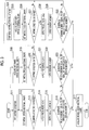
- Fig. 3 is a diagram for illustrating an example of a control operation of the design device according to the embodiment of the invention.
- Figs. 4 to 9 are diagrams for illustrating examples relating to cross-sectional shapes of fuselages.
- a design device 1 is a device used for designing a fuselage of a flying body such as an aircraft, and designs a cross-sectional shape of the fuselage, for example.
- a fuselage 5 that is a design target will be described with reference to Fig. 2 .
- the fuselage 5 is formed to extend in a roll axis direction that is a length direction.
- Fig. 2 shows a section taken on a plane perpendicular to the roll axis direction of the fuselage 5. Accordingly, in Fig. 2 , the roll axis direction is a front-back direction (a direction vertical to a paper plane in Fig. 2 ), a pitch axis direction perpendicular to the roll axis direction is a horizontal direction in Fig. 2 , and a yaw axis direction perpendicular to the roll axis direction and the pitch axis direction is a vertical direction in Fig. 2 .
- the fuselage 5 is formed to have a non-circular cross-section, and specifically, is formed in an approximately elliptical shape in which the pitch axis direction is a long axis direction and the yaw axis direction is a short axis direction. That is, the fuselage 5 is formed in a non-circular shape that is a flat annular shape in the pitch axis direction.
- the fuselage 5 includes a fuselage frame and a skin (which are not shown).
- the fuselage 5 is provided therein with a floor beam 6, and rods 7 that connect the floor beam 6 and the fuselage 5.
- the floor beam 6 is provided to extend in parallel with the pitch axis direction (long axis direction), and opposite portions thereof are connected to an inner circumferential surface of the fuselage 5.
- the rods 7 are provided on both sides with the center of the floor beam 6 in the pitch axis direction being interposed therebetween, and respectively connect a lower surface of the floor beam 6 and the inner circumferential surface of the fuselage 5.
- the fuselage 5 is formed to secure a predetermined space in an inner portion thereof.
- the predetermined space includes a seat space 10 in which seats are provided, a passage space 11 through which a person can pass, an overhead bin space 12 in which baggage is accommodated, a cargo compartment space 13 that accommodates cargos, and the like.
- Three seat spaces 10 are provided above the floor beam 6.
- the three seat spaces 10 are respectively provided on opposite sides and at the center in the pitch axis direction.
- Two passage spaces 11 are provided above the floor beam 6, and are respectively provided to be disposed between the three seat spaces 10.
- Two overhead bin spaces 12 are provided above the floor beam 6, and are provided above the seat spaces 10 on opposite sides in the pitch axis direction.
- the cargo compartment space 13 is provided below the floor beam 6, and is provided between the rods 7 on opposite sides in the pitch axis direction.
- an external pressure of the fuselage 5 is lowered compared with an internal pressure thereof, and a pressurized load is applied from the inside to the outside due to a pressure difference between the internal pressure and the external pressure.
- the fuselage 5 is designed by the design device 1 described below so that a bending moment generated due to the application of the pressurized load. Further, in the fuselage 5, a spatial limiting condition for securing the above-mentioned predetermined spaces is set in design.
- the design device 1 is a device that is operable by a designer, and design of the fuselage 5 is performed on the design device 1.
- the design device 1 includes an input section 21, a display section 22, a processing section 23, and a storage section 24.
- the design device 1 is not particularly limited to a configuration in which a singular device is provided, and may employ a configuration in which plural devices cooperate with each other.
- the input section 21 includes an input device such as a keyboard or a mouse, and outputs a signal corresponding to an operation to be performed with respect to the input device from a user to the processing section 23.
- the display section 22 includes a display device such as a display, and displays a screen including a variety of information such as letters or figures on the basis of a display signal output from the processing section 23.
- the processing section 23 includes an integrated circuit such as a central processing unit (CPU) and a memory that is a work area, and executes various programs using such hardware resources to execute various steps. Specifically, the processing section 23 reads out a program stored in the storage section 24 to expand the result into the memory, and causes the CPU to execute a command included in the program expanded in the memory to execute various steps.
- CPU central processing unit
- the storage section 24 includes a non-volatile storage device such as a magnetic storage device or a semiconductor storage device, and stores a variety of programs and data.
- the program stored in the storage section 24 includes a design program 28 for designing the fuselage 5.
- the data stored in the storage section 24 includes limiting condition data 29 that is data relating to a limiting condition.
- the design device 1 having such a configuration is able to design the fuselage 5 as the processing section 23 executes the design program 28.
- a control operation of the design device 1 will be described with reference to Fig. 3 .
- Fig. 3 a control operation relating to a design of a cross-sectional shape of the fuselage 5 using the design device 1 is shown.
- a designer operates the input section 21 of the design device 1 to input a limiting condition of the fuselage 5.
- a limiting condition spaces of the seat spaces 10, the passage spaces 11, the overhead bin spaces 12, the cargo compartment space 13, and the like are set.
- the processing section 23 of the design device 1 sets the input limiting condition in accordance with a signal input through the input section 21 based on the operation of the designer, generates limiting condition data 29 on the basis of the input limiting condition, and retains the result in the storage section 24 (step S11: limiting condition setting step).
- the designer operates the input section 21 of the design device 1 to input an initial cross-sectional shape that is a shape of an initial cross-section of the fuselage 5.
- the processing section 23 of the design device 1 sets the initial cross-sectional shape of the input fuselage 5 in accordance with a signal input through the input section 21 based on the operation of the designer (step S12: initial setting step).
- the set initial cross-sectional shape of the fuselage 5 is generated and set as an analysis model that is a model for performing analysis.
- Fig. 4 shows an initial cross-sectional shape that is an analysis model set by the initial setting step S12.
- a limiting condition is set in the initial cross-sectional shape shown in Fig. 4 .
- step S13 limiting condition determination step. That is, the design device 1 determines whether it is possible to secure the spaces of the seat spaces 10, the passage spaces 11, the overhead bin spaces 12, the cargo compartment space 13, and the like, inside the initial cross-sectional shape. In a case where it is determined that the initial cross-sectional shape does not satisfy the limiting condition (No in step S13), the procedure proceeds to step S12, and the design device 1 makes a request for re-setting of the initial cross-sectional shape.
- step S14 load application step.
- an analysis step is performed in a state where the pressurized load is applied to the initial cross-sectional shape that is the analysis model. Further, the design device 1 derives a bending moment generated in the fuselage 5 as an analysis processing result (step S15).
- Fig. 5 shows the fuselage 5 after the pressurized load is applied in step S14.
- a bending moment M is generated in the fuselage 5 after the pressurized load is applied in step S14.
- the bending moment M shown in Fig. 5 shows a value at each position along an outer circumference of the fuselage 5, in which the outside of the fuselage represents a positive value and the inside of the fuselage represents a negative value, using the position on the outer circumference of the fuselage 5 as a reference (zero).
- the magnitude of the value of the bending moment M is indicated by a distance from the position on the outer circumference of the fuselage 5, in which as the distance becomes larger, a larger bending moment is generated.
- the bending moment M has a distribution in which a positive value becomes large in an upper portion of the fuselage 5 in the yaw axis direction and in portions of the fuselage 5 on opposite sides of the floor beam 6. Further, the bending moment M has a distribution in which a negative value becomes large in portions between the upper portion of the fuselage 5 and the portions of the fuselage 5 on the opposite sides of the floor beam 6.
- the design device 1 determines whether the derived bending moment is equal to or smaller than a predetermined regulated bending moment (step S16: confirmation step).
- the regulated bending moment is set as an allowable value at which the bending moment generated along a circumferential direction of the fuselage 5 is allowable.
- the regulated bending moment may be set as a value at which the bending moment generated along the circumferential direction of the fuselage 5 becomes uniform.
- the design device 1 acquires the initial cross-sectional shape as a design cross-sectional shape (step S17: design shape setting step), and terminates the series of control operations.
- the design device 1 acquires a cross-sectional shape of the fuselage 5 after deformation obtained by application of a pressurized load (step S18). Further, the design device 1 re-sets the obtained cross-sectional shape of the fuselage 5 after deformation as an initial cross-sectional shape (step S19: initial setting step).
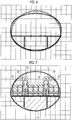
- Fig. 6 shows a cross-sectional shape ( ⁇ ) of the fuselage 5 before deformation and a cross-sectional shape ( ⁇ ) of the fuselage 5 after deformation.
- the cross-sectional shape ( ⁇ ) of the fuselage 5 before deformation corresponds to the initial cross-sectional shape set in step S12
- the cross sectional shape ( ⁇ ) of the fuselage 5 after deformation corresponds to the initial cross-sectional shape set in step S19.
- the approximately elliptical fuselage 5 becomes a shape close to a circle. Accordingly, the design cross-sectional shape may easily become a shape close to a circle compared with the initial cross-sectional shape.
- step S20 limiting condition determination step.
- a limiting condition is set in the initial cross-sectional shape that becomes the cross-sectional shape of the fuselage 5 after deformation. Since step S20 is the same step as step S13, description thereof will not be repeated.
- the design device 1 executes processes from step S21 to step S23. Since step S21 to step S23 are the same as step S14 to step S16, description thereof will not be repeated.
- step S24 rigidity adjustment step. That is, the designer operates the input section 21 of the design device 1 to adjust the rigidity distribution of the initial cross-sectional shape of the fuselage 5 to satisfy the limiting condition.
- the processing section 23 of the design device 1 sets the rigidity distribution after adjustment with respect to the initial cross-sectional shape of the fuselage 5 in accordance with an input signal through the input section 21 based on the operation of the designer.
- the design device 1 applies a pressurized load to the cross-sectional shape after the rigidity distribution is adjusted, and acquires a cross-sectional shape after deformation due to the application of the pressurized load (step S25). Then, the design device 1 re-sets the cross-sectional shape of the fuselage 5 after the rigidity distribution is adjusted as an initial cross-sectional shape (step S26: initial setting step).
- Fig. 8 shows a cross-sectional shape ( ⁇ ) of the fuselage 5 before a rigidity distribution is adjusted and a cross-sectional shape (0) of the deformed fuselage 5 after the rigidity distribution is adjusted. Further, the cross-sectional shape (0) that is re-set in step S26 becomes the cross-sectional shape of the deformed fuselage 5 after the rigidity distribution is adjusted.
- step S27 limiting condition determination step. Since step S27 is the same step as step S13 and step S20, description thereof will not be repeated. In a case where it is determined that the initial cross-sectional shape does not satisfy the limiting condition (No in step S27), the procedure proceeds to step S24, and the design device 1 requests the designer to re-adjust the rigidity distribution.
- the designer operates the input section 21 of the design device 1 to re-adjust the rigidity distribution in the initial cross-sectional shape of the fuselage 5 to satisfy the limiting condition.
- step S27 in a case where it is determined that the initial cross-sectional shape satisfies the limiting condition (Yes in step S27), the design device 1 executes processes from step S28 to step S30. Since step S28 to step S30 are also the same as step S14 to step S16, and step S21 to step S23, description thereof will not be repeated.
- step S30 in a case where it is determined the derived bending moment is larger than the regulated bending moment (No in step S30), the procedure proceeds to step S24, and the design device 1 requests re-adjustment of the rigidity distribution.
- step S30 in a case where it is determined that the derived bending moment is equal to or smaller than the regulated bending moment (Yes in step S30), the design device 1 obtains the initial cross-sectional shape as a design cross-sectional shape (step S17: design shape setting step), and terminates the series of control operations.
- Fig. 9 shows the fuselage 5 after the pressurized load is applied in step S28.
- a bending moment M is generated, but the bending moment is suppressed compared with the bending moment M shown in Fig. 5 , generated in step S14. That is, the bending moment M shown in Fig. 9 has a distribution in which a positive value becomes small (the distance from the outer surface of the fuselage is short) in the upper portion of the fuselage 5 in the yaw axis direction and in the portions of the fuselage 5 on the opposite sides of the floor beam 6, compared with the bending moment M shown in Fig. 5 .
- the bending moment M has a distribution in which a negative value becomes small (the distance from the outer surface of the fuselage is short) in the portions between the upper portion of the fuselage 5 and the portions of the fuselage 5 on the opposite sides of the floor beam 6, compared with the bending moment M shown in Fig. 5 .
- the bending moment M generated by the adjustment of the rigidity distribution becomes a sufficiently small value, compared with the bending moment M shown in Fig. 5 .
- the fuselage 5 having the design cross-sectional shape has a shape in which a large bending moment M is not easily generated with respect to the pressurized load.
- limiting condition determination steps S13, S20, and S27 it is possible to determine whether a design cross-sectional shape satisfies a spatial limiting condition, and thus, it is possible to design the fuselage 5 having a design cross-sectional shape that satisfies such a limiting condition.
- the rigidity adjustment step S24 by performing the rigidity adjustment step S24, it is possible to change a design cross-sectional shape into a design cross-sectional shape that satisfies a limiting condition.
- rigidity of a part of the fuselage 5 having a design cross-sectional shape is adjusted to become high, by increasing a plate thickness of a part of a skin or a frame that forms the fuselage 5 in a manufacturing stage of the fuselage 5, it is possible to realize the designed fuselage 5.
- the bending moment M is acquired by executing an analysis step of applying a pressurized load to an initial cross-sectional shape as an analysis model, but the bending moment M may be acquired by experimentally applying a pressurized load to the fuselage 5 as a test piece having an initial cross-sectional shape.
- the fuselage 5 is designed to have a design cross-sectional shape in which a bending moment is suppressed in a fuselage having an approximately elliptical cross-sectional shape in which a pitch axis direction is a long axis direction and a yaw axis direction is a short axis direction, but it is also possible to apply the same design with respect to all fuselages having non-circular shapes other than the approximately elliptical shape.
- Figs. 10 to 12 are diagrams of an example relating to a cross-sectional shape of a fuselage.
- the fuselage 5 shown in Figs. 10 to 12 has an approximately elliptical cross-sectional shape in which the pitch axis direction is the short axis direction and the yaw axis direction is the long axis direction.
- the fuselage 5 shown in Figs. 10 to 12 similarly, it is possible to apply the same design using the cross-sectional shape design method of the fuselage shown in Fig. 3 .
- FIG. 10 an initial cross-sectional shape as an analysis model set by the initial setting step S12 is shown. Further, in the initial cross-sectional shape shown in Fig. 10 , a limiting condition set in the limiting condition setting step S11 is shown.
- the fuselage 5 after the load application step S14 is performed becomes the fuselage 5 shown in Fig. 11 .
- a bending moment M is generated in the fuselage 5 after the pressurized load is applied.
- the bending moment M becomes large in portions of the fuselage 5 on the opposite sides of the floor beam 6.
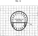
- the cross-sectional shape of the fuselage 5 shown in Fig. 12 represents a design cross-sectional shape acquired in the design shape setting step S17.
- the design cross-sectional shape of the fuselage 5 shown in Fig. 12 is a cross-sectional shape obtained by appropriately executing the processes from step S18 to step S23 or the processes from step S24 to step S30.
- the fuselage 5 having the design cross-sectional shape acquired in the design shape setting step S17 a bending moment M is generated, but the bending moment is suppressed compared with the bending moment M shown in Fig. 5 , generated in step S14.
- the fuselage 5 having an approximately elliptical cross-section in which the pitch axis direction is the short axis direction and the yaw axis direction is the long axis direction similarly, it is possible to design a fuselage 5 having a non-circular cross-section in which a generated bending moment M is suppressed.
Landscapes
- Engineering & Computer Science (AREA)
- Aviation & Aerospace Engineering (AREA)
- Physics & Mathematics (AREA)
- Geometry (AREA)
- Theoretical Computer Science (AREA)
- Mechanical Engineering (AREA)
- General Physics & Mathematics (AREA)
- Transportation (AREA)
- Manufacturing & Machinery (AREA)
- Mathematical Optimization (AREA)
- Computer Hardware Design (AREA)
- Evolutionary Computation (AREA)
- General Engineering & Computer Science (AREA)
- Pure & Applied Mathematics (AREA)
- Mathematical Analysis (AREA)
- Computational Mathematics (AREA)
- Automation & Control Theory (AREA)
- Body Structure For Vehicles (AREA)
Abstract
Description
- The present invention relates to a design method, a design device, and a design program for designing a cross-sectional shape of a fuselage of a flying body such as an aircraft.
- In the related art, an aircraft having a cross-section of an approximately elliptical shape in which a width direction of a fuselage is a long axis direction and a height direction (vertical direction) of the fuselage is a short axis direction is known as a fuselage of the aircraft (for example, see PTL 1).
- [PTL 1]
U.S. Patent No. 8,292,226 - In a case where a cross-sectional shape of a fuselage of a flying body such as an aircraft is a non-circular shape such as an elliptical shape as shown in PTL 1, in a case where a pressurized load is applied from an inside of the fuselage to an outside thereof due to a pressure difference between the inside and the outside of the fuselage in the sky, a larger bending moment is generated in the fuselage, compared with a fuselage having a circular cross-section. In a case where reinforcement against the bending moment is performed, a weight of the fuselage increases due to the reinforcement. Accordingly, in order to reduce a structural weight of the fuselage, it is necessary to design the fuselage having the non-circular cross-section such that a generated bending moment is small.
- Accordingly, an object of the invention is to provide a design method, a design device, and a design program capable of designing a fuselage in which a generated bending moment is suppressed, even in a fuselage having a non-circular cross-sectional shape.
- According to an aspect of the invention, there is provided a method for designing a cross-sectional shape of a fuselage taken on a plane perpendicular to a length direction of a flying body having the fuselage that extends in the length direction, in which the cross-sectional shape of the fuselage is a non-circular shape, the method including: an initial setting step of setting an initial cross-sectional shape that is a shape of an initial cross-section of the fuselage; a load application step of applying a pressurized load to the fuselage having the initial cross-sectional shape; and a design shape setting step of acquiring a cross-sectional shape of the fuselage after the pressurized load is applied as a design cross-sectional shape of the fuselage.
- Further, according to another aspect of the invention, there is provided a design device that designs a cross-sectional shape of a fuselage taken on a plane perpendicular to a length direction of a flying body having the fuselage that extends in the length direction, in which the cross-sectional shape of the fuselage is a non-circular shape, the design device executing: an initial setting step of setting an initial cross-sectional shape that is a shape of an initial cross-section of the fuselage; and a design shape setting step of acquiring a cross-sectional shape of the fuselage after a pressurized load is applied to the fuselage having the initial cross-sectional shape as a design cross-sectional shape of the fuselage.
- In addition, according to still another aspect of the invention, there is provided a design program executed by a design device for designing a cross-sectional shape of a fuselage taken on a plane perpendicular to a length direction of a flying body having the fuselage that extends in the length direction, in which the cross-sectional shape of the fuselage is a non-circular shape, the design program causing the design device to execute: an initial setting step of setting an initial cross-sectional shape that is a shape of an initial cross-section of the fuselage; and a design shape setting step of acquiring a cross-sectional shape of the fuselage after a pressurized load is applied to the fuselage having the initial cross-sectional shape as a design cross-sectional shape of the fuselage.
- According to these configurations, by employing a cross-sectional shape after a pressurized load is applied as a design cross-sectional shape, it is possible to design a fuselage having a non-circular cross-sectional shape in which a generated bending moment is suppressed. That is, even in a case where a large bending moment is generated when a pressurized load is applied to a fuselage having an initial cross-sectional shape, by employing a cross-sectional shape of the fuselage when the pressurized load is applied as a design cross-sectional shape, the fuselage having the design cross-sectional shape has a shape in which a large bending moment is not easily generated with respect to the pressurized load. In a case where a pressurized load is applied, since the fuselage having a non-circular cross-sectional shape easily becomes a shape close to a circle, the design cross-sectional shape may easily become a shape close to a circle compared with the initial cross-sectional shape.
- Further, it is preferable that the method further includes a confirmation step of determining whether a bending moment generated in the fuselage obtained in the load application step is equal to or smaller than a predetermined regulated bending moment, in which in a case where it is determined in the confirmation step that the bending moment is equal to or smaller than the regulated bending moment, the cross-sectional shape of the fuselage before the pressurized load is applied is acquired as the design cross-sectional shape of the fuselage, in the design shape setting step, and in a case where it is determined in the confirmation step that the bending moment is larger than the regulated bending moment, the cross-sectional shape of the fuselage after the pressurized load is applied is re-set as the initial cross-sectional shape.
- According to this configuration, it is possible to confirm that a bending moment generated in a design cross-sectional shape is smaller than a regulated bending moment, and it is possible to design a fuselage having a design cross-sectional shape in which the generated bending moment is suppressed.
- Further, it is preferable that the method further includes: a limiting condition setting step of setting a spatial limiting condition inside the fuselage; and a limiting condition determination step of determining whether the design cross-sectional shape of the fuselage satisfies the limiting condition.
- According to this configuration, it is possible to determine whether a design cross-sectional shape satisfies a spatial limiting condition, and thus, it is possible to design a fuselage having a design cross-sectional shape that satisfies such a limiting condition.
- In addition, it is preferable that the method further includes: a rigidity adjustment step of adjusting, in a case where it is determined in the limiting condition determination step that the design cross-sectional shape of the fuselage does not satisfy the limiting condition, a rigidity distribution in the design cross-sectional shape of the fuselage so that the design cross-sectional shape of the fuselage satisfies the limiting condition.
- According to this configuration, by adjusting the rigidity distribution of the fuselage having the design cross-sectional shape, it is possible to change a design cross-sectional shape into a design cross-sectional shape that satisfies a limiting condition. In a case where rigidity of a part of the fuselage having a design cross-sectional shape is adjusted to become high, by increasing a plate thickness of a part of a skin or a frame that forms the fuselage in a manufacturing stage of the fuselage, it is possible to realize a designed fuselage.
-
-
Fig. 1 is a configuration diagram showing control blocks of a design device according to an embodiment of the invention. -
Fig. 2 is a sectional view of a fuselage taken on a plane perpendicular to a roll axis direction. -
Fig. 3 is a diagram for illustrating an example of a control operation of the design device according to the embodiment of the invention. -
Fig. 4 is a diagram for illustrating an example relating to a cross-sectional shape of a fuselage. -
Fig. 5 is a diagram for illustrating an example relating to a cross-sectional shape of a fuselage. -
Fig. 6 is a diagram for illustrating an example relating to a cross-sectional shape of a fuselage. -
Fig. 7 is a diagram for illustrating an example relating to a cross-sectional shape of a fuselage. -
Fig. 8 is a diagram for illustrating an example relating to a cross-sectional shape of a fuselage. -
Fig. 9 is a diagram for illustrating an example relating to a cross-sectional shape of a fuselage. -
Fig. 10 is a diagram for illustrating an example relating to a cross-sectional shape of a fuselage. -
Fig. 11 is a diagram for illustrating an example relating to a cross-sectional shape of a fuselage. -
Fig. 12 is a diagram for illustrating an example relating to a cross-sectional shape of a fuselage. - Hereinafter, an embodiment according to the invention will be described in detail with reference to the accompanying drawings. The embodiments do not limit the invention. Further, components in the embodiment described below include easily replaceable components from the viewpoint of those skilled in the art, or include substantially the same components. Further, the components described below may be appropriately combined. Further, in a case where there are plural embodiments, the respective embodiments may be combined.
-
Fig. 1 is a configuration diagram showing control blocks of a design device according to an embodiment of the invention.Fig. 2 is a sectional view of a fuselage taken on a plane perpendicular to a roll axis direction.Fig. 3 is a diagram for illustrating an example of a control operation of the design device according to the embodiment of the invention.Figs. 4 to 9 are diagrams for illustrating examples relating to cross-sectional shapes of fuselages. - A design device 1 according to the embodiment is a device used for designing a fuselage of a flying body such as an aircraft, and designs a cross-sectional shape of the fuselage, for example. First, a
fuselage 5 that is a design target will be described with reference toFig. 2 . - The
fuselage 5 is formed to extend in a roll axis direction that is a length direction.Fig. 2 shows a section taken on a plane perpendicular to the roll axis direction of thefuselage 5. Accordingly, inFig. 2 , the roll axis direction is a front-back direction (a direction vertical to a paper plane inFig. 2 ), a pitch axis direction perpendicular to the roll axis direction is a horizontal direction inFig. 2 , and a yaw axis direction perpendicular to the roll axis direction and the pitch axis direction is a vertical direction inFig. 2 . - As shown in
Fig. 2 , thefuselage 5 is formed to have a non-circular cross-section, and specifically, is formed in an approximately elliptical shape in which the pitch axis direction is a long axis direction and the yaw axis direction is a short axis direction. That is, thefuselage 5 is formed in a non-circular shape that is a flat annular shape in the pitch axis direction. Thefuselage 5 includes a fuselage frame and a skin (which are not shown). - Further, the
fuselage 5 is provided therein with afloor beam 6, androds 7 that connect thefloor beam 6 and thefuselage 5. Thefloor beam 6 is provided to extend in parallel with the pitch axis direction (long axis direction), and opposite portions thereof are connected to an inner circumferential surface of thefuselage 5. Therods 7 are provided on both sides with the center of thefloor beam 6 in the pitch axis direction being interposed therebetween, and respectively connect a lower surface of thefloor beam 6 and the inner circumferential surface of thefuselage 5. - In addition, the
fuselage 5 is formed to secure a predetermined space in an inner portion thereof. The predetermined space includes aseat space 10 in which seats are provided, apassage space 11 through which a person can pass, anoverhead bin space 12 in which baggage is accommodated, acargo compartment space 13 that accommodates cargos, and the like. Threeseat spaces 10 are provided above thefloor beam 6. The threeseat spaces 10 are respectively provided on opposite sides and at the center in the pitch axis direction. Twopassage spaces 11 are provided above thefloor beam 6, and are respectively provided to be disposed between the threeseat spaces 10. Twooverhead bin spaces 12 are provided above thefloor beam 6, and are provided above theseat spaces 10 on opposite sides in the pitch axis direction. Thecargo compartment space 13 is provided below thefloor beam 6, and is provided between therods 7 on opposite sides in the pitch axis direction. - As an aircraft having the
fuselage 5 configured as described above flies in the sky, an external pressure of thefuselage 5 is lowered compared with an internal pressure thereof, and a pressurized load is applied from the inside to the outside due to a pressure difference between the internal pressure and the external pressure. Thefuselage 5 is designed by the design device 1 described below so that a bending moment generated due to the application of the pressurized load. Further, in thefuselage 5, a spatial limiting condition for securing the above-mentioned predetermined spaces is set in design. - Next, the design device 1 will be described with reference to
Fig. 1 . As shown inFig. 1 , the design device 1 is a device that is operable by a designer, and design of thefuselage 5 is performed on the design device 1. The design device 1 includes aninput section 21, adisplay section 22, aprocessing section 23, and astorage section 24. The design device 1 is not particularly limited to a configuration in which a singular device is provided, and may employ a configuration in which plural devices cooperate with each other. - The
input section 21 includes an input device such as a keyboard or a mouse, and outputs a signal corresponding to an operation to be performed with respect to the input device from a user to theprocessing section 23. Thedisplay section 22 includes a display device such as a display, and displays a screen including a variety of information such as letters or figures on the basis of a display signal output from theprocessing section 23. - The
processing section 23 includes an integrated circuit such as a central processing unit (CPU) and a memory that is a work area, and executes various programs using such hardware resources to execute various steps. Specifically, theprocessing section 23 reads out a program stored in thestorage section 24 to expand the result into the memory, and causes the CPU to execute a command included in the program expanded in the memory to execute various steps. - The
storage section 24 includes a non-volatile storage device such as a magnetic storage device or a semiconductor storage device, and stores a variety of programs and data. The program stored in thestorage section 24 includes adesign program 28 for designing thefuselage 5. Further, the data stored in thestorage section 24 includes limitingcondition data 29 that is data relating to a limiting condition. - The design device 1 having such a configuration is able to design the
fuselage 5 as theprocessing section 23 executes thedesign program 28. - Then, a control operation of the design device 1 will be described with reference to
Fig. 3 . InFig. 3 , a control operation relating to a design of a cross-sectional shape of thefuselage 5 using the design device 1 is shown. - As shown in
Fig. 3 , first, a designer operates theinput section 21 of the design device 1 to input a limiting condition of thefuselage 5. As the limiting condition, spaces of theseat spaces 10, thepassage spaces 11, theoverhead bin spaces 12, thecargo compartment space 13, and the like are set. Theprocessing section 23 of the design device 1 sets the input limiting condition in accordance with a signal input through theinput section 21 based on the operation of the designer, generates limitingcondition data 29 on the basis of the input limiting condition, and retains the result in the storage section 24 (step S11: limiting condition setting step). - Subsequently, the designer operates the
input section 21 of the design device 1 to input an initial cross-sectional shape that is a shape of an initial cross-section of thefuselage 5. Theprocessing section 23 of the design device 1 sets the initial cross-sectional shape of theinput fuselage 5 in accordance with a signal input through theinput section 21 based on the operation of the designer (step S12: initial setting step). The set initial cross-sectional shape of thefuselage 5 is generated and set as an analysis model that is a model for performing analysis. -
Fig. 4 shows an initial cross-sectional shape that is an analysis model set by the initial setting step S12. Here, a limiting condition is set in the initial cross-sectional shape shown inFig. 4 . - After the initial cross-sectional shape is set, the design device 1 determines whether the initial cross-sectional shape satisfies the limiting condition (step S13: limiting condition determination step). That is, the design device 1 determines whether it is possible to secure the spaces of the
seat spaces 10, thepassage spaces 11, theoverhead bin spaces 12, thecargo compartment space 13, and the like, inside the initial cross-sectional shape. In a case where it is determined that the initial cross-sectional shape does not satisfy the limiting condition (No in step S13), the procedure proceeds to step S12, and the design device 1 makes a request for re-setting of the initial cross-sectional shape. - On the other hand, in a case where it is determined that the initial cross-sectional shape satisfies the limiting condition (Yes in step S13), the design device 1 applies a pressurized load to the
fuselage 5 having the initial cross-sectional shape (step S14: load application step). In the load application step S14, an analysis step is performed in a state where the pressurized load is applied to the initial cross-sectional shape that is the analysis model. Further, the design device 1 derives a bending moment generated in thefuselage 5 as an analysis processing result (step S15). -
Fig. 5 shows thefuselage 5 after the pressurized load is applied in step S14. In thefuselage 5 after the pressurized load is applied, a bending moment M is generated. The bending moment M shown inFig. 5 shows a value at each position along an outer circumference of thefuselage 5, in which the outside of the fuselage represents a positive value and the inside of the fuselage represents a negative value, using the position on the outer circumference of thefuselage 5 as a reference (zero). Further, the magnitude of the value of the bending moment M is indicated by a distance from the position on the outer circumference of thefuselage 5, in which as the distance becomes larger, a larger bending moment is generated. The bending moment M has a distribution in which a positive value becomes large in an upper portion of thefuselage 5 in the yaw axis direction and in portions of thefuselage 5 on opposite sides of thefloor beam 6. Further, the bending moment M has a distribution in which a negative value becomes large in portions between the upper portion of thefuselage 5 and the portions of thefuselage 5 on the opposite sides of thefloor beam 6. - Subsequently, the design device 1 determines whether the derived bending moment is equal to or smaller than a predetermined regulated bending moment (step S16: confirmation step). Here, the regulated bending moment is set as an allowable value at which the bending moment generated along a circumferential direction of the
fuselage 5 is allowable. The regulated bending moment may be set as a value at which the bending moment generated along the circumferential direction of thefuselage 5 becomes uniform. In a case where it is determined that the derived bending moment is equal to or smaller than the regulated bending moment (Yes in step S16), the design device 1 acquires the initial cross-sectional shape as a design cross-sectional shape (step S17: design shape setting step), and terminates the series of control operations. - On the other hand, in a case where it is determined whether the derived bending moment is larger than the regulated bending moment (No in step S16), the design device 1 acquires a cross-sectional shape of the
fuselage 5 after deformation obtained by application of a pressurized load (step S18). Further, the design device 1 re-sets the obtained cross-sectional shape of thefuselage 5 after deformation as an initial cross-sectional shape (step S19: initial setting step). -
Fig. 6 shows a cross-sectional shape (■) of thefuselage 5 before deformation and a cross-sectional shape (○) of thefuselage 5 after deformation. The cross-sectional shape (■) of thefuselage 5 before deformation corresponds to the initial cross-sectional shape set in step S12, and the cross sectional shape (○) of thefuselage 5 after deformation corresponds to the initial cross-sectional shape set in step S19. As shown inFig. 6 , in a case where a pressurized load is applied, the approximatelyelliptical fuselage 5 becomes a shape close to a circle. Accordingly, the design cross-sectional shape may easily become a shape close to a circle compared with the initial cross-sectional shape. - In a case where the initial cross-sectional shape is set, the design device 1 determines whether the initial cross-sectional shape satisfies a limiting condition (step S20: limiting condition determination step). As shown in
Fig. 7 , in the initial cross-sectional shape that becomes the cross-sectional shape of thefuselage 5 after deformation, a limiting condition is set. Since step S20 is the same step as step S13, description thereof will not be repeated. In a case where it is determined that the initial cross-sectional shape satisfies the limiting condition (Yes in step S20), the design device 1 executes processes from step S21 to step S23. Since step S21 to step S23 are the same as step S14 to step S16, description thereof will not be repeated. - On the other hand, in a case where it is determined that the cross-sectional shape does not satisfy the limiting condition (No in step S20), the design device 1 adjusts a rigidity distribution of the initial cross-sectional shape (step S24: rigidity adjustment step). That is, the designer operates the
input section 21 of the design device 1 to adjust the rigidity distribution of the initial cross-sectional shape of thefuselage 5 to satisfy the limiting condition. Theprocessing section 23 of the design device 1 sets the rigidity distribution after adjustment with respect to the initial cross-sectional shape of thefuselage 5 in accordance with an input signal through theinput section 21 based on the operation of the designer. - Further, the design device 1 applies a pressurized load to the cross-sectional shape after the rigidity distribution is adjusted, and acquires a cross-sectional shape after deformation due to the application of the pressurized load (step S25). Then, the design device 1 re-sets the cross-sectional shape of the
fuselage 5 after the rigidity distribution is adjusted as an initial cross-sectional shape (step S26: initial setting step). -
Fig. 8 shows a cross-sectional shape (■) of thefuselage 5 before a rigidity distribution is adjusted and a cross-sectional shape (0) of thedeformed fuselage 5 after the rigidity distribution is adjusted. Further, the cross-sectional shape (0) that is re-set in step S26 becomes the cross-sectional shape of thedeformed fuselage 5 after the rigidity distribution is adjusted. - In a case where the initial cross-sectional shape is set, the design device 1 determines whether the initial cross-sectional shape satisfies the limiting condition (step S27: limiting condition determination step). Since step S27 is the same step as step S13 and step S20, description thereof will not be repeated. In a case where it is determined that the initial cross-sectional shape does not satisfy the limiting condition (No in step S27), the procedure proceeds to step S24, and the design device 1 requests the designer to re-adjust the rigidity distribution. In a case where the request of the re-adjustment of the rigidity distribution is output from the design device 1, the designer operates the
input section 21 of the design device 1 to re-adjust the rigidity distribution in the initial cross-sectional shape of thefuselage 5 to satisfy the limiting condition. - On the other hand, in a case where it is determined that the initial cross-sectional shape satisfies the limiting condition (Yes in step S27), the design device 1 executes processes from step S28 to step S30. Since step S28 to step S30 are also the same as step S14 to step S16, and step S21 to step S23, description thereof will not be repeated. In step S30, in a case where it is determined the derived bending moment is larger than the regulated bending moment (No in step S30), the procedure proceeds to step S24, and the design device 1 requests re-adjustment of the rigidity distribution.
- On the other hand, in step S30, in a case where it is determined that the derived bending moment is equal to or smaller than the regulated bending moment (Yes in step S30), the design device 1 obtains the initial cross-sectional shape as a design cross-sectional shape (step S17: design shape setting step), and terminates the series of control operations.
-
Fig. 9 shows thefuselage 5 after the pressurized load is applied in step S28. In thefuselage 5 after the pressurized load is applied, a bending moment M is generated, but the bending moment is suppressed compared with the bending moment M shown inFig. 5 , generated in step S14. That is, the bending moment M shown inFig. 9 has a distribution in which a positive value becomes small (the distance from the outer surface of the fuselage is short) in the upper portion of thefuselage 5 in the yaw axis direction and in the portions of thefuselage 5 on the opposite sides of thefloor beam 6, compared with the bending moment M shown inFig. 5 . Further, the bending moment M has a distribution in which a negative value becomes small (the distance from the outer surface of the fuselage is short) in the portions between the upper portion of thefuselage 5 and the portions of thefuselage 5 on the opposite sides of thefloor beam 6, compared with the bending moment M shown inFig. 5 . In this way, as shown inFig. 9 , the bending moment M generated by the adjustment of the rigidity distribution becomes a sufficiently small value, compared with the bending moment M shown inFig. 5 . - As described above, according to this embodiment, by employing a cross-sectional shape after a pressurized load is applied as a design cross-sectional shape, it is possible to design a
fuselage 5 having a non-circular cross-sectional shape in which a generated bending moment M is suppressed. That is, even in a case where a large bending moment M is generated when a pressurized load is applied to thefuselage 5 having an initial cross-sectional shape, by employing the cross-sectional shape of thefuselage 5 when the pressurized load is applied as a design cross-sectional shape, thefuselage 5 having the design cross-sectional shape has a shape in which a large bending moment M is not easily generated with respect to the pressurized load. - Further, according to this embodiment, by performing the confirmation steps S16, S23, and S30, it is possible to confirm that a bending moment generated in a design cross-sectional shape is smaller than a regulated bending moment, and it is possible to design the
fuselage 5 having a design cross-sectional shape in which a bending moment is suppressed. - In addition, according to this embodiment, as the approximately
elliptical fuselage 5 in which thefloor beam 6 is provided in parallel with the long axis direction, it is possible to design thefuselage 5 in which a bending moment is suppressed. - Further, according to this embodiment, by performing the limiting condition determination steps S13, S20, and S27, it is possible to determine whether a design cross-sectional shape satisfies a spatial limiting condition, and thus, it is possible to design the
fuselage 5 having a design cross-sectional shape that satisfies such a limiting condition. - Furthermore, according to this embodiment, by performing the rigidity adjustment step S24, it is possible to change a design cross-sectional shape into a design cross-sectional shape that satisfies a limiting condition. In a case where rigidity of a part of the
fuselage 5 having a design cross-sectional shape is adjusted to become high, by increasing a plate thickness of a part of a skin or a frame that forms thefuselage 5 in a manufacturing stage of thefuselage 5, it is possible to realize the designedfuselage 5. - In this embodiment, on the design device 1, the bending moment M is acquired by executing an analysis step of applying a pressurized load to an initial cross-sectional shape as an analysis model, but the bending moment M may be acquired by experimentally applying a pressurized load to the
fuselage 5 as a test piece having an initial cross-sectional shape. - Further, in this embodiment, on the design device 1, the
fuselage 5 is designed to have a design cross-sectional shape in which a bending moment is suppressed in a fuselage having an approximately elliptical cross-sectional shape in which a pitch axis direction is a long axis direction and a yaw axis direction is a short axis direction, but it is also possible to apply the same design with respect to all fuselages having non-circular shapes other than the approximately elliptical shape. - Specifically, as the non-circular fuselage, for example, there is a fuselage shown in
Figs. 10 to 12. Figs. 10 to 12 are diagrams of an example relating to a cross-sectional shape of a fuselage. Thefuselage 5 shown inFigs. 10 to 12 has an approximately elliptical cross-sectional shape in which the pitch axis direction is the short axis direction and the yaw axis direction is the long axis direction. In thefuselage 5 shown inFigs. 10 to 12 , similarly, it is possible to apply the same design using the cross-sectional shape design method of the fuselage shown inFig. 3 . - Here, in
Fig. 10 , an initial cross-sectional shape as an analysis model set by the initial setting step S12 is shown. Further, in the initial cross-sectional shape shown inFig. 10 , a limiting condition set in the limiting condition setting step S11 is shown. - With respect to the initial cross-sectional shape shown in
Fig. 10 , thefuselage 5 after the load application step S14 is performed becomes thefuselage 5 shown inFig. 11 . As shown inFig. 11 , in thefuselage 5 after the pressurized load is applied, a bending moment M is generated. The bending moment M becomes large in portions of thefuselage 5 on the opposite sides of thefloor beam 6. - The cross-sectional shape of the
fuselage 5 shown inFig. 12 represents a design cross-sectional shape acquired in the design shape setting step S17. The design cross-sectional shape of thefuselage 5 shown inFig. 12 is a cross-sectional shape obtained by appropriately executing the processes from step S18 to step S23 or the processes from step S24 to step S30. As shown inFig. 12 , thefuselage 5 having the design cross-sectional shape acquired in the design shape setting step S17, a bending moment M is generated, but the bending moment is suppressed compared with the bending moment M shown inFig. 5 , generated in step S14. - As described above, in the
fuselage 5 having an approximately elliptical cross-section in which the pitch axis direction is the short axis direction and the yaw axis direction is the long axis direction, similarly, it is possible to design afuselage 5 having a non-circular cross-section in which a generated bending moment M is suppressed. -
- 1
- design device
- 5
- fuselage
- 6
- floor beam
- 7
- rod
- 10
- seat space
- 11
- passage space
- 12
- overhead bin space
- 13
- cargo compartment space
- 21
- input section
- 22
- display section
- 23
- processing section
- 24
- storage section
- 28
- design program
- 29
- limiting condition data
Claims (6)
- A method for designing a cross-sectional shape of a fuselage taken on a plane perpendicular to a length direction of a flying body having the fuselage that extends in the length direction,
in which the cross-sectional shape of the fuselage is a non-circular shape,
the method comprising:an initial setting step of setting an initial cross-sectional shape that is a shape of an initial cross-section of the fuselage;a load application step of applying a pressurized load to the fuselage having the initial cross-sectional shape; anda design shape setting step of acquiring a cross-sectional shape of the fuselage after the pressurized load is applied as a design cross-sectional shape of the fuselage. - The method for designing a cross-sectional shape of a fuselage according to claim 1, further comprising:a confirmation step of determining whether a bending moment generated in the fuselage obtained in the load application step is equal to or smaller than a predetermined regulated bending moment,wherein in a case where it is determined in the confirmation step that the bending moment is equal to or smaller than the regulated bending moment, the cross-sectional shape of the fuselage before the pressurized load is applied is acquired as the design cross-sectional shape of the fuselage, in the design shape setting step, andin a case where it is determined in the confirmation step that the bending moment is larger than the regulated bending moment, the cross-sectional shape of the fuselage after the pressurized load is applied is re-set as the initial cross-sectional shape.
- The method for designing a cross-sectional shape of a fuselage according to claim 1 or 2, further comprising:a limiting condition setting step of setting a spatial limiting condition inside the fuselage; anda limiting condition determination step of determining whether the design cross-sectional shape of the fuselage satisfies the limiting condition.
- The method for designing a cross-sectional shape of a fuselage according to claim 3, further comprising:
a rigidity adjustment step of adjusting, in a case where it is determined in the limiting condition determination step that the design cross-sectional shape of the fuselage does not satisfy the limiting condition, a rigidity distribution in the design cross-sectional shape of the fuselage so that the design cross-sectional shape of the fuselage satisfies the limiting condition. - A design device that designs a cross-sectional shape of a fuselage taken on a plane perpendicular to a length direction of a flying body having the fuselage that extends in the length direction,
in which the cross-sectional shape of the fuselage is a non-circular shape,
the design device executing:an initial setting step of setting an initial cross-sectional shape that is a shape of an initial cross-section of the fuselage; anda design shape setting step of acquiring a cross-sectional shape of the fuselage after a pressurized load is applied to the fuselage having the initial cross-sectional shape as a design cross-sectional shape of the fuselage. - A design program executed by a design device for designing a cross-sectional shape of a fuselage taken on a plane perpendicular to a length direction of a flying body having the fuselage that extends in the length direction,
in which the cross-sectional shape of the fuselage is a non-circular shape,
the design program causing the design device to execute:an initial setting step of setting an initial cross-sectional shape that is a shape of an initial cross-section of the fuselage; anda design shape setting step of acquiring a cross-sectional shape of the fuselage after a pressurized load is applied to the fuselage having the initial cross-sectional shape as a design cross-sectional shape of the fuselage.
Applications Claiming Priority (2)
| Application Number | Priority Date | Filing Date | Title |
|---|---|---|---|
| JP2016105405A JP6768348B2 (en) | 2016-05-26 | 2016-05-26 | Fuselage cross-sectional shape design method, design equipment and design program |
| PCT/JP2017/015933 WO2017203910A1 (en) | 2016-05-26 | 2017-04-20 | Design method, design device, and design program for cross-sectional shape of fuselage |
Publications (2)
| Publication Number | Publication Date |
|---|---|
| EP3441312A1 true EP3441312A1 (en) | 2019-02-13 |
| EP3441312A4 EP3441312A4 (en) | 2019-04-03 |
Family
ID=60412559
Family Applications (1)
| Application Number | Title | Priority Date | Filing Date |
|---|---|---|---|
| EP17802508.6A Withdrawn EP3441312A4 (en) | 2016-05-26 | 2017-04-20 | Design method, design device, and design program for cross-sectional shape of fuselage |
Country Status (4)
| Country | Link |
|---|---|
| US (1) | US11526635B2 (en) |
| EP (1) | EP3441312A4 (en) |
| JP (1) | JP6768348B2 (en) |
| WO (1) | WO2017203910A1 (en) |
Cited By (1)
| Publication number | Priority date | Publication date | Assignee | Title |
|---|---|---|---|---|
| CN113761667A (en) * | 2021-09-26 | 2021-12-07 | 中国空气动力研究与发展中心高速空气动力研究所 | Empty weight estimation method for supersonic passenger plane |
Family Cites Families (11)
| Publication number | Priority date | Publication date | Assignee | Title |
|---|---|---|---|---|
| US7621482B2 (en) * | 2005-11-15 | 2009-11-24 | The Boeing Company | Weight optimized pressurizable aircraft fuselage structures having near elliptical cross sections |
| US8292226B2 (en) * | 2005-11-15 | 2012-10-23 | The Boeing Company | Weight-optimizing internally pressurized composite-body aircraft fuselages having near-elliptical cross sections |
| US7735779B2 (en) * | 2006-11-02 | 2010-06-15 | The Boeing Company | Optimized fuselage structure |
| US7861970B2 (en) | 2006-11-02 | 2011-01-04 | The Boeing Company | Fuselage structure including an integrated fuselage stanchion |
| US8831913B2 (en) * | 2009-06-10 | 2014-09-09 | Airbus Operations Limited | Method of design optimisation |
| US8616500B2 (en) * | 2011-03-04 | 2013-12-31 | The Boeing Company | Diamond shaped window for composite and/or metallic airframe |
| FR2981176B1 (en) | 2011-10-08 | 2013-11-29 | Eads Europ Aeronautic Defence | METHOD FOR OPTIMIZING THE TOLERANCING OF A SET OF FLEXIBLE PARTS SUBJECT TO EFFORTS |
| ES2404946B1 (en) | 2011-10-21 | 2014-09-02 | Airbus Operations S.L. | AIRCRAFT FUSELAGE RESISTANT TO IMPACT AND TOLERANT TO IMPROVED DAMAGE |
| EP2746155B1 (en) * | 2012-12-21 | 2015-07-08 | Bell Helicopter Textron Inc. | Helicopter skid landing gear |
| US9868135B2 (en) * | 2015-05-06 | 2018-01-16 | The Boeing Company | Aerodynamic microstructures having sub-microstructures |
| US10040534B2 (en) * | 2015-12-07 | 2018-08-07 | Bell Helicopter Textron Inc. | Fuselage to wing attachment |
-
2016
- 2016-05-26 JP JP2016105405A patent/JP6768348B2/en active Active
-
2017
- 2017-04-20 WO PCT/JP2017/015933 patent/WO2017203910A1/en not_active Ceased
- 2017-04-20 EP EP17802508.6A patent/EP3441312A4/en not_active Withdrawn
- 2017-04-20 US US16/099,468 patent/US11526635B2/en active Active
Cited By (1)
| Publication number | Priority date | Publication date | Assignee | Title |
|---|---|---|---|---|
| CN113761667A (en) * | 2021-09-26 | 2021-12-07 | 中国空气动力研究与发展中心高速空气动力研究所 | Empty weight estimation method for supersonic passenger plane |
Also Published As
| Publication number | Publication date |
|---|---|
| EP3441312A4 (en) | 2019-04-03 |
| US20190087530A1 (en) | 2019-03-21 |
| JP6768348B2 (en) | 2020-10-14 |
| US11526635B2 (en) | 2022-12-13 |
| WO2017203910A1 (en) | 2017-11-30 |
| JP2017210148A (en) | 2017-11-30 |
Similar Documents
| Publication | Publication Date | Title |
|---|---|---|
| JP5416410B2 (en) | Weight-optimized pressurizable aircraft fuselage structure with a near-elliptical cross section | |
| US10864872B2 (en) | Occupant airbag and control system for use in autonomous vehicles with retractable steering wheels | |
| CN105523166B (en) | Plate structure and related methods | |
| US8949087B2 (en) | System and method for structural analysis | |
| CN109515685B (en) | Aircraft takeoff trim using stabilizer and elevator | |
| Xu et al. | On the buckling and post-buckling of core-shell cylinders under thermal loading | |
| EP2112064A2 (en) | Spherical elastomeric bearing with improved shim thickness | |
| US11526635B2 (en) | Method, design device, and design program for cross-sectional shape of fuselage | |
| Xia et al. | Adaptive control for spacecraft rendezvous subject to actuator faults and saturations | |
| US12188849B2 (en) | Control surface load simulation apparatus having reaction force providing structure | |
| US20200189711A1 (en) | Aircraft fuselage structure having a grid-stiffened panel | |
| CN107066701A (en) | The model building method of dynamics experiment based on spacecraft | |
| EP2942269A1 (en) | Method for manufacturing a load bearing structure and such a load bearing structure | |
| US11845537B2 (en) | System and method for mitigating an effect of an excitation of a structural flexible mode of an aircraft | |
| US11577311B2 (en) | Punching tool of a sintering press and method therefor | |
| Gaudiller et al. | Adaptive active control of flexible structures subjected to rigid body displacements | |
| Teixeira Neto et al. | A new metamodel for reinforced panels under compressive loads and its application to the fuselage conception | |
| KR102203143B1 (en) | Automation system for sizing | |
| Sandridge | Demonstration of decomposition and optimization in the design of experimental space systems | |
| Dima et al. | Method for lightweight optimization for aerospace milled parts–case study for a helicopter pilot lightweight crashworthy seat side struts | |
| Aldosari et al. | Acceleration flight control for reduced gravity flight in large fixed-wing aircraft | |
| Schwinn | Applied parametrized and automated airframe modeling methods in the preliminary design phase | |
| US12606296B2 (en) | Aircraft modal suppression system | |
| JP7820801B2 (en) | Natural frequency adjustment program, natural frequency adjustment method, and natural frequency adjustment system | |
| Yu et al. | Load and control effects on crack growth in flexible aircraft |
Legal Events
| Date | Code | Title | Description |
|---|---|---|---|
| STAA | Information on the status of an ep patent application or granted ep patent |
Free format text: STATUS: THE INTERNATIONAL PUBLICATION HAS BEEN MADE |
|
| PUAI | Public reference made under article 153(3) epc to a published international application that has entered the european phase |
Free format text: ORIGINAL CODE: 0009012 |
|
| STAA | Information on the status of an ep patent application or granted ep patent |
Free format text: STATUS: REQUEST FOR EXAMINATION WAS MADE |
|
| 17P | Request for examination filed |
Effective date: 20181108 |
|
| AK | Designated contracting states |
Kind code of ref document: A1 Designated state(s): AL AT BE BG CH CY CZ DE DK EE ES FI FR GB GR HR HU IE IS IT LI LT LU LV MC MK MT NL NO PL PT RO RS SE SI SK SM TR |
|
| AX | Request for extension of the european patent |
Extension state: BA ME |
|
| A4 | Supplementary search report drawn up and despatched |
Effective date: 20190306 |
|
| RIC1 | Information provided on ipc code assigned before grant |
Ipc: B64F 5/00 20170101AFI20190228BHEP Ipc: B64C 1/06 20060101ALI20190228BHEP |
|
| DAV | Request for validation of the european patent (deleted) | ||
| DAX | Request for extension of the european patent (deleted) | ||
| STAA | Information on the status of an ep patent application or granted ep patent |
Free format text: STATUS: EXAMINATION IS IN PROGRESS |
|
| 17Q | First examination report despatched |
Effective date: 20200302 |
|
| GRAP | Despatch of communication of intention to grant a patent |
Free format text: ORIGINAL CODE: EPIDOSNIGR1 |
|
| STAA | Information on the status of an ep patent application or granted ep patent |
Free format text: STATUS: GRANT OF PATENT IS INTENDED |
|
| INTG | Intention to grant announced |
Effective date: 20201027 |
|
| RIN1 | Information on inventor provided before grant (corrected) |
Inventor name: MOMOSE, TIMOTHY CRAIG Inventor name: TANI, TAKAYUKI Inventor name: SUGETA, KIYOSHI Inventor name: KOZASA, TOSHIO Inventor name: AZUMA, TOSHIHIKO Inventor name: HATANO, MASATAKE Inventor name: MATSUHASHI, MASAHIKO Inventor name: MORISHIMA, SHUNICHI Inventor name: OJIKA, HITOSHI |
|
| STAA | Information on the status of an ep patent application or granted ep patent |
Free format text: STATUS: THE APPLICATION IS DEEMED TO BE WITHDRAWN |
|
| 18D | Application deemed to be withdrawn |
Effective date: 20210310 |