EP3441304A1 - Adaptive structural core for morphing panel structures - Google Patents
Adaptive structural core for morphing panel structures Download PDFInfo
- Publication number
- EP3441304A1 EP3441304A1 EP18195227.6A EP18195227A EP3441304A1 EP 3441304 A1 EP3441304 A1 EP 3441304A1 EP 18195227 A EP18195227 A EP 18195227A EP 3441304 A1 EP3441304 A1 EP 3441304A1
- Authority
- EP
- European Patent Office
- Prior art keywords
- core
- actuator
- adaptive structural
- attachment points
- structural core
- Prior art date
- Legal status (The legal status is an assumption and is not a legal conclusion. Google has not performed a legal analysis and makes no representation as to the accuracy of the status listed.)
- Granted
Links
- 230000003044 adaptive effect Effects 0.000 title claims abstract description 141
- 210000004027 cell Anatomy 0.000 claims description 107
- 238000000034 method Methods 0.000 claims description 36
- 210000002421 cell wall Anatomy 0.000 claims description 25
- 230000003042 antagnostic effect Effects 0.000 claims description 21
- 239000002131 composite material Substances 0.000 description 16
- 230000008859 change Effects 0.000 description 14
- 238000010586 diagram Methods 0.000 description 14
- 238000004519 manufacturing process Methods 0.000 description 10
- 238000013461 design Methods 0.000 description 8
- 238000006073 displacement reaction Methods 0.000 description 4
- 230000007246 mechanism Effects 0.000 description 4
- 238000005452 bending Methods 0.000 description 3
- 230000000694 effects Effects 0.000 description 3
- 238000005219 brazing Methods 0.000 description 2
- 238000005520 cutting process Methods 0.000 description 2
- 238000009826 distribution Methods 0.000 description 2
- 239000012530 fluid Substances 0.000 description 2
- 230000006870 function Effects 0.000 description 2
- 238000003698 laser cutting Methods 0.000 description 2
- 238000012423 maintenance Methods 0.000 description 2
- 239000002184 metal Substances 0.000 description 2
- XLYOFNOQVPJJNP-UHFFFAOYSA-N water Substances O XLYOFNOQVPJJNP-UHFFFAOYSA-N 0.000 description 2
- 238000003466 welding Methods 0.000 description 2
- RZVHIXYEVGDQDX-UHFFFAOYSA-N 9,10-anthraquinone Chemical compound C1=CC=C2C(=O)C3=CC=CC=C3C(=O)C2=C1 RZVHIXYEVGDQDX-UHFFFAOYSA-N 0.000 description 1
- 208000002197 Ehlers-Danlos syndrome Diseases 0.000 description 1
- 239000002033 PVDF binder Substances 0.000 description 1
- 229920000535 Tan II Polymers 0.000 description 1
- 229910045601 alloy Inorganic materials 0.000 description 1
- 239000000956 alloy Substances 0.000 description 1
- 238000010276 construction Methods 0.000 description 1
- 230000008602 contraction Effects 0.000 description 1
- 238000009760 electrical discharge machining Methods 0.000 description 1
- 238000009429 electrical wiring Methods 0.000 description 1
- 230000007613 environmental effect Effects 0.000 description 1
- 238000005530 etching Methods 0.000 description 1
- 230000008595 infiltration Effects 0.000 description 1
- 238000001764 infiltration Methods 0.000 description 1
- 238000003780 insertion Methods 0.000 description 1
- 230000037431 insertion Effects 0.000 description 1
- 238000009434 installation Methods 0.000 description 1
- 230000010354 integration Effects 0.000 description 1
- 238000003754 machining Methods 0.000 description 1
- 239000000463 material Substances 0.000 description 1
- 229910001092 metal group alloy Inorganic materials 0.000 description 1
- 239000007769 metal material Substances 0.000 description 1
- 230000004048 modification Effects 0.000 description 1
- 238000012986 modification Methods 0.000 description 1
- 230000004660 morphological change Effects 0.000 description 1
- 230000008520 organization Effects 0.000 description 1
- 238000005192 partition Methods 0.000 description 1
- 230000000737 periodic effect Effects 0.000 description 1
- 229920000642 polymer Polymers 0.000 description 1
- 229920002981 polyvinylidene fluoride Polymers 0.000 description 1
- 230000036316 preload Effects 0.000 description 1
- 230000008569 process Effects 0.000 description 1
- 238000009419 refurbishment Methods 0.000 description 1
- 239000011347 resin Substances 0.000 description 1
- 229920005989 resin Polymers 0.000 description 1
- 230000000717 retained effect Effects 0.000 description 1
- 230000002441 reversible effect Effects 0.000 description 1
- 230000001953 sensory effect Effects 0.000 description 1
- 238000010008 shearing Methods 0.000 description 1
- 239000007787 solid Substances 0.000 description 1
- 239000003381 stabilizer Substances 0.000 description 1
- 230000003068 static effect Effects 0.000 description 1
- 238000007514 turning Methods 0.000 description 1
Images


Classifications
-
- B—PERFORMING OPERATIONS; TRANSPORTING
- B64—AIRCRAFT; AVIATION; COSMONAUTICS
- B64C—AEROPLANES; HELICOPTERS
- B64C3/00—Wings
- B64C3/38—Adjustment of complete wings or parts thereof
- B64C3/44—Varying camber
- B64C3/48—Varying camber by relatively-movable parts of wing structures
-
- B—PERFORMING OPERATIONS; TRANSPORTING
- B64—AIRCRAFT; AVIATION; COSMONAUTICS
- B64C—AEROPLANES; HELICOPTERS
- B64C3/00—Wings
- B64C3/38—Adjustment of complete wings or parts thereof
- B64C3/44—Varying camber
- B64C2003/445—Varying camber by changing shape according to the speed, e.g. by morphing
Definitions
- the disclosure relates to morphing panel structures which are suitable for aerodynamic applications. More particularly, the disclosure relates to an adaptive structural core for morphing panel structures which are suitable for aerospace and other applications.
- Morphing panel structures may be useful in aerodynamic applications in which large pressure and temperature gradients or loads may be applied to an airfoil or other surface.
- the aerodynamic functionality of morphing panel structures may require a delicate balance between the flexibility and the structural support capabilities of the structures. Therefore, it may be desirable that morphing panel structures which are suitable for aerospace applications be resistant to out-of-plane bending or flexing deformation while remaining amenable to in-plane deformation.
- An adaptive structural core for a morphing panel structure is needed to facilitate resistance of the structure to out-of-plane bending or flexing deformation while enabling in-plane deformation of the structure.
- the disclosure is generally directed to an adaptive structural core for morphing panel structures which facilitates resistance of the structure to out-of-plane bending or flexing deformation while enabling in-plane deformation of the structure.
- An illustrative embodiment of the adaptive structural core includes a plurality of core members arranged in a repeating pattern, a plurality of actuator attachment points provided on the plurality of core members and at least one actuator engaging the plurality of actuator attachment points.
- the adaptive structural core may include a plurality of core members arranged in a repeating pattern of core cells each having a cell space; a plurality of actuator attachment points provided on the plurality of core members in the cell space; a first actuator provided in the cell space and engaging a first pair of the plurality of actuator attachment points; and a second actuator provided in the cell space and engaging a second pair of the plurality of actuator attachment points.
- the disclosure is further generally directed to an adaptive structural core method.
- An illustrative embodiment of the method includes providing a plurality of core members, arranging the plurality of core members in a repeating pattern and providing a plurality of actuator attachment points on the plurality of core members.
- the adaptive structural core for morphing panel structures may include plurality of intersecting core members arranged in a planar repeat pattern of core cells each having a cell space and a plurality of cell walls facing the cell space; a plurality of actuator attachment openings provided in the plurality of core members in the cell space; a first actuator provided diagonally in the cell space and engaging a first pair of the plurality of actuator attachment points; and a second actuator provided diagonally in the cell space and engaging a second pair of the plurality of actuator attachment points.
- Each of the first actuator and the second actuator adapted to exert forces on the cell walls in a selected one of a cooperative manner and an antagonistic manner.
- the adaptive structural core method may include providing a plurality of core members; forming an adaptive structural core by arranging the plurality of core members in a repeating pattern; providing a plurality of actuator attachment points on the plurality of core members; providing a plurality of actuators; attaching the actuators to the actuator attachment points on the core members; providing at least one composite facesheet on the plurality of core members; changing a shape of the adaptive structural core by operating the actuators in a cooperative manner; and stiffening the adaptive structural core by operating the actuators in an antagonistic manner.
- the disclosure is further generally directed to a method of adapting a structural core of a morphing panel structure.
- An illustrative embodiment of the method includes providing an adaptive structural core having a plurality of core cells, providing at least one actuator in the core cells of the adaptive structural core and adapting the adaptive structural core by actuation of the at least one actuator.
- an illustrative embodiment of the adaptive structural core for morphing panel structures is generally indicated by reference numeral 1.
- the adaptive structural core 1 may be part of a morphing panel structure 28.
- the adaptive structural core 1 may be adapted to impart stiffness or changes in shape to the morphing panel structure 28.
- At least one composite facesheet 29 may be provided on the adaptive structural core 1.
- the adaptive structural core 1 may be sandwiched between a pair of the composite facesheets 29, as shown in FIG. 1 .
- the morphing panel structure 28 may be amenable to a variety of applications.
- the morphing panel structure 28 may be part of an aircraft wing skin 40 ( FIG. 19 ) of an aircraft 94.
- the morphing panel structure 28 may be amenable to other applications including but not limited to winglets, bay doors, resizable compartments, stabilizers, control surfaces and turbine inlet and outlet nozzles, as well as non-aerospace applications.
- the adaptive structural core 1 may include multiple core members 3 which may be a metallic or composite material, for example and without limitation.
- the adaptive structural core 1 may be constructed in a web configuration in which the core members 3 intersect at core member junctions 5 ( FIG. 3 ).
- the adaptive structural core 1 may include a planar repeat unit structure 42 in a rhombus 42a ( FIG. 6A ) or parallelogram 42b ( FIG. 6b ) geometry.
- Multiple core cells 2, each having a cell space 6, may be defined by and between the intersecting core members 3.
- the core members 3 may have core walls 4 which face the core space 6 of each core cell 2.
- the core members 3 may be made with a series of stacked layers or even weaves or as a series of expanded strips that are bonded in narrow, periodic locations along the strips. As shown in FIG. 6C , in some embodiments, the core members 3 may be constructed as a "wine case partition" 44 (vertically interleaved strips). The core members 3 may be interlocked 46
- the adaptive structural core 1 may be made as a monolith or in assemble-able portions from metal alloys or composite materials, for example and without limitation, via machining, laser cutting, water jet cutting, EDM or etching, for example and without limitation.
- laser cutting or water jet cutting may be used to cut the strips or the core monolith.
- Various existing weave lay-ups and resin infiltration techniques may be used for making miniature core webs or assemble-able parts of the core structure.
- actuator attachment points 8 may be provided in the core members 3 to facilitate attachment of actuators 12, 12a and/or sensors, electrical wiring or other functional components (not shown) to the core members 3 to provide a mechanical connection between those components and the adaptive structural core 1.
- the actuator attachment points 8 may be openings provided in the core members 3, as shown in FIG. 2 .
- a first actuator 12 may be oriented in a first diagonal orientation within the cell space 6 of each core cell 2.
- a second actuator 12a may be oriented in a second diagonal orientation within the cell space 6 of each core cell 2 in intersecting relationship with respect to the first actuator 12.
- alternative orientations for the actuators 12, 12a may be possible.
- the actuators 12, 12a may be, without limitation, shape memory NiTI alloy wire; magnetostrictive Galfenol rods, miniaturized pneumatic or hydraulic McKibben actuators, miniaturized ultrasonic piezoelectric motors or electrostrictive PVDF polymer strips.
- Each actuator 12, 12a may be discrete or continuous with respect to the control/motive force signal.
- the actuators 12, 12a may be continuous across many core cells 2 in the adaptive structural core 1.
- the actuator attachment points 8 ( FIG. 2 ) may be holes or gaps made at the nodal locations or other locations along the core members 3 without affecting the shear strength of the adaptive structural core 1 for actuator insertion, sensors or electronic wiring.
- McKibben actuators 12 may be assembled into actuator attachment points 8 at the core nodes 5 such that a mechanical connection is made with the adaptive structural core 1 but the tubing (not shown) of each actuator 12, 12a is continuous through the actuator attachment points 8 so that the actuator 12, 12a can move fluid.
- Pneumatic or hydraulic McKibben actuators 12, 12a or non-hydraulic actuators 12, 12a may be fluidically continuous along many core cells 2 in a single row (or actuator orientation), multiple rows or even continuous between rows and columns of the adaptive structural core 1 (both actuator orientations). This may enable remoting of fluidic valving (not shown) and distribution manifold (not shown).
- the composite facesheets 29 may be attached to the adaptive structural core 1 by bonding, welding, brazing and/or other attachment techniques to fabricate the morphing panel structure 28 ( FIG. 1 ).
- the actuators 12, 12a may be operated via a gas or an incompressible or substantially incompressible hydraulic working fluid.
- strain sensors (not shown) may be embedded in the composite facesheets 29 of the morphing panel structure 28 ( FIG. 1 ). The strain sensors may feedback into control software of the actuator control system 20 ( FIG. 7 ) and may be used to control the valve and pump hydraulic control actuators.
- the actuators 12, 12a may be distributed among the core cells 2 of the adaptive structural core 1 in such a manner as to optimize different performance values such as stiffness, displacement, mass, control authority energy, fabrication ease, etc.
- a remote actuator control system 20 may be connected to each of the actuators 12, 12a ( FIG. 6 ).
- differential control between the actuators 12, 12a may be possible. This differential control may include operation of the actuators 12, 12a in different orientations, spatial regions (inboard vs. outboard wing locations or trailing edge vs. leading edge wing locations) or different actuator states (initial position, remaining service life, etc.).
- a cooperative configuration can be realized to change the shape of the core cells 2, as shown in FIG. 4 , in which the original shape of a core cell 2 is shown in phantom lines and the changed shape is shown in solid lines.
- the actuators 12, 12a can be operated in an antagonistic configuration to stiffen the core cells 2, as shown in FIG. 5 .
- the shape of the core cells 2 may remain the same while the core members 3 of each core cell 2 may stiffen.
- FIG. 6 a schematic diagram which illustrates stress 14 and strain 15 imparted to each core cell 2 of an illustrative embodiment of the adaptive structural core 1 by the actuators 12, 12a in each core cell 2 is shown.
- the core cell 2 may be designed such that the actuators 12, 12a are attached in a position to reinforce a compliant direction 14, 15 of the adaptive structural core 1.
- the deformation mechanism 14, 15 may cause the core cells 2 and the adaptive structural core 1 ( FIG. 3 ) to change shape.
- the actuators 12, 12a are activated in an antagonistic manner 55 (such as pull-pull 55), as shown in FIG. 5 , the deformation mechanism 14, 15 may be blocked due to the competing actions of the actuators 12, 12a, stiffening the adaptive structural core 1.
- Equation (I) is a stress equation which represents the cross-sectional area normalized force generated by each actuator 12, 12a according to the actuator design variables.
- Equation (II) represents the kinematic strain in the 1-direction based on the core design variables.
- the strain and stress models of the actuators 12, 12a and core cells 2 can be used to compute the actuator and antagonistic configuration stiffness. For a given input ⁇ , P and ⁇ P , the resultant stress and strain which an actuator 12, 12a exerts on a core cell 2 may be computed.
- E McKibben , 2 ⁇ McKibben , 2 / ⁇ 2
- the core members 3 of the core cells 2 may be tensioned with a pre-load.
- contraction (and thus increased pressurization, + ⁇ P ) of one actuator 12, 12a may be accompanied by the extension (and slight depressurization, - ⁇ P ) of the second actuator 12, 12a.
- the stiffness of each McKibben actuator 12, 12a may change during the simultaneous actuation, their stiffness changes may compensate each other and the effective stiffness may remain relatively constant given a bias pressurization, P .
- both actuators 12, 12a may slightly increase pressurization, + ⁇ P, to maintain the existing position. This may kinematically lock the nodes 5 at which the actuators 12, 12a are attached to the core members 3, increasing the existing actuator stiffness proportional to 2 ⁇ P / P.
- the adaptive structural core 1 may be a part of a morphing panel structure 28 ( FIG. 1 ) which is used in the fabrication of aircraft skins on the wings and other surfaces of an aircraft.
- the actuators 12, 12a may be attached to the core cells 2 of the adaptive structural core 1 in such a manner as to reinforce a compliant direction (or mechanism) of the morphing panel structure 28.
- a cooperative manner 54 such as push-pull 54
- each core cell 2 and therefore the adaptive structural core 1 may change shape, as indicated by the difference of the core cell 2 shown in solid and phantom lines. This may induce the desired morphological changes in the aircraft wing or other surface of the aircraft before, after or during flight.
- the deformation mechanism 14, 15 is blocked due to the competing actions of the actuators 12, 12a, causing self-stress in the core members 3 and stiffening the adaptive structural core 1 and the aircraft wing or other surface of the aircraft before, after or during flight.
- the morphing panel structure 28 of which the adaptive structural core 1 is a part may be used in conjunction with tailored substructures, actuation schemes, sensory feedback and a control system to reversibly and controllably morph the aircraft wing to the desired shape.
- the morphing panel structure 1 may be retained in the morphed configuration by locking the actuators 12, 12a in place and turning off the hydraulic pressure pumps (not shown) which provide hydraulic pressure to the actuators 12, 12a. In some applications, the hydraulic pressure pumps may remain on to maintain the application of hydraulic pressure to the actuators 12, 12a.
- the adaptive structural core 1 may be amenable to a variety of other aerospace applications including but not limited to winglets, flaps, bay doors, seals, resizable compartments and turbine inlet and outlet nozzles, as well as non-aerospace applications.
- the advantages of the adaptive structural core 1 may address the needed stiffness for aerodynamic stability and low energy (and thus low actuation and power source mass) needed to control the structural displacement. Morphing aircraft may enhance flight control, endurance time and application versatility throughout the flight
- the thickness 17 ( FIG. 1 ) of the adaptive structural core 1 may be a substantial fraction of the overall thickness 18 of the morphing panel structure 28, and may be between one and ten times the sandwich panel facesheet 29 thickness 19, typically between 0.02 inch and 4 inches.
- Embedded actuators 12 may have a diameter or thickness 13 ( FIG. 4 ) of between 0.01 inch and 1 inch and may have a length 13a ( FIG. 5 ) short enough to fit inside each core cell 2.
- the adaptive structural core 1 may be 0.10 inch and the actuators 12, 12a may be 0.04 inch in diameter 13.
- the mass and thickness of the aircraft skin may be a small fraction of the overall component (e.g. wing) thickness.
- the cell size and repeat unit distance of the core may be on the same order as the core thickness, with reasonable limitations on the thickness to achieve sufficient shape fidelity as noted herein above.
- FIG. 8 is a line graph 60 which illustrates differential pressurization 61 of a first actuator 12 at 125 psi vs. pressurization 62 of a second actuator 12a at ⁇ 10 psi, yielding a stiffness of 13.9 N/mm.
- FIG. 9 is a line graph 64 which illustrates differential pressurization 65 of a first actuator 12 at 125 psi vs. pressurization 66 of a second actuator 12a at 125 psi, yielding a stiffness of 19.4 N/mm.
- FIG. 10 illustrates differential in-plane global twisting deformation capability 68 of the morphing panel structure 28.
- the reversible shear deformation design may permit wing twisting in a closed airfoil geometry 73 by differential deformation of the counterclockwise angle 71 with respect to the clockwise angle 72 around the entire closed geometry 73.
- FIG. 11 illustrates differential in-plane shear deformation capability 76 of the structure 28.
- the differential deformation 76 occurs symmetrically between the top 77 and bottom 78 of the structure 28, a sweep change 79 and a corresponding fractional change in chord and span may occur.
- Aspect ratio (chord/camber change or area change) in planform may be accomplished with the shearing deformation design 76 by having the differential deformation described above be mirror symmetric with respect to the area change plane 80.
- FIG. 13 is a contour plot 82 of the effective semi-span torsional stiffness, GJ, (reference numeral 83 in FIG. 13 ) as a function of effective skin modulus and skin thickness 84 of the wing skin 25 which utilizes the adaptive structural core 1 in FIG. 12 .
- the study application requirement is 594 Pa-m 4 .
- the adaptive structural core 1 may be fabricated by assembling the core members 3 into a rhombus geometry core cell 2 with two actuators 12, 12a inside each core cell 2. With an attached fluidic distribution manifold (not shown), the actuators 12, 12a in both orientations may be pressurized using a pneumatic or hydraulic system.
- the number of independent planar degrees of freedom may depend directly on the number of independent pneumatic or hydraulic circuits formed. In some applications, a minimum of two independent pneumatic or hydraulic circuits may be required to engage the antagonistic actuation mode needed for shear actuation control or stiffness enhancement. More than two independent pneumatic or hydraulic circuits may add reliability, redundancy, planar zones for different spatial degrees of freedom but may require more sophisticated (and bulky) hardware and software.
- both actuators 12, 12a may not be differentially pressurized but caused to maintain or increase their respective pressures such that no shear displacement or deformation occurs. This may place additional compressive forces on the core members 3, increasing the strength and stiffness of the adaptive structural core 1.
- This form of antagonistic operation may cinch the rhombus-shaped repeat unit core cell 2.
- Sensors (not shown) may be required to validate the shear deformation, cinching operations and to provide a feedback signal for a software control system.
- Two different actuator control signal circuits may be connected to the core members 3 such that, when activated, the core cell 2 is statically indeterminant (there is a state of self-stress in all the core members 3).
- the control signal may be provided via electrical or fluidic conduits such as manifolds and valving or electronic flex circuitry bonded to the core members 3.
- Sensors may be pressure sensors, load cells, displacement or angle sensors or linear or angular potentiometers.
- FIG. 14 a flow diagram 1400 of an illustrative embodiment of an adaptive structural core method is shown.
- core members 3 are provided.
- an adaptive structural core 1 is formed by arranging the core members 3 in a repeating pattern.
- actuator attachment points 8 are provided on the core members 3.
- actuators 12, 12a are provided.
- the actuators 12, 12a are attached to the actuator attachment points 8 on the core members 3.
- at least one composite facesheet 29 is provided on the adaptive structural core 1.
- the shape of the core 1 may be changed by operating the actuators 12 in a cooperative manner 54.
- the core 1 may be stiffened by operating the actuators 12, 12a in an antagonistic manner 55.
- an aircraft operator may choose a morphing shape for the wing skin 25 ( FIG. 12 ) which utilizes the core 1.
- the aircraft operator may operate the actuators 12, 12a in each core cell 2 of the core 1 to change the shape of each core cell 2, as was heretofore described with respect to FIG. 4 .
- the core 1 may change or morph the shape of the wing skin 25. Provision may be made for the aircraft operator to confirm whether the selected shape for the wing skin 25 conforms to the shape which was selected by the aircraft operator.
- an adaptive structural core 1 having intersecting core members 3 and core cells 2 defined by the core members 3 may be provided.
- at least one actuator 12, 12a may be provided in each core cell 2.
- a pair of actuators 12, 12a may be provided in diagonal and intersecting relationship with respect to each other in each core cell 2.
- the actuators 12, 12a may be attached to the core members 3.
- the structural core 1 may be adapted by actuation 54, 55 of the actuators 12, 12a.
- the actuators 12, 12a may be actuated in an antagonistic manner 55 to stiffen the core cells 2.
- the actuators 12, 12a may be actuated in a cooperative manner 54 to change the shape of the core cells 2.
- the morphing panel structure 31 may include an adaptive structural core 34 which is shown in FIG. 16 .
- the adaptive structural core 34 may include a network of intersecting core members 35 defining multiple rows and columns of core cells 36.
- the adaptive structural core 34 may be mounted in a core frame 32 which may be fitted with frame mount openings 33 to facilitate attachment of the core frame 32 to a structure (not shown) using bolts or other fasteners (not shown).
- Two sets of McKibben actuators 37 may extend diagonally through each core cell 36 of the adaptive structural core 34 in intersecting relationship with respect to each other.
- each McKibben actuator 37 may be continuous across multiple core cells 36, as shown in FIG. 17 .
- a composite facesheet 38 may be provided on at least one surface of the adaptive structural core 34.
- the adaptive structural core 34 may be sandwiched between a pair of composite facesheets 38 provided on opposite surfaces of the adaptive structural core 34.
- embodiments of the disclosure may be used in the context of an aircraft manufacturing and service method 78 as shown in FIG. 18 and an aircraft 94 as shown in FIG. 19 .
- exemplary method 78 may include specification and design 80 of the aircraft 94 and material procurement 82.
- component and subassembly manufacturing 84 and system integration 86 of the aircraft 94 takes place.
- the aircraft 94 may go through certification and delivery 88 in order to be placed in service 90.
- the aircraft 94 may be scheduled for routine maintenance and service 92 (which may also include modification, reconfiguration, refurbishment, and so on).
- Each of the processes of method 78 may be performed or carried out by a system integrator, a third party, and/or an operator (e.g., a customer).
- a system integrator may include without limitation any number of aircraft manufacturers and major-system subcontractors
- a third party may include without limitation any number of vendors, subcontractors, and suppliers
- an operator may be an airline, leasing company, military entity, service organization, and so on.
- the aircraft 94 produced by exemplary method 78 may include an airframe 98 with a plurality of systems 96 and an interior 100.
- high-level systems 96 include one or more of a propulsion system 102, an electrical system 104, a hydraulic system 106, and an environmental system 108. Any number of other systems may be included.
- a wing skin 40 may be provided on the airframe 98. At least one morphing panel structure 28 may be incorporated into the wing skin 40.
- the apparatus embodied herein may be employed during any one or more of the stages of the production and service method 78.
- components or subassemblies corresponding to production process 84 may be fabricated or manufactured in a manner similar to components or subassemblies produced while the aircraft 94 is in service.
- one or more apparatus embodiments may be utilized during the production stages 84 and 86, for example, by substantially expediting assembly of or reducing the cost of an aircraft 94.
- one or more apparatus embodiments may be utilized while the aircraft 94 is in service, for example and without limitation, to maintenance and service 92.
Landscapes
- Engineering & Computer Science (AREA)
- Mechanical Engineering (AREA)
- Aviation & Aerospace Engineering (AREA)
- Pressure Welding/Diffusion-Bonding (AREA)
- Laminated Bodies (AREA)
- Actuator (AREA)
- Moulding By Coating Moulds (AREA)
Abstract
Description
- The disclosure relates to morphing panel structures which are suitable for aerodynamic applications. More particularly, the disclosure relates to an adaptive structural core for morphing panel structures which are suitable for aerospace and other applications.
- Morphing panel structures may be useful in aerodynamic applications in which large pressure and temperature gradients or loads may be applied to an airfoil or other surface. The aerodynamic functionality of morphing panel structures may require a delicate balance between the flexibility and the structural support capabilities of the structures. Therefore, it may be desirable that morphing panel structures which are suitable for aerospace applications be resistant to out-of-plane bending or flexing deformation while remaining amenable to in-plane deformation.
- An adaptive structural core for a morphing panel structure is needed to facilitate resistance of the structure to out-of-plane bending or flexing deformation while enabling in-plane deformation of the structure.
- The disclosure is generally directed to an adaptive structural core for morphing panel structures which facilitates resistance of the structure to out-of-plane bending or flexing deformation while enabling in-plane deformation of the structure. An illustrative embodiment of the adaptive structural core includes a plurality of core members arranged in a repeating pattern, a plurality of actuator attachment points provided on the plurality of core members and at least one actuator engaging the plurality of actuator attachment points.
- In some embodiments, the adaptive structural core may include a plurality of core members arranged in a repeating pattern of core cells each having a cell space; a plurality of actuator attachment points provided on the plurality of core members in the cell space; a first actuator provided in the cell space and engaging a first pair of the plurality of actuator attachment points; and a second actuator provided in the cell space and engaging a second pair of the plurality of actuator attachment points.
- The disclosure is further generally directed to an adaptive structural core method. An illustrative embodiment of the method includes providing a plurality of core members, arranging the plurality of core members in a repeating pattern and providing a plurality of actuator attachment points on the plurality of core members.
- In some embodiments, the adaptive structural core for morphing panel structures may include plurality of intersecting core members arranged in a planar repeat pattern of core cells each having a cell space and a plurality of cell walls facing the cell space; a plurality of actuator attachment openings provided in the plurality of core members in the cell space; a first actuator provided diagonally in the cell space and engaging a first pair of the plurality of actuator attachment points; and a second actuator provided diagonally in the cell space and engaging a second pair of the plurality of actuator attachment points. Each of the first actuator and the second actuator adapted to exert forces on the cell walls in a selected one of a cooperative manner and an antagonistic manner.
- In some embodiments, the adaptive structural core method may include providing a plurality of core members; forming an adaptive structural core by arranging the plurality of core members in a repeating pattern; providing a plurality of actuator attachment points on the plurality of core members; providing a plurality of actuators; attaching the actuators to the actuator attachment points on the core members; providing at least one composite facesheet on the plurality of core members; changing a shape of the adaptive structural core by operating the actuators in a cooperative manner; and stiffening the adaptive structural core by operating the actuators in an antagonistic manner.
- 1. An adaptive structural core for morphing panel structures, comprising:
- a plurality of core members arranged in a repeating pattern;
- a plurality of actuator attachment points provided on the plurality of core members; and
- at least one actuator engaging the plurality of actuator attachment points.
- 2. The adaptive structural core of
claim 1 wherein said plurality of core members are arranged in a planar repeat pattern. - 3. The adaptive structural core of
claim 2 wherein said repeating pattern comprises a rhombus pattern. - 4. The adaptive structural core of
claim 2 wherein said repeating pattern comprises a parallelogram pattern. - 5. The adaptive structural core of
claim 1 wherein said plurality of core members define a plurality of core cells each having a plurality of cell walls. - 6. The adaptive structural core of
claim 5 wherein said plurality of actuator attachment points comprises a pair of actuator attachment points provided on opposing ones of the plurality of cell walls of each of the core cells. - 7. The adaptive structural core of
claim 6 wherein each of said plurality of actuator attachment points comprises an actuator attachment opening. - 8. The adaptive structural core of
claim 5 further comprising a plurality of actuators attached to opposing ones of said plurality of cell walls of each of the plurality of core cells. - 9. The adaptive structural core of
claim 8 wherein each of said plurality of actuators is configured to exert forces on the cell walls in a cooperative manner. - 10. The adaptive structural core of
claim 8 wherein each of the plurality of actuators is configured to exert forces on said cell walls in an antagonistic manner. - 11. The adaptive structural core of
claim 1 wherein said plurality of core members comprises a plurality of metal core members. - 12. The adaptive structural core of
claim 1 wherein said plurality of core members comprises a plurality of composite core members. - 13. An adaptive structural core for morphing panel structures, comprising:
- a plurality of core members arranged in a repeating pattern of core cells each having a cell space;
- a plurality of actuator attachment points provided on the plurality of core members in the cell space;
- a first actuator provided in the cell space and engaging a first pair of the plurality of actuator attachment points; and
- a second actuator provided in said cell space and engaging a second pair of the plurality of actuator attachment points.
- 14. The other adaptive structural core of
claim 13 wherein said first actuator and said second actuator are disposed in a diagonal orientation in the cell space. - 15. The other adaptive structural core of
claim 14 wherein said first actuator and said second actuator are disposed in intersecting relationship with respect to each other in said cell space. - 16. The adaptive structural core of
claim 13 wherein said plurality of core members are arranged in an intersecting planar repeat pattern. - 17. An adaptive structural core method comprising:
- providing a plurality of core members;
- arranging said plurality of core members in a repeating pattern; and
- providing a plurality of actuator attachment points on said plurality of core members.
- 18. The method of
claim 17 wherein said arranging said plurality of core members in a repeating pattern comprises arranging said plurality of core members into a plurality of core cells having a plurality of cell walls and wherein said providing a plurality of actuator attachment points on said plurality of core members comprises providing attachment points on opposing ones of said plurality of cell walls, respectively. - 19. The method of
claim 18 further comprising providing a pair of actuators in each of said plurality of core cells and attaching said pair of actuators to said attachment points, respectively. - 20. The method of
claim 17 further comprising at least one composite facesheet on said plurality of core members. - 21. An adaptive structural core for morphing panel structures, comprising:
- a plurality of intersecting core members arranged in a planar repeat pattern of core cells each having a cell space and a plurality of cell walls facing the cell space;
- a plurality of actuator attachment openings provided in said plurality of core members in the cell space;
- a first actuator provided diagonally in said cell space and engaging a first pair of said plurality of actuator attachment points;
- a second actuator provided diagonally in said cell space and engaging a second pair of said plurality of actuator attachment points; and
- each of said first actuator and said second actuator adapted to exert forces on said cell walls in a selected one of a cooperative manner and an antagonistic manner.
- 22. An adaptive structural core method, comprising:
- providing a plurality of core members;
- forming an adaptive structural core by arranging said plurality of core members in a repeating pattern;
- providing a plurality of actuator attachment points on said plurality of core members;
- providing a plurality of actuators;
- attaching said actuators to said actuator attachment points on said core members;
- providing at least one composite facesheet on said plurality of core members;
- changing a shape of said adaptive structural core by operating said actuators in a cooperative manner; and
- stiffening said adaptive structural core by operating said actuators in an antagonistic manner.
- 23. A method of adapting a structural core of a morphing panel structure, comprising:
- providing an adaptive structural core having a plurality of core cells;
- providing at least one actuator in said core cells of said adaptive structural core; and
- adapting said adaptive structural core by actuation of said at least one actuator.
- 24. The method of claim 23 wherein said adapting said adaptive structural core by actuation of said at least one actuator comprises stiffening of said core cells by actuation of said at least one actuator in an antagonistic manner.
- 25. The method of claim 23 wherein said adapting said adaptive structural core by actuation of said at least one actuator comprises changing a shape of said core cells by actuation of said at least one actuator in a cooperative manner.
- 26. The method of claim 23 wherein said providing an adaptive structural core having a plurality of core cells comprises providing an adaptive structural core having a plurality of intersecting core members and wherein said core cells are defined by said core members.
- 27. The method of claim 26 wherein said providing at least one actuator in said core cells of said adaptive structural core comprises attaching said at least one actuator to said core members.
- 28. The method of claim 23 wherein said providing at least one actuator in said core cells of said adaptive structural core comprises providing a pair of actuators in diagonal and intersecting relationship with respect to each other in each of said core cells.
- The disclosure is further generally directed to a method of adapting a structural core of a morphing panel structure. An illustrative embodiment of the method includes providing an adaptive structural core having a plurality of core cells, providing at least one actuator in the core cells of the adaptive structural core and adapting the adaptive structural core by actuation of the at least one actuator.
-
-
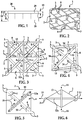
FIG. 1 is an illustration of a sectional view of a morphing panel structure which utilizes an embodiment of the adaptive structural core. -
FIG. 2 is an illustration of a perspective view, partially in section, of an embodiment of the adaptive structural core, with actuator attachment points provided in each of multiple core cells in the core. -
FIG. 3 is an illustration of a top view of a section of an embodiment of the adaptive structural core, more particularly illustrating an exemplary orientation of actuators, one of which is shown in solid lines and the other of which is shown in phantom lines, in each of multiple core cells of the adaptive structural core. -
FIG. 4 is an illustration of a top view of a core cell of an embodiment of the adaptive structural core, more particularly illustrating operation of the actuators in a cooperative manner to effect a change in shape of the core. -
FIG. 5 is an illustration of a top view of a core cell of an embodiment of the adaptive structural core, more particularly illustrating operation of the actuators in an antagonistic manner to effect stiffening of the core. -
FIG. 6 is an illustration of a schematic diagram which illustrates stress and strain imparted to each core cell of an embodiment of the adaptive structural core by the actuators in each core cell. -
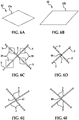
FIG. 6A is a diagram illustrating a rhombus geometry of a planar repeat structure of the adaptive structural core. -
FIG. 6B is a diagram illustrating a parallelogram geometry of a planar repeat structure of the adaptive structural core. -
FIG. 6C is an illustration of a top sectional view of a pair of core members arranged in a wine bottle case configuration. -
FIG. 6D is an illustration of a top sectional view of a pair of core members attached to each other in an interlocking configuration. -
FIG. 6E is an illustration of a top sectional view of a pair of core members adhered to each other. -
FIG. 6F is an illustration of a top sectional view of a pair of core members attached to each other via welding. -
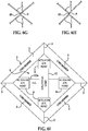
FIG. 6G is an illustration of a top sectional view of a pair of core members attached to each other via bonding. -
FIG. 6H is an illustration of a top sectional view of a pair of core members attached to each other via brazing. -
FIG. 6I is an illustration of a block diagram of a core cell of an embodiment of the adaptive structural core. -
FIG. 7 is an illustration of a schematic diagram which illustrates an actuator control system connected to an embodiment of the adaptive structural core. -
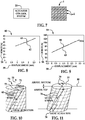
FIG. 8 is an illustration of a line graph which illustrates differential pressurization of a first actuator at 125 psi vs. pressurization of a second actuator at ∼10 psi, yielding a stiffness of 13.9 N/mm. -
FIG. 9 is an illustration of a line graph which illustrates differential pressurization of a first actuator at 125 psi vs. pressurization of a second actuator at 125 psi, yielding a stiffness of 19.4 N/mm. -
FIG. 10 is an illustration of a diagram which illustrates differential in-plane twisting deformation capability of an embodiment of a morphing panel structure of which the adaptive structural core is a part. -
FIG. 11 is an illustration of a diagram which illustrates differential in-plane shear deformation capability of an embodiment of a morphing panel structure of which the adaptive structural core is a part. -
FIG. 12 is an illustration of a perspective view of an exemplary aircraft with an aircraft skin which utilizes an embodiment of the adaptive structural core. -
FIG. 13 is an illustration of a contour plot of the effective semi-span torsional stiffness, GJ, as a function of effective aircraft skin elastic modulus and aircraft skin thickness. -
FIG. 14 is an illustration of a flow diagram of an embodiment of an adaptive structural core method. -
FIG. 14A is an illustration of a flow diagram of a method of adapting a structural core of a morphing panel structure. -
FIG. 15 is an illustration of a perspective view of a morphing panel structure. -
FIG. 16 is an illustration of a perspective view, partially in section, of an adaptive structural core which is suitable for the morphing panel structure shown inFIG. 15 . -
FIG. 17 is an illustration of a perspective view of the adaptive structural core with McKibben actuators provided in the core cells of the adaptive structural core shown inFIG. 16 . -
FIG. 18 is an illustration of a flow diagram of an aircraft production and service methodology. -
FIG. 19 is an illustration of a block diagram of an aircraft. - The following detailed description is merely exemplary in nature and is not intended to limit the described embodiments or the application and uses of the described embodiments. As used herein, the word "exemplary" or "illustrative" means "serving as an example, instance, or illustration." Any implementation described herein as "exemplary" or "illustrative" is not necessarily to be construed as preferred or advantageous over other implementations. All of the implementations described below are exemplary implementations provided to enable persons skilled in the art to practice the disclosure and are not intended to limit the scope of the appended claims. Furthermore, there is no intention to be bound by any expressed or implied theory presented in the preceding technical field, background, brief summary or the following detailed description.
- Referring initially to
FIGS. 1-7 , an illustrative embodiment of the adaptive structural core for morphing panel structures, hereinafter adaptive structural core, is generally indicated byreference numeral 1. As shown inFIG. 1 , in some applications the adaptivestructural core 1 may be part of a morphingpanel structure 28. As will be hereinafter described, the adaptivestructural core 1 may be adapted to impart stiffness or changes in shape to the morphingpanel structure 28. At least onecomposite facesheet 29 may be provided on the adaptivestructural core 1. In some embodiments, the adaptivestructural core 1 may be sandwiched between a pair of thecomposite facesheets 29, as shown inFIG. 1 . The morphingpanel structure 28 may be amenable to a variety of applications. In some applications, the morphingpanel structure 28 may be part of an aircraft wing skin 40 (FIG. 19 ) of anaircraft 94. The morphingpanel structure 28 may be amenable to other applications including but not limited to winglets, bay doors, resizable compartments, stabilizers, control surfaces and turbine inlet and outlet nozzles, as well as non-aerospace applications. - As shown in
FIGS. 2 and 3 , the adaptivestructural core 1 may includemultiple core members 3 which may be a metallic or composite material, for example and without limitation. In some embodiments, the adaptivestructural core 1 may be constructed in a web configuration in which thecore members 3 intersect at core member junctions 5 (FIG. 3 ). As shown inFIGS. 6A and 6B , the adaptivestructural core 1 may include a planarrepeat unit structure 42 in arhombus 42a (FIG. 6A ) orparallelogram 42b (FIG. 6b ) geometry.Multiple core cells 2, each having acell space 6, may be defined by and between the intersectingcore members 3. Thecore members 3 may havecore walls 4 which face thecore space 6 of eachcore cell 2. - The
core members 3 may be made with a series of stacked layers or even weaves or as a series of expanded strips that are bonded in narrow, periodic locations along the strips. As shown inFIG. 6C , in some embodiments, thecore members 3 may be constructed as a "wine case partition" 44 (vertically interleaved strips). Thecore members 3 may be interlocked 46 - (
FIG. 6D ), adhered 47 (FIG. 6E ), welded 48 (FIG. 6F ), bonded 49 (FIG. 6G ), brazed 50 (FIG. 6H ) and/or otherwise attached to each other. The adaptivestructural core 1 may be made as a monolith or in assemble-able portions from metal alloys or composite materials, for example and without limitation, via machining, laser cutting, water jet cutting, EDM or etching, for example and without limitation. Forcomposite core members 3, laser cutting or water jet cutting may be used to cut the strips or the core monolith. Various existing weave lay-ups and resin infiltration techniques may be used for making miniature core webs or assemble-able parts of the core structure. - As shown in
FIGS. 2 and6I , in some embodiments, actuator attachment points 8 may be provided in thecore members 3 to facilitate attachment ofactuators core members 3 to provide a mechanical connection between those components and the adaptivestructural core 1. In some embodiments, the actuator attachment points 8 may be openings provided in thecore members 3, as shown inFIG. 2 . In some embodiments, afirst actuator 12 may be oriented in a first diagonal orientation within thecell space 6 of eachcore cell 2. Asecond actuator 12a may be oriented in a second diagonal orientation within thecell space 6 of eachcore cell 2 in intersecting relationship with respect to thefirst actuator 12. In other embodiments, alternative orientations for theactuators - In some embodiments, the
actuators actuator actuators many core cells 2 in the adaptivestructural core 1. For example and without limitation, the actuator attachment points 8 (FIG. 2 ) may be holes or gaps made at the nodal locations or other locations along thecore members 3 without affecting the shear strength of the adaptivestructural core 1 for actuator insertion, sensors or electronic wiring. In some embodiments, McKibben actuators 12 may be assembled into actuator attachment points 8 at thecore nodes 5 such that a mechanical connection is made with the adaptivestructural core 1 but the tubing (not shown) of each actuator 12, 12a is continuous through the actuator attachment points 8 so that theactuator non-hydraulic actuators many core cells 2 in a single row (or actuator orientation), multiple rows or even continuous between rows and columns of the adaptive structural core 1 (both actuator orientations). This may enable remoting of fluidic valving (not shown) and distribution manifold (not shown). After installation of theactuators composite facesheets 29 may be attached to the adaptivestructural core 1 by bonding, welding, brazing and/or other attachment techniques to fabricate the morphing panel structure 28 (FIG. 1 ). - The
actuators composite facesheets 29 of the morphing panel structure 28 (FIG. 1 ). The strain sensors may feedback into control software of the actuator control system 20 (FIG. 7 ) and may be used to control the valve and pump hydraulic control actuators. - The
actuators core cells 2 of the adaptivestructural core 1 in such a manner as to optimize different performance values such as stiffness, displacement, mass, control authority energy, fabrication ease, etc. As shown inFIG. 7 , in some embodiments a remoteactuator control system 20 may be connected to each of theactuators FIG. 6 ). By designing the connectivity appropriately from theactuator control system 20 to the distributedactuators actuators actuators actuators core cell 2, a cooperative configuration can be realized to change the shape of thecore cells 2, as shown inFIG. 4 , in which the original shape of acore cell 2 is shown in phantom lines and the changed shape is shown in solid lines. Alternatively, theactuators core cells 2, as shown inFIG. 5 . When theactuators FIG. 4 , the shape of thecore cells 2 may remain the same while thecore members 3 of eachcore cell 2 may stiffen. - In
FIG. 6 , a schematic diagram which illustratesstress 14 andstrain 15 imparted to eachcore cell 2 of an illustrative embodiment of the adaptivestructural core 1 by theactuators core cell 2 is shown. Thecore cell 2 may be designed such that theactuators compliant direction structural core 1. When theactuators FIG. 4 , thedeformation mechanism core cells 2 and the adaptive structural core 1 (FIG. 3 ) to change shape. Conversely, when theactuators FIG. 5 , thedeformation mechanism actuators structural core 1. - Geometry definitions of the antagonistically-actuated core unit cell geometry with four static, compressive members (C4) forming a
rhombus 42a (FIG. 6A ) orparallelogram 42b (FIG. 6B ) and two tensile actuating members (T2) that diagonally cross the parallelogram may be expressed by equation (I), equation (II) and equation (II) below. In tensegrity nomenclature, this configuration is known as C4T2. Other tensegrity forms may be appropriate for planar actuation schemes. Equation (I) is a stress equation which represents the cross-sectional area normalized force generated by each actuator 12, 12a according to the actuator design variables. Equation (II) represents the kinematic strain in the 1-direction based on the core design variables.

- Based on Equation (I) and Equation (II) above, the strain and stress models of the
actuators core cells 2 can be used to compute the actuator and antagonistic configuration stiffness. For a given input δθ, P and δP, the resultant stress and strain which anactuator core cell 2 may be computed. When theactuator core cells 2, the kinematic relationship for thestrain 14 and thestress 15 generated by theactuator stress 14 to strain 15 when thecore cells 2 are subjected to an angular perturbation at different pressurization levels of theactuator 
- If no additional core stiffness losses occur, the effective modulus of the antagonistic actuation setup may be determined by the two
actuators actuators 
- The
core members 3 of thecore cells 2 may be tensioned with a pre-load. During cooperative actuation, contraction (and thus increased pressurization, +δP) of oneactuator second actuator actuators nodes 5 at which theactuators core members 3, increasing the existing actuator stiffness proportional to 2δP/P. - In some applications, the adaptive
structural core 1 may be a part of a morphing panel structure 28 (FIG. 1 ) which is used in the fabrication of aircraft skins on the wings and other surfaces of an aircraft. Theactuators core cells 2 of the adaptivestructural core 1 in such a manner as to reinforce a compliant direction (or mechanism) of the morphingpanel structure 28. Thus, when theactuators FIG. 4 , eachcore cell 2 and therefore the adaptivestructural core 1 may change shape, as indicated by the difference of thecore cell 2 shown in solid and phantom lines. This may induce the desired morphological changes in the aircraft wing or other surface of the aircraft before, after or during flight. When theactuators FIG. 5 , thedeformation mechanism actuators core members 3 and stiffening the adaptivestructural core 1 and the aircraft wing or other surface of the aircraft before, after or during flight. The morphingpanel structure 28 of which the adaptivestructural core 1 is a part may be used in conjunction with tailored substructures, actuation schemes, sensory feedback and a control system to reversibly and controllably morph the aircraft wing to the desired shape. In some applications, the morphingpanel structure 1 may be retained in the morphed configuration by locking theactuators actuators actuators structural core 1 may be amenable to a variety of other aerospace applications including but not limited to winglets, flaps, bay doors, seals, resizable compartments and turbine inlet and outlet nozzles, as well as non-aerospace applications. - The advantages of the adaptive
structural core 1 may address the needed stiffness for aerodynamic stability and low energy (and thus low actuation and power source mass) needed to control the structural displacement. Morphing aircraft may enhance flight control, endurance time and application versatility throughout the flight - The thickness 17 (
FIG. 1 ) of the adaptivestructural core 1 may be a substantial fraction of theoverall thickness 18 of the morphingpanel structure 28, and may be between one and ten times thesandwich panel facesheet 29thickness 19, typically between 0.02 inch and 4 inches. Embeddedactuators 12 may have a diameter or thickness 13 (FIG. 4 ) of between 0.01 inch and 1 inch and may have alength 13a (FIG. 5 ) short enough to fit inside eachcore cell 2. In some applications, the adaptivestructural core 1 may be 0.10 inch and theactuators diameter 13. For the morphing wing application, the mass and thickness of the aircraft skin may be a small fraction of the overall component (e.g. wing) thickness. The cell size and repeat unit distance of the core may be on the same order as the core thickness, with reasonable limitations on the thickness to achieve sufficient shape fidelity as noted herein above. -
FIGS. 8 and 9 illustrate a scaled-upunit cell 2 of the adaptivestructural core 1 withantagonistic actuators Δforce 58 /Δdisplacement 59).FIG. 8 is aline graph 60 which illustratesdifferential pressurization 61 of afirst actuator 12 at 125 psi vs.pressurization 62 of asecond actuator 12a at ∼10 psi, yielding a stiffness of 13.9 N/mm.FIG. 9 is aline graph 64 which illustratesdifferential pressurization 65 of afirst actuator 12 at 125 psi vs.pressurization 66 of asecond actuator 12a at 125 psi, yielding a stiffness of 19.4 N/mm. - Referring next to
FIGS. 10 and 11 , in-plane deformation capabilities of the morphingpanel structure 28 in implementation of an illustrative embodiment of theadaptive structure core 1 are shown.FIG. 10 illustrates differential in-plane global twistingdeformation capability 68 of the morphingpanel structure 28. With the compliant axes of thestructure 28 oriented at a positive (counterclockwise) 71 and a negative (clockwise) 72 angle with respect to thespan axis 70, the reversible shear deformation design may permit wing twisting in aclosed airfoil geometry 73 by differential deformation of thecounterclockwise angle 71 with respect to theclockwise angle 72 around the entireclosed geometry 73. This change in shape permits aresultant twist 68 about thespan axis 70 as shown inFIG. 10. FIG. 11 illustrates differential in-planeshear deformation capability 76 of thestructure 28. When thedifferential deformation 76 occurs symmetrically between the top 77 and bottom 78 of thestructure 28, asweep change 79 and a corresponding fractional change in chord and span may occur. Aspect ratio (chord/camber change or area change) in planform may be accomplished with theshearing deformation design 76 by having the differential deformation described above be mirror symmetric with respect to thearea change plane 80. - Referring next to
FIGS. 12 and 13 , in some applications the adaptivestructural core 1 may be utilized in thewing skin 25 of anaircraft 24.FIG. 13 is acontour plot 82 of the effective semi-span torsional stiffness, GJ, (reference numeral 83 inFIG. 13 ) as a function of effective skin modulus andskin thickness 84 of thewing skin 25 which utilizes the adaptivestructural core 1 inFIG. 12 . The study application requirement is 594 Pa-m4. By combining the twisting characteristics of thesandwich panel structure 85 of theaircraft skin 25 withantagonistic actuation 86 in the adaptivestructural core 1, thetorsional stiffness 83 in thewing skin 25 may be met. - The adaptive
structural core 1 may be fabricated by assembling thecore members 3 into a rhombusgeometry core cell 2 with twoactuators core cell 2. With an attached fluidic distribution manifold (not shown), theactuators actuators core members 3, increasing the strength and stiffness of the adaptivestructural core 1. This form of antagonistic operation may cinch the rhombus-shaped repeatunit core cell 2. Sensors (not shown) may be required to validate the shear deformation, cinching operations and to provide a feedback signal for a software control system. - Two different actuator control signal circuits may be connected to the
core members 3 such that, when activated, thecore cell 2 is statically indeterminant (there is a state of self-stress in all the core members 3). The control signal may be provided via electrical or fluidic conduits such as manifolds and valving or electronic flex circuitry bonded to thecore members 3. Sensors may be pressure sensors, load cells, displacement or angle sensors or linear or angular potentiometers. - Referring next to
FIG. 14 , a flow diagram 1400 of an illustrative embodiment of an adaptive structural core method is shown. In FIG. 1402,core members 3 are provided. Inblock 1404, an adaptivestructural core 1 is formed by arranging thecore members 3 in a repeating pattern. Inblock 1406, actuator attachment points 8 are provided on thecore members 3. Inblock 1408, actuators 12, 12a are provided. Inblock 1410, theactuators core members 3. Inblock 1412, at least onecomposite facesheet 29 is provided on the adaptivestructural core 1. Inblock 1414, in some applications the shape of thecore 1 may be changed by operating theactuators 12 in acooperative manner 54. Inblock 1416, in some applications thecore 1 may be stiffened by operating theactuators antagonistic manner 55. In some aerospace applications, an aircraft operator may choose a morphing shape for the wing skin 25 (FIG. 12 ) which utilizes thecore 1. The aircraft operator may operate theactuators core cell 2 of thecore 1 to change the shape of eachcore cell 2, as was heretofore described with respect toFIG. 4 . Thecore 1 may change or morph the shape of thewing skin 25. Provision may be made for the aircraft operator to confirm whether the selected shape for thewing skin 25 conforms to the shape which was selected by the aircraft operator. - Referring next to
FIG. 14A , a flow diagram 1400a which illustrates a method of adapting a structural core of a morphing panel structure is shown. Inblock 1402a, an adaptivestructural core 1 havingintersecting core members 3 andcore cells 2 defined by thecore members 3 may be provided. Inblock 1404a, at least oneactuator core cell 2. In some embodiments, a pair ofactuators core cell 2. Inblock 1406a, theactuators core members 3. Inblock 1408a, thestructural core 1 may be adapted byactuation actuators actuators antagonistic manner 55 to stiffen thecore cells 2. Theactuators cooperative manner 54 to change the shape of thecore cells 2. - Referring next to
FIGS. 15-17 , an illustrative morphingpanel structure 31 is shown inFIG. 15 . The morphingpanel structure 31 may include an adaptivestructural core 34 which is shown inFIG. 16 . The adaptivestructural core 34 may include a network of intersectingcore members 35 defining multiple rows and columns ofcore cells 36. The adaptivestructural core 34 may be mounted in acore frame 32 which may be fitted withframe mount openings 33 to facilitate attachment of thecore frame 32 to a structure (not shown) using bolts or other fasteners (not shown). Two sets of McKibben actuators 37 may extend diagonally through eachcore cell 36 of the adaptivestructural core 34 in intersecting relationship with respect to each other. In some embodiments, each McKibben actuator 37 may be continuous acrossmultiple core cells 36, as shown inFIG. 17 . As shown inFIG. 15 , acomposite facesheet 38 may be provided on at least one surface of the adaptivestructural core 34. In some embodiments, the adaptivestructural core 34 may be sandwiched between a pair ofcomposite facesheets 38 provided on opposite surfaces of the adaptivestructural core 34. - Referring next to
FIGS. 18 and 19 , embodiments of the disclosure may be used in the context of an aircraft manufacturing andservice method 78 as shown inFIG. 18 and anaircraft 94 as shown inFIG. 19 . During pre-production,exemplary method 78 may include specification anddesign 80 of theaircraft 94 andmaterial procurement 82. During production, component andsubassembly manufacturing 84 andsystem integration 86 of theaircraft 94 takes place. Thereafter, theaircraft 94 may go through certification anddelivery 88 in order to be placed inservice 90. While in service by a customer, theaircraft 94 may be scheduled for routine maintenance and service 92 (which may also include modification, reconfiguration, refurbishment, and so on). - Each of the processes of
method 78 may be performed or carried out by a system integrator, a third party, and/or an operator (e.g., a customer). For the purposes of this description, a system integrator may include without limitation any number of aircraft manufacturers and major-system subcontractors; a third party may include without limitation any number of vendors, subcontractors, and suppliers; and an operator may be an airline, leasing company, military entity, service organization, and so on. - As shown in
FIG. 19 , theaircraft 94 produced byexemplary method 78 may include anairframe 98 with a plurality ofsystems 96 and an interior 100. Examples of high-level systems 96 include one or more of apropulsion system 102, anelectrical system 104, ahydraulic system 106, and anenvironmental system 108. Any number of other systems may be included. Although an aerospace example is shown, the principles of the invention may be applied to other industries, such as the automotive industry. Awing skin 40 may be provided on theairframe 98. At least one morphingpanel structure 28 may be incorporated into thewing skin 40. - The apparatus embodied herein may be employed during any one or more of the stages of the production and
service method 78. For example, components or subassemblies corresponding toproduction process 84 may be fabricated or manufactured in a manner similar to components or subassemblies produced while theaircraft 94 is in service. Also one or more apparatus embodiments may be utilized during the production stages 84 and 86, for example, by substantially expediting assembly of or reducing the cost of anaircraft 94. Similarly, one or more apparatus embodiments may be utilized while theaircraft 94 is in service, for example and without limitation, to maintenance andservice 92. - Although the embodiments of this disclosure have been described with respect to certain exemplary embodiments, it is to be understood that the specific embodiments are for purposes of illustration and not limitation, as other variations will occur to those of skill in the art.
-
- Clause A1. An adaptive structural core for morphing panel structures, comprising:
- a plurality of core members arranged in a repeating pattern;
- a plurality of actuator attachment points provided on said plurality of core members; and
- at least one actuator engaging said plurality of actuator attachment points.
- Clause A2. The adaptive structural core of clause A1 wherein said plurality of core members are arranged in a planar repeat pattern.
- Clause A3. The adaptive structural core of clause A2 wherein said repeating pattern comprises a rhombus pattern. Clause A4. The adaptive structural core of clause A2 wherein said repeating pattern comprises a parallelogram pattern.
- Clause A5. The adaptive structural core of clause A1 wherein said plurality of core members define a plurality of core cells each having a plurality of cell walls.
- Clause A6. The adaptive structural core of clause A5 wherein said plurality of actuator attachment points comprises a pair of actuator attachment points provided on opposing ones of said plurality of cell walls of each of said core cells.
- Clause A7. The adaptive structural core of clause A6 wherein each of said plurality of actuator attachment points comprises an actuator attachment opening.
- Clause A8. The adaptive structural core of clause A5 further comprising a plurality of actuators attached to opposing ones of said plurality of cell walls of each of said plurality of core cells.
- Clause A9. The adaptive structural core of clause A8 wherein each of said plurality of actuators is configured to exert forces on said cell walls in a cooperative manner. Clause A10. The adaptive structural core of clause A8 wherein each of said plurality of actuators is configured to exert forces on said cell walls in an antagonistic manner. Clause A11. The adaptive structural core of clause A1 wherein said plurality of core members comprises a plurality of metal core members or composite core members.
- Clause B1. An adaptive structural core method, comprising:
- providing a plurality of core members;
- arranging said plurality of core members in a repeating pattern; and
- providing a plurality of actuator attachment points on said plurality of core members.
- Clause B2. The method of clause B1 wherein said arranging said plurality of core members in a repeating pattern comprises arranging said plurality of core members into a plurality of core cells having a plurality of cell walls and wherein said providing a plurality of actuator attachment points on said plurality of core members comprises providing attachment points on opposing ones of said plurality of cell walls, respectively.
- Clause B3. The method of clause B2 further comprising providing a pair of actuators in each of said plurality of core cells and attaching said pair of actuators to said attachment points, respectively.
- Clause B4. The method of clause B1 further comprising at least one composite facesheet on said plurality of core members.
Claims (15)
- An adaptive structural core (1) for morphing panel structures, comprising:a plurality of core members (3), arranged in a repeating pattern;a plurality of actuator attachment points (8) provided on said plurality of core members, wherein the actuator attachment points are holes or gaps; andat least one actuator (12, 12a) engaging said plurality of actuator attachment points (8).
- The adaptive structural core of claim 1, wherein said plurality of core members is arranged in a planar repeat pattern.
- The adaptive structural core of claim 2, wherein said repeating pattern comprises a rhombus pattern.
- The adaptive structural core of claim 2, wherein said repeating pattern comprises a parallelogram pattern.
- The adaptive structural core of claim 1, wherein said plurality of core members defines a plurality of core cells, each having a plurality of cell walls.
- The adaptive structural core of claim 5, wherein said plurality of actuator attachment points comprises a pair of actuator attachment points, provided on opposing ones of said plurality of cell walls of each of said core cells.
- The adaptive structural core of claim 5, further comprising a plurality of actuators, attached to opposing ones of said plurality of cell walls of each of said plurality of core cells.
- The adaptive structural core of claim 7, wherein each of said plurality of actuators is configured to exert forces on said cell walls in a cooperative manner.
- The adaptive structural core of claim 7, wherein each of said plurality of actuators is configured to exert forces on said cell walls in an antagonistic manner.
- The adaptive structural core of claim 5, wherein the at least one actuator (12, 12a) is a McKibben actuator, assembled into actuator attachment points (8) at core nodes (5) such that a mechanical connection is made with the adaptive structural core (1), and tubing of each actuator (12, 12a) is continuous through the actuator attachment points (8).
- The adaptive structural core of claim 10 wherein the at least one McKibben actuator is a pneumatic or hydraulic McKibben actuator, configured to be fluidically continuous along many core cells (2) in a single row, in multiple rows, between rows and columns of the adaptive structural core (1), in an actuator orientation or in both actuator orientations.
- The adaptive structural core of claim 5 wherein the at least one actuator (12, 12a) is a non-hydraulic actuator, configured to be fluidically continuous along many core cells (2) in a single row, in multiple rows, between rows and columns of the adaptive structural core (1), in an actuator orientation, or in both actuator orientations.
- An adaptive structural core method, comprising:providing a plurality of core members;arranging said plurality of core members in a repeating pattern; andproviding a plurality of actuator attachment points on said plurality of core members, wherein the actuator attachment points are holes or gaps.
- The method of claim 13 wherein
said arranging said plurality of core members in a repeating pattern comprises arranging said plurality of core members into a plurality of core cells having a plurality of cell walls; and
wherein said providing a plurality of actuator attachment points on said plurality of core members comprises providing attachment points on opposing ones of said plurality of cell walls, respectively. - The method of claim 14 further comprising providing a pair of actuators in each of said plurality of core cells and attaching said pair of actuators to said attachment points, respectively.
Applications Claiming Priority (4)
| Application Number | Priority Date | Filing Date | Title |
|---|---|---|---|
| US26095009P | 2009-11-13 | 2009-11-13 | |
| US12/699,285 US8746626B1 (en) | 2009-11-13 | 2010-02-03 | Adaptive structural core for morphing panel structures |
| PCT/US2010/049837 WO2011059571A1 (en) | 2009-11-13 | 2010-09-22 | Adaptive structural core for morphing panel structures |
| EP10760551.1A EP2470422B1 (en) | 2009-11-13 | 2010-09-22 | Adaptive structural core for morphing panel structures |
Related Parent Applications (2)
| Application Number | Title | Priority Date | Filing Date |
|---|---|---|---|
| EP10760551.1A Division EP2470422B1 (en) | 2009-11-13 | 2010-09-22 | Adaptive structural core for morphing panel structures |
| EP10760551.1A Division-Into EP2470422B1 (en) | 2009-11-13 | 2010-09-22 | Adaptive structural core for morphing panel structures |
Publications (2)
| Publication Number | Publication Date |
|---|---|
| EP3441304A1 true EP3441304A1 (en) | 2019-02-13 |
| EP3441304B1 EP3441304B1 (en) | 2021-11-03 |
Family
ID=43066688
Family Applications (2)
| Application Number | Title | Priority Date | Filing Date |
|---|---|---|---|
| EP10760551.1A Active EP2470422B1 (en) | 2009-11-13 | 2010-09-22 | Adaptive structural core for morphing panel structures |
| EP18195227.6A Active EP3441304B1 (en) | 2009-11-13 | 2010-09-22 | Adaptive structural core for morphing panel structures |
Family Applications Before (1)
| Application Number | Title | Priority Date | Filing Date |
|---|---|---|---|
| EP10760551.1A Active EP2470422B1 (en) | 2009-11-13 | 2010-09-22 | Adaptive structural core for morphing panel structures |
Country Status (6)
| Country | Link |
|---|---|
| US (1) | US8746626B1 (en) |
| EP (2) | EP2470422B1 (en) |
| JP (2) | JP6181928B2 (en) |
| CN (1) | CN102686478B (en) |
| ES (1) | ES2709752T3 (en) |
| WO (1) | WO2011059571A1 (en) |
Families Citing this family (17)
| Publication number | Priority date | Publication date | Assignee | Title |
|---|---|---|---|---|
| US12260396B2 (en) | 2010-01-08 | 2025-03-25 | Blackhawk Network, Inc. | System for payment via electronic wallet |
| US8746626B1 (en) | 2009-11-13 | 2014-06-10 | The Boeing Company | Adaptive structural core for morphing panel structures |
| GB201207525D0 (en) | 2012-04-30 | 2012-06-13 | Airbus Operations Ltd | Morphing aerofoil |
| CN104487342B (en) * | 2012-06-21 | 2017-02-22 | 庞巴迪公司 | Morphing wing for an aircraft |
| US8991769B2 (en) * | 2013-01-28 | 2015-03-31 | Toyota Motor Engineering & Manufacturing North America, Inc. | Two-dimensional morphing structure for wing |
| CA2961872A1 (en) | 2014-09-25 | 2016-03-31 | Bombardier Inc. | Morphing skin for an aircraft |
| US9783978B1 (en) | 2016-08-01 | 2017-10-10 | University Of South Florida | Shape-morphing space frame apparatus using linear bistable elements |
| WO2017087036A1 (en) | 2015-11-20 | 2017-05-26 | University Of South Florida | Shape-morphing space frame apparatus using unit cell bistable elements |
| CN106569441B (en) * | 2016-10-25 | 2019-01-29 | 南京航空航天大学 | A distributed drive integral tension deformable wing device and control method |
| ES2763549T3 (en) * | 2016-12-21 | 2020-05-29 | Airbus Operations Sl | Aircraft with a variable fuselage surface for optimization of the boundary layer |
| CN106827991B (en) * | 2017-02-10 | 2019-09-13 | 哈尔滨工业大学 | Bistable wing of a water-air amphibious vehicle |
| CN106585948B (en) * | 2017-02-10 | 2019-10-29 | 哈尔滨工业大学 | A kind of empty amphibious unmanned vehicle of water |
| CN108116657A (en) * | 2017-11-27 | 2018-06-05 | 西北工业大学 | A kind of wing damper mechanism based on shape memory spring distressed structure |
| CN109572988B (en) * | 2018-12-28 | 2020-09-15 | 湖北航天技术研究院总体设计所 | Deformation aircraft cabin section structure |
| EP4353970B1 (en) * | 2022-10-12 | 2025-11-26 | Audi AG | Drive unit as well as actuator comprising a shape memory wire swung several times around a four-joint |
| GB2628776B (en) * | 2023-04-03 | 2026-03-11 | Isaksen Guttorm | Shape changing maneuvering system |
| CN117682045B (en) * | 2023-12-25 | 2024-08-06 | 北京理工大学 | Distributed driving active deformation aircraft skin structure and deformation method thereof |
Citations (4)
| Publication number | Priority date | Publication date | Assignee | Title |
|---|---|---|---|---|
| DE19709917C1 (en) * | 1997-03-11 | 1998-04-23 | Daimler Benz Ag | Device for controlled deformation of shell structure, e.g. aircraft support surface |
| DE102004063093A1 (en) * | 2004-12-22 | 2006-07-20 | Airbus Deutschland Gmbh | Spar box for forming e.g. aerodynamic wing of aircraft, has positioning units changing surface geometry of aerodynamic active surface and/or mechanical characteristic of box depending upon load conditions, using control and regulating unit |
| US20080035788A1 (en) * | 2006-08-11 | 2008-02-14 | Techno-Sciences, Inc. | Cellular support structures used for controlled actuation of fluid contact surfaces |
| US20080035798A1 (en) * | 2006-08-11 | 2008-02-14 | Techno-Sciences, Inc. | Fluid-driven artificial muscles as mechanisms for controlled actuation |
Family Cites Families (12)
| Publication number | Priority date | Publication date | Assignee | Title |
|---|---|---|---|---|
| US3118639A (en) * | 1961-12-05 | 1964-01-21 | California Inst Res Found | Control and propulsion fluid foil |
| DE69425654T2 (en) * | 1993-05-06 | 2000-12-28 | Northrop Grumman Corp., Los Angeles | DEVICE AND METHOD FOR CHANGING THE FORM OF A STRUCTURE |
| US5662294A (en) | 1994-02-28 | 1997-09-02 | Lockheed Martin Corporation | Adaptive control surface using antagonistic shape memory alloy tendons |
| US6447871B1 (en) | 1999-09-27 | 2002-09-10 | The Aerospace Corporation | Composite materials with embedded machines |
| US7598651B2 (en) | 2004-03-12 | 2009-10-06 | Sri International | Mechanical meta-materials |
| US20070138341A1 (en) | 2004-12-07 | 2007-06-21 | Joshi Shiv P | Transformable skin |
| US20060145030A1 (en) * | 2004-12-07 | 2006-07-06 | Cowan David L | Deformation-control system and method |
| US20060118675A1 (en) | 2004-12-07 | 2006-06-08 | Tidwell John Z | Transformable fluid foil with pivoting spars and ribs |
| DE502005001475D1 (en) * | 2004-12-22 | 2007-10-25 | Airbus Deutschland Gmbh Hrb 43527 | Structure of an aerodynamic effective surface of an aircraft |
| US7901524B1 (en) * | 2005-02-04 | 2011-03-08 | Hrl Laboratories, Llc | Actuation concepts for variable stiffness materials |
| CN102196989A (en) | 2008-10-29 | 2011-09-21 | Nxp股份有限公司 | An integrated component and a method of manufacturing an integrated component |
| US8746626B1 (en) | 2009-11-13 | 2014-06-10 | The Boeing Company | Adaptive structural core for morphing panel structures |
-
2010
- 2010-02-03 US US12/699,285 patent/US8746626B1/en active Active
- 2010-09-22 EP EP10760551.1A patent/EP2470422B1/en active Active
- 2010-09-22 WO PCT/US2010/049837 patent/WO2011059571A1/en not_active Ceased
- 2010-09-22 ES ES10760551T patent/ES2709752T3/en active Active
- 2010-09-22 EP EP18195227.6A patent/EP3441304B1/en active Active
- 2010-09-22 CN CN201080048356.2A patent/CN102686478B/en active Active
- 2010-09-22 JP JP2012538816A patent/JP6181928B2/en active Active
-
2016
- 2016-03-15 JP JP2016050595A patent/JP6267255B2/en active Active
Patent Citations (4)
| Publication number | Priority date | Publication date | Assignee | Title |
|---|---|---|---|---|
| DE19709917C1 (en) * | 1997-03-11 | 1998-04-23 | Daimler Benz Ag | Device for controlled deformation of shell structure, e.g. aircraft support surface |
| DE102004063093A1 (en) * | 2004-12-22 | 2006-07-20 | Airbus Deutschland Gmbh | Spar box for forming e.g. aerodynamic wing of aircraft, has positioning units changing surface geometry of aerodynamic active surface and/or mechanical characteristic of box depending upon load conditions, using control and regulating unit |
| US20080035788A1 (en) * | 2006-08-11 | 2008-02-14 | Techno-Sciences, Inc. | Cellular support structures used for controlled actuation of fluid contact surfaces |
| US20080035798A1 (en) * | 2006-08-11 | 2008-02-14 | Techno-Sciences, Inc. | Fluid-driven artificial muscles as mechanisms for controlled actuation |
Also Published As
| Publication number | Publication date |
|---|---|
| JP6267255B2 (en) | 2018-01-24 |
| JP6181928B2 (en) | 2017-08-16 |
| WO2011059571A1 (en) | 2011-05-19 |
| ES2709752T3 (en) | 2019-04-17 |
| CN102686478B (en) | 2015-08-19 |
| CN102686478A (en) | 2012-09-19 |
| US8746626B1 (en) | 2014-06-10 |
| EP3441304B1 (en) | 2021-11-03 |
| JP2016155546A (en) | 2016-09-01 |
| EP2470422A1 (en) | 2012-07-04 |
| EP2470422B1 (en) | 2018-11-07 |
| JP2013510763A (en) | 2013-03-28 |
Similar Documents
| Publication | Publication Date | Title |
|---|---|---|
| US8746626B1 (en) | Adaptive structural core for morphing panel structures | |
| US8703268B2 (en) | Morphing panel structure | |
| Vasista et al. | Realization of morphing wings: a multidisciplinary challenge | |
| Lachenal et al. | Review of morphing concepts and materials for wind turbine blade applications | |
| US12103676B2 (en) | Elastic shape morphing of ultra-light structures by programmable assembly | |
| Scott et al. | Controlling panel flutter using adaptive materials | |
| US12296948B2 (en) | Variable morphing wing using surface actuated origami folds | |
| Daynes et al. | Concept for morphing airfoil with zero torsional stiffness | |
| Vasista et al. | Structural and systems modelling of a fluid-driven morphing winglet trailing edge | |
| Kimaru et al. | Design, manufacture and test of a camber morphing wing using MFC actuated mart rib | |
| Vasista et al. | Pressure-driven morphing devices for 3D shape changes with multiple degrees-of-freedom | |
| Bae et al. | Aeroelastic considerations on shape control of an adaptive wing | |
| Saxena et al. | Shape morphing metamaterials via pressure actuated shape morphing cells | |
| Wright et al. | A piezocomposite trailing-edge for subsonic aircraft | |
| Boston et al. | Monolithic morphing rib with selective stiffness from embeddable bi-stable elements | |
| Weisshaar | Aeroservoelastic control concepts with active materials | |
| EP4594178A1 (en) | A control unit, a force actuation element and a method for adjusting an element of an aircraft | |
| Machunze et al. | Active flow control system integration into a CFRP flap | |
| Vasista et al. | Design and Manufacture of a Fluid-Actuated Morphing Winglet Trailing Edge Control Surface | |
| Zhou | Distributed actuation and control of smart structures | |
| Bilgen et al. | Wing morphing design using macro-fiber composites | |
| Miglioretti | ECOLE DOCTORALE 139 CONNAISSANCE, LANGAGE, MODELISATION Doctorat en Sciences pour l’Ingénieur Spécialité Mécanique | |
| Deshpande | At the Intersection of Bistability and Elastic Instability: Switching and Locking Structures using Asymmetric Carbon Fiber Composites | |
| Murray | Structural and aerodynamic considerations of an active piezoelectric trailing-edge tab on a helicopter rotor | |
| Sathyamoorthy et al. | Piezoelectric Based Adaptive Wing for Flow Control |
Legal Events
| Date | Code | Title | Description |
|---|---|---|---|
| PUAI | Public reference made under article 153(3) epc to a published international application that has entered the european phase |
Free format text: ORIGINAL CODE: 0009012 |
|
| STAA | Information on the status of an ep patent application or granted ep patent |
Free format text: STATUS: REQUEST FOR EXAMINATION WAS MADE |
|
| 17P | Request for examination filed |
Effective date: 20180918 |
|
| AC | Divisional application: reference to earlier application |
Ref document number: 2470422 Country of ref document: EP Kind code of ref document: P |
|
| AK | Designated contracting states |
Kind code of ref document: A1 Designated state(s): AL AT BE BG CH CY CZ DE DK EE ES FI FR GB GR HR HU IE IS IT LI LT LU LV MC MK MT NL NO PL PT RO SE SI SK SM TR |
|
| GRAP | Despatch of communication of intention to grant a patent |
Free format text: ORIGINAL CODE: EPIDOSNIGR1 |
|
| STAA | Information on the status of an ep patent application or granted ep patent |
Free format text: STATUS: GRANT OF PATENT IS INTENDED |
|
| INTG | Intention to grant announced |
Effective date: 20201125 |
|
| GRAJ | Information related to disapproval of communication of intention to grant by the applicant or resumption of examination proceedings by the epo deleted |
Free format text: ORIGINAL CODE: EPIDOSDIGR1 |
|
| STAA | Information on the status of an ep patent application or granted ep patent |
Free format text: STATUS: REQUEST FOR EXAMINATION WAS MADE |
|
| INTC | Intention to grant announced (deleted) | ||
| GRAP | Despatch of communication of intention to grant a patent |
Free format text: ORIGINAL CODE: EPIDOSNIGR1 |
|
| STAA | Information on the status of an ep patent application or granted ep patent |
Free format text: STATUS: GRANT OF PATENT IS INTENDED |
|
| INTG | Intention to grant announced |
Effective date: 20210520 |
|
| GRAS | Grant fee paid |
Free format text: ORIGINAL CODE: EPIDOSNIGR3 |
|
| GRAA | (expected) grant |
Free format text: ORIGINAL CODE: 0009210 |
|
| STAA | Information on the status of an ep patent application or granted ep patent |
Free format text: STATUS: THE PATENT HAS BEEN GRANTED |
|
| AC | Divisional application: reference to earlier application |
Ref document number: 2470422 Country of ref document: EP Kind code of ref document: P |
|
| AK | Designated contracting states |
Kind code of ref document: B1 Designated state(s): AL AT BE BG CH CY CZ DE DK EE ES FI FR GB GR HR HU IE IS IT LI LT LU LV MC MK MT NL NO PL PT RO SE SI SK SM TR |
|
| REG | Reference to a national code |
Ref country code: GB Ref legal event code: FG4D |
|
| REG | Reference to a national code |
Ref country code: AT Ref legal event code: REF Ref document number: 1443744 Country of ref document: AT Kind code of ref document: T Effective date: 20211115 Ref country code: CH Ref legal event code: EP |
|
| REG | Reference to a national code |
Ref country code: DE Ref legal event code: R096 Ref document number: 602010067783 Country of ref document: DE |
|
| REG | Reference to a national code |
Ref country code: IE Ref legal event code: FG4D |
|
| REG | Reference to a national code |
Ref country code: LT Ref legal event code: MG9D |
|
| REG | Reference to a national code |
Ref country code: NL Ref legal event code: MP Effective date: 20211103 |
|
| REG | Reference to a national code |
Ref country code: AT Ref legal event code: MK05 Ref document number: 1443744 Country of ref document: AT Kind code of ref document: T Effective date: 20211103 |
|
| PG25 | Lapsed in a contracting state [announced via postgrant information from national office to epo] |
Ref country code: LT Free format text: LAPSE BECAUSE OF FAILURE TO SUBMIT A TRANSLATION OF THE DESCRIPTION OR TO PAY THE FEE WITHIN THE PRESCRIBED TIME-LIMIT Effective date: 20211103 Ref country code: FI Free format text: LAPSE BECAUSE OF FAILURE TO SUBMIT A TRANSLATION OF THE DESCRIPTION OR TO PAY THE FEE WITHIN THE PRESCRIBED TIME-LIMIT Effective date: 20211103 Ref country code: BG Free format text: LAPSE BECAUSE OF FAILURE TO SUBMIT A TRANSLATION OF THE DESCRIPTION OR TO PAY THE FEE WITHIN THE PRESCRIBED TIME-LIMIT Effective date: 20220203 Ref country code: AT Free format text: LAPSE BECAUSE OF FAILURE TO SUBMIT A TRANSLATION OF THE DESCRIPTION OR TO PAY THE FEE WITHIN THE PRESCRIBED TIME-LIMIT Effective date: 20211103 |
|
| PG25 | Lapsed in a contracting state [announced via postgrant information from national office to epo] |
Ref country code: IS Free format text: LAPSE BECAUSE OF FAILURE TO SUBMIT A TRANSLATION OF THE DESCRIPTION OR TO PAY THE FEE WITHIN THE PRESCRIBED TIME-LIMIT Effective date: 20220303 Ref country code: SE Free format text: LAPSE BECAUSE OF FAILURE TO SUBMIT A TRANSLATION OF THE DESCRIPTION OR TO PAY THE FEE WITHIN THE PRESCRIBED TIME-LIMIT Effective date: 20211103 Ref country code: PT Free format text: LAPSE BECAUSE OF FAILURE TO SUBMIT A TRANSLATION OF THE DESCRIPTION OR TO PAY THE FEE WITHIN THE PRESCRIBED TIME-LIMIT Effective date: 20220303 Ref country code: PL Free format text: LAPSE BECAUSE OF FAILURE TO SUBMIT A TRANSLATION OF THE DESCRIPTION OR TO PAY THE FEE WITHIN THE PRESCRIBED TIME-LIMIT Effective date: 20211103 Ref country code: NO Free format text: LAPSE BECAUSE OF FAILURE TO SUBMIT A TRANSLATION OF THE DESCRIPTION OR TO PAY THE FEE WITHIN THE PRESCRIBED TIME-LIMIT Effective date: 20220203 Ref country code: NL Free format text: LAPSE BECAUSE OF FAILURE TO SUBMIT A TRANSLATION OF THE DESCRIPTION OR TO PAY THE FEE WITHIN THE PRESCRIBED TIME-LIMIT Effective date: 20211103 Ref country code: LV Free format text: LAPSE BECAUSE OF FAILURE TO SUBMIT A TRANSLATION OF THE DESCRIPTION OR TO PAY THE FEE WITHIN THE PRESCRIBED TIME-LIMIT Effective date: 20211103 Ref country code: HR Free format text: LAPSE BECAUSE OF FAILURE TO SUBMIT A TRANSLATION OF THE DESCRIPTION OR TO PAY THE FEE WITHIN THE PRESCRIBED TIME-LIMIT Effective date: 20211103 Ref country code: GR Free format text: LAPSE BECAUSE OF FAILURE TO SUBMIT A TRANSLATION OF THE DESCRIPTION OR TO PAY THE FEE WITHIN THE PRESCRIBED TIME-LIMIT Effective date: 20220204 Ref country code: ES Free format text: LAPSE BECAUSE OF FAILURE TO SUBMIT A TRANSLATION OF THE DESCRIPTION OR TO PAY THE FEE WITHIN THE PRESCRIBED TIME-LIMIT Effective date: 20211103 |
|
| PG25 | Lapsed in a contracting state [announced via postgrant information from national office to epo] |
Ref country code: SM Free format text: LAPSE BECAUSE OF FAILURE TO SUBMIT A TRANSLATION OF THE DESCRIPTION OR TO PAY THE FEE WITHIN THE PRESCRIBED TIME-LIMIT Effective date: 20211103 Ref country code: SK Free format text: LAPSE BECAUSE OF FAILURE TO SUBMIT A TRANSLATION OF THE DESCRIPTION OR TO PAY THE FEE WITHIN THE PRESCRIBED TIME-LIMIT Effective date: 20211103 Ref country code: RO Free format text: LAPSE BECAUSE OF FAILURE TO SUBMIT A TRANSLATION OF THE DESCRIPTION OR TO PAY THE FEE WITHIN THE PRESCRIBED TIME-LIMIT Effective date: 20211103 Ref country code: EE Free format text: LAPSE BECAUSE OF FAILURE TO SUBMIT A TRANSLATION OF THE DESCRIPTION OR TO PAY THE FEE WITHIN THE PRESCRIBED TIME-LIMIT Effective date: 20211103 Ref country code: DK Free format text: LAPSE BECAUSE OF FAILURE TO SUBMIT A TRANSLATION OF THE DESCRIPTION OR TO PAY THE FEE WITHIN THE PRESCRIBED TIME-LIMIT Effective date: 20211103 Ref country code: CZ Free format text: LAPSE BECAUSE OF FAILURE TO SUBMIT A TRANSLATION OF THE DESCRIPTION OR TO PAY THE FEE WITHIN THE PRESCRIBED TIME-LIMIT Effective date: 20211103 |
|
| REG | Reference to a national code |
Ref country code: DE Ref legal event code: R097 Ref document number: 602010067783 Country of ref document: DE |
|
| PLBE | No opposition filed within time limit |
Free format text: ORIGINAL CODE: 0009261 |
|
| STAA | Information on the status of an ep patent application or granted ep patent |
Free format text: STATUS: NO OPPOSITION FILED WITHIN TIME LIMIT |
|
| 26N | No opposition filed |
Effective date: 20220804 |
|
| PG25 | Lapsed in a contracting state [announced via postgrant information from national office to epo] |
Ref country code: AL Free format text: LAPSE BECAUSE OF FAILURE TO SUBMIT A TRANSLATION OF THE DESCRIPTION OR TO PAY THE FEE WITHIN THE PRESCRIBED TIME-LIMIT Effective date: 20211103 |
|
| PG25 | Lapsed in a contracting state [announced via postgrant information from national office to epo] |
Ref country code: SI Free format text: LAPSE BECAUSE OF FAILURE TO SUBMIT A TRANSLATION OF THE DESCRIPTION OR TO PAY THE FEE WITHIN THE PRESCRIBED TIME-LIMIT Effective date: 20211103 |
|
| PG25 | Lapsed in a contracting state [announced via postgrant information from national office to epo] |
Ref country code: MC Free format text: LAPSE BECAUSE OF FAILURE TO SUBMIT A TRANSLATION OF THE DESCRIPTION OR TO PAY THE FEE WITHIN THE PRESCRIBED TIME-LIMIT Effective date: 20211103 |
|
| REG | Reference to a national code |
Ref country code: CH Ref legal event code: PL |
|
| REG | Reference to a national code |
Ref country code: BE Ref legal event code: MM Effective date: 20220930 |
|
| PG25 | Lapsed in a contracting state [announced via postgrant information from national office to epo] |
Ref country code: IT Free format text: LAPSE BECAUSE OF FAILURE TO SUBMIT A TRANSLATION OF THE DESCRIPTION OR TO PAY THE FEE WITHIN THE PRESCRIBED TIME-LIMIT Effective date: 20211103 |
|
| P01 | Opt-out of the competence of the unified patent court (upc) registered |
Effective date: 20230516 |
|
| PG25 | Lapsed in a contracting state [announced via postgrant information from national office to epo] |
Ref country code: LU Free format text: LAPSE BECAUSE OF NON-PAYMENT OF DUE FEES Effective date: 20220922 |
|
| PG25 | Lapsed in a contracting state [announced via postgrant information from national office to epo] |
Ref country code: LI Free format text: LAPSE BECAUSE OF NON-PAYMENT OF DUE FEES Effective date: 20220930 Ref country code: IE Free format text: LAPSE BECAUSE OF NON-PAYMENT OF DUE FEES Effective date: 20220922 Ref country code: CH Free format text: LAPSE BECAUSE OF NON-PAYMENT OF DUE FEES Effective date: 20220930 |
|
| PG25 | Lapsed in a contracting state [announced via postgrant information from national office to epo] |
Ref country code: BE Free format text: LAPSE BECAUSE OF NON-PAYMENT OF DUE FEES Effective date: 20220930 |
|
| PG25 | Lapsed in a contracting state [announced via postgrant information from national office to epo] |
Ref country code: HU Free format text: LAPSE BECAUSE OF FAILURE TO SUBMIT A TRANSLATION OF THE DESCRIPTION OR TO PAY THE FEE WITHIN THE PRESCRIBED TIME-LIMIT; INVALID AB INITIO Effective date: 20100922 |
|
| PG25 | Lapsed in a contracting state [announced via postgrant information from national office to epo] |
Ref country code: CY Free format text: LAPSE BECAUSE OF FAILURE TO SUBMIT A TRANSLATION OF THE DESCRIPTION OR TO PAY THE FEE WITHIN THE PRESCRIBED TIME-LIMIT Effective date: 20211103 |
|
| PG25 | Lapsed in a contracting state [announced via postgrant information from national office to epo] |
Ref country code: MK Free format text: LAPSE BECAUSE OF FAILURE TO SUBMIT A TRANSLATION OF THE DESCRIPTION OR TO PAY THE FEE WITHIN THE PRESCRIBED TIME-LIMIT Effective date: 20211103 |
|
| PG25 | Lapsed in a contracting state [announced via postgrant information from national office to epo] |
Ref country code: TR Free format text: LAPSE BECAUSE OF FAILURE TO SUBMIT A TRANSLATION OF THE DESCRIPTION OR TO PAY THE FEE WITHIN THE PRESCRIBED TIME-LIMIT Effective date: 20211103 |
|
| PG25 | Lapsed in a contracting state [announced via postgrant information from national office to epo] |
Ref country code: MT Free format text: LAPSE BECAUSE OF FAILURE TO SUBMIT A TRANSLATION OF THE DESCRIPTION OR TO PAY THE FEE WITHIN THE PRESCRIBED TIME-LIMIT Effective date: 20211103 |
|
| PGFP | Annual fee paid to national office [announced via postgrant information from national office to epo] |
Ref country code: DE Payment date: 20240927 Year of fee payment: 15 |
|
| PGFP | Annual fee paid to national office [announced via postgrant information from national office to epo] |
Ref country code: GB Payment date: 20240927 Year of fee payment: 15 |
|
| PGFP | Annual fee paid to national office [announced via postgrant information from national office to epo] |
Ref country code: FR Payment date: 20240925 Year of fee payment: 15 |