EP3441161A1 - Method for manufacturing sintered compact, and sintered compact - Google Patents
Method for manufacturing sintered compact, and sintered compact Download PDFInfo
- Publication number
- EP3441161A1 EP3441161A1 EP17779150.6A EP17779150A EP3441161A1 EP 3441161 A1 EP3441161 A1 EP 3441161A1 EP 17779150 A EP17779150 A EP 17779150A EP 3441161 A1 EP3441161 A1 EP 3441161A1
- Authority
- EP
- European Patent Office
- Prior art keywords
- sintered body
- green compact
- machining
- machined
- compact
- Prior art date
- Legal status (The legal status is an assumption and is not a legal conclusion. Google has not performed a legal analysis and makes no representation as to the accuracy of the status listed.)
- Granted
Links
Images

Classifications
-
- C—CHEMISTRY; METALLURGY
- C22—METALLURGY; FERROUS OR NON-FERROUS ALLOYS; TREATMENT OF ALLOYS OR NON-FERROUS METALS
- C22C—ALLOYS
- C22C38/00—Ferrous alloys, e.g. steel alloys
-
- B—PERFORMING OPERATIONS; TRANSPORTING
- B22—CASTING; POWDER METALLURGY
- B22F—WORKING METALLIC POWDER; MANUFACTURE OF ARTICLES FROM METALLIC POWDER; MAKING METALLIC POWDER; APPARATUS OR DEVICES SPECIALLY ADAPTED FOR METALLIC POWDER
- B22F1/00—Metallic powder; Treatment of metallic powder, e.g. to facilitate working or to improve properties
- B22F1/06—Metallic powder characterised by the shape of the particles
-
- B—PERFORMING OPERATIONS; TRANSPORTING
- B22—CASTING; POWDER METALLURGY
- B22F—WORKING METALLIC POWDER; MANUFACTURE OF ARTICLES FROM METALLIC POWDER; MAKING METALLIC POWDER; APPARATUS OR DEVICES SPECIALLY ADAPTED FOR METALLIC POWDER
- B22F1/00—Metallic powder; Treatment of metallic powder, e.g. to facilitate working or to improve properties
- B22F1/10—Metallic powder containing lubricating or binding agents; Metallic powder containing organic material
-
- B—PERFORMING OPERATIONS; TRANSPORTING
- B22—CASTING; POWDER METALLURGY
- B22F—WORKING METALLIC POWDER; MANUFACTURE OF ARTICLES FROM METALLIC POWDER; MAKING METALLIC POWDER; APPARATUS OR DEVICES SPECIALLY ADAPTED FOR METALLIC POWDER
- B22F3/00—Manufacture of workpieces or articles from metallic powder characterised by the manner of compacting or sintering; Apparatus specially adapted therefor ; Presses and furnaces
- B22F3/10—Sintering only
-
- B—PERFORMING OPERATIONS; TRANSPORTING
- B22—CASTING; POWDER METALLURGY
- B22F—WORKING METALLIC POWDER; MANUFACTURE OF ARTICLES FROM METALLIC POWDER; MAKING METALLIC POWDER; APPARATUS OR DEVICES SPECIALLY ADAPTED FOR METALLIC POWDER
- B22F5/00—Manufacture of workpieces or articles from metallic powder characterised by the special shape of the product
- B22F5/008—Manufacture of workpieces or articles from metallic powder characterised by the special shape of the product of engine cylinder parts or of piston parts other than piston rings
-
- B—PERFORMING OPERATIONS; TRANSPORTING
- B22—CASTING; POWDER METALLURGY
- B22F—WORKING METALLIC POWDER; MANUFACTURE OF ARTICLES FROM METALLIC POWDER; MAKING METALLIC POWDER; APPARATUS OR DEVICES SPECIALLY ADAPTED FOR METALLIC POWDER
- B22F5/00—Manufacture of workpieces or articles from metallic powder characterised by the special shape of the product
- B22F5/06—Manufacture of workpieces or articles from metallic powder characterised by the special shape of the product of threaded articles, e.g. nuts
-
- B—PERFORMING OPERATIONS; TRANSPORTING
- B22—CASTING; POWDER METALLURGY
- B22F—WORKING METALLIC POWDER; MANUFACTURE OF ARTICLES FROM METALLIC POWDER; MAKING METALLIC POWDER; APPARATUS OR DEVICES SPECIALLY ADAPTED FOR METALLIC POWDER
- B22F5/00—Manufacture of workpieces or articles from metallic powder characterised by the special shape of the product
- B22F5/08—Manufacture of workpieces or articles from metallic powder characterised by the special shape of the product of toothed articles, e.g. gear wheels; of cam discs
-
- B—PERFORMING OPERATIONS; TRANSPORTING
- B22—CASTING; POWDER METALLURGY
- B22F—WORKING METALLIC POWDER; MANUFACTURE OF ARTICLES FROM METALLIC POWDER; MAKING METALLIC POWDER; APPARATUS OR DEVICES SPECIALLY ADAPTED FOR METALLIC POWDER
- B22F5/00—Manufacture of workpieces or articles from metallic powder characterised by the special shape of the product
- B22F5/08—Manufacture of workpieces or articles from metallic powder characterised by the special shape of the product of toothed articles, e.g. gear wheels; of cam discs
- B22F5/085—Manufacture of workpieces or articles from metallic powder characterised by the special shape of the product of toothed articles, e.g. gear wheels; of cam discs with helical contours
-
- B—PERFORMING OPERATIONS; TRANSPORTING
- B22—CASTING; POWDER METALLURGY
- B22F—WORKING METALLIC POWDER; MANUFACTURE OF ARTICLES FROM METALLIC POWDER; MAKING METALLIC POWDER; APPARATUS OR DEVICES SPECIALLY ADAPTED FOR METALLIC POWDER
- B22F5/00—Manufacture of workpieces or articles from metallic powder characterised by the special shape of the product
- B22F5/10—Manufacture of workpieces or articles from metallic powder characterised by the special shape of the product of articles with cavities or holes, not otherwise provided for in the preceding subgroups
-
- C—CHEMISTRY; METALLURGY
- C22—METALLURGY; FERROUS OR NON-FERROUS ALLOYS; TREATMENT OF ALLOYS OR NON-FERROUS METALS
- C22C—ALLOYS
- C22C33/00—Making ferrous alloys
- C22C33/02—Making ferrous alloys by powder metallurgy
-
- C—CHEMISTRY; METALLURGY
- C22—METALLURGY; FERROUS OR NON-FERROUS ALLOYS; TREATMENT OF ALLOYS OR NON-FERROUS METALS
- C22C—ALLOYS
- C22C33/00—Making ferrous alloys
- C22C33/02—Making ferrous alloys by powder metallurgy
- C22C33/0257—Making ferrous alloys by powder metallurgy characterised by the range of the alloying elements
- C22C33/0264—Making ferrous alloys by powder metallurgy characterised by the range of the alloying elements the maximum content of each alloying element not exceeding 5%
-
- B—PERFORMING OPERATIONS; TRANSPORTING
- B22—CASTING; POWDER METALLURGY
- B22F—WORKING METALLIC POWDER; MANUFACTURE OF ARTICLES FROM METALLIC POWDER; MAKING METALLIC POWDER; APPARATUS OR DEVICES SPECIALLY ADAPTED FOR METALLIC POWDER
- B22F3/00—Manufacture of workpieces or articles from metallic powder characterised by the manner of compacting or sintering; Apparatus specially adapted therefor ; Presses and furnaces
- B22F3/02—Compacting only
- B22F2003/026—Mold wall lubrication or article surface lubrication
-
- B—PERFORMING OPERATIONS; TRANSPORTING
- B22—CASTING; POWDER METALLURGY
- B22F—WORKING METALLIC POWDER; MANUFACTURE OF ARTICLES FROM METALLIC POWDER; MAKING METALLIC POWDER; APPARATUS OR DEVICES SPECIALLY ADAPTED FOR METALLIC POWDER
- B22F3/00—Manufacture of workpieces or articles from metallic powder characterised by the manner of compacting or sintering; Apparatus specially adapted therefor ; Presses and furnaces
- B22F3/24—After-treatment of workpieces or articles
- B22F2003/247—Removing material: carving, cleaning, grinding, hobbing, honing, lapping, polishing, milling, shaving, skiving, turning the surface
-
- B—PERFORMING OPERATIONS; TRANSPORTING
- B22—CASTING; POWDER METALLURGY
- B22F—WORKING METALLIC POWDER; MANUFACTURE OF ARTICLES FROM METALLIC POWDER; MAKING METALLIC POWDER; APPARATUS OR DEVICES SPECIALLY ADAPTED FOR METALLIC POWDER
- B22F9/00—Making metallic powder or suspensions thereof
- B22F9/02—Making metallic powder or suspensions thereof using physical processes
- B22F9/06—Making metallic powder or suspensions thereof using physical processes starting from liquid material
- B22F9/08—Making metallic powder or suspensions thereof using physical processes starting from liquid material by casting, e.g. through sieves or in water, by atomising or spraying
- B22F9/082—Making metallic powder or suspensions thereof using physical processes starting from liquid material by casting, e.g. through sieves or in water, by atomising or spraying atomising using a fluid
- B22F2009/0824—Making metallic powder or suspensions thereof using physical processes starting from liquid material by casting, e.g. through sieves or in water, by atomising or spraying atomising using a fluid with a specific atomising fluid
- B22F2009/0828—Making metallic powder or suspensions thereof using physical processes starting from liquid material by casting, e.g. through sieves or in water, by atomising or spraying atomising using a fluid with a specific atomising fluid with water
-
- B—PERFORMING OPERATIONS; TRANSPORTING
- B22—CASTING; POWDER METALLURGY
- B22F—WORKING METALLIC POWDER; MANUFACTURE OF ARTICLES FROM METALLIC POWDER; MAKING METALLIC POWDER; APPARATUS OR DEVICES SPECIALLY ADAPTED FOR METALLIC POWDER
- B22F2998/00—Supplementary information concerning processes or compositions relating to powder metallurgy
- B22F2998/10—Processes characterised by the sequence of their steps
-
- B—PERFORMING OPERATIONS; TRANSPORTING
- B22—CASTING; POWDER METALLURGY
- B22F—WORKING METALLIC POWDER; MANUFACTURE OF ARTICLES FROM METALLIC POWDER; MAKING METALLIC POWDER; APPARATUS OR DEVICES SPECIALLY ADAPTED FOR METALLIC POWDER
- B22F2999/00—Aspects linked to processes or compositions used in powder metallurgy
-
- B—PERFORMING OPERATIONS; TRANSPORTING
- B22—CASTING; POWDER METALLURGY
- B22F—WORKING METALLIC POWDER; MANUFACTURE OF ARTICLES FROM METALLIC POWDER; MAKING METALLIC POWDER; APPARATUS OR DEVICES SPECIALLY ADAPTED FOR METALLIC POWDER
- B22F3/00—Manufacture of workpieces or articles from metallic powder characterised by the manner of compacting or sintering; Apparatus specially adapted therefor ; Presses and furnaces
- B22F3/02—Compacting only
- B22F3/03—Press-moulding apparatus therefor
Definitions
- the present invention relates to a method for manufacturing a sintered body and to a sintered body.
- PTL 1 discloses a metallic member manufacturing method (a sintered body manufacturing method) comprising: calcining a compact prepared by pressure molding of a metal powder; machining the calcined compact; and then subjecting the machined compact to main firing.
- the calcined compact prepared by calcining the compact has higher mechanical strength than the uncalcined compact, is less likely to chip during machining, and is therefore easily machined.
- the calcined compact has a lower hardness than the sintered body subjected to the main firing and is therefore easily machined.
- the green compact is calcined to increase its mechanical strength, and then the calcined compact is machined, so that chipping and cracking are less likely to occur during the machining.
- the sintered body manufacturing method of the present disclosure comprises:
- the sintered body of the present disclosure is an iron-based sintered body having an overall average relative density of 93% or more.
- the green compact is calcined, particles of the metal powder are sintered to some extent.
- the hardness of the calcined compact is lower than the hardness of the sintered body subjected to the main firing, the calcined compact has a certain hardness. Therefore, the technique in PTL 1 is susceptible to improvement in machinability.
- the particles of the metal powder are sintered during the calcination, machining chips must be melted in order to reuse the machining chips.
- One object of the present disclosure is to provide a high-productivity sintered body manufacturing method in which an unsintered green compact can be easily machined.
- the unsintered green compact can be easily machined, and therefore the sintered body of the present disclosure can be manufactured with high productivity.
- the green compact is produced by uniaxial pressing using the die.
- the raw material powder can be molded under application of very high contact pressure. Therefore, a green compact having a high and uniform relative density with no brittle portions present locally can be easily obtained.
- the green compact obtained by uniaxial pressing is excellent in mechanical strength, and chipping and cracking are less likely to occur during machining. Specifically, since the green compact obtained by uniaxial pressing can be subjected to the machining step without calcination, the sintered body manufacturing method can produce the sintered body with high productivity.
- the green compact produced has a uniform relative density of 93% or more. Therefore, when the machined compact prepared by machining the green compact is sintered, the change in the dimensions of the machined compact is stabilized. Specifically, the degree of contraction of the machined compact does not vary locally, and the entire machined compact contracts substantially uniformly. This can prevent the actual dimensions of the sintered body from deviating largely from the design dimensions.
- the relative density is 95% or more.
- the green compact since the green compact is subjected to the machining step without sintering, machining resistance during the machining step is low. Therefore, the speed of machining can be about 5 to about 10 times faster than that when a solidified metal body is machined, and the life of tools used for the machining can be about 10 to about 100 times longer. Since the machining resistance of the green compact is low, the stiffness of cutting tools and shanks can be low, and long or small-diameter cutting tools and shanks can be used for machining. Since flexibility in selection of cutting tools and shanks is high as described above, fewer constraints are imposed on the design of the shape of the sintered body, i.e., its design flexibility is high. For example, a finely machined sintered body such as a hollowed sintered body can be produced.
- the machining chips generated during the machining can be reused without melting the chips. This is because, since the green compact is produced by cold pressure molding and is not sintered before machining, the metal powder contained in the machining chips is not altered.
- the green compact since the green compact is machined before it is sintered, the green compact can be easily machined into a complex helical gear shape.
- the green compact obtained can have a high density and excellent machinability.
- the cutting may be performed using at least one working tool such as a milling cutter, a hob, a broach, or a pinion cutter. Since the green compact is excellent in machinability, the cutting can be easily performed with high precision using any of the above working tools.
- a working tool such as a milling cutter, a hob, a broach, or a pinion cutter. Since the green compact is excellent in machinability, the cutting can be easily performed with high precision using any of the above working tools.
- the sintered body in this embodiment has an average relative density of 93% or more and is a novel innovative sintered body. Since the average relative density of the sintered body in the embodiment is 93% or more, its mechanical strength compares favorably with that of a machined product prepared from a solidified metal body.
- the sintered body in this embodiment is manufactured by the sintered body manufacturing method in the preceding embodiment. Therefore, the sintered body can be manufactured with higher productivity than a machined product prepared from a solidified metal body.
- the average relative density is 95% or more.
- the sintered helical gear can be used as, for example, a component of a transmission of an automobile.
- the sintered body according to the embodiment has a mechanical strength that compares favorably with that of a machined product prepared from a solidified metal body. Therefore, the sintered body sufficiently functions as a component of an automobile to which a high load is applied.
- the teeth of the helical gear are less likely to be damaged during use even when the teeth are inclined 30° or more with respect to the axial line.
- the angle of the teeth with respect to the axial line increases, the noise generated when the helical gear is engaged with another gear is further reduced.
- the angle of the teeth with respect to the axial line is 50° or more.
- the sintered body manufacturing method according to the embodiment comprises the following steps.
- the metal powder is a main material forming the sintered body, and examples of the metal powder include an iron powder and an iron alloy powder composed mainly of iron.
- the metal powder used is a pure iron powder or an iron alloy powder.
- the "iron powder composed mainly of iron” means that the iron alloy contains, as its component, elemental iron in an amount of more than 50% by mass, preferably 80% by mass or more, and more preferably 90% by mass or more.
- the iron alloy include an alloy containing at least one alloying element selected from Cu, Ni, Sn, Cr, Mo, Mn, and C. The above alloying elements contribute to improvement in the mechanical properties of the iron-based sintered body.
- the metal powder used may be an iron powder, and a powder of any of the above alloying elements (an alloying powder) may be added to the iron powder.
- the component of the metal powder in the raw material powder is iron.
- the iron reacts with the alloying element during sintering in the subsequent sintering step and is thereby alloyed.
- the content of the metal powder is, for example, 90% by mass or more and is 95% by mass or more.
- the metal powder used may be produced by, for example, a water atomization method, a gas atomization method, a carbonyl method, or a reduction method.
- the average particle diameter of the metal powder is, for example, from 20 ⁇ m to 200 ⁇ m inclusive and from 50 ⁇ m to 150 ⁇ m inclusive.
- the metal powder is easy to handle and is easily pressure-molded in the subsequent molding step (S2).
- the average particle diameter of the metal powder is 20 ⁇ m or more, the flowability of the raw material powder can be easily ensured.
- the average particle diameter of the metal powder is 200 ⁇ m or less, a sintered body with a dense structure can be easily obtained.
- the average particle diameter of the metal powder is the average particle diameter of the particles included in the metal powder and is a particle diameter (D50) at which a cumulative volume in a volumetric particle size distribution measured by a laser diffraction particle size distribution measurement apparatus is 50%.
- D50 particle diameter
- the use of the fine-grain metal powder allows the surface roughness of the sintered body to be reduced and its corner edges to be sharpened.
- a raw material powder prepared by mixing a metal powder and an internal lubricant is generally used to prevent the metal powder from sticking to the die.
- the raw material powder contains no internal lubricant.
- the content of the internal lubricant is 0.2% by mass or less based on the total mass of the raw material powder. This is because a reduction in the ratio of the metal powder in the raw material powder is prevented to obtain a green compact with a relative density or 93% or more in the molding step described later.
- the raw material powder is allowed to contain a small amount of an internal lubricant so long as a green compact with a relative density or 93% or more can be produced in the subsequent molding step.
- the internal lubricant used can be a metallic soap such as lithium stearate or zinc stearate.
- an organic binder may be added to the raw material powder.
- the organic binder include polyethylene, polypropylene, polyolefin, polymethyl methacrylate, polystyrene, polyvinyl chloride, polyvinylidene chloride, polyamide, polyester, polyether, polyvinyl alcohol, vinyl acetate, paraffin, and various waxes.
- the organic binder may be added as needed or may not be added. When the organic binder is added, the amount of the organic binder added is such that a green compact with a relative density or 93% or more can be produced in the subsequent molding step.
- a die is used to uniaxial press the raw material powder to thereby produce a green compact.
- the die used for the uniaxial pressing includes a die block and a pair of punches to be fitted into upper and lower openings of the die block.
- the raw material powder filled into a cavity of the die block is compressed by the upper and lower punches to thereby produce a green compact.
- the green compact that can be formed using this die has a simple shape. Examples of the simple shape include a circular columnar shape, a circular tubular shape, a prismatic columnar shape, and a prismatic tubular shape.
- a punch having a projection or recess on its punching surface may be used. In this case, a recess or projection corresponding to the projection or recess of the punch is formed in the green compact having the simple shape.
- the green compact having the simple shape is intended to include such a green compact having a recess or projection.
- the pressure (contact pressure) during the uniaxial pressing may be 600 MPa or higher. By increasing the contact pressure, the relative density of the green compact can be increased.
- the contact pressure is preferably 1,000 MPa or higher.
- the contact pressure is more preferably 1,500 MPa or higher.
- the upper limit of the contact pressure is not particularly specified.
- an external lubricant used may be a metallic soap such as lithium stearate or zinc stearate.
- the external lubricant used may be a fatty acid amide such as lauric acid amide, stearic acid amide, or palmitic acid amide or a higher fatty acid amide such as ethylene bis-stearic acid amide.
- the overall average relative density of the green compact obtained by uniaxial pressing is 93% or more.
- the overall average relative density of the green compact is preferably 95% or more, more preferably 96% or more, and still more preferably 97% or more.
- the overall average relative density of the green compact can be determined as follows. Cross sections of the green compact that intersect the direction of a pressing axis (preferably cross sections perpendicular to the pressing axis direction) are taken at a position near the center in the pressing axis direction, a position near one end, and a position near the other end. Then the cross sections are subjected to image analysis. More specifically, first, images of a plurality of viewing fields are captured in each cross section.
- the images of the viewing fields are captured in each cross section from positions distributed uniformly as much as possible.
- the captured image of each viewing field is subjected to binarization processing to determine the ratio of the area of the metal particles in the viewing field, and the ratio of the area is regarded as the relative density in the viewing field.
- the relative densities determined in the viewing fields are averaged to compute the overall average relative density of the green compact.
- the position near one end (the other end) is, for example, a position within 3 mm from a surface of the green compact.
- the green compact is machined without sintering.
- the machining is typically cutting, and a cutting tool is used to machine the green compact into a prescribed shape.
- Examples of the cutting include milling and lathe turning.
- Examples of the milling include drilling.
- Examples of the cutting tool used for drilling include a drill and a reamer, and examples of the cutting tool used for milling include a milling cutter and an end mill.
- Examples of the cutting tool used for lathe turning include a turning tool and an indexable cutting insert.
- the cutting may be performed using a hob, a broach, a pinion cutter, etc.
- a machining center that can automatically perform a plurality of types of processing may be used for machining.
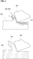
- FIG. 1 An upper illustration in Fig. 1 schematically shows how a green compact 200 is machined with a cutting tool 100, and a lower illustration schematically shows how a solidified metal body 300 is machined with the cutting tool 100.
- the green compact 200 formed by packing metal particles 202 under pressure, the green compact 200 is machined such that the metal particles 202 are torn off the surface of the green compact 200 by the cutting tool 100. Therefore, machining chips 201 generated as a result of machining are composed of metal powder of metal particles 202 separated from the green compact 200.
- the powdery machining chips 201 can be reused without melting.
- the clusters may be pulverized as needed.
- the solidified metal body 300 is machined such that the surface of the solidified metal body 300 is shaved off by the cutting tool 100. Machining chips 301 generated by machining are composed of elongated structures and must be melted for reuse.
- the surface of the green compact Before the machining, the surface of the green compact may be coated or impregnated with a volatile or plastic solution containing an organic binder dissolved therein in order to prevent chipping and cracking from occurring in the surface layer of the green compact during machining.
- the green compact may be machined while compressive stress is applied to the green compact in such a direction that the tensile stress acting on the green compact is counteracted to thereby prevent chipping and cracking from occurring in the green compact.
- compressive stress is applied to the green compact in such a direction that the tensile stress acting on the green compact is counteracted to thereby prevent chipping and cracking from occurring in the green compact.
- strong tensile stress acts on a portion near an opening of the machined hole from which the broach protrudes when it pierces the green compact.
- One method for applying the compressive stress that counteracts the tensile stress to a green compact is to stack a plurality of green compacts one on top of another. It is preferable to dispose a dummy green compact, a plate material, etc. below the lowermost green compact.
- the machined compact obtained by machining the green compact is sintered.
- a sintered body in which the particles of the metal powder are in contact with each other and bonded together is obtained.
- well-known conditions suitable for the composition of the metal powder can be used.
- the sintering temperature is, for example, from 1,100°C to 1,400°C and from 1,200°C to 1,300°C inclusive.
- the sintering time is, for example, from 15 minutes to 150 minutes inclusive and from 20 to 60 minutes inclusive.
- the degree of machining in the machining step may be adjusted according to the difference between the actual dimensions of the sintered body and its design dimensions.
- the machined compact prepared by machining the high-density green compact with a relative density or 93% or more contracts substantially uniformly during sintering. Therefore, by adjusting the degree of machining in the machining step according to the difference between the actual dimensions after sintering and the design dimensions, the actual dimensions of the sintered body can be very close to the design dimensions. This allows time and effort in the subsequent finish machining to be reduced. When a machining center is used for the machining, the degree of machining can be easily adjusted.
- the surface of the sintered body is, for example, polished.
- the surface roughness of the sintered body is thereby reduced, and the dimensions of the sintered body are adjusted to the design dimensions.
- the overall average relative density of the sintered body is approximately the same as the overall average relative density of the unsintered green compact.
- the overall average relative density of the sintered body is preferably 95% or more, more preferably 96% or more, and still more preferably 97% or more. The larger the average relative density, the higher the strength of the sintered body.
- the captured image of each viewing field is subjected to binarization processing to determine the ratio of the area of the metal particles in the viewing field, and the ratio of the area is regarded as the relative density in the viewing field. Then the relative densities determined in the viewing fields are averaged to compute the overall average relative density of the green compact.
- the pressing axis direction of the sintered body can be easily found by observing the deformation state of the metal powder in the cross sections of the sintered body because the sintered body has been uniaxially pressed in its production process.
- the position near one end (the other end) is, for example, a position within 3 mm from a surface of the green compact.
- the sintered body manufacturing method in the embodiment and a conventional sintered body manufacturing method were used to produce assemblies 1 shown in Fig. 2 and each including planetary gears 2 and a planetary carrier 3.
- Each planetary gear 2 is a helical gear having teeth 20 extending obliquely to an axial line as shown in Fig. 3 (see a dash-dot line).
- the planetary carrier 3 includes a disk-shaped first member 31 and a second member 32 having three bridge portions 32b formed in its disk portion 32s.
- a raw material powder was prepared by mixing an Fe-2 mass % Ni-0.5 mass % Mo alloy powder with 0.3% by mass of C (graphite) powder.
- the true density of the raw material powder was about 7.8 g/cm 3 .
- the raw material powder was pressure-molded by uniaxial pressing to produce the following three types of green compacts.
- the molding pressure was 1,200 MPa for each of these cases.
- the overall average relative densities of these three types of green compacts were determined and found to be 93% or more.
- the green compacts for the planetary gears 2 were machined to form teeth 20 inclined 50° with respect to their axial line.
- the green compact for the first member 31 was machined to form a boss portion 31b by shaving as shown in Fig. 1 .
- a hole was formed at the center of the boss portion 31b, and teeth of an internal gear were formed inside the hole.
- the green compact for the second member 32 was machined to form the bridge portions 32b by shaving. Then, as shown in the lower illustration in Fig.
- an inner circumferential surface portion (a portion indicated by a black arrow) included in a base portion of each bridge portion 32b and connected to the disk portion 32s was formed into an R shape.
- the strength of the bridge portions 32b can be improved.
- the machined compacts were sintered to produce the planetary gears 2 and planetary carrier 3 composed of the sintered bodies. During the sintering, no chipping and cracking occurred in the sintered bodies. Finally, the planetary gears 2 and the planetary carrier 3 were, for example, polished so that their dimensions were closer to the design dimensions and their surface roughness was reduced.
- the average relative densities of the planetary gears 2 and the planetary carrier 3 in sample A were determined and found to be about 93% or more.
- the average relative density was converted to an average bulk density, and the average bulk density of each of the planetary gears 2 and the planetary carrier 3 was 7.5 g/cm 3 .
- the viewing fields captured in the cross sections include portions of the teeth 20 of the planetary gears 2. The relative density of only these portions was determined and found to be 96.2%.
- the planetary gears 2 and the planetary carrier 3 in sample A had mechanical strength comparable to that of planetary gears and a planetary carrier formed from solidified metal bodies produced by a melting method. It was therefore found that the planetary gears 2 and the planetary carrier 3 in sample A can be sufficiently used for components of automobiles.
- the same raw material powder as sample A was prepared and subjected to near net shape molding to produce green compacts having a shape close to the shape of the planetary gears 2 and a green compact having a shape close to the shape of the planetary carrier 3. Since the planetary gears 2 are helical gears, a rotary press was used for near net shape molding of the planetary gears 2. With the rotary press, the inclination of the teeth 20 with respect to the axial line cannot be 45° or more. With the rotary press, the available molding pressure was much lower than 600 MPa.
- the near-net shaped green compacts were sintered and subjected to finish machining to thereby produce planetary gears 2 and a planetary carrier 3 in sample B.
- the relative densities of viewing fields in cross sections were determined by the same method as that for sample A. The relative densities were different for different viewing fields. Specifically, in the teeth 20 of the planetary gear 2, the average relative density was about 88.5% (average bulk density: 6.9 g/cm 3 ). In portions other than the teeth 20, the average relative density was about 89.7% (average bulk density: 7.0 g/cm 3 ). The overall average relative density of sample B was about 89%.
- the mechanical strength of the planetary gears 2 and the planetary carrier 3 in sample B was much worse than that of a planetary gear and a planetary carrier formed from solidified metal bodies produced by a melting method.
- the planetary gears 2 and the planetary carrier 3 in sample B may be unsuitable for components of automobiles.
- the sintered body manufacturing method in the embodiment can be preferably used to produce a sintered member having a complicated shape that is difficult to produce only by pressure molding using a die.
- the sintered body manufacturing method in the embodiment can be used to produce, for example, sprockets, rotors, gears, rings, flanges, pulleys, vanes, bearings, etc. used for machines such as automobiles.
Landscapes
- Engineering & Computer Science (AREA)
- Mechanical Engineering (AREA)
- Chemical & Material Sciences (AREA)
- Manufacturing & Machinery (AREA)
- Materials Engineering (AREA)
- Metallurgy (AREA)
- Organic Chemistry (AREA)
- Nanotechnology (AREA)
- Powder Metallurgy (AREA)
Abstract
Description
- The present invention relates to a method for manufacturing a sintered body and to a sintered body.
- The present application claims priority from Japanese Patent Application No.
2016-077069 filed on April 7, 2016 -
PTL 1 discloses a metallic member manufacturing method (a sintered body manufacturing method) comprising: calcining a compact prepared by pressure molding of a metal powder; machining the calcined compact; and then subjecting the machined compact to main firing. In the manufacturing method inPTL 1, the calcined compact prepared by calcining the compact has higher mechanical strength than the uncalcined compact, is less likely to chip during machining, and is therefore easily machined. The calcined compact has a lower hardness than the sintered body subjected to the main firing and is therefore easily machined. Specifically, in the manufacturing method inPTL 1, the green compact is calcined to increase its mechanical strength, and then the calcined compact is machined, so that chipping and cracking are less likely to occur during the machining. - PTL 1: Japanese Unexamined Patent Application Publication No.
2007-77468 - The sintered body manufacturing method of the present disclosure comprises:
- a preparation step of preparing a raw material powder containing an iron-based metal powder;
- a molding step of subjecting the raw material powder to uniaxial pressing using a die to produce a green compact having an overall average relative density of 93% or more;
- a machining step of machining the green compact to produce a machined compact; and
- a sintering step of sintering the machined compact to obtain a sintered body.
- The sintered body of the present disclosure is an iron-based sintered body having an overall average relative density of 93% or more.
-
- [
Fig. 1] Figure 1 shows schematic illustrations of machining with a cutting tool, an upper illustration showing how a green compact is machined with the cutting tool, a lower illustration showing how a solidified metal body is machined with the cutting tool. - [
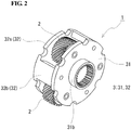
Fig. 2] Figure 2 is a schematic perspective view of an assembly described in a production example and including a planetary carrier and planetary gears. - [
Fig. 3] Figure 3 is a schematic side view of a planetary gear described in the production example. - [
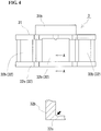
Fig. 4] Figure 4 shows the planetary carrier described in the production example, an upper illustration being a schematic front view, a lower illustration being an A-Across section of the upper illustration. - In the metal member manufacturing method in
PTL 1, since the green compact is calcined, particles of the metal powder are sintered to some extent. Although the hardness of the calcined compact is lower than the hardness of the sintered body subjected to the main firing, the calcined compact has a certain hardness. Therefore, the technique inPTL 1 is susceptible to improvement in machinability. Moreover, since the particles of the metal powder are sintered during the calcination, machining chips must be melted in order to reuse the machining chips. - In the metal member manufacturing method in
PTL 1, pressure molding, calcination, machining, and main firing are performed sequentially, and the number of steps for obtaining the metal member is large. Therefore, the technique inPTL 1 is susceptible to improvement in metal member productivity. - One object of the present disclosure is to provide a high-productivity sintered body manufacturing method in which an unsintered green compact can be easily machined.
- In the sintered body manufacturing method of the present disclosure, the unsintered green compact can be easily machined, and therefore the sintered body of the present disclosure can be manufactured with high productivity.
-
- <1> A sintered body manufacturing method according to an embodiment comprises:
- a preparation step of preparing a raw material powder containing an iron-based metal powder;
- a molding step of subjecting the raw material powder to uniaxial pressing using a die to produce a green compact having an overall average relative density of 93% or more;
- a machining step of machining the green compact to produce a machined compact; and
- a sintering step of sintering the machined compact to obtain a sintered body.
- In the above sintered body manufacturing method, the green compact is produced by uniaxial pressing using the die. In the uniaxial pressing, the raw material powder can be molded under application of very high contact pressure. Therefore, a green compact having a high and uniform relative density with no brittle portions present locally can be easily obtained. The green compact obtained by uniaxial pressing is excellent in mechanical strength, and chipping and cracking are less likely to occur during machining. Specifically, since the green compact obtained by uniaxial pressing can be subjected to the machining step without calcination, the sintered body manufacturing method can produce the sintered body with high productivity.
- In the above sintered body manufacturing method, the green compact produced has a uniform relative density of 93% or more. Therefore, when the machined compact prepared by machining the green compact is sintered, the change in the dimensions of the machined compact is stabilized. Specifically, the degree of contraction of the machined compact does not vary locally, and the entire machined compact contracts substantially uniformly. This can prevent the actual dimensions of the sintered body from deviating largely from the design dimensions. Preferably, the relative density is 95% or more.
- In the above sintered body manufacturing method, since the green compact is subjected to the machining step without sintering, machining resistance during the machining step is low. Therefore, the speed of machining can be about 5 to about 10 times faster than that when a solidified metal body is machined, and the life of tools used for the machining can be about 10 to about 100 times longer. Since the machining resistance of the green compact is low, the stiffness of cutting tools and shanks can be low, and long or small-diameter cutting tools and shanks can be used for machining. Since flexibility in selection of cutting tools and shanks is high as described above, fewer constraints are imposed on the design of the shape of the sintered body, i.e., its design flexibility is high. For example, a finely machined sintered body such as a hollowed sintered body can be produced.
- In the above sintered body manufacturing method, the machining chips generated during the machining can be reused without melting the chips. This is because, since the green compact is produced by cold pressure molding and is not sintered before machining, the metal powder contained in the machining chips is not altered.
-
- <2> In one mode of the sintered body manufacturing method according to the embodiment, the green compact is machined into a helical gear shape in the machining step.
- In the sintered body manufacturing method according to the embodiment, since the green compact is machined before it is sintered, the green compact can be easily machined into a complex helical gear shape.
-
- <3> In another mode of the sintered body manufacturing method according to the embodiment, the uniaxial pressing is performed at a pressure of 600 MPa or higher.
- When the green compact is produced in the above pressure range, the green compact obtained can have a high density and excellent machinability.
- <4> In another mode of the sintered body manufacturing method according to the embodiment, the machining step is performed using a cutting method.
- The cutting may be performed using at least one working tool such as a milling cutter, a hob, a broach, or a pinion cutter. Since the green compact is excellent in machinability, the cutting can be easily performed with high precision using any of the above working tools.
- <5> In another mode of the sintered body manufacturing method according to the embodiment, the machining step is performed while compressive stress is applied to the green compact in such a direction that tensile stress acting on the green compact from a working tool is counteracted.
- When the machining is performed while the compressive stress is applied to the green compact in such a direction that the tensile stress acting on the green compact is counteracted, the occurrence of chipping and cracking in the green compact can be effectively prevented. Means for applying the compressive stress will be exemplified in an embodiment described later.
- <6> A sintered body according to another embodiment,
the sintered body composed of an iron-based material comprising:- an average relative density of the whole sintered body being 93% or more.
- The sintered body in this embodiment has an average relative density of 93% or more and is a novel innovative sintered body. Since the average relative density of the sintered body in the embodiment is 93% or more, its mechanical strength compares favorably with that of a machined product prepared from a solidified metal body. The sintered body in this embodiment is manufactured by the sintered body manufacturing method in the preceding embodiment. Therefore, the sintered body can be manufactured with higher productivity than a machined product prepared from a solidified metal body. Preferably, the average relative density is 95% or more.
- <7> In one mode of the sintered body according to this embodiment, the sintered body is a helical gear.
- The sintered helical gear can be used as, for example, a component of a transmission of an automobile. As described above, the sintered body according to the embodiment has a mechanical strength that compares favorably with that of a machined product prepared from a solidified metal body. Therefore, the sintered body sufficiently functions as a component of an automobile to which a high load is applied.
- <8> In one mode of the sintered body according to the embodiment that has the helical gear shape, the helical gear has teeth inclined 30° or more with respect to an axial line of the helical gear.
- Since the above helical gear has excellent mechanical strength, the teeth of the helical gear are less likely to be damaged during use even when the teeth are inclined 30° or more with respect to the axial line. As the angle of the teeth with respect to the axial line increases, the noise generated when the helical gear is engaged with another gear is further reduced. Preferably, the angle of the teeth with respect to the axial line is 50° or more.
- A specific example of a sintered body manufacturing method according to an embodiment of the present invention will be described with reference to the drawings. However, the present invention is not limited to this example. The present invention is defined by the scope of the claims and is intended to include any modifications within the scope and meaning equivalent to the scope of the claims.
- The sintered body manufacturing method according to the embodiment comprises the following steps.
- S1. Preparation step: A raw material powder containing an iron-based metal powder is prepared.
- S2. Molding step: The raw material powder is subjected to uniaxial pressing using a die to produce a green compact having an overall average relative density of 93% or more.
- S3. Machining step: The green compact is machined to produce a machined compact.
- S4. Sintering step: The machined compact is sintered to obtain a sintered body.
- S5. Finishing step: Finish machining is performed so that the actual dimensions of the sintered body are closer to its design dimensions.
- These steps will be described in detail.
- The metal powder is a main material forming the sintered body, and examples of the metal powder include an iron powder and an iron alloy powder composed mainly of iron. Typically, the metal powder used is a pure iron powder or an iron alloy powder. The "iron powder composed mainly of iron" means that the iron alloy contains, as its component, elemental iron in an amount of more than 50% by mass, preferably 80% by mass or more, and more preferably 90% by mass or more. Examples of the iron alloy include an alloy containing at least one alloying element selected from Cu, Ni, Sn, Cr, Mo, Mn, and C. The above alloying elements contribute to improvement in the mechanical properties of the iron-based sintered body. Among the above alloying elements, Cu, Ni, Sn, Cr, Mn, and Mo are contained in a total amount of from 0.5% by mass to 5.0% by mass inclusive and from 1.0% by mass to 3.0% by mass inclusive. The content of C is from 0.2% by mass to 2.0% by mass inclusive and from 0.4% by mass to 1.0 mass inclusive. The metal powder used may be an iron powder, and a powder of any of the above alloying elements (an alloying powder) may be added to the iron powder. In this case, the component of the metal powder in the raw material powder is iron. However, the iron reacts with the alloying element during sintering in the subsequent sintering step and is thereby alloyed. In the raw material powder, the content of the metal powder (including the alloying powder) is, for example, 90% by mass or more and is 95% by mass or more. The metal powder used may be produced by, for example, a water atomization method, a gas atomization method, a carbonyl method, or a reduction method.
- The average particle diameter of the metal powder is, for example, from 20 µm to 200 µm inclusive and from 50 µm to 150 µm inclusive. When the average particle diameter of the metal powder is within the above range, the metal powder is easy to handle and is easily pressure-molded in the subsequent molding step (S2). When the average particle diameter of the metal powder is 20 µm or more, the flowability of the raw material powder can be easily ensured. When the average particle diameter of the metal powder is 200 µm or less, a sintered body with a dense structure can be easily obtained. The average particle diameter of the metal powder is the average particle diameter of the particles included in the metal powder and is a particle diameter (D50) at which a cumulative volume in a volumetric particle size distribution measured by a laser diffraction particle size distribution measurement apparatus is 50%. The use of the fine-grain metal powder allows the surface roughness of the sintered body to be reduced and its corner edges to be sharpened.
- In press forming using a die, a raw material powder prepared by mixing a metal powder and an internal lubricant is generally used to prevent the metal powder from sticking to the die. However, in this example, the raw material powder contains no internal lubricant. When the raw material powder contains an internal lubricant, the content of the internal lubricant is 0.2% by mass or less based on the total mass of the raw material powder. This is because a reduction in the ratio of the metal powder in the raw material powder is prevented to obtain a green compact with a relative density or 93% or more in the molding step described later. However, the raw material powder is allowed to contain a small amount of an internal lubricant so long as a green compact with a relative density or 93% or more can be produced in the subsequent molding step. The internal lubricant used can be a metallic soap such as lithium stearate or zinc stearate.
- To prevent the occurrence of chipping and cracking in the green compact in the machining step described later, an organic binder may be added to the raw material powder. Examples of the organic binder include polyethylene, polypropylene, polyolefin, polymethyl methacrylate, polystyrene, polyvinyl chloride, polyvinylidene chloride, polyamide, polyester, polyether, polyvinyl alcohol, vinyl acetate, paraffin, and various waxes. The organic binder may be added as needed or may not be added. When the organic binder is added, the amount of the organic binder added is such that a green compact with a relative density or 93% or more can be produced in the subsequent molding step.
- In the molding step, a die is used to uniaxial press the raw material powder to thereby produce a green compact. The die used for the uniaxial pressing includes a die block and a pair of punches to be fitted into upper and lower openings of the die block. The raw material powder filled into a cavity of the die block is compressed by the upper and lower punches to thereby produce a green compact. The green compact that can be formed using this die has a simple shape. Examples of the simple shape include a circular columnar shape, a circular tubular shape, a prismatic columnar shape, and a prismatic tubular shape. A punch having a projection or recess on its punching surface may be used. In this case, a recess or projection corresponding to the projection or recess of the punch is formed in the green compact having the simple shape. The green compact having the simple shape is intended to include such a green compact having a recess or projection.
- The pressure (contact pressure) during the uniaxial pressing may be 600 MPa or higher. By increasing the contact pressure, the relative density of the green compact can be increased. The contact pressure is preferably 1,000 MPa or higher. The contact pressure is more preferably 1,500 MPa or higher. The upper limit of the contact pressure is not particularly specified.
- In the uniaxial molding, it is preferable to apply an external lubricant to inner circumferential surfaces of the die (the inner circumferential surface of the die block and the pressing surfaces of the punches) in order to prevent the metal powder from sticking to the die. The external lubricant used may be a metallic soap such as lithium stearate or zinc stearate. Alternatively, the external lubricant used may be a fatty acid amide such as lauric acid amide, stearic acid amide, or palmitic acid amide or a higher fatty acid amide such as ethylene bis-stearic acid amide.
- The overall average relative density of the green compact obtained by uniaxial pressing is 93% or more. The overall average relative density of the green compact is preferably 95% or more, more preferably 96% or more, and still more preferably 97% or more. The overall average relative density of the green compact can be determined as follows. Cross sections of the green compact that intersect the direction of a pressing axis (preferably cross sections perpendicular to the pressing axis direction) are taken at a position near the center in the pressing axis direction, a position near one end, and a position near the other end. Then the cross sections are subjected to image analysis. More specifically, first, images of a plurality of viewing fields are captured in each cross section. For example, images of 10 or more viewing fields having an area of 500 µm × 600 µm = 300,000 µm2 are captured in each cross section. Preferably, the images of the viewing fields are captured in each cross section from positions distributed uniformly as much as possible. Next, the captured image of each viewing field is subjected to binarization processing to determine the ratio of the area of the metal particles in the viewing field, and the ratio of the area is regarded as the relative density in the viewing field. Then the relative densities determined in the viewing fields are averaged to compute the overall average relative density of the green compact. The position near one end (the other end) is, for example, a position within 3 mm from a surface of the green compact.
- In the machining step, after the green compact has been produced by uniaxial pressing, the green compact is machined without sintering. The machining is typically cutting, and a cutting tool is used to machine the green compact into a prescribed shape. Examples of the cutting include milling and lathe turning. Examples of the milling include drilling. Examples of the cutting tool used for drilling include a drill and a reamer, and examples of the cutting tool used for milling include a milling cutter and an end mill. Examples of the cutting tool used for lathe turning include a turning tool and an indexable cutting insert. Moreover, the cutting may be performed using a hob, a broach, a pinion cutter, etc. A machining center that can automatically perform a plurality of types of processing may be used for machining.
- The concept of machining will be described with reference to conceptual illustrations in
Fig. 1 . An upper illustration inFig. 1 schematically shows how agreen compact 200 is machined with acutting tool 100, and a lower illustration schematically shows how a solidifiedmetal body 300 is machined with thecutting tool 100. As shown in the upper illustration inFig. 1 , in the green compact 200 formed by packingmetal particles 202 under pressure, thegreen compact 200 is machined such that themetal particles 202 are torn off the surface of the green compact 200 by thecutting tool 100. Therefore, machiningchips 201 generated as a result of machining are composed of metal powder ofmetal particles 202 separated from thegreen compact 200. Thepowdery machining chips 201 can be reused without melting. When clusters of aggregatedmetal particles 202 are present, the clusters may be pulverized as needed. As shown in the lower illustration inFig. 1 , the solidifiedmetal body 300 is machined such that the surface of the solidifiedmetal body 300 is shaved off by thecutting tool 100.Machining chips 301 generated by machining are composed of elongated structures and must be melted for reuse. - Before the machining, the surface of the green compact may be coated or impregnated with a volatile or plastic solution containing an organic binder dissolved therein in order to prevent chipping and cracking from occurring in the surface layer of the green compact during machining.
- The green compact may be machined while compressive stress is applied to the green compact in such a direction that the tensile stress acting on the green compact is counteracted to thereby prevent chipping and cracking from occurring in the green compact. For example, when the green compact is broached to form a machined hole, strong tensile stress acts on a portion near an opening of the machined hole from which the broach protrudes when it pierces the green compact. One method for applying the compressive stress that counteracts the tensile stress to a green compact is to stack a plurality of green compacts one on top of another. It is preferable to dispose a dummy green compact, a plate material, etc. below the lowermost green compact. When a plurality of green compacts are stacked one on top of another, the lower surface of an upper green compact is pressed against the upper surface of a lower green compact, and compressive stress is thereby applied to the lower surface. When broaching is performed on the stacked green compacts from above, chipping and cracking can be effectively prevented from occurring near the openings of the machined hole which are formed on the lower surfaces of the green compacts and from which the broach protrudes. When a machined groove is formed in a green compact by milling, strong tensile stress acts on a portion near an end of the machined groove. To address this problem, a plurality of green compacts are arranged in the moving direction of the milling cutter such that compressive stress acts on portions corresponding to the ends of the groove.
- In the sintering step, the machined compact obtained by machining the green compact is sintered. By sintering the green compact, a sintered body in which the particles of the metal powder are in contact with each other and bonded together is obtained. To sinter the green compact, well-known conditions suitable for the composition of the metal powder can be used. For example, when the metal powder is an iron powder or an iron alloy powder, the sintering temperature is, for example, from 1,100°C to 1,400°C and from 1,200°C to 1,300°C inclusive. The sintering time is, for example, from 15 minutes to 150 minutes inclusive and from 20 to 60 minutes inclusive.
- The degree of machining in the machining step may be adjusted according to the difference between the actual dimensions of the sintered body and its design dimensions. The machined compact prepared by machining the high-density green compact with a relative density or 93% or more contracts substantially uniformly during sintering. Therefore, by adjusting the degree of machining in the machining step according to the difference between the actual dimensions after sintering and the design dimensions, the actual dimensions of the sintered body can be very close to the design dimensions. This allows time and effort in the subsequent finish machining to be reduced. When a machining center is used for the machining, the degree of machining can be easily adjusted.
- In the finishing step, the surface of the sintered body is, for example, polished. The surface roughness of the sintered body is thereby reduced, and the dimensions of the sintered body are adjusted to the design dimensions.
- With the sintered body manufacturing method described above, a sintered body with an overall average relative density of 93% or more can be obtained. The overall average relative density of the sintered body is approximately the same as the overall average relative density of the unsintered green compact. The overall average relative density of the sintered body is preferably 95% or more, more preferably 96% or more, and still more preferably 97% or more. The larger the average relative density, the higher the strength of the sintered body.
- The overall average relative density of the sintered body can be determined as follows. Cross sections of the sintered body that intersect the pressing axis direction (preferably cross sections perpendicular to the pressing axis direction) are taken at a position near the center in the pressing axis direction, a position near one end, and a position near the other end. Then the cross sections are subjected to image analysis. More specifically, first, images of a plurality of viewing fields are captured in each cross section. For example, images of 10 or more viewing fields having an area of 500 µm × 600 µm = 300,000 µm2 are captured in each cross section. Preferably, the images of the viewing fields are captured in each cross section from positions distributed uniformly as much as possible. Next, the captured image of each viewing field is subjected to binarization processing to determine the ratio of the area of the metal particles in the viewing field, and the ratio of the area is regarded as the relative density in the viewing field. Then the relative densities determined in the viewing fields are averaged to compute the overall average relative density of the green compact. The pressing axis direction of the sintered body can be easily found by observing the deformation state of the metal powder in the cross sections of the sintered body because the sintered body has been uniaxially pressed in its production process. The position near one end (the other end) is, for example, a position within 3 mm from a surface of the green compact.
- In production examples, the sintered body manufacturing method in the embodiment and a conventional sintered body manufacturing method were used to produce
assemblies 1 shown inFig. 2 and each includingplanetary gears 2 and aplanetary carrier 3. Eachplanetary gear 2 is a helicalgear having teeth 20 extending obliquely to an axial line as shown inFig. 3 (see a dash-dot line). As shown inFigs. 2 and4 , theplanetary carrier 3 includes a disk-shapedfirst member 31 and asecond member 32 having threebridge portions 32b formed in itsdisk portion 32s. - First, a raw material powder was prepared by mixing an Fe-2 mass % Ni-0.5 mass % Mo alloy powder with 0.3% by mass of C (graphite) powder. The true density of the raw material powder was about 7.8 g/cm3.
- Next, the raw material powder was pressure-molded by uniaxial pressing to produce the following three types of green compacts. The molding pressure was 1,200 MPa for each of these cases.
- A cylindrical green compact for a
planetary gear 2 diameter: 50 mm, height: 20 mm - A disk-shaped green compact for the
first member 31 diameter: 130 mm, height: 35 mm - A cylindrical green compact for the
second member 32 diameter: 130 mm, height: 35 mm - The overall average relative densities of these three types of green compacts were determined and found to be 93% or more. As described in «S2. Molding step» above, the average relative density of each green compact was determined as follows. Cross sections of the green compact were taken at a position near the center in the pressing axis direction and positions near the opposite ends. Images of 10 or more viewing fields having an area of 500 µm × 600 µm = 300,000 µm2 were captured in each cross section and subjected to image analysis. Specifically, the average relative density of the green compact was about 96.2%. The average relative density was converted to an average bulk density, and the average bulk density of the green compact was 7.5 g/cm3.
- Next, a commercial machining center was used to machine each of the green compacts produced, and machined compacts having desired shapes were thereby produced. The green compacts for the
planetary gears 2 were machined to formteeth 20 inclined 50° with respect to their axial line. The green compact for thefirst member 31 was machined to form aboss portion 31b by shaving as shown inFig. 1 . Then a hole was formed at the center of theboss portion 31b, and teeth of an internal gear were formed inside the hole. The green compact for thesecond member 32 was machined to form thebridge portions 32b by shaving. Then, as shown in the lower illustration inFig. 4 , an inner circumferential surface portion (a portion indicated by a black arrow) included in a base portion of eachbridge portion 32b and connected to thedisk portion 32s was formed into an R shape. When the inner circumferential surface portion is formed into an R shape, the strength of thebridge portions 32b can be improved. During the machining of any of the above green compacts, no chipping and cracking occurred in the green compacts. The machining chips generated by machining were composed of metal powder of metal particles separated from the green compacts. - Next, the machined compacts were sintered to produce the
planetary gears 2 andplanetary carrier 3 composed of the sintered bodies. During the sintering, no chipping and cracking occurred in the sintered bodies. Finally, theplanetary gears 2 and theplanetary carrier 3 were, for example, polished so that their dimensions were closer to the design dimensions and their surface roughness was reduced. - The average relative densities of the
planetary gears 2 and theplanetary carrier 3 in sample A were determined and found to be about 93% or more. As described in <<Sintered body>> above, the average relative density of each of theplanetary gears 2 and the planetary carrier 3 (sintered bodies) was determined as flows. Cross sections were taken at a position near the center in the pressing axis direction and positions near opposite ends. Images of 10 or more viewing fields having an area of 500 µm × 600 µm = 300,000 µm2 were subjected to image analysis. Specifically, the average relative density of each of theplanetary gears 2 and theplanetary carrier 3 was about 96.2%. The average relative density was converted to an average bulk density, and the average bulk density of each of theplanetary gears 2 and theplanetary carrier 3 was 7.5 g/cm3. The viewing fields captured in the cross sections include portions of theteeth 20 of theplanetary gears 2. The relative density of only these portions was determined and found to be 96.2%. - The
planetary gears 2 and theplanetary carrier 3 in sample A had mechanical strength comparable to that of planetary gears and a planetary carrier formed from solidified metal bodies produced by a melting method. It was therefore found that theplanetary gears 2 and theplanetary carrier 3 in sample A can be sufficiently used for components of automobiles. - The same raw material powder as sample A was prepared and subjected to near net shape molding to produce green compacts having a shape close to the shape of the
planetary gears 2 and a green compact having a shape close to the shape of theplanetary carrier 3. Since theplanetary gears 2 are helical gears, a rotary press was used for near net shape molding of theplanetary gears 2. With the rotary press, the inclination of theteeth 20 with respect to the axial line cannot be 45° or more. With the rotary press, the available molding pressure was much lower than 600 MPa. - The near-net shaped green compacts were sintered and subjected to finish machining to thereby produce
planetary gears 2 and aplanetary carrier 3 in sample B. For each of theplanetary gears 2 and theplanetary carrier 3 in sample B, the relative densities of viewing fields in cross sections were determined by the same method as that for sample A. The relative densities were different for different viewing fields. Specifically, in theteeth 20 of theplanetary gear 2, the average relative density was about 88.5% (average bulk density: 6.9 g/cm3). In portions other than theteeth 20, the average relative density was about 89.7% (average bulk density: 7.0 g/cm3). The overall average relative density of sample B was about 89%. - The mechanical strength of the
planetary gears 2 and theplanetary carrier 3 in sample B was much worse than that of a planetary gear and a planetary carrier formed from solidified metal bodies produced by a melting method. In particular, since the relative density of theteeth 20 of theplanetary gear 2 to which high stress is applied during use is low, theplanetary gears 2 and theplanetary carrier 3 in sample B may be unsuitable for components of automobiles. - The sintered body manufacturing method in the embodiment can be preferably used to produce a sintered member having a complicated shape that is difficult to produce only by pressure molding using a die. The sintered body manufacturing method in the embodiment can be used to produce, for example, sprockets, rotors, gears, rings, flanges, pulleys, vanes, bearings, etc. used for machines such as automobiles.
-
- 1
- assembly
- 2
- planetary gear, 20 tooth
- 3
- planetary carrier
- 31
- first member, 31b boss portion
- 32
- second member, 32s disk portion, 32b bridge portion
- 100
- cutting tool
- 200
- green compact, 201 machining chips, 202 metal particle
- 300
- solidified metal body, 301 machining chips
Claims (8)
- A method for manufacturing a sintered body, the method comprising:a preparation step of preparing a raw material powder containing an iron-based metal powder;a molding step of subjecting the raw material powder to uniaxial pressing using a die to produce a green compact having an overall average relative density of 93% or more;a machining step of machining the green compact to produce a machined compact; anda sintering step of sintering the machined compact to obtain a sintered body.
- The method for manufacturing a sintered body according to claim 1, wherein, in the machining step, the green compact is machined into a helical gear shape.
- The method for manufacturing a sintered body according to claim 1 or 2, wherein the uniaxial pressing is performed at a pressure of 600 MPa or higher.
- The method for manufacturing a sintered body according to any one of claims 1 to 3, wherein the machining step is performed using a cutting method.
- The method for manufacturing a sintered body according to any one of claims 1 to 4, wherein the machining step is performed while compressive stress is applied to the green compact in such a direction that tensile stress acting on the green compact from a working tool is counteracted.
- A sintered body composed of an iron-based material comprising:an average relative density of the whole sintered body being 93% or more.
- The sintered body according to claim 6, wherein the sintered body is a helical gear.
- The sintered body according to claim 7, wherein the helical gear has teeth inclined 30° or more with respect to an axial line of the helical gear.
Applications Claiming Priority (2)
| Application Number | Priority Date | Filing Date | Title |
|---|---|---|---|
| JP2016077069A JP6509771B2 (en) | 2016-04-07 | 2016-04-07 | Method of manufacturing sintered body |
| PCT/JP2017/014145 WO2017175772A1 (en) | 2016-04-07 | 2017-04-04 | Method for manufacturing sintered compact, and sintered compact |
Publications (3)
| Publication Number | Publication Date |
|---|---|
| EP3441161A1 true EP3441161A1 (en) | 2019-02-13 |
| EP3441161A4 EP3441161A4 (en) | 2019-02-13 |
| EP3441161B1 EP3441161B1 (en) | 2024-07-17 |
Family
ID=60001295
Family Applications (1)
| Application Number | Title | Priority Date | Filing Date |
|---|---|---|---|
| EP17779150.6A Active EP3441161B1 (en) | 2016-04-07 | 2017-04-04 | Method for manufacturing sintered compact, and sintered compact |
Country Status (5)
| Country | Link |
|---|---|
| US (1) | US20180236548A1 (en) |
| EP (1) | EP3441161B1 (en) |
| JP (1) | JP6509771B2 (en) |
| CN (1) | CN107921535B (en) |
| WO (1) | WO2017175772A1 (en) |
Cited By (1)
| Publication number | Priority date | Publication date | Assignee | Title |
|---|---|---|---|---|
| DE202024100893U1 (en) | 2023-11-29 | 2024-04-04 | Sacmi Cooperativa Meccanici Imola Societa' Cooperativa | Device for pressing metal powders to produce helical gears |
Families Citing this family (19)
| Publication number | Priority date | Publication date | Assignee | Title |
|---|---|---|---|---|
| US20210162499A1 (en) * | 2017-05-26 | 2021-06-03 | Sumitomo Electric Industries, Ltd. | Method for manufacturing sintered member |
| WO2019181453A1 (en) * | 2018-03-22 | 2019-09-26 | 日本電産株式会社 | Raw material powder, sintered gear production method, and sintered gear |
| JP7221028B2 (en) * | 2018-11-15 | 2023-02-13 | 住友電気工業株式会社 | Manufacturing method of sintered gear |
| DE112019006775T5 (en) | 2019-01-30 | 2021-11-04 | Sumitomo Electric Industries, Ltd. | SINTER MATERIAL AND PROCESS FOR MANUFACTURING SINTERED MATERIAL |
| JPWO2020158788A1 (en) * | 2019-01-30 | 2021-12-02 | 住友電気工業株式会社 | Sintered materials, gears, and methods for manufacturing sintered materials |
| DE112020001074T5 (en) | 2019-03-05 | 2021-12-23 | Sumitomo Electric Industries, Ltd. | Process for the production of a sintered part |
| US20220176448A1 (en) | 2019-04-24 | 2022-06-09 | Sumitomo Electric Sintered Alloy, Ltd. | Manufacturing system and manufacturing method of sintered product |
| DE112020002102T5 (en) | 2019-04-24 | 2022-03-10 | Sumitomo Electric Industries, Ltd. | Process for the production of sintered bodies and powder compacts |
| WO2020226111A1 (en) * | 2019-05-08 | 2020-11-12 | 住友電気工業株式会社 | Sintered gear manufacturing method |
| US12085897B2 (en) * | 2019-07-22 | 2024-09-10 | Fossil Group, Inc. | Subtractive manufacturing of an oversized MIM blank |
| US11707785B1 (en) * | 2019-07-22 | 2023-07-25 | Keystone Powdered Metal Company | Powder metal parts with improved machinability |
| WO2021038878A1 (en) * | 2019-08-30 | 2021-03-04 | 住友電気工業株式会社 | Sintered material and method for producing sintered material |
| DE112019007673T5 (en) * | 2019-08-30 | 2022-06-15 | Sumitomo Electric Industries, Ltd. | sintered gear |
| US11802617B2 (en) | 2020-10-22 | 2023-10-31 | Sumitomo Electric Industries, Ltd. | Method of manufacturing sintered gear |
| CN112775429A (en) * | 2020-12-24 | 2021-05-11 | 朱亚岩 | Manufacturing method of lettering die |
| CN113098163B (en) * | 2021-04-19 | 2023-03-24 | 云南铜业压铸科技有限公司 | Preparation method of cast copper rotor for high-rotation-speed motor |
| CN117300131B (en) * | 2023-10-09 | 2026-02-06 | 苏州唯创特精密机械有限公司 | Powder forming method for gun nozzle of electric nail gun |
| WO2025106626A1 (en) | 2023-11-15 | 2025-05-22 | Century Therapeutics, Inc. | Genetically engineered cells expressing c-x-c chemokine receptor type 4, and uses thereof |
| CN120325970B (en) * | 2025-05-19 | 2025-11-18 | 南京十精科技有限公司 | A metal powder molding injection equipment and injection molding process based on MIM |
Family Cites Families (15)
| Publication number | Priority date | Publication date | Assignee | Title |
|---|---|---|---|---|
| JPS55122804A (en) * | 1979-03-15 | 1980-09-20 | Toshiba Corp | Production of sintered part |
| JPH07145442A (en) * | 1993-03-15 | 1995-06-06 | Alps Electric Co Ltd | Soft magnetic alloy compact and manufacturing method thereof |
| JPH08104904A (en) * | 1994-10-03 | 1996-04-23 | Mitsubishi Materials Corp | Mold for powder molding of internal helical gear |
| US6042949A (en) * | 1998-01-21 | 2000-03-28 | Materials Innovation, Inc. | High strength steel powder, method for the production thereof and method for producing parts therefrom |
| JPH11315305A (en) * | 1998-05-07 | 1999-11-16 | Injex:Kk | Manufacturing method of sintered body |
| US6592809B1 (en) * | 2000-10-03 | 2003-07-15 | Keystone Investment Corporation | Method for forming powder metal gears |
| SE0203133D0 (en) * | 2002-10-22 | 2002-10-22 | Hoeganaes Ab | Iron-based powder |
| JP2004323939A (en) * | 2003-04-25 | 2004-11-18 | Sumitomo Denko Shoketsu Gokin Kk | Method for manufacturing sintered part |
| SE0401041D0 (en) * | 2004-04-21 | 2004-04-21 | Hoeganaes Ab | Sintered metal parts and method of manufacturing thereof |
| CN101769370A (en) * | 2010-03-02 | 2010-07-07 | 扬州保来得科技实业有限公司 | Powder metallurgy eccentric helical gear and preparation method thereof |
| JP5906054B2 (en) * | 2011-10-14 | 2016-04-20 | 住友電気工業株式会社 | Molding method of green compact |
| WO2014026276A1 (en) * | 2012-08-14 | 2014-02-20 | Nanogestion Inc. | Techniques using lubricant composite for manufacture of parts from metal powder |
| JP5936954B2 (en) * | 2012-08-23 | 2016-06-22 | Ntn株式会社 | Manufacturing method of machine parts |
| JP6273869B2 (en) * | 2014-01-31 | 2018-02-07 | セイコーエプソン株式会社 | Method for manufacturing molded body and method for manufacturing structure |
| DE102014110903A1 (en) * | 2014-07-31 | 2016-02-04 | Hoerbiger Antriebstechnik Holding Gmbh | Method for producing a sliding sleeve ring |
-
2016
- 2016-04-07 JP JP2016077069A patent/JP6509771B2/en active Active
-
2017
- 2017-04-04 EP EP17779150.6A patent/EP3441161B1/en active Active
- 2017-04-04 CN CN201780002715.2A patent/CN107921535B/en active Active
- 2017-04-04 US US15/750,703 patent/US20180236548A1/en not_active Abandoned
- 2017-04-04 WO PCT/JP2017/014145 patent/WO2017175772A1/en not_active Ceased
Cited By (1)
| Publication number | Priority date | Publication date | Assignee | Title |
|---|---|---|---|---|
| DE202024100893U1 (en) | 2023-11-29 | 2024-04-04 | Sacmi Cooperativa Meccanici Imola Societa' Cooperativa | Device for pressing metal powders to produce helical gears |
Also Published As
| Publication number | Publication date |
|---|---|
| JP6509771B2 (en) | 2019-05-08 |
| CN107921535B (en) | 2020-06-30 |
| CN107921535A (en) | 2018-04-17 |
| EP3441161A4 (en) | 2019-02-13 |
| US20180236548A1 (en) | 2018-08-23 |
| JP2017186625A (en) | 2017-10-12 |
| WO2017175772A1 (en) | 2017-10-12 |
| EP3441161B1 (en) | 2024-07-17 |
Similar Documents
| Publication | Publication Date | Title |
|---|---|---|
| EP3441161B1 (en) | Method for manufacturing sintered compact, and sintered compact | |
| US12076791B2 (en) | Method of making sintered body, and powder compact | |
| US12151287B2 (en) | Method for manufacturing sintered component and sintered component | |
| US20170320136A1 (en) | Method for manufacturing sintered component, sintered component, and drill | |
| US20230069263A1 (en) | Machining method, method for manufacturing planetary carrier, and planetary carrier | |
| US20210162499A1 (en) | Method for manufacturing sintered member | |
| JP7235822B2 (en) | sintered parts | |
| US20210283685A1 (en) | Method for collecting iron-based powder and method for manufacturing sintered body | |
| JP7403525B2 (en) | Manufacturing method of sintered body | |
| JP6766212B2 (en) | Manufacturing method of sintered body | |
| JP6673682B2 (en) | Manufacturing method of sintered body | |
| US12226860B2 (en) | Method for manufacturing sintered gear |
Legal Events
| Date | Code | Title | Description |
|---|---|---|---|
| STAA | Information on the status of an ep patent application or granted ep patent |
Free format text: STATUS: THE INTERNATIONAL PUBLICATION HAS BEEN MADE |
|
| PUAI | Public reference made under article 153(3) epc to a published international application that has entered the european phase |
Free format text: ORIGINAL CODE: 0009012 |
|
| STAA | Information on the status of an ep patent application or granted ep patent |
Free format text: STATUS: REQUEST FOR EXAMINATION WAS MADE |
|
| 17P | Request for examination filed |
Effective date: 20180202 |
|
| A4 | Supplementary search report drawn up and despatched |
Effective date: 20190104 |
|
| AK | Designated contracting states |
Kind code of ref document: A1 Designated state(s): AL AT BE BG CH CY CZ DE DK EE ES FI FR GB GR HR HU IE IS IT LI LT LU LV MC MK MT NL NO PL PT RO RS SE SI SK SM TR |
|
| AX | Request for extension of the european patent |
Extension state: BA ME |
|
| DAV | Request for validation of the european patent (deleted) | ||
| DAX | Request for extension of the european patent (deleted) | ||
| STAA | Information on the status of an ep patent application or granted ep patent |
Free format text: STATUS: EXAMINATION IS IN PROGRESS |
|
| 17Q | First examination report despatched |
Effective date: 20200804 |
|
| REG | Reference to a national code |
Ref country code: DE Ref legal event code: R079 Free format text: PREVIOUS MAIN CLASS: B22F0003100000 Ref country code: DE Ref legal event code: R079 Ref document number: 602017083368 Country of ref document: DE Free format text: PREVIOUS MAIN CLASS: B22F0003100000 Ipc: B22F0005080000 |
|
| GRAP | Despatch of communication of intention to grant a patent |
Free format text: ORIGINAL CODE: EPIDOSNIGR1 |
|
| STAA | Information on the status of an ep patent application or granted ep patent |
Free format text: STATUS: GRANT OF PATENT IS INTENDED |
|
| RIC1 | Information provided on ipc code assigned before grant |
Ipc: B22F 9/08 20060101ALN20240208BHEP Ipc: B22F 1/10 20220101ALI20240208BHEP Ipc: B22F 1/06 20220101ALI20240208BHEP Ipc: B22F 5/10 20060101ALI20240208BHEP Ipc: B22F 5/06 20060101ALI20240208BHEP Ipc: B22F 5/00 20060101ALI20240208BHEP Ipc: C22C 38/00 20060101ALI20240208BHEP Ipc: C22C 33/02 20060101ALI20240208BHEP Ipc: B22F 3/03 20060101ALI20240208BHEP Ipc: B22F 3/24 20060101ALI20240208BHEP Ipc: B22F 3/02 20060101ALI20240208BHEP Ipc: B22F 3/10 20060101ALI20240208BHEP Ipc: B22F 5/08 20060101AFI20240208BHEP |
|
| INTG | Intention to grant announced |
Effective date: 20240223 |
|
| RIN1 | Information on inventor provided before grant (corrected) |
Inventor name: KAJI, TOSHIHIKO Inventor name: TOKUOKA, TERUKAZU Inventor name: HAYASHI, TETSUYA Inventor name: ISHIMINE, TOMOYUKI |
|
| GRAS | Grant fee paid |
Free format text: ORIGINAL CODE: EPIDOSNIGR3 |
|
| GRAA | (expected) grant |
Free format text: ORIGINAL CODE: 0009210 |
|
| STAA | Information on the status of an ep patent application or granted ep patent |
Free format text: STATUS: THE PATENT HAS BEEN GRANTED |
|
| P01 | Opt-out of the competence of the unified patent court (upc) registered |
Effective date: 20240523 |
|
| AK | Designated contracting states |
Kind code of ref document: B1 Designated state(s): AL AT BE BG CH CY CZ DE DK EE ES FI FR GB GR HR HU IE IS IT LI LT LU LV MC MK MT NL NO PL PT RO RS SE SI SK SM TR |
|
| REG | Reference to a national code |
Ref country code: CH Ref legal event code: EP |
|
| REG | Reference to a national code |
Ref country code: DE Ref legal event code: R096 Ref document number: 602017083368 Country of ref document: DE |
|
| REG | Reference to a national code |
Ref country code: IE Ref legal event code: FG4D |
|
| REG | Reference to a national code |
Ref country code: LT Ref legal event code: MG9D |
|
| REG | Reference to a national code |
Ref country code: NL Ref legal event code: MP Effective date: 20240717 |
|
| PG25 | Lapsed in a contracting state [announced via postgrant information from national office to epo] |
Ref country code: PT Free format text: LAPSE BECAUSE OF FAILURE TO SUBMIT A TRANSLATION OF THE DESCRIPTION OR TO PAY THE FEE WITHIN THE PRESCRIBED TIME-LIMIT Effective date: 20241118 |
|
| REG | Reference to a national code |
Ref country code: AT Ref legal event code: MK05 Ref document number: 1703681 Country of ref document: AT Kind code of ref document: T Effective date: 20240717 |
|
| PG25 | Lapsed in a contracting state [announced via postgrant information from national office to epo] |
Ref country code: NL Free format text: LAPSE BECAUSE OF FAILURE TO SUBMIT A TRANSLATION OF THE DESCRIPTION OR TO PAY THE FEE WITHIN THE PRESCRIBED TIME-LIMIT Effective date: 20240717 |
|
| PG25 | Lapsed in a contracting state [announced via postgrant information from national office to epo] |
Ref country code: PT Free format text: LAPSE BECAUSE OF FAILURE TO SUBMIT A TRANSLATION OF THE DESCRIPTION OR TO PAY THE FEE WITHIN THE PRESCRIBED TIME-LIMIT Effective date: 20241118 Ref country code: NL Free format text: LAPSE BECAUSE OF FAILURE TO SUBMIT A TRANSLATION OF THE DESCRIPTION OR TO PAY THE FEE WITHIN THE PRESCRIBED TIME-LIMIT Effective date: 20240717 |
|
| PG25 | Lapsed in a contracting state [announced via postgrant information from national office to epo] |
Ref country code: NO Free format text: LAPSE BECAUSE OF FAILURE TO SUBMIT A TRANSLATION OF THE DESCRIPTION OR TO PAY THE FEE WITHIN THE PRESCRIBED TIME-LIMIT Effective date: 20241017 |
|
| PG25 | Lapsed in a contracting state [announced via postgrant information from national office to epo] |
Ref country code: PL Free format text: LAPSE BECAUSE OF FAILURE TO SUBMIT A TRANSLATION OF THE DESCRIPTION OR TO PAY THE FEE WITHIN THE PRESCRIBED TIME-LIMIT Effective date: 20240717 Ref country code: FI Free format text: LAPSE BECAUSE OF FAILURE TO SUBMIT A TRANSLATION OF THE DESCRIPTION OR TO PAY THE FEE WITHIN THE PRESCRIBED TIME-LIMIT Effective date: 20240717 Ref country code: GR Free format text: LAPSE BECAUSE OF FAILURE TO SUBMIT A TRANSLATION OF THE DESCRIPTION OR TO PAY THE FEE WITHIN THE PRESCRIBED TIME-LIMIT Effective date: 20241018 |
|
| PG25 | Lapsed in a contracting state [announced via postgrant information from national office to epo] |
Ref country code: BG Free format text: LAPSE BECAUSE OF FAILURE TO SUBMIT A TRANSLATION OF THE DESCRIPTION OR TO PAY THE FEE WITHIN THE PRESCRIBED TIME-LIMIT Effective date: 20240717 |
|
| PG25 | Lapsed in a contracting state [announced via postgrant information from national office to epo] |
Ref country code: LV Free format text: LAPSE BECAUSE OF FAILURE TO SUBMIT A TRANSLATION OF THE DESCRIPTION OR TO PAY THE FEE WITHIN THE PRESCRIBED TIME-LIMIT Effective date: 20240717 |
|
| PG25 | Lapsed in a contracting state [announced via postgrant information from national office to epo] |
Ref country code: IS Free format text: LAPSE BECAUSE OF FAILURE TO SUBMIT A TRANSLATION OF THE DESCRIPTION OR TO PAY THE FEE WITHIN THE PRESCRIBED TIME-LIMIT Effective date: 20241117 Ref country code: AT Free format text: LAPSE BECAUSE OF FAILURE TO SUBMIT A TRANSLATION OF THE DESCRIPTION OR TO PAY THE FEE WITHIN THE PRESCRIBED TIME-LIMIT Effective date: 20240717 |
|
| PG25 | Lapsed in a contracting state [announced via postgrant information from national office to epo] |
Ref country code: HR Free format text: LAPSE BECAUSE OF FAILURE TO SUBMIT A TRANSLATION OF THE DESCRIPTION OR TO PAY THE FEE WITHIN THE PRESCRIBED TIME-LIMIT Effective date: 20240717 |
|
| PG25 | Lapsed in a contracting state [announced via postgrant information from national office to epo] |
Ref country code: ES Free format text: LAPSE BECAUSE OF FAILURE TO SUBMIT A TRANSLATION OF THE DESCRIPTION OR TO PAY THE FEE WITHIN THE PRESCRIBED TIME-LIMIT Effective date: 20240717 Ref country code: RS Free format text: LAPSE BECAUSE OF FAILURE TO SUBMIT A TRANSLATION OF THE DESCRIPTION OR TO PAY THE FEE WITHIN THE PRESCRIBED TIME-LIMIT Effective date: 20241017 |
|
| PG25 | Lapsed in a contracting state [announced via postgrant information from national office to epo] |
Ref country code: RS Free format text: LAPSE BECAUSE OF FAILURE TO SUBMIT A TRANSLATION OF THE DESCRIPTION OR TO PAY THE FEE WITHIN THE PRESCRIBED TIME-LIMIT Effective date: 20241017 Ref country code: PL Free format text: LAPSE BECAUSE OF FAILURE TO SUBMIT A TRANSLATION OF THE DESCRIPTION OR TO PAY THE FEE WITHIN THE PRESCRIBED TIME-LIMIT Effective date: 20240717 Ref country code: NO Free format text: LAPSE BECAUSE OF FAILURE TO SUBMIT A TRANSLATION OF THE DESCRIPTION OR TO PAY THE FEE WITHIN THE PRESCRIBED TIME-LIMIT Effective date: 20241017 Ref country code: LV Free format text: LAPSE BECAUSE OF FAILURE TO SUBMIT A TRANSLATION OF THE DESCRIPTION OR TO PAY THE FEE WITHIN THE PRESCRIBED TIME-LIMIT Effective date: 20240717 Ref country code: IS Free format text: LAPSE BECAUSE OF FAILURE TO SUBMIT A TRANSLATION OF THE DESCRIPTION OR TO PAY THE FEE WITHIN THE PRESCRIBED TIME-LIMIT Effective date: 20241117 Ref country code: HR Free format text: LAPSE BECAUSE OF FAILURE TO SUBMIT A TRANSLATION OF THE DESCRIPTION OR TO PAY THE FEE WITHIN THE PRESCRIBED TIME-LIMIT Effective date: 20240717 Ref country code: GR Free format text: LAPSE BECAUSE OF FAILURE TO SUBMIT A TRANSLATION OF THE DESCRIPTION OR TO PAY THE FEE WITHIN THE PRESCRIBED TIME-LIMIT Effective date: 20241018 Ref country code: FI Free format text: LAPSE BECAUSE OF FAILURE TO SUBMIT A TRANSLATION OF THE DESCRIPTION OR TO PAY THE FEE WITHIN THE PRESCRIBED TIME-LIMIT Effective date: 20240717 Ref country code: ES Free format text: LAPSE BECAUSE OF FAILURE TO SUBMIT A TRANSLATION OF THE DESCRIPTION OR TO PAY THE FEE WITHIN THE PRESCRIBED TIME-LIMIT Effective date: 20240717 Ref country code: BG Free format text: LAPSE BECAUSE OF FAILURE TO SUBMIT A TRANSLATION OF THE DESCRIPTION OR TO PAY THE FEE WITHIN THE PRESCRIBED TIME-LIMIT Effective date: 20240717 Ref country code: AT Free format text: LAPSE BECAUSE OF FAILURE TO SUBMIT A TRANSLATION OF THE DESCRIPTION OR TO PAY THE FEE WITHIN THE PRESCRIBED TIME-LIMIT Effective date: 20240717 |
|
| PG25 | Lapsed in a contracting state [announced via postgrant information from national office to epo] |
Ref country code: RO Free format text: LAPSE BECAUSE OF FAILURE TO SUBMIT A TRANSLATION OF THE DESCRIPTION OR TO PAY THE FEE WITHIN THE PRESCRIBED TIME-LIMIT Effective date: 20240717 Ref country code: SM Free format text: LAPSE BECAUSE OF FAILURE TO SUBMIT A TRANSLATION OF THE DESCRIPTION OR TO PAY THE FEE WITHIN THE PRESCRIBED TIME-LIMIT Effective date: 20240717 Ref country code: DK Free format text: LAPSE BECAUSE OF FAILURE TO SUBMIT A TRANSLATION OF THE DESCRIPTION OR TO PAY THE FEE WITHIN THE PRESCRIBED TIME-LIMIT Effective date: 20240717 |
|
| REG | Reference to a national code |
Ref country code: DE Ref legal event code: R097 Ref document number: 602017083368 Country of ref document: DE |
|
| PG25 | Lapsed in a contracting state [announced via postgrant information from national office to epo] |
Ref country code: EE Free format text: LAPSE BECAUSE OF FAILURE TO SUBMIT A TRANSLATION OF THE DESCRIPTION OR TO PAY THE FEE WITHIN THE PRESCRIBED TIME-LIMIT Effective date: 20240717 |
|
| PG25 | Lapsed in a contracting state [announced via postgrant information from national office to epo] |
Ref country code: CZ Free format text: LAPSE BECAUSE OF FAILURE TO SUBMIT A TRANSLATION OF THE DESCRIPTION OR TO PAY THE FEE WITHIN THE PRESCRIBED TIME-LIMIT Effective date: 20240717 |
|
| PG25 | Lapsed in a contracting state [announced via postgrant information from national office to epo] |
Ref country code: SK Free format text: LAPSE BECAUSE OF FAILURE TO SUBMIT A TRANSLATION OF THE DESCRIPTION OR TO PAY THE FEE WITHIN THE PRESCRIBED TIME-LIMIT Effective date: 20240717 |
|
| PLBE | No opposition filed within time limit |
Free format text: ORIGINAL CODE: 0009261 |
|
| STAA | Information on the status of an ep patent application or granted ep patent |
Free format text: STATUS: NO OPPOSITION FILED WITHIN TIME LIMIT |
|
| 26N | No opposition filed |
Effective date: 20250422 |
|
| PG25 | Lapsed in a contracting state [announced via postgrant information from national office to epo] |
Ref country code: SE Free format text: LAPSE BECAUSE OF FAILURE TO SUBMIT A TRANSLATION OF THE DESCRIPTION OR TO PAY THE FEE WITHIN THE PRESCRIBED TIME-LIMIT Effective date: 20240717 |
|
| REG | Reference to a national code |
Ref country code: CH Ref legal event code: H13 Free format text: ST27 STATUS EVENT CODE: U-0-0-H10-H13 (AS PROVIDED BY THE NATIONAL OFFICE) Effective date: 20251125 |
|
| PG25 | Lapsed in a contracting state [announced via postgrant information from national office to epo] |
Ref country code: LU Free format text: LAPSE BECAUSE OF NON-PAYMENT OF DUE FEES Effective date: 20250404 |
|
| PG25 | Lapsed in a contracting state [announced via postgrant information from national office to epo] |
Ref country code: MC Free format text: LAPSE BECAUSE OF FAILURE TO SUBMIT A TRANSLATION OF THE DESCRIPTION OR TO PAY THE FEE WITHIN THE PRESCRIBED TIME-LIMIT Effective date: 20240717 |
|
| GBPC | Gb: european patent ceased through non-payment of renewal fee |
Effective date: 20250404 |
|
| REG | Reference to a national code |
Ref country code: BE Ref legal event code: MM Effective date: 20250430 |
|
| PG25 | Lapsed in a contracting state [announced via postgrant information from national office to epo] |
Ref country code: GB Free format text: LAPSE BECAUSE OF NON-PAYMENT OF DUE FEES Effective date: 20250404 |
|
| PG25 | Lapsed in a contracting state [announced via postgrant information from national office to epo] |
Ref country code: FR Free format text: LAPSE BECAUSE OF NON-PAYMENT OF DUE FEES Effective date: 20250430 |
|
| PG25 | Lapsed in a contracting state [announced via postgrant information from national office to epo] |
Ref country code: BE Free format text: LAPSE BECAUSE OF NON-PAYMENT OF DUE FEES Effective date: 20250430 |
|
| PG25 | Lapsed in a contracting state [announced via postgrant information from national office to epo] |
Ref country code: CH Free format text: LAPSE BECAUSE OF NON-PAYMENT OF DUE FEES Effective date: 20250430 |
|
| PG25 | Lapsed in a contracting state [announced via postgrant information from national office to epo] |
Ref country code: IT Free format text: LAPSE BECAUSE OF FAILURE TO SUBMIT A TRANSLATION OF THE DESCRIPTION OR TO PAY THE FEE WITHIN THE PRESCRIBED TIME-LIMIT Effective date: 20240717 |
|
| PG25 | Lapsed in a contracting state [announced via postgrant information from national office to epo] |
Ref country code: IE Free format text: LAPSE BECAUSE OF NON-PAYMENT OF DUE FEES Effective date: 20250404 |
|
| PG25 | Lapsed in a contracting state [announced via postgrant information from national office to epo] |
Ref country code: CY Free format text: LAPSE BECAUSE OF FAILURE TO SUBMIT A TRANSLATION OF THE DESCRIPTION OR TO PAY THE FEE WITHIN THE PRESCRIBED TIME-LIMIT Effective date: 20240717 |
|
| PG25 | Lapsed in a contracting state [announced via postgrant information from national office to epo] |
Ref country code: LT Free format text: LAPSE BECAUSE OF FAILURE TO SUBMIT A TRANSLATION OF THE DESCRIPTION OR TO PAY THE FEE WITHIN THE PRESCRIBED TIME-LIMIT Effective date: 20240717 |
|
| PGFP | Annual fee paid to national office [announced via postgrant information from national office to epo] |
Ref country code: DE Payment date: 20260305 Year of fee payment: 10 |