EP3440962A1 - Long synthetic resin foamed body - Google Patents
Long synthetic resin foamed body Download PDFInfo
- Publication number
- EP3440962A1 EP3440962A1 EP17778869.2A EP17778869A EP3440962A1 EP 3440962 A1 EP3440962 A1 EP 3440962A1 EP 17778869 A EP17778869 A EP 17778869A EP 3440962 A1 EP3440962 A1 EP 3440962A1
- Authority
- EP
- European Patent Office
- Prior art keywords
- substrate
- foam body
- joint
- synthetic resin
- frame
- Prior art date
- Legal status (The legal status is an assumption and is not a legal conclusion. Google has not performed a legal analysis and makes no representation as to the accuracy of the status listed.)
- Granted
Links
Images







Classifications
-
- A—HUMAN NECESSITIES
- A47—FURNITURE; DOMESTIC ARTICLES OR APPLIANCES; COFFEE MILLS; SPICE MILLS; SUCTION CLEANERS IN GENERAL
- A47C—CHAIRS; SOFAS; BEDS
- A47C7/00—Parts, details, or accessories of chairs or stools
- A47C7/02—Seat parts
- A47C7/18—Seat parts having foamed material included in cushioning part
- A47C7/20—Seat parts having foamed material included in cushioning part with reinforcement in the foam layer
-
- A—HUMAN NECESSITIES
- A47—FURNITURE; DOMESTIC ARTICLES OR APPLIANCES; COFFEE MILLS; SPICE MILLS; SUCTION CLEANERS IN GENERAL
- A47C—CHAIRS; SOFAS; BEDS
- A47C27/00—Spring, stuffed or fluid mattresses or cushions specially adapted for chairs, beds or sofas
- A47C27/14—Spring, stuffed or fluid mattresses or cushions specially adapted for chairs, beds or sofas with foamed material inlays
- A47C27/142—Spring, stuffed or fluid mattresses or cushions specially adapted for chairs, beds or sofas with foamed material inlays with projections, depressions or cavities
- A47C27/146—Spring, stuffed or fluid mattresses or cushions specially adapted for chairs, beds or sofas with foamed material inlays with projections, depressions or cavities on the outside surface of the mattress or cushion
-
- A—HUMAN NECESSITIES
- A47—FURNITURE; DOMESTIC ARTICLES OR APPLIANCES; COFFEE MILLS; SPICE MILLS; SUCTION CLEANERS IN GENERAL
- A47C—CHAIRS; SOFAS; BEDS
- A47C27/00—Spring, stuffed or fluid mattresses or cushions specially adapted for chairs, beds or sofas
- A47C27/14—Spring, stuffed or fluid mattresses or cushions specially adapted for chairs, beds or sofas with foamed material inlays
- A47C27/16—Spring, stuffed or fluid mattresses or cushions specially adapted for chairs, beds or sofas with foamed material inlays reinforced with sheet-like or rigid elements, e.g. profiled
-
- B—PERFORMING OPERATIONS; TRANSPORTING
- B29—WORKING OF PLASTICS; WORKING OF SUBSTANCES IN A PLASTIC STATE IN GENERAL
- B29C—SHAPING OR JOINING OF PLASTICS; SHAPING OF MATERIAL IN A PLASTIC STATE, NOT OTHERWISE PROVIDED FOR; AFTER-TREATMENT OF THE SHAPED PRODUCTS, e.g. REPAIRING
- B29C44/00—Shaping by internal pressure generated in the material, e.g. swelling or foaming ; Producing porous or cellular expanded plastics articles
- B29C44/02—Shaping by internal pressure generated in the material, e.g. swelling or foaming ; Producing porous or cellular expanded plastics articles for articles of definite length, i.e. discrete articles
- B29C44/12—Incorporating or moulding on preformed parts, e.g. inserts or reinforcements
-
- B—PERFORMING OPERATIONS; TRANSPORTING
- B29—WORKING OF PLASTICS; WORKING OF SUBSTANCES IN A PLASTIC STATE IN GENERAL
- B29C—SHAPING OR JOINING OF PLASTICS; SHAPING OF MATERIAL IN A PLASTIC STATE, NOT OTHERWISE PROVIDED FOR; AFTER-TREATMENT OF THE SHAPED PRODUCTS, e.g. REPAIRING
- B29C44/00—Shaping by internal pressure generated in the material, e.g. swelling or foaming ; Producing porous or cellular expanded plastics articles
- B29C44/34—Auxiliary operations
- B29C44/36—Feeding the material to be shaped
- B29C44/38—Feeding the material to be shaped into a closed space, i.e. to make articles of definite length
- B29C44/44—Feeding the material to be shaped into a closed space, i.e. to make articles of definite length in solid form
- B29C44/445—Feeding the material to be shaped into a closed space, i.e. to make articles of definite length in solid form in the form of expandable granules, particles or beads
-
- B—PERFORMING OPERATIONS; TRANSPORTING
- B60—VEHICLES IN GENERAL
- B60N—SEATS SPECIALLY ADAPTED FOR VEHICLES; VEHICLE PASSENGER ACCOMMODATION NOT OTHERWISE PROVIDED FOR
- B60N2/00—Seats specially adapted for vehicles; Arrangement or mounting of seats in vehicles
- B60N2/70—Upholstery springs ; Upholstery
- B60N2/7017—Upholstery springs ; Upholstery characterised by the manufacturing process; manufacturing upholstery or upholstery springs not otherwise provided for
-
- B—PERFORMING OPERATIONS; TRANSPORTING
- B29—WORKING OF PLASTICS; WORKING OF SUBSTANCES IN A PLASTIC STATE IN GENERAL
- B29L—INDEXING SCHEME ASSOCIATED WITH SUBCLASS B29C, RELATING TO PARTICULAR ARTICLES
- B29L2012/00—Frames
-
- B—PERFORMING OPERATIONS; TRANSPORTING
- B32—LAYERED PRODUCTS
- B32B—LAYERED PRODUCTS, i.e. PRODUCTS BUILT-UP OF STRATA OF FLAT OR NON-FLAT, e.g. CELLULAR OR HONEYCOMB, FORM
- B32B3/00—Layered products comprising a layer with external or internal discontinuities or unevennesses, or a layer of non-planar shape; Layered products comprising a layer having particular features of form
- B32B3/02—Layered products comprising a layer with external or internal discontinuities or unevennesses, or a layer of non-planar shape; Layered products comprising a layer having particular features of form characterised by features of form at particular places, e.g. in edge regions
- B32B3/08—Layered products comprising a layer with external or internal discontinuities or unevennesses, or a layer of non-planar shape; Layered products comprising a layer having particular features of form characterised by features of form at particular places, e.g. in edge regions characterised by added members at particular parts
-
- B—PERFORMING OPERATIONS; TRANSPORTING
- B32—LAYERED PRODUCTS
- B32B—LAYERED PRODUCTS, i.e. PRODUCTS BUILT-UP OF STRATA OF FLAT OR NON-FLAT, e.g. CELLULAR OR HONEYCOMB, FORM
- B32B3/00—Layered products comprising a layer with external or internal discontinuities or unevennesses, or a layer of non-planar shape; Layered products comprising a layer having particular features of form
- B32B3/02—Layered products comprising a layer with external or internal discontinuities or unevennesses, or a layer of non-planar shape; Layered products comprising a layer having particular features of form characterised by features of form at particular places, e.g. in edge regions
- B32B3/08—Layered products comprising a layer with external or internal discontinuities or unevennesses, or a layer of non-planar shape; Layered products comprising a layer having particular features of form characterised by features of form at particular places, e.g. in edge regions characterised by added members at particular parts
- B32B3/085—Layered products comprising a layer with external or internal discontinuities or unevennesses, or a layer of non-planar shape; Layered products comprising a layer having particular features of form characterised by features of form at particular places, e.g. in edge regions characterised by added members at particular parts spaced apart pieces on the surface of a layer
-
- Y—GENERAL TAGGING OF NEW TECHNOLOGICAL DEVELOPMENTS; GENERAL TAGGING OF CROSS-SECTIONAL TECHNOLOGIES SPANNING OVER SEVERAL SECTIONS OF THE IPC; TECHNICAL SUBJECTS COVERED BY FORMER USPC CROSS-REFERENCE ART COLLECTIONS [XRACs] AND DIGESTS
- Y10—TECHNICAL SUBJECTS COVERED BY FORMER USPC
- Y10T—TECHNICAL SUBJECTS COVERED BY FORMER US CLASSIFICATION
- Y10T428/00—Stock material or miscellaneous articles
- Y10T428/22—Nonparticulate element embedded or inlaid in substrate and visible
Definitions
- the present invention relates to a long synthetic resin foam body and, more specifically, to a long length thermoplastic resin foam body usable for many purposes and exhibiting excellent dimensional stability irrespective of whether it is under high temperature or low temperature conditions.
- Synthetic resin foam bodies are, however, generally formed from innumerable cells in the form of closed cells of the resin containing a large amount of air or a gas. Therefore, the foam bodies have a high linear expansion coefficient and greatly expand or contract when subjected to environmental temperature changes. Thus, a problem that the dimensional change is great is caused particularly when the foam body is a long length part, although a dimensional change is not problematic in the case of a small-sized part in which an amount of the dimensional change is small.
- thermoplastic resin expanded beads-molded body which can be easily molded into a desired shape, may be obtained by filling the expanded beads in a mold, then heating the expanded beads with, for example, steam, to fusion-bond them. After cooling, the foam body is taken out from the mold.
- a molded article formed of an expanded beads-molded article body has encountered a problem that a large dimensional variation of the molded article is liable to be caused as compared with other resin parts even by a small variation of the expansion ratio of the expanded beads, the temperature and pressure of steam, temperature of cooling water, mold tool and temperature of the atmosphere into which the molded product is taken out of the mold.
- the molded article is a long length expanded beads-molded body
- problems in assembling to another part such as formation of a practically undesirable gap and deformation thereof by interference with another part, because not only expansion and contraction by an environment temperature change but also variation of dimensions at the time of molding is apt to occur.
- a material having a small linear expansion coefficient and rigidity such as a metal wire frame
- thermoplastic resin expanded beads are filled in the mold.
- the wire frame is subjected to insert molding and is thus employed also for the purpose of adding means to function as a reinforcement and a mounting part.
- Such a method is partially used in a part such as a sun visor or a rear seat of an automobile for the purpose of decreasing the weight thereof.
- Patent Document 1 discloses an automobile interior ceiling forming body which has a seven-layered structure having a foamed polypropylene sheet laminated, on its both sides, with a glass fiber sheet laminate structural body that is composed of a glass fiber sheet and a polypropylene sheet laminated on each of the both sides of the glass fiber sheet. This technique intends to ensure a dimensional accuracy by use of the glass fiber.
- Patent document
- Patent document 1 Japanese Laid Open Patent Publication No. JP-A-2003-34192
- the method causes cost up due to the post processing and division and because the method has to be limited to application to the case that permits post processing or division, as is seen in the case of an elongated part formed of a synthetic resin in-mold molded body, such as a nap bed for trucks, a one piece-type seat back for a rear seat of automobiles and a cushioning material for furniture.
- the second method encounters a problem in the case where the strength of the wire frame is set to such a range of the bending strength and tensile strength as to achieve the primary objects of use thereof as well as to achieve the reduction of the weight or in the case where the shape or mounting position thereof has an offset. Namely, when a long part is to be produced, the expanded beads-molded body cannot withstand a temporal strong contraction force exerted when it is taken out from the mold and is brought into contact with outside air immediately after the in-mold molding and, therefore, deformation such as warp occurs in the whole region of the synthetic resin in-mold molded body and remains disappear.
- Patent Document 1 has a problem because the manufacturing costs are high for reasons that the structure of the polypropylene foam laminate is complicated. Additionally, the laminate is suited for use as an automobile interior ceiling member but is not suited for use as a one piece-type seat back for a rear seat of automobiles or as a heat insulating material for being embedded between columns of a house.
- the gist of the present invention pertaining to a long part 1 formed of a synthetic resin foam body is as follows:
- the long synthetic resin foam body recited in above (1) to (3) can effectively suppress a dimensional variation during the in-mold molding of the thermoplastic resin expanded beads-molded substrate as well as the expansion and contraction thereof by a temperature change after the in-mold molding.
- the long foamed body of the synthetic resin foam body recited in above (4) permits easy removal of the frame fitted therein and easy disintegration thereof into respective components for recycling.
- the invention recited in above (5) to (7) is embodied in various forms of the frame and long foam body substrate which is formed of a synthetic resin foam body whose longitudinal dimension is apt to vary.
- the invention shows an effect that it is applicable even when the object and mode of use of the long foam body are varied.
- the invention as recited in in above (8) in which an annular frame is used can achieve both excellent dimensional stability and lightness in weight.
- thermoplastic resin expanded beads-molded body that constitutes the substrate.
- thermoplastic resin expanded beads-molded body that constitutes the substrate.
- the frame and substrate are integrally molded in a mold by insert molding
- the frame can be firmly fixed in the substrate. Additionally, as compared with a case in which the frame is in fitting engagement with the substrate, it is possible to reduce the process steps for obtaining the long foam body of the present invention.
- a long synthetic resin foam body 1 is comprised of a thermoplastic resin expanded beads-substrate 2 that has a longitudinal direction L, a lateral direction S and a thickness direction T, which directions are orthogonal to each other.
- the long foam body of the present invention generally has a dimension in the longitudinal direction L which is 650 mm or more and a generally rectangular shape as seen in plan view.
- the synthetic resin foam body 1 preferably has a bending deflection of 20 mm or more and a load of 2 to 100 N at bending deflection of 20 mm, both of which are measured by a bending test method according to JIS K7221-2 (2006).
- the bending deflection is 50 mm or more and the load of 10 to 50 N at bending deflection of 20 mm.
- the bending test according to JIS K7221-2 (2006) uses a method in which a test piece having a length of 350 mm, a width of 100 mm and a thickness of 25 mm is used to obtain a load-deflection curve in the atmosphere of 23°C ⁇ 2°C and a relative humidity of 50 ⁇ 5% under loading conditions involving an inter-fulcrum distance of 300 mm and a test speed of 20 ⁇ 1 mm/min.
- the long foam body 1 is further comprised of a frame 3 that has a pair of displacement regulating sections 22 provided in both end portions in the longitudinal or lateral direction of the substrate 2 and a connecting section 23 that connects the displacement regulating sections 22 to each other.
- the substrate 2 has at least one joint forming portion 12 that divides the substrate in a direction intersecting the connecting section 23 into two or more substrate parts 10 and 11.
- the joint forming portion 12 serves to function as a stress absorbing section of the substrate 2 and has at least one joint 5 that connects adjacent two spaced apart substrate parts 10 and 11 to each other and that is bending deformable to permit a relative displacement between the adjacent two substrate parts 10 and 11 when the substrate 2 contracts or expands. Because the joint 5 is made deformable, the substrate parts 10 and 11 can be displaced relative to each other. As a consequence, the total length dimension of the substrate 2 in the longitudinal direction, etc. is stabilized and maintained at a value in a constant range.
- the joint has one end connected to one of adjacent two spaced apart substrate parts 10 at a first connecting location K and the other end connected to the other one of the substrate parts 11 at a second connecting location K which is offset from said first connecting location in the longitudinal direction, lateral direction and/or thickness direction.
- the joint 5 has a curved or bent shape and has one end connected to one of adjacent two spaced apart substrate parts 10 at a first connecting location and the other end connected to the other one of the substrate parts 11 at a second connecting location which aligns with the first connecting location in all of the longitudinal direction, lateral direction and thickness direction.
- the first connecting location and the second connecting location are directly opposed to each other.
- the adjacent two substrate parts 10 and 11 are made displaceable relative to each other.
- the total dimension of the substrate 2 in the longitudinal direction and/or lateral direction may be stabilized and maintained at a value in a certain range.
- the frame 3 may be embedded in the substrate 2 by insert molding and integrally provided in the substrate 2.
- the substrate parts 10 and 11 may be divided and separated in the lateral direction S.
- adjacent two substrate parts 10 and 11 in a separated state may be connected to each other by means of a plurality of joints 5 that are formed discontinuously.
- the present invention is characterized first in that a thermoplastic resin expanded beads-molded substrate 2 is separated into substrate parts 10 and 11 in the longitudinal direction L or lateral direction S by a joint forming portion 12, with these substrate parts being connected to each other by a joint 5 of the joint forming portion 12 so as to be flexibly displaceable relative to each other when subjected to compression or stretching in the longitudinal direction L or lateral direction S, and second in that displacement regulating sections 22 of a frame 3 having rigidity, such as wire, pipe or plate, are integrated with the substrate 2 by being fitted in the substrate 2 or by being insert molded in the substrate 2.
- the long synthetic resin foam body 1 is comprised of the thermoplastic resin expanded beads-molded substrate 2.
- the synthetic resin expanded beads are a material composed of cells containing a large amount of air or a gas. Therefore, the dimensions of the expanded beads-molded body are liable to vary by a great number of factors such as a steam temperature or pressure, a cooling water temperature, a difference in a molding device used in in-mold molding, a temperature of the outside atmosphere and a variation of the expansion ratio of the raw material expanded beads. For example, in the case of a polypropylene expanded beads-molded body, a dimensional variation of about ⁇ 0.7 to 1.2% is generally caused in the product dimensions.
- Such a variation corresponds to about ⁇ 10 mm in the case of an expanded beads-molded substrate having a length of 1,000 mm. Therefore, when a frame 3 is fitted into a groove of an expanded beads-molded substrate, for example, it is practically impossible to form the groove of the expanded beads-molded substrate produced by in-mold molding at a precise position and in precise dimensions, even when a section for forming the groove into which a displacement regulating section 22 of the frame 3 is to be fitted is designed on the mold. Further, though the expanded beads-molded substrate used in the present invention has flexibility, it also has a certain degree of rigidity. Therefore, it is impossible for a worker to closely fit a rigid body such as a frame into the groove of the substrate that has a variation of ⁇ 10mm in its dimensions.
- the frame 3 When an insert molding method is adopted to embed the frame 3 within the expanded beads-molded substrate, on the other hand, the frame 3 is unable to withstand a high contraction force of the expanded beads-molded substrate and deforms after completion of the in-mold molding. Thus, there is caused a phenomenon that deformation such as warp occurs in the entire expanded beads-molded substrate and remains disappear.
- the long synthetic resin foam body 1 of the present invention has a structure which ensures dimensional accuracy in spite of using a substrate having such a property that the dimensional accuracy is apt to vary.
- the substrate 2 is formed of a thermoplastic resin expanded beads-molded body and is, for example, a long foam body as shown in FIG. 1 and FIG. 2 that has a longitudinal direction L and a lateral direction S as seen in plan view. It is preferred that the substrate 2 has a bending deflection of 20 mm or more and a load of 2 to 100 N at bending deflection of 20 mm, both of which are measured by a bending test method according to JIS K7221-2 (2006).
- the thermoplastic resin expanded beads-molded substrate 2 of the present invention may be formed by filling thermoplastic resin expanded beads in a mold and, thereafter, heating the expanded beads with a heating medium such as steam to fusion-bond the expanded beads to each other into an unitary body.
- the substrate 2 is a thermoplastic resin expanded beads-molded substrate that is formed of, as a base resin, a polyolefin-based resin such as polypropylene and polyethylene; a polystyrene-based resin; or a composite resin (modified polystyrene resin) of a polyolefin-based resin and a polystyrene-based resin.
- a material which easily causes breakage or irreversible deformation by bending deformation is not suitable.
- the expanded beads-molded substrate 2 preferably has a density of 0.015 to 0.3 g/cm 3 , more preferably 0.02 to 0.2 g/cm 3 , particularly preferably 0.025 to 0.1 g/cm 3 .
- the density of the expanded beads-molded substrate 2 herein is as calculated by dividing the mass of the substrate by the volume thereof.
- the substrate 2 is composed of substrate parts 10 and 11 which are adjacent to each other and separated in the longitudinal direction L or lateral direction S, and a joint forming portion 12 which connects the substrate parts 10 and 11 to each other.
- the substrate 2 is divided by at least one joint forming portion 12 into two or more substrate parts.
- the substrate parts 10 and 11 are connected to each other by a joint 5 of the joint forming portion 12. It is preferred that the substrate parts 10 and 11 are connected to each other only by the joint 5 of the joint forming portion 12 and that there is no portion in which the adjacent two substrate parts 10 and 11 are continuous with each other.
- the substrate 2 When the frame 3 is in fitting engagement with the long substrate 2, the substrate 2 is formed with a fitting-engagement portion 21, into which the displacement regulating section 22 of the frame 3 is fittable, at each of the both longitudinal end portions or both lateral end portions of the substrate 2.
- the fitting-engagement portion 21 of the substrate 2 may be embodied, for example, in the form of a groove as shown in FIG. 2 , in the form of holes as shown in FIG. 14 or in the form of protrusions as shown in FIG. 17 .
- the configuration thereof is determined as appropriate depending upon the configuration of the frame 3.
- the frame 3 is an annular shape as shown in FIG. 3(a)
- grooves, which extend in the lateral direction and configured to be fittingly engaged with displacement regulating sections 22 of the frame 3 are formed at both end portions, in the longitudinal direction L, of the substrate 2 in the state as shown in FIG. 2(a) in a plan view, in FIG. 2(b) in a cross-sectional view taken along B-B and in FIG. 2(c) in a front view and, additionally, longitudinal grooves which are configured to be fittingly engaged with connecting sections 23 of the frame 3 are formed, so that an annular groove 4 ( FIG.
- the groove 4 is H-shaped as a whole.
- the groove 4 may be formed on a top side of the substrate 2 or on a bottom side thereof.
- portion of the synthetic resin foam body in the fitting-engagement portion 21 which is to be located adjacent to an outer or inner side of the displacement regulating section 22, namely the periphery of the groove into which the displacement regulating section 22 is brought into fitting engagement must have a sufficient rigidity. Namely, it is necessary that the periphery of the fitting-engagement portion should have a rigidity sufficient to withstand a restraint force exerted from the displacement regulating section 22 fitted therein at a time the expanded beads-substrate 2 expands or contracts when subjected to under a high or low temperature.
- the periphery of the fitting-engagement portion does not have a sufficient rigidity, the periphery of the groove will be damaged or deformed when the expanded beads-molded body expands or contracts, thereby to cause disengagement of the frame 3 and inhibition of the effect of prevention of expansion or contraction of the expanded beads-molded body. It is, therefore, preferred that the thickness of the substrate at the outside and inside of the fitting-engagement portion is 8 mm or more, more preferably 15 mm or more, though the thickness depends on the shape and physical properties of the long foam body 1 and the shape and position of the frame 3.
- the fitting-engagement portion 21 of the substrate is in the form of holes
- such holes are formed, for example, at both end portions in the longitudinal direction L of the substrate 2 in the state as shown in FIG. 14(a) in a plan view and in FIG. 14(b) in a cross-sectional view taken along D-D.
- the length in the lateral direction S of the holes and the number thereof may be determined such that the contact area, established when the protrusion-shape displacement regulating sections 22 of the frame 3 as shown in FIG. 15 are brought into closely fitting engagement with the inside walls of the holes in the longitudinal direction L, is sufficient to prevent the holes of the fitting-engagement portion 21 of the substrate that are fixed by the displacement regulating sections 22 from being broken by the expansion or contraction force of the substrate 2.
- the fitting-engagement portion 21 of the substrate is in the form of protrusions
- such protrusions are formed at both end portions in the longitudinal direction L of the substrate 2 in the state as shown in FIG. 17(a) in a plan view and in FIG. 17(b) in a cross-sectional view taken along G-G.
- the length in the lateral direction S of the protrusions and the number thereof may be determined such that the contact area, established when recesses, that serve as the displacement regulating section 22 of the frame 3 as shown in FIG.
- the frame 3 has displacement regulating sections 22 and 22 that are configured to be located in both end portions in the longitudinal direction L or lateral direction S of the substrate 2 when fitted into the substrate 2 or integrally molded with the substrate 2, and a connecting section 23 that connects the displacement regulating sections 22 and 22 to each other. Because the displacement regulating sections 22 are interconnected by the connecting section 23, the dimension between both ends of the displacement regulating sections 22 may be stabilized and maintained in a determined value.
- the frame 3 is used to improve the strength of the substrate and the material thereof may be selected from those having both a low degree of dimensional expansion and contraction by a temperature change and a rigidity.
- the frame 3 may be formed of a material having a low linear expansion coefficient (generally 5 ⁇ 10 -6 /°C to 30 ⁇ 10 -6 /°C) and a high rigidity (tensile strength is generally 200 N/mm 2 to 2,000 N/mm 2 , preferably 250 N/mm 2 to 1,300 N/mm 2 , as measured according to JIS G3532).
- a metal such as iron, aluminum an alloy thereof, wood and a resin reinforced with glass fibers, carbon fibers, polyamide fibers, etc.
- the frame made of a metal is preferred.
- the frame is particularly preferably formed of a metal wire material (solid bar) or a hollow metal pipe having a diameter of 2 to 8 mm and a tensile strength of 200 N/mm 2 or more as determined according to JIS G3532 for reasons of light weight property and substrate reinforcing efficiency.
- a metal wire material solid bar
- a hollow metal pipe having a diameter of 2 to 8 mm and a tensile strength of 200 N/mm 2 or more as determined according to JIS G3532 for reasons of light weight property and substrate reinforcing efficiency.
- the displacement regulating sections 22 of the frame 3 may be, for example, each in the form of a strip-shaped plate as shown in FIG. 3 , in the form of a wire structure as shown in FIG. 7 , in the form of a protrusion structure as shown in FIG. 15 or in the form of a recess structure as shown in FIG. 18 .
- the connecting section 23 may be, for example, in the form of a strip-shaped plate as shown in FIG. 3 , in the form of a wire structure as shown in FIG. 7 or in the form of a plate structure as shown in FIG. 15 and FIG. 18 .
- the combination of the form of the displacement regulating sections and the form of the connecting section 23 may be chosen at will.
- the frame 3 is an annular frame composed of a pair of displacement regulating sections 22 and 22 which are to be provided in both end portions in the longitudinal direction L or in the lateral direction S and a pair of connecting sections 23 and 23 which connect the displacement regulating sections 22 and 22 to each other at their opposite end portions.
- the annular frames those which have corners, for example rectangular annular frames, are particularly preferred from the standpoint excellent light weight property and rigidity.
- the combination of the displacement regulating section 22 with the connecting section 23 may be an annular shape configuration, as shown in FIG. 3(a) and FIG. 3(b) , or an H-shaped configuration as shown in FIG. 3(c) .
- the thickness of the strip-shaped plate in the longitudinal direction L of the displacement regulating section 22 is such as to allow close-fit thereof with the width of the groove in the longitudinal direction L of the fitting-engagement portion 21 of the substrate 2.
- the displacement regulating section 22 is in the form of a protrusion structure
- the displacement regulating section 22 that is composed of a plurality of bar-shaped protrusion structures connected by a plate-shaped connecting section 23 as shown in FIG. 15(a) or 15(b) .
- displacement regulating section 22 When the displacement regulating section 22 is in the form of a recess structure, preferably used are displacement regulating sections 22 that are connected by a plate-shaped connecting section 23 and that are composed of a plurality of recess structures each having a hole in one side thereof as shown in FIG. 18(a) and 18(b) .
- the long synthetic resin foam body 1 is comprised of a combination of the substrate 2 and the frame 3.
- the substrate 2 provided with grooves as shown in FIG. 2 is combined with the annular frame 3 as shown in FIG. 3(a)
- strip-shaped plate structures of the displacement regulating sections 22 are in fitting engagement with the grooves of the fitting engagement portion 21.
- the substrate 2 provided with holes as shown in FIG. 14 is combined with the frame 3 having bar-shaped protrusion structure as shown in FIG.15 , there is obtained a configuration in which, as shown in FIG. 13 , bar-shaped protrusion structures of the displacement regulating sections 22 are in fitting engagement with the holes of the fitting engagement portion 21.
- the substrate 2 is integrally molded with a rectangular annular frame 3 formed of a wire-shaped structure, there is obtained a configuration in which the displacement regulating sections 22 of the frame are embedded within the substrate 2 at positions inside the opposite ends thereof.
- the combination of the substrate 2 and the dimension regulating member is not limited only to the configurations shown in FIG. 1 , FIG. 13 , FIG. 16 and FIG. 7 .
- the configuration is a fitting-engagement structure or an embedding structure capable of suppressing variation of the dimension of the long substrate 2 in the longitudinal direction L and/or lateral directions, any configuration may be adopted.
- the joint forming portion 12 of the substrate 2 divides the substrate 2 in a direction intersecting the connecting section 23 of the frame 3 into substrate parts 10 and 11 and has one or a plurality of joints 5 that connect the substrate parts 10 and 11, which are spaced apart from each other in the longitudinal direction L and/or lateral direction S, to each other at a desired position in the longitudinal direction L and/or lateral direction S.
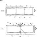
- Examples of configuration in which a single joint forming portion 12 is provided in the substrate 2 include an embodiment in which, as shown in FIG. 1, FIG. 2 and FIG. 6(b) , the joint forming portion 12 is provided in one position in the longitudinal direction L and extends throughout the length in the lateral direction S and an embodiment in which, as shown in FIG.7 , the joint forming portion 12 is provided in one position in the lateral direction S and extends throughout the length in the longitudinal direction L.
- Examples of configuration in which a plurality of joint forming portions 12 are provided in the substrate 2 include an embodiment in which, as shown in FIG. 6(a) , two joint forming portions 12 are arranged in the longitudinal direction L and each extend throughout the length in the lateral direction S.
- the disposing configuration of the joint forming portion 12 in the substrate 2 is not particularly limited; i.e. any disposing configuration may be adopted as long as the joint forming portion 12 can exhibit stress absorbing function. Although not shown, there may be adopted a configuration in which the separated substrate parts that are spaced apart in the longitudinal direction L and/or in the lateral direction S are intermittently connected by a plurality of joints 5.
- the joint forming portion 12 is comprised of the joint 5 which connects, to each other, the substrate parts 10 and 11 that are spaced apart from each other.
- the joint 5 has its both ends connected at connecting locations K to respective opposed surfaces of the substrate parts 10 and 11.
- the connecting locations K of the substrate parts 10 and 11 are linked in such a state that they are offset from each other in at least one of the longitudinal direction L, lateral direction S and thickness direction T. In the case of FIG.
- the connecting locations K are linked in such a state that they are offset from each other in the thickness direction T.
- the positions of the connection locations K are directly opposed to each other in the longitudinal direction L, lateral direction S and thickness direction T, and the joint 5 itself is a bent shaped body.
- Such a joint 5 that is capable of causing bending deflection is formed as a consequence of formation of groove-shaped recesses 6a and through hole recesses 6 in the joint forming portion 12.
- the joint 5 When the ends of the joint 5 are connected to respective substrate parts 10 and 11 in such a way that the positions of the connecting locations K of the opposed surfaces of the substrate parts 10 and 11 are offset from each other in the longitudinal direction L, lateral direction S or thickness direction T, or when the joint 5 itself is formed into a bent-shaped body in case where the positions of the connecting locations K are directly opposed to each other in the longitudinal direction L, lateral direction S and thickness direction T, the joint 5 can be easily bending-deformed.
- the substrate 2 is expanded or contracted as a result of a temperature change thereof or replacement of the gas within the cells thereof, the joint 5 is flexibly deformed to absorb the expansion or contraction. Therefore, it is possible to prevent the deformation such as warp of the long foam body even when the substrate 2 is expanded or contracted.
- the substrate parts 10 and 11 are connected to each other only by the joint and are not directly connected to each other.
- a through hole recess 6 that opens in the thickness direction is formed in a region which is within the range of the joint forming portion 12 and in which the joint 5 is not present in the lateral direction S.
- Embodiments of the joint 5 will be described by configuration of the connecting locations K of the joint 5 to substrate parts 10 and 11 on both sides thereof.
- the configuration of the joint 5 varies depending upon the thickness of the joint 5 relative to the substrate parts 10 and 11 and the positions of the connecting locations K in the longitudinal direction L, lateral direction S or thickness direction T.
- the thickness of the joint 5 is the same as that of the substrate parts 10 and 11 and the positions of the connecting locations K are offset in the thickness direction T.
- the joint 5 is formed by forming two groove-shaped recesses 6a that open oppositely in the thickness direction.
- the thickness of the joint 5 in the embodiments shown in FIG. 4 , FIG. 5 and FIG. 8 is the same as that of the substrate parts 10 and 11, while the thickness of the joint 5 in the embodiments shown in FIG. 9 to FIG. 11 is thinner than that of the substrate parts 10 and 11 and differs therefrom.
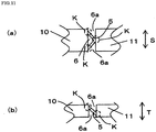
- FIG. 4 Examples of the configuration of the joint 5 in which the thickness of the joint 5 is the same as that of the substrate parts 10 and 11 and the connecting locations K are offset from each other in the longitudinal direction L or lateral direction S are shown in FIG. 4 , FIG. 8(a) and FIG. 8(c) .
- the connecting locations K are offset in the lateral direction S, and groove-shaped recesses 6a that open in the side surfaces are formed on both sides of the joint 5.
- the joint 5 shown in FIG. 4 is deformed in the lateral direction S.
- the connecting locations K are offset in the lateral direction S, and groove-shaped recesses 6a are formed on both sides.
- the configuration of the joint 5 in the present invention is not limited to the above examples only. Any configuration may be adopted as long as the joint can be bending-deformed in the longitudinal direction and/or lateral direction so as to permit the substrate parts 10 and 11 to displace relative to each other either in the mutually departing direction when the substrate 2 contracts or in the mutually approaching direction when the substrate expands.
- FIG. 5 examples of the configuration of the joint 5 in which the thickness of the joint 5 is the same as that of the substrate parts 10 and 11 and the connecting locations K are directly opposed to each other in the longitudinal direction L, lateral direction S and thickness direction T are shown in FIG. 5 and FIG. 8(b) .
- the positions of the connecting locations K are aligned in the longitudinal direction L, lateral direction S and thickness direction T, and the joint is formed with a bent portion and is nearly U-shaped as seen in plan view. Additionally, groove-shaped recesses 6a are formed on both sides.
- FIG. 5 examples of the configuration of the joint 5 in which the thickness of the joint 5 is the same as that of the substrate parts 10 and 11 and the connecting locations K are directly opposed to each other in the longitudinal direction L, lateral direction S and thickness direction T are shown in FIG. 5 and FIG. 8(b) .
- the positions of the connecting locations K are aligned in the longitudinal direction L, lateral direction S and thickness direction T, and the joint is formed with a bent portion and is nearly U-shaped
- the positions of the connecting locations K are aligned in the longitudinal direction L, lateral direction S and thickness direction T and the joint is formed with a bent portion an is nearly V-shaped as seen in plan view. Additionally, groove-shaped recesses 6a are formed on both sides. These configurations are merely examples. It is sufficient that the joint 5 is configured to be able to be bending-deformed in the longitudinal direction and/or lateral direction to permit the substrate parts 10 and 11 to displace relative to each other.
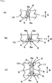
- FIG. 10 and FIG. 11 examples of the configuration of the joint 5 in which the thickness of the joint 5 differs from that of the substrate parts 10 and 11 and the connecting locations K are offset from each other in the longitudinal direction L, lateral direction S or thickness direction T are shown in FIG. 10 and FIG. 11 .
- the thickness of the joint 5 is thinner than that of the substrate parts 10 and 11.
- the connecting locations K are offset from each other in the lateral direction S and thickness direction T and groove-shaped recesses 6a are formed on both sides.
- the thickness of the joint 5 is thinner than that of the substrate parts 10 and 11, and the connecting locations K are offset from each other in the lateral direction S and thickness direction T.
- connecting locations K are provided in the substrate part 10, while only one connecting location K is provided in the substrate part 11, so that the joint 5 is nearly V-shaped as seen in plan view. Further, the connecting locations K are offset from each other in the lateral direction S and thickness direction T and groove-shaped recesses 6a and a through-hole recess 6 are formed. These configurations are merely examples. It is sufficient that the joint 5 is configured to be able to be bending-deformed in the longitudinal direction and/or lateral direction to permit the substrate parts 10 and 11 to displace relative to each other.
- FIG.9 an example of the configuration of the joint 5 in which the thickness of the joint 5 differs from that of the substrate parts 10 and 11 and the connecting locations K are directly opposed to each other in the longitudinal direction L, lateral direction S and thickness direction T is shown in FIG.9 .
- the thickness of the joint 5 is made thinner than that of the substrate parts 10 and 11.
- the connecting locations K are directly opposed in the longitudinal direction L, lateral direction S and thickness direction T.
- the joint is formed with a bent portion and is nearly V-shaped as seen in plan view. Additionally, groove-shaped recesses 6a are formed on both sides. These configurations are merely examples.
- the joint 5 is configured to be able to be bending-deformed in the longitudinal direction and/or lateral direction to permit the substrate parts 10 and 11 to displace relative to each other.
- the number of the joint 5 is not limited to one as in the embodiments of FIG. 9 to FIG. 11 .
- a plural number of the joints 5 may be formed in the lateral direction S and/or thickness direction T.
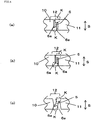
- FIG. 4(a) and FIG. 5(a) each show a configuration of the substrate parts 10 and 11 and the joint 5 in an as designed state
- FIG. 4(b) and FIG. 5(b) each show the joint 5 in a bending-deformed state when the substrate parts 10 and 11 are expanded in their dimensions
- FIG. 4(c) and FIG. 5(c) each show the joint 5 in a bending-deformed state when the substrate parts 10 and 11 are contracted in their dimensions.
- the substrate parts 10 and 11 and the joint 5 of the joint forming portion 12 may be integrally formed together by subjecting the thermoplastic resin expanded beads to in-mold molding.
- a pair of openable and closable male and female molds configured, when in a closed position, to form a mold cavity consistent in shape with the substrate 2 which has a desired shape and is provided with a joint 5 having a predetermined shape at a predetermined position may be used to simultaneously and integrally form the substrate parts 10 and 11 and the joint 5.
- the frame 3 may be inserted into the mold cavity when the above in-mold molding is carried out so that the long synthetic resin foam 1 is produced in one step.
- the joint 5 may be formed, after the substrate 2 has been produced by in-mold molding, by forming through hole-recesses 6 and groove-shaped recesses 6a at desired positions using a cutter and a grinder, thereby to form the joint forming portion 12 in the substrate 2.
- the width of the recesses 6 and 6a is preferably made the same as or greater than the maximum dimension of the predicted dimensional variation at the time of in-mold molding from the standpoint of workability in the case of fitting the frame 3 into the substrate 2 and of relaxing a dimensional change by shrinkage of the substrate 2 after insert molding in the case of integral molding of the substrate 2 and frame 3. More specifically, it is preferred that the width of the recesses 6 and 6a in the direction parallel with the connecting section 23 of the frame 3 is 3 mm to 70 mm, more preferably 5 mm to 50 mm, particularly 10 mm to 25 mm.
- the long foam body 1 constituted of a synthetic resin foam body may be provided with a plurality of the joint forming portions 12, the width of the recesses 6 and 6a may be proportionally distributed according to the number of the recesses. It is more desirable that those portions of the joint 5 which define the peripheral edges of the recesses 6 and 6a and the corner portions of substrate parts 10 and 11 be rounded (formed with "R") for reasons of avoiding the concentration of stress.
- the long synthetic resin foam body of the present invention is suited as a rear seat core material for vehicles such as a seat back core material and a seat cushion core material.
- the widthwise direction of the vehicle is "the longitudinal direction” thereof
- the front to rear direction of the vehicle is “the lateral direction”
- the direction normal to the widthwise direction of the vehicle and to the front to rear direction of the vehicle is "the thickness direction”.
- the widthwise direction of the vehicle is “the longitudinal direction” thereof
- the up-down direction of the seat back of the vehicle is “the lateral direction”
- the direction normal to the widthwise direction of the vehicle and to the up-down direction of the seat back of the vehicle is “the thickness direction”.
- a rear seat back to be mounted on an automobile is assumed as a foam body in the present example.
- a polypropylene resin expanded beads-molded body having a density of 0.03 g/cm 3 as a substrate, a long synthetic resin foam body having a length, in the widthwise direction of the vehicle when mounted, of 1,300 mm, a width of 450 mm and a thickness of 80 mm was obtained.
- a groove 4 was formed in the substrate at a position 50 mm inward from the both side edges.
- a rectangular annular frame made of a stainless hollow pipe having a diameter of 10 mm was closely fitted in the groove at an ambient temperature.
- test specimens having dimensional variations in the longitudinal direction L of ⁇ 0mm, +10mm, -10mm were prepared as imitation of dimensional variation at the time of molding of real polypropylene resin expanded beads substrates by volume production.
- two groove-shaped recesses 6a which extended oppositely in the thickness direction and each of which had a width of 5 mm and a depth of 65 mm were formed in each specimen at a middle portion in the longitudinal direction thereof to provide each specimen with the joint-forming portion 12.
- test piece having a length of 350 mm, a width of 100 mm and a thickness of 25 mm and containing no skin was cut out and subjected to a three point bending test according to JIS K7221-2 (2006) in the atmosphere of 23° ⁇ 2°C and a relative humidity of 50 ⁇ 5% using an inter-fulcrum distance of 300 mm and a test speed of 20 ⁇ 1 mm/min, thereby obtaining a load deflection curve.
- the test piece showed a deflection of over 100 mm (specimen was not broken even at a deflection of 100 mm or more) and a load of 26 N at the 20 mm deflection.
- Each of the test specimens was provided with the groove 4 having the same width as that of the frame to be fitted thereinto.
- a worker was able to be fit the frame 3 into the groove 4 of the specimen by applying thereto such a force as to stretch the specimen in the case of the test specimen having a short length (-10 mm) and to press the frame toward the joint forming portion 12 in the case of the test specimen having a long length (+10 mm).
- the length of each of the +10 mm and -10 mm specimens was changed to the standard dimension. Namely, dimensional variation at the time of the preparation of the long expanded beads-molded bodies was able to be absorbed at ambient temperature.
- test specimens that imitated a seat back were each allowed to stand in an environment at 80°C and -30°C for a given period of time to observe changes of their dimensions by the temperature changes.
- expansion and contraction of about ⁇ 8 mm were observed at 80°C and -30°C, respectively. This value is considered to increase by ⁇ 10 mm when dimensional variation in molding of expanded beads-molded substrate by volume production is assumed. If such an increased dimensional difference is caused, there is a possibility that the foamed body itself will be deformed due to formation of a gap or due to interaction between it and an adjacent foam body.
- the long foam bodies of the present invention which were each constituted of the expanded beads-molded substrate 2 provided with the joint forming portion 12, the groove 4 and the frame closely fitted into the groove without gaps, the frames were found to restrict the expansion and contraction of the expanded beads-molded substrates notwithstanding the fact that the substrates had dimensions of standard dimension, +10 mm and -10 mm before having been fitted with the iron frames. Namely, the foam bodies were able to have the dimensions as designed. Further, expansion and contraction due to the temperature changes were found to be not greater than ⁇ 3 mm. The long foam bodies of the present invention surely showed sufficient dimensional stability.
- a core material for a rear seat cushion to be mounted on an automobile is assumed as a part in this example.
- a mold tool having a shape of the foam part composed of two spaced apart substrate parts separated in the longitudinal direction as shown in FIG. 1 was provided.
- a wire frame that was made of an iron wire material and had a roughly rectangular annular shape, a diameter of 4.5 mm and a tensile strength (JIS G3532 SWM-B) of 500 N/mm 2 was inserted as the frame into the mold tool and supported therein. Subsequently, the mold tool was closed.
- polypropylene-based resin expanded beads having a bulk density of 0.03 g/cm 3 and a bead diameter of about 4 mm were filled in the mold tool.
- in-mold molding was carried out by heating the inside the mold tool with steam.
- the heating method was as follows. Steam was fed for 5 seconds for preheating (air purging step) while maintaining drain valves on both side molds in an open state. One-direction heating was then carried out with a molding steam pressure of 0.22 MPa(G) and another one-direction heating was carried out in the opposite direction with a molding steam pressure of 0.04 MPa(G). Subsequently, full heating was carried out at a molding steam pressure of 0.3 MPa(G) from both sides.
- the pressure was released and air cooling was carried out for 30 seconds. Then, water cooling was carried out for 240 seconds to obtain a polypropylene-based resin expanded beads-molded body having the frame integrally molded along the periphery of the expanded beads-molded body.
- the obtained expanded-beads-molded body was thereafter dried and aged in the atmosphere of 60° C for 24 hours, thereby obtaining a long foam body which had a length of 1,300 mm, a width of 450 mm and a thickness of 100 to 150 mm and which was formed of two bisected substrate parts that were spaced apart in the longitudinal direction and connected to each other by joints formed in two locations.
- the joints of a joint forming portion had a shape as shown in FIG.
- groove-shaped recess 6a had a width of 10 mm and a depth of 80 mm) and provided at two locations in the lateral direction so as to cover the connecting sections of the insert-molded frame.
- the frame was embedded in the expanded beads-molded body at a position spaced inside from the peripheral edge of the substrate by a distance of 50 mm and also spaced in the thickness direction from the bottom face of the molded body by a distance of 50 mm.
- the expanded beads-molded body was formed in a sloped shape such that the thickness thereof was 150 mm at its one end which corresponded to the front end when used as the core material of the rear seat cushion, and 100 mm at its another end which corresponded to the rear end.
- a test piece having a length of 350 mm, a width of 100 mm and a thickness of 25 mm and containing no skin was cut out and subjected to a three point bending test according to JIS K7221-2 (2006) in the atmosphere of 23° ⁇ 2°C and a relative humidity of 50 ⁇ 5% using an inter-fulcrum distance of 300 mm and a test speed of 20 ⁇ 1 mm/min, thereby obtaining a load deflection curve.
- the test piece showed a deflection of 100 mm or more (specimen was not broken even at a deflection over 100 mm) and a load of 26 N at the 20 mm deflection.
- the distance between the two substrate parts in a spaced apart state was widened by a length of 15 mm at its joint forming portion as compared with the dimension of the mold.
- the long foam body also showed an upward warp of 3 mm.
- a comparative long foam body which was the same as above except for being provided with no joint forming portion was found to show an upward warp of 10 mm when subjected to the similar measurement.
- the obtained long foam body was allowed to stand in an atmosphere at 80°C and -30°C for a given period of time to observe changes of their dimensions by the temperature changes.
- the long foam body of the example according to the present invention showed expansion and contraction of about ⁇ 3 mm or less in the above temperature change.
- a comparative long foam body which was the same as above except for being provided with no joint forming portion was found to show expansion and contraction of about ⁇ 8 mm in the above temperature change.
- the long foam body of the present invention showed suppressed dimensional change by temperature change and suppressed rise of the bottom face by warpage after in-mold molding and, therefore, showed sufficient dimensional stability.
Landscapes
- Engineering & Computer Science (AREA)
- Manufacturing & Machinery (AREA)
- Aviation & Aerospace Engineering (AREA)
- Transportation (AREA)
- Mechanical Engineering (AREA)
- Buffer Packaging (AREA)
- Mattresses And Other Support Structures For Chairs And Beds (AREA)
- Manufacture Of Porous Articles, And Recovery And Treatment Of Waste Products (AREA)
Abstract
Description
- The present invention relates to a long synthetic resin foam body and, more specifically, to a long length thermoplastic resin foam body usable for many purposes and exhibiting excellent dimensional stability irrespective of whether it is under high temperature or low temperature conditions.
- Molded articles of synthetic resin foam bodies generally have a light weight and flexibility and yet show a certain level of rigidity and excellent shock absorbing property and, therefore, are extensively used in a wide variety of fields such as automobile parts, packaging materials and household miscellaneous goods. Synthetic resin foam bodies are, however, generally formed from innumerable cells in the form of closed cells of the resin containing a large amount of air or a gas. Therefore, the foam bodies have a high linear expansion coefficient and greatly expand or contract when subjected to environmental temperature changes. Thus, a problem that the dimensional change is great is caused particularly when the foam body is a long length part, although a dimensional change is not problematic in the case of a small-sized part in which an amount of the dimensional change is small.
- Among synthetic resin foam bodies, a thermoplastic resin expanded beads-molded body, which can be easily molded into a desired shape, may be obtained by filling the expanded beads in a mold, then heating the expanded beads with, for example, steam, to fusion-bond them. After cooling, the foam body is taken out from the mold. Such a molded article formed of an expanded beads-molded article body has encountered a problem that a large dimensional variation of the molded article is liable to be caused as compared with other resin parts even by a small variation of the expansion ratio of the expanded beads, the temperature and pressure of steam, temperature of cooling water, mold tool and temperature of the atmosphere into which the molded product is taken out of the mold. Especially when the molded article is a long length expanded beads-molded body, there are caused problems in assembling to another part such as formation of a practically undesirable gap and deformation thereof by interference with another part, because not only expansion and contraction by an environment temperature change but also variation of dimensions at the time of molding is apt to occur.
- In this circumstance, in order to ensure dimensional accuracy of an elongated part of a synthetic resin foam body, there has been adopted, although reluctantly, as a first method, a measure in which cut finishing is carried out as post processing or a measure of dividing into a plural parts to avoid production of an elongated body.
- As a second method, there is a method to suppress expansion and contraction of a molded article of an expanded beads-molded body. In this method, a material having a small linear expansion coefficient and rigidity, such as a metal wire frame, is previously set in a mold and then thermoplastic resin expanded beads are filled in the mold. The wire frame is subjected to insert molding and is thus employed also for the purpose of adding means to function as a reinforcement and a mounting part. Such a method is partially used in a part such as a sun visor or a rear seat of an automobile for the purpose of decreasing the weight thereof. Since expansion and contraction by a temperature change of an expanded beads-molded body that is surrounded by and positioned inside a frame made of a material showing a low tendency to expand and contract by a temperature change, such as a metal wire frame, are forcibly suppressed by the frame, a dimensional change of the part made of the expanded beads-molded body as a whole is only ascribed to the expansion and contraction of that portion of the synthetic resin foam body which is located outside the region surrounded by the frame. Therefore, the part as a whole shows good dimensional stability.
-
Patent Document 1 discloses an automobile interior ceiling forming body which has a seven-layered structure having a foamed polypropylene sheet laminated, on its both sides, with a glass fiber sheet laminate structural body that is composed of a glass fiber sheet and a polypropylene sheet laminated on each of the both sides of the glass fiber sheet. This technique intends to ensure a dimensional accuracy by use of the glass fiber. - Patent document 1: Japanese Laid Open Patent Publication No.
JP-A-2003-34192 - In the case of the first method, there is a problem because the method causes cost up due to the post processing and division and because the method has to be limited to application to the case that permits post processing or division, as is seen in the case of an elongated part formed of a synthetic resin in-mold molded body, such as a nap bed for trucks, a one piece-type seat back for a rear seat of automobiles and a cushioning material for furniture.
- The second method encounters a problem in the case where the strength of the wire frame is set to such a range of the bending strength and tensile strength as to achieve the primary objects of use thereof as well as to achieve the reduction of the weight or in the case where the shape or mounting position thereof has an offset. Namely, when a long part is to be produced, the expanded beads-molded body cannot withstand a temporal strong contraction force exerted when it is taken out from the mold and is brought into contact with outside air immediately after the in-mold molding and, therefore, deformation such as warp occurs in the whole region of the synthetic resin in-mold molded body and remains disappear.
- The invention of
Patent Document 1 has a problem because the manufacturing costs are high for reasons that the structure of the polypropylene foam laminate is complicated. Additionally, the laminate is suited for use as an automobile interior ceiling member but is not suited for use as a one piece-type seat back for a rear seat of automobiles or as a heat insulating material for being embedded between columns of a house. - Thus, it is an object of the present invention to provide a long length synthetic resin foam body which is suited for use as a core material of a seat back or seat cushion of a rear seat of automobiles, a furniture, a nap bed for trucks, etc., which is light in weight and which ensures excellent dimensional accuracy.
- The gist of the present invention pertaining to a
long part 1 formed of a synthetic resin foam body is as follows: - (1) A long synthetic resin foam body comprising:
- a thermoplastic resin expanded beads-molded substrate that has a longitudinal direction, a lateral direction and a thickness direction, and
- a frame that has a pair of displacement regulating sections which are longitudinally or laterally spaced apart from each other and provided in said substrate at positions spaced inward from opposing longitudinal or lateral ends of said substrate and at least one connecting section which connects the paired displacement regulating sections to each other,
- said substrate having at least one joint forming portion that divides said substrate in a direction intersecting the connecting section into two or more substrate parts,
- said joint forming portion having at least one joint that connects adjacent two substrate parts to each other, and
- said joint being deformable to permit a relative displacement between the adjacent two substrate parts when said substrate contracts or expands;
- (2) The long synthetic resin foam body as recited in above (1), wherein said joint has one end connected to one of adjacent two substrate parts at a first connecting location and the other end connected to the other one of the substrate parts at a second connecting location which is offset from said first connecting location in the longitudinal direction, lateral direction and/or thickness direction;
- (3) The long synthetic resin foam body as recited in above (1), wherein said joint has a curved or bent shape and has one end connected to a first substrate part at a first connecting location and the other end connected to a second substrate part at a second connecting location which aligns with said first connecting location in all of the longitudinal direction, lateral direction and thickness direction;
- (4) The long synthetic resin foam body as recited in any one of above (1) to (3), wherein each of said displacement regulating sections is in closely fitting engagement with said substrate;
- (5) The long synthetic resin foam body as recited in any one of above (1) to (3), wherein said substrate has a pair of laterally extending grooves provided adjacent to both longitudinal ends of said substrate and said displacement regulating sections are in the form of plates closely fitting engagement in said grooves;
- (6) The long synthetic resin foam body as recited any one of above (1) to (3), wherein said substrate has a pair of protrusions provided adjacent to both longitudinal ends of said substrate and said displacement regulating sections are in the form recesses that are in closely fitting engagement with said protrusions;
- (7) The long synthetic resin foam body as recited in any one of above (1) to (3), wherein said substrate has a pair of holes provided adjacent to each of both longitudinal ends of said substrate and said displacement regulating sections are in the form of protrusions closely fitting engagement with said holes;
- (8) The long synthetic resin foam body as recited in any one of above (1) to (5), wherein said frame has an annular structure in which said paired displacement regulating sections are connected at their ends by a pair of the connecting sections;
- (9) The long synthetic resin foam body as recited in any one of above (1) to (8), wherein the thermoplastic resin expanded beads are polyolefin-based resin expanded beads;
- (10) The long synthetic resin foam body as recited in any one of above (1) to (8), wherein the thermoplastic resin expanded beads are expanded beads of a base resin that is a composite resin of a polyolefin-based resin and a polystyrene-based resin;
- (11) The long synthetic resin foam body as recited in any one of above (1) to (10), wherein the thermoplastic resin expanded beads have a bending deflection of 20 mm or more and a load of 2 to 100 N at bending deflection of 20 mm, both of which are measured by a bending test method according to JIS K7221-2 (2006);
- (12) The long synthetic resin foam body as recited in any one of above (1) to (5), wherein said frame is an annular metal wire frame having first two opposed frame sections serving as said displacement regulating sections and second two opposed frame sections that connect the first two opposed frame sections to each other and that serve as said connecting sections; and
- (13) The long synthetic resin foam body as recited in any one of above (1) to (3), wherein said frame is integrally embedded in said substrate by insert molding.
- The long synthetic resin foam body recited in above (1) to (3) can effectively suppress a dimensional variation during the in-mold molding of the thermoplastic resin expanded beads-molded substrate as well as the expansion and contraction thereof by a temperature change after the in-mold molding.
- The long foamed body of the synthetic resin foam body recited in above (4) permits easy removal of the frame fitted therein and easy disintegration thereof into respective components for recycling.
- The invention recited in above (5) to (7) is embodied in various forms of the frame and long foam body substrate which is formed of a synthetic resin foam body whose longitudinal dimension is apt to vary. The invention shows an effect that it is applicable even when the object and mode of use of the long foam body are varied.
- The invention as recited in in above (8) in which an annular frame is used can achieve both excellent dimensional stability and lightness in weight.
- The invention recited in above (9) and (10) provides preferred embodiments of the thermoplastic resin expanded beads-molded body that constitutes the substrate.
- The invention recited in above (11) provides particularly preferred embodiment of the thermoplastic resin expanded beads-molded body that constitutes the substrate.
- The invention recited in above (12) provides particularly preferred embodiment among the exemplified frames.
- In the long synthetic resin foam body recited in above (13) in which the frame and substrate are integrally molded in a mold by insert molding, the frame can be firmly fixed in the substrate. Additionally, as compared with a case in which the frame is in fitting engagement with the substrate, it is possible to reduce the process steps for obtaining the long foam body of the present invention.
-
-
FIG. 1 is an illustration of one embodiment of the long foam body of the present invention that uses a substrate separated into two in the longitudinal direction, in which (a) is a plan view and (b) is a cross-sectional view taken along A-A in (a). -
FIG. 2 is an illustration of a substrate used in the long foam body ofFIG. 1 , in which (a) is a plan view, (b) is a cross-sectional view taken along B-B in (a) and (c) is a front view. -
FIG. 3 is an explanatory view of an embodiment of a frame used in the long foam body ofFIG. 1 , in which (a) is a plan view, (b) is a front view and (c) is a plan view of a frame of another embodiment. -
FIG. 4 is a partial enlarged front view explanatory of bending deformation of a joint that connects two substrate parts of a long foam body of the present invention, in which (a) is an illustration showing a non-load state, (b) is an illustration showing the bending deformation of the joint at a time when the two substrate parts are relatively displaced in the mutually approaching direction as a result of longitudinal extension of the substrate and (c) is an illustration showing the bending deformation of the joint at a time when the two substrate parts are relatively displaced in a mutually departing direction as a result of shrinkage of the substrate. -
FIG. 5 is a partial enlarged front view showing a joint that connects two substrate parts of a long foam body according to another embodiment of the present invention, in which (a) is an illustration showing a non-load state, (b) is an illustration showing the bending deformation of the joint at a time when the two substrate parts are relatively displaced in the mutually approaching direction as a result of longitudinal extension of the substrate and (c) is an illustration showing the bending deformation of the joint at a time when the two substrate parts are relatively displaced in a mutually departing direction as a result of shrinkage of the substrate. -
FIG. 6 is an illustration showing another embodiment of the long foam body of the present invention, in which (a) is a plan view showing an embodiment provided with joint forming portions in two positions in the longitudinal direction and (b) is a view illustrating an embodiment provided with two joints at opposite end portions in the lateral direction of the substrate that is separated into two in the longitudinal direction. -
FIG. 7 is an illustration showing another embodiment of the long foam body of the present invention that is composed of a substrate separated into two in the lateral direction and an annular frame, in which (a) is a plan view and (b) is a cross-sectional view taken along A-A in (a). -
FIG. 8 is an explanatory plan view showing various embodiments of a joint having the same thickness as that of the substrate, in which (a) shows a Z-shaped joint, (b) shows a V-shaped joint and (c) shows an X-shaped joint. -
FIG. 9 is an explanatory plan view showing an embodiment of a joint having a different thickness from that of the substrate, in which (a) is a plan view and (b) is a front view. -
FIG. 10 is an explanatory plan view showing another embodiment of a joint having a different thickness from that of the substrate, in which (a) is a plan view and (b) is a front view. -
FIG. 11 is an explanatory plan view showing a further embodiment of a joint having a different thickness from that of the substrate, in which (a) is a plan view and (b) is a front view. -
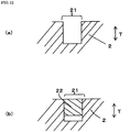
FIG. 12 is an illustration explanatory of a fitting-engagement state between a groove provided in the substrate ofFIG. 2 and a displacement regulating section of the frame ofFIG. 3 , in which (a) is a sectional view of the groove of the substrate at a portion D inFIG.2(b) and (b) is a sectional view showing a fitting-engagement state between the displacement regulating section inFIG. 3(a) and the groove of the substrate ofFIG. 1(b) at a portion C. -
FIG. 13 is an illustration of another embodiment of the long foam body of the present invention that uses a substrate separated into two in the longitudinal direction, in which (a) is a plan view and (b) is a cross-sectional view taken along C-C in (a). -
FIG. 14 is an illustration of a substrate used in the long foam body ofFIG. 13 , in which (a) is a plan view and (b) is a cross-sectional view taken along D-D in (a). -
FIG. 15 is an illustration of a frame used in the long foam body ofFIG. 13 , in which (a) is a plan view and (b) is a cross-sectional view taken along E-E in (a). -
FIG. 16 is an illustration of another embodiment of the long foam body of the present invention that uses a substrate separated into two in the longitudinal direction, in which (a) is a plan view, (b) is a side view and (c) is a cross-sectional view taken along F-F in (a). -
FIG. 17 is an illustration of a substrate used in the long foam body ofFIG. 16 , in which (a) is a plan view and (b) is a cross-sectional view taken along G-G in (a). -
FIG. 18 is an explanatory view of the frame used in the long foam body ofFIG. 16 , in which (a) is a plan view, (b) is a cross-sectional view taken along H-H in (a). - Referring to
FIG.1 to FIG. 18 , a long syntheticresin foam body 1 according to the present invention is comprised of a thermoplastic resin expanded beads-substrate 2 that has a longitudinal direction L, a lateral direction S and a thickness direction T, which directions are orthogonal to each other. Incidentally, the long foam body of the present invention generally has a dimension in the longitudinal direction L which is 650 mm or more and a generally rectangular shape as seen in plan view. The syntheticresin foam body 1 preferably has a bending deflection of 20 mm or more and a load of 2 to 100 N at bending deflection of 20 mm, both of which are measured by a bending test method according to JIS K7221-2 (2006). More preferably, the bending deflection is 50 mm or more and the load of 10 to 50 N at bending deflection of 20 mm. The bending test according to JIS K7221-2 (2006) uses a method in which a test piece having a length of 350 mm, a width of 100 mm and a thickness of 25 mm is used to obtain a load-deflection curve in the atmosphere of 23°C±2°C and a relative humidity of 50±5% under loading conditions involving an inter-fulcrum distance of 300 mm and a test speed of 20±1 mm/min. Thelong foam body 1 is further comprised of aframe 3 that has a pair ofdisplacement regulating sections 22 provided in both end portions in the longitudinal or lateral direction of thesubstrate 2 and a connectingsection 23 that connects thedisplacement regulating sections 22 to each other. Thesubstrate 2 has at least one joint formingportion 12 that divides the substrate in a direction intersecting the connectingsection 23 into two ormore substrate parts portion 12 serves to function as a stress absorbing section of thesubstrate 2 and has at least one joint 5 that connects adjacent two spaced apartsubstrate parts substrate parts substrate 2 contracts or expands. Because the joint 5 is made deformable, thesubstrate parts substrate 2 in the longitudinal direction, etc. is stabilized and maintained at a value in a constant range. - In a preferred embodiment, the joint has one end connected to one of adjacent two spaced apart
substrate parts 10 at a first connecting location K and the other end connected to the other one of thesubstrate parts 11 at a second connecting location K which is offset from said first connecting location in the longitudinal direction, lateral direction and/or thickness direction. In another preferred embodiment, the joint 5 has a curved or bent shape and has one end connected to one of adjacent two spaced apartsubstrate parts 10 at a first connecting location and the other end connected to the other one of thesubstrate parts 11 at a second connecting location which aligns with the first connecting location in all of the longitudinal direction, lateral direction and thickness direction. Thus, the first connecting location and the second connecting location are directly opposed to each other. Because the joint 5 is thus configured to be deformable, the adjacent twosubstrate parts substrate 2 in the longitudinal direction and/or lateral direction may be stabilized and maintained at a value in a certain range. Incidentally, as shown inFIG. 7 , theframe 3 may be embedded in thesubstrate 2 by insert molding and integrally provided in thesubstrate 2. Further, as shown inFIG. 7 , thesubstrate parts substrate parts joints 5 that are formed discontinuously. - The present invention is characterized first in that a thermoplastic resin expanded beads-molded
substrate 2 is separated intosubstrate parts portion 12, with these substrate parts being connected to each other by a joint 5 of the joint formingportion 12 so as to be flexibly displaceable relative to each other when subjected to compression or stretching in the longitudinal direction L or lateral direction S, and second in thatdisplacement regulating sections 22 of aframe 3 having rigidity, such as wire, pipe or plate, are integrated with thesubstrate 2 by being fitted in thesubstrate 2 or by being insert molded in thesubstrate 2. As a result of these features, the dimensions in the longitudinal direction and/or lateral direction of the long syntheticresin foam body 1 of the present invention are stabilized. - The long synthetic
resin foam body 1 is comprised of the thermoplastic resin expanded beads-moldedsubstrate 2. The synthetic resin expanded beads are a material composed of cells containing a large amount of air or a gas. Therefore, the dimensions of the expanded beads-molded body are liable to vary by a great number of factors such as a steam temperature or pressure, a cooling water temperature, a difference in a molding device used in in-mold molding, a temperature of the outside atmosphere and a variation of the expansion ratio of the raw material expanded beads. For example, in the case of a polypropylene expanded beads-molded body, a dimensional variation of about ±0.7 to 1.2% is generally caused in the product dimensions. Such a variation corresponds to about ±10 mm in the case of an expanded beads-molded substrate having a length of 1,000 mm. Therefore, when aframe 3 is fitted into a groove of an expanded beads-molded substrate, for example, it is practically impossible to form the groove of the expanded beads-molded substrate produced by in-mold molding at a precise position and in precise dimensions, even when a section for forming the groove into which adisplacement regulating section 22 of theframe 3 is to be fitted is designed on the mold. Further, though the expanded beads-molded substrate used in the present invention has flexibility, it also has a certain degree of rigidity. Therefore, it is impossible for a worker to closely fit a rigid body such as a frame into the groove of the substrate that has a variation of ±10mm in its dimensions. When an insert molding method is adopted to embed theframe 3 within the expanded beads-molded substrate, on the other hand, theframe 3 is unable to withstand a high contraction force of the expanded beads-molded substrate and deforms after completion of the in-mold molding. Thus, there is caused a phenomenon that deformation such as warp occurs in the entire expanded beads-molded substrate and remains disappear. - The long synthetic
resin foam body 1 of the present invention has a structure which ensures dimensional accuracy in spite of using a substrate having such a property that the dimensional accuracy is apt to vary. - Description will be first made of the
substrate 2. Thesubstrate 2 is formed of a thermoplastic resin expanded beads-molded body and is, for example, a long foam body as shown inFIG. 1 and FIG. 2 that has a longitudinal direction L and a lateral direction S as seen in plan view. It is preferred that thesubstrate 2 has a bending deflection of 20 mm or more and a load of 2 to 100 N at bending deflection of 20 mm, both of which are measured by a bending test method according to JIS K7221-2 (2006). - The thermoplastic resin expanded beads-molded
substrate 2 of the present invention may be formed by filling thermoplastic resin expanded beads in a mold and, thereafter, heating the expanded beads with a heating medium such as steam to fusion-bond the expanded beads to each other into an unitary body. More specifically, thesubstrate 2 is a thermoplastic resin expanded beads-molded substrate that is formed of, as a base resin, a polyolefin-based resin such as polypropylene and polyethylene; a polystyrene-based resin; or a composite resin (modified polystyrene resin) of a polyolefin-based resin and a polystyrene-based resin. A material which easily causes breakage or irreversible deformation by bending deformation is not suitable. The expanded beads-moldedsubstrate 2 preferably has a density of 0.015 to 0.3 g/cm3, more preferably 0.02 to 0.2 g/cm3, particularly preferably 0.025 to 0.1 g/cm3. The density of the expanded beads-moldedsubstrate 2 herein is as calculated by dividing the mass of the substrate by the volume thereof. - Further, the
substrate 2 is composed ofsubstrate parts portion 12 which connects thesubstrate parts substrate 2 is divided by at least one joint formingportion 12 into two or more substrate parts. For the purpose of simplifying the explanation, the following description will be primarily made on thesubstrate 2 which is divided into twosubstrate parts portion 12. Thesubstrate parts portion 12. It is preferred that thesubstrate parts joint 5 of the joint formingportion 12 and that there is no portion in which the adjacent twosubstrate parts substrate parts substrate 2 will not be able be absorbed and there will be brought about variation in dimensional accuracy of along foam body 1 constituted of such expanded beads-moldedsubstrate 2. - When the
frame 3 is in fitting engagement with thelong substrate 2, thesubstrate 2 is formed with a fitting-engagement portion 21, into which thedisplacement regulating section 22 of theframe 3 is fittable, at each of the both longitudinal end portions or both lateral end portions of thesubstrate 2. The fitting-engagement portion 21 of thesubstrate 2 may be embodied, for example, in the form of a groove as shown inFIG. 2 , in the form of holes as shown inFIG. 14 or in the form of protrusions as shown inFIG. 17 . - When the fitting-
engagement portion 21 of thesubstrate 2 is a groove, the configuration thereof is determined as appropriate depending upon the configuration of theframe 3. For example, when theframe 3 is an annular shape as shown inFIG. 3(a) , grooves, which extend in the lateral direction and configured to be fittingly engaged withdisplacement regulating sections 22 of theframe 3, are formed at both end portions, in the longitudinal direction L, of thesubstrate 2 in the state as shown inFIG. 2(a) in a plan view, inFIG. 2(b) in a cross-sectional view taken along B-B and inFIG. 2(c) in a front view and, additionally, longitudinal grooves which are configured to be fittingly engaged with connectingsections 23 of theframe 3 are formed, so that an annular groove 4 (FIG. 2(a) ) is formed as a whole. When the connectingsection 23 of theframe 3 is single as shown inFIG. 3(c) , thegroove 4 is H-shaped as a whole. Incidentally, thegroove 4 may be formed on a top side of thesubstrate 2 or on a bottom side thereof. - It is important that that portion of the synthetic resin foam body in the fitting-
engagement portion 21 which is to be located adjacent to an outer or inner side of thedisplacement regulating section 22, namely the periphery of the groove into which thedisplacement regulating section 22 is brought into fitting engagement must have a sufficient rigidity. Namely, it is necessary that the periphery of the fitting-engagement portion should have a rigidity sufficient to withstand a restraint force exerted from thedisplacement regulating section 22 fitted therein at a time the expanded beads-substrate 2 expands or contracts when subjected to under a high or low temperature. If the periphery of the fitting-engagement portion does not have a sufficient rigidity, the periphery of the groove will be damaged or deformed when the expanded beads-molded body expands or contracts, thereby to cause disengagement of theframe 3 and inhibition of the effect of prevention of expansion or contraction of the expanded beads-molded body. It is, therefore, preferred that the thickness of the substrate at the outside and inside of the fitting-engagement portion is 8 mm or more, more preferably 15 mm or more, though the thickness depends on the shape and physical properties of thelong foam body 1 and the shape and position of theframe 3. - When the fitting-
engagement portion 21 of the substrate is in the form of holes, such holes are formed, for example, at both end portions in the longitudinal direction L of thesubstrate 2 in the state as shown inFIG. 14(a) in a plan view and inFIG. 14(b) in a cross-sectional view taken along D-D. The length in the lateral direction S of the holes and the number thereof may be determined such that the contact area, established when the protrusion-shapedisplacement regulating sections 22 of theframe 3 as shown inFIG. 15 are brought into closely fitting engagement with the inside walls of the holes in the longitudinal direction L, is sufficient to prevent the holes of the fitting-engagement portion 21 of the substrate that are fixed by thedisplacement regulating sections 22 from being broken by the expansion or contraction force of thesubstrate 2. - When the fitting-
engagement portion 21 of the substrate is in the form of protrusions, such protrusions are formed at both end portions in the longitudinal direction L of thesubstrate 2 in the state as shown inFIG. 17(a) in a plan view and inFIG. 17(b) in a cross-sectional view taken along G-G. The length in the lateral direction S of the protrusions and the number thereof may be determined such that the contact area, established when recesses, that serve as thedisplacement regulating section 22 of theframe 3 as shown inFIG. 18 , are brought into closely fitting engagement with the outside walls of the protrusions in the longitudinal direction L, is sufficient to prevent the protrusions of the fitting-engagement portion 21 of the substrate that are fixed by thedisplacement regulating section 22 from being broken by the expansion or contraction force of thesubstrate 2. - Next, the
frame 3 will be described. Theframe 3 hasdisplacement regulating sections substrate 2 when fitted into thesubstrate 2 or integrally molded with thesubstrate 2, and a connectingsection 23 that connects thedisplacement regulating sections displacement regulating sections 22 are interconnected by the connectingsection 23, the dimension between both ends of thedisplacement regulating sections 22 may be stabilized and maintained in a determined value. - The
frame 3 is used to improve the strength of the substrate and the material thereof may be selected from those having both a low degree of dimensional expansion and contraction by a temperature change and a rigidity. Theframe 3 may be formed of a material having a low linear expansion coefficient (generally 5×10⁻⁶/°C to 30×10-6/°C) and a high rigidity (tensile strength is generally 200 N/mm2 to 2,000 N/mm2, preferably 250 N/mm2 to 1,300 N/mm2, as measured according to JIS G3532). Concretely, there may be mentioned a metal such as iron, aluminum an alloy thereof, wood and a resin reinforced with glass fibers, carbon fibers, polyamide fibers, etc. Of these, the frame made of a metal is preferred. The frame is particularly preferably formed of a metal wire material (solid bar) or a hollow metal pipe having a diameter of 2 to 8 mm and a tensile strength of 200 N/mm2 or more as determined according to JIS G3532 for reasons of light weight property and substrate reinforcing efficiency. - The
displacement regulating sections 22 of theframe 3 may be, for example, each in the form of a strip-shaped plate as shown inFIG. 3 , in the form of a wire structure as shown inFIG. 7 , in the form of a protrusion structure as shown inFIG. 15 or in the form of a recess structure as shown inFIG. 18 . The connectingsection 23 may be, for example, in the form of a strip-shaped plate as shown inFIG. 3 , in the form of a wire structure as shown inFIG. 7 or in the form of a plate structure as shown inFIG. 15 andFIG. 18 . The combination of the form of the displacement regulating sections and the form of the connectingsection 23 may be chosen at will. From the standpoint of lightness in weight and substrate reinforcing efficiency, it is preferred that theframe 3 is an annular frame composed of a pair ofdisplacement regulating sections sections displacement regulating sections - When the
displacement regulating section 22 is in the form of a strip-shaped plate, the combination of thedisplacement regulating section 22 with the connectingsection 23 may be an annular shape configuration, as shown inFIG. 3(a) and FIG. 3(b) , or an H-shaped configuration as shown inFIG. 3(c) . In these cases, the thickness of the strip-shaped plate in the longitudinal direction L of thedisplacement regulating section 22 is such as to allow close-fit thereof with the width of the groove in the longitudinal direction L of the fitting-engagement portion 21 of thesubstrate 2. - When the
displacement regulating section 22 is in the form of a protrusion structure, preferably used is thedisplacement regulating section 22 that is composed of a plurality of bar-shaped protrusion structures connected by a plate-shaped connectingsection 23 as shown inFIG. 15(a) or 15(b) . - When the
displacement regulating section 22 is in the form of a recess structure, preferably used aredisplacement regulating sections 22 that are connected by a plate-shaped connectingsection 23 and that are composed of a plurality of recess structures each having a hole in one side thereof as shown inFIG. 18(a) and 18(b) . - The long synthetic
resin foam body 1 is comprised of a combination of thesubstrate 2 and theframe 3. For example, when thesubstrate 2 provided with grooves as shown inFIG. 2 is combined with theannular frame 3 as shown inFIG. 3(a) , there is obtained a configuration in which, as shown inFIG. 1(a) and FIG. 1 ((b), strip-shaped plate structures of thedisplacement regulating sections 22 are in fitting engagement with the grooves of thefitting engagement portion 21. When thesubstrate 2 provided with holes as shown inFIG. 14 is combined with theframe 3 having bar-shaped protrusion structure as shown inFIG.15 , there is obtained a configuration in which, as shown inFIG. 13 , bar-shaped protrusion structures of thedisplacement regulating sections 22 are in fitting engagement with the holes of thefitting engagement portion 21. When thesubstrate 2 provided with protrusions as shown inFIG. 17 is combined with theframe 3 having recess-shaped structure of holes as shown inFIG.18 , there is obtained a configuration in which, as shown inFIG. 16 , protrusions of thefitting engagement portion 21 are in fitting engagement with the holes of thedisplacement regulating sections 22. - As shown in
FIG. 7 , when thesubstrate 2 is integrally molded with a rectangularannular frame 3 formed of a wire-shaped structure, there is obtained a configuration in which thedisplacement regulating sections 22 of the frame are embedded within thesubstrate 2 at positions inside the opposite ends thereof. The combination of thesubstrate 2 and the dimension regulating member is not limited only to the configurations shown inFIG. 1 ,FIG. 13 ,FIG. 16 andFIG. 7 . As long as the configuration is a fitting-engagement structure or an embedding structure capable of suppressing variation of the dimension of thelong substrate 2 in the longitudinal direction L and/or lateral directions, any configuration may be adopted. - Next, the joint forming
portion 12 of thesubstrate 2 will be described. As shown inFIG. 1, FIG. 2 ,FIG. 6 andFIG. 7 , the joint formingportion 12 divides thesubstrate 2 in a direction intersecting the connectingsection 23 of theframe 3 intosubstrate parts joints 5 that connect thesubstrate parts - Examples of configuration in which a single
joint forming portion 12 is provided in thesubstrate 2 include an embodiment in which, as shown inFIG. 1, FIG. 2 andFIG. 6(b) , the joint formingportion 12 is provided in one position in the longitudinal direction L and extends throughout the length in the lateral direction S and an embodiment in which, as shown inFIG.7 , the joint formingportion 12 is provided in one position in the lateral direction S and extends throughout the length in the longitudinal direction L. Examples of configuration in which a plurality of joint formingportions 12 are provided in thesubstrate 2 include an embodiment in which, as shown inFIG. 6(a) , two joint formingportions 12 are arranged in the longitudinal direction L and each extend throughout the length in the lateral direction S. The disposing configuration of the joint formingportion 12 in thesubstrate 2 is not particularly limited; i.e. any disposing configuration may be adopted as long as the joint formingportion 12 can exhibit stress absorbing function. Although not shown, there may be adopted a configuration in which the separated substrate parts that are spaced apart in the longitudinal direction L and/or in the lateral direction S are intermittently connected by a plurality ofjoints 5. - Next, the joint 5 which constitutes the joint forming
portion 12 will be described. As shown inFIG. 2 ,FIG. 4 ,FIG. 5 ,FIG. 7 andFIG. 8 toFIG. 11 , the joint formingportion 12 is comprised of the joint 5 which connects, to each other, thesubstrate parts substrate parts substrate parts FIG. 4 , for example, the connecting locations K are linked in such a state that they are offset from each other in the thickness direction T. In another embodiment, as shown inFIG. 5 , the positions of the connection locations K are directly opposed to each other in the longitudinal direction L, lateral direction S and thickness direction T, and the joint 5 itself is a bent shaped body. Such a joint 5 that is capable of causing bending deflection is formed as a consequence of formation of groove-shapedrecesses 6a and throughhole recesses 6 in the joint formingportion 12. - When the ends of the joint 5 are connected to
respective substrate parts substrate parts substrate 2 is expanded or contracted as a result of a temperature change thereof or replacement of the gas within the cells thereof, the joint 5 is flexibly deformed to absorb the expansion or contraction. Therefore, it is possible to prevent the deformation such as warp of the long foam body even when thesubstrate 2 is expanded or contracted. - It is preferred that the
substrate parts FIG. 6(b) , for the purpose of spacing thesubstrate parts hole recess 6 that opens in the thickness direction is formed in a region which is within the range of the joint formingportion 12 and in which thejoint 5 is not present in the lateral direction S. - Embodiments of the joint 5 will be described by configuration of the connecting locations K of the joint 5 to
substrate parts substrate parts - In the case of the
joint 5 ofFIG. 2 andFIG. 7 , the thickness of the joint 5 is the same as that of thesubstrate parts recesses 6a that open oppositely in the thickness direction. The thickness of the joint 5 in the embodiments shown inFIG. 4 ,FIG. 5 andFIG. 8 is the same as that of thesubstrate parts FIG. 9 to FIG. 11 is thinner than that of thesubstrate parts - Examples of the configuration of the joint 5 in which the thickness of the joint 5 is the same as that of the
substrate parts FIG. 4 ,FIG. 8(a) and FIG. 8(c) . In the case of thejoint 5 ofFIG. 4 , the connecting locations K are offset in the lateral direction S, and groove-shapedrecesses 6a that open in the side surfaces are formed on both sides of thejoint 5. In the case of thejoint 5 ofFIG. 8(a) , the joint 5 shown inFIG. 4 is deformed in the lateral direction S. Additionally, the connecting locations K are offset in the lateral direction S, and groove-shapedrecesses 6a are formed on both sides. Thejoint 5 ofFIG. 8(c) is formed in an X-shaped structure. Additionally, the connecting locations K are offset in the lateral direction S, and groove-shapedrecesses 6a and throughhole recesses 6 are formed on both sides. The configuration of the joint 5 in the present invention is not limited to the above examples only. Any configuration may be adopted as long as the joint can be bending-deformed in the longitudinal direction and/or lateral direction so as to permit thesubstrate parts substrate 2 contracts or in the mutually approaching direction when the substrate expands. - Next, examples of the configuration of the joint 5 in which the thickness of the joint 5 is the same as that of the
substrate parts FIG. 5 andFIG. 8(b) . In the case ofFIG. 5 , the positions of the connecting locations K are aligned in the longitudinal direction L, lateral direction S and thickness direction T, and the joint is formed with a bent portion and is nearly U-shaped as seen in plan view. Additionally, groove-shapedrecesses 6a are formed on both sides. In the case ofFIG. 8(b) , the positions of the connecting locations K are aligned in the longitudinal direction L, lateral direction S and thickness direction T and the joint is formed with a bent portion an is nearly V-shaped as seen in plan view. Additionally, groove-shapedrecesses 6a are formed on both sides. These configurations are merely examples. It is sufficient that the joint 5 is configured to be able to be bending-deformed in the longitudinal direction and/or lateral direction to permit thesubstrate parts - Next, examples of the configuration of the joint 5 in which the thickness of the joint 5 differs from that of the
substrate parts FIG. 10 andFIG. 11 . In the case ofFIG. 10 , the thickness of the joint 5 is thinner than that of thesubstrate parts recesses 6a are formed on both sides. In the case ofFIG. 11 , the thickness of the joint 5 is thinner than that of thesubstrate parts substrate part 10, while only one connecting location K is provided in thesubstrate part 11, so that the joint 5 is nearly V-shaped as seen in plan view. Further, the connecting locations K are offset from each other in the lateral direction S and thickness direction T and groove-shapedrecesses 6a and a through-hole recess 6 are formed. These configurations are merely examples. It is sufficient that the joint 5 is configured to be able to be bending-deformed in the longitudinal direction and/or lateral direction to permit thesubstrate parts - Next, an example of the configuration of the joint 5 in which the thickness of the joint 5 differs from that of the
substrate parts FIG.9 . The thickness of the joint 5 is made thinner than that of thesubstrate parts recesses 6a are formed on both sides. These configurations are merely examples. It is sufficient that the joint 5 is configured to be able to be bending-deformed in the longitudinal direction and/or lateral direction to permit thesubstrate parts FIG. 9 to FIG. 11 . A plural number of thejoints 5 may be formed in the lateral direction S and/or thickness direction T. - Next, bending deformation of the joint 5 will be described with reference to
FIG. 4 orFIG. 5 .FIG. 4(a) andFIG. 5(a) each show a configuration of thesubstrate parts FIG. 4(b) andFIG. 5(b) each show the joint 5 in a bending-deformed state when thesubstrate parts FIG. 4(c) andFIG. 5(c) each show the joint 5 in a bending-deformed state when thesubstrate parts substrate parts substrate 2 may be suppressed and, thus, the dimensional accuracy in the longitudinal direction L and/or lateral direction S of thelong foam body 1 formed of a synthetic resin foam body can be stabilized. - The
substrate parts joint 5 of the joint formingportion 12 may be integrally formed together by subjecting the thermoplastic resin expanded beads to in-mold molding. For example, a pair of openable and closable male and female molds configured, when in a closed position, to form a mold cavity consistent in shape with thesubstrate 2 which has a desired shape and is provided with a joint 5 having a predetermined shape at a predetermined position may be used to simultaneously and integrally form thesubstrate parts joint 5. If desired, theframe 3 may be inserted into the mold cavity when the above in-mold molding is carried out so that the longsynthetic resin foam 1 is produced in one step. Alternatively, the joint 5 may be formed, after thesubstrate 2 has been produced by in-mold molding, by forming through hole-recesses 6 and groove-shapedrecesses 6a at desired positions using a cutter and a grinder, thereby to form the joint formingportion 12 in thesubstrate 2. - Next, the width of the
recesses recesses frame 3 into thesubstrate 2 and of relaxing a dimensional change by shrinkage of thesubstrate 2 after insert molding in the case of integral molding of thesubstrate 2 andframe 3. More specifically, it is preferred that the width of therecesses section 23 of theframe 3 is 3 mm to 70 mm, more preferably 5 mm to 50 mm, particularly 10 mm to 25 mm. Since thelong foam body 1 constituted of a synthetic resin foam body may be provided with a plurality of the joint formingportions 12, the width of therecesses recesses substrate parts - The long synthetic resin foam body of the present invention is suited as a rear seat core material for vehicles such as a seat back core material and a seat cushion core material. When the foam body is used as a seat cushion core material for a vehicle, the widthwise direction of the vehicle is "the longitudinal direction" thereof, the front to rear direction of the vehicle is "the lateral direction" and the direction normal to the widthwise direction of the vehicle and to the front to rear direction of the vehicle is "the thickness direction". When the foam body is used as a seat back core material, the widthwise direction of the vehicle is "the longitudinal direction" thereof, the up-down direction of the seat back of the vehicle is "the lateral direction" and the direction normal to the widthwise direction of the vehicle and to the up-down direction of the seat back of the vehicle is "the thickness direction".
- The effect of the present invention will be next described by way of examples. A rear seat back to be mounted on an automobile is assumed as a foam body in the present example. Using a polypropylene resin expanded beads-molded body having a density of 0.03 g/cm3 as a substrate, a long synthetic resin foam body having a length, in the widthwise direction of the vehicle when mounted, of 1,300 mm, a width of 450 mm and a thickness of 80 mm was obtained. A
groove 4 was formed in the substrate at a position 50 mm inward from the both side edges. A rectangular annular frame made of a stainless hollow pipe having a diameter of 10 mm was closely fitted in the groove at an ambient temperature. - In this case, three test specimens having dimensional variations in the longitudinal direction L of ±0mm, +10mm, -10mm were prepared as imitation of dimensional variation at the time of molding of real polypropylene resin expanded beads substrates by volume production. As shown in
FIG. 2(b) , two groove-shapedrecesses 6a which extended oppositely in the thickness direction and each of which had a width of 5 mm and a depth of 65 mm were formed in each specimen at a middle portion in the longitudinal direction thereof to provide each specimen with the joint-formingportion 12. From each of the thus obtained test specimens, a test piece having a length of 350 mm, a width of 100 mm and a thickness of 25 mm and containing no skin was cut out and subjected to a three point bending test according to JIS K7221-2 (2006) in the atmosphere of 23°±2°C and a relative humidity of 50±5% using an inter-fulcrum distance of 300 mm and a test speed of 20±1 mm/min, thereby obtaining a load deflection curve. The test piece showed a deflection of over 100 mm (specimen was not broken even at a deflection of 100 mm or more) and a load of 26 N at the 20 mm deflection. - Each of the test specimens was provided with the
groove 4 having the same width as that of the frame to be fitted thereinto. A worker was able to be fit theframe 3 into thegroove 4 of the specimen by applying thereto such a force as to stretch the specimen in the case of the test specimen having a short length (-10 mm) and to press the frame toward the joint formingportion 12 in the case of the test specimen having a long length (+10 mm). By performing such an operation, the length of each of the +10 mm and -10 mm specimens was changed to the standard dimension. Namely, dimensional variation at the time of the preparation of the long expanded beads-molded bodies was able to be absorbed at ambient temperature. - Thereafter, the test specimens that imitated a seat back were each allowed to stand in an environment at 80°C and -30°C for a given period of time to observe changes of their dimensions by the temperature changes. In a case where a simple plate of a polypropylene resin expanded beads-molded body having the same size was used, expansion and contraction of about ±8 mm were observed at 80°C and -30°C, respectively. This value is considered to increase by ±10 mm when dimensional variation in molding of expanded beads-molded substrate by volume production is assumed. If such an increased dimensional difference is caused, there is a possibility that the foamed body itself will be deformed due to formation of a gap or due to interaction between it and an adjacent foam body. However, in the long foam bodies of the present invention which were each constituted of the expanded beads-molded
substrate 2 provided with the joint formingportion 12, thegroove 4 and the frame closely fitted into the groove without gaps, the frames were found to restrict the expansion and contraction of the expanded beads-molded substrates notwithstanding the fact that the substrates had dimensions of standard dimension, +10 mm and -10 mm before having been fitted with the iron frames. Namely, the foam bodies were able to have the dimensions as designed. Further, expansion and contraction due to the temperature changes were found to be not greater than ±3 mm. The long foam bodies of the present invention surely showed sufficient dimensional stability. - Another example of the present invention will be next described. A core material for a rear seat cushion to be mounted on an automobile is assumed as a part in this example. A mold tool having a shape of the foam part composed of two spaced apart substrate parts separated in the longitudinal direction as shown in
FIG. 1 , was provided. A wire frame that was made of an iron wire material and had a roughly rectangular annular shape, a diameter of 4.5 mm and a tensile strength (JIS G3532 SWM-B) of 500 N/mm2 was inserted as the frame into the mold tool and supported therein. Subsequently, the mold tool was closed. Then, polypropylene-based resin expanded beads having a bulk density of 0.03 g/cm3 and a bead diameter of about 4 mm were filled in the mold tool. Then, in-mold molding was carried out by heating the inside the mold tool with steam. The heating method was as follows. Steam was fed for 5 seconds for preheating (air purging step) while maintaining drain valves on both side molds in an open state. One-direction heating was then carried out with a molding steam pressure of 0.22 MPa(G) and another one-direction heating was carried out in the opposite direction with a molding steam pressure of 0.04 MPa(G). Subsequently, full heating was carried out at a molding steam pressure of 0.3 MPa(G) from both sides. After completion of the heating step, the pressure was released and air cooling was carried out for 30 seconds. Then, water cooling was carried out for 240 seconds to obtain a polypropylene-based resin expanded beads-molded body having the frame integrally molded along the periphery of the expanded beads-molded body. The obtained expanded-beads-molded body was thereafter dried and aged in the atmosphere of 60° C for 24 hours, thereby obtaining a long foam body which had a length of 1,300 mm, a width of 450 mm and a thickness of 100 to 150 mm and which was formed of two bisected substrate parts that were spaced apart in the longitudinal direction and connected to each other by joints formed in two locations. The joints of a joint forming portion had a shape as shown inFIG. 5(c) (groove-shapedrecess 6a had a width of 10 mm and a depth of 80 mm) and provided at two locations in the lateral direction so as to cover the connecting sections of the insert-molded frame. The frame was embedded in the expanded beads-molded body at a position spaced inside from the peripheral edge of the substrate by a distance of 50 mm and also spaced in the thickness direction from the bottom face of the molded body by a distance of 50 mm. The expanded beads-molded body was formed in a sloped shape such that the thickness thereof was 150 mm at its one end which corresponded to the front end when used as the core material of the rear seat cushion, and 100 mm at its another end which corresponded to the rear end. From the thus obtained long foam body, a test piece having a length of 350 mm, a width of 100 mm and a thickness of 25 mm and containing no skin was cut out and subjected to a three point bending test according to JIS K7221-2 (2006) in the atmosphere of 23°±2°C and a relative humidity of 50±5% using an inter-fulcrum distance of 300 mm and a test speed of 20±1 mm/min, thereby obtaining a load deflection curve. The test piece showed a deflection of 100 mm or more (specimen was not broken even at a deflection over 100 mm) and a load of 26 N at the 20 mm deflection. - In the long foam body of the present invention after the above-described insert molding, the distance between the two substrate parts in a spaced apart state was widened by a length of 15 mm at its joint forming portion as compared with the dimension of the mold. The long foam body also showed an upward warp of 3 mm. In a comparative long foam body which was the same as above except for being provided with no joint forming portion was found to show an upward warp of 10 mm when subjected to the similar measurement.
- Further, the obtained long foam body was allowed to stand in an atmosphere at 80°C and -30°C for a given period of time to observe changes of their dimensions by the temperature changes. The long foam body of the example according to the present invention showed expansion and contraction of about ±3 mm or less in the above temperature change. In a comparative long foam body which was the same as above except for being provided with no joint forming portion was found to show expansion and contraction of about ±8 mm in the above temperature change.
- As described in the foregoing, the long foam body of the present invention showed suppressed dimensional change by temperature change and suppressed rise of the bottom face by warpage after in-mold molding and, therefore, showed sufficient dimensional stability.
-
- 1:
- long foam body
- 2:
- substrate
- 3:
- frame
- 5:
- joint
- 6:
- through hole recess
- 6a:
- groove-shaped recess
- 10 and 11:
- substrate part
- 12:
- joint forming portion
- 21:
- fitting-engagement portion
- 22:
- displacement regulating section
- 23:
- connecting section
- K:
- connecting location
- L:
- longitudinal direction,
- S:
- lateral direction
- T:
- thickness direction
Claims (13)
- A long synthetic resin foam body comprising:a thermoplastic resin expanded beads-molded substrate that has a longitudinal direction, a lateral direction and a thickness direction, anda frame that has a pair of displacement regulating sections which are longitudinally or laterally spaced apart from each other and provided in said substrate at positions spaced inward from opposing longitudinal or lateral ends of said substrate and at least one connecting section which connects the paired displacement regulating sections to each other,said substrate having at least one joint forming portion that divides said substrate in a direction intersecting the connecting section into two or more substrate parts,said joint forming portion having at least one joint that connects adjacent two substrate parts to each other, andsaid joint being deformable to permit a relative displacement between the adjacent two substrate parts when said substrate contracts or expands.
- The long synthetic resin foam body as recited in claim 1, wherein said joint has one end connected to one of adjacent two substrate parts at a first connecting location and the other end connected to the other one of the substrate parts at a second connecting location which is offset from said first connecting location in the longitudinal direction, lateral direction and/or thickness direction.
- The long synthetic resin foam body as recited in claim 1, wherein said joint has a curved or bent shape and has one end connected to a first substrate part at a first connecting location and the other end connected to a second substrate part at a second connecting location which aligns with said first connecting location in all of the longitudinal direction, lateral direction and thickness direction.
- The long synthetic resin foam body as recited in claim 1, wherein each of said displacement regulating sections is in closely fitting engagement with said substrate.
- The long synthetic resin foam body as recited in claim 4, wherein said substrate has a pair of laterally extending grooves provided adjacent to both longitudinal ends of said substrate and said displacement regulating sections are in the form of plates closely fitting engagement with said grooves.
- The long synthetic resin foam body as recited in claim 4, wherein said substrate has a pair of protrusions provided adjacent to both longitudinal ends of said substrate and said displacement regulating sections are in the form recesses that are in closely fitting engagement with said protrusions.
- The long synthetic resin foam body as recited in claim 4, wherein said substrate has a pair of holes provided adjacent to both longitudinal ends of said substrate and said displacement regulating sections are in the form of protrusions closely fitting engagement with said holes.
- The long synthetic resin foam body as recited in claim 1, wherein said frame has an annular structure in which said paired displacement regulating sections are connected at their ends by a pair of the connecting sections.
- The long synthetic resin foam body as recited in claim 1, wherein the thermoplastic resin expanded beads are polyolefin-based resin expanded beads.
- The long synthetic resin foam body as recited in claim 1, wherein the thermoplastic resin expanded beads are expanded beads of a base resin that is a composite resin of a polyolefin-based resin and a polystyrene-based resin.
- The long synthetic resin foam body as recited in claim 1, wherein the thermoplastic resin expanded beads have a bending deflection of 20 mm or more and a load of 2 to 100 N at bending deflection of 20 mm, both of which are measured by a bending test method according to JIS K7221-2 (2006).
- The long synthetic resin foam body as recited in claim 1, wherein said frame is an annular metal wire frame having first two opposed frame sections serving as said displacement regulating sections and second two opposed frame sections that connect the first two opposed frame sections to each other and that serve as said connecting section.
- The long synthetic resin foam body as recited in claim 1, wherein said frame is integrally embedded in said substrate by insert molding.
Applications Claiming Priority (2)
| Application Number | Priority Date | Filing Date | Title |
|---|---|---|---|
| JP2016077763A JP6616730B2 (en) | 2016-04-08 | 2016-04-08 | Long parts made of synthetic resin foam |
| PCT/JP2017/005898 WO2017175490A1 (en) | 2016-04-08 | 2017-02-17 | Long synthetic resin foamed body |
Publications (3)
| Publication Number | Publication Date |
|---|---|
| EP3440962A1 true EP3440962A1 (en) | 2019-02-13 |
| EP3440962A4 EP3440962A4 (en) | 2019-09-04 |
| EP3440962B1 EP3440962B1 (en) | 2021-04-07 |
Family
ID=60001571
Family Applications (1)
| Application Number | Title | Priority Date | Filing Date |
|---|---|---|---|
| EP17778869.2A Active EP3440962B1 (en) | 2016-04-08 | 2017-02-17 | Long synthetic resin foamed body |
Country Status (5)
| Country | Link |
|---|---|
| US (1) | US10667614B2 (en) |
| EP (1) | EP3440962B1 (en) |
| JP (1) | JP6616730B2 (en) |
| CN (1) | CN109068864B (en) |
| WO (1) | WO2017175490A1 (en) |
Families Citing this family (6)
| Publication number | Priority date | Publication date | Assignee | Title |
|---|---|---|---|---|
| JP7117247B2 (en) * | 2016-12-21 | 2022-08-12 | 株式会社カネカ | IN-MOLD FOAM UNIT AND METHOD FOR MANUFACTURING IN-MOLD FOAM MOLD UNIT |
| JP6745211B2 (en) * | 2016-12-28 | 2020-08-26 | 株式会社ジェイエスピー | Sheet core material |
| JP6876459B2 (en) * | 2017-02-14 | 2021-05-26 | 株式会社ジェイエスピー | Long foam parts |
| JP7041082B2 (en) * | 2017-02-17 | 2022-03-23 | 株式会社ジェイエスピー | Sheet core material |
| JP6788523B2 (en) * | 2017-02-28 | 2020-11-25 | 株式会社ジェイエスピー | Vehicle seat cushion core material |
| JP2021023544A (en) * | 2019-08-05 | 2021-02-22 | 株式会社ジェイエスピー | Cushion body for sitting |
Family Cites Families (9)
| Publication number | Priority date | Publication date | Assignee | Title |
|---|---|---|---|---|
| LU80194A1 (en) * | 1978-09-05 | 1979-03-07 | Bronner R | FOAM PAD FOR LAYING AND SEATING AREAS |
| JP2003034192A (en) | 2001-07-25 | 2003-02-04 | Oji Paper Co Ltd | Automotive interior ceiling molding member and automotive interior ceiling member using the same |
| AT412834B (en) * | 2003-09-05 | 2005-08-25 | Kapsamer Gmbh Joka Werke Johann | OF FOAM OR LATEX INNER CORE OF UPHOLSTERY |
| JP4221280B2 (en) * | 2003-11-28 | 2009-02-12 | 株式会社タイカ | Body pressure dispersion cushion material |
| NO324518B1 (en) * | 2005-10-31 | 2007-11-05 | Ekornes Asa | Upholstery for mobile |
| JP5520582B2 (en) * | 2009-11-30 | 2014-06-11 | 日本発條株式会社 | Vehicle seat cushion and vehicle seat |
| JP5927022B2 (en) * | 2012-04-27 | 2016-05-25 | ドリームベッド株式会社 | Electric bed mattress |
| JP6154345B2 (en) | 2014-03-14 | 2017-06-28 | 株式会社ジェイエスピー | Automotive seat components |
| CN107107406B (en) * | 2015-03-26 | 2019-08-23 | 株式会社钟化 | In-mold foam molded product, method for molding the same, and mold for molding |
-
2016
- 2016-04-08 JP JP2016077763A patent/JP6616730B2/en active Active
-
2017
- 2017-02-17 EP EP17778869.2A patent/EP3440962B1/en active Active
- 2017-02-17 WO PCT/JP2017/005898 patent/WO2017175490A1/en not_active Ceased
- 2017-02-17 US US16/089,624 patent/US10667614B2/en active Active
- 2017-02-17 CN CN201780022454.0A patent/CN109068864B/en active Active
Also Published As
| Publication number | Publication date |
|---|---|
| WO2017175490A1 (en) | 2017-10-12 |
| US10667614B2 (en) | 2020-06-02 |
| EP3440962B1 (en) | 2021-04-07 |
| CN109068864B (en) | 2021-04-20 |
| JP2017185117A (en) | 2017-10-12 |
| US20190099002A1 (en) | 2019-04-04 |
| EP3440962A4 (en) | 2019-09-04 |
| CN109068864A (en) | 2018-12-21 |
| JP6616730B2 (en) | 2019-12-04 |
Similar Documents
| Publication | Publication Date | Title |
|---|---|---|
| EP3440962B1 (en) | Long synthetic resin foamed body | |
| US20230093318A1 (en) | Carrier with localized fibrous insert and methods | |
| TW320610B (en) | ||
| US11535020B2 (en) | Carrier with localized fibrous insert and methods | |
| US9469264B2 (en) | Polymer, energy absorber rail extension, methods of making and vehicles using the same | |
| EP1612108B1 (en) | Energy absorbing articles | |
| JP6062901B2 (en) | Manufacturing method of seat core material for vehicle and seat seat core material for vehicle | |
| US20090167055A1 (en) | Structural member reinforcement | |
| CN109562711B (en) | Vehicle seat member and method for manufacturing same | |
| KR20140104458A (en) | Multi-part insert | |
| US20170129545A1 (en) | Frame structure with at least one console for connecting further components, method for producing and motor vehicle body | |
| US10893750B2 (en) | Method for producing seat core material, and seat core material | |
| KR20130113311A (en) | Overmolding extruded profiles | |
| KR20190076055A (en) | Manufacturing method of external panel and external panel | |
| EP3590391B1 (en) | Vehicle seat cushion core | |
| US11673300B2 (en) | Foam and method of forming foam | |
| KR101322134B1 (en) | A composite component | |
| CN105365000B (en) | Method for implementing a decorative element comprising a decorative layer with a strip of wood material | |
| EP2786943B1 (en) | Packing buffer and manufacturing method thereof | |
| JP6876459B2 (en) | Long foam parts | |
| KR20170057478A (en) | Trunk board for vehicle and manufacturing method thereof | |
| US20170341844A1 (en) | Packaging system for components | |
| JP6664094B2 (en) | Manufacturing method of molded products | |
| JP6506223B2 (en) | Vehicle seat member and method of manufacturing the same | |
| KR101688321B1 (en) | Bumper beam system for vehicle |
Legal Events
| Date | Code | Title | Description |
|---|---|---|---|
| STAA | Information on the status of an ep patent application or granted ep patent |
Free format text: STATUS: THE INTERNATIONAL PUBLICATION HAS BEEN MADE |
|
| PUAI | Public reference made under article 153(3) epc to a published international application that has entered the european phase |
Free format text: ORIGINAL CODE: 0009012 |
|
| STAA | Information on the status of an ep patent application or granted ep patent |
Free format text: STATUS: REQUEST FOR EXAMINATION WAS MADE |
|
| 17P | Request for examination filed |
Effective date: 20180921 |
|
| AK | Designated contracting states |
Kind code of ref document: A1 Designated state(s): AL AT BE BG CH CY CZ DE DK EE ES FI FR GB GR HR HU IE IS IT LI LT LU LV MC MK MT NL NO PL PT RO RS SE SI SK SM TR |
|
| AX | Request for extension of the european patent |
Extension state: BA ME |
|
| DAV | Request for validation of the european patent (deleted) | ||
| DAX | Request for extension of the european patent (deleted) | ||
| A4 | Supplementary search report drawn up and despatched |
Effective date: 20190802 |
|
| RIC1 | Information provided on ipc code assigned before grant |
Ipc: A47C 27/16 20060101ALI20190729BHEP Ipc: A47C 27/14 20060101AFI20190729BHEP |
|
| STAA | Information on the status of an ep patent application or granted ep patent |
Free format text: STATUS: EXAMINATION IS IN PROGRESS |
|
| 17Q | First examination report despatched |
Effective date: 20200422 |
|
| GRAP | Despatch of communication of intention to grant a patent |
Free format text: ORIGINAL CODE: EPIDOSNIGR1 |
|
| STAA | Information on the status of an ep patent application or granted ep patent |
Free format text: STATUS: GRANT OF PATENT IS INTENDED |
|
| INTG | Intention to grant announced |
Effective date: 20201110 |
|
| GRAJ | Information related to disapproval of communication of intention to grant by the applicant or resumption of examination proceedings by the epo deleted |
Free format text: ORIGINAL CODE: EPIDOSDIGR1 |
|
| STAA | Information on the status of an ep patent application or granted ep patent |
Free format text: STATUS: EXAMINATION IS IN PROGRESS |
|
| GRAP | Despatch of communication of intention to grant a patent |
Free format text: ORIGINAL CODE: EPIDOSNIGR1 |
|
| INTC | Intention to grant announced (deleted) | ||
| STAA | Information on the status of an ep patent application or granted ep patent |
Free format text: STATUS: GRANT OF PATENT IS INTENDED |
|
| INTG | Intention to grant announced |
Effective date: 20210114 |
|
| RAP1 | Party data changed (applicant data changed or rights of an application transferred) |
Owner name: JSP CORPORATION |
|
| RIN1 | Information on inventor provided before grant (corrected) |
Inventor name: ITO, HIROYUKI Inventor name: MURATA, SEISHIRO |
|
| GRAS | Grant fee paid |
Free format text: ORIGINAL CODE: EPIDOSNIGR3 |
|
| GRAA | (expected) grant |
Free format text: ORIGINAL CODE: 0009210 |
|
| STAA | Information on the status of an ep patent application or granted ep patent |
Free format text: STATUS: THE PATENT HAS BEEN GRANTED |
|
| AK | Designated contracting states |
Kind code of ref document: B1 Designated state(s): AL AT BE BG CH CY CZ DE DK EE ES FI FR GB GR HR HU IE IS IT LI LT LU LV MC MK MT NL NO PL PT RO RS SE SI SK SM TR |
|
| REG | Reference to a national code |
Ref country code: GB Ref legal event code: FG4D |
|
| REG | Reference to a national code |
Ref country code: AT Ref legal event code: REF Ref document number: 1378570 Country of ref document: AT Kind code of ref document: T Effective date: 20210415 Ref country code: CH Ref legal event code: EP |
|
| REG | Reference to a national code |
Ref country code: DE Ref legal event code: R096 Ref document number: 602017036294 Country of ref document: DE |
|
| REG | Reference to a national code |
Ref country code: IE Ref legal event code: FG4D |
|
| REG | Reference to a national code |
Ref country code: LT Ref legal event code: MG9D |
|
| REG | Reference to a national code |
Ref country code: NL Ref legal event code: MP Effective date: 20210407 Ref country code: AT Ref legal event code: MK05 Ref document number: 1378570 Country of ref document: AT Kind code of ref document: T Effective date: 20210407 |
|
| PG25 | Lapsed in a contracting state [announced via postgrant information from national office to epo] |
Ref country code: FI Free format text: LAPSE BECAUSE OF FAILURE TO SUBMIT A TRANSLATION OF THE DESCRIPTION OR TO PAY THE FEE WITHIN THE PRESCRIBED TIME-LIMIT Effective date: 20210407 Ref country code: LT Free format text: LAPSE BECAUSE OF FAILURE TO SUBMIT A TRANSLATION OF THE DESCRIPTION OR TO PAY THE FEE WITHIN THE PRESCRIBED TIME-LIMIT Effective date: 20210407 Ref country code: NL Free format text: LAPSE BECAUSE OF FAILURE TO SUBMIT A TRANSLATION OF THE DESCRIPTION OR TO PAY THE FEE WITHIN THE PRESCRIBED TIME-LIMIT Effective date: 20210407 Ref country code: HR Free format text: LAPSE BECAUSE OF FAILURE TO SUBMIT A TRANSLATION OF THE DESCRIPTION OR TO PAY THE FEE WITHIN THE PRESCRIBED TIME-LIMIT Effective date: 20210407 Ref country code: AT Free format text: LAPSE BECAUSE OF FAILURE TO SUBMIT A TRANSLATION OF THE DESCRIPTION OR TO PAY THE FEE WITHIN THE PRESCRIBED TIME-LIMIT Effective date: 20210407 Ref country code: BG Free format text: LAPSE BECAUSE OF FAILURE TO SUBMIT A TRANSLATION OF THE DESCRIPTION OR TO PAY THE FEE WITHIN THE PRESCRIBED TIME-LIMIT Effective date: 20210707 |
|
| PG25 | Lapsed in a contracting state [announced via postgrant information from national office to epo] |
Ref country code: IS Free format text: LAPSE BECAUSE OF FAILURE TO SUBMIT A TRANSLATION OF THE DESCRIPTION OR TO PAY THE FEE WITHIN THE PRESCRIBED TIME-LIMIT Effective date: 20210807 Ref country code: GR Free format text: LAPSE BECAUSE OF FAILURE TO SUBMIT A TRANSLATION OF THE DESCRIPTION OR TO PAY THE FEE WITHIN THE PRESCRIBED TIME-LIMIT Effective date: 20210708 Ref country code: PT Free format text: LAPSE BECAUSE OF FAILURE TO SUBMIT A TRANSLATION OF THE DESCRIPTION OR TO PAY THE FEE WITHIN THE PRESCRIBED TIME-LIMIT Effective date: 20210809 Ref country code: PL Free format text: LAPSE BECAUSE OF FAILURE TO SUBMIT A TRANSLATION OF THE DESCRIPTION OR TO PAY THE FEE WITHIN THE PRESCRIBED TIME-LIMIT Effective date: 20210407 Ref country code: NO Free format text: LAPSE BECAUSE OF FAILURE TO SUBMIT A TRANSLATION OF THE DESCRIPTION OR TO PAY THE FEE WITHIN THE PRESCRIBED TIME-LIMIT Effective date: 20210707 Ref country code: LV Free format text: LAPSE BECAUSE OF FAILURE TO SUBMIT A TRANSLATION OF THE DESCRIPTION OR TO PAY THE FEE WITHIN THE PRESCRIBED TIME-LIMIT Effective date: 20210407 Ref country code: RS Free format text: LAPSE BECAUSE OF FAILURE TO SUBMIT A TRANSLATION OF THE DESCRIPTION OR TO PAY THE FEE WITHIN THE PRESCRIBED TIME-LIMIT Effective date: 20210407 Ref country code: SE Free format text: LAPSE BECAUSE OF FAILURE TO SUBMIT A TRANSLATION OF THE DESCRIPTION OR TO PAY THE FEE WITHIN THE PRESCRIBED TIME-LIMIT Effective date: 20210407 |
|
| REG | Reference to a national code |
Ref country code: DE Ref legal event code: R097 Ref document number: 602017036294 Country of ref document: DE |
|
| PG25 | Lapsed in a contracting state [announced via postgrant information from national office to epo] |
Ref country code: ES Free format text: LAPSE BECAUSE OF FAILURE TO SUBMIT A TRANSLATION OF THE DESCRIPTION OR TO PAY THE FEE WITHIN THE PRESCRIBED TIME-LIMIT Effective date: 20210407 Ref country code: RO Free format text: LAPSE BECAUSE OF FAILURE TO SUBMIT A TRANSLATION OF THE DESCRIPTION OR TO PAY THE FEE WITHIN THE PRESCRIBED TIME-LIMIT Effective date: 20210407 Ref country code: EE Free format text: LAPSE BECAUSE OF FAILURE TO SUBMIT A TRANSLATION OF THE DESCRIPTION OR TO PAY THE FEE WITHIN THE PRESCRIBED TIME-LIMIT Effective date: 20210407 Ref country code: CZ Free format text: LAPSE BECAUSE OF FAILURE TO SUBMIT A TRANSLATION OF THE DESCRIPTION OR TO PAY THE FEE WITHIN THE PRESCRIBED TIME-LIMIT Effective date: 20210407 Ref country code: DK Free format text: LAPSE BECAUSE OF FAILURE TO SUBMIT A TRANSLATION OF THE DESCRIPTION OR TO PAY THE FEE WITHIN THE PRESCRIBED TIME-LIMIT Effective date: 20210407 Ref country code: SK Free format text: LAPSE BECAUSE OF FAILURE TO SUBMIT A TRANSLATION OF THE DESCRIPTION OR TO PAY THE FEE WITHIN THE PRESCRIBED TIME-LIMIT Effective date: 20210407 Ref country code: SM Free format text: LAPSE BECAUSE OF FAILURE TO SUBMIT A TRANSLATION OF THE DESCRIPTION OR TO PAY THE FEE WITHIN THE PRESCRIBED TIME-LIMIT Effective date: 20210407 |
|
| PLBE | No opposition filed within time limit |
Free format text: ORIGINAL CODE: 0009261 |
|
| STAA | Information on the status of an ep patent application or granted ep patent |
Free format text: STATUS: NO OPPOSITION FILED WITHIN TIME LIMIT |
|
| 26N | No opposition filed |
Effective date: 20220110 |
|
| PG25 | Lapsed in a contracting state [announced via postgrant information from national office to epo] |
Ref country code: IS Free format text: LAPSE BECAUSE OF FAILURE TO SUBMIT A TRANSLATION OF THE DESCRIPTION OR TO PAY THE FEE WITHIN THE PRESCRIBED TIME-LIMIT Effective date: 20210807 Ref country code: AL Free format text: LAPSE BECAUSE OF FAILURE TO SUBMIT A TRANSLATION OF THE DESCRIPTION OR TO PAY THE FEE WITHIN THE PRESCRIBED TIME-LIMIT Effective date: 20210407 |
|
| PG25 | Lapsed in a contracting state [announced via postgrant information from national office to epo] |
Ref country code: IT Free format text: LAPSE BECAUSE OF FAILURE TO SUBMIT A TRANSLATION OF THE DESCRIPTION OR TO PAY THE FEE WITHIN THE PRESCRIBED TIME-LIMIT Effective date: 20210407 |
|
| PG25 | Lapsed in a contracting state [announced via postgrant information from national office to epo] |
Ref country code: MC Free format text: LAPSE BECAUSE OF FAILURE TO SUBMIT A TRANSLATION OF THE DESCRIPTION OR TO PAY THE FEE WITHIN THE PRESCRIBED TIME-LIMIT Effective date: 20210407 |
|
| REG | Reference to a national code |
Ref country code: CH Ref legal event code: PL |
|
| REG | Reference to a national code |
Ref country code: BE Ref legal event code: MM Effective date: 20220228 |
|
| PG25 | Lapsed in a contracting state [announced via postgrant information from national office to epo] |
Ref country code: LU Free format text: LAPSE BECAUSE OF NON-PAYMENT OF DUE FEES Effective date: 20220217 |
|
| PG25 | Lapsed in a contracting state [announced via postgrant information from national office to epo] |
Ref country code: LI Free format text: LAPSE BECAUSE OF NON-PAYMENT OF DUE FEES Effective date: 20220228 Ref country code: IE Free format text: LAPSE BECAUSE OF NON-PAYMENT OF DUE FEES Effective date: 20220217 Ref country code: CH Free format text: LAPSE BECAUSE OF NON-PAYMENT OF DUE FEES Effective date: 20220228 |
|
| PG25 | Lapsed in a contracting state [announced via postgrant information from national office to epo] |
Ref country code: BE Free format text: LAPSE BECAUSE OF NON-PAYMENT OF DUE FEES Effective date: 20220228 |
|
| P01 | Opt-out of the competence of the unified patent court (upc) registered |
Effective date: 20230420 |
|
| PG25 | Lapsed in a contracting state [announced via postgrant information from national office to epo] |
Ref country code: HU Free format text: LAPSE BECAUSE OF FAILURE TO SUBMIT A TRANSLATION OF THE DESCRIPTION OR TO PAY THE FEE WITHIN THE PRESCRIBED TIME-LIMIT; INVALID AB INITIO Effective date: 20170217 |
|
| PG25 | Lapsed in a contracting state [announced via postgrant information from national office to epo] |
Ref country code: MK Free format text: LAPSE BECAUSE OF FAILURE TO SUBMIT A TRANSLATION OF THE DESCRIPTION OR TO PAY THE FEE WITHIN THE PRESCRIBED TIME-LIMIT Effective date: 20210407 Ref country code: CY Free format text: LAPSE BECAUSE OF FAILURE TO SUBMIT A TRANSLATION OF THE DESCRIPTION OR TO PAY THE FEE WITHIN THE PRESCRIBED TIME-LIMIT Effective date: 20210407 |
|
| PG25 | Lapsed in a contracting state [announced via postgrant information from national office to epo] |
Ref country code: MT Free format text: LAPSE BECAUSE OF FAILURE TO SUBMIT A TRANSLATION OF THE DESCRIPTION OR TO PAY THE FEE WITHIN THE PRESCRIBED TIME-LIMIT Effective date: 20210407 |
|
| PG25 | Lapsed in a contracting state [announced via postgrant information from national office to epo] |
Ref country code: TR Free format text: LAPSE BECAUSE OF FAILURE TO SUBMIT A TRANSLATION OF THE DESCRIPTION OR TO PAY THE FEE WITHIN THE PRESCRIBED TIME-LIMIT Effective date: 20210407 |
|
| PGFP | Annual fee paid to national office [announced via postgrant information from national office to epo] |
Ref country code: FR Payment date: 20251231 Year of fee payment: 10 |
|
| REG | Reference to a national code |
Ref country code: DE Ref legal event code: R082 Ref document number: 602017036294 Country of ref document: DE Representative=s name: BLUMBACH ZINNGREBE PATENTANWAELTE PARTG MBB, DE |
|
| REG | Reference to a national code |
Ref country code: DE Ref legal event code: R082 Ref document number: 602017036294 Country of ref document: DE Representative=s name: BLUMBACH ZINNGREBE PATENTANWAELTE PARTG MBB, DE |
|
| PGFP | Annual fee paid to national office [announced via postgrant information from national office to epo] |
Ref country code: GB Payment date: 20260106 Year of fee payment: 10 |
|
| PGFP | Annual fee paid to national office [announced via postgrant information from national office to epo] |
Ref country code: DE Payment date: 20251230 Year of fee payment: 10 |