EP3440929A1 - Device, method, and program for detecting injury of quadruped - Google Patents
Device, method, and program for detecting injury of quadruped Download PDFInfo
- Publication number
- EP3440929A1 EP3440929A1 EP18186813.4A EP18186813A EP3440929A1 EP 3440929 A1 EP3440929 A1 EP 3440929A1 EP 18186813 A EP18186813 A EP 18186813A EP 3440929 A1 EP3440929 A1 EP 3440929A1
- Authority
- EP
- European Patent Office
- Prior art keywords
- legs
- ground
- acceleration
- putting
- quadruped
- Prior art date
- Legal status (The legal status is an assumption and is not a legal conclusion. Google has not performed a legal analysis and makes no representation as to the accuracy of the status listed.)
- Granted
Links
Images





Classifications
-
- A—HUMAN NECESSITIES
- A01—AGRICULTURE; FORESTRY; ANIMAL HUSBANDRY; HUNTING; TRAPPING; FISHING
- A01K—ANIMAL HUSBANDRY; AVICULTURE; APICULTURE; PISCICULTURE; FISHING; REARING OR BREEDING ANIMALS, NOT OTHERWISE PROVIDED FOR; NEW BREEDS OF ANIMALS
- A01K29/00—Other apparatus for animal husbandry
- A01K29/005—Monitoring or measuring activity
-
- A—HUMAN NECESSITIES
- A01—AGRICULTURE; FORESTRY; ANIMAL HUSBANDRY; HUNTING; TRAPPING; FISHING
- A01K—ANIMAL HUSBANDRY; AVICULTURE; APICULTURE; PISCICULTURE; FISHING; REARING OR BREEDING ANIMALS, NOT OTHERWISE PROVIDED FOR; NEW BREEDS OF ANIMALS
- A01K15/00—Devices for taming animals, e.g. nose-rings or hobbles; Devices for overturning animals in general; Training or exercising equipment; Covering boxes
- A01K15/02—Training or exercising equipment, e.g. mazes or labyrinths for animals ; Electric shock devices; Toys specially adapted for animals
- A01K15/027—Exercising equipment, e.g. tread mills, carousels
-
- A—HUMAN NECESSITIES
- A01—AGRICULTURE; FORESTRY; ANIMAL HUSBANDRY; HUNTING; TRAPPING; FISHING
- A01K—ANIMAL HUSBANDRY; AVICULTURE; APICULTURE; PISCICULTURE; FISHING; REARING OR BREEDING ANIMALS, NOT OTHERWISE PROVIDED FOR; NEW BREEDS OF ANIMALS
- A01K15/00—Devices for taming animals, e.g. nose-rings or hobbles; Devices for overturning animals in general; Training or exercising equipment; Covering boxes
- A01K15/02—Training or exercising equipment, e.g. mazes or labyrinths for animals ; Electric shock devices; Toys specially adapted for animals
- A01K15/027—Exercising equipment, e.g. tread mills, carousels
- A01K15/0275—Exercising equipment, e.g. tread mills, carousels comprising fitness monitoring devices, e.g. for equines or dogs
-
- A—HUMAN NECESSITIES
- A61—MEDICAL OR VETERINARY SCIENCE; HYGIENE
- A61B—DIAGNOSIS; SURGERY; IDENTIFICATION
- A61B5/00—Measuring for diagnostic purposes; Identification of persons
- A61B5/103—Measuring devices for testing the shape, pattern, colour, size or movement of the body or parts thereof, for diagnostic purposes
- A61B5/11—Measuring movement of the entire body or parts thereof, e.g. head or hand tremor or mobility of a limb
- A61B5/112—Gait analysis
-
- A—HUMAN NECESSITIES
- A61—MEDICAL OR VETERINARY SCIENCE; HYGIENE
- A61B—DIAGNOSIS; SURGERY; IDENTIFICATION
- A61B5/00—Measuring for diagnostic purposes; Identification of persons
- A61B5/72—Signal processing specially adapted for physiological signals or for diagnostic purposes
- A61B5/7235—Details of waveform analysis
- A61B5/7264—Classification of physiological signals or data, e.g. using neural networks, statistical classifiers, expert systems or fuzzy systems
-
- A—HUMAN NECESSITIES
- A61—MEDICAL OR VETERINARY SCIENCE; HYGIENE
- A61B—DIAGNOSIS; SURGERY; IDENTIFICATION
- A61B2503/00—Evaluating a particular growth phase or type of persons or animals
- A61B2503/40—Animals
-
- A—HUMAN NECESSITIES
- A61—MEDICAL OR VETERINARY SCIENCE; HYGIENE
- A61B—DIAGNOSIS; SURGERY; IDENTIFICATION
- A61B2562/00—Details of sensors; Constructional details of sensor housings or probes; Accessories for sensors
- A61B2562/02—Details of sensors specially adapted for in-vivo measurements
- A61B2562/0219—Inertial sensors, e.g. accelerometers, gyroscopes, tilt switches
-
- G—PHYSICS
- G16—INFORMATION AND COMMUNICATION TECHNOLOGY [ICT] SPECIALLY ADAPTED FOR SPECIFIC APPLICATION FIELDS
- G16H—HEALTHCARE INFORMATICS, i.e. INFORMATION AND COMMUNICATION TECHNOLOGY [ICT] SPECIALLY ADAPTED FOR THE HANDLING OR PROCESSING OF MEDICAL OR HEALTHCARE DATA
- G16H50/00—ICT specially adapted for medical diagnosis, medical simulation or medical data mining; ICT specially adapted for detecting, monitoring or modelling epidemics or pandemics
- G16H50/20—ICT specially adapted for medical diagnosis, medical simulation or medical data mining; ICT specially adapted for detecting, monitoring or modelling epidemics or pandemics for computer-aided diagnosis, e.g. based on medical expert systems
Definitions
- the embodiments discussed herein are related to a device for detecting an injury of a quadruped, a method for detecting an injury of a quadruped, and a program for detecting an injury of a quadruped.
- racehorses are trained by horse trainers who are managers to cause stress on minds and bodies of the horses in order to improve abilities of the horses.
- horses including racehorses are living organisms, physical conditions of the horses may change day by day, and the horses may in bad conditions.
- One of physically bad conditions of horses is lameness that is an abnormal gait. Lameness may occur before an injury becomes major in many cases, and it is important to find lameness early in order to protect a horse.
- lameness has been found by horse managers based on their experience and instinct, but it may be hard to distinguish minor lameness and a normal state, and minor lameness may be overlooked.
- the idea of attaching various sensors to horse legs and the like and detecting lameness has been proposed. In fact, however, it is hard to attach the sensors to legs of a sensitive racehorse.
- the idea of attaching various sensors to a horse body and the like and detecting lameness from data measured during trotting has been proposed.
- an object is to provide a device for detecting an injury of a quadruped, a method for detecting an injury of a quadruped, and a program for detecting an injury of a quadruped, which may detect an injury without causing physical stress.
- a method for detecting an injury of a quadruped includes: receiving measured data that is based on a gait of the quadruped and includes acceleration in a top-bottom direction and acceleration in a front-back direction; determining timings of putting legs of the quadruped on the ground based on the acceleration in the top-bottom direction, included in the received measured data, and determining whether or not each of the legs is injured based on values, corresponding to the determined timing of putting the legs on the ground, of the acceleration in the front-back direction.
- An injury of a quadruped can be detected without any physical load on the quadruped.
- FIG. 1 is a block diagram illustrating an example of the configuration of an injury detection system according to an embodiment.
- An injury detection system 1 illustrated in FIG. 1 includes a chest sensor 10 and an injury detecting device 100.
- FIG. 1 illustrates the case where the injury detection system 1 includes the single chest sensor 10 and the single injury detecting device 100, the number of chest sensors 10 and the number of injury detecting devices 100 are not limited. In other words, the injury detection system 1 may include an arbitrary number of chest sensors 10 and an arbitrary number of injury detecting devices 100.
- the chest sensor 10 and the injury detecting device 100 are connected to each other and able to communicate with each other via a wireless local area network (LAN) access point not illustrated, for example.
- the chest sensor 10 and the injury detecting device 100 may communicate directly with each other using Wi-Fi Direct (registered trademark) or the like without an access point.
- the chest sensor 10 and the injury detecting device 100 may be connected to each other via a cable.
- the injury detection system 1 is an example of a system in which the injury detecting device 100 receives data measured by the chest sensor 10 attached to the chest of a horse and analyzes the received data.
- the chest sensor 10 measures acceleration in a top-bottom direction, acceleration in a left-right direction, acceleration in a front-back direction, and an angular velocity about a yaw axis based on the gait of the horse and generates the measured data.
- the chest sensor 10 transmits the generated measured data to the injury detecting device 100.
- the acceleration in the top-bottom direction, the acceleration in the left-right direction, the acceleration in the front-back direction, and the angular velocity about the yaw axis are referred to as top-bottom acceleration, left-right acceleration, front-back acceleration, and yaw-axis angular velocity in some cases.
- the injury detecting device 100 is an information processing device that is used by a stable keeper, a horse trainer who is a manager of the racehorse, or the like.
- the injury detecting device 100 determines, based on the measured data received from the chest sensor 10, whether or not legs of the racehorse are lame. Specifically, the injury detecting device 100 receives the measured data that is based on the gait of the quadruped and includes the acceleration in the top-bottom direction and the acceleration in the front-back direction.
- the injury detecting device 100 determines, based on the top-bottom acceleration included in the received measured data, the timing of putting the legs on the ground.
- the injury detecting device 100 determines whether or not each of the legs is injured based on values, corresponding to the determined timing of putting the legs on the ground, of the acceleration in the front-back direction. Thus, the injury detecting device 100 may detect an injury without causing physical stress.
- the chest sensor 10 includes a communication section 11, a sensor section 12, a storage section 13, and a controller 14.
- the chest sensor 10 may include not only the functional sections illustrated in FIG. 1 but also various functional sections such as an input device and an output device, for example.
- the communication section 11 is achieved by a communication module or the like such as a wireless LAN, for example.
- the communication section 11 is, for example, a communication interface that is wirelessly connected to the injury detecting device 100 via a wireless LAN and communicates information with the injury detecting device 100.
- the communication section 11 transmits the measured data received from the controller 14 to the injury detecting device 100.
- the sensor section 12 is a device that detects the top-bottom acceleration, the left-right acceleration, the front-back acceleration, and the yaw-axis angular velocity that are based on the gait of the horse.
- the sensor section 12 includes a triaxial acceleration sensor that serves as a device for measuring acceleration and measures acceleration in three axial directions, an X-axis direction, a Y-axis direction, and a Z-axis direction, which are perpendicular to each other, for example.
- the triaxial acceleration sensor may measure the left-right acceleration, the front-back acceleration, and the top-bottom acceleration by treating the left-right direction as the X axis, the front-back direction as the Y axis, and the top-bottom direction as the Z axis, for example.
- the sensor section 12 includes a gyrosensor as a device for measuring angular velocities about the X, Y, and Z axes.
- a piezo-resistive triaxial accelerometer, a capacitance triaxial accelerometer, or the like may be used, for example.
- a vibration gyrosensor may be used, for example.
- the sensor section 12 generates the measured data based on data of the measured top-bottom acceleration, data of the measured left-right acceleration, data of the measured front-back acceleration, and data of the measured yaw-axis angular velocity and outputs the generated measured data to the controller 14.
- the storage section 13 is achieved by a storage device such as a semiconductor memory element or the like such as a random access memory (RAM) or a flash memory, for example.
- the storage section 13 stores the data measured by the sensor section 12.
- the storage section 13 stores information to be used for a process to be executed by the controller 14.
- the storage section 13 may be detachable and may be a portable recording medium such as an SD memory card, for example.
- the injury detecting device 100 may include a reading device for reading the data from the portable recording medium, and the measured data may be migrated to the injury detecting device 100.
- the controller 14 is achieved by causing a central processing unit (CPU), a micro processing unit (MPU), or the like to use a RAM as a work region to execute a program stored in an internal storage device, for example.
- the controller 14 may be achieved by an integrated circuit such as an application specific integrated circuit (ASIC) or a field programmable gate array (FPGA), for example.
- ASIC application specific integrated circuit
- FPGA field programmable gate array
- the controller 14 causes the measured data received from the sensor section 12 to be stored in the storage section 13.
- the controller 14 reads the measured data stored in the storage section 13 and transmits the measured data to the injury detecting device 100 via the communication section 11.
- the measured data may be data measured during a time period of approximately 1 minute to 2 minutes in order to suppress an effect of looking away and a noise effect but may be data measured during a longer time period.
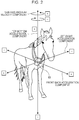
- FIG. 2 is a diagram illustrating an example of the chest sensor and an example of components of the measured data.
- the chest sensor 10 is attached to the chest of the horse.
- Data measured by the chest sensor 10 includes a top-bottom acceleration component, a left-right acceleration component, and a front-back acceleration component in the three axes, the top-bottom direction of the horse, the left-right direction of the horse, and the front-back direction of the horse.
- the measured data includes a yaw-axis angular velocity component in a rotational direction about an axis extending in the top-bottom direction.
- an upward direction with respect to the horse is defined as positive in the top-bottom direction, and a downward direction with respect to the horse is defined as negative in the top-bottom direction.
- a rightward direction with respect to a movement direction of the horse is defined as positive in the left-right direction, and a leftward direction with respect to the movement direction of the horse is defined as negative in the left-right direction.
- the movement direction of the horse is defined as positive in the front-back direction, and a direction (backward direction) opposite to the movement direction of the horse is defined as negative in the front-back direction.
- a clockwise direction when viewed from the bottom of the horse toward the top of the horse in the top-bottom direction is defined as positive in the yaw axis direction
- a counterclockwise direction when viewed from the bottom of the horse toward the top of the horse in the top-bottom direction is defined as negative in the yaw axis direction.
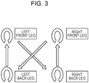
- FIG. 3 is a diagram illustrating an example of the order in which the horse puts the four legs on the ground during walking.
- the horse puts the right front leg, the left back leg, the left front leg, and the right back leg on the ground in this order during one stride when walking, for example.
- the horse walks, the horse repeatedly puts the legs on the ground in the aforementioned order.
- the horse trots, canters, or gallops, the order in which the horse puts the legs on the ground is different from the aforementioned order.
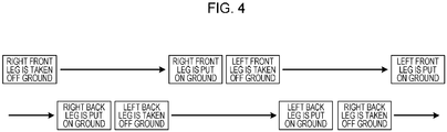
- FIG. 4 is a diagram illustrating an example of the order in which the horse puts and takes the four legs on and off the ground during walking.
- the horse takes the right front leg off the ground in a state in which the horse takes the right back leg off the ground, and the horse puts the right back leg on the ground after taking the right front leg off the ground.
- the horse takes the left back leg off the ground, puts the right front leg on the ground, takes the left front leg off the ground, and puts the left back leg on the ground.
- the horse takes the right back leg off the ground and puts the left front leg on the ground.
- the horse repeatedly puts and takes the four legs on and off the ground in this order.
- FIG. 5 is a diagram illustrating an example of data measured during walking.
- a graph 20 illustrated in FIG. 5 is obtained by plotting a left-right acceleration component, a top-bottom acceleration component, and a front-back acceleration component that are included in the measured data. As indicated in the graph 20, it is apparent that the acceleration components periodically repeatedly change.
- the acceleration components are data measured at time intervals of 40 milliseconds. Plotted values, amplitude, periods, waveforms, and the like of the measured data may vary depending on the horse.
- the injury detecting device 100 includes a communication section 110, a display section 111, an operating section 112, a storage section 120, and a controller 130.
- the injury detecting device 100 may include not only the functional sections illustrated in FIG. 1 but also various functional functions that are included in an existing computer and are an input device, an output device, and the like, for example.
- the communication section 110 is achieved by a communication module or the like such as a wireless LAN, for example.
- the communication section 110 is, for example, a communication interface that is wirelessly connected to the chest sensor 10 via the wireless LAN and communicates information with the chest sensor 10.
- the communication section 110 receives the measured data from the chest sensor 10.
- the communication section 110 outputs the received measured data to the controller 130.
- the display section 111 is a display device that displays various types of information.
- the display section 111 is achieved by a liquid crystal display or the like as a display device, for example.
- the display section 111 displays various screens including a display screen received from the controller 130.
- the operating section 112 is an input device that receives various operations from a user of the injury detecting device 100.
- the operating section 112 is achieved by a keyboard, a mouse, or the like as an input device, for example.
- the operating section 112 outputs, as operational information, an operation input by the user to the controller 130.
- the storage section 120 is achieved by a storage device such as a semiconductor memory element that is a RAM, a flash memory, or the like, a hard disk, an optical disc, or the like, for example.
- the storage section 120 includes a measured data storage section 121 and an analyzed data storage section 122.
- the storage section 120 stores information to be used for a process to be executed by the controller 130.
- the measured data storage section 121 stores the measured data.
- the measured data storage section 121 associates values of the top-bottom acceleration, the left-right acceleration, the front-back acceleration, and the yaw-axis angular velocity with data numbers and stores the values associated with the data numbers.
- Each of the data numbers is a uniquely assigned number and is an identifier identifying measured data.
- the three types of acceleration and the angular velocity are measured at the time intervals of 40 milliseconds, for example. Top-bottom acceleration, left-right acceleration, front-back acceleration, and an angular velocity that are measured at the same time are associated with the same data number.
- the analyzed data storage section 122 stores analyzed data obtained by classifying the timing of putting the legs on the ground into multiple groups based on values, corresponding to the timing of putting the legs on the ground, of the front-back acceleration.
- FIG. 6 is a diagram illustrating an example of the analyzed data storage section. As illustrated in FIG. 6 , in the analyzed data storage section 122, an abscissa indicates three groups A, B, and C for the left legs and three groups A, B, and C for the right legs. In the analyzed data storage section 122, an ordinate indicates the four legs. In the example illustrated in FIG.
- the group A for the right legs indicates “0”
- the group B for the right legs indicates "3056”
- the group C for the right legs indicates "18”.
- the groups A, B, and C for the left legs indicate "0" in the first row.
- FIG. 7 is a diagram illustrating another example of the analyzed data storage section.
- An analyzed data storage section 122a illustrated in FIG. 7 indicates percentages of data included in the analyzed data storage section 122 illustrated in FIG. 6 .
- the analyzed data storage section 122 may use percentages to indicate the numbers of times that the horse puts each of the legs on the ground.
- the numbers of times that the horse puts the legs on the ground may be indicated by the numbers of time intervals at which when the horse puts the legs on the ground, for example. Details are described later with reference to FIG. 11 .
- the controller 130 is achieved by causing a CPU, an MPU, or the like to use a RAM as a work region to execute a program stored in an internal storage device, for example.
- the controller 130 may be achieved by an integrated circuit such as an ASIC or an FPGA, for example.
- the controller 130 includes a receiver 131, a first determiner 132, and a second determiner 133.
- the controller 130 executes information processing functions described later or achieves information processing effects described later.
- An internal configuration of the controller 130 is not limited to the configuration illustrated in FIG. 1 .
- the controller 130 may have another configuration as long as information processing described later is executed in the configuration.
- the receiver 131 receives the measured data from the chest sensor 10 via the communication section 110.
- the receiver 131 causes the received measured data to be stored in the measured data storage section 121.
- a reading device not illustrated may read the measured data from a portable recording medium storing the measured data, and the receiver 131 may receive the measured data from the reading device.
- the receiver 131 outputs, to the first determiner 132, an instruction to determine the timing of putting the legs on the ground.
- the receiver 131 receives the measured data that is based on the gait of the quadruped and includes the acceleration in the top-bottom direction and the acceleration in the front-back direction.
- the receiver 131 receives the data measured during walking.
- the receiver 131 receives the measured data including the angular velocity about the yaw axis.
- the first determiner 132 Upon receiving the instruction to determine the timing of putting the legs on the ground from the receiver 131, the first determiner 132 references the measured data storage section 121 and determines, based on the measured data, the timing of putting the legs on the ground and the left or right of each of the legs. First, the first determiner 132 determines, based on the top-bottom acceleration, the timing of putting the front legs on the ground. For example, the first determiner 132 determines that the time when the top-bottom acceleration is reversed from negative to positive and from positive to negative is the time when the horse puts the front legs on the ground.
- the first determiner 132 determines that the horse puts one of the back legs on the ground at midpoints in time between the time when the horse puts one of the front legs on the ground and the time when the horse puts the other one of the front legs on the ground, and that the horse puts the other one of the back legs on the ground at midpoints in time between the time when the horse puts the other one of the front legs on the ground and the time when the horse puts the one of the front legs on the ground.
- the first determiner 132 determines, based on the yaw-axis angular velocity, the timing of taking the front legs off the ground and the left or right of each of the legs. For example, the first determiner 132 determines that the time when the sign of the yaw-axis angular velocity is reversed to positive is the time when the horse takes the right front leg off the ground. In addition, for example, the first determiner 132 determines that the time when the sign of the yaw-axis angular velocity is reversed to negative is the time when the horse takes the left front leg off the ground.
- the sign of the yaw-axis angular velocity varies depending on which rotational direction about the axis extending in the top-bottom direction is treated as positive, as illustrated in FIG. 2 .
- the first determiner 132 determines that the horse takes the left back leg off the ground at midpoints in time between the time when the horse takes the right front leg off the ground and the time when the horse takes the left front leg off the ground. In addition, the first determiner 132 determines that the horse takes the right back leg off the ground at midpoints in time between the time when the horse takes the left front leg off the ground and the time when the horse takes the right front leg off the ground.
- the first determiner 132 determines, based on the timing of taking the legs off the ground, the left or right of each of the legs for the timing of putting the front legs on the ground and the timing of putting the back legs on the ground. Specifically, the first determiner 132 determines the timing of putting each of the four legs on the ground. The first determiner 132 outputs information of the determined timing of putting each of the four legs on the ground to the second determiner 133.
- the first determiner 132 determines the timing of putting the legs on the ground based on the top-bottom acceleration included in the received measured data. In addition, the first determiner 132 determines the left or right of each of the legs based on the angular velocity about the yaw axis, determines the front or back of each of the legs based on the acceleration in the top-bottom direction, and determines the timing of putting the left and right back legs based on the timing of putting the left and right front legs on the ground.
- FIG. 8 is a diagram illustrating an example of the timing of taking and putting the legs off and on the ground during walking.
- a graph 21 illustrated in FIG. 8 indicates the timing of taking and putting legs of a certain horse off and on the ground for data obtained by measuring the certain horse during the time when the certain horse walks.
- the time when the sign of an acceleration component in a top-bottom direction of the horse is reversed from negative to positive is the time when the horse puts a front leg on the ground and that the horse puts one of the back legs on the ground at midpoints in time between the time when the horse puts one of the front legs on the ground and the time when the horse puts the other one of the front legs on the ground and the horse puts the other one of the back legs on the ground at midpoints in time between the time when the horse puts the other one of the front legs on the ground and the time when the horse puts the one of the front legs on the ground.
- the timing of taking the left and right front legs off the ground is determined based on the time when the sign of an angular velocity component about a yaw axis is reversed from negative to positive and from positive to negative, and it is determined that the horse takes one of the back legs off the ground at midpoints in time between the time when the horse takes one of the front legs off the ground and the time when the horse takes the other one of the front legs off the ground and the horse takes the other one of the back legs off the ground at midpoints in time between the time when the horse takes the other one of the front legs off the ground and the time when the horse takes the one of the front legs off the ground.
- the left or right of each of the front and back legs put on the ground is determined based on the timing of taking the legs off the ground.
- FIG. 9 is a diagram illustrating an example in which the timing of taking and putting the legs off and on the ground is added to the data measured during walking.
- FIG. 9 illustrates the case where timing 22, determined by the first determiner 132, of taking and putting the legs off and on the ground is added to the graph 20 of the measured data illustrated in FIG. 5 .
- the left or right of each of the legs is determined based on the graph using the left-right acceleration component, instead of the yaw-axis angular velocity component.
- the left-right acceleration component is positive values before and after the putting of the right back leg on the ground.
- the left-right acceleration component is negative values before and after the putting of the left back leg on the ground.
- the left-right acceleration component may be shifted from the timing of putting the legs on the ground, depending on the horse. Based on the measured data of the graph 20 illustrated in FIG. 9 , it is determined that the horse puts the left front leg on the ground when the top-bottom acceleration component is reversed from negative to positive.
- the horse puts the right front leg on the ground when the top-bottom acceleration component is reversed from positive to negative this is considered to depend on the horse. In this case, for example, it may be determined that the horse puts the right front leg on the ground at midpoints in time between the time when the horse puts the left front leg on the ground and the time when the horse puts the left front leg on the ground next.
- the second determiner 133 Upon receiving the information of the timing of putting the legs on the ground from the first determiner 132, the second determiner 133 references the measured data storage section 121 and calculates values that are based on the front-back acceleration and correspond to the timing of putting the legs on the ground. For example, the second determiner 133 may use, as the values based on the front-back acceleration, the areas of predetermined ranges of a graph of the front-back acceleration within time intervals between time points when the horse puts legs on the ground or the numbers of plotted values in predetermined ranges of the graph of the front-back acceleration within the time intervals between the time points when the horse puts the legs on the ground.
- the areas of the predetermined ranges of the graph of the front-back acceleration may include the areas of ranges of the graph during a certain time interval that is included in a time period from the putting of a certain front leg on the ground to the putting of a back leg on the ground immediately after the putting of the certain front leg on the ground and is from the time when the front-back acceleration becomes highest to the time when the front-back acceleration becomes lowest, for example.
- the areas of the predetermined ranges of the graph of the front-back acceleration may include the areas of ranges of the graph during a certain time interval that is included in a time period from the putting of a certain back leg on the ground to the putting of a front leg on the ground immediately after the putting of the certain back leg on the ground and is from the time when the front-back acceleration becomes lowest to the time when the front-back acceleration becomes highest, for example.
- the numbers of the plotted values in the predetermined ranges of the graph of the front-back acceleration may include the number of plotted values during a time interval that is included in a time period from the putting of a certain front leg on the ground to the putting of a back leg on the ground immediately after the putting of the certain front leg on the ground and is from the time when the horse puts the certain front leg on the ground to the time when the front-back acceleration becomes highest, and the number of plotted values during a time interval that is included in the time period and is from the time when the front-back acceleration is reversed from positive to negative to the time when the front-back acceleration becomes lowest, for example.
- the numbers of the plotted values in the predetermined ranges of the graph of the front-back acceleration may include the number of plotted values during a time interval that is included in a time period from the putting of a certain back leg on the ground to the putting of a front leg immediately after the putting of the certain back leg on the ground and is from the time when the horse puts the certain back leg on the ground to the time when the front-back acceleration becomes lowest, and the number of plotted values during a time interval that is included in the time period and is from the time when the front-back acceleration is reversed from negative to positive to the time when the front-back acceleration becomes highest.
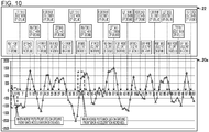
- FIG. 10 is a diagram illustrating an example of relationships between the timing of taking and putting the legs off and on the ground during walking and the front-back acceleration.
- a graph 20a illustrated in FIG. 10 is obtained by extracting a graph of the front-back acceleration from the graph 20 illustrated in FIG. 9 .
- the scale of the ordinate (indicating the acceleration) of the graph is enlarged 2 times.
- the timing 22 of taking and putting the legs off and on the ground is the same as or similar to that illustrated in FIG. 9 .
- the front-back acceleration decreases or acceleration (hereinafter also referred to as backward acceleration) in a backward direction of the horse occurs.
- the front-back acceleration increases or acceleration (hereinafter referred to as frontward acceleration) in a frontward direction of the horse occurs.
- frontward acceleration increases or acceleration in a frontward direction of the horse occurs.
- the inclination of the graph of the front-back acceleration that increases or decreases when the horse puts a leg on the ground becomes larger than that in a normal state or the difference between the highest value of the front-back acceleration and the lowest value of the front-back acceleration becomes larger than that in the normal state.
- the difference between a graph of the front-back acceleration obtained in the normal state and a graph of the front-back acceleration obtained during lameness varies depending on the horse or physical conditions of the horse.
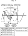
- FIG. 11 is a diagram illustrating an example of the front-back acceleration corresponding to the timing of putting the legs on the ground.
- the area of a predetermined range of a graph of the front-back acceleration corresponding to the timing of putting a front leg on the ground is calculated based on regions 31a and 31b of the graph of the front-back acceleration during a time interval from the time when the horse puts a certain front leg on the ground to the time when the horse puts a back leg on the ground immediately after putting the certain front leg on the ground.
- FIG. 11 for example, the area of a predetermined range of a graph of the front-back acceleration corresponding to the timing of putting a front leg on the ground is calculated based on regions 31a and 31b of the graph of the front-back acceleration during a time interval from the time when the horse puts a certain front leg on the ground to the time when the horse puts a back leg on the ground immediately after putting the certain front leg on the ground.
- the area of a predetermined range of the graph of the front-back acceleration corresponding to the timing of putting a back leg on the ground is calculated based on regions 32a and 32b of the graph of the front-back acceleration during a time interval from the time when the horse puts the back leg on the ground to the time when the horse puts a front leg on the ground immediately after putting the back leg on the ground, for example.
- the area of the predetermined range of the graph of the front-back acceleration corresponding to the timing of putting the back leg on the ground is calculated by subtracting the area of the region 32b from the area of the region 32a, for example.
- the graph of the front-back acceleration assumes that the acceleration during the time interval from the time when the horse puts the front leg on the ground to the time when the horse puts the back leg on the ground immediately after putting the front leg on the ground is affected by the front leg and that the acceleration during the time interval from the time when the horse puts the back leg on the ground to the time when the horse puts the front leg on the ground immediately after putting the back leg on the ground is affected by the back leg.
- the number of plotted values in a range 33 that is included in the time interval from the putting of the front leg on the ground to the putting of the back leg on the ground immediately after the putting of the front leg on the ground and is from the time when the horse puts the front leg on the ground to the time when the front-back acceleration becomes highest and the number of plotted values in a range 34 that is included in the time interval from the putting of the front leg on the ground to the putting of the back leg on the ground immediately after the putting of the front leg on the ground and is from the time when the front-back acceleration is reversed from positive to negative to the time when the front-back acceleration becomes lowest may be used.
- the number of plotted values in a range 33 that is included in the time interval from the putting of the front leg on the ground to the putting of the back leg on the ground immediately after the putting of the front leg on the ground and is from the time when the front-back acceleration is reversed from positive to negative to the time when the front-back acceleration becomes lowest may be used.
- the number of plotted values in a predetermined range of the graph of the front-back acceleration corresponding to the timing of putting the front leg on the ground is calculated by subtracting the number of plotted values in the range 34 from the number of plotted values in the range 33. If the number of plotted values is used, as the number of plotted values is smaller, the horse has moved more abruptly. If the number of plotted values is a negative value, the number of plotted values may be corrected by adding a correction value to the number of plotted values in the range 33, for example.
- the second determiner 133 calculates values that are based on the front-back acceleration and correspond to the timing of putting the legs on the ground, or calculates the areas of predetermined ranges of the graph of the front-back acceleration within time intervals between time points when the horse puts legs on the ground, or calculates the numbers of plotted values of the graph of the front-back acceleration within the time intervals, and classifies the values into groups A, B, and C for each of the legs, for example.
- the second determiner 133 uses the ABC analysis or the like to classify the values into the groups, for example.
- the number of groups into which the values are classified is not limited to 3 and may be an arbitrary number of 2 or more. In this case, values including the maximum value and close to the maximum value correspond to the group A, and values including the minimum value and close to the minimum value correspond to the group C.
- the second determiner 133 calculates a threshold for the groups A and B and a threshold for the groups B and C to classify the values into the three groups A, B, and C.
- the second determiner 133 calculates an average, a variance, and a standard deviation based on the areas of predetermined ranges of the graph of the front-back acceleration within time periods (time intervals) between time points when the horse puts the legs on the ground.
- the second determiner 133 multiplies the standard deviation by ⁇ 3 or increases a range to a range of ⁇ 3 ⁇ and treats the standard deviation multiplied by 3 as the threshold for the groups A and B and treats the standard deviation multiplied by -3 as the threshold for the groups B and C. If the number of plotted values is used, the second determiner 133 calculates the average, the variance, and the standard deviation based on the numbers of plotted values in predetermined ranges of the graph of the front-back acceleration within time periods (time intervals) between time points when the horse puts the legs on the ground.
- the second determiner 133 uses the calculated threshold for the groups A and B and the calculated threshold for the groups B and C to classify, for all time intervals of the measured data, areas associated with the timing of putting the legs on the ground or the numbers of plotted values associated with the timing of putting the legs on the ground into the groups A, B, and C.
- a threshold for the groups A and B and a threshold for the groups B and C may be calculated for each horse based on past measured data.
- the second determiner 133 causes the areas classified into the groups or the numbers, classified into the groups, of plotted values, or the numbers of times that the horse puts each leg on the ground or the ratios of the numbers of times that the horse puts each leg on the ground to be stored as analyzed data in the analyzed data storage section 122.
- the second determiner 133 After classifying the areas associated with the timing of putting the legs on the ground or the numbers of plotted values into the groups, the second determiner 133 extracts a group satisfying a first requirement or groups satisfying a second requirement for each leg based on numbers belonging to the groups A and C.
- the first requirement is that a number (or a number classified into a group) belonging to a group is equal to or larger than a predetermined value (of, for example, "16 to 18").
- the second requirement is that a number (or a number classified into a group) belonging to any of the groups A and C is equal to or smaller than a first value (of, for example, "0 to 2") and that a number (or a number classified into a group) belonging to the other of the groups A and C is equal to or larger than a second value (of, for example, "10").
- the first and second requirements may be defined using ratios (percentages). For example, the predetermined value used for the first requirement may be "1.00 %", the first value used for the second requirement may be "0.06 %", and the second value used for the second requirement may be "0.33 %".
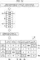
- FIG. 12 is a diagram illustrating an example of the classification of areas associated with the timing of putting the legs on the ground.
- the second determiner 133 uses the threshold (+3a) for the groups A and B and the threshold (-3 ⁇ ) for the groups B and C to classify each of the areas associated with the timing of putting the legs on the ground into any of the three groups A, B, and C.
- the example illustrated in FIG. 12 assumes that the threshold for the groups A and B is "50" and that the threshold for the groups B and C is "15". If a certain area is larger than "50", the second determiner 133 classifies the certain area into the group A.
- the second determiner 133 classifies the certain area into the group C. In addition, if the certain area is equal to or larger than "15" and equal to or smaller than "60", the second determiner 133 classifies the certain area into the group B.
- the second determiner 133 calculates, for each of the legs, the number, belonging to each group, of times that the horse has put the leg on the ground.
- the group A for the right legs indicates "0”
- the group B for the right legs indicates "3056”
- the group C for the right legs indicates "18”
- the groups A, B, and C for the left legs indicate "0”.
- the group A for the left legs indicates "9”
- the group B for the left legs indicates "3310”
- the group C for the left legs indicates "15”
- the groups A, B, and C for the right legs indicate "0".
- the group A for the left legs indicates “1"
- the group B for the left legs indicates “3105"
- the group C for the left legs indicates “41”
- the groups A, B, and C for the right legs indicate “0”.
- the group A for the right legs indicates "16”
- the group B for the right legs indicates "3082”
- the group C for the right legs indicates "0”
- the groups A, B, and C for the left legs indicate "0”.
- the second determiner 133 causes the results of the classification to be stored as analyzed data in the analyzed data storage section 122.
- the second determiner 133 extracts, as a group satisfying the first requirement, a group 36 that is indicated in the row indicating the left back leg and is indicated in a column indicating the group C for the left legs.
- the second determiner 133 extracts, as groups satisfying the second requirement, groups 37a and 37c indicated in the row indicating the right front leg, groups 38a and 38c indicated in the row indicating the left back leg, and groups 39a and 39c indicated in the row indicating the right back leg.
- the second determiner 133 determines whether or not the second determiner 133 has extracted a group satisfying the first requirement or groups satisfying the second requirement. If the second determiner 133 determines that the second determiner 133 has not extracted the group satisfying the first requirement or the groups satisfying the second requirement, the second determiner 133 determines that a lame leg has not been detected, and the second determiner 133 causes the display section 111 to display a determination result indicating that a lame leg has not been detected.
- the second determiner 133 determines that the second determiner 133 has extracted the group satisfying the first requirement or the groups satisfying the second requirement, the second determiner 133 determines a lame leg based on a lame leg determination table and the extracted group or groups for each leg. The second determiner 133 causes the display section 111 to display the result of determining the lame leg.
- FIG. 13 is a diagram illustrating an example of the lame leg determination table.
- a lame leg determination table 40 illustrated in FIG. 13 includes a table 41 and a table 42.
- the table 41 indicates whether or not legs other than a lame leg are affected by the lameness upon the putting of the lame leg on the ground.
- each lame leg is associated with information indicating whether or not legs other than the lame leg are affected by the lameness upon the putting of the lame leg on the ground.
- the table 42 indicates changes in behaviors of each lame leg and the other legs.
- the lame leg determination table 40 is an example of a determination table indicating relationships between lame legs and increasing or decreasing trends in acceleration in the front-back direction.
- a first column of the lame leg determination table 40 indicates that if the right front leg is lame, the right back leg is not affected by the lameness upon the putting of the lame right front leg on the ground, and the left front leg and the left back leg are affected by the lameness upon the putting of the lame right front leg on the ground.
- the first column of the lame leg determination table 40 indicates that backward acceleration that normally occurs is reduced upon the putting of the lame right front leg on the ground. When the horse puts the right back leg on the ground, normal forward acceleration occurs. When the horse puts the left front leg on the ground, the left front leg is slightly affected by the lameness, and normal backward acceleration occurs.
- second to fourth columns of the lame leg determination table 40 indicate relationships between each lame leg and the other legs whose behaviors change upon the putting of the lame leg on the ground.
- the extracted groups 36, 37a, 37c, 38a, 38c, 39a, and 39c illustrated in FIG. 12 are applied to the lame leg determination table 40 illustrated in FIG. 13 .
- the group 36 satisfying the first requirement belongs to the group C and indicates the putting of the left back leg on the ground, areas associated with the timing of putting the left back leg on the ground are small or the front-back acceleration is reduced compared with the normal state, the second determiner 133 determines that the right front leg or the left back leg is lame.
- the groups 37a and 37c satisfying the second requirement belong to the groups A and C, respectively and indicate the putting of the right front leg on the ground.
- the groups 37a and 37c indicate that there is no case where an area associated with the timing of putting the right front leg on the ground is larger than the threshold for the groups A and B and the number of times that an area associated with the timing of putting the right front leg on the ground is smaller than the threshold for the groups B and C is in the normal range.
- the second determiner 133 determines, based on the groups 37a and 37c, that the right front leg is lame.
- the groups 38a and 38c belong to the groups A and C, respectively and indicate the putting of the left back leg on the ground.
- the groups 38a and 38c indicate that the number of times that an area associated with the timing of putting the left back leg on the ground is larger than the threshold for the groups A and B is small, and that the number of times that an area associated with the timing of putting the left back leg on the ground is smaller than the threshold for the groups B and C is large.
- the second determiner 133 determines, based on the groups 38a and 38c, that the right front leg or the left back leg is lame.
- the group 38c is the same group as the group 36. However, since whether or not a combination of the groups 38a and 38c satisfies the second requirement is determined, the different reference symbols are used.
- the groups 39a and 39c belong to the groups A and C, respectively and indicate the putting of the right back leg on the ground.
- the groups 39a and 39c indicate that the number of times that an area associated with the timing of putting the right back leg on the ground is larger than the threshold for the groups A and B is in the normal range and there is no case where an area associated with the timing of putting the right back leg on the ground is smaller than the threshold for the groups B and C.
- the second determiner 133 determines, based on the groups 39a and 39c, that the right back leg and the left front leg are not lame.
- the second determiner 133 determines that the right front leg is lame, since the number of times that the right front leg is determined to be lame is the largest among the results of making the determination based on the groups 36, 37a, 37c, 38a, 38c, 39a, and 39c.
- the second determiner 133 may determine that the right back leg is lame based on the occurrence of the forward acceleration upon the putting of the right front leg on the ground, and the second determiner 133 may determine that the left back leg is lame based on the occurrence of the forward acceleration upon the putting of the left front leg on the ground.
- the second determiner 133 may determine that the right front leg is lame. Furthermore, if one or multiple requirements indicated in cells included in the third column of the lame leg determination table 40 and included in a row indicating the putting of the right back leg on the ground and the row indicating the putting of the left front leg on the ground are satisfied, the second determiner 133 may determine that the left front leg is lame.
- the second determiner 133 determines whether or not the legs are injured based on values, corresponding to the determined timing of putting the legs on the ground, of the acceleration in the front-back direction. In addition, the second determiner 133 determines whether or not each of the legs is injured based on values, corresponding to the determined timing of putting each of the legs on the ground, of the acceleration in the front-back direction.
- the second determiner 133 classifies, into the multiple groups for each of the legs, the areas of ranges of a graph of the front-back acceleration within time intervals between multiple time points when the horse puts the target leg on the ground and when the horse puts another leg on the ground immediately after putting the target leg on the ground, and the second determiner 133 determines whether or not each of the legs is injured based on the numbers, classified into the group of values including the maximum value and close to the maximum value and the group of values including the minimum value and close to the minimum value, of times that the horse puts the legs on the ground.
- the second determiner 133 classifies, into the multiple groups for each of the legs, the numbers of plotted values of the graph of the acceleration in the front-back direction within time intervals between multiple time points when the horse puts the target leg on the ground and when the horse puts another leg on the ground immediately after putting the target leg on the ground, and the second determiner 133 determines whether or not each of the legs is injured based on the numbers, classified into the group of values including the maximum value and the group of values including the minimum value, of times that the horse puts the legs on the ground.
- the second determiner 133 uses the determination table indicating relationships between lame legs and increasing or decreasing trends in acceleration in the front-back direction to determine a lame leg based on the increasing or decreasing trends, indicated by the numbers of times that the horse puts the legs on the ground, in the acceleration in the front-back direction.
- FIG. 14 is a diagram illustrating an example of the comparison of the waveforms of the front-back acceleration.
- a graph 50 that indicates an uninjured horse indicates a waveform of the front-back acceleration that repeatedly changes in a regular manner
- a graph 51 that indicates an injured horse indicates a waveform of the front-back acceleration that changes in an irregular manner. If the horse is injured, the waveform of the front-back acceleration is disturbed as described above.
- FIG. 14 is a diagram illustrating an example of the comparison of the waveforms of the front-back acceleration.
- the difference between a range of values of the front-back acceleration of the horse indicated by the graph 50 and a range of values of the front-back acceleration of the horse indicated by the graph 51 is caused by the difference between the horses.
- FIG. 15 is a flowchart illustrating an example of an injury detection process according to the embodiment.
- the receiver 131 receives the measured data from the chest sensor 10 (in step S1).
- the receiver 131 causes the received measured data to be stored in the measured data storage section 121.
- the receiver 131 outputs, to the first determiner 131, an instruction to determine the timing of putting the legs on the ground.
- the first determiner 131 Upon receiving the instruction to determine the timing of putting the legs on the ground from the receiver 131, the first determiner 131 references the measured data storage section 121 and determines, based on the measured data, the timing of putting each of the legs on the ground and the left or right of each of the legs (in step S2). The first determiner 132 outputs information of the timing of putting each of the legs on the ground to the second determiner 133.
- the second determiner 133 Upon receiving the information of the timing of putting each of the legs on the ground from the first determiner 132, the second determiner 133 references the measured data storage section 121 and calculates values that are based on the front-back acceleration and correspond to the timing of putting the legs on the ground.
- the second determiner 133 classifies, into the groups A, B, and C for each of the legs, the values that are based on the front-back acceleration and correspond to the timing of putting the legs on the ground (in step S3).
- the second determiner 133 After classifying, into the groups, the values that are based on the front-back acceleration and correspond to the timing of putting the legs on the ground, the second determiner 133 extracts, for each of the legs, a group satisfying the first requirement or groups satisfying the second requirement based on numbers belonging to the groups A and C (in step S4). The second determiner 133 determines whether or not the second determiner 133 has extracted the group satisfying the first requirement or the groups satisfying the second requirement (in step S5).
- the second determiner 133 determines that the second determiner 133 has not extracted the group satisfying the first requirement or the groups satisfying the second requirement (No in step S5), the second determiner 133 determines that a lame leg has not been detected (in step S6).
- the second determiner 133 causes the display section 111 to display a determination result indicating that a lame leg has not been detected (in step S8).
- the second determiner 133 determines that the second determiner 133 has extracted the group satisfying the first requirement or the groups satisfying the second requirement (Yes in step S5), the second determiner 133 determines a lame leg based on the group or groups extracted for each leg and the lame leg determination table (in step S7).
- the second determiner 133 causes the display section 111 to display the result of determining the lame leg (in step S8).
- the injury detecting device 100 may detect an injury without causing physical stress.
- the top-bottom acceleration, the left-right acceleration, the front-back acceleration, and the yaw-axis angular velocity are used to determine whether or not each of the legs is lame and detect whether or not each of the legs of the horse is injured.
- the embodiment is not limited to this.
- the top-bottom acceleration and the top-bottom acceleration may be used to detect whether or not a front or back leg of the horse is injured.
- whether or not each of the legs of the horse is injured is detected based on the data measured during the time when the horse walks.
- the embodiment is not limited to this.
- the injury detection system may detect whether or not each of the legs of the other quadruped is injured.
- the injury detecting device 100 receives measured data that is based on the gait of the quadruped and includes acceleration in a top-bottom direction of the quadruped and acceleration in a front-back direction of the quadruped. In addition, the injury detecting device 100 determines the timing of putting the legs of the quadruped on the ground based on the acceleration, included in the received measured data, in the top-bottom direction. In addition, the injury detecting device 100 determines whether or not each of the legs is injured based on values, corresponding to the determined timing of putting the legs on the ground, of the acceleration in the top-back direction. As a result, the injury detecting device 100 may detect an injury without causing physical stress.
- the injury detecting device 100 receives the data measured during the time when the gait of the quadruped is walk. As a result, the injury detecting device 100 may detect an injury from the data measured during walking without causing physical stress.
- the measured data received by the injury detecting device 100 further includes an angular velocity about a yaw axis.
- the injury detecting device 100 determines the left or right of each of the legs based on the angular velocity about the yaw axis, determines the front or back of each of the legs based on the acceleration in the top-bottom direction, and determines the timing of putting the left and right back legs on the ground based on the timing of putting the left and right front legs on the ground.
- the injury detecting device 100 determines whether or not each of the legs is injured based on values, corresponding to the determined timing of putting each of the legs on the ground, of the acceleration in the front-back direction. As a result, the injury detecting device 100 may determine whether or not any of the four legs is injured.
- the injury detecting device 100 classifies, into multiple groups for each of the legs, the areas of ranges of a graph of the acceleration in the front-back direction within time intervals between multiple time points when the quadruped puts the target leg on the ground and when the quadruped puts another leg on the ground immediately after putting the target leg on the ground, and the injury detecting device 100 determines whether or not each of the legs is injured based on the numbers, classified into a group of values including the maximum value and close to the maximum value and a group of values including the minimum value and close to the minimum value, of times that the quadruped puts the legs on the ground. As a result, the injury detecting device 100 may determine whether or not any of the legs is injured.
- the injury detecting device 100 classifies, into the multiple groups for each of the legs, the numbers of plotted values of the graph of the acceleration in the front-back direction within time intervals between multiple time points between the quadruped puts the legs on the ground. Furthermore, the injury detecting device 100 determines whether or not each of the legs is injured based on the numbers, classified into the group of values including the maximum value and close to the maximum value and the group of values including the minimum value and close to the minimum value, of times that the quadruped puts the legs on the ground. As a result, the injury detecting device 100 may determine whether or not any of the four legs is injured.
- the injury detecting device 100 uses a determination table indicating relationships between lame legs and increasing or decreasing trends in the acceleration in the front-back direction to determine a lame leg based on the increasing or decreasing trends, indicated by the numbers of times that the quadruped puts the legs on the ground, of the acceleration in the front-back direction. As a result, the injury detecting device 100 may determine whether or not any of the four legs is injured.
- the constituent elements of the sections illustrated in the drawings may not be physically configured as illustrated in the drawings. Specifically, the specific forms of the distribution and integration of the sections are not limited to those illustrated in the drawings, and all or a portion of the sections may be functionally or physically distributed and integrated in arbitrary units, depending on various loads, usage states, and the like.
- the receiver 131 and the first determiner 133 may be integrated with each other.
- the processes illustrated may not be executed in the aforementioned order. Two or more of the processes may be executed at the same time without the contradiction of the details of the processes, or the processes may be executed in different order without the contradiction of the details of the processes.
- all or an arbitrary portion of the various processing functions that are executed in the devices may be executed by a CPU (or a microcomputer such as an MPU or a micro controller unit (MCU)).
- a CPU or a microcomputer such as an MPU or a micro controller unit (MCU)
- all or a portion of the various processing functions may be executed by a program analyzed and executed by the CPU (or the microcomputer such as the MPU or the MCU) or by hardware with wired logic.
- FIG. 16 is a diagram illustrating an example of the computer that executes the program for detecting an injury of a quadruped.
- a computer 200 includes a CPU 201 that executes various types of arithmetic processing, an input device 202 that receives input data, and a monitor 203.
- the computer 200 also includes a medium reading device 204 that reads the program and the like from a storage medium, an interface device 205 that is connected to various devices, and a communication device 206 that is connected to another information processing device or the like wirelessly or via a cable.
- the computer 200 also includes a RAM 207 that temporarily stores various types of information, and a hard disk device 208.
- the devices 201 to 208 are connected to a bus 209.
- the program for detecting an injury of a quadruped is stored.
- the program for detecting an injury of a quadruped has the same functions as the processing sections that are the receiver 131, the first determiner 132, and the second determiner 133, which are illustrated in FIG. 1 .
- various types of data that achieve the measured data storage section 121, the analyzed data storage section 122, and the program for detecting an injury of a quadruped are stored.
- the input device 202 receives various types of input information such as operational information from a user of the computer 200, for example.
- the monitor 203 displays various screens including an output screen to the user of the computer 200, for example.
- the medium reading device 204 reads the measured data from the storage medium.
- the interface device 205 is connected to a printing device or the like, for example.
- the communication device 206 is connected to the chest sensor 10 and communicates various types of information such as the measured data with the chest sensor 10.
- the CPU 201 reads the program, stored in the hard disk device 208, for detecting an injury of a quadruped, loads the read program into the RAM 207, and executes the program, thereby executing the various processes.
- the program may cause the computer 200 to function as the receiver 131, the first determiner 132, and the second determiner 133, which are illustrated in FIG. 1 .
- the aforementioned program for detecting an injury of a quadruped may not be stored in the hard disk device 208.
- the computer 200 may read the program stored in a storage medium readable by the computer 200 and execute the read program.
- the storage medium readable by the computer 200 corresponds to a CD-ROM, a DVD, a portable recording medium such as a USB memory, a semiconductor memory such as a flash memory, a hard disk drive, or the like, for example.
- the program for detecting an injury of a quadruped may be stored in a device connected to a public line, the Internet, a LAN, or the like, and the computer 200 may read the program for detecting an injury of a quadruped from the public line, the Internet, the LAN, or the like and execute the read program for detecting an injury of a quadruped.
Landscapes
- Life Sciences & Earth Sciences (AREA)
- Health & Medical Sciences (AREA)
- Engineering & Computer Science (AREA)
- Environmental Sciences (AREA)
- Physics & Mathematics (AREA)
- General Health & Medical Sciences (AREA)
- Animal Behavior & Ethology (AREA)
- Biophysics (AREA)
- Medical Informatics (AREA)
- Public Health (AREA)
- Artificial Intelligence (AREA)
- Physiology (AREA)
- Pathology (AREA)
- Biomedical Technology (AREA)
- Heart & Thoracic Surgery (AREA)
- Molecular Biology (AREA)
- Surgery (AREA)
- Veterinary Medicine (AREA)
- Biodiversity & Conservation Biology (AREA)
- Animal Husbandry (AREA)
- Fuzzy Systems (AREA)
- Evolutionary Computation (AREA)
- Psychiatry (AREA)
- Dentistry (AREA)
- Oral & Maxillofacial Surgery (AREA)
- Mathematical Physics (AREA)
- Computer Vision & Pattern Recognition (AREA)
- Signal Processing (AREA)
- Physical Education & Sports Medicine (AREA)
- Zoology (AREA)
- Measurement Of The Respiration, Hearing Ability, Form, And Blood Characteristics Of Living Organisms (AREA)
- Management, Administration, Business Operations System, And Electronic Commerce (AREA)
Abstract
Description
- The embodiments discussed herein are related to a device for detecting an injury of a quadruped, a method for detecting an injury of a quadruped, and a program for detecting an injury of a quadruped.
- For example, racehorses are trained by horse trainers who are managers to cause stress on minds and bodies of the horses in order to improve abilities of the horses. However, since horses including racehorses are living organisms, physical conditions of the horses may change day by day, and the horses may in bad conditions. One of physically bad conditions of horses is lameness that is an abnormal gait. Lameness may occur before an injury becomes major in many cases, and it is important to find lameness early in order to protect a horse. Traditionally, lameness has been found by horse managers based on their experience and instinct, but it may be hard to distinguish minor lameness and a normal state, and minor lameness may be overlooked. To avoid this, the idea of attaching various sensors to horse legs and the like and detecting lameness has been proposed. In fact, however, it is hard to attach the sensors to legs of a sensitive racehorse. In addition, the idea of attaching various sensors to a horse body and the like and detecting lameness from data measured during trotting has been proposed.
- Examples of related art are Japanese National Publication of International Patent Application No.
2008-500046 2016-096758 - However, when a person makes a horse trot to detect lameness, the trot causes larger stress on the horse than that caused by walking. Thus, lameness may become worse due to physical stress on the horse in some cases.
- According to an aspect, an object is to provide a device for detecting an injury of a quadruped, a method for detecting an injury of a quadruped, and a program for detecting an injury of a quadruped, which may detect an injury without causing physical stress.
- According to an aspect of the invention, a method for detecting an injury of a quadruped includes: receiving measured data that is based on a gait of the quadruped and includes acceleration in a top-bottom direction and acceleration in a front-back direction; determining timings of putting legs of the quadruped on the ground based on the acceleration in the top-bottom direction, included in the received measured data, and determining whether or not each of the legs is injured based on values, corresponding to the determined timing of putting the legs on the ground, of the acceleration in the front-back direction.
- An injury of a quadruped can be detected without any physical load on the quadruped.
-
-
FIG. 1 is a block diagram illustrating an example of the configuration of an injury detection system according to an embodiment; -
FIG. 2 is a diagram illustrating an example of a chest sensor and an example of components of measured data; -
FIG. 3 is a diagram illustrating an example of the order in which a horse puts four legs on the ground during walking; -
FIG. 4 is a diagram illustrating an example of the order in which the horse puts and takes the four legs on and off the ground during walking; -
FIG. 5 is a diagram illustrating an example of data measured during walking; -
FIG. 6 is a diagram illustrating an example of an analyzed data storage section; -
FIG. 7 is a diagram illustrating another example of the analyzed data storage section; -
FIG. 8 is a diagram illustrating an example of the timing of taking and putting the legs off and on the ground during walking; -
FIG. 9 is a diagram illustrating an example in which the timing of taking and putting the legs off and on the ground is added to the data measured during walking; -
FIG. 10 is a diagram illustrating an example of relationships between the timing of taking and putting the legs off and on the ground and front-back acceleration; -
FIG. 11 is a diagram illustrating an example of the front-back acceleration corresponding to the timing of putting the legs on the ground; -
FIG. 12 is a diagram illustrating an example of the classification of areas associated with the timing of putting the legs on the ground; -
FIG. 13 is a diagram illustrating an example of a lame leg determination table; -
FIG. 14 is a diagram illustrating an example of the comparison of waveforms of the front-back acceleration; -
FIG. 15 is a flowchart illustrating an example of an injury detection process according to the embodiment; and -
FIG. 16 is a diagram illustrating an example of a computer that executes a program for detecting an injury of a quadruped. - Hereinafter, embodiments of a device disclosed herein for detecting an injury of a quadruped, a method disclosed herein for detecting an injury of a quadruped, and a program disclosed herein for detecting an injury of a quadruped are described below in detail based on the accompanying drawings. Techniques disclosed herein are not limited to the embodiments. In addition, the embodiments may be combined without contradiction.
-
FIG. 1 is a block diagram illustrating an example of the configuration of an injury detection system according to an embodiment. Aninjury detection system 1 illustrated inFIG. 1 includes achest sensor 10 and aninjury detecting device 100. AlthoughFIG. 1 illustrates the case where theinjury detection system 1 includes thesingle chest sensor 10 and the singleinjury detecting device 100, the number ofchest sensors 10 and the number ofinjury detecting devices 100 are not limited. In other words, theinjury detection system 1 may include an arbitrary number ofchest sensors 10 and an arbitrary number ofinjury detecting devices 100. - The
chest sensor 10 and theinjury detecting device 100 are connected to each other and able to communicate with each other via a wireless local area network (LAN) access point not illustrated, for example. Thechest sensor 10 and theinjury detecting device 100 may communicate directly with each other using Wi-Fi Direct (registered trademark) or the like without an access point. Thechest sensor 10 and theinjury detecting device 100 may be connected to each other via a cable. - The
injury detection system 1 is an example of a system in which theinjury detecting device 100 receives data measured by thechest sensor 10 attached to the chest of a horse and analyzes the received data. Thechest sensor 10 measures acceleration in a top-bottom direction, acceleration in a left-right direction, acceleration in a front-back direction, and an angular velocity about a yaw axis based on the gait of the horse and generates the measured data. Thechest sensor 10 transmits the generated measured data to theinjury detecting device 100. In the following description, the acceleration in the top-bottom direction, the acceleration in the left-right direction, the acceleration in the front-back direction, and the angular velocity about the yaw axis are referred to as top-bottom acceleration, left-right acceleration, front-back acceleration, and yaw-axis angular velocity in some cases. - The
injury detecting device 100 is an information processing device that is used by a stable keeper, a horse trainer who is a manager of the racehorse, or the like. Theinjury detecting device 100 determines, based on the measured data received from thechest sensor 10, whether or not legs of the racehorse are lame. Specifically, theinjury detecting device 100 receives the measured data that is based on the gait of the quadruped and includes the acceleration in the top-bottom direction and the acceleration in the front-back direction. Theinjury detecting device 100 determines, based on the top-bottom acceleration included in the received measured data, the timing of putting the legs on the ground. Theinjury detecting device 100 determines whether or not each of the legs is injured based on values, corresponding to the determined timing of putting the legs on the ground, of the acceleration in the front-back direction. Thus, theinjury detecting device 100 may detect an injury without causing physical stress. - Next, the configuration of the
chest sensor 10 is described. As illustrated inFIG. 1 , thechest sensor 10 includes acommunication section 11, asensor section 12, astorage section 13, and acontroller 14. Thechest sensor 10 may include not only the functional sections illustrated inFIG. 1 but also various functional sections such as an input device and an output device, for example. - The
communication section 11 is achieved by a communication module or the like such as a wireless LAN, for example. Thecommunication section 11 is, for example, a communication interface that is wirelessly connected to theinjury detecting device 100 via a wireless LAN and communicates information with theinjury detecting device 100. Thecommunication section 11 transmits the measured data received from thecontroller 14 to theinjury detecting device 100. - The
sensor section 12 is a device that detects the top-bottom acceleration, the left-right acceleration, the front-back acceleration, and the yaw-axis angular velocity that are based on the gait of the horse. Thesensor section 12 includes a triaxial acceleration sensor that serves as a device for measuring acceleration and measures acceleration in three axial directions, an X-axis direction, a Y-axis direction, and a Z-axis direction, which are perpendicular to each other, for example. Specifically, the triaxial acceleration sensor may measure the left-right acceleration, the front-back acceleration, and the top-bottom acceleration by treating the left-right direction as the X axis, the front-back direction as the Y axis, and the top-bottom direction as the Z axis, for example. In addition, thesensor section 12 includes a gyrosensor as a device for measuring angular velocities about the X, Y, and Z axes. As the acceleration sensor, a piezo-resistive triaxial accelerometer, a capacitance triaxial accelerometer, or the like may be used, for example. As the gyrosensor, a vibration gyrosensor may be used, for example. Thesensor section 12 generates the measured data based on data of the measured top-bottom acceleration, data of the measured left-right acceleration, data of the measured front-back acceleration, and data of the measured yaw-axis angular velocity and outputs the generated measured data to thecontroller 14. - The
storage section 13 is achieved by a storage device such as a semiconductor memory element or the like such as a random access memory (RAM) or a flash memory, for example. Thestorage section 13 stores the data measured by thesensor section 12. In addition, thestorage section 13 stores information to be used for a process to be executed by thecontroller 14. Thestorage section 13 may be detachable and may be a portable recording medium such as an SD memory card, for example. In this case, theinjury detecting device 100 may include a reading device for reading the data from the portable recording medium, and the measured data may be migrated to theinjury detecting device 100. - The
controller 14 is achieved by causing a central processing unit (CPU), a micro processing unit (MPU), or the like to use a RAM as a work region to execute a program stored in an internal storage device, for example. Alternatively, thecontroller 14 may be achieved by an integrated circuit such as an application specific integrated circuit (ASIC) or a field programmable gate array (FPGA), for example. - The
controller 14 causes the measured data received from thesensor section 12 to be stored in thestorage section 13. In addition, when thechest sensor 10 is wirelessly connected to theinjury detecting device 100, thecontroller 14 reads the measured data stored in thestorage section 13 and transmits the measured data to theinjury detecting device 100 via thecommunication section 11. The measured data may be data measured during a time period of approximately 1 minute to 2 minutes in order to suppress an effect of looking away and a noise effect but may be data measured during a longer time period. - The measured data is described below with reference to
FIGs. 2 to 5 .FIG. 2 is a diagram illustrating an example of the chest sensor and an example of components of the measured data. As illustrated inFIG. 2 , thechest sensor 10 is attached to the chest of the horse. Data measured by thechest sensor 10 includes a top-bottom acceleration component, a left-right acceleration component, and a front-back acceleration component in the three axes, the top-bottom direction of the horse, the left-right direction of the horse, and the front-back direction of the horse. In addition, the measured data includes a yaw-axis angular velocity component in a rotational direction about an axis extending in the top-bottom direction. Regarding the top-bottom acceleration component, an upward direction with respect to the horse is defined as positive in the top-bottom direction, and a downward direction with respect to the horse is defined as negative in the top-bottom direction. Regarding the left-right acceleration component, a rightward direction with respect to a movement direction of the horse is defined as positive in the left-right direction, and a leftward direction with respect to the movement direction of the horse is defined as negative in the left-right direction. Regarding the front-back acceleration component, the movement direction of the horse is defined as positive in the front-back direction, and a direction (backward direction) opposite to the movement direction of the horse is defined as negative in the front-back direction. Regarding the yaw-axis angular velocity component, a clockwise direction when viewed from the bottom of the horse toward the top of the horse in the top-bottom direction is defined as positive in the yaw axis direction, and a counterclockwise direction when viewed from the bottom of the horse toward the top of the horse in the top-bottom direction is defined as negative in the yaw axis direction. -
FIG. 3 is a diagram illustrating an example of the order in which the horse puts the four legs on the ground during walking. As illustrated inFIG. 3 , the horse puts the right front leg, the left back leg, the left front leg, and the right back leg on the ground in this order during one stride when walking, for example. When the horse walks, the horse repeatedly puts the legs on the ground in the aforementioned order. When the horse trots, canters, or gallops, the order in which the horse puts the legs on the ground is different from the aforementioned order. -
FIG. 4 is a diagram illustrating an example of the order in which the horse puts and takes the four legs on and off the ground during walking. As illustrated inFIG. 4 , during walking, the horse takes the right front leg off the ground in a state in which the horse takes the right back leg off the ground, and the horse puts the right back leg on the ground after taking the right front leg off the ground. Next, the horse takes the left back leg off the ground, puts the right front leg on the ground, takes the left front leg off the ground, and puts the left back leg on the ground. Next, the horse takes the right back leg off the ground and puts the left front leg on the ground. During walking, the horse repeatedly puts and takes the four legs on and off the ground in this order. -
FIG. 5 is a diagram illustrating an example of data measured during walking. Agraph 20 illustrated inFIG. 5 is obtained by plotting a left-right acceleration component, a top-bottom acceleration component, and a front-back acceleration component that are included in the measured data. As indicated in thegraph 20, it is apparent that the acceleration components periodically repeatedly change. In the example illustrated inFIG. 5 , the acceleration components are data measured at time intervals of 40 milliseconds. Plotted values, amplitude, periods, waveforms, and the like of the measured data may vary depending on the horse. - Next, the configuration of the
injury detecting device 100 is described. As illustrated inFIG. 1 , theinjury detecting device 100 includes acommunication section 110, adisplay section 111, anoperating section 112, astorage section 120, and acontroller 130. Theinjury detecting device 100 may include not only the functional sections illustrated inFIG. 1 but also various functional functions that are included in an existing computer and are an input device, an output device, and the like, for example. - The
communication section 110 is achieved by a communication module or the like such as a wireless LAN, for example. Thecommunication section 110 is, for example, a communication interface that is wirelessly connected to thechest sensor 10 via the wireless LAN and communicates information with thechest sensor 10. Thecommunication section 110 receives the measured data from thechest sensor 10. Thecommunication section 110 outputs the received measured data to thecontroller 130. - The
display section 111 is a display device that displays various types of information. Thedisplay section 111 is achieved by a liquid crystal display or the like as a display device, for example. Thedisplay section 111 displays various screens including a display screen received from thecontroller 130. - The
operating section 112 is an input device that receives various operations from a user of theinjury detecting device 100. Theoperating section 112 is achieved by a keyboard, a mouse, or the like as an input device, for example. Theoperating section 112 outputs, as operational information, an operation input by the user to thecontroller 130. - The
storage section 120 is achieved by a storage device such as a semiconductor memory element that is a RAM, a flash memory, or the like, a hard disk, an optical disc, or the like, for example. Thestorage section 120 includes a measureddata storage section 121 and an analyzeddata storage section 122. In addition, thestorage section 120 stores information to be used for a process to be executed by thecontroller 130. - The measured
data storage section 121 stores the measured data. The measureddata storage section 121 associates values of the top-bottom acceleration, the left-right acceleration, the front-back acceleration, and the yaw-axis angular velocity with data numbers and stores the values associated with the data numbers. Each of the data numbers is a uniquely assigned number and is an identifier identifying measured data. The three types of acceleration and the angular velocity are measured at the time intervals of 40 milliseconds, for example. Top-bottom acceleration, left-right acceleration, front-back acceleration, and an angular velocity that are measured at the same time are associated with the same data number. - The analyzed
data storage section 122 stores analyzed data obtained by classifying the timing of putting the legs on the ground into multiple groups based on values, corresponding to the timing of putting the legs on the ground, of the front-back acceleration.FIG. 6 is a diagram illustrating an example of the analyzed data storage section. As illustrated inFIG. 6 , in the analyzeddata storage section 122, an abscissa indicates three groups A, B, and C for the left legs and three groups A, B, and C for the right legs. In the analyzeddata storage section 122, an ordinate indicates the four legs. In the example illustrated inFIG. 6 , in a first row indicating that the numbers of times that the horse puts the right front leg on the ground, the group A for the right legs indicates "0", the group B for the right legs indicates "3056", and the group C for the right legs indicates "18". In the example illustrated inFIG. 6 , since the first row indicates the numbers of times that the horse puts the right front leg on the ground, the groups A, B, and C for the left legs indicate "0" in the first row. -
FIG. 7 is a diagram illustrating another example of the analyzed data storage section. An analyzeddata storage section 122a illustrated inFIG. 7 indicates percentages of data included in the analyzeddata storage section 122 illustrated inFIG. 6 . The analyzeddata storage section 122 may use percentages to indicate the numbers of times that the horse puts each of the legs on the ground. In the examples illustrated inFIGs. 6 and 7 , if the area of a range within a time interval between time points when the horse puts legs on the ground is associated with the earlier one of the time points when the horse puts the legs on the ground, the numbers of times that the horse puts the legs on the ground may be indicated by the numbers of time intervals at which when the horse puts the legs on the ground, for example. Details are described later with reference toFIG. 11 . - Return to
FIG. 1 . Thecontroller 130 is achieved by causing a CPU, an MPU, or the like to use a RAM as a work region to execute a program stored in an internal storage device, for example. Alternatively, thecontroller 130 may be achieved by an integrated circuit such as an ASIC or an FPGA, for example. Thecontroller 130 includes areceiver 131, afirst determiner 132, and asecond determiner 133. Thecontroller 130 executes information processing functions described later or achieves information processing effects described later. An internal configuration of thecontroller 130 is not limited to the configuration illustrated inFIG. 1 . Thecontroller 130 may have another configuration as long as information processing described later is executed in the configuration. - The
receiver 131 receives the measured data from thechest sensor 10 via thecommunication section 110. Thereceiver 131 causes the received measured data to be stored in the measureddata storage section 121. A reading device not illustrated may read the measured data from a portable recording medium storing the measured data, and thereceiver 131 may receive the measured data from the reading device. After thereceiver 131 causes the measured data to be stored in the measureddata storage section 121, thereceiver 131 outputs, to thefirst determiner 132, an instruction to determine the timing of putting the legs on the ground. - Specifically, the
receiver 131 receives the measured data that is based on the gait of the quadruped and includes the acceleration in the top-bottom direction and the acceleration in the front-back direction. Thereceiver 131 receives the data measured during walking. Thereceiver 131 receives the measured data including the angular velocity about the yaw axis. - Upon receiving the instruction to determine the timing of putting the legs on the ground from the
receiver 131, thefirst determiner 132 references the measureddata storage section 121 and determines, based on the measured data, the timing of putting the legs on the ground and the left or right of each of the legs. First, thefirst determiner 132 determines, based on the top-bottom acceleration, the timing of putting the front legs on the ground. For example, thefirst determiner 132 determines that the time when the top-bottom acceleration is reversed from negative to positive and from positive to negative is the time when the horse puts the front legs on the ground. This is due to the fact that thechest sensor 10 attached to the chest is lifted and the top-bottom acceleration component is reversed from negative to positive or from positive to negative due to the putting of a front leg on the ground. Thefirst determiner 132 determines that the horse puts one of the back legs on the ground at midpoints in time between the time when the horse puts one of the front legs on the ground and the time when the horse puts the other one of the front legs on the ground, and that the horse puts the other one of the back legs on the ground at midpoints in time between the time when the horse puts the other one of the front legs on the ground and the time when the horse puts the one of the front legs on the ground. - Next, the
first determiner 132 determines, based on the yaw-axis angular velocity, the timing of taking the front legs off the ground and the left or right of each of the legs. For example, thefirst determiner 132 determines that the time when the sign of the yaw-axis angular velocity is reversed to positive is the time when the horse takes the right front leg off the ground. In addition, for example, thefirst determiner 132 determines that the time when the sign of the yaw-axis angular velocity is reversed to negative is the time when the horse takes the left front leg off the ground. The sign of the yaw-axis angular velocity varies depending on which rotational direction about the axis extending in the top-bottom direction is treated as positive, as illustrated inFIG. 2 . - Next, the
first determiner 132 determines that the horse takes the left back leg off the ground at midpoints in time between the time when the horse takes the right front leg off the ground and the time when the horse takes the left front leg off the ground. In addition, thefirst determiner 132 determines that the horse takes the right back leg off the ground at midpoints in time between the time when the horse takes the left front leg off the ground and the time when the horse takes the right front leg off the ground. - The
first determiner 132 determines, based on the timing of taking the legs off the ground, the left or right of each of the legs for the timing of putting the front legs on the ground and the timing of putting the back legs on the ground. Specifically, thefirst determiner 132 determines the timing of putting each of the four legs on the ground. Thefirst determiner 132 outputs information of the determined timing of putting each of the four legs on the ground to thesecond determiner 133. - In other words, the
first determiner 132 determines the timing of putting the legs on the ground based on the top-bottom acceleration included in the received measured data. In addition, thefirst determiner 132 determines the left or right of each of the legs based on the angular velocity about the yaw axis, determines the front or back of each of the legs based on the acceleration in the top-bottom direction, and determines the timing of putting the left and right back legs based on the timing of putting the left and right front legs on the ground. - The timing of taking and putting the legs off and on the ground is described with reference to
FIGs. 8 and9 .FIG. 8 is a diagram illustrating an example of the timing of taking and putting the legs off and on the ground during walking. Agraph 21 illustrated inFIG. 8 indicates the timing of taking and putting legs of a certain horse off and on the ground for data obtained by measuring the certain horse during the time when the certain horse walks. In the example indicating thegraph 21, it is determined that the time when the sign of an acceleration component in a top-bottom direction of the horse is reversed from negative to positive is the time when the horse puts a front leg on the ground and that the horse puts one of the back legs on the ground at midpoints in time between the time when the horse puts one of the front legs on the ground and the time when the horse puts the other one of the front legs on the ground and the horse puts the other one of the back legs on the ground at midpoints in time between the time when the horse puts the other one of the front legs on the ground and the time when the horse puts the one of the front legs on the ground. In the example indicating thegraph 21, the timing of taking the left and right front legs off the ground is determined based on the time when the sign of an angular velocity component about a yaw axis is reversed from negative to positive and from positive to negative, and it is determined that the horse takes one of the back legs off the ground at midpoints in time between the time when the horse takes one of the front legs off the ground and the time when the horse takes the other one of the front legs off the ground and the horse takes the other one of the back legs off the ground at midpoints in time between the time when the horse takes the other one of the front legs off the ground and the time when the horse takes the one of the front legs off the ground. In the example indicating thegraph 21, the left or right of each of the front and back legs put on the ground is determined based on the timing of taking the legs off the ground. -
FIG. 9 is a diagram illustrating an example in which the timing of taking and putting the legs off and on the ground is added to the data measured during walking.FIG. 9 illustrates the case wheretiming 22, determined by thefirst determiner 132, of taking and putting the legs off and on the ground is added to thegraph 20 of the measured data illustrated inFIG. 5 . In the example illustrated inFIG. 9 , the left or right of each of the legs is determined based on the graph using the left-right acceleration component, instead of the yaw-axis angular velocity component. In this case, since the horse body is inclined toward the right side upon the putting of the right back leg on the ground, the left-right acceleration component is positive values before and after the putting of the right back leg on the ground. In addition, since the horse body is inclined toward the left side upon the putting of the left back leg on the ground, the left-right acceleration component is negative values before and after the putting of the left back leg on the ground. The left-right acceleration component may be shifted from the timing of putting the legs on the ground, depending on the horse. Based on the measured data of thegraph 20 illustrated inFIG. 9 , it is determined that the horse puts the left front leg on the ground when the top-bottom acceleration component is reversed from negative to positive. In addition, although the horse puts the right front leg on the ground when the top-bottom acceleration component is reversed from positive to negative, this is considered to depend on the horse. In this case, for example, it may be determined that the horse puts the right front leg on the ground at midpoints in time between the time when the horse puts the left front leg on the ground and the time when the horse puts the left front leg on the ground next. - Return to
FIG. 1 . Upon receiving the information of the timing of putting the legs on the ground from thefirst determiner 132, thesecond determiner 133 references the measureddata storage section 121 and calculates values that are based on the front-back acceleration and correspond to the timing of putting the legs on the ground. For example, thesecond determiner 133 may use, as the values based on the front-back acceleration, the areas of predetermined ranges of a graph of the front-back acceleration within time intervals between time points when the horse puts legs on the ground or the numbers of plotted values in predetermined ranges of the graph of the front-back acceleration within the time intervals between the time points when the horse puts the legs on the ground. The areas of the predetermined ranges of the graph of the front-back acceleration may include the areas of ranges of the graph during a certain time interval that is included in a time period from the putting of a certain front leg on the ground to the putting of a back leg on the ground immediately after the putting of the certain front leg on the ground and is from the time when the front-back acceleration becomes highest to the time when the front-back acceleration becomes lowest, for example. In addition, the areas of the predetermined ranges of the graph of the front-back acceleration may include the areas of ranges of the graph during a certain time interval that is included in a time period from the putting of a certain back leg on the ground to the putting of a front leg on the ground immediately after the putting of the certain back leg on the ground and is from the time when the front-back acceleration becomes lowest to the time when the front-back acceleration becomes highest, for example. - In addition, for example, the numbers of the plotted values in the predetermined ranges of the graph of the front-back acceleration may include the number of plotted values during a time interval that is included in a time period from the putting of a certain front leg on the ground to the putting of a back leg on the ground immediately after the putting of the certain front leg on the ground and is from the time when the horse puts the certain front leg on the ground to the time when the front-back acceleration becomes highest, and the number of plotted values during a time interval that is included in the time period and is from the time when the front-back acceleration is reversed from positive to negative to the time when the front-back acceleration becomes lowest, for example. Similarly, the numbers of the plotted values in the predetermined ranges of the graph of the front-back acceleration may include the number of plotted values during a time interval that is included in a time period from the putting of a certain back leg on the ground to the putting of a front leg immediately after the putting of the certain back leg on the ground and is from the time when the horse puts the certain back leg on the ground to the time when the front-back acceleration becomes lowest, and the number of plotted values during a time interval that is included in the time period and is from the time when the front-back acceleration is reversed from negative to positive to the time when the front-back acceleration becomes highest.
- Relationships between the timing of putting the legs on the ground and the front-back acceleration are described with reference to
FIGs. 10 and11 .FIG. 10 is a diagram illustrating an example of relationships between the timing of taking and putting the legs off and on the ground during walking and the front-back acceleration. Agraph 20a illustrated inFIG. 10 is obtained by extracting a graph of the front-back acceleration from thegraph 20 illustrated inFIG. 9 . However, the scale of the ordinate (indicating the acceleration) of the graph is enlarged 2 times. Thetiming 22 of taking and putting the legs off and on the ground is the same as or similar to that illustrated inFIG. 9 . It is apparent from thegraph 20a that when the horse puts a front leg on the ground, the front-back acceleration decreases or acceleration (hereinafter also referred to as backward acceleration) in a backward direction of the horse occurs. In addition, it is apparent from thegraph 20a that when the horse puts a back leg on the ground, the front-back acceleration increases or acceleration (hereinafter referred to as frontward acceleration) in a frontward direction of the horse occurs. If lameness occurs, the inclination of the graph of the front-back acceleration that increases or decreases when the horse puts a leg on the ground becomes larger than that in a normal state or the difference between the highest value of the front-back acceleration and the lowest value of the front-back acceleration becomes larger than that in the normal state. The difference between a graph of the front-back acceleration obtained in the normal state and a graph of the front-back acceleration obtained during lameness varies depending on the horse or physical conditions of the horse. -
FIG. 11 is a diagram illustrating an example of the front-back acceleration corresponding to the timing of putting the legs on the ground. As illustrated inFIG. 11 , for example, the area of a predetermined range of a graph of the front-back acceleration corresponding to the timing of putting a front leg on the ground is calculated based onregions FIG. 11 , the area of the predetermined range of the graph of the front-back acceleration corresponding to the timing of putting the front leg on the ground is calculated by subtracting the area of theregion 31b from the area of theregion 31a, for example. Specifically, the area is calculated by subtracting the area of the region on the negative side from the area of the region on the positive side in the graph of the front-back acceleration during the time interval between the time when the horse puts the front leg on the ground and the time when the horse puts the back leg on the ground. If the area is expressed by an equation using a time interval of 40 milliseconds during which which data is plotted, the area = ∑ (0.04 × each plotted value of the front-back acceleration). This equation is used to check how much the horse vibrates in the front-back direction. - Similarly, the area of a predetermined range of the graph of the front-back acceleration corresponding to the timing of putting a back leg on the ground is calculated based on
regions FIG. 11 , the area of the predetermined range of the graph of the front-back acceleration corresponding to the timing of putting the back leg on the ground is calculated by subtracting the area of theregion 32b from the area of theregion 32a, for example. Specifically, in the embodiment, the graph of the front-back acceleration assumes that the acceleration during the time interval from the time when the horse puts the front leg on the ground to the time when the horse puts the back leg on the ground immediately after putting the front leg on the ground is affected by the front leg and that the acceleration during the time interval from the time when the horse puts the back leg on the ground to the time when the horse puts the front leg on the ground immediately after putting the back leg on the ground is affected by the back leg. - As the numbers of plotted values in the predetermined ranges, the number of plotted values in a
range 33 that is included in the time interval from the putting of the front leg on the ground to the putting of the back leg on the ground immediately after the putting of the front leg on the ground and is from the time when the horse puts the front leg on the ground to the time when the front-back acceleration becomes highest, and the number of plotted values in arange 34 that is included in the time interval from the putting of the front leg on the ground to the putting of the back leg on the ground immediately after the putting of the front leg on the ground and is from the time when the front-back acceleration is reversed from positive to negative to the time when the front-back acceleration becomes lowest may be used. In the example illustrated inFIG. 11 , the number of plotted values in a predetermined range of the graph of the front-back acceleration corresponding to the timing of putting the front leg on the ground is calculated by subtracting the number of plotted values in therange 34 from the number of plotted values in therange 33. If the number of plotted values is used, as the number of plotted values is smaller, the horse has moved more abruptly. If the number of plotted values is a negative value, the number of plotted values may be corrected by adding a correction value to the number of plotted values in therange 33, for example. - Subsequently, the
second determiner 133 calculates values that are based on the front-back acceleration and correspond to the timing of putting the legs on the ground, or calculates the areas of predetermined ranges of the graph of the front-back acceleration within time intervals between time points when the horse puts legs on the ground, or calculates the numbers of plotted values of the graph of the front-back acceleration within the time intervals, and classifies the values into groups A, B, and C for each of the legs, for example. Specifically, thesecond determiner 133 uses the ABC analysis or the like to classify the values into the groups, for example. The number of groups into which the values are classified is not limited to 3 and may be an arbitrary number of 2 or more. In this case, values including the maximum value and close to the maximum value correspond to the group A, and values including the minimum value and close to the minimum value correspond to the group C. - First, the
second determiner 133 calculates a threshold for the groups A and B and a threshold for the groups B and C to classify the values into the three groups A, B, and C. In order to calculate the threshold for the groups A and B and the threshold for the groups B and C, thesecond determiner 133 calculates an average, a variance, and a standard deviation based on the areas of predetermined ranges of the graph of the front-back acceleration within time periods (time intervals) between time points when the horse puts the legs on the ground. Thesecond determiner 133 multiplies the standard deviation by ± 3 or increases a range to a range of ± 3α and treats the standard deviation multiplied by 3 as the threshold for the groups A and B and treats the standard deviation multiplied by -3 as the threshold for the groups B and C. If the number of plotted values is used, thesecond determiner 133 calculates the average, the variance, and the standard deviation based on the numbers of plotted values in predetermined ranges of the graph of the front-back acceleration within time periods (time intervals) between time points when the horse puts the legs on the ground. Thesecond determiner 133 uses the calculated threshold for the groups A and B and the calculated threshold for the groups B and C to classify, for all time intervals of the measured data, areas associated with the timing of putting the legs on the ground or the numbers of plotted values associated with the timing of putting the legs on the ground into the groups A, B, and C. A threshold for the groups A and B and a threshold for the groups B and C may be calculated for each horse based on past measured data. Thesecond determiner 133 causes the areas classified into the groups or the numbers, classified into the groups, of plotted values, or the numbers of times that the horse puts each leg on the ground or the ratios of the numbers of times that the horse puts each leg on the ground to be stored as analyzed data in the analyzeddata storage section 122. - After classifying the areas associated with the timing of putting the legs on the ground or the numbers of plotted values into the groups, the
second determiner 133 extracts a group satisfying a first requirement or groups satisfying a second requirement for each leg based on numbers belonging to the groups A and C. The first requirement is that a number (or a number classified into a group) belonging to a group is equal to or larger than a predetermined value (of, for example, "16 to 18"). The second requirement is that a number (or a number classified into a group) belonging to any of the groups A and C is equal to or smaller than a first value (of, for example, "0 to 2") and that a number (or a number classified into a group) belonging to the other of the groups A and C is equal to or larger than a second value (of, for example, "10"). The first and second requirements may be defined using ratios (percentages). For example, the predetermined value used for the first requirement may be "1.00 %", the first value used for the second requirement may be "0.06 %", and the second value used for the second requirement may be "0.33 %". - The classification of the areas associated with the timing of putting the legs on the ground is described with reference to
FIG. 12. FIG. 12 is a diagram illustrating an example of the classification of areas associated with the timing of putting the legs on the ground. Thesecond determiner 133 uses the threshold (+3a) for the groups A and B and the threshold (-3α) for the groups B and C to classify each of the areas associated with the timing of putting the legs on the ground into any of the three groups A, B, and C. The example illustrated inFIG. 12 assumes that the threshold for the groups A and B is "50" and that the threshold for the groups B and C is "15". If a certain area is larger than "50", thesecond determiner 133 classifies the certain area into the group A. If the certain area is smaller than "15", thesecond determiner 133 classifies the certain area into the group C. In addition, if the certain area is equal to or larger than "15" and equal to or smaller than "60", thesecond determiner 133 classifies the certain area into the group B. - When the classification of the areas into the groups is completed for all the time intervals of the measured data, the
second determiner 133 calculates, for each of the legs, the number, belonging to each group, of times that the horse has put the leg on the ground. In a table 35, in a row indicating the right front leg, the group A for the right legs indicates "0", the group B for the right legs indicates "3056", the group C for the right legs indicates "18", and the groups A, B, and C for the left legs indicate "0". In a row indicating the left front leg, the group A for the left legs indicates "9", the group B for the left legs indicates "3310", the group C for the left legs indicates "15", and the groups A, B, and C for the right legs indicate "0". In a row indicating the left back leg, the group A for the left legs indicates "1", the group B for the left legs indicates "3105", the group C for the left legs indicates "41", and the groups A, B, and C for the right legs indicate "0". In a row indicating the right back leg, the group A for the right legs indicates "16", the group B for the right legs indicates "3082", the group C for the right legs indicates "0", and the groups A, B, and C for the left legs indicate "0". Thesecond determiner 133 causes the results of the classification to be stored as analyzed data in the analyzeddata storage section 122. - In the example indicating the table 35, the
second determiner 133 extracts, as a group satisfying the first requirement, agroup 36 that is indicated in the row indicating the left back leg and is indicated in a column indicating the group C for the left legs. In addition, in the example indicating the table 35, thesecond determiner 133 extracts, as groups satisfying the second requirement,groups groups groups - Next, the
second determiner 133 determines whether or not thesecond determiner 133 has extracted a group satisfying the first requirement or groups satisfying the second requirement. If thesecond determiner 133 determines that thesecond determiner 133 has not extracted the group satisfying the first requirement or the groups satisfying the second requirement, thesecond determiner 133 determines that a lame leg has not been detected, and thesecond determiner 133 causes thedisplay section 111 to display a determination result indicating that a lame leg has not been detected. - If the
second determiner 133 determines that thesecond determiner 133 has extracted the group satisfying the first requirement or the groups satisfying the second requirement, thesecond determiner 133 determines a lame leg based on a lame leg determination table and the extracted group or groups for each leg. Thesecond determiner 133 causes thedisplay section 111 to display the result of determining the lame leg. - The lame leg determination table is described below with reference to
FIG. 13. FIG. 13 is a diagram illustrating an example of the lame leg determination table. A lame leg determination table 40 illustrated inFIG. 13 includes a table 41 and a table 42. The table 41 indicates whether or not legs other than a lame leg are affected by the lameness upon the putting of the lame leg on the ground. In the table 41, each lame leg is associated with information indicating whether or not legs other than the lame leg are affected by the lameness upon the putting of the lame leg on the ground. The table 42 indicates changes in behaviors of each lame leg and the other legs. The lame leg determination table 40 is an example of a determination table indicating relationships between lame legs and increasing or decreasing trends in acceleration in the front-back direction. For example, a first column of the lame leg determination table 40 indicates that if the right front leg is lame, the right back leg is not affected by the lameness upon the putting of the lame right front leg on the ground, and the left front leg and the left back leg are affected by the lameness upon the putting of the lame right front leg on the ground. In addition, the first column of the lame leg determination table 40 indicates that backward acceleration that normally occurs is reduced upon the putting of the lame right front leg on the ground. When the horse puts the right back leg on the ground, normal forward acceleration occurs. When the horse puts the left front leg on the ground, the left front leg is slightly affected by the lameness, and normal backward acceleration occurs. Since the horse puts the left back leg on the ground after putting the lame leg (right front leg) on the ground, and quickly puts the left back leg on the ground to protect the painful right front leg, forward acceleration that normally occurs is reduced. Similarly, second to fourth columns of the lame leg determination table 40 indicate relationships between each lame leg and the other legs whose behaviors change upon the putting of the lame leg on the ground. - For example, the extracted
groups FIG. 12 are applied to the lame leg determination table 40 illustrated inFIG. 13 . Since thegroup 36 satisfying the first requirement belongs to the group C and indicates the putting of the left back leg on the ground, areas associated with the timing of putting the left back leg on the ground are small or the front-back acceleration is reduced compared with the normal state, thesecond determiner 133 determines that the right front leg or the left back leg is lame. Thegroups groups second determiner 133 determines, based on thegroups - The
groups groups second determiner 133 determines, based on thegroups group 38c is the same group as thegroup 36. However, since whether or not a combination of thegroups - The
groups groups second determiner 133 determines, based on thegroups second determiner 133 determines that the right front leg is lame, since the number of times that the right front leg is determined to be lame is the largest among the results of making the determination based on thegroups - As indicated in a cell that is included in the second column of the lame leg determination table 40 illustrated in
FIG. 13 and is included in a row indicating the putting of the right front leg on the ground and a cell that is included in the fourth column of the lame leg determination table 40 illustrated inFIG. 13 and is included in a row indicating the putting of the left front leg on the ground, forward acceleration occurs without the occurrence of backward acceleration that normally occurs. If this requirement is satisfied, thesecond determiner 133 may determine that the right back leg is lame based on the occurrence of the forward acceleration upon the putting of the right front leg on the ground, and thesecond determiner 133 may determine that the left back leg is lame based on the occurrence of the forward acceleration upon the putting of the left front leg on the ground. In addition, if one or multiple requirements indicated in cells included in the first column of the lame leg determination table 40 and included in the row indicating the putting of the right front leg on the ground and a row indicating the putting of the left back leg on the ground are satisfied, thesecond determiner 133 may determine that the right front leg is lame. Furthermore, if one or multiple requirements indicated in cells included in the third column of the lame leg determination table 40 and included in a row indicating the putting of the right back leg on the ground and the row indicating the putting of the left front leg on the ground are satisfied, thesecond determiner 133 may determine that the left front leg is lame. - In other words, the
second determiner 133 determines whether or not the legs are injured based on values, corresponding to the determined timing of putting the legs on the ground, of the acceleration in the front-back direction. In addition, thesecond determiner 133 determines whether or not each of the legs is injured based on values, corresponding to the determined timing of putting each of the legs on the ground, of the acceleration in the front-back direction. Furthermore, thesecond determiner 133 classifies, into the multiple groups for each of the legs, the areas of ranges of a graph of the front-back acceleration within time intervals between multiple time points when the horse puts the target leg on the ground and when the horse puts another leg on the ground immediately after putting the target leg on the ground, and thesecond determiner 133 determines whether or not each of the legs is injured based on the numbers, classified into the group of values including the maximum value and close to the maximum value and the group of values including the minimum value and close to the minimum value, of times that the horse puts the legs on the ground. Furthermore, thesecond determiner 133 classifies, into the multiple groups for each of the legs, the numbers of plotted values of the graph of the acceleration in the front-back direction within time intervals between multiple time points when the horse puts the target leg on the ground and when the horse puts another leg on the ground immediately after putting the target leg on the ground, and thesecond determiner 133 determines whether or not each of the legs is injured based on the numbers, classified into the group of values including the maximum value and the group of values including the minimum value, of times that the horse puts the legs on the ground. Furthermore, thesecond determiner 133 uses the determination table indicating relationships between lame legs and increasing or decreasing trends in acceleration in the front-back direction to determine a lame leg based on the increasing or decreasing trends, indicated by the numbers of times that the horse puts the legs on the ground, in the acceleration in the front-back direction. - The comparison of waveforms of the front-back acceleration is described with reference to
FIG. 14. FIG. 14 is a diagram illustrating an example of the comparison of the waveforms of the front-back acceleration. In the example illustrated inFIG. 14 , agraph 50 that indicates an uninjured horse indicates a waveform of the front-back acceleration that repeatedly changes in a regular manner, and agraph 51 that indicates an injured horse indicates a waveform of the front-back acceleration that changes in an irregular manner. If the horse is injured, the waveform of the front-back acceleration is disturbed as described above. In the example illustrated inFIG. 14 , since the horse indicated by thegraph 50 and the horse indicated by thegraph 51 are different, the difference between a range of values of the front-back acceleration of the horse indicated by thegraph 50 and a range of values of the front-back acceleration of the horse indicated by thegraph 51 is caused by the difference between the horses. - Next, operations of the
injury detecting device 100 according to the embodiment are described.FIG. 15 is a flowchart illustrating an example of an injury detection process according to the embodiment. - The
receiver 131 receives the measured data from the chest sensor 10 (in step S1). Thereceiver 131 causes the received measured data to be stored in the measureddata storage section 121. After the measured data is stored in the measureddata storage section 121, thereceiver 131 outputs, to thefirst determiner 131, an instruction to determine the timing of putting the legs on the ground. - Upon receiving the instruction to determine the timing of putting the legs on the ground from the
receiver 131, thefirst determiner 131 references the measureddata storage section 121 and determines, based on the measured data, the timing of putting each of the legs on the ground and the left or right of each of the legs (in step S2). Thefirst determiner 132 outputs information of the timing of putting each of the legs on the ground to thesecond determiner 133. - Upon receiving the information of the timing of putting each of the legs on the ground from the
first determiner 132, thesecond determiner 133 references the measureddata storage section 121 and calculates values that are based on the front-back acceleration and correspond to the timing of putting the legs on the ground. Thesecond determiner 133 classifies, into the groups A, B, and C for each of the legs, the values that are based on the front-back acceleration and correspond to the timing of putting the legs on the ground (in step S3). - After classifying, into the groups, the values that are based on the front-back acceleration and correspond to the timing of putting the legs on the ground, the
second determiner 133 extracts, for each of the legs, a group satisfying the first requirement or groups satisfying the second requirement based on numbers belonging to the groups A and C (in step S4). Thesecond determiner 133 determines whether or not thesecond determiner 133 has extracted the group satisfying the first requirement or the groups satisfying the second requirement (in step S5). - If the
second determiner 133 determines that thesecond determiner 133 has not extracted the group satisfying the first requirement or the groups satisfying the second requirement (No in step S5), thesecond determiner 133 determines that a lame leg has not been detected (in step S6). Thesecond determiner 133 causes thedisplay section 111 to display a determination result indicating that a lame leg has not been detected (in step S8). - On the other hand, if the
second determiner 133 determines that thesecond determiner 133 has extracted the group satisfying the first requirement or the groups satisfying the second requirement (Yes in step S5), thesecond determiner 133 determines a lame leg based on the group or groups extracted for each leg and the lame leg determination table (in step S7). Thesecond determiner 133 causes thedisplay section 111 to display the result of determining the lame leg (in step S8). Thus, theinjury detecting device 100 may detect an injury without causing physical stress. - In the aforementioned embodiment, the top-bottom acceleration, the left-right acceleration, the front-back acceleration, and the yaw-axis angular velocity, which are based on the gait of the horse, are used to determine whether or not each of the legs is lame and detect whether or not each of the legs of the horse is injured. The embodiment, however, is not limited to this. For example, the top-bottom acceleration and the top-bottom acceleration may be used to detect whether or not a front or back leg of the horse is injured.
- In the aforementioned embodiment, whether or not each of the legs of the horse is injured is detected based on the data measured during the time when the horse walks. The embodiment, however, is not limited to this. For example, as long as another quadruped puts its legs on the ground in the same order as the walk of a horse, the injury detection system may detect whether or not each of the legs of the other quadruped is injured.
- As described above, the
injury detecting device 100 receives measured data that is based on the gait of the quadruped and includes acceleration in a top-bottom direction of the quadruped and acceleration in a front-back direction of the quadruped. In addition, theinjury detecting device 100 determines the timing of putting the legs of the quadruped on the ground based on the acceleration, included in the received measured data, in the top-bottom direction. In addition, theinjury detecting device 100 determines whether or not each of the legs is injured based on values, corresponding to the determined timing of putting the legs on the ground, of the acceleration in the top-back direction. As a result, theinjury detecting device 100 may detect an injury without causing physical stress. - In addition, the
injury detecting device 100 receives the data measured during the time when the gait of the quadruped is walk. As a result, theinjury detecting device 100 may detect an injury from the data measured during walking without causing physical stress. - In addition, the measured data received by the
injury detecting device 100 further includes an angular velocity about a yaw axis. Theinjury detecting device 100 determines the left or right of each of the legs based on the angular velocity about the yaw axis, determines the front or back of each of the legs based on the acceleration in the top-bottom direction, and determines the timing of putting the left and right back legs on the ground based on the timing of putting the left and right front legs on the ground. In addition, theinjury detecting device 100 determines whether or not each of the legs is injured based on values, corresponding to the determined timing of putting each of the legs on the ground, of the acceleration in the front-back direction. As a result, theinjury detecting device 100 may determine whether or not any of the four legs is injured. - In addition, the
injury detecting device 100 classifies, into multiple groups for each of the legs, the areas of ranges of a graph of the acceleration in the front-back direction within time intervals between multiple time points when the quadruped puts the target leg on the ground and when the quadruped puts another leg on the ground immediately after putting the target leg on the ground, and theinjury detecting device 100 determines whether or not each of the legs is injured based on the numbers, classified into a group of values including the maximum value and close to the maximum value and a group of values including the minimum value and close to the minimum value, of times that the quadruped puts the legs on the ground. As a result, theinjury detecting device 100 may determine whether or not any of the legs is injured. - In addition, the
injury detecting device 100 classifies, into the multiple groups for each of the legs, the numbers of plotted values of the graph of the acceleration in the front-back direction within time intervals between multiple time points between the quadruped puts the legs on the ground. Furthermore, theinjury detecting device 100 determines whether or not each of the legs is injured based on the numbers, classified into the group of values including the maximum value and close to the maximum value and the group of values including the minimum value and close to the minimum value, of times that the quadruped puts the legs on the ground. As a result, theinjury detecting device 100 may determine whether or not any of the four legs is injured. - In addition, the
injury detecting device 100 uses a determination table indicating relationships between lame legs and increasing or decreasing trends in the acceleration in the front-back direction to determine a lame leg based on the increasing or decreasing trends, indicated by the numbers of times that the quadruped puts the legs on the ground, of the acceleration in the front-back direction. As a result, theinjury detecting device 100 may determine whether or not any of the four legs is injured. - The constituent elements of the sections illustrated in the drawings may not be physically configured as illustrated in the drawings. Specifically, the specific forms of the distribution and integration of the sections are not limited to those illustrated in the drawings, and all or a portion of the sections may be functionally or physically distributed and integrated in arbitrary units, depending on various loads, usage states, and the like. For example, the
receiver 131 and thefirst determiner 133 may be integrated with each other. In addition, the processes illustrated may not be executed in the aforementioned order. Two or more of the processes may be executed at the same time without the contradiction of the details of the processes, or the processes may be executed in different order without the contradiction of the details of the processes. - In addition, all or an arbitrary portion of the various processing functions that are executed in the devices may be executed by a CPU (or a microcomputer such as an MPU or a micro controller unit (MCU)). In addition, it goes without saying that all or a portion of the various processing functions may be executed by a program analyzed and executed by the CPU (or the microcomputer such as the MPU or the MCU) or by hardware with wired logic.
- The various processes that are described in the aforementioned embodiment may be achieved by causing a computer to execute a program prepared in advance. An example of the computer that executes the program having the same functions as those described in the embodiment is described below.
FIG. 16 is a diagram illustrating an example of the computer that executes the program for detecting an injury of a quadruped. - As illustrated in
FIG. 16 , acomputer 200 includes aCPU 201 that executes various types of arithmetic processing, aninput device 202 that receives input data, and amonitor 203. Thecomputer 200 also includes amedium reading device 204 that reads the program and the like from a storage medium, aninterface device 205 that is connected to various devices, and acommunication device 206 that is connected to another information processing device or the like wirelessly or via a cable. Thecomputer 200 also includes aRAM 207 that temporarily stores various types of information, and ahard disk device 208. Thedevices 201 to 208 are connected to abus 209. - In the
hard disk device 208, the program for detecting an injury of a quadruped is stored. The program for detecting an injury of a quadruped has the same functions as the processing sections that are thereceiver 131, thefirst determiner 132, and thesecond determiner 133, which are illustrated inFIG. 1 . In addition, in thehard disk device 208, various types of data that achieve the measureddata storage section 121, the analyzeddata storage section 122, and the program for detecting an injury of a quadruped are stored. Theinput device 202 receives various types of input information such as operational information from a user of thecomputer 200, for example. Themonitor 203 displays various screens including an output screen to the user of thecomputer 200, for example. Themedium reading device 204 reads the measured data from the storage medium. Theinterface device 205 is connected to a printing device or the like, for example. Thecommunication device 206 is connected to thechest sensor 10 and communicates various types of information such as the measured data with thechest sensor 10. - The
CPU 201 reads the program, stored in thehard disk device 208, for detecting an injury of a quadruped, loads the read program into theRAM 207, and executes the program, thereby executing the various processes. In addition, the program may cause thecomputer 200 to function as thereceiver 131, thefirst determiner 132, and thesecond determiner 133, which are illustrated inFIG. 1 . - The aforementioned program for detecting an injury of a quadruped may not be stored in the
hard disk device 208. For example, thecomputer 200 may read the program stored in a storage medium readable by thecomputer 200 and execute the read program. The storage medium readable by thecomputer 200 corresponds to a CD-ROM, a DVD, a portable recording medium such as a USB memory, a semiconductor memory such as a flash memory, a hard disk drive, or the like, for example. In addition, the program for detecting an injury of a quadruped may be stored in a device connected to a public line, the Internet, a LAN, or the like, and thecomputer 200 may read the program for detecting an injury of a quadruped from the public line, the Internet, the LAN, or the like and execute the read program for detecting an injury of a quadruped.
Claims (8)
- A device for detecting an injury of a quadruped, comprising:a receiver receiving measured data that is based on a gait of the quadruped and includes acceleration in a top-bottom direction and acceleration in a front-back direction;a first determiner determining timings of putting legs of the quadruped on the ground based on the acceleration in the top-bottom direction, included in the received measured data, anda second determiner determining whether or not each of the legs is injured based on values, corresponding to the determined timing of putting the legs on the ground, of the acceleration in the front-back direction.
- The device according to claim 1,
wherein in the receiver receives the measured data based on the gait that is walk. - The device according to claim 2,
wherein the measured data further includes an angular velocity about a yaw axis,
wherein the first determiner determines left or right of each of the legs based on the angular velocity about the yaw axis, determines front or back of each of the legs based on the acceleration in the top-bottom direction, and determines the timings of putting the left and right back legs on the ground based on the timings of putting the left and right front legs on the ground, and
wherein the second determiner determines whether or not each of the legs is injured based on values, corresponding to the determined timings of putting the legs on the ground, of the acceleration in the front-back direction. - The device according to claim 3,
wherein the second determiner classifies, into multiple groups for each of the legs, areas of ranges of a graph of the acceleration in the front-back direction within time intervals between multiple time points when the quadruped puts a target leg on the ground and when the quadruped puts another leg on the ground immediately after the target leg on the ground; and
determines whether or not each of the legs is injured based on the numbers, classified into a group of values including a maximum value and a group of values including a minimum value, of times that the quadruped puts the legs on the ground. - The device according to claim 3,
wherein the second determiner classifies, into multiple groups for each of the legs, the numbers of plotted values of a graph of the acceleration in the front-back direction within time intervals between multiple time points when the quadruped puts the target leg on the ground and when the quadruped puts another leg on the ground immediately after putting the target leg on the ground; and
determines whether or not each of the legs is injured based on the numbers, classified into a group of values including a maximum value and a group of values including a minimum value, of times that the quadruped puts the legs on the ground. - The device according to claim 4,
wherein in the second determiner, a lame leg is determined based on a increasing or decreasing trend in the acceleration in the front-back direction by referring to a determination table indicating relationships between lame legs and increasing or decreasing trends in the acceleration in the front-back direction represented by the numbers of times that the quadruped puts the legs on the ground. - A method for detecting an injury of a quadruped, performed by a computer, the method comprising:receiving measured data that is based on a gait of the quadruped and includes acceleration in a top-bottom direction and acceleration in a front-back direction;determining timings of putting legs of the quadruped on the ground based on the acceleration in the top-bottom direction, included in the received measured data, anddetermining whether or not each of the legs is injured based on values, corresponding to the determined timing of putting the legs on the ground, of the acceleration in the front-back direction.
- A computer-readable storage medium storing a program for detecting an injury of a quadruped, the program causes a computer, when executed, to perform a process comprising:receiving measured data that is based on a gait of the quadruped and includes acceleration in a top-bottom direction and acceleration in a front-back direction;determining timings of putting legs of the quadruped on the ground based on the acceleration in the top-bottom direction, included in the received measured data, anddetermining whether or not each of the legs is injured based on values, corresponding to the determined timing of putting the legs on the ground, of the acceleration in the front-back direction.
Applications Claiming Priority (1)
| Application Number | Priority Date | Filing Date | Title |
|---|---|---|---|
| JP2017153688A JP6926804B2 (en) | 2017-08-08 | 2017-08-08 | Tetrapod failure detector, quadruped failure detection method and quadruped failure detection program |
Publications (2)
| Publication Number | Publication Date |
|---|---|
| EP3440929A1 true EP3440929A1 (en) | 2019-02-13 |
| EP3440929B1 EP3440929B1 (en) | 2026-03-11 |
Family
ID=63259392
Family Applications (1)
| Application Number | Title | Priority Date | Filing Date |
|---|---|---|---|
| EP18186813.4A Active EP3440929B1 (en) | 2017-08-08 | 2018-08-01 | Device, method, and program for detecting injury of quadruped |
Country Status (3)
| Country | Link |
|---|---|
| US (1) | US11406086B2 (en) |
| EP (1) | EP3440929B1 (en) |
| JP (1) | JP6926804B2 (en) |
Cited By (1)
| Publication number | Priority date | Publication date | Assignee | Title |
|---|---|---|---|---|
| CN113924993A (en) * | 2021-10-13 | 2022-01-14 | 上海恺多科技有限公司 | Intelligent motion step-counting and gait health monitoring device for pets and application method thereof |
Families Citing this family (2)
| Publication number | Priority date | Publication date | Assignee | Title |
|---|---|---|---|---|
| CN112957035B (en) * | 2021-03-22 | 2022-07-08 | 首都医科大学 | A device for collecting footprints of mice with sciatic nerve injury |
| KR102726258B1 (en) * | 2021-08-24 | 2024-11-05 | 한수연 | Artificial intelligence analysis method for judging the lameness state of a racehorse |
Citations (5)
| Publication number | Priority date | Publication date | Assignee | Title |
|---|---|---|---|---|
| US20070130893A1 (en) * | 2005-11-23 | 2007-06-14 | Davies Michael A M | Animal instrumentation |
| JP2008500046A (en) | 2004-05-24 | 2008-01-10 | エクーシス インコーポレイテッド | Animal measuring device |
| US20160135716A1 (en) * | 2014-11-19 | 2016-05-19 | Fujitsu Limited | Method for managing health condition, health condition management apparatus, and health condition management system |
| US20170188894A1 (en) * | 2015-12-30 | 2017-07-06 | Lumo BodyTech, Inc | System and method for sensing and responding to fatigue during a physical activity |
| EP3275369A1 (en) * | 2016-07-29 | 2018-01-31 | Fujitsu Limited | Body characteristic measuring device, storage medium storing body characteristic measurement program, and body characteristic measurement method |
Family Cites Families (18)
| Publication number | Priority date | Publication date | Assignee | Title |
|---|---|---|---|---|
| US4233845A (en) * | 1978-07-28 | 1980-11-18 | Massachusetts Institute Of Technology | Method of assessing performance potential of a quadruped |
| FR2616337B1 (en) * | 1987-06-10 | 1989-07-07 | Ecole Nale Equitation | METHOD FOR ANALYZING AND SIMULATING THE MOVEMENTS OF A HORSE |
| FR2648234B1 (en) * | 1989-06-09 | 1991-08-30 | Persival Ass | DEVICE FOR TAKING MEASUREMENTS OF VARIOUS ELEMENTS CONSTITUTING THE MOVEMENT OF A MOBILE |
| US5736656A (en) * | 1996-05-22 | 1998-04-07 | Fullen Systems, Inc. | Apparatus and method for measuring the magnitude and distribution of forces on the foot of a quadruped |
| US6301964B1 (en) * | 1997-10-14 | 2001-10-16 | Dyhastream Innovations Inc. | Motion analysis system |
| CA2587875A1 (en) * | 2004-11-12 | 2006-05-18 | Andrew H. Elser V.M.D., Pc | Equine wireless physiological monitoring system |
| US7467060B2 (en) * | 2006-03-03 | 2008-12-16 | Garmin Ltd. | Method and apparatus for estimating a motion parameter |
| IL174449A0 (en) * | 2006-03-21 | 2006-08-20 | E Afikim Computerized Dairy Ma | A method and a system for lameness recognition |
| WO2008011590A2 (en) * | 2006-07-21 | 2008-01-24 | The Curators Of The University Of Missouri | Lameness evaluation systems and methods |
| EP2965239B1 (en) * | 2013-03-04 | 2022-04-27 | Polar Electro Oy | Computing user's physiological state related to physical exercises |
| US10149617B2 (en) * | 2013-03-15 | 2018-12-11 | i4c Innovations Inc. | Multiple sensors for monitoring health and wellness of an animal |
| SE537845C2 (en) * | 2013-07-18 | 2015-11-03 | Wememove Ab | Method and system for determining performance indicators for periodic movements |
| US20160073614A1 (en) * | 2013-09-13 | 2016-03-17 | Kyle Douglas Lampe | System and Method for Detection of Lameness in Sport Horses and other Quadrupeds |
| US10561365B2 (en) * | 2013-12-02 | 2020-02-18 | Scr Engineers Ltd | System and method of monitoring condition of equines |
| US20150157435A1 (en) * | 2013-12-06 | 2015-06-11 | PegaSense, Inc. | Equine fitness monitor |
| US10610131B1 (en) * | 2014-05-06 | 2020-04-07 | Cadence Dynamics, Inc. | Mobile equine limb inertial sensing systems and methods |
| JP2016034482A (en) * | 2014-07-31 | 2016-03-17 | セイコーエプソン株式会社 | Exercise analysis device, exercise analysis method, exercise analysis program, and exercise analysis system |
| US10395771B2 (en) * | 2016-03-08 | 2019-08-27 | Das Wächter, LLC. | Computer-aided telemedical evaluation |
-
2017
- 2017-08-08 JP JP2017153688A patent/JP6926804B2/en active Active
-
2018
- 2018-08-01 EP EP18186813.4A patent/EP3440929B1/en active Active
- 2018-08-03 US US16/054,496 patent/US11406086B2/en active Active
Patent Citations (6)
| Publication number | Priority date | Publication date | Assignee | Title |
|---|---|---|---|---|
| JP2008500046A (en) | 2004-05-24 | 2008-01-10 | エクーシス インコーポレイテッド | Animal measuring device |
| US20070130893A1 (en) * | 2005-11-23 | 2007-06-14 | Davies Michael A M | Animal instrumentation |
| US20160135716A1 (en) * | 2014-11-19 | 2016-05-19 | Fujitsu Limited | Method for managing health condition, health condition management apparatus, and health condition management system |
| JP2016096758A (en) | 2014-11-19 | 2016-05-30 | 富士通株式会社 | Program, health status management device, health status management system, and health status management method |
| US20170188894A1 (en) * | 2015-12-30 | 2017-07-06 | Lumo BodyTech, Inc | System and method for sensing and responding to fatigue during a physical activity |
| EP3275369A1 (en) * | 2016-07-29 | 2018-01-31 | Fujitsu Limited | Body characteristic measuring device, storage medium storing body characteristic measurement program, and body characteristic measurement method |
Cited By (2)
| Publication number | Priority date | Publication date | Assignee | Title |
|---|---|---|---|---|
| CN113924993A (en) * | 2021-10-13 | 2022-01-14 | 上海恺多科技有限公司 | Intelligent motion step-counting and gait health monitoring device for pets and application method thereof |
| CN113924993B (en) * | 2021-10-13 | 2022-09-13 | 上海恺多科技有限公司 | Intelligent motion step-counting and gait health monitoring device for pets and application method thereof |
Also Published As
| Publication number | Publication date |
|---|---|
| JP6926804B2 (en) | 2021-08-25 |
| US11406086B2 (en) | 2022-08-09 |
| JP2019030259A (en) | 2019-02-28 |
| EP3440929B1 (en) | 2026-03-11 |
| US20190045750A1 (en) | 2019-02-14 |
Similar Documents
| Publication | Publication Date | Title |
|---|---|---|
| EP3275369B1 (en) | Body characteristic measuring device, storage medium storing body characteristic measurement program, and body characteristic measurement method | |
| US9179862B2 (en) | Method and system for assessing locomotive bio-rhythms | |
| Kalron et al. | Postural control, falls and fear of falling in people with multiple sclerosis without mobility aids | |
| JP6696967B2 (en) | Monitoring device and operation detection method | |
| JP6860434B2 (en) | Judgment device, judgment system, and judgment program | |
| US11406086B2 (en) | Device, method, and program for detecting injury of quadruped | |
| US20180353107A1 (en) | Biological Signal Collection Method, Apparatus, And System And Electronic Device | |
| US20220022604A1 (en) | Receiving feedback based on pressure sensor data and movement data | |
| Jenkins et al. | Automatic characterization of stride parameters in canines with a single wearable inertial sensor | |
| US20240115193A1 (en) | Sleep quality assessment method, device, and computer-readable storage medium | |
| WO2020240751A1 (en) | Information processing device, individual identification device, individual identification system, information processing method and storage medium | |
| Cakmak et al. | Comparative assessment of gait and balance in patients with Parkinson’s disease and normal pressure hydrocephalus | |
| Briggs et al. | Automatic methods of hoof-on and-off detection in horses using wearable inertial sensors during walk and trot on asphalt, sand and grass | |
| JP7520711B2 (en) | Work behavior recognition system and work behavior recognition method | |
| CN111374639A (en) | Species prediction system and method for sepsis | |
| KR102570783B1 (en) | Electronic device and method for providing of personalized biometric information based on biometric signal thereof | |
| CN111006683A (en) | Step counting device and step counting method thereof, controller and readable storage medium | |
| JP4830765B2 (en) | Activity measurement system | |
| EP3111841B1 (en) | Evaluation device and evaluation program | |
| JP7803015B2 (en) | EMG measuring device, method, and system | |
| JP7210852B2 (en) | Information processing device, information processing program and information processing method | |
| JP7808835B2 (en) | Landing stability evaluation system, landing stability evaluation method, landing stability evaluation processing device, and landing stability evaluation processing method | |
| HK1232754B (en) | Evaluation device and evaluation program | |
| HK1232754A1 (en) | Evaluation device and evaluation program | |
| JP6819793B2 (en) | Sensor devices, sensing methods and programs |
Legal Events
| Date | Code | Title | Description |
|---|---|---|---|
| PUAI | Public reference made under article 153(3) epc to a published international application that has entered the european phase |
Free format text: ORIGINAL CODE: 0009012 |
|
| STAA | Information on the status of an ep patent application or granted ep patent |
Free format text: STATUS: THE APPLICATION HAS BEEN PUBLISHED |
|
| AK | Designated contracting states |
Kind code of ref document: A1 Designated state(s): AL AT BE BG CH CY CZ DE DK EE ES FI FR GB GR HR HU IE IS IT LI LT LU LV MC MK MT NL NO PL PT RO RS SE SI SK SM TR |
|
| AX | Request for extension of the european patent |
Extension state: BA ME |
|
| STAA | Information on the status of an ep patent application or granted ep patent |
Free format text: STATUS: REQUEST FOR EXAMINATION WAS MADE |
|
| 17P | Request for examination filed |
Effective date: 20190424 |
|
| RBV | Designated contracting states (corrected) |
Designated state(s): AL AT BE BG CH CY CZ DE DK EE ES FI FR GB GR HR HU IE IS IT LI LT LU LV MC MK MT NL NO PL PT RO RS SE SI SK SM TR |
|
| STAA | Information on the status of an ep patent application or granted ep patent |
Free format text: STATUS: EXAMINATION IS IN PROGRESS |
|
| 17Q | First examination report despatched |
Effective date: 20220805 |
|
| GRAP | Despatch of communication of intention to grant a patent |
Free format text: ORIGINAL CODE: EPIDOSNIGR1 |
|
| STAA | Information on the status of an ep patent application or granted ep patent |
Free format text: STATUS: GRANT OF PATENT IS INTENDED |
|
| INTG | Intention to grant announced |
Effective date: 20251111 |
|
| GRAS | Grant fee paid |
Free format text: ORIGINAL CODE: EPIDOSNIGR3 |
|
| GRAA | (expected) grant |
Free format text: ORIGINAL CODE: 0009210 |
|
| STAA | Information on the status of an ep patent application or granted ep patent |
Free format text: STATUS: THE PATENT HAS BEEN GRANTED |
|
| AK | Designated contracting states |
Kind code of ref document: B1 Designated state(s): AL AT BE BG CH CY CZ DE DK EE ES FI FR GB GR HR HU IE IS IT LI LT LU LV MC MK MT NL NO PL PT RO RS SE SI SK SM TR |
|
| REG | Reference to a national code |
Ref country code: CH Ref legal event code: F10 Free format text: ST27 STATUS EVENT CODE: U-0-0-F10-F00 (AS PROVIDED BY THE NATIONAL OFFICE) Effective date: 20260311 Ref country code: GB Ref legal event code: FG4D |
|
| REG | Reference to a national code |
Ref country code: DE Ref legal event code: R096 Ref document number: 602018089681 Country of ref document: DE |
|
| REG | Reference to a national code |
Ref country code: IE Ref legal event code: FG4D |
|
| PG25 | Lapsed in a contracting state [announced via postgrant information from national office to epo] |
Ref country code: RS Free format text: LAPSE BECAUSE OF FAILURE TO SUBMIT A TRANSLATION OF THE DESCRIPTION OR TO PAY THE FEE WITHIN THE PRESCRIBED TIME-LIMIT Effective date: 20260611 |
|
| PG25 | Lapsed in a contracting state [announced via postgrant information from national office to epo] |
Ref country code: ES Free format text: LAPSE BECAUSE OF FAILURE TO SUBMIT A TRANSLATION OF THE DESCRIPTION OR TO PAY THE FEE WITHIN THE PRESCRIBED TIME-LIMIT Effective date: 20260311 |
|
| PG25 | Lapsed in a contracting state [announced via postgrant information from national office to epo] |
Ref country code: GR Free format text: LAPSE BECAUSE OF FAILURE TO SUBMIT A TRANSLATION OF THE DESCRIPTION OR TO PAY THE FEE WITHIN THE PRESCRIBED TIME-LIMIT Effective date: 20260612 |
|
| REG | Reference to a national code |
Ref country code: LT Ref legal event code: MG9D |
|
| PG25 | Lapsed in a contracting state [announced via postgrant information from national office to epo] |
Ref country code: LT Free format text: LAPSE BECAUSE OF FAILURE TO SUBMIT A TRANSLATION OF THE DESCRIPTION OR TO PAY THE FEE WITHIN THE PRESCRIBED TIME-LIMIT Effective date: 20260311 |
|
| PG25 | Lapsed in a contracting state [announced via postgrant information from national office to epo] |
Ref country code: NO Free format text: LAPSE BECAUSE OF FAILURE TO SUBMIT A TRANSLATION OF THE DESCRIPTION OR TO PAY THE FEE WITHIN THE PRESCRIBED TIME-LIMIT Effective date: 20260611 |
|
| PG25 | Lapsed in a contracting state [announced via postgrant information from national office to epo] |
Ref country code: FI Free format text: LAPSE BECAUSE OF FAILURE TO SUBMIT A TRANSLATION OF THE DESCRIPTION OR TO PAY THE FEE WITHIN THE PRESCRIBED TIME-LIMIT Effective date: 20260311 Ref country code: SE Free format text: LAPSE BECAUSE OF FAILURE TO SUBMIT A TRANSLATION OF THE DESCRIPTION OR TO PAY THE FEE WITHIN THE PRESCRIBED TIME-LIMIT Effective date: 20260311 |
|
| REG | Reference to a national code |
Ref country code: NL Ref legal event code: MP Effective date: 20260311 |
|
| PG25 | Lapsed in a contracting state [announced via postgrant information from national office to epo] |
Ref country code: HR Free format text: LAPSE BECAUSE OF FAILURE TO SUBMIT A TRANSLATION OF THE DESCRIPTION OR TO PAY THE FEE WITHIN THE PRESCRIBED TIME-LIMIT Effective date: 20260311 |
|
| PG25 | Lapsed in a contracting state [announced via postgrant information from national office to epo] |
Ref country code: LV Free format text: LAPSE BECAUSE OF FAILURE TO SUBMIT A TRANSLATION OF THE DESCRIPTION OR TO PAY THE FEE WITHIN THE PRESCRIBED TIME-LIMIT Effective date: 20260311 |
|
| PG25 | Lapsed in a contracting state [announced via postgrant information from national office to epo] |
Ref country code: BG Free format text: LAPSE BECAUSE OF FAILURE TO SUBMIT A TRANSLATION OF THE DESCRIPTION OR TO PAY THE FEE WITHIN THE PRESCRIBED TIME-LIMIT Effective date: 20260311 |